Embed Size (px)
Citation preview
Rural Bulk Fuel Facilities Operator Handbook
FIRST EDITION March 2018

Rural Bulk Fuel Facilities Operator Handbook Page 1
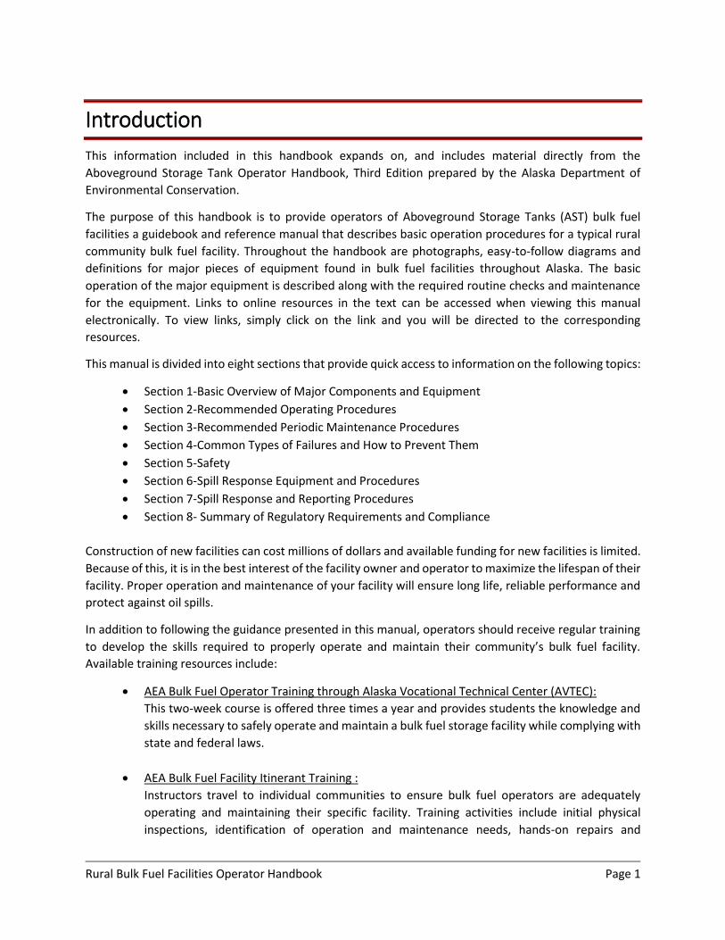
Introduction
This information included in this handbook expands on, and includes material directly from the
Aboveground Storage Tank Operator Handbook, Third Edition prepared by the Alaska Department of
Environmental Conservation.
The purpose of this handbook is to provide operators of Aboveground Storage Tanks (AST) bulk fuel
facilities a guidebook and reference manual that describes basic operation procedures for a typical rural
community bulk fuel facility. Throughout the handbook are photographs, easy-to-follow diagrams and
definitions for major pieces of equipment found in bulk fuel facilities throughout Alaska. The basic
operation of the major equipment is described along with the required routine checks and maintenance
for the equipment. Links to online resources in the text can be accessed when viewing this manual
electronically. To view links, simply click on the link and you will be directed to the corresponding
resources.
This manual is divided into eight sections that provide quick access to information on the following topics:
Section 1-Basic Overview of Major Components and Equipment
Section 2-Recommended Operating Procedures
Section 3-Recommended Periodic Maintenance Procedures
Section 4-Common Types of Failures and How to Prevent Them
Section 5-Safety
Section 6-Spill Response Equipment and Procedures
Section 7-Spill Response and Reporting Procedures
Section 8- Summary of Regulatory Requirements and Compliance
Construction of new facilities can cost millions of dollars and available funding for new facilities is limited.
Because of this, it is in the best interest of the facility owner and operator to maximize the lifespan of their
facility. Proper operation and maintenance of your facility will ensure long life, reliable performance and
protect against oil spills.
In addition to following the guidance presented in this manual, operators should receive regular training
to develop the skills required to properly operate and maintain their community’s bulk fuel facility.
Available training resources include:
AEA Bulk Fuel Operator Training through Alaska Vocational Technical Center (AVTEC):
This two-week course is offered three times a year and provides students the knowledge and
skills necessary to safely operate and maintain a bulk fuel storage facility while complying with
state and federal laws.
AEA Bulk Fuel Facility Itinerant Training :
Instructors travel to individual communities to ensure bulk fuel operators are adequately
operating and maintaining their specific facility. Training activities include initial physical
inspections, identification of operation and maintenance needs, hands-on repairs and
Rural Bulk Fuel Facilities Operator Handbook Page 2
replacement of minor maintenance needs and additional on-site training of specific facility
concerns and considerations.
For more information regarding these programs visit:
http://www.akenergyauthority.org/Programs/Training
Or contact:
Karin St. Clair, Project Control Specialist with AEA
Email. [email protected]
Tel. (907)-771-3081
Fax. (907) 771-3044
Rural Bulk Fuel Facilities Operator Handbook Page 3
TABLE OF CONTENTS
Introduction ................................................................................................................................................... 1
TABLE OF CONTENTS ..................................................................................................................................... 3
1 Aboveground Storage Tank Farm Facilities Components and Equipment ......................................... 4
2 Facility Operation ............................................................................................................................... 25
2.1 Operating Procedures ................................................................................................................ 25
2.2 Inventory Control ....................................................................................................................... 29
2.3 Preserving Fuel Quality .............................................................................................................. 36
3 Periodic Maintenance Procedures ..................................................................................................... 37
3.1 Inspections .................................................................................................................................. 37
3.2 Required Testing ......................................................................................................................... 44
3.3 Common Part Replacements ..................................................................................................... 45
3.4 Water Management ................................................................................................................... 45
3.5 Recordkeeping ............................................................................................................................ 47
4 Common Tank/Facility Failures ......................................................................................................... 48
5 Safety .................................................................................................................................................. 51
5.1 Fire and Explosion Safety/Prevention ....................................................................................... 51
5.2 Facility Safety.............................................................................................................................. 52
5.3 Personal Safety ........................................................................................................................... 53
6 Spill Preparedness .............................................................................................................................. 55
6.1 Facility Analysis and Inspection ................................................................................................. 55
6.2 Spill Response Equipment and Materials .................................................................................. 55
6.3 Operator Preparedness Training ............................................................................................... 56
6.4 Spill Response Plans ................................................................................................................... 56
6.5 Community Spill Response Program.......................................................................................... 57
7 Spill Response and Reporting ............................................................................................................ 58
7.1 Detecting Oil Spills...................................................................................................................... 58
7.2 Spill Response ............................................................................................................................. 58
8 Regulatory Requirements and Compliance ....................................................................................... 63

Rural Bulk Fuel Facilities Operator Handbook Page 4
1 Aboveground Storage Tank Farm Facilities Components
and Equipment
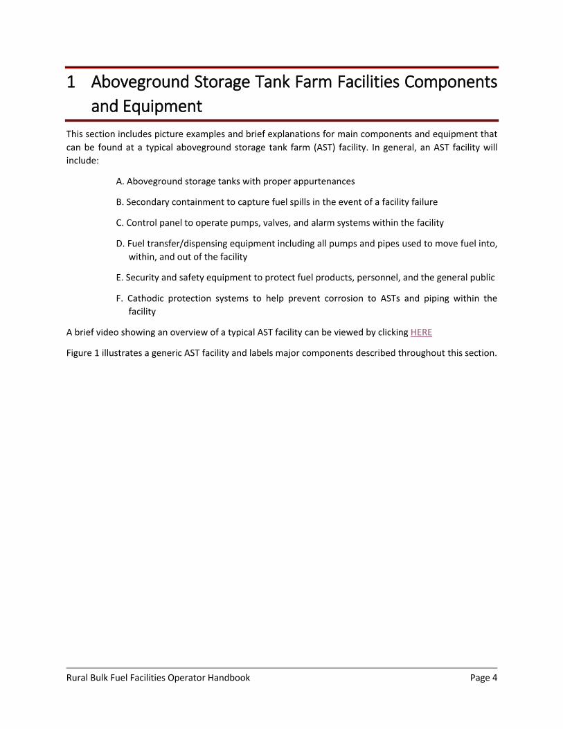
This section includes picture examples and brief explanations for main components and equipment that
can be found at a typical aboveground storage tank farm (AST) facility. In general, an AST facility will
include:
A. Aboveground storage tanks with proper appurtenances
B. Secondary containment to capture fuel spills in the event of a facility failure
C. Control panel to operate pumps, valves, and alarm systems within the facility
D. Fuel transfer/dispensing equipment including all pumps and pipes used to move fuel into,
within, and out of the facility
E. Security and safety equipment to protect fuel products, personnel, and the general public
F. Cathodic protection systems to help prevent corrosion to ASTs and piping within the
facility
A brief video showing an overview of a typical AST facility can be viewed by clicking HERE
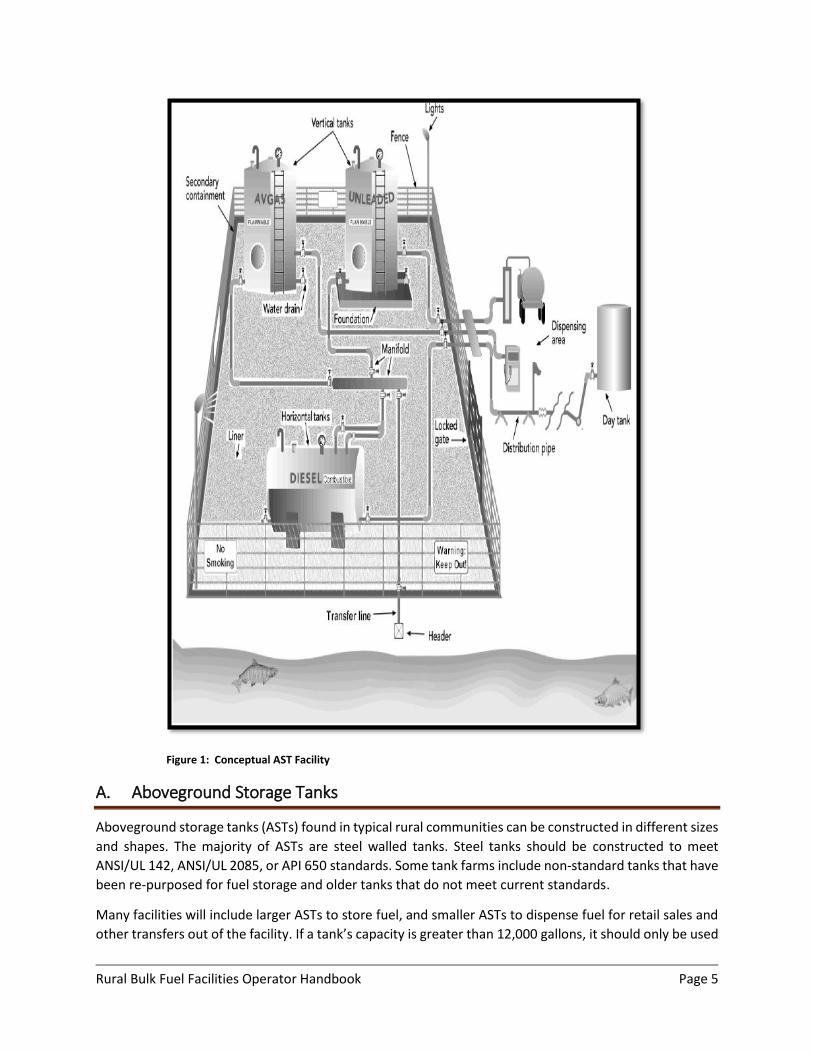
Figure 1 illustrates a generic AST facility and labels major components described throughout this section.
Rural Bulk Fuel Facilities Operator Handbook Page 5
Figure 1: Conceptual AST Facility
A. Aboveground Storage Tanks
Aboveground storage tanks (ASTs) found in typical rural communities can be constructed in different sizes
and shapes. The majority of ASTs are steel walled tanks. Steel tanks should be constructed to meet
ANSI/UL 142, ANSI/UL 2085, or API 650 standards. Some tank farms include non-standard tanks that have
been re-purposed for fuel storage and older tanks that do not meet current standards.
Many facilities will include larger ASTs to store fuel, and smaller ASTs to dispense fuel for retail sales and
other transfers out of the facility. If a tank’s capacity is greater than 12,000 gallons, it should only be used
Rural Bulk Fuel Facilities Operator Handbook Page 6
as a storage tank. If a tank’s capacity is less than 12,000 gallons, it can be used as a storage tank and/or a
dispensing tank for retail sales.
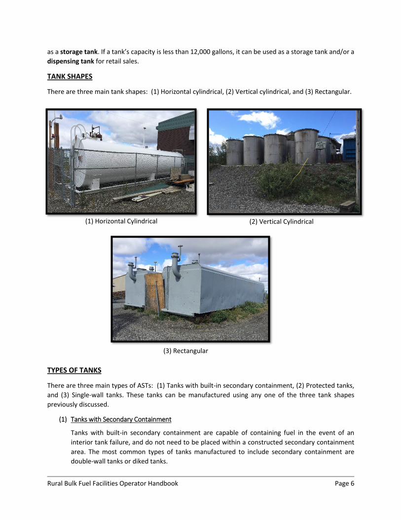
TANK SHAPES
There are three main tank shapes: (1) Horizontal cylindrical, (2) Vertical cylindrical, and (3) Rectangular.
TYPES OF TANKS
There are three main types of ASTs: (1) Tanks with built-in secondary containment, (2) Protected tanks,
and (3) Single-wall tanks. These tanks can be manufactured using any one of the three tank shapes
previously discussed.
(1) Tanks with Secondary Containment
Tanks with built-in secondary containment are capable of containing fuel in the event of an
interior tank failure, and do not need to be placed within a constructed secondary containment
area. The most common types of tanks manufactured to include secondary containment are
double-wall tanks or diked tanks.
(1) Horizontal Cylindrical
(2) Vertical Cylindrical
(3) Rectangular
Rural Bulk Fuel Facilities Operator Handbook Page 7
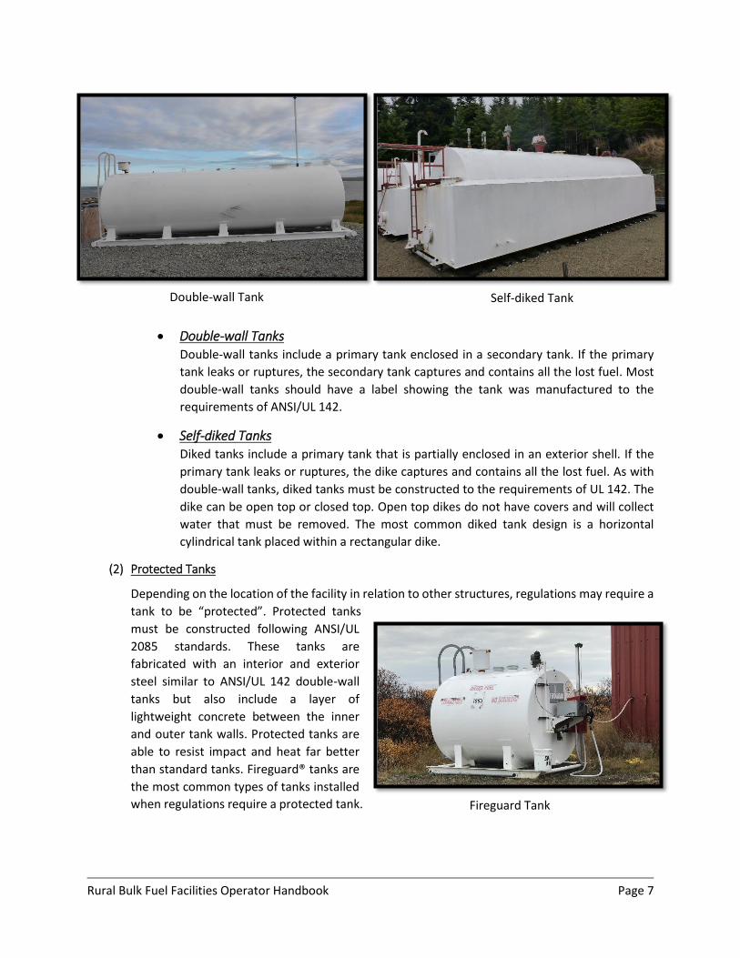
Double-wall Tanks Double-wall tanks include a primary tank enclosed in a secondary tank. If the primary
tank leaks or ruptures, the secondary tank captures and contains all the lost fuel. Most
double-wall tanks should have a label showing the tank was manufactured to the
requirements of ANSI/UL 142.
Self-diked Tanks Diked tanks include a primary tank that is partially enclosed in an exterior shell. If the
primary tank leaks or ruptures, the dike captures and contains all the lost fuel. As with
double-wall tanks, diked tanks must be constructed to the requirements of UL 142. The
dike can be open top or closed top. Open top dikes do not have covers and will collect
water that must be removed. The most common diked tank design is a horizontal
cylindrical tank placed within a rectangular dike.
(2) Protected Tanks
Depending on the location of the facility in relation to other structures, regulations may require a
tank to be “protected”. Protected tanks
must be constructed following ANSI/UL
2085 standards. These tanks are
fabricated with an interior and exterior
steel similar to ANSI/UL 142 double-wall
tanks but also include a layer of
lightweight concrete between the inner
and outer tank walls. Protected tanks are
able to resist impact and heat far better
than standard tanks. Fireguard® tanks are
the most common types of tanks installed
when regulations require a protected tank.
Double-wall Tank
Self-diked Tank
Fireguard Tank
Rural Bulk Fuel Facilities Operator Handbook Page 8
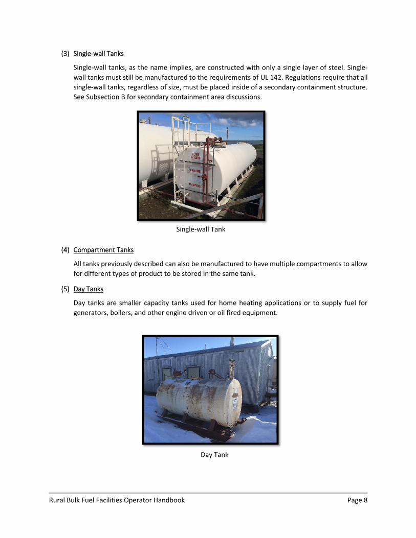
(3) Single-wall Tanks
Single-wall tanks, as the name implies, are constructed with only a single layer of steel. Single-
wall tanks must still be manufactured to the requirements of UL 142. Regulations require that all
single-wall tanks, regardless of size, must be placed inside of a secondary containment structure.
See Subsection B for secondary containment area discussions.
(4) Compartment Tanks
All tanks previously described can also be manufactured to have multiple compartments to allow
for different types of product to be stored in the same tank.
(5) Day Tanks
Day tanks are smaller capacity tanks used for home heating applications or to supply fuel for
generators, boilers, and other engine driven or oil fired equipment.
Single-wall Tank
Day Tank
Rural Bulk Fuel Facilities Operator Handbook Page 9
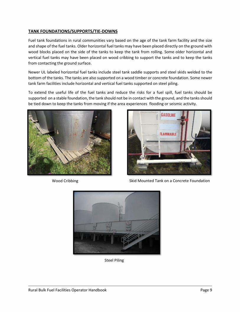
TANK FOUNDATIONS/SUPPORTS/TIE-DOWNS
Fuel tank foundations in rural communities vary based on the age of the tank farm facility and the size
and shape of the fuel tanks. Older horizontal fuel tanks may have been placed directly on the ground with
wood blocks placed on the side of the tanks to keep the tank from rolling. Some older horizontal and
vertical fuel tanks may have been placed on wood cribbing to support the tanks and to keep the tanks
from contacting the ground surface.
Newer UL labeled horizontal fuel tanks include steel tank saddle supports and steel skids welded to the
bottom of the tanks. The tanks are also supported on a wood timber or concrete foundation. Some newer
tank farm facilities include horizontal and vertical fuel tanks supported on steel piling.
To extend the useful life of the fuel tanks and reduce the risks for a fuel spill, fuel tanks should be
supported on a stable foundation, the tank should not be in contact with the ground, and the tanks should
be tied down to keep the tanks from moving if the area experiences flooding or seismic activity.
Skid Mounted Tank on a Concrete Foundation Wood Cribbing
Steel Piling
Rural Bulk Fuel Facilities Operator Handbook Page 10
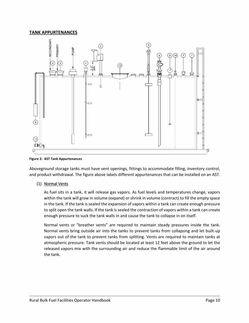
TANK APPURTENANCES
Figure 2: AST Tank Appurtenances
Aboveground storage tanks must have vent openings, fittings to accommodate filling, inventory control,
and product withdrawal. The figure above labels different appurtenances that can be installed on an AST.
(1) Normal Vents
As fuel sits in a tank, it will release gas vapors. As fuel levels and temperatures change, vapors
within the tank will grow in volume (expand) or shrink in volume (contract) to fill the empty space
in the tank. If the tank is sealed the expansion of vapors within a tank can create enough pressure
to split open the tank walls. If the tank is sealed the contraction of vapors within a tank can create
enough pressure to suck the tank walls in and cause the tank to collapse in on itself.
Normal vents or “breather vents” are required to maintain steady pressures inside the tank.
Normal vents bring outside air into the tanks to prevent tanks from collapsing and let built-up
vapors out of the tank to prevent tanks from splitting. Vents are required to maintain tanks at
atmospheric pressure. Tank vents should be located at least 12 feet above the ground to let the
released vapors mix with the surrounding air and reduce the flammable limit of the air around
the tank.
Rural Bulk Fuel Facilities Operator Handbook Page 11
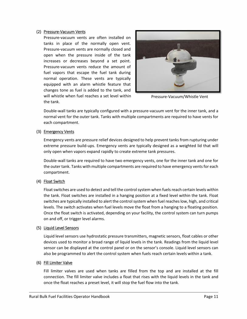
(2) Pressure-Vacuum Vents
Pressure-vacuum vents are often installed on
tanks in place of the normally open vent.
Pressure-vacuum vents are normally closed and
open when the pressure inside of the tank
increases or decreases beyond a set point.
Pressure-vacuum vents reduce the amount of
fuel vapors that escape the fuel tank during
normal operation. These vents are typically
equipped with an alarm whistle feature that
changes tone as fuel is added to the tank, and
will whistle when fuel reaches a set level within
the tank.
Double-wall tanks are typically configured with a pressure-vacuum vent for the inner tank, and a
normal vent for the outer tank. Tanks with multiple compartments are required to have vents for
each compartment.
(3) Emergency Vents
Emergency vents are pressure relief devices designed to help prevent tanks from rupturing under
extreme pressure build-ups. Emergency vents are typically designed as a weighted lid that will
only open when vapors expand rapidly to create extreme tank pressures.
Double-wall tanks are required to have two emergency vents, one for the inner tank and one for
the outer tank. Tanks with multiple compartments are required to have emergency vents for each
compartment.
(4) Float Switch
Float switches are used to detect and tell the control system when fuels reach certain levels within
the tank. Float switches are installed in a hanging position at a fixed level within the tank. Float
switches are typically installed to alert the control system when fuel reaches low, high, and critical
levels. The switch activates when fuel levels move the float from a hanging to a floating position.
Once the float switch is activated, depending on your facility, the control system can turn pumps
on and off, or trigger level alarms.
(5) Liquid Level Sensors
Liquid level sensors use hydrostatic pressure transmitters, magnetic sensors, float cables or other
devices used to monitor a broad range of liquid levels in the tank. Readings from the liquid level
sensor can be displayed at the control panel or on the sensor’s console. Liquid level sensors can
also be programmed to alert the control system when fuels reach certain levels within a tank.
(6) Fill Limiter Valve
Fill limiter valves are used when tanks are filled from the top and are installed at the fill
connection. The fill limiter valve includes a float that rises with the liquid levels in the tank and
once the float reaches a preset level, it will stop the fuel flow into the tank.
Pressure-Vacuum/Whistle Vent
Rural Bulk Fuel Facilities Operator Handbook Page 12
(7) Gauge Hatch
A gauge hatch is installed at the top of the fuel tank and provides access for gauging or collecting
product samples. The gauge hatch typically includes a locking lid for tank security.
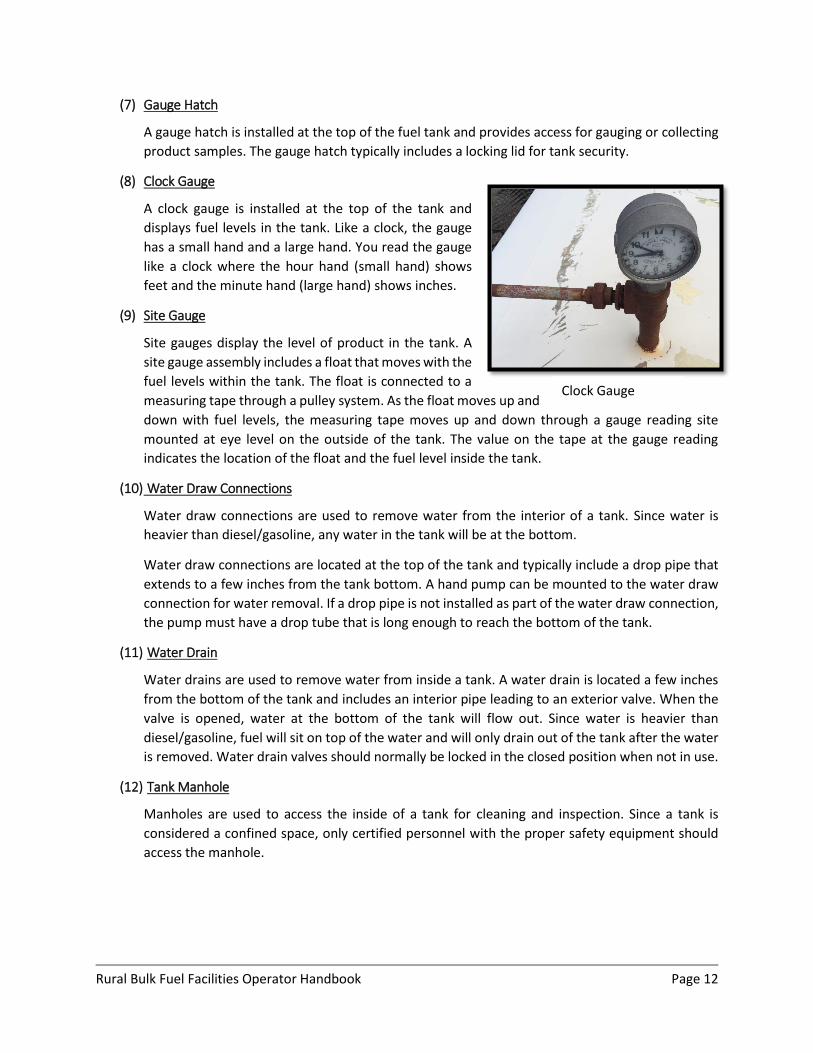
(8) Clock Gauge
A clock gauge is installed at the top of the tank and
displays fuel levels in the tank. Like a clock, the gauge
has a small hand and a large hand. You read the gauge
like a clock where the hour hand (small hand) shows
feet and the minute hand (large hand) shows inches.
(9) Site Gauge
Site gauges display the level of product in the tank. A
site gauge assembly includes a float that moves with the
fuel levels within the tank. The float is connected to a
measuring tape through a pulley system. As the float moves up and
down with fuel levels, the measuring tape moves up and down through a gauge reading site
mounted at eye level on the outside of the tank. The value on the tape at the gauge reading
indicates the location of the float and the fuel level inside the tank.
(10) Water Draw Connections
Water draw connections are used to remove water from the interior of a tank. Since water is
heavier than diesel/gasoline, any water in the tank will be at the bottom.
Water draw connections are located at the top of the tank and typically include a drop pipe that
extends to a few inches from the tank bottom. A hand pump can be mounted to the water draw
connection for water removal. If a drop pipe is not installed as part of the water draw connection,
the pump must have a drop tube that is long enough to reach the bottom of the tank.
(11) Water Drain
Water drains are used to remove water from inside a tank. A water drain is located a few inches
from the bottom of the tank and includes an interior pipe leading to an exterior valve. When the
valve is opened, water at the bottom of the tank will flow out. Since water is heavier than
diesel/gasoline, fuel will sit on top of the water and will only drain out of the tank after the water
is removed. Water drain valves should normally be locked in the closed position when not in use.
(12) Tank Manhole
Manholes are used to access the inside of a tank for cleaning and inspection. Since a tank is
considered a confined space, only certified personnel with the proper safety equipment should
access the manhole.
Clock Gauge
Rural Bulk Fuel Facilities Operator Handbook Page 13
B. Secondary Containment
The purpose of secondary containment is to prevent petroleum products from flowing onto the lands or
into waters in the event of a spill. Secondary containment is required for all tanks and areas of fuel
transfers including truck fill stations and header connections.
Secondary containment areas must be sized to capture the entire contents of the largest tank within the
area. If the secondary containment is open to rainfall or snowfall, it must be designed to also hold volumes
from a 25-year, 24-hour storm event. (IFC 2015, 5004.2.2.4). The containment area must also include a
way to drain snowmelt and rain water out of the containment area.
Secondary containment can be provided within the tank itself (double-wall tanks and self-diked tanks) or
tanks can be placed inside a constructed secondary containment area. The entire constructed secondary
containment area is lined with a material that will not allow petroleum products to seep into the ground.
The liner is typically covered with a layer of sand and gravel and the area is contained with vertical or
sloped walls. Depending on space availability, walls can be constructed vertically using concrete or wood,
or sloped earthen berms.
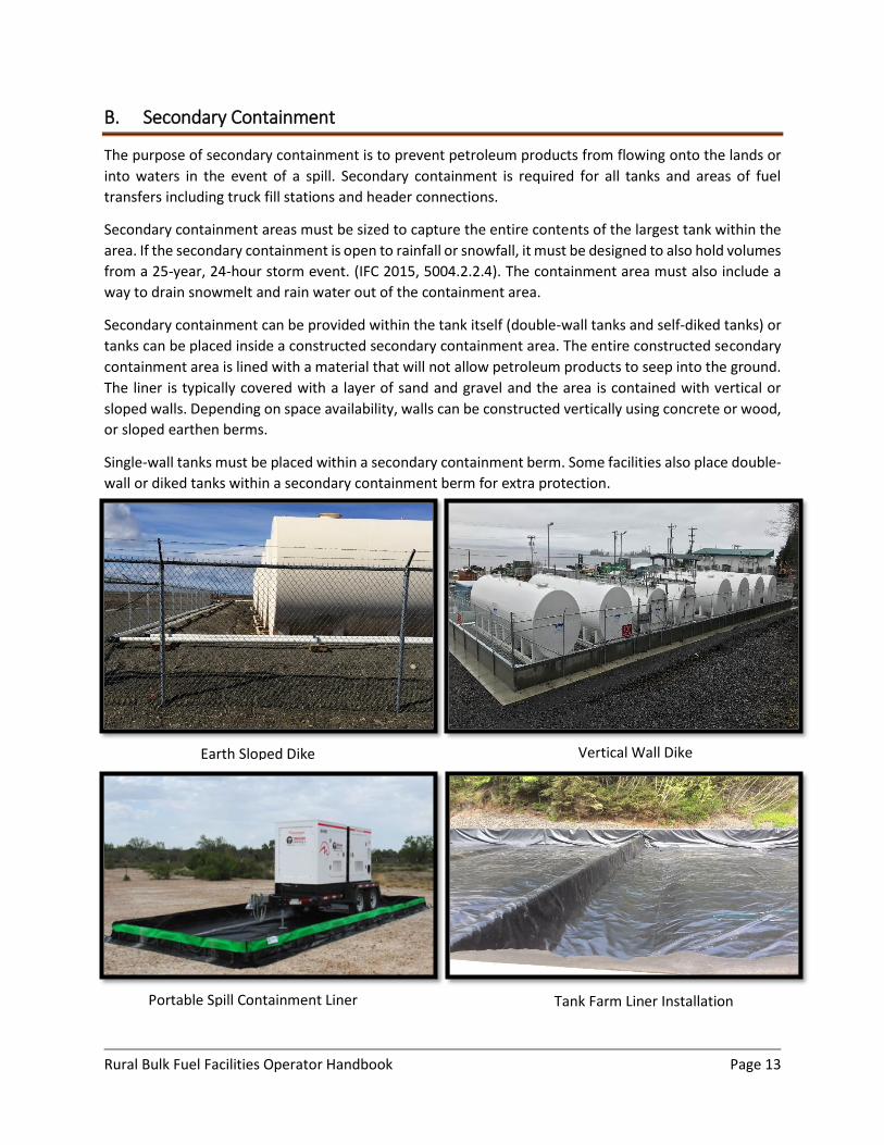
Single-wall tanks must be placed within a secondary containment berm. Some facilities also place double-
wall or diked tanks within a secondary containment berm for extra protection.
Earth Sloped Dike
Vertical Wall Dike
Tank Farm Liner Installation
Portable Spill Containment Liner
Rural Bulk Fuel Facilities Operator Handbook Page 14
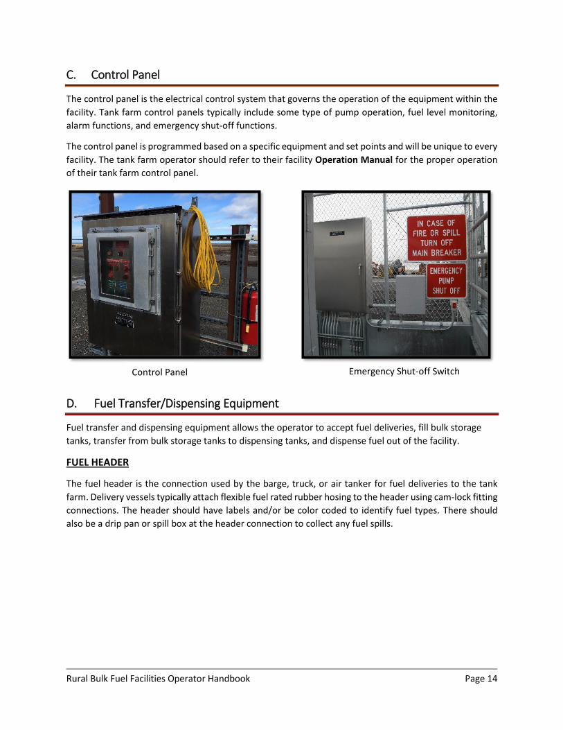
C. Control Panel
The control panel is the electrical control system that governs the operation of the equipment within the
facility. Tank farm control panels typically include some type of pump operation, fuel level monitoring,
alarm functions, and emergency shut-off functions.
The control panel is programmed based on a specific equipment and set points and will be unique to every
facility. The tank farm operator should refer to their facility Operation Manual for the proper operation
of their tank farm control panel.
D. Fuel Transfer/Dispensing Equipment
Fuel transfer and dispensing equipment allows the operator to accept fuel deliveries, fill bulk storage
tanks, transfer from bulk storage tanks to dispensing tanks, and dispense fuel out of the facility.
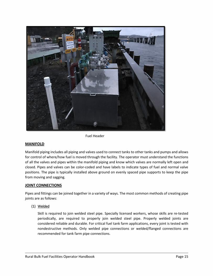
FUEL HEADER
The fuel header is the connection used by the barge, truck, or air tanker for fuel deliveries to the tank
farm. Delivery vessels typically attach flexible fuel rated rubber hosing to the header using cam-lock fitting
connections. The header should have labels and/or be color coded to identify fuel types. There should
also be a drip pan or spill box at the header connection to collect any fuel spills.
Control Panel
Emergency Shut-off Switch
Rural Bulk Fuel Facilities Operator Handbook Page 15
MANIFOLD
Manifold piping includes all piping and valves used to connect tanks to other tanks and pumps and allows
for control of where/how fuel is moved through the facility. The operator must understand the functions
of all the valves and pipes within the manifold piping and know which valves are normally left open and
closed. Pipes and valves can be color-coded and have labels to indicate types of fuel and normal valve
positions. The pipe is typically installed above ground on evenly spaced pipe supports to keep the pipe
from moving and sagging.
JOINT CONNECTIONS
Pipes and fittings can be joined together in a variety of ways. The most common methods of creating pipe
joints are as follows:
(1) Welded
Skill is required to join welded steel pipe. Specially licensed workers, whose skills are re-tested
periodically, are required to properly join welded steel pipe. Properly welded joints are
considered reliable and durable. For critical fuel tank farm applications, every joint is tested with
nondestructive methods. Only welded pipe connections or welded/flanged connections are
recommended for tank farm pipe connections.
Fuel Header
Rural Bulk Fuel Facilities Operator Handbook Page 16
(2) Threaded
Threaded joints include an end with threads that screw into an end with grooves. When ends are
screwed together there are small gaps between the threads and grooves. To make joints leak free,
the threaded end should be wrapped in a pipe seal tape, or a sealant compound should be applied.
Threaded joints and fittings are mainly used with smaller pipes with diameters 2-inches or less.
Many older tank farm facilities were constructed with threaded pipe connections. Threaded pipe
connections typically are not as strong or as reliable as welded pipe joints. Over time, threaded
pipe joints may develop leaks and require maintenance.
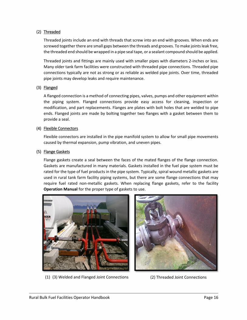
(3) Flanged
A flanged connection is a method of connecting pipes, valves, pumps and other equipment within
the piping system. Flanged connections provide easy access for cleaning, inspection or
modification, and part replacements. Flanges are plates with bolt holes that are welded to pipe
ends. Flanged joints are made by bolting together two flanges with a gasket between them to
provide a seal.
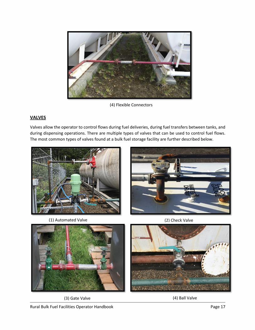
(4) Flexible Connectors
Flexible connectors are installed in the pipe manifold system to allow for small pipe movements
caused by thermal expansion, pump vibration, and uneven pipes.
(5) Flange Gaskets
Flange gaskets create a seal between the faces of the mated flanges of the flange connection.
Gaskets are manufactured in many materials. Gaskets installed in the fuel pipe system must be
rated for the type of fuel products in the pipe system. Typically, spiral wound metallic gaskets are
used in rural tank farm facility piping systems, but there are some flange connections that may
require fuel rated non-metallic gaskets. When replacing flange gaskets, refer to the facility
Operation Manual for the proper type of gaskets to use.
(1) (3) Welded and Flanged Joint Connections
(2) Threaded Joint Connections
Rural Bulk Fuel Facilities Operator Handbook Page 17
VALVES
Valves allow the operator to control flows during fuel deliveries, during fuel transfers between tanks, and
during dispensing operations. There are multiple types of valves that can be used to control fuel flows.
The most common types of valves found at a bulk fuel storage facility are further described below.
(4) Flexible Connectors
(1) Automated Valve
(2) Check Valve
(3) Gate Valve
(4) Ball Valve
Rural Bulk Fuel Facilities Operator Handbook Page 18
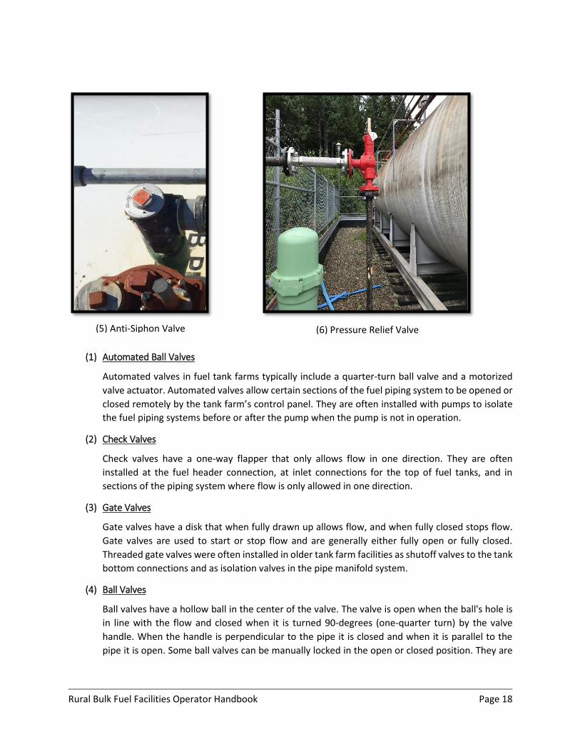
(1) Automated Ball Valves
Automated valves in fuel tank farms typically include a quarter-turn ball valve and a motorized
valve actuator. Automated valves allow certain sections of the fuel piping system to be opened or
closed remotely by the tank farm’s control panel. They are often installed with pumps to isolate
the fuel piping systems before or after the pump when the pump is not in operation.
(2) Check Valves
Check valves have a one-way flapper that only allows flow in one direction. They are often
installed at the fuel header connection, at inlet connections for the top of fuel tanks, and in
sections of the piping system where flow is only allowed in one direction.
(3) Gate Valves
Gate valves have a disk that when fully drawn up allows flow, and when fully closed stops flow.
Gate valves are used to start or stop flow and are generally either fully open or fully closed.
Threaded gate valves were often installed in older tank farm facilities as shutoff valves to the tank
bottom connections and as isolation valves in the pipe manifold system.
(4) Ball Valves
Ball valves have a hollow ball in the center of the valve. The valve is open when the ball's hole is
in line with the flow and closed when it is turned 90-degrees (one-quarter turn) by the valve
handle. When the handle is perpendicular to the pipe it is closed and when it is parallel to the
pipe it is open. Some ball valves can be manually locked in the open or closed position. They are
(5) Anti-Siphon Valve
(6) Pressure Relief Valve
Rural Bulk Fuel Facilities Operator Handbook Page 19
often installed as shutoff valves to the tank bottom connections and as isolation valves in the pipe
manifold system.
(5) Anti-Siphon Valves
Anti-siphon valves are installed at the connections on the top of fuel tanks and are used to prevent
accidental siphoning of fuel tanks should a leak or break occur in the fuel supply line. Anti-siphon
valves are normally closed and will only open if fuel is being pumped out of the tank and if the
suction side of the pump overcomes the anti-siphon valve spring.
(6) Pressure Relief Valves
Pressure relief valves are a type of safety valve used to limit the pressure within the fuel piping
system when fuels expand due to temperature changes. They are typically installed at each
isolation valve in the fuel piping system. If an isolation valve closes part of the fuel piping system,
a pressure relief valve connected to the closed pipe section will allow excess pressure in the closed
pipe to bypass the isolation valve.
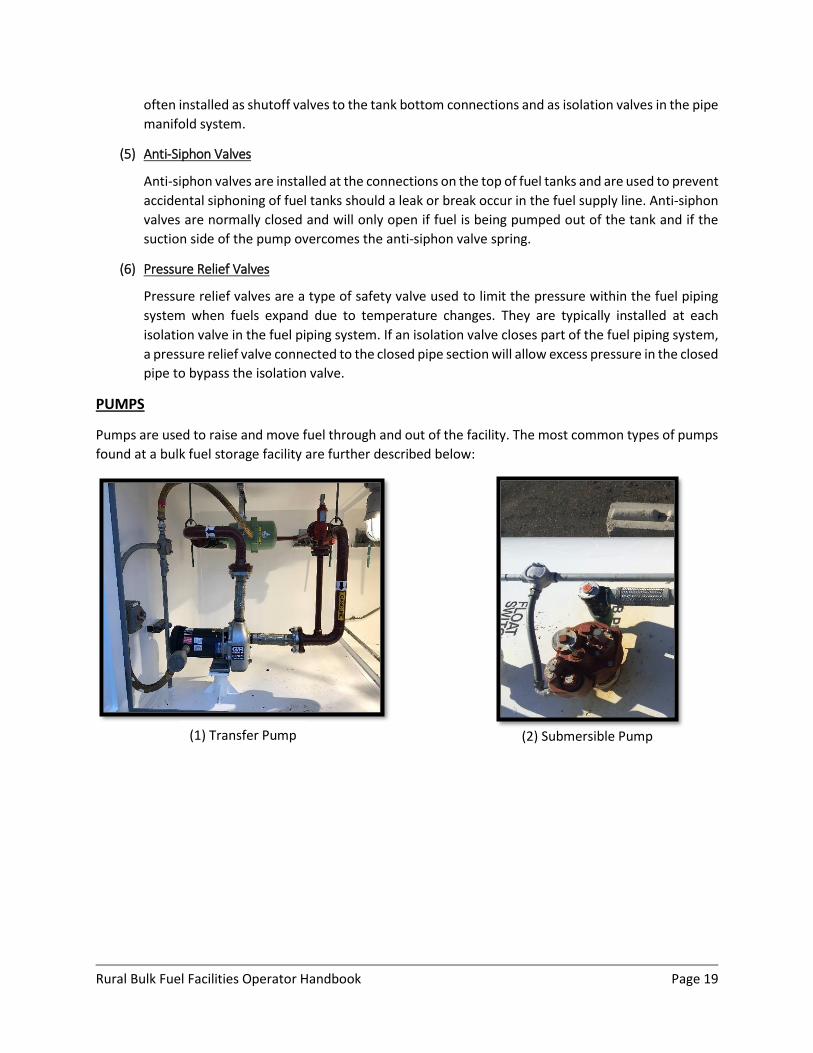
PUMPS
Pumps are used to raise and move fuel through and out of the facility. The most common types of pumps
found at a bulk fuel storage facility are further described below:
(1) Transfer Pump
(2) Submersible Pump
Rural Bulk Fuel Facilities Operator Handbook Page 20
(1) Transfer Pumps
Transfer pumps create pressure to transfer product from bulk storage tanks to smaller dispensing
tanks within in the tank farm.
(2) Submersible Pumps
Submersible pumps are installed inside of the tank farm dispensing tanks and are used to transfer
fuel to dispensers outside the secondary containment area. A submersible pump assembly
includes a long cylindrical pump and motor that is completely submerged in the fuel inside the
tank. When the pump is turned on, it pumps fuel up through one of the connections at the top of
the tank.
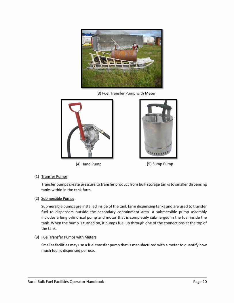
(3) Fuel Transfer Pumps with Meters
Smaller facilities may use a fuel transfer pump that is manufactured with a meter to quantify how
much fuel is dispensed per use.
(3) Fuel Transfer Pump with Meter
(4) Hand Pump
(5) Sump Pump
Rural Bulk Fuel Facilities Operator Handbook Page 21
(4) Hand Pumps
Hand pumps are typically used to remove water from the bottoms of tanks. They are manually
operated by lifting up and pushing down a lever to create suction.
(5) Sump Pump
Sump pumps are used to remove storm water from secondary containment dikes.
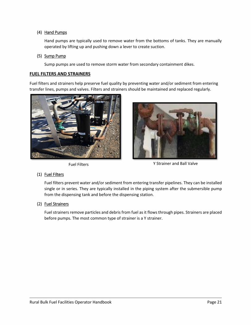
FUEL FILTERS AND STRAINERS
Fuel filters and strainers help preserve fuel quality by preventing water and/or sediment from entering
transfer lines, pumps and valves. Filters and strainers should be maintained and replaced regularly.
(1) Fuel Filters
Fuel filters prevent water and/or sediment from entering transfer pipelines. They can be installed
single or in series. They are typically installed in the piping system after the submersible pump
from the dispensing tank and before the dispensing station.
(2) Fuel Strainers
Fuel strainers remove particles and debris from fuel as it flows through pipes. Strainers are placed
before pumps. The most common type of strainer is a Y strainer.
Fuel Filters Y Strainer and Ball Valve
Rural Bulk Fuel Facilities Operator Handbook Page 22
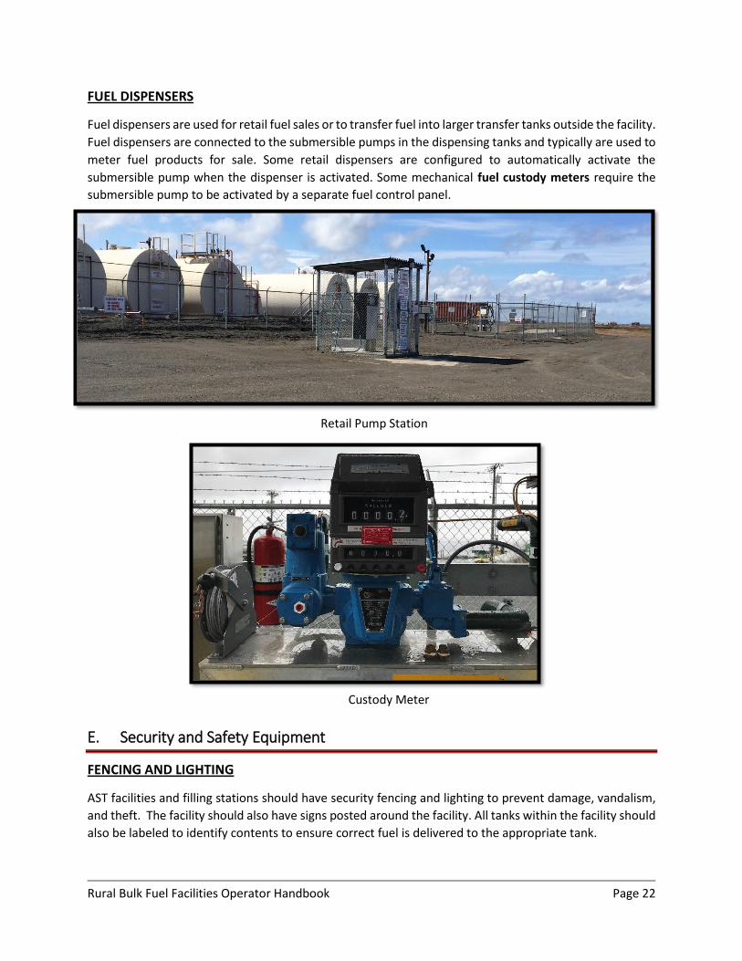
FUEL DISPENSERS
Fuel dispensers are used for retail fuel sales or to transfer fuel into larger transfer tanks outside the facility.
Fuel dispensers are connected to the submersible pumps in the dispensing tanks and typically are used to
meter fuel products for sale. Some retail dispensers are configured to automatically activate the
submersible pump when the dispenser is activated. Some mechanical fuel custody meters require the
submersible pump to be activated by a separate fuel control panel.
E. Security and Safety Equipment
FENCING AND LIGHTING
AST facilities and filling stations should have security fencing and lighting to prevent damage, vandalism,
and theft. The facility should also have signs posted around the facility. All tanks within the facility should
also be labeled to identify contents to ensure correct fuel is delivered to the appropriate tank.
Retail Pump Station
Custody Meter
Rural Bulk Fuel Facilities Operator Handbook Page 23
FACILITY SIGNS
Signs should be posted around the facility so they can be seen from every side of the tank farm. In general,
caution signs such as “NO SMOKING” and “NO OPEN FLAMES” should have red text. Instructional signs
such as “AUTHORIZED PERSONNEL ONLY” should have black text.
All tanks within the facility should also be labeled to identify contents to ensure correct fuel is delivered
to the appropriate tank. A warning sign stating “DANGER-FLAMMABLE LIQUIDS” should also be posted on
the tank shell.
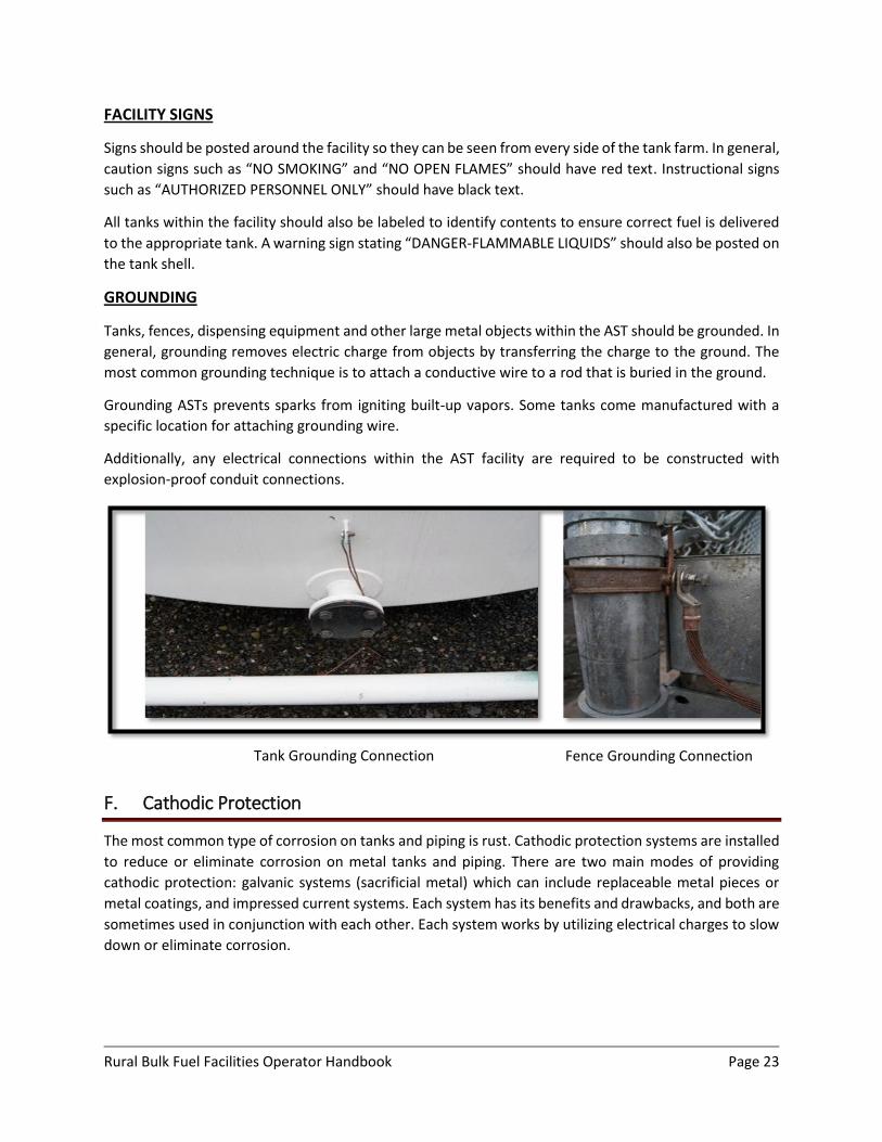
GROUNDING
Tanks, fences, dispensing equipment and other large metal objects within the AST should be grounded. In
general, grounding removes electric charge from objects by transferring the charge to the ground. The
most common grounding technique is to attach a conductive wire to a rod that is buried in the ground.
Grounding ASTs prevents sparks from igniting built-up vapors. Some tanks come manufactured with a
specific location for attaching grounding wire.
Additionally, any electrical connections within the AST facility are required to be constructed with
explosion-proof conduit connections.
F. Cathodic Protection
The most common type of corrosion on tanks and piping is rust. Cathodic protection systems are installed
to reduce or eliminate corrosion on metal tanks and piping. There are two main modes of providing
cathodic protection: galvanic systems (sacrificial metal) which can include replaceable metal pieces or
metal coatings, and impressed current systems. Each system has its benefits and drawbacks, and both are
sometimes used in conjunction with each other. Each system works by utilizing electrical charges to slow
down or eliminate corrosion.
Tank Grounding Connection Fence Grounding Connection
Rural Bulk Fuel Facilities Operator Handbook Page 24
GALVANIC SYSTEMS
Cathodic protection provided by sacrificial metals can also be referred to as galvanic systems. In this
application, the sacrificial metal, or anode, is chosen because it will corrode more readily than the metal
that it is meant to protect. In order to work properly, the anode must be connected to the tank or pipe it
is protecting.
(1) Zinc Coatings (Galvanizing/Zinc Primers)
One common way of providing corrosion protection is through the use of a zinc rich primer, which
is installed prior to final painting. Zinc rich primers are most commonly used on larger items such
as ASTs and buried pipes.
One other common form of providing a zinc coating is galvanization. The galvanization process
deposits a thin layer of zinc onto the surface of a metal, which protects it from further corrosion.
Galvanization is typically used on items such as nails, bolts, hand rails, etc. Galvanized metals are
easy to spot because when new they will have a shiny gray color; weathered galvanization will
often have white splotches or a chalk-like coating.
(2) Sacrificial Metal Anodes
Many ASTs and pipes employ a form of galvanic corrosion protection, which use sacrificial metal
anodes. Anodes achieve corrosion protection the same way as coatings, however, these systems
use large pieces of metal, which are directly attached to the item that it is meant to protect.
Common ways of attaching sacrificial metal anodes for tanks are to bolt the anode directly to the
inside tank wall. For buried steel tanks and piping and for above ground steel tanks, anodes are
connected to steel to be protected via a cable and placed in the ground next to the pipe or tank.
IMPRESSED CURRENT SYSTEMS
On newer, large structures which require cathodic protection, impressed current systems are sometimes
used. These systems work by running a weak electrical charge through the structure which is then
transferred through the soil to a network of anodes buried around the structure. The electrical charge is
induced from a device called a rectifier, which is specially tuned to the protected structure and the overall
site conditions. One of the primary benefits of impressed current systems is their low maintenance
requirements after installation.

Rural Bulk Fuel Facilities Operator Handbook Page 25
2 Facility Operation
This section discusses basic operational practices for a bulk fuel facility. Major topics include:
General Operating Procedures - includes step by step procedures for day to day activities and fuel
transfers.
Inventory Control - includes step by step procedures for calculating and monitoring fuel volumes.
Best practices for preserving fuel quality.
2.1 Operating Procedures
The facility operator is typically responsible for (A) Daily System Startup/Shutdown; (B) Filling of
Dispensing Tanks; (C) Dispensing Procedures; and (D) Receiving Fuel Deliveries. The following sections
provide general step-by-step guidelines for each of these responsibilities, as well as troubleshooting
techniques to use if the system is not working properly. Appendix B includes checklists for each of these
general procedures. Note that depending on the size and function of your facility, some of the steps may
not apply.
For all procedures, tank isolation through proper valve control is extremely important.
A. Daily System Startup/Shutdown
Daily system startup and shutdown procedures can vary greatly depending on your facility’s layout and
control system.
FACILITY STARTUP
Visually inspect dispensing area, dispensing tanks, and storage tanks for any evidence of spills
leaks or damage.
Verify proper valves are closed and locked.
Turn on appropriate control panels.
Observe stormwater level within secondary containment and remove as required (see Section 3
for procedure).
Check fuel level in dispensing tanks. Follow Procedure C if dispensing tank(s) need to be filled.
FACILITY SHUTDOWN
Turn appropriate control panels off.
Verify all valves and switches are closed and locked.
Close and lock security gates.
Rural Bulk Fuel Facilities Operator Handbook Page 26
B. Dispensing Procedures
Facilities may include dispensing equipment for smaller retail sales and large transfers into fuel trucks.
GENERAL PROCEDURE
Unlock security gate.
Open appropriate fuel dispenser valve.
Turn on dispenser pump.
If required, set fuel meter to record amount of fuel to be dispensed.
Ensure meter is working.
Dispense desired quantity of fuel.
Turn off dispenser pump.
Close fuel dispenser valve.
Lock security gate.
TROUBLESHOOTING
If fuel does not flow out of the nozzle at the dispenser:
Check to ensure the appropriate control panels are on.
Check to see if any emergency pump shutoff switches have been tripped.
o If emergency pump shutoff switches have been tripped DO NOT simply reset or
deactivate them, diagnose the cause of the shutoff and make appropriate repairs.
Verify fuel level in the dispensing tank.
Verify proper valves are open.
If fuel is flowing slow:
Replace filter element inside the dispenser.
Check nozzle for frost. If nozzle is frozen, close valves to the dispenser. Remove nozzle, being
careful to catch all drips, and then place nozzle in a warm space to thaw and dry thoroughly.
Reinstall the nozzle and open the valves to the dispenser.
C. Dispensing Tank Filling Procedures
If your facility has storage tanks greater than 12,000 gallons, fuel must be transferred to a dispensing tank
before it can be distributed outside of the facility. Your facility should have a pre-determined “low level”
for the dispensing tank that lets you know when you should fill the tank.
GENERAL PROCEDURE
Check fuel level in the dispensing tank.
Select the bulk tank from which you will be transferring from and verify fuel level.
Unlock and open valves between the selected bulk tank and dispensing tank. Make sure all other
bulk tank valves and manifold valves are CLOSED AND LOCKED.
Rural Bulk Fuel Facilities Operator Handbook Page 27
Discontinue all vehicle-dispensing operations while transferring fuel to the dispensing tank.
Use the control panel to start fuel transfer. If you do not have a control panel with this function,
manually start the transfer pump.
Continuously monitor storage tank and dispensing tank fuel levels during transfer.
When the dispensing tank reaches 90% full, stop fuel transfer.
Once fuel transfer operations are complete, turn and lock valves in the closed position, and ensure
transfer pump switch is in the off position.
TROUBLESHOOTING
If pump is not turning on:
Check the control panel and verify pump switch is on and pump “ON” light is illuminated. If pump switch is on and light is not illuminated, check the pump circuit breaker.
Check to see if emergency pump shutoffs have been activated.
Ensure dispensing tank is not in use. Many facilities have lockout features that prevent filling the dispensing tank if dispensing operations are occurring.
If transfer pump is running but no fuel is flowing:
Verify proper valves are open.
If your system includes actuating (motorized) valves, check to see if they are turning open. If the motorized valve is stuck, it can be manually opened and closed in an emergency situation using a wrench. If the motorized valve is not working properly it should be serviced by a qualified technician or replaced.
Verify the fuel level in the storage tank.
D. Offloading Procedures
Offloading procedures can vary depending on how fuel is delivered to your facility. Barge deliveries must
comply with United States Coast Guard (USCG) regulations, which require that inspections be performed
prior to delivery with backup documentation showing:
Declaration of Inspection (DOI);
Pre-transfer meeting with barge personnel;
Results from hydrostatic pressure test completed before the first delivery of the season.
The following procedure summarizes the USCG regulations for barge deliveries. The tank farm operator
must understand and follow the requirements in their tank farm’s USCG Operations Manual, Prevention
Control and Countermeasure Plan (SPCC), as required by the EPA and the Facility Response Plan (FRP) as
required by the Coast Guard and EPA, during each fuel transfer operation.
If your facility receives fuel from a cargo plane, or truck, the same procedure can be followed as a general
best practice.
Rural Bulk Fuel Facilities Operator Handbook Page 28
BEFORE BEGINNING A TRANSFER
Check the fuel level of the receiving tank to determine how much product it can take. It is important to determine a Safe Gauge Height (SGH), that is, how much fuel the tank can safely hold allowing for expansion due to temperature variations. A rule of thumb is the SGH should not be over 90% in the summer and not over 95% in the winter. In order to determine the SGH one must know the tank’s storage capacity and how to properly gauge the tank. These topics are discussed in the inventory control section.
Develop a product receiving plan for each tank that lists the volume to be delivered to each tank in sequential order.
Walk the pipeline or hose to check for visible leaks, cracks, or damage to the pipe or hose. Put drip pans under hose connections and confirm all drain plugs are in place.
Confirm fire extinguishers are in place.
Ensure all stormwater is removed from the containment dike and from the spill box at the header connection.
Verify all valves along the pipeline between the tanks and header are CLOSED.
Have a pre-transfer meeting with the barge operators and facility operators. The USCG requires this meeting and for the parties to go over and sign a Declaration of Inspection (DOI). Procedures that will be used during the transfer are included in the DOI. A sample DOI form is included in Appendix B.
Determine how much fuel is above the receiving pipe inside the tank. If there is less than a foot of fuel above the receiving pipe, transfer fuel at a reduced rate until at least one foot of fuel is covering the pipe. This will reduce the potential for explosions caused by static electricity that may be generated when fuel is pumped into the tank at a high rate.
Ensure all required personnel are available and prepared.
DURING THE TRANSFER
Remove cap at the header and allow fuel barge personnel to connect their fuel transfer hose. Open the valve at the marine header.
Upon command from fuel barge personnel, open valves between the marine header and the first storage tank designated to be filled in the receiving plan.
Begin the transfer at a reduced rate until you are sure the product is going into the correct tank and that there are no major problems or leaks.
DO NOT WALK AWAY DURING A TRANSFER. Make sure an operator is at the site during the entire transfer. Several spills have occurred at AST facilities because the operator did not follow this rule. Since transfers occur at various rates depending on equipment, operators must be patient.
Maintain communication between the barge operators and the facility operators at all times. Use intrinsically safe hand-held radios for communications.
Rural Bulk Fuel Facilities Operator Handbook Page 29
Check tank level at regular intervals. As the tank fills, frequency of checks on the tank level should be increased to avoid overfilling the tank.
Reduce the transfer rates when nearing the SGH to avoid overfilling the tank. Note: if the whistle vent begins to alarm while filling a tank, check the tank level immediately and be prepared to slow down or stop pumping as required.
Notify the fuel barge personnel when the transfer procedure is almost complete. This will ensure that fuel barge pumps can be shut down before valves within the AST facility are closed. If tank valves are closed first, high pressure in the lines may cause a “hydraulic hammer” to occur which can cause fuel spillage or significant damage to valves and/or piping.
Close and lock tank valves.
Repeat for each tank in the order specified in the receiving plan.
WHEN THE TRANSFER IS COMPLETE
Close all valves between the marine header and manifold.
After fuel barge personnel remove hoses, replace cap over marine header and lock.
Conduct a post-transfer meeting between the fuel barge personnel and the facility operators. Ensure that all required personnel sign-off on the DOI.
Allow a minimum of a 30-minute relaxation period for static electricity to dissipate before gauging tanks or beginning transfer operations.
Allow product to settle for a minimum of two days prior to dipping with water cut paste (refer to Inventory control for tank dipping procedures). Waiting to dip the tanks will allow water to settle to the bottom of the tank, making readings more accurate.
2.2 Inventory Control
Operators should monitor and record their product inventory on a regular basis. Product inventory should
include fuel level readings for each of the tanks in the facility, volume of fuel that has been dispensed
from the facility, and volume of fuel that has been delivered to the facility. These values should be
monitored and recorded on a regular basis, and the recorded data should be reconciled to make sure the
facility is not losing fuel. For large facilities, inventory data is recorded daily and reconciled monthly. In
smaller facilities, daily monitoring is not always practical, but inventory data should be recorded on a
weekly or monthly basis and reconciled on a regular basis.
The following discussions explain:
How to calculate total storage capacity, and safe gauge height (SGH);
Procedure on how to properly gauge product levels and make temperature adjustments.
A. Total Storage Capacity
Storage capacity is the total volume of fuel a tank can hold. In order to monitor product inventory, you
must know the storage capacity for every tank in your facility. When a tank is purchased from a
Rural Bulk Fuel Facilities Operator Handbook Page 30
manufacturer you will be told the storage capacity. However, the storage capacity of older tanks is often
not known and must be calculated.
Storage capacities can be calculated using online calculators or manual hand calculations. For either of
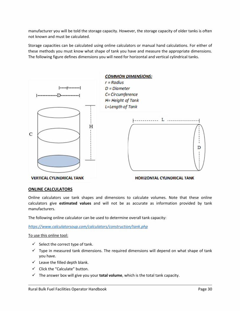
these methods you must know what shape of tank you have and measure the appropriate dimensions.
The following figure defines dimensions you will need for horizontal and vertical cylindrical tanks.
ONLINE CALCULATORS
Online calculators use tank shapes and dimensions to calculate volumes. Note that these online
calculators give estimated values and will not be as accurate as information provided by tank
manufacturers.
The following online calculator can be used to determine overall tank capacity:
https://www.calculatorsoup.com/calculators/construction/tank.php
To use this online tool:
Select the correct type of tank.
Type in measured tank dimensions. The required dimensions will depend on what shape of tank you have.
Leave the filled depth blank.
Click the “Calculate” button.
The answer box will give you your total volume, which is the total tank capacity.
Rural Bulk Fuel Facilities Operator Handbook Page 31
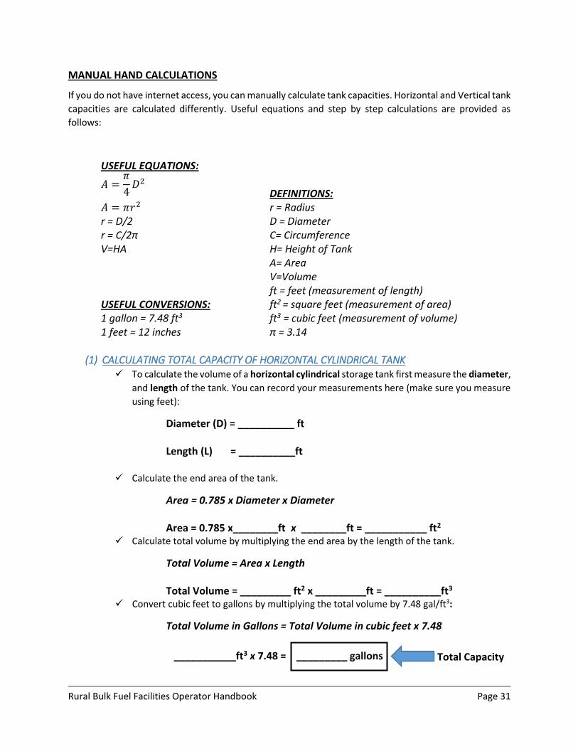
MANUAL HAND CALCULATIONS
If you do not have internet access, you can manually calculate tank capacities. Horizontal and Vertical tank
capacities are calculated differently. Useful equations and step by step calculations are provided as
follows:
USEFUL EQUATIONS:
𝐴 =𝜋
4𝐷2
DEFINITIONS: 𝐴 = 𝜋𝑟2 r = Radius r = D/2 D = Diameter r = C/2π C= Circumference V=HA H= Height of Tank A= Area V=Volume ft = feet (measurement of length) USEFUL CONVERSIONS: ft2 = square feet (measurement of area) 1 gallon = 7.48 ft3 ft3 = cubic feet (measurement of volume) 1 feet = 12 inches π = 3.14
(1) CALCULATING TOTAL CAPACITY OF HORIZONTAL CYLINDRICAL TANK
To calculate the volume of a horizontal cylindrical storage tank first measure the diameter,
and length of the tank. You can record your measurements here (make sure you measure
using feet):
Diameter (D) = __________ ft Length (L) = __________ft
Calculate the end area of the tank.
Area = 0.785 x Diameter x Diameter Area = 0.785 x________ft x ________ft = ___________ ft2
Calculate total volume by multiplying the end area by the length of the tank.
Total Volume = Area x Length Total Volume = _________ ft2 x _________ft = __________ft3
Convert cubic feet to gallons by multiplying the total volume by 7.48 gal/ft3:
Total Volume in Gallons = Total Volume in cubic feet x 7.48
___________ft3 x 7.48 = _________ gallons Total Capacity
Rural Bulk Fuel Facilities Operator Handbook Page 32
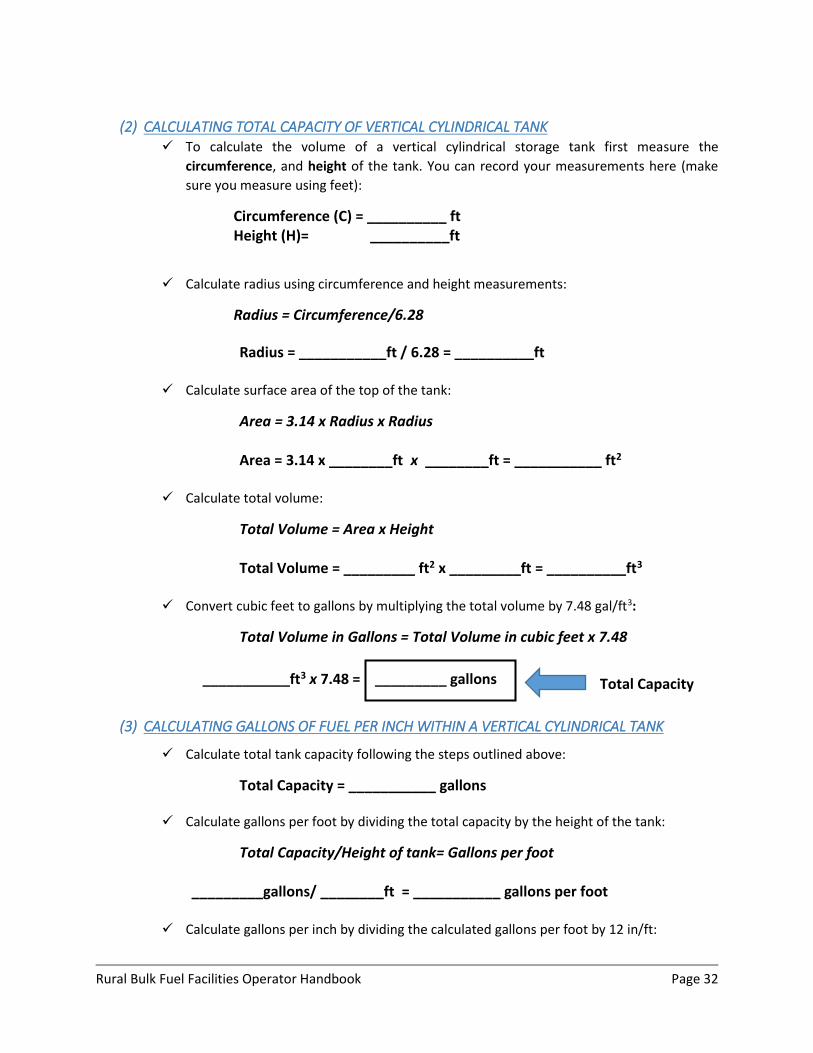
(2) CALCULATING TOTAL CAPACITY OF VERTICAL CYLINDRICAL TANK To calculate the volume of a vertical cylindrical storage tank first measure the
circumference, and height of the tank. You can record your measurements here (make
sure you measure using feet):
Circumference (C) = __________ ft Height (H)= __________ft
Calculate radius using circumference and height measurements:
Radius = Circumference/6.28
Radius = ___________ft / 6.28 = __________ft Calculate surface area of the top of the tank:
Area = 3.14 x Radius x Radius
Area = 3.14 x ________ft x ________ft = ___________ ft2
Calculate total volume:
Total Volume = Area x Height
Total Volume = _________ ft2 x _________ft = __________ft3
Convert cubic feet to gallons by multiplying the total volume by 7.48 gal/ft3:
Total Volume in Gallons = Total Volume in cubic feet x 7.48
___________ft3 x 7.48 = _________ gallons
(3) CALCULATING GALLONS OF FUEL PER INCH WITHIN A VERTICAL CYLINDRICAL TANK
Calculate total tank capacity following the steps outlined above:
Total Capacity = ___________ gallons
Calculate gallons per foot by dividing the total capacity by the height of the tank:
Total Capacity/Height of tank= Gallons per foot _________gallons/ ________ft = ___________ gallons per foot
Calculate gallons per inch by dividing the calculated gallons per foot by 12 in/ft:
Total Capacity
Rural Bulk Fuel Facilities Operator Handbook Page 33
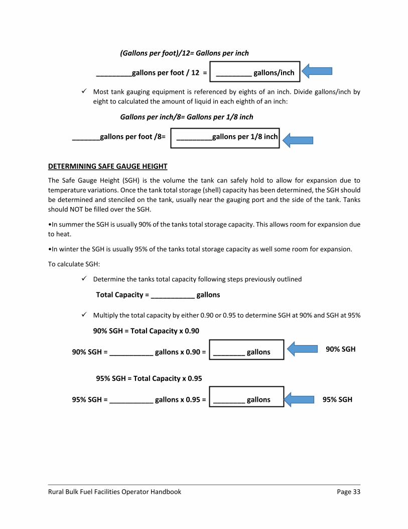
(Gallons per foot)/12= Gallons per inch _________gallons per foot / 12 = _________ gallons/inch
Most tank gauging equipment is referenced by eights of an inch. Divide gallons/inch by
eight to calculated the amount of liquid in each eighth of an inch:
Gallons per inch/8= Gallons per 1/8 inch
_______gallons per foot /8= _________gallons per 1/8 inch
DETERMINING SAFE GAUGE HEIGHT
The Safe Gauge Height (SGH) is the volume the tank can safely hold to allow for expansion due to
temperature variations. Once the tank total storage (shell) capacity has been determined, the SGH should
be determined and stenciled on the tank, usually near the gauging port and the side of the tank. Tanks
should NOT be filled over the SGH.
•In summer the SGH is usually 90% of the tanks total storage capacity. This allows room for expansion due
to heat.
•In winter the SGH is usually 95% of the tanks total storage capacity as well some room for expansion.
To calculate SGH:
Determine the tanks total capacity following steps previously outlined
Total Capacity = ___________ gallons
Multiply the total capacity by either 0.90 or 0.95 to determine SGH at 90% and SGH at 95%
90% SGH = Total Capacity x 0.90
90% SGH = ___________ gallons x 0.90 = ________ gallons
95% SGH = Total Capacity x 0.95
95% SGH = ___________ gallons x 0.95 = ________ gallons
90% SGH
95% SGH
Rural Bulk Fuel Facilities Operator Handbook Page 34
B. Tank Gauging and Temperature Corrections
Gauging product levels in the tank is critical for keeping accurate material inventory. Based on manual
gauge readings, the operator can determine the total volume of fuel remaining in the tank.
MANUAL GAUGE READINGS
Manual gauge readings are taken with a tape and plumb bob or dip stick, from a roof mounted vapor tight
gauge hatch. Manual gauge readings allow for the operator to determine remaining fuel levels and check
for water at the bottom of the tank.
Follow the procedure below for manual tank level measurements:
Use dark tapes to measure clear liquids such as diesel and light colored tapes to measure heavy fuels and crude oil.
Before taking measurements, check the tape for cracks and make sure the printing is legible.
Be sure to ground the tape before dropping the plumb bob into the tank and drop the bob slowly.
Lower the plumb bob until it just contacts the bottom of the tank.
Wind up the gauging tape and note the liquid line. If it is difficult to see, “gauging paste” may be used to clearly identify where the line of liquid cuts across the gauging tape.
Dip the tank until you get the same reading twice and then write down your reading.
DETERMINE GROSS GALLONS REMAINING
Once you have recorded your manual gauge reading you can determine the total volume of fuel remaining
within a tank. The total volume can also be called the gross volume within the tank and can be determined
using (1) tank capacity charts, (2) online calculators, or (3) manual hand calculations.
(1) Tank Capacity Charts Newer facilities with manufactured tanks should have capacity charts for each type of tank within
the facility. Tank capacity charts list incremental fuel depths and corresponding volumes of fuel
remaining in the tank. To use the charts simply find the depth that you measured during your
manual gauge reading and then write down the capacity listed for that depth.
(2) Online Tools If you do not have a tank capacity chart, there are online tools that you can use to generate
your own tank charts and calculate volumes. Online calculators use tank shapes and dimensions.
Note that these online calculators give estimated values and will not be as accurate as
information provided by tank manufacturers.
Tank Capacity Chart Using the following online calculator can help you develop a tank capacity chart. https://halltank.com/tank-charts/
Rural Bulk Fuel Facilities Operator Handbook Page 35
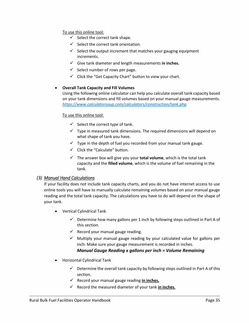
To use this online tool: Select the correct tank shape.
Select the correct tank orientation.
Select the output increment that matches your gauging equipment increments.
Give tank diameter and length measurements in inches.
Select number of rows per page.
Click the “Get Capacity Chart” button to view your chart.
Overall Tank Capacity and Fill Volumes Using the following online calculator can help you calculate overall tank capacity based on your tank dimensions and fill volumes based on your manual gauge measurements. https://www.calculatorsoup.com/calculators/construction/tank.php To use this online tool:
Select the correct type of tank.
Type in measured tank dimensions. The required dimensions will depend on what shape of tank you have.
Type in the depth of fuel you recorded from your manual tank gauge.
Click the “Calculate” button.
The answer box will give you your total volume, which is the total tank capacity and the filled volume, which is the volume of fuel remaining in the tank.
(3) Manual Hand Calculations If your facility does not include tank capacity charts, and you do not have internet access to use
online tools you will have to manually calculate remaining volumes based on your manual gauge
reading and the total tank capacity. The calculations you have to do will depend on the shape of
your tank.
Vertical Cylindrical Tank
Determine how many gallons per 1 inch by following steps outlined in Part A of this section.
Record your manual gauge reading.
Multiply your manual gauge reading by your calculated value for gallons per
inch. Make sure your gauge measurement is recorded in inches.
Manual Gauge Reading x gallons per inch = Volume Remaining
Horizontal Cylindrical Tank
Determine the overall tank capacity by following steps outlined in Part A of this
section.
Record your manual gauge reading in inches.
Record the measured diameter of your tank in inches.
Rural Bulk Fuel Facilities Operator Handbook Page 36
Calculate your Height-Diameter Ratio by dividing the recorded gauge height by the measured diameter of your tank.
Manual Gauge Reading/Measured tank Diameter= H/D Ratio
Look for your calculated ratio in the depth factor table in Appendix C and write down the corresponding depth factor.
Calculate gallons remaining by multiplying the depth factor by the total tank
capacity.
Gallons Remaining = Depth Factor x Total Tank Capacity
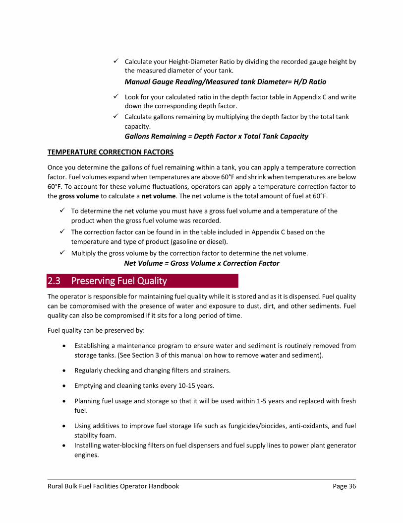
TEMPERATURE CORRECTION FACTORS
Once you determine the gallons of fuel remaining within a tank, you can apply a temperature correction
factor. Fuel volumes expand when temperatures are above 60°F and shrink when temperatures are below
60°F. To account for these volume fluctuations, operators can apply a temperature correction factor to
the gross volume to calculate a net volume. The net volume is the total amount of fuel at 60°F.
To determine the net volume you must have a gross fuel volume and a temperature of the
product when the gross fuel volume was recorded.
The correction factor can be found in in the table included in Appendix C based on the
temperature and type of product (gasoline or diesel).
Multiply the gross volume by the correction factor to determine the net volume.
Net Volume = Gross Volume x Correction Factor
2.3 Preserving Fuel Quality
The operator is responsible for maintaining fuel quality while it is stored and as it is dispensed. Fuel quality
can be compromised with the presence of water and exposure to dust, dirt, and other sediments. Fuel
quality can also be compromised if it sits for a long period of time.
Fuel quality can be preserved by:
Establishing a maintenance program to ensure water and sediment is routinely removed from
storage tanks. (See Section 3 of this manual on how to remove water and sediment).
Regularly checking and changing filters and strainers.
Emptying and cleaning tanks every 10-15 years.
Planning fuel usage and storage so that it will be used within 1-5 years and replaced with fresh
fuel.
Using additives to improve fuel storage life such as fungicides/biocides, anti-oxidants, and fuel
stability foam.
Installing water-blocking filters on fuel dispensers and fuel supply lines to power plant generator
engines.
Rural Bulk Fuel Facilities Operator Handbook Page 37
3 Periodic Maintenance Procedures
Proper maintenance will extend the useful life of your facility and reduce risk of costly and damaging spills.
Proper maintenance of your facility includes:
Routine Monthly and Annual Inspections
Required Testing
Part Replacements
Water Management
Proper Record Keeping
3.1 Inspections
Facility inspections are the best way to identify problems that could lead to system failures, leaks and
large spills. Inspections must be conducted on a regular basis in a standardized way. If a facility is manned,
informal inspections should be done on a daily basis when the operator walks through to open and close
the facility. Formal inspections should be completed and documented on a monthly and annual basis. The
operator or other personnel that are knowledgeable of the specific equipment and operating procedures
within the facility can complete monthly and annual inspections.
In addition to routine monthly and annual inspections, certain components of the facility should be
examined by a certified inspector.
The following provides more detailed descriptions on monthly inspections, annual inspections, and
certified inspector inspections.
A. Monthly Inspections
Monthly inspections should include assessments of the following items:
1. General Housekeeping
2. Safety Equipment
3. Security Equipment
4. ASTs and their appurtenances
5. Piping System (including all fittings, valves, and pumps)
6. Secondary Containment
7. Spill Prevention and Response Plans in Place
8. State/Federal Requirements are met
When conducting a formal inspection it is important to use a checklist. A general AST Facility monthly
inspection form is included in Appendix B. This form may be copied for your use and revised based on the
equipment and major components unique to your facility.
When filling out the checklist, be sure to document what the deficiency is and the corrective action
required to fix the problem. You may need to report significant problems to higher management.
Rural Bulk Fuel Facilities Operator Handbook Page 38
The following discussions provide more detailed descriptions of what to look for during your monthly
inspection based on the AST Facility Monthly Inspection Form provided in Appendix B.
(1) General Housekeeping Is the facility clean and clear of unnecessary items? It is important to keep facilities clean and free of
unnecessary items because clutter will hinder clean up in the event of a leak or spill. Large items such as
drums, lumber and other objects can damage pipes, dent tanks and provide homes for unwanted animals.
(2) Safety Equipment Is the safety equipment in place and are safety precautions followed? Safety at AST facilities is of the
utmost importance and can save lives, prevent injuries, and protect property and the environment. When
assessing your safety equipment be sure to check:
2a-Fire Extinguishers
There should be an adequate number of fire extinguishers in logical, appropriate
locations. Verify the fire extinguishers are easily accessible and fully charged. All tank
farm operators should have portable fire extinguisher training.
2b-No Smoking Signs “No Smoking” or “No Smoking Permitted” signs should be posted in strategic locations
within the facility.
2c-Danger and Warning Signs Danger and Warning signs: Individuals entering the facility should be warned of potential
dangers. Signs restricting entry to authorized persons should be posted in visible
locations. Other signs such as “Danger Flammable Liquids” should also be posted.
(3) Security Equipment AST facility owners and operators should employ security measures to prevent vandals, unwanted
individuals and animals from entering the tank farm. Aside from damage unwanted individuals may cause,
there are liability issues to consider. When assessing your security equipment be sure to check:
3a-Fencing Is there a fence around the facility? The fence must be intact and the gates must be
locked when unattended. Verify any chain-link fabric and barbed wire are not damaged.
3b-Lighting Does the facility have a lighting system? Lighting is important so workers can see their
way around the facility and to keep intruders out. Lights should provide adequate
illumination and be in good working order.
(4) Aboveground Storage Tanks (ASTs) and their Appurtenances Aboveground storage tanks are the most important component of an AST facility. They should be
maintained in good working condition. Be sure to fill out an inspection form for each tank. This applies to
all tanks within the facility. When assessing your AST be sure to check:
Rural Bulk Fuel Facilities Operator Handbook Page 39
4a-Tank Integrity Are there any visible leaks or drips from the tanks? Are there stains on the ground around
the base of the tank? Check seams and welds. All leaks must be stopped and repairs
made by a qualified technician with proper equipment.
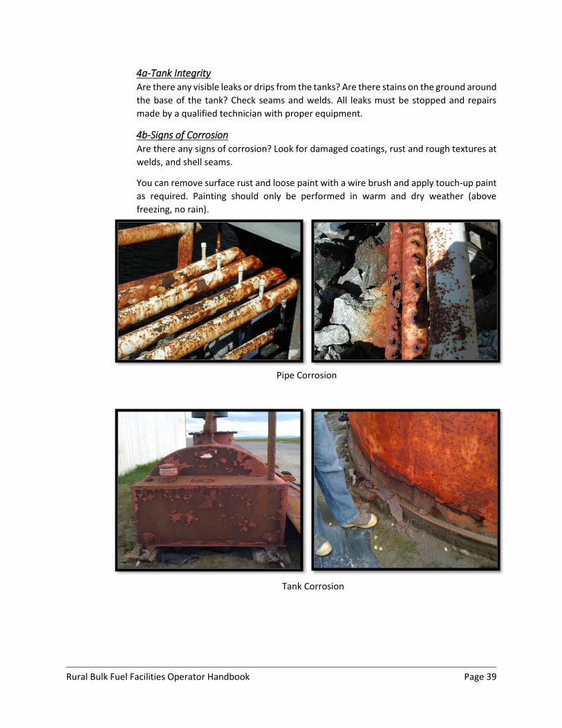
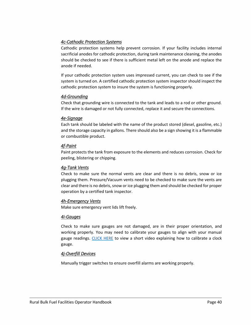
4b-Signs of Corrosion Are there any signs of corrosion? Look for damaged coatings, rust and rough textures at
welds, and shell seams.
You can remove surface rust and loose paint with a wire brush and apply touch-up paint
as required. Painting should only be performed in warm and dry weather (above
freezing, no rain).
Pipe Corrosion
Tank Corrosion
Rural Bulk Fuel Facilities Operator Handbook Page 40
4c-Cathodic Protection Systems Cathodic protection systems help prevent corrosion. If your facility includes internal
sacrificial anodes for cathodic protection, during tank maintenance cleaning, the anodes
should be checked to see if there is sufficient metal left on the anode and replace the
anode if needed.
If your cathodic protection system uses impressed current, you can check to see if the
system is turned on. A certified cathodic protection system inspector should inspect the
cathodic protection system to insure the system is functioning properly.
4d-Grounding Check that grounding wire is connected to the tank and leads to a rod or other ground.
If the wire is damaged or not fully connected, replace it and secure the connections.
4e-Signage Each tank should be labeled with the name of the product stored (diesel, gasoline, etc.)
and the storage capacity in gallons. There should also be a sign showing it is a flammable
or combustible product.
4f-Paint Paint protects the tank from exposure to the elements and reduces corrosion. Check for
peeling, blistering or chipping.
4g-Tank Vents Check to make sure the normal vents are clear and there is no debris, snow or ice
plugging them. Pressure/Vacuum vents need to be checked to make sure the vents are
clear and there is no debris, snow or ice plugging them and should be checked for proper
operation by a certified tank inspector.
4h-Emergency Vents Make sure emergency vent lids lift freely.
4i-Gauges
Check to make sure gauges are not damaged, are in their proper orientation, and
working properly. You may need to calibrate your gauges to align with your manual
gauge readings. CLICK HERE to view a short video explaining how to calibrate a clock
gauge.
4j-Overfill Devices
Manually trigger switches to ensure overfill alarms are working properly.
Rural Bulk Fuel Facilities Operator Handbook Page 41
4k-Check for Water
Check the tank for water through the gauge hatch. Note if there is water present and
remove if required. Refer to Section 3 of this manual for information on how and when
water can be removed from your tank.
4l-Foundations Check to see that the tank foundation is in good condition. If beams are used, are they
cracked or rotten. Is the foundation level? Are there signs the foundation is washing out
or damaged in other ways?
(5) Piping System (including all fittings, valves, and pumps) The piping system includes all fittings, joints, valves, and pumps used to move product through the facility.
When assessing your piping system be sure to check:
5a-Pipe Integrity Are there any drips, leaks or visible stains around pipe joints, pumps, meters, filters,
valves or hoses? Pay special attention to flex connections and look for joints that do not
line up.
Make note of damaged or leaking parts and replace as soon as possible.
5b-Signs of Corrosion Are there any signs of corrosion? Look for rust and rough textures at joints connecting
valves, pipes, and other fittings.
You can remove surface rust and loose paint with a wire brush and apply touch-up paint
as required. Painting should only be performed in warm and dry weather (above
freezing, no rain).
5c-Cathodic Protection A certified cathodic protection system inspector should inspect the cathodic protection
system to insure the system is functioning properly.
5d-Pipe Supports Are pipe supports adequate and in good condition? Check for sagging and cracking pipes
due to insufficient support and rusting or rotting pipe supports.
Note any issues, tighten or replace any loose, missing or damaged supports.
5e-Valves Are there any signs of leaks from the valves? Can the valves be turned completely on and
off to stop product flow? Are the valves protected from falling ice and snow, vehicle and
foot traffic? Verify all normally closed valves are locked in the closed position.
5f-Protection Check that the pipes are protected from falling ice and snow and from vehicular and foot
traffic.
Rural Bulk Fuel Facilities Operator Handbook Page 42
5g-Coatings If the pipes are coated, wrapped or painted, check for wear, tears and chipping. Clean
and repair pipe coating as required.
5h-Dispenser Unit Visually inspect the dispenser unit, hoses, nozzles and accessories. Look for leaks or
damage and replace any worn or non-operational accessory. Check that nozzles can be
turned off completely to stop the flow of product. Replace the fuel dispenser filter
annually, or if you notice a reduction in flows. CLICK HERE to view a short video explaining
how to replace a typical fuel dispenser filter.
5i-Control Panel Check the control panel for damage. Verify doors are closed tight. Verify operation of all
switches, buttons, and lamps. Test emergency shutoff switches. CLICK HERE to view a
short video explaining how to reset the power beaker. Repairs to the control panel must
be performed under the direction of a qualified technician (journeyman electrician).
(6) Secondary Containment The purpose of secondary containment is to hold any product should there be a spill. It is important that
this area be of sufficient size and have the ability to hold spilled oil.
6a-Dike Integrity Are there any cracks, holes or other damage to the containment dike walls? Repair as
needed.
6b-Liner Integrity Is the secondary containment area lined with a synthetic liner? Is the liner in good
condition or are there any rips, tears or non-essential holes in it? If the liner is not
waterproof, it will not hold spilled product. (Note: if the liner is holding rainwater, it is
probably in good condition and needs to be drained.)
6c-Clear of Water, Snow, Ice, or Vegetation Is the secondary containment clear of standing water, ice and snow? If water or ice is in
the containment area, there could be overflow if a tank failed. Snow could hide leaked
or spilled product and vegetation could damage liner material and hamper clean up.
If your facility uses tanks with built-in secondary containment such as double-wall, or
self-diked tanks, be sure to remove any water collected within the exterior walls.
(7) Spill Prevention and Response Plans in Place It is important to be prepared should a spill occur. Quick response can reduce the amount of oil spill thus
reducing health and environmental damage and saving money. Refer to Sections 6 and 7 of this manual
for more detailed discussions on spill prevention and response.
Rural Bulk Fuel Facilities Operator Handbook Page 43
7a-Response Plan Does the facility have a response plan and is it located at the facility? Each facility must
have plans to deal with emergencies and all the facility operators and workers should be
familiar with them.
7b-Response Equipment Is the response equipment located at the site and is it in good working order? Do
operators know how to use it? A minimum amount of oil spill response equipment
should be located in specific areas of the facility and operators should know where it is
located and how to use it. Appendix B includes a sample spill response equipment
checklist.
(8) State/Federal Requirements are Met
8a-ADEC Placards Placards include ADEC phone numbers and where to report spills. When inspecting the
facility make sure the signs are clearly posted.
8b-EPA SPCC and FRP Plans Depending on the location and size of your facility you may be required by the United
States Environmental Protection Agency (EPA) to have a Spill Prevention Control and
Countermeasures (SPCC). Some facilities will also need a Facility Response Plan (FRP).
Both plans must contain specific information. In the case of the SPCC, the document is
certified by a registered professional engineer and must be signed by facility
management indicating acceptance and implementation. When inspecting the facility,
check to see if a current copy of the required plan is easily accessible.
8c-USCG The United States Coast Guard (USCG) requires facilities that receive fuel from marine
vessels to submit a Letter of Intent to Operate and have an Operations Manual and
Facility Response Plan. When conducting the facility inspection, check for current copies
of these documents. The USCG also requires safety equipment such as fire extinguishers,
“Smoking Prohibited” signs, and response equipment and material to be located at the
facility.
B. Certified Inspections
Aside from routine facility inspections, it is a good practice to have ASTs examined by certified inspectors
on a regular basis. ASTs must be maintained and inspected to a recognized national standard. There are
two primary inspection standards depending on the tank. For horizontal tanks that were built in a shop
and then transported to the facility, the Steel Tank Institute Standard SP-001 is the primary standard to
use. For conventional vertical tanks built on site, the American Petroleum Institute Standard, API 653, is
the primary standard to use. These standards are designed for certified inspectors to follow for
comprehensive AST periodic internal and external inspections. Each standard has set inspection intervals
based on the size, configuration of the tank and the prior inspection results. These intervals should be
followed. More frequent or additional inspections should be considered if there is evidence of a leak,
Rural Bulk Fuel Facilities Operator Handbook Page 44
changes in the tank are evident or any other reason why the operator believes an internal inspection is
needed.
Facility operators are not expected to conduct such rigorous inspections. Many problems or potential
problems can be identified with simple monthly inspections previously discussed. However, with training
and certification for “HAZWOPER” and “confined space entry”, operators can conduct cursory internal
inspections. For these inspections, tanks should be emptied and cleaned and the inside examined for holes
and corrosion. Only trained and experienced persons should conduct internal inspections. Under no
circumstances should anyone else enter the tank.
If your system uses a cathodic protection system, you must have a National Association of Corrosion
Engineers (NACE) certified technician with proper equipment perform any testing. The cathodic
protection system should be tested annually, or as recommended by a qualified technician.
3.2 Required Testing
The integrity of ASTs and associated piping systems should be tested on a regular basis. Tests should be
performed by qualified technicians with proper equipment.
A. Tanks
You will not always be able to detect weaknesses in your tank from your monthly inspections. To ensure
that your tank walls are appropriate thicknesses a certified inspector can perform Ultra-sonic Thickness
testing. To test the strengths of welded seams, the tank can be vacuum tested, again by a certified
inspector.
External AST inspection by a certified tank inspector is recommended every evert 10 years and internal
AST inspection by a certified tank inspector is recommended every evert 20 years.
B. Pipeline Integrity Testing
If your facility receives fuel deliveries through barge services, and/or if it includes buried pipelines, annual
pressure tests must be performed. U.S. Coast Guard regulations require any piping between the marine
header connection and the secondary containment are to be hydrostatically tested annually. All other
piping in the tank farm should also be test annually.
All piping requiring testing must be tested prior to receiving new fuel deliveries for the year. Additional
testing may also be required if leaks are observed, piping is damaged, or significant repairs or alterations
have been made.
When pressure testing piping, take steps to protect pumps, dispensers, meters, filters and hoses from
high pressures. Close all isolation valves as required and remove any pressure relief valves from the
sections being tested. Testing pipes with air can be hazardous and is not recommended. Pipeline integrity
testing should only be performed using a hydrostatic test method.
Pressure tests can only be completed by qualified technicians with proper equipment. Be sure to obtain
test results and file with your records.
Rural Bulk Fuel Facilities Operator Handbook Page 45
3.3 Common Part Replacements
When replacing parts refer to the tank farm operation manual and the parts manufacture’s installation
manual. It is recommended to have common replacement parts on hand.
A. Filter Replacement
Fuel dispenser filters and fuel pipe system filters will need to be replaced when the fuel flow reduction is
noted or annually. CLICK HERE to view a short video explaining how replace a typical fuel piping system
filter.
B. Gaskets and Replacement Bolts
Over time, flange connections may develop leaks and require gasket replacement. CLICK HERE to view a
short video explaining how replace a typical flange gasket.
C. Strainers
Fuel strainers are typically installed on the inlet side of pumps. The strainers capture debris in the fuel
before it can enter and damage the pump. CLICK HERE to view a short video explaining how clean a fuel
strainer.
3.4 Water Management
A. Water Removal from Secondary Containment Dikes
Storm water that accumulates within a secondary containment area must be removed regularly. As a rule
of thumb, water should be removed after every heavy rainfall and any time the depth is greater than 2
inches. CLICK HERE to view a short video showing how to drain water from a secondary containment area.
Follow the steps outlined below to properly remove water from your containment area.
Only trained facility operators should perform storm water removal. Storm water levels must be
monitored and after every rain event. Remove water only during hours of daylight.
Look for any sheen on top of the water. If you notice sheen, it means there is some leaked fuel
product mixed with the water that you will have to remove prior to draining.
To remove fuel resting at the top of the water surface use sorbents to soak up the product. Be
sure to properly dispose of all used sorbents.
All used sorbent should be drained through a hand wringer. The water/fuel mixture should be
captured for proper disposal. Contaminated sorbents should be burned in a smart ash burner or
properly disposed of in the community landfill.
Pump water out of the containment area using a sump pump. The sump pump should include a
hose leading out of the diking area. Check the electric cords supplying power to the pump for any
frays or other damage. If the pump is not working, check the screen and make sure it is not blocked
by leaves or other debris.
Rural Bulk Fuel Facilities Operator Handbook Page 46
As soon as water has been removed, turn the pump off.
Make sure all leaves or other debris is removed from the containment area and properly disposed
of.
Record the date, time draining started, and time draining was completed in a water drainage log.
If there was sheen on the surface, record how you cleaned it up before you removed the storm
water.
B. Water Removal from Storage Tanks
When water collects at the bottom of a storage tank it can affect fuel quality and compromise the integrity
of the tank. As a rule of thumb it should be removed whenever it is detected. During inventory gauging,
you should always check for the presence of water in your tanks.
Water within storage tanks is removed using a tank drain at the bottom of the tank or a water draw from
the top of the tank. CLICK HERE to view a short video showing how to remove water from an AST. Follow
the steps outlined below to properly remove water from your AST.
(1) Tank Drain
Locate water drain valve, it should be at the bottom of one end of the tank.
Remove the locked endcap on the tank water drain valve.
Place a bucket at the end of the pipe to collect the water.
Open the valve and let water slowly flow out of the drain pipe into the bucket.
When water has been removed, close the drain valve and replace the end cap.
Check to see if all the water has been removed with gauging paste. If there is still water in the
tank, repeat steps outlined above.
Any water/fuel mixture collected from the tank water removal activity must be disposed of
properly. Diesel/water fuel mixtures can be allowed to separate, and the diesel fuel can be
disposed of in a smart ash burner. Gasoline/water fuel mixtures can be separated in a fuel water
separator.
(2) Water Draw
Locate water draw connection at the top of the tank.
Remove threaded end cap.
Install hand pump and manually pump water out of the tank into a bucket.
Check to see if all the water has been removed with gauging paste. If there is still water in the
tank keep pumping.
Once all the water has been removed, remove the hand pump and replace the threaded end cap.
Any water/fuel mixture collected from the tank water removal activity must be disposed of
properly. Diesel/water fuel mixtures can be allowed to separate, and the diesel fuel can be
disposed of in a smart ash burner. Gasoline/water fuel mixtures can be separated in a fuel water
separator.
Rural Bulk Fuel Facilities Operator Handbook Page 47
3.5 Recordkeeping
Records of all activities pertaining to the facility should be kept on location. These include but are not
limited to:
COPIES OF INSPECTIONS
Operator inspections
Government inspections
AST inspection reports
Cathodic protection inspection reports
MAINTENANCE RECORDS
Any major work done at the facility or on the tanks
Annual hydrostatic test results
As-built facility plans
OPERATOR TRAINING REPORTS
Any training courses the operator attends
REPORTS OF SPILLS AT THE FACILITY
Spill Prevention and Countermeasures (SPCC) Plans (EPA)
Facility Response Plans (EPA, USCG)
Letter of Intent to Operate (USCG)
Operation Manual (USCG)
Declaration of Inspection (USCG)
Spill Notification Placard (ADEC)
FUEL INVENTORY RECORDS
Fuel deliveries
Manual gauging records
Retail sales
GOVERNMENT REQUIRED RECORDS
Spill Prevention and Countermeasures (SPCC) Plans (EPA)
Facility Response Plans (EPA, USCG*)
Letter of Intent to Operate (USCG*)
Operation Manual (USCG*)
Declaration of Inspection (USCG*)
Spill Notification Placard (ADEC)
*USCG requirement if fuel is received by a marine vessel.

Rural Bulk Fuel Facilities Operator Handbook Page 48
4 Common Tank/Facility Failures
Facility failures can cause major economic, environmental, and health impacts. This section highlights
common causes and sources of leaks and spills and highlights the importance of proper operation and
maintenance.
A. Operator Errors
It is the facility owner’s responsibility to provide training opportunities for the operator. Once properly
trained, it is the operator’s responsibility to ensure that fuel transfer procedures are followed and that
the facility is regularly inspected, tested, and maintained. The operator must take pride in the operation
of their AST facility.
Poor transfer procedures such as not regularly monitoring tank levels, not properly isolating tanks through
valve control, and not maintaining proper contact between delivery personnel can lead to fuel spills and
leaks at the facility. Risks associated with poor transfer procedures can be avoided by having a clear
written procedure that is followed every time there is a fuel transfer. Operators should know which valves
close which tanks, which valves are typically left open to allow flow, and which valves are typically left
closed.
Facilities should be inspected on a regular basis and the operator should keep records of all inspections.
One of the most common issues that leads to a failure within the facility is when deficiencies are noted
during an inspection, but the proper corrective action is not taken. If a part needs replaced, replace it. It
is much cheaper in the long run to replace single components than a whole facility.
B. AST Problems
Monthly and annual inspections can help the operator identify issues that can lead to tank failures. It is
important to take these inspections seriously. The most common culprits leading to tank failures include:
Interior Corrosion: One of the main causes of corrosion on the interior of the tank is from water
that settles at the bottom of the tank. It is important to routinely check for and remove water
from your ASTs to prevent corrosion.
Exterior Corrosion: Damage to the tank exterior coatings and direct contact with the ground can
lead to surface rust and pitting of the tank exterior shell. Tank exterior shells should not be
allowed to contact the ground. Any signs of rust or damage to the tank exterior coating should
be quickly repaired.
Inadequate Tank Foundations: Tanks that are not supported on tank saddles and a steel skid
can roll over if the tank foundation and blocking is damaged. Tanks that are not supported on a
stable foundation can over time, settle into the ground, leading to exterior tank corrosion from
contact with the ground.
Improper Venting: Improper tank venting can cause tanks to collapse in on themselves or
rupture. As fuel levels and temperatures change in an AST, vapor pressures inside the tank can
Rural Bulk Fuel Facilities Operator Handbook Page 49
increase or decrease. Vents allow air to flow into the tank and vapors to flow out of the tank and
maintain a safe tank interior pressure.
During routine inspections, you may not be able to identify weakening tank walls or seams, or deficiencies
in cathodic protection systems. It is important to have your facility tested and checked by certified
inspectors.
C. Facility Piping Problems
Failures within the piping system can be managed by performing routine inspections and annual pressure
tests. The most common culprits leading to failures in the piping system include:
Exterior Pipe Corrosion: Pipes that are in direct contact with the ground, have damaged coatings,
or are buried without corrosion protection, have a risk for corrosion.
Inadequate Pipe Supports: Sagging or over-stressed pipes are prone to stress cracking, especially
at threaded pipe joints and fixed connections.
Flex Fittings: Flex fittings can be over stressed and fail from pipe misalignment or pipe expansion
from temperature changes.
Threaded Pipe Joints: Threaded pipe joints require a thread sealant to seal the pipe joint. As the
sealant degrades over time or if the pipe joint is overstressed, threaded pipe joints can start to
leak. Threaded joints should be routinely checked for leaks and repaired if required.
Vehicle Damage: Fuel pipe systems are often installed next to vehicle traffic areas. Improperly
marked fuel pipe systems can be easily damaged.
Valve Failures: Damaged or worn out valves that leak or do not properly open and close can
have serious impacts on how the system is operated, leading to fuel spills. If a valve is not
shutting all the way, the operator cannot isolate parts of the system.
D. Secondary Containment Problems
Secondary containment is the last line of defense in the event of a large spill. If your tank farm’s secondary
containment is damaged, and fuel products are spilled in the containment area, the area around the tank
farm will be contaminated. The most common problems that can affect the functionality of your
secondary containment system include:
Inadequate or No Secondary Containment: Single-wall fuel storage tanks are required to have
a secondary containment system that will hold the entire tank’s contents plus additional storage
capacity for rainwater.
Torn or Punctured Secondary Containment System Liners: A damaged liner will not be able to
capture a fuel spill. Product will leak through tears and holes and flow out of the containment
area. If the secondary containment system does not hold water after a rain event, some part of
the liners is damaged.
Rural Bulk Fuel Facilities Operator Handbook Page 50
Damaged Dike Walls: Dike walls can be damaged from vehicles, heavy equipment, ground
settlement and erosion from storm events. Make sure you are inspecting your walls and
repairing any breaches.

Rural Bulk Fuel Facilities Operator Handbook Page 51
5 Safety
AST facilities have several potential hazards. Operators should know what safety measures to take to
avoid accidents and injuries from these hazards. Major topics covered under this section include:
Fire and Explosion Safety/Prevention
Facility Safety
Personal Safety
5.1 Fire and Explosion Safety/Prevention
One of the biggest risks at a bulk fuel facility is that of fire or explosions caused by spills, pent up fumes,
or numerous other factors. Fires and explosion risks can be greatly reduced by following the procedures
outlined in previous sections. However, certain extra measures must still be taken to protect personnel
and customers from accidental fuel or fume ignition.
A. Fire Protection
Petroleum products are flammable and many are also explosive if vapors are allowed to build up.
Mitigating fire and explosion risks start with the operator but everyone involved with the facility, all the
way down to the final end-users, must be involved with maintaining a safe facility.
Facilities are designed and built with fire safety involved and are required to receive approval
from the State Fire Marshal. Do not make any modifications to the facility layout without first
consulting with the Fire Marshal or other authority having jurisdiction over your facility.
Ensure that fire extinguishers are rated to extinguish “B” type fires. Fire extinguishers will have a
letter code (for example: “ABC”) written on the label which corresponds to the different types of
fires they are rated to extinguish. Place fire extinguishers in strategic locations throughout the
facility and inspect them monthly for proper charge and pressure. Document inspections on the
attached inspection card. All tank farm operators should be trained on how to use a portable fire
extinguisher.
Do not smoke in or around the AST facility. Post signs in conspicuous places stating that there is
no smoking allowed throughout the facility. Ensure that customers do not smoke in or around
dispensing facilities.
Do not allow open flames or potential spark sources in or around the AST facility. Sparks or open
flames can ignite flammable vapors and cause an explosion.
Do not store nonessential items or materials such as empty gas cans, jerry jugs, used rags, or other
items that can start or spread a fire at the AST facility.
Electrical Grounding
Proper grounding of AST facilities will help to mitigate accidental sparking due to static electricity buildup.
Operators should periodically inspect grounding systems to ensure a continuous electrical connection
Rural Bulk Fuel Facilities Operator Handbook Page 52
between tanks, pipes, electrical equipment, etc. and the facility’s grounding system. Improper grounding
of equipment can lead to explosions if fuel vapors build up and are ignited by a spark.
Hazard Communication Safety Data Sheets
The United States Occupational Safety and Health Administration (OSHA) requires that manufacturers,
distributors, or importers of chemicals, including petroleum products, provide Hazard Communication
Safety Data Sheets (SDS) (formerly known as Material Safety Data Sheets, or MSDS) that are kept onsite
for each product stored at the facility. Employees should know their locations and the hazards associated
with each product.
Additional information on SDS can be found at the following links:
https://www.osha.gov/Publications/OSHA3493QuickCardSafetyDataSheet.pdf
https://www.osha.gov/Publications/OSHA3492QuickCardLabel.pdf
https://www.osha.gov/Publications/OSHA3491QuickCardPictogram.pdf
5.2 Facility Safety
Maintaining a safe AST facility goes beyond just preventing slips, trips, and falls. Ensure that equipment is
properly labeled, safety devices are functionally maintained, and proper communication is maintained.
General Operation and Safety Procedures
Check that signs and labels are legible and in clear view for both facility operators and customers.
If signs are dirty or worn, clean or replace them accordingly.
Maintain open communications within the facility and with local emergency services.
o Utilize two-way radio communication with other AST facility personnel and emergency
services. Cell phone communication can be unreliable at times.
o Keep an open channel with local emergency services.
Maintain safety equipment in proper working order.
o Verify that tank overfill devices, level indicators, and alarms are functioning as intended.
o Always know where emergency shutoff switches are located. Ensure that they are clearly
marked.
o Fuel shutoff valves and their locations should also be clearly marked.
Maintain facility security. Keep all unauthorized people out of the facility unless they are escorted
by facility employees.
o Ensure that all gates are closed and locked when the facility is not in use.
o Change burned out lights as soon as they are spotted.
o Verify that valves, tank lids, dispensing equipment, etc. are properly secured and locked
when not in use.
Rural Bulk Fuel Facilities Operator Handbook Page 53
5.3 Personal Safety
Personal safety is for more than just keeping you safe. Beyond protecting you from fuel spillage, cuts,
object drops, or the weather, it also helps other people see where you are so that they can avoid you
while operating equipment, or make sure that they are performing their duties in a safe manner.
Safety Equipment/Concepts
Wear shoes with an OSHA certified safety toe.
Wear eye protection when appropriate, particularly during fuel transfers.
Wear hearing protection when appropriate.
Wear gloves when working in cold temperatures or when handling materials or objects that may
cause injury.
Keep walkways and stairs free of ice and debris to avoid trips and falls.
Make yourself aware of your surroundings. If someone is operating equipment, maintain verbal
communications and eye contact as appropriate.
Do not drink alcohol when on duty.
Additional information on safety equipment can be found at the following link:
https://www.osha.gov/OshDoc/data_Hurricane_Facts/construction_ppe.pdf
Climbing Onto Tanks and Tie-on Mechanisms
Sometimes it will be necessary to climb onto the tank to open inspection hatches, check safety valves,
obtain fuel samples, or perform visual tank inspections. If use of a ladder is required to climb onto the
tank the operator will need to properly secure the ladder base and use a spotter to ensure proper climbing
safety. If the tank is not equipped with a fall protection guardrail, the operator must wear a fall protection
harness and maintain 100% tie-off at all times. This means that there are two attachment points on the
harness, one of which must be clipped in to ensure proper protection against falls.
Additional information on ladder and fall protection safety can be found at the following link:
https://www.osha.gov/Publications/OSHA3903.pdf
Confined Space Entry
It may sometimes be necessary for AST operators to enter confined spaces. Entry into confined spaces
should not be taken lightly. This is a two-person operation that requires certain techniques to be followed
so that in the event of an emergency the worker entering the confined space can be removed quickly, and
without requiring the spotter to enter the space. Only personnel certified to enter confined spaces may
perform work that requires them to enter into confined spaces. If you are unsure if a space is classified as
a “confined space” do not risk it!
More information on confined spaces can be found at the following link:
Rural Bulk Fuel Facilities Operator Handbook Page 54
https://www.osha.gov/OshDoc/data_Hurricane_Facts/confined_space_permit.pdf
Basic First Aid
Quick responses to accidents can save lives and prevent serious injuries. It is a good idea for AST facility
operators to have basic first aid training.
First aid training should include basic emergency response and cardiopulmonary resuscitation
(CPR), if you have the proper training.
Facility personnel should know the location of first aid kits and be familiar with their contents.
Some basic first aid responses for fuel incidents include:
Vapor inhalation – move to fresh air immediately
Skin contact with fuel – remove affected clothing and wash skin with clean water
Eye contact with fuel – flush with clean water and seek medical help
Ingestion of fuel – do NOT induce vomiting, seek immediate medical help
For more direction on what to do in the event of a fire, contact with skin, eyes or inhalations,
refer to SDS data sheets specific to the products within your facility.
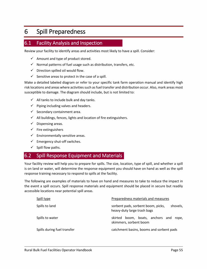
Rural Bulk Fuel Facilities Operator Handbook Page 55
6 Spill Preparedness
6.1 Facility Analysis and Inspection
Review your facility to identify areas and activities most likely to have a spill. Consider:
Amount and type of product stored.
Normal patterns of fuel usage such as distribution, transfers, etc.
Direction spilled oil would flow.
Sensitive areas to protect in the case of a spill.
Make a detailed labeled diagram or refer to your specific tank farm operation manual and identify high
risk locations and areas where activities such as fuel transfer and distribution occur. Also, mark areas most
susceptible to damage. The diagram should include, but is not limited to:
All tanks to include bulk and day tanks.
Piping including valves and headers.
Secondary containment area.
All buildings, fences, lights and location of fire extinguishers.
Dispensing areas.
Fire extinguishers
Environmentally sensitive areas.
Emergency shut-off switches.
Spill flow paths.
6.2 Spill Response Equipment and Materials
Your facility review will help you to prepare for spills. The size, location, type of spill, and whether a spill
is on land or water, will determine the response equipment you should have on hand as well as the spill
response training necessary to respond to spills at the facility.
The following are examples of materials to have on hand and measures to take to reduce the impact in
the event a spill occurs. Spill response materials and equipment should be placed in secure but readily
accessible locations near potential spill areas.
Spill type Preparedness materials and measures
Spills to land sorbent pads, sorbent boom, picks, shovels, heavy-duty large trash bags
Spills to water skirted boom, boats, anchors and rope, skimmers, sorbent boom
Spills during fuel transfer catchment basins, booms and sorbent pads
Rural Bulk Fuel Facilities Operator Handbook Page 56
Spills from leaks in the system sorbent pads, drip pans, catchment basins, repair and patch materials
A. Spill Response Equipment and Materials Checklist
Appendix B includes a list of basic equipment and materials that should be kept on hand and readily
available to respond to spills. You can use these lists to keep track of what you have in your spill kit to help
you know when you need to order new supplies. These lists are basic and should be modified for your
individual facility per your facilities SPCC plan.
All employees should know the location of all spill response equipment and materials and know how
to use the equipment and materials in the case of a spill.
6.3 Operator Preparedness Training
The severity of spills can be minimized if operators are properly trained in facility operations and spill
response, including proper use of spill response equipment and materials. It is recommended that
facilities develop written training plans for each of their operators.
Areas of spill preparedness training include:
Operations: Operators must be qualified and competent for conducting normal routine
operations.
Inspections: Operators must be familiar with the facility and its operations. This will enable them
to conduct regular inspections and be able to recognize problems.
Maintenance: Operators must be qualified to perform regular preventive maintenance. When
necessary, a specialist should be called in.
Spill Preparedness: Operators must be trained in procedures for storage, maintenance,
inspection and periodic testing of oil spill response equipment and materials.
Spill Response: Operators must be trained in deployment of spill response equipment and
materials, safety, first aid, spill reporting, and response actions. At a minimum, they should
participate in annual drills.
Hazardous Material Handling (HAZMAT): Operators must be trained in safety, be aware of
potential hazards and proper fuel handling procedures.
First Aid/Cardiopulmonary Resuscitation (CPR): Operators should have basic first aid training
with emphasis on identifying and responding to health emergencies due to fuel exposure. It is a
good idea for operators to know CPR.
6.4 Spill Response Plans
Facility spill response plans should be working documents. Operators and responders should be familiar
with their location and contents. These plans should:
List whom to notify, along with telephone numbers, of a spill or call for help.
Describe the actions to be taken in the event of a spill.
Describe deployment strategies for spill response equipment and materials.
Rural Bulk Fuel Facilities Operator Handbook Page 57
Discuss the protection of critical and sensitive areas.
Describe the recovery of spilled product.
Describe the proper management of recovered product and contaminated soil and other
materials such as sorbents.
Discuss safety considerations.
6.5 Community Spill Response Program
The Alaska Department of Environmental Conservation (ADEC) provides immediate response capability in
many villages and communities in Alaska. This service is available because of partnership agreements with
local communities, spill response cooperatives and response action contractors. The intent of the
agreements is to give local communities and villages the ability for immediate spill response. This is
necessary to immediately contain and control releases to reduce the impact on public health and the
environment as other responders or resources are traveling to the site. These agreements include
stationing response packages in specified areas and providing training to local responders in equipment
use.
Each response package is under the control of the State On-Scene Coordinator for the area in which it is
located. Packages include spill response material and equipment for the types of hazards that exist in the
area. An example of a spill response container inventory is included at the end of this section. In the event
of a spill, the situation will be assessed and the response managed by ADEC area staff or by personnel
responsible under a “Local Response Agreement.” More information concerning the Community Spill
Response Program can be found here: http://dec.alaska.gov/spar/ppr/local_resp.htm

Rural Bulk Fuel Facilities Operator Handbook Page 58
7 Spill Response and Reporting
7.1 Detecting Oil Spills
Sometimes oil spills are not as easy to detect, as one would think. The following are some tips to help
determine if you have spills or leaks at your facility:
Visible spilled product on the ground.
Sheen on water.
There is a smell of fuel in the air.
The inventory does not reconcile.
Dead or oiled fish, birds or small mammals.
Dead vegetation around the facility.
There is a smell or taste in the drinking water.
Sounds such as spraying liquids, a high pitch release from a pressure vessel, etc.
Staining on the outside of tanks or pipes, especially at seams or joints.
Spills can happen anywhere but most often from tops of tanks during overfills, at the bottom of tanks due
to corrosion, and from any connection to the tank from pipes. Pipes can leak from any connection or valve.
Dispensing areas and fuel transfer points require additional attention due to the risk of operator error.
7.2 Spill Response
When you determine that you have a spill at your facility, immediate action must be taken. This section is
a description of recommended steps to take and whom to notify. Appendix B includes a “Spill Response
Checklist” which is an abbreviated version of this section. The checklist may be copied, modified for your
facility, and used as you see fit.
Note: The procedures outlined should be considered recommendations. Every spill is different and your
response should be guided by your capabilities and equipment limitations.
A. Initial Defense Actions
1) Survey the incident. From a safe distance, using senses of sight, hearing and smell, take note of: Source of release (tank, pipe, valve, drum, etc.).
Product spilled - look at labels and markings (gasoline, diesel, etc.).
Occupied buildings that may be threatened.
Public areas and environmentally sensitive areas that may be threatened.
Safety First – Human Lives and Safety are the Most Important.
2) Call for help. Let others know where you are, what you are doing and what they can do to help. This may save your life as well as reduce the impact from the spill. Call:
Rural Bulk Fuel Facilities Operator Handbook Page 59
Facility Owner or Manager
Local Fire Department
Local Responders
Local Law Enforcement
Local Medical Personnel
3) Analyze the incident
Collect hazard information on product spilled (refer to SDS sheets).
Predict the likely behavior of the spilled product (flow direction, etc.) as well as what may have happened to the source container.
Estimate the extent of the spill and the potential for harm to humans and the environment.
4) Protect the public
Keep non-emergency and unauthorized personnel away from the facility and the spill area.
Evacuate areas downwind and stay upwind of the spill – fumes can cause safety and health problems.
Control the scene and ribbon off the spill area to keep the public away from the spill.
Know when to stay away (explosive hazard, etc.).
Have public service announcements made to ask others to avoid the facility and spill area.
5) Plan a response
Identify response objectives based on the analysis.
Determine initial responder and equipment needs.
If needed, contact ADEC for access to additional response equipment located in “Local Response Containers.”
Conduct a safety briefing with all responders.
6) Protect yourself
Wear appropriate personal protective gear. o Hardhat o Rubber and/or safety toed boots o Respirator o Disposable suit or rain gear o Eye protection o Neoprene gloves
Watch out for symptoms of heat and cold stress.
Establish personnel decontamination station prior to entry.
7) Verify spill source–determine and verify where the spill is coming from.
Tanks o Check vents for evidence of spill product from overfill or heat expansion.
Rural Bulk Fuel Facilities Operator Handbook Page 60
o Look at tank shell seams for rupture, leaking welds, missing bolts or rivets, or any other damage or flaws.
o Check the shell to bottom seam for corrosion, leaking welds or other damage. o Check tell-tale pipes or other leak detection devices. o Check man-way covers and other tank penetrations for leaks.
Piping o Check to see if any pipes are cracked or broken. o See if the valves are in the correct position – open or closed. o Look for broken or leaky joints. o Check connections with the tank.
Other sources – Look around to see if the spilled oil could be coming from another source such as
a vehicle parked on the premises, or drums stored near or in the facility.
Planned Response Actions – Use the “BUDDY SYSTEM”
8) Control the spill
Stop transferring fuel immediately if the spill occurs during a transfer.
Know the location of all emergency shut off equipment, both electrical and mechanical.
Close the valves upstream of the leak to stop the flow of product.
Place buckets or basins under a leak from a pipe or valve.
Apply a temporary patch over a leaky pipe or tank.
If a spill is from a damaged tank, transfer fuel to another tank.
9) Contain the spill as soon as possible – the quicker the spill is contained, the less potential for
danger to humans and less impact to the environment
Use spill response tool kits – shovels, absorbents, etc.
Follow deployment strategies outlined in the Spill Response Plan.
For winter spills o Pile snow to form a dike around the spilled product
Dig ditches in ice and line with plastic to contain the spill
For summer spills o Use dirt and mud to form a dike around the spilled product
o Dig a ditch and line with plastic to divert product way from streams or other bodies of water and to collect fuel
Pay particular attention to sensitive areas o Drinking water sources o Residential areas o Commercial areas o Fish and wildlife habitat o Culturally sensitive areas
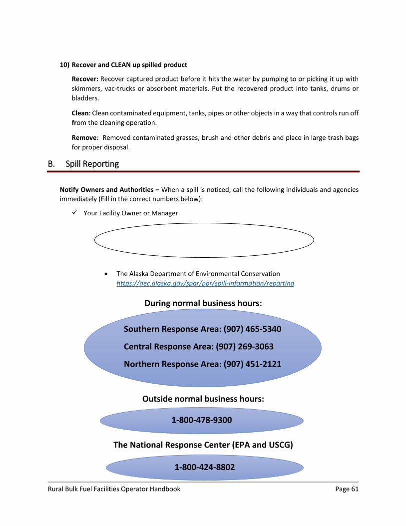
Rural Bulk Fuel Facilities Operator Handbook Page 61
10) Recover and CLEAN up spilled product
Recover: Recover captured product before it hits the water by pumping to or picking it up with
skimmers, vac-trucks or absorbent materials. Put the recovered product into tanks, drums or
bladders.
Clean: Clean contaminated equipment, tanks, pipes or other objects in a way that controls run off
from the cleaning operation.
Remove: Removed contaminated grasses, brush and other debris and place in large trash bags
for proper disposal.
B. Spill Reporting
Notify Owners and Authorities – When a spill is noticed, call the following individuals and agencies
immediately (Fill in the correct numbers below):
Your Facility Owner or Manager
The Alaska Department of Environmental Conservation
https://dec.alaska.gov/spar/ppr/spill-information/reporting
During normal business hours:
Outside normal business hours:
The National Response Center (EPA and USCG)
Southern Response Area: (907) 465-5340
Central Response Area: (907) 269-3063
Northern Response Area: (907) 451-2121
1-800-478-9300
1-800-424-8802
Rural Bulk Fuel Facilities Operator Handbook Page 62
Make sure signs with appropriate contact numbers are visibly posted in the facility. Also make sure
notification signs are visible so others can see them in the event of a spill when the facility is closed.
Notifications signs are available from ADEC free of charge.

Rural Bulk Fuel Facilities Operator Handbook Page 63
8 Regulatory Requirements and Compliance
This section summarizes the various requirements from State and Federal agencies. Some of these
regulations may not apply to your particular facility. It is the AST Operator’s responsibility to familiarize
themselves with the applicable regulatory requirements specific to their facility.

Rural Bulk Fuel Facilities Operator Handbook Page 64
U.S. Environmental Protection Agency (EPA)
Requirements Overview
Spill Prevention Control and Countermeasure (SPCC) and/or Facility Response Plans
Personnel training in the prevention, containment, removal and disposal of spilled oil
Inspection and maintenance program to a recognized industrial standard
Proper selection and construction of spill prevention systems which include dikes, liners, pumps, absorbent boom, etc.
Environmental Protection Agency Law: Clean Water Act
Regulation: 40 CFR 112: Oil Pollution Prevention
https://www.epa.gov/sites/production/files/2014-04/documents/b_40cfr112.pdf
Applicability: Owners or operators of facilities engaged in drilling, producing, gathering, storing, processing, transferring or consuming oil or oil products, providing:
The facility is non-transportation related
Aggregate aboveground storage capacity is 1,320 gallons and the minimum container size is 55 gallons
Facilities, which due to their location, could reasonably expect spilled oil to reach waters of the United States
A. Spill Prevention, Control and Countermeasures (SPCC) Requirements: The SPCC regulation specifies several major oil spill control requirements:
Secondary Containment: diking or other structural containment or their equivalent must be provided.
It must be large enough to hold the contents of the largest tank plus allowance for precipitation
(usually 10% of the largest tank). Diked areas must be sufficiently impermeable to contain spilled oil.
Tank Installations: must be fail-safe engineered to prevent spills. Tanks must have at least one of the
following:
High level liquid level alarms, audio or visual
Rural Bulk Fuel Facilities Operator Handbook Page 65
High level liquid cutoff device
Direct audible or code signal communication between gauge and pump station
Fast response system for determining fuel level, this would be a computerized system or direct visual gauges
Tank Material and Construction: must be compatible with stored product and local conditions such
as temperature.
Fencing, Locks and Lighting: Oil storage facilities must be fenced and the gate locked or guarded when
the facility is unattended. Facility type and location must be considered when selecting and installing
lighting. It should prevent vandalism and help detect spills at night.
Operations and Maintenance: Aboveground tanks, foundations, and supports must have periodic
integrity tests, using methods such as hydrostatic testing, visual inspection or non-destructive shell
thickness testing. Records of test results must be kept so they may be compared and variances
identified.
Piping Requirements: Buried piping must have a protective coating or wrapping and must be
cathodically protected. All aboveground valves and piping must be examined regularly and
assessments made. Underground piping that becomes exposed must be inspected.
Training Requirements: AST facility owners and operators are responsible for training oil handling
personnel in operations and maintenance of equipment to prevent discharges, discharge procedures,
protocol and Spill Prevention, Control and Countermeasure Plans.
Facility owners and operators are liable for civil penalties for SPCC violations.
B. SPCC Plan Requirements: AST facilities are required to prepare SPCC Plans.
https://www.epa.gov/oil-spills-prevention-and-preparedness-regulations
These are procedural and contingency plans that play an important safety role for facility owners and operators. In case of a spill, it is necessary to have a well thought-out and systematic response and cleanup plan that can be implemented immediately.
SPCC plans must be written and implemented before beginning operations.
Plans must be kept at the facility if it is in operation at least four hours a day and must be available
for EPA inspection.
Plans must be prepared in accordance with good engineering practice and certified by a registered
professional engineer.
Plans must be reviewed and updated every five years.
Plans must discuss spill prevention, staff training, inspections, security, spill reporting, equipment and
operations.
Rural Bulk Fuel Facilities Operator Handbook Page 66
SPCC plans must describe training, equipment testing, and periodic unannounced drills. They must
also describe facility personnel response actions to be carried out under the plan to ensure facility
safety and to mitigate or prevent a discharge or the substantial threat of a discharge.
Plans must provide for appropriate containment, drainage control structures or equipment at the
facility to prevent discharged oil from reaching navigable waterways.
A link of the checklist that the EPA uses when reviewing SPCC plans is included:
https://www.epa.gov/sites/production/files/2014-
07/documents/onshore_production_checklist_june_2014_for_web.pdf
C. Facility Response Plan: In addition to a SPCC plan, certain facilities need to prepare a Facility Response
Plan (FRP).
Applicability: Facility Response Plans must be prepared by owners or operators of non-transportation related facilities that, because of their location, could reasonably cause “substantial” harm to the environment by discharging oil into or on navigable waters or adjoining shorelines. EPA considers a facility to pose a potential for causing substantial harm if it transfers oil over water to or from vessels and has a total storage capacity greater than or equal to 42,000 gallons. EPA has the authority to require a facility to prepare or revise a Facility Response Plan at their discretion. Factors that the EPA considers when evaluating a facility include:
Oil storage capacity
Type of transfer operation
Secondary containment
Proximity of fish and wildlife and sensitive environments
Proximity of drinking water intakes
Spill history
Age of oil storage tanks
Other site specific considerations determined relevant by the EPA
Petition from any person, including the general public, who believes your facility has the potential to cause substantial harm to the environment according to the above-listed considerations
A link to the flowchart the EPA provides for determining whether a Facility Response Plan is needed is
included:
https://www.epa.gov/sites/production/files/2014-04/documents/h_frp_c1_cfr-2013-title40-vol23-
part112_39.pdf
Plan Requirements: A Facility Response Plan (FRP) describes preparations, procedures, training and actions for responding to oil discharges at a facility. FRP’s must:
Be submitted to the EPA for review and approval.
Rural Bulk Fuel Facilities Operator Handbook Page 67
Include an emergency action plan that describes personnel and procedures in place to respond to spills.
Describe external response resources and arrangements for responding to a worst case discharge.
Plan for the worst-case scenario.
Provide details of plan implementation.
Provide training, drill exercises and self-inspections to support Facility Response Plan implementation.
D. Training: The facility owner or operator must develop and implement a training program. This must include evaluation procedures and drills and exercises for those personnel involved with oil spill response and clean-up activities.
Rural Bulk Fuel Facilities Operator Handbook Page 68
United States Coast Guard (USCG) Requirements Overview
Submission of a “Letter of Intent to Operate”
Submission and approval of a “Facility Operations Manual” and a “Facility Response Plan”
Facility operations must include procedures and equipment for fuel delivery from a vessel (Barge) including:
o Designated qualified person in charge of the fuel transfer operation
o Personnel training and response drills
o Safety requirements
o Record keeping
United States Coast Guard Law: Clean Water Act and Oil Pollution Act
Regulation: 33 CFR 154 Facilities Transferring Oil or Hazardous Material in Bulk
https://www.federalregister.gov/select-citation/2016/08/23/33-CFR-154
33 CFR 156 Oil and Hazardous Material Transfer Operations
https://www.federalregister.gov/select-citation/2016/08/23/33-CFR-154
General Applicability: This law requires fixed or mobile marine transportation related (MTR) facilities that are capable of transferring oil to or from vessels with a capacity of 10,500 gallons (250 barrels) or more.
These United States Coast Guard (USCG) regulations apply to marine transportation related (MTR) facilities that:
Are fixed facilities capable of transferring oil or hazardous material in bulk to or from a vessel with a
capacity of 250 barrels (10,500 gallons) or more.
Rural Bulk Fuel Facilities Operator Handbook Page 69
Are mobile facilities and are used or intended to be used to transfer oil or hazardous material in bulk
to or from a vessel with a capacity of 250 barrels (10,500 gallons) or more.
Have been notified in writing by the Captain of the Port that all or portions of 33 CFR 154.735 (Safety
requirements) may apply to each facility that is capable of transferring oil or hazardous material in
bulk, only to or from a vessel with a capacity of less than 250 barrels (10,500 gallons).
Requirements: These bulk fuel transfer regulations require certain facilities to notify the USCG of their fuel-related activities and to prepare Operations Manuals and Facility Response Plans. The following is a summary of the USCG requirements:
Submit a “Letter of Intent to Operate” to the Captain of the Port. The letter must include the
name, address and telephone number of the operator as well as the name, address and
geographic location of the facility.
Submit for review a “Facility Operations Manual”: This manual must describe how operating
rules and equipment requirements will be met as well as the responsibilities of personnel who
conduct the transfers.
Test and maintain transfer hosing and piping: Transfer pipes and hoses must be hydrostatically
tested at least once a year. Test records are to be kept at the facility.
Owners or operators are liable for oil spill removal costs as well as civil and potentially criminal penalties. Inspections: USCG personnel conduct periodic inspections of MTR’s. During these inspections they will look for:
Required documents including a Letter of Intent to Operate, Facility Operations Manual, Facility
Response Plans, copies of the Declaration of Inspection and results from hydrostatic tests done on
transfer pipes and records for exercises (QI Notification, Spill Management Team Tabletop Exercise,
and equipment deployment).
Safety equipment such as fire extinguishers, lighting, fencing and “No Smoking” Signs.
Spill response material and equipment making sure there is an adequate amount and noting where
it is located.
Rural Bulk Fuel Facilities Operator Handbook Page 70
Alaska Department of Public Safety (Fire Marshal) Requirements Overview
Facility plans are to be submitted for review and approval by the Fire Marshal prior to building a new facility, any repairs, alterations or changes that may affect the fire safety of the storage tank facility
Alaska Department of Public Safety Division of Fire and Life Safety (Fire Marshal) Law: Alaska Statute 18.70.080
www.touchngo.com/lglcntr/akstats/Statutes/Title18/Chapter70/Section080.htm
Regulation: 13 AAC 50 Fire Prevention Codes and Standards from the International Fire Code (IFC) and
International Building Code (IBC)
http://www.touchngo.com/lglcntr/akstats/aac/title13/chapter050.htm
Applicability: The IFC and IBC apply to all persons without restriction unless they are specifically excluded,
that store, use, dispense, mix and/or handle flammable and combustible liquids.
Requirements: The state has adopted the National Fire Protection Agency standards to regulate all
building types according to their use and occupancy. The IFC has been adopted to safeguard life and
property from the hazards of fire and explosion arising from storing, handling and using hazardous
substances, materials and devices and from other conditions hazardous to life and property.
Before beginning construction, alterations or repairs to a facility, specifications and plans must be
submitted to the state Department of Public Safety, Division of Fire and Life Safety (Fire Marshal), Plan
Review Bureau for review and approval.

Rural Bulk Fuel Facilities Operator Handbook Page 71
Alaska Department of Environmental Conservation Overview
Spill Reporting
Posting of spill notification information
Cleanup and disposal of spilled product and contaminated materials
Alaska Department of Environmental Conservation Law: Alaska Statute 46 Water, Air, Energy and Environmental Conservation
Regulation: 18 AAC 75 Article 3, Oil and Hazardous Substances Pollution Control, Discharge Reporting,
Cleanup and Disposal
Applicability: The Alaska Department of Environmental Conservation (ADEC) regulations apply to all
persons, without restriction, in charge of a facility or operation that has a discharge of a hazardous
substance
Posting of Information: A facility that has a total storage capacity of more than 1,000 gallons, either
aboveground or underground, must post an ADEC approved discharge notification placard.
http://dec.alaska.gov/media/1483/spillreportingplacard-102017.pdf
A. Reporting Requirements: Persons in charge of a facility or operation that has a release of a
hazardous substance (including petroleum products) must report it to ADEC according to the
following criteria: http://dec.alaska.gov/spar/ppr/spill-information/reporting
Click here to access the regulation: 18 AAC 75, Article 3
Rural Bulk Fuel Facilities Operator Handbook Page 72
A discharge of a hazardous substance other than oil, a discharge of any amount to water, or a
discharge of oil to land in excess of 55 gallons must be reported as soon as the person has knowledge
of the discharge.
If a discharge is less than 55 gallons but more than 10 gallons, or it is more than 55 gallons but into
impermeable secondary containment, it must be reported within 48 hours of the time the person has
knowledge of the discharge.
B. Clean-up: Immediately upon becoming aware of a hazardous substance discharge to the lands or
waters of the state, any person responsible for that discharge shall contain, clean up and dispose of the
material collected using methods that have been approved by ADEC.
http://dec.alaska.gov/spar/csp/guidance/cleanup_process.pdf
C. Class 2 Facility Regulations: The Class 2 facility regulations 18 AAC 75.835 - 18 AAC 75.849 (PDF
723K) were adopted by ADEC on April 21, 2017, signed by the lieutenant governor on May 25, 2017,
and have been effective as of June 24, 2017.
The purpose of the regulations is to create a statewide inventory of a newly-designated classification of
aboveground storage tank facilities. Class 2 facilities do not include residential properties (i.e. home
heating oil tanks.)
Class 2 Facilities Include:
Onshore Facilities
A storage capacity equal to or greater than 1,000 gallons and less than 420,000 gallons (Total
storage capacity includes aboveground tanks 1,000 gallons and greater)
Storage of non-crude oil (petroleum-based, motor fuels, jet fuels, heating oil, residual fuel oils,
lubricants, and used oils)
Regulations require that all Class 2 facilities must complete and submit to ADEC a Class 2 Facility
Registration and Notification Form. More information on Class 2 Facility Regulations and a copy of the
Class 2 Facility Registration and Notification Form can be found at:
http://dec.alaska.gov/spar/ppr/prevention-preparedness/class-2-facilities/
Page A‐1
APPENDIX A ‐ GLOSSARY Aboveground Storage Tank (AST) ‐ A cylindrical container, used for storing fuels and fuel products, that
is situated either horizontally or vertically and has the entire bottom supported on the ground, on
saddles or other supports.
Aboveground Storage Tank Facility = Tank Farms =Facility‐ Storage tanks, piping, secondary
containment and other features associated with the tanks.
Appurtenance – Accessory attached to an AST such as, vents, hatches, overfill devices, etc.
Bulk Storage Tank – an AST with capacity greater than 12,000 gallons.
Capacity – The largest amount of fuel an AST can hold.
Cathodic Protection – A system using impressed current or sacrificial metals to prevent and reduce
corrosion from occurring on tanks and piping.
Confined Space – A space that has limited openings for entry and exit, poor ventilation and could
contain or produce dangerous concentration of air contaminants.
Control Panel – Electric system that governs the operation of the equipment within a facility.
Corrosion – Gradual destruction of metals caused by reactions with their environment. A common type
of corrosion is rust found on iron and steel structures.
Declaration of Inspection (DOI) – A form, required by the U.S. Coast Guard, describing procedures that
will be used during fuel transfer.
Dispensing Tank – an AST with capacity less than 12,000 gallons used to transfer product out of the
facility.
Distribution Piping – Piping, valves and gauges between tanks at the facility and other associated tanks
such as day tanks.
Fuel Header – Connection used by barge, truck or cargo plane for fuel deliveries to the tank farm.
Gross Volume –Measured volume of product inside a tank
Grounding – Safety measure to prevent people and equipment from being exposed to electric hazards.
Grounding removes built up electric charge from objects by transferring the charge to the ground.
HAZWOPER – Hazardous Waste Operations and Emergency Response
Hydraulic Hammer – An event that can occur when the valves at the tank farm are shut down before
pumping on the barge stops. The high pressure in the piping or hoses causes them to jump in a snake‐
like manner. This could cause pipes to crack or break.
Hydrostatic Test – A test, using water, to check for soundness and leaks in tanks and piping. For tanks
the test consists of filling the tank with water to the maximum design liquid level and holding it there for
Page A‐2
a period of time. For pipes and hoses the test consists of filling the pipes or hoses with water at a
pressure higher than normal and leaving it there for a period of time.
Industry Standards – Documents developed by professionals, that provide guidelines for designing,
operating and maintaining facilities in a safe, organized and functional manner.
Manifold Piping – Piping and valves between tanks and dispensing pump.
Meter – Measuring device used to quantify how much fuel is dispensed from a facility.
NACE – National Association of Corrosion Engineers ‐ Professional organization that publishes standard
practice, test methods and material requirement standards for corrosion protection. A NACE certified
inspector has completed training courses for cathodic protection and/or coating.
Net Volume – Volume of product inside a tank with temperature at 60°F. Net volume is a calculated
value where a temperature correction factor is applied to the measured volume.
Safety Data Sheet (SDS) – A form, provided by manufacturers, that contain information about chemical
composition, physical and chemical properties, health and safety hazards, emergency response and
waste disposal. These forms were formerly called Material Safety Data Sheets (MSDS,) and it is not
uncommon to see either title.
Operator – Person responsible for handling fuel and performing routine tasks at the facility.
Owner – Legal entity having control and responsibility for the operation and maintenance of a facility.
Product – the gasoline and/or diesel fuels transferred, stored, and dispensed from a tank farm.
Pump ‐‐ A mechanical device used to raise or move product into, within, and out of a facility.
Recovered Waters – Water that has gone through a cleaning process to remove fuel products.
Response Plans – A document required by the U.S. Coast Guard and Environmental Protection Agency,
which describes the preparations, procedures, training and actions necessary for responding to
discharges of oil at a facility.
Safe Gauge Height – How much fuel the tank can safely hold, allowing for expansion due to
temperature variations.
Secondary Containment – The area around tanks that is enclosed by double walls, dikes, berms, and/or
liners. It is designed to hold petroleum products should a spill occur.
Spill Prevention Containment and Countermeasures (SPCC) Plans – A document required by the U.S.
Environmental Protection Agency, describe training, equipment testing, drills and response actions
carried out under the plan, to ensure safety of the facility and to mitigate or prevent a discharge or
substantial threat of a discharge.
Sorbent – A material used to absorb liquids. For bulk fuel facility applications, sorbents are used to
absorb spilt gasoline and diesel products floating on top of water. Sorbents can include brooms, pads,
and rolls.
Page A‐3
Tank Capacity Chart – Table that lists incremental fuel levels and corresponding gallons of fuel
remaining in a tank based on a tank’s dimensions.
Temperature Correction Factors – Table value based on temperature and type of product used to
calculate net volume of a product as 60°F.
Transfer Piping – Pipes, hoses, valves and gauges associated with carrying fuel from a barge or other
delivery source to tanks.
Valve – A device used to control the passage of product through piping.

1 of 1
APPENDIX B – BLANK FORMS AND CHECKLISTS
DAILY SYSTEM STARTUP/SHUTDOWN PROCEDURE
DISPENSING PROCEDURE
DISPENSING TANK FILLING PROCEDURE
OFFLOADING PROCEDURE
DECLARATION OF INSPECTION (DOI) FORM
MONTHLY INSPECTION CHECKLIST
SPILL RESPONSE EQUIPMENT CHECKLIST
SPILL RESPONSE PROCEDURE CHECKLIST
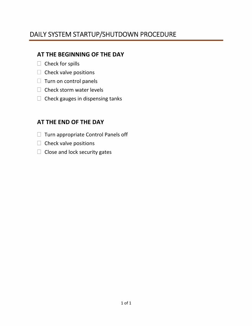
1 of 1
DAILY SYSTEM STARTUP/SHUTDOWN PROCEDURE
AT THE BEGINNING OF THE DAY
Check for spills
Check valve positions
Turn on control panels
Check storm water levels
Check gauges in dispensing tanks
AT THE END OF THE DAY
Turn appropriate Control Panels off
Check valve positions
Close and lock security gates
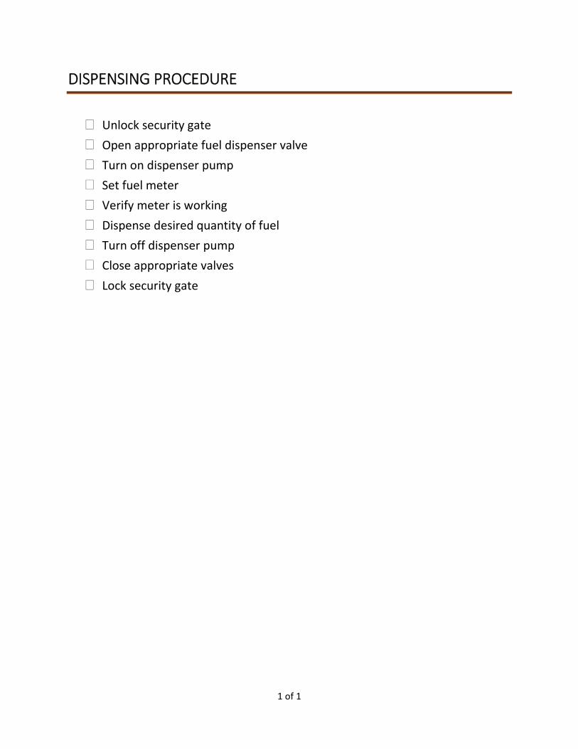
1 of 1
DISPENSING PROCEDURE
Unlock security gate
Open appropriate fuel dispenser valve
Turn on dispenser pump
Set fuel meter
Verify meter is working
Dispense desired quantity of fuel
Turn off dispenser pump
Close appropriate valves
Lock security gate
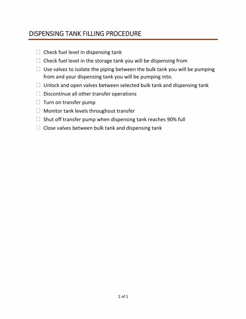
1 of 1
DISPENSING TANK FILLING PROCEDURE
Check fuel level in dispensing tank
Check fuel level in the storage tank you will be dispensing from
Use valves to isolate the piping between the bulk tank you will be pumping
from and your dispensing tank you will be pumping into.
Unlock and open valves between selected bulk tank and dispensing tank
Discontinue all other transfer operations
Turn on transfer pump
Monitor tank levels throughout transfer
Shut off transfer pump when dispensing tank reaches 90% full
Close valves between bulk tank and dispensing tank
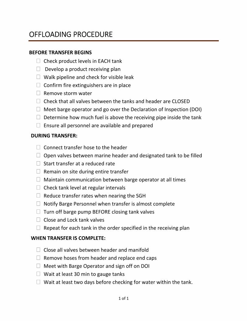
1 of 1
OFFLOADING PROCEDURE
BEFORE TRANSFER BEGINS
Check product levels in EACH tank
Develop a product receiving plan
Walk pipeline and check for visible leak
Confirm fire extinguishers are in place
Remove storm water
Check that all valves between the tanks and header are CLOSED
Meet barge operator and go over the Declaration of Inspection (DOI)
Determine how much fuel is above the receiving pipe inside the tank
Ensure all personnel are available and prepared
DURING TRANSFER:
Connect transfer hose to the header
Open valves between marine header and designated tank to be filled
Start transfer at a reduced rate
Remain on site during entire transfer
Maintain communication between barge operator at all times
Check tank level at regular intervals
Reduce transfer rates when nearing the SGH
Notify Barge Personnel when transfer is almost complete
Turn off barge pump BEFORE closing tank valves
Close and Lock tank valves
Repeat for each tank in the order specified in the receiving plan
WHEN TRANSFER IS COMPLETE:
Close all valves between header and manifold
Remove hoses from header and replace end caps
Meet with Barge Operator and sign off on DOI
Wait at least 30 min to gauge tanks
Wait at least two days before checking for water within the tank.
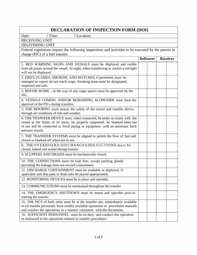
1 of 2
DECLARATION OF INSPECTION FORM (DOI) Date: Time: Location:RECEIVING UNIT DELIVERING UNIT Federal regulations require the following inspections and activities to be executed by the person in charge (PIC) of a fuel transfer.
Deliverer Receiver
1. RED WARNING SIGNS AND SIGNALS must be displayed and visible from all points around the vessel. At night, when transferring at anchor a red light will not be displayed.
2. FIRES, FLAMES, SMOKING AND MATCHES, if permitted, must be managed so vapors do not reach cargo. Smoking areas must be designated, inspected and safe.
3. REPAIR WORK – in the way of any cargo spaces must be approved by the PIC.
4. VESSELS COMING AND/OR REMAINING ALONGSIDE must have the approval of the PICs during transfers.
5. THE MOORING must ensure the safety of the vessel and transfer device through all conditions of tide and weather.
6. THE TRANSFER DEVICE must, when connected, be under no strain with thevessel at the limits of its moor, be properly supported, be blanked when not in use and be connected to fixed piping or equipment with an automatic back pressure nozzle.
7. THE TRANSFER SYSTEMS must be aligned to permit the flow of fuel and closed or blanked off when not in use.
8. THE OVERBOARD DI S C HA R G E S /SEA SUCTIONS mu s t be closed, lashed and sealed during transfer.
9. SCUPPERS AND DRAINS must be mechanically closed.
10. THE CONNECTIONS must be leak free, except packing glands providing the leakage does not exceed containment.
11. DISCHARGE CONTAINMENT must be available or deployed, if applicable and drip pans or drain tubs be placed appropriately.
12. MONITORING DEVICES must be in place and operable.
13. COMMUNICATIONS must be maintained throughout the transfer
14. THE EMERGENCY SHUTDOWN must be tested and operable prior to starting the transfer.
15. THE PICS of both units must be at the transfer site, immediately available to oil transfer personnel, have readily available operations or procedures manuals and conduct the operations in a manner consistent with the documents.
16. SUFFICIENT PERSONNEL must be on duty and conduct the operation as instructed in the operations manual or transfer procedures.
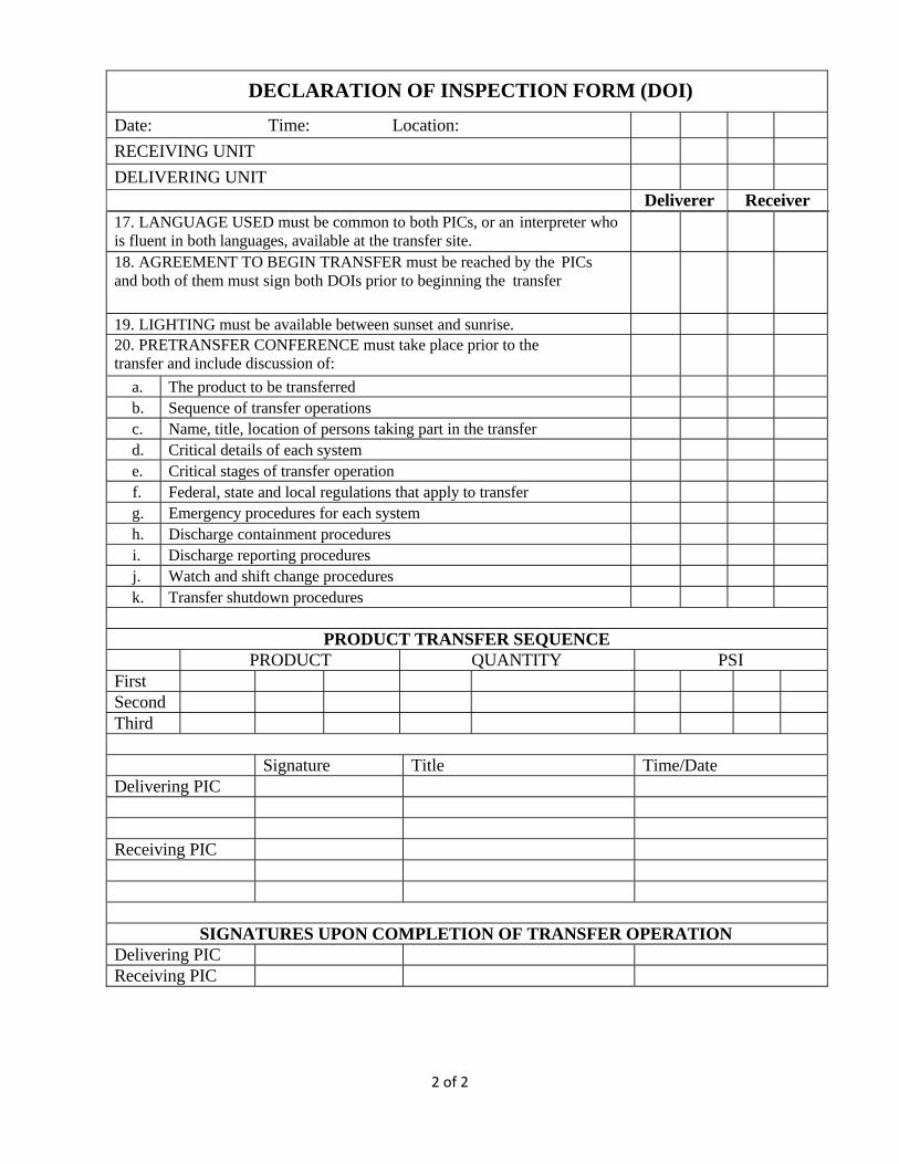
2 of 2
DECLARATION OF INSPECTION FORM (DOI)
Date: Time: Location: RECEIVING UNIT DELIVERING UNIT
Deliverer Receiver17. LANGUAGE USED must be common to both PICs, or an interpreter who is fluent in both languages, available at the transfer site.
18. AGREEMENT TO BEGIN TRANSFER must be reached by the PICs and both of them must sign both DOIs prior to beginning the transfer
19. LIGHTING must be available between sunset and sunrise.
20. PRETRANSFER CONFERENCE must take place prior to the transfer and include discussion of:
a. The product to be transferred
b. Sequence of transfer operations
c. Name, title, location of persons taking part in the transfer
d. Critical details of each system
e. Critical stages of transfer operation
f. Federal, state and local regulations that apply to transfer
g. Emergency procedures for each system
h. Discharge containment procedures
i. Discharge reporting procedures
j. Watch and shift change procedures
k. Transfer shutdown procedures
PRODUCT TRANSFER SEQUENCE PRODUCT QUANTITY PSIFirst
Second
Third
Signature Title Time/Date Delivering PIC
Receiving PIC
SIGNATURES UPON COMPLETION OF TRANSFER OPERATION Delivering PIC
Receiving PIC
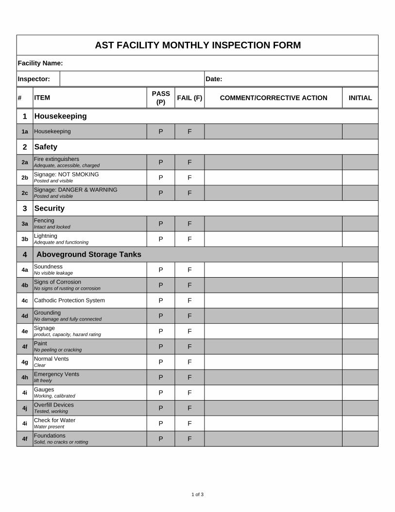
#PASS
(P)FAIL (F) COMMENT/CORRECTIVE ACTION INITIAL
1
1a P F
2
2a P F
2b P F
2c P F
3
3a P F
3b P F
4
4a P F
4b P F
4c P F
4d P F
4e P F
4f P F
4g P F
4h P F
4i P F
4j P F
4i P F
4f P F
AST FACILITY MONTHLY INSPECTION FORM
Housekeeping
Normal VentsClear
PaintNo peeling or cracking
FoundationsSolid, no cracks or rotting
Emergency Ventslift freely
GaugesWorking, calibrated
Overfill DevicesTested, working
Check for WaterWater present
SoundnessNo visible leakage
Signs of CorrosionNo signs of rusting or corrosion
Signageproduct, capacity, hazard rating
Cathodic Protection System
GroundingNo damage and fully connected
FencingIntact and locked
LightningAdequate and functioning
Aboveground Storage Tanks
Signage: NOT SMOKINGPosted and visible
Signage: DANGER & WARNINGPosted and visible
Security
Housekeeping
Safety
Fire extinguishersAdequate, accessible, charged
Facility Name:
Inspector: Date:
ITEM
1 of 3
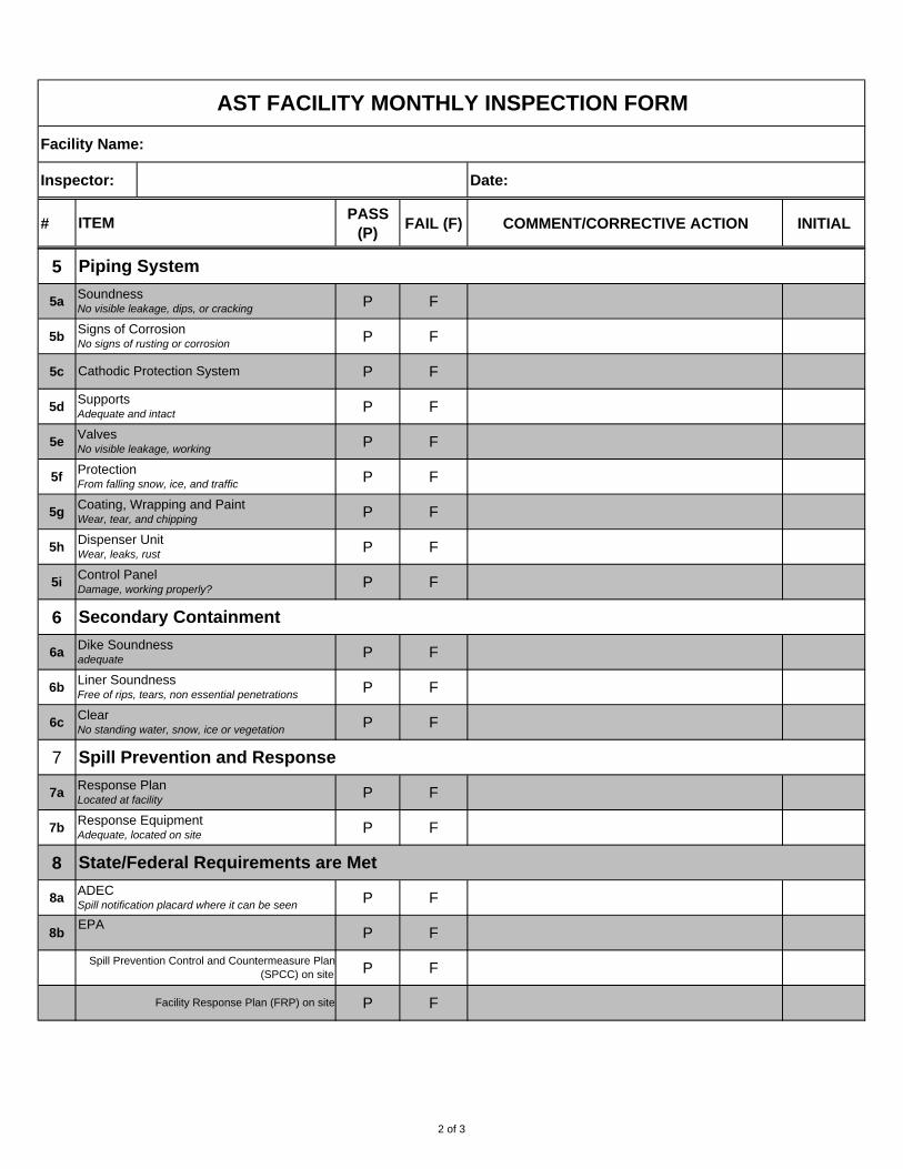
#PASS
(P)FAIL (F) COMMENT/CORRECTIVE ACTION INITIAL
AST FACILITY MONTHLY INSPECTION FORM
Facility Name:
Inspector: Date:
ITEM
5
5a P F
5b P F
5c P F
5d P F
5e P F
5f P F
5g P F
5h P F
5i P F
6
6a P F
6b P F
6c P F
7
7a P F
7b P F
8
8a P F
8b P F
P F
P F
ClearNo standing water, snow, ice or vegetation
Facility Response Plan (FRP) on site
Spill Prevention Control and Countermeasure Plan
(SPCC) on site
EPA
Response EquipmentAdequate, located on site
State/Federal Requirements are Met
ADECSpill notification placard where it can be seen
Spill Prevention and Response
Response PlanLocated at facility
Secondary Containment
Dike Soundnessadequate
Liner SoundnessFree of rips, tears, non essential penetrations
ValvesNo visible leakage, working
ProtectionFrom falling snow, ice, and traffic
Control PanelDamage, working properly?
Coating, Wrapping and PaintWear, tear, and chipping
Dispenser UnitWear, leaks, rust
Signs of CorrosionNo signs of rusting or corrosion
SupportsAdequate and intact
Cathodic Protection System
Piping System
SoundnessNo visible leakage, dips, or cracking
2 of 3
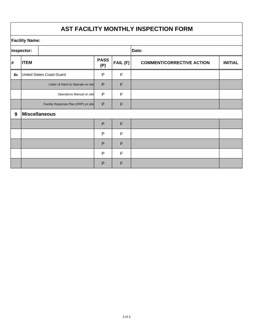
#PASS
(P)FAIL (F) COMMENT/CORRECTIVE ACTION INITIAL
AST FACILITY MONTHLY INSPECTION FORM
Facility Name:
Inspector: Date:
ITEM
8c P F
P F
P F
P F
9
P F
P F
P F
P F
P F
United States Coast Guard
Operations Manual on site
Facility Response Plan (FRP) on site
Letter of Intent to Operate on site
Miscellaneous
3 of 3
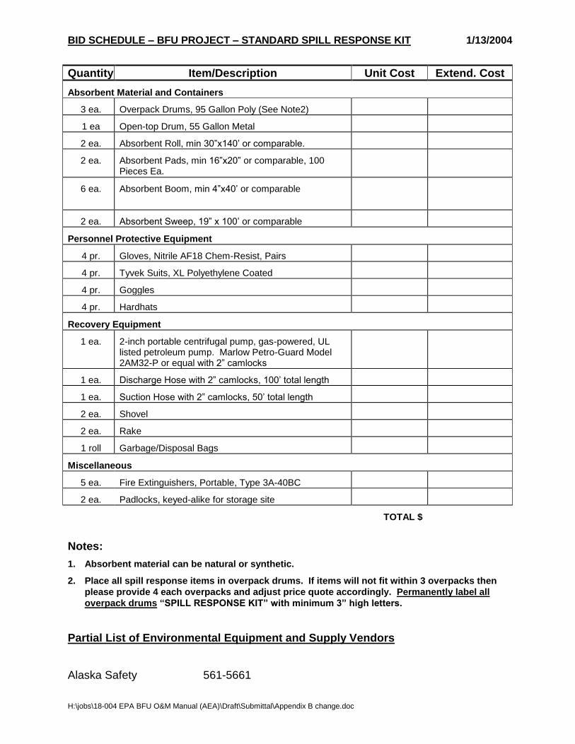
H:\jobs\18-004 EPA BFU O&M Manual (AEA)\Draft\Submittal\Appendix B change.doc
BID SCHEDULE – BFU PROJECT – STANDARD SPILL RESPONSE KIT 1/13/2004
Quantity Item/Description Unit Cost Extend. Cost
Absorbent Material and Containers
3 ea. Overpack Drums, 95 Gallon Poly (See Note2)
1 ea Open-top Drum, 55 Gallon Metal
2 ea. Absorbent Roll, min 30”x140’ or comparable.
2 ea. Absorbent Pads, min 16”x20” or comparable, 100 Pieces Ea.
6 ea. Absorbent Boom, min 4”x40’ or comparable
2 ea. Absorbent Sweep, 19” x 100’ or comparable
Personnel Protective Equipment
4 pr. Gloves, Nitrile AF18 Chem-Resist, Pairs
4 pr. Tyvek Suits, XL Polyethylene Coated
4 pr. Goggles
4 pr. Hardhats
Recovery Equipment
1 ea. 2-inch portable centrifugal pump, gas-powered, UL listed petroleum pump. Marlow Petro-Guard Model 2AM32-P or equal with 2” camlocks
1 ea. Discharge Hose with 2” camlocks, 100’ total length
1 ea. Suction Hose with 2” camlocks, 50’ total length
2 ea. Shovel
2 ea. Rake
1 roll Garbage/Disposal Bags
Miscellaneous
5 ea. Fire Extinguishers, Portable, Type 3A-40BC
2 ea. Padlocks, keyed-alike for storage site
TOTAL $
Notes:
1. Absorbent material can be natural or synthetic.
2. Place all spill response items in overpack drums. If items will not fit within 3 overpacks then
please provide 4 each overpacks and adjust price quote accordingly. Permanently label all
overpack drums “SPILL RESPONSE KIT” with minimum 3” high letters.
Partial List of Environmental Equipment and Supply Vendors
Alaska Safety 561-5661
H:\jobs\18-004 EPA BFU O&M Manual (AEA)\Draft\Submittal\Appendix B change.doc
Eagle Enterprises 562-2331 Inlet Petroleum Company 274-3835 Polar Supply 563-5000 Spill Shield International 561-6033 Unitech of Alaska 349-5142, 800-649-5859 Young’s Firehouse 344-5312, 800-478-5312 Northwest Pump & Equipment 522-9595, Fax 522-9696
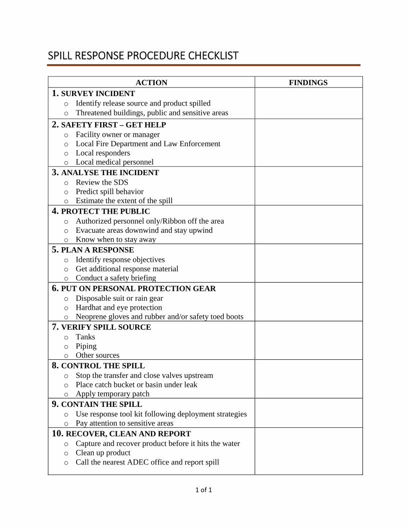
1 of 1
SPILL RESPONSE PROCEDURE CHECKLIST
ACTION FINDINGS 1. SURVEY INCIDENT
o Identify release source and product spilled o Threatened buildings, public and sensitive areas
2. SAFETY FIRST – GET HELP o Facility owner or manager o Local Fire Department and Law Enforcement o Local responders o Local medical personnel
3. ANALYSE THE INCIDENT o Review the SDS o Predict spill behavior o Estimate the extent of the spill
4. PROTECT THE PUBLIC o Authorized personnel only/Ribbon off the area o Evacuate areas downwind and stay upwind o Know when to stay away
5. PLAN A RESPONSE o Identify response objectives o Get additional response material o Conduct a safety briefing
6. PUT ON PERSONAL PROTECTION GEAR o Disposable suit or rain gear o Hardhat and eye protection o Neoprene gloves and rubber and/or safety toed boots
7. VERIFY SPILL SOURCE o Tanks o Piping o Other sources
8. CONTROL THE SPILL o Stop the transfer and close valves upstream o Place catch bucket or basin under leak o Apply temporary patch
9. CONTAIN THE SPILL o Use response tool kit following deployment strategies o Pay attention to sensitive areas
10. RECOVER, CLEAN AND REPORT o Capture and recover product before it hits the water o Clean up product o Call the nearest ADEC office and report spill

APPENDIX C – INVENTORY CALCULATIONS
DEPTH FACTOR CORRECTION TABLE
TEMPERATURE CORRECTION FACTOR TABLE
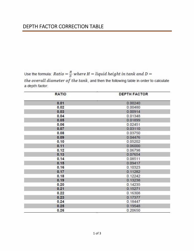
1 of 3
DEPTH FACTOR CORRECTION TABLE
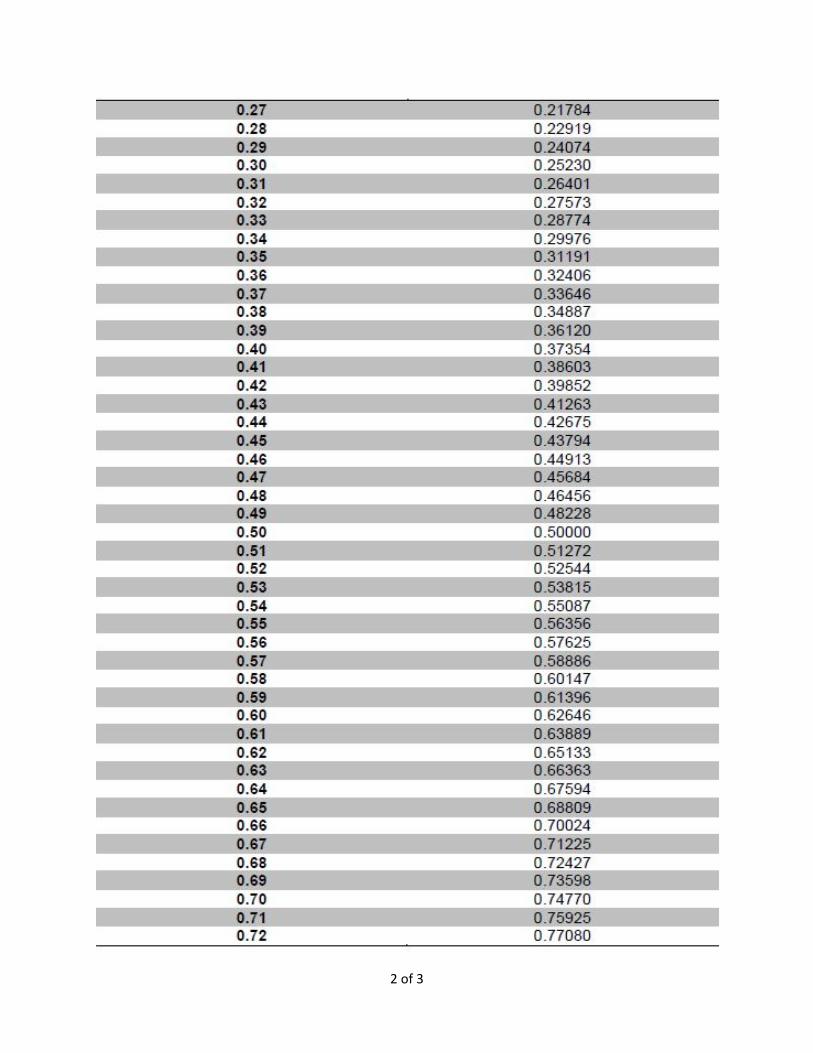
2 of 3
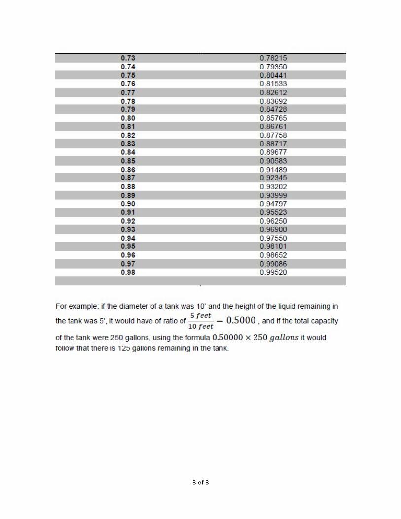
3 of 3
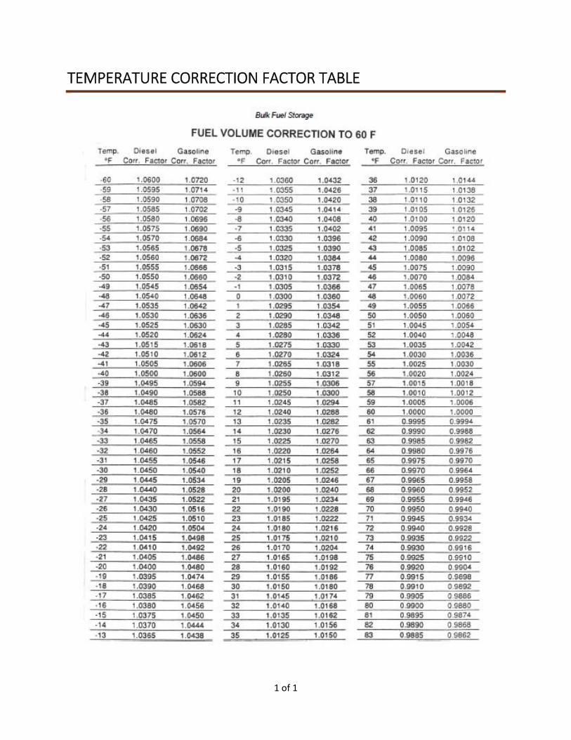
1 of 1
TEMPERATURE CORRECTION FACTOR TABLE