Embed Size (px)
Citation preview
RXB (KNX) applications library
CLC and RAD description of functions for CC-02
(CLC and RAD applications: see document CM110671).
Related documents
CM1Y9775 RXB integration, S-mode. CM1Y9776 RXB / RXL integration – Individual addressing. CM1Y9777 Third-party integration. CM1Y9779 Working with ETS.
CM110384en_04 21 Sep 2010 Siemens Building Technologies
2/140
Siemens RXB (KNX) Applications library CLC and RAD description of functions for CC-02 CM110384en_04 Building Technologies Contents 21 Sep 2010
Table of contents
1 Introduction .................................................................................................5 1.1 Revision history.............................................................................................5 1.2 Copyright .......................................................................................................5 1.3 Quality assurance .........................................................................................5 1.4 Document use / request to the reader...........................................................6 1.5 Target audience, prerequisites......................................................................6 1.6 Bus supply for RXB Konnex controllers ........................................................7 1.7 RXB Konnex controller communications.......................................................7 1.7.1 S-mode..........................................................................................................7 1.7.2 LTE mode......................................................................................................8 2 Definitions / Tools .......................................................................................9 2.1 Signals and parameters (presentation) .........................................................9 2.2 Supported tools ...........................................................................................11 2.3 Parameterization with ETS3 Professional ...................................................11 2.4 Parameterization using ACS .......................................................................12 2.5 Parameterization using the HandyTool .......................................................13 2.5.1 Operating HandyTool functions...................................................................14 2.5.2 Minor parameterization using room unit QAX34.3 ......................................14 2.5.3 Major parameterization using room unit QAX34.3 ......................................16 2.5.4 Select the device address using room unit QAX34.3..................................16 2.6 Upload/download parameters using room unit QAX34.3 ............................17 2.7 Test the periphery using room unit QAX34.3 ..............................................18 3 Select communications mode..................................................................20 3.1 Address zones in LTE mode (together with Synco) ...................................21 3.2 RXB application example with RMB795 for geographical and time switch
zones...........................................................................................................24 3.3 Implement application example...................................................................27 3.4 Heating and refrigeration demand zones ....................................................28 4 Applications / Parameters ........................................................................29 4.1 Select application ........................................................................................29 4.2 Parameter settings ......................................................................................30 5 Room operating modes ............................................................................31 5.1 Description ..................................................................................................31 5.2 Overview .....................................................................................................32 5.3 Determine the room operating mode with DESIGO (S-mode) ....................33 5.3.1 Local control of room operating mode via a window contact .....................34 5.3.2 Central control of room operating mode via input from the Use schedule ..35 5.3.3 Central and local control of room operating mode based on occupancy ....36 5.3.4 Central control of room operating mode via room operating mode schedule39 5.3.5 Local control of room operating mode with a room unit ..............................39 5.3.6 Local control of room operating mode via the Temporary Comfort mode
input ............................................................................................................40 5.3.7 Effective room operating mode ...................................................................41 5.3.8 DESIGO examples......................................................................................42 5.4 Determine the room operating mode with third-party products (S-mode) ...45 5.4.1 Local control of room operating mode via window contact input.................46 5.4.2 Central control of room operating mode with an input from the room
operating mode schedule............................................................................47 5.4.3 Central control of the room operating mode via the schedules Use and
Occupancy ..................................................................................................48 5.4.4 Central and local control of room operating mode based on occupancy ....48 5.4.5 Local control of room operating mode with a room unit ..............................50 5.4.6 Local control of room operating mode via the Temporary Comfort mode
input ............................................................................................................51 5.4.7 Effective room operating mode ...................................................................52

3/140
Siemens RXB (KNX) Applications library CLC and RAD description of functions for CC-02 CM110384en_04 Building Technologies Contents 21 Sep 2010
5.4.8 Third-party (S-mode) examples ..................................................................53 5.5 Determine the room operating mode with Synco (LTE mode)....................55 5.5.1 Local control of room operating mode via window contact input ................56 5.5.2 Central room operating mode control via Enable Comfort..........................56 5.5.3 Central control of room operating mode via room operating mode input... 57 5.5.4 Local control of room operating mode via presence detector .....................58 5.5.5 Local control of room operating mode with a room unit .............................. 59 5.5.6 LTE mode examples...................................................................................60 5.6 Determine the room operating mode without a bus (stand-alone)..............62 5.6.1 Local control of room operating mode via a window contact input ............63 5.6.2 Local control of room operating mode via presence detector .....................63 5.6.3 Local control of room operating mode with room unit ................................. 64 5.6.4 Example for stand-alone.............................................................................65 6 Setpoint calculation..................................................................................67 6.1 Description..................................................................................................67 6.1.1 Bus output for current setpoints ..................................................................68 6.1.2 Bus output effective setoints .......................................................................68 6.1.3 Bus outputs LTE mode ...............................................................................68 6.2 Setpoint settings with the tool .....................................................................69 6.3 Setpoint setting runtime ..............................................................................70 6.4 Central setpoint shift ...................................................................................71 6.5 Local setpoint shift ......................................................................................72 7 Temperature measurement......................................................................74 7.1 Room temperature measurement ...............................................................74 7.1.1 Local temperature sensor at PPS2 interface ..............................................74 7.1.2 Local temperature sensor at analog input ..................................................74 7.1.3 Averaging analog input & PPS2 interface...................................................75 7.1.4 Sensor correction........................................................................................75 7.1.5 Temperature sensor outputs on the Konnex bus........................................76 7.1.6 Temperature sensor input from Konnex bus...............................................77 7.2 Outside air temperature via Konnex bus (CLC02, RAD01) ........................78 8 Control sequences....................................................................................79 8.1 Radiator (RAD01) .......................................................................................79 8.1.1 Actuator type selection ...............................................................................79 8.1.2 Values representing radiator valve actuator positions ................................83 8.1.3 Valve exercising feature .............................................................................84 8.1.4 Override radiator valve actuators................................................................84 8.1.5 Downdraft compensation ............................................................................85 8.2 Chilled ceiling (CLC01) ...............................................................................87 8.2.1 Select actuator types for chilled ceiling.......................................................87 8.2.2 Values representing chilled ceiling valve actuator positions.......................88 8.2.3 Valve exercising feature .............................................................................90 8.2.4 Override chilled ceiling valve actuators.......................................................90 8.2.5 Dewpoint monitoring ...................................................................................90 8.2.6 Central/passive dewpoint monitoring..........................................................91 8.3 Chilled ceiling and radiator 4-pipe (CLC02)................................................92 8.3.1 Configuration and parameterization............................................................92 8.3.2 Override the valve actuator.........................................................................93 9 Master/slave ..............................................................................................94 9.1 S-mode .......................................................................................................95 9.1.1 Window switch (S-Mode) ............................................................................96 9.1.2 Presence detector (S-mode).......................................................................96 9.1.3 Dewpoint sensor (S-mode) .........................................................................96 9.2 LTE mode with zones .................................................................................97 9.2.1 Window switch (LTE mode) ........................................................................98 9.2.2 Presence detector (LTE mode)...................................................................98 9.2.3 Dewpoint sensor (LTE mode) .....................................................................98 9.3 Peripheral functions ....................................................................................99

4/140
Siemens RXB (KNX) Applications library CLC and RAD description of functions for CC-02 CM110384en_04 Building Technologies Contents 21 Sep 2010
10 General / central functions.....................................................................100 10.1 Send heartbeat and Receive timeout........................................................102 10.2 Digital inputs..............................................................................................102 10.3 Temporary Comfort mode .........................................................................103 10.4 Presence detector switch-on and switch-off delay ....................................103 10.5 Heating and cooling demand ....................................................................103 10.6 Heating/cooling signal output ....................................................................104 10.7 Special functions .......................................................................................105 10.8 Morning boost (Morning Warmup, 2) ........................................................106 10.9 Precooling (Precool, 5)..............................................................................106 10.10 Test mode (Test, 7) ...................................................................................107 10.11 Emergency heat (8)...................................................................................107 10.12 Free cooling (Freecool, 10) .......................................................................108 10.13 Alarm.........................................................................................................109 10.13.1 S-mode......................................................................................................109 10.13.2 LTE mode..................................................................................................110 10.14 Reset setpoint shift....................................................................................110 10.15 Free inputs/outputs ...................................................................................111 10.15.1 Digital inputs on the KNX bus ...................................................................111 10.15.2 KNX signals on digital/analog outputs.......................................................112 10.15.3 Mapping the sensor B1 to the Konnex bus ...............................................112 10.16 Software version .......................................................................................113 10.17 Device state ..............................................................................................113 11 Room unit ................................................................................................114 12 KNX information......................................................................................117 12.1 Reset and startup response ......................................................................117 12.2 LED flashing pattern..................................................................................117 12.3 Startup delay .............................................................................................118 12.4 Bus load ....................................................................................................118 12.5 S-mode communication objects for RAD/CLC ..........................................119 12.5.1 S-mode input communication objects .......................................................119 12.5.2 S-mode output communication objects .....................................................120 12.6 LTE-mode communication objects ............................................................121 12.7 HandyTool parameters by number............................................................122 12.8 HandyTool parameters, alphabetical ........................................................124 12.9 HandyTool enumerations ..........................................................................126 12.10 Data point type description........................................................................127 13 FAQ...........................................................................................................129 14 Integration of RXB in DESIGO/Synco....................................................132 14.1 Case 1: Integration in Synco .....................................................................132 14.2 Case 2: Integration in DESIGO .................................................................133 14.3 Case 3: Display in DESIGO, with shared Synco schedule .......................134 14.4 Case 4: Display in DESIGO/Synco, with shared Synco schedule ............135 14.5 Case 5: Display in DESIGO, separate schedules .....................................136 14.6 Case 6: Separate display, separate schedules.........................................137 14.7 Case 7: Separate display, shared Synco schedule...................................138 15 Working with different tools...................................................................139
5/140
Siemens RXB (KNX) Applications library CLC and RAD description of functions for CC-02 CM110384en_04 Building Technologies Introduction 21 Sep 2010
1 Introduction 1.1 Revision history
CM110384en_03 21.09.2010 10.2 interchanged HandyTool settings 2 and 3
Removed "fan coil"
CM110384en_03 28.02.2009 7.1.3 Temperature averaging 8.1.5 Downdraft compensation
CM110384en_02 14.03.2008 5.3.3, 5.4.4 Presence detector 8.1.1 Offset for motorized actuators (3rd party) 11.13.2 Alarm LTE: Alarm codes 12.9 Table "HandyTool enumerations"
CM110384en_01 30.11.2007 First edition
1.2 Copyright
This document may be duplicated and distributed only with the express permission of Siemens, and may be passed only to authorized persons or companies with the required technical knowledge.
1.3 Quality assurance
These documents have been prepared with great care. The contents of all documents are checked at regular intervals. Any corrections necessary are included in subsequent versions. Documents are automatically amended as a consequence of modifications and
corrections to the products described. Please ensure that you are aware of the latest revision date of the documentation. If you find any lack of clarity while using this document, or if you have any criticisms or suggestions, please contact the product manager in your nearest branch office, or write directly to the support team at Headquarters in Zug (see below). Support address: Siemens Switzerland Ltd. Building Technologies Group International Headquarters Field Support 5500 Gubelstrasse 22 6301 Zug, Switzerland Tel. +41 41 724 5500 Fax. +41 41 724 5501 E-mail: [email protected]
6/140
Siemens RXB (KNX) Applications library CLC and RAD description of functions for CC-02 CM110384en_04 Building Technologies Introduction 21 Sep 2010
1.4 Document use / request to the reader
Before using our products, it is important that you read the documents supplied with or ordered at the same time as the products (equipment, applications, tools etc.) carefully and in full. More information on the products and applications (e.g. system descriptions etc.) is available on the Internet/intranet at https://intranet10.sbt.siemens.com/business/building_comfort/systems/desigo/ra/. We assume that the users of these products and documents have the appropriate authorization and training, and that they are in possession of the technical knowledge necessary to use the products in accordance with their intended application. If, despite this, there is a lack of clarity or other problems associated with the use of the documentation, please do not hesitate to contact the Product Manager at your nearest branch office, or write directly to the support team at our Swiss headquarters. E-mail: [email protected]. Please note that without prejudice to your statutory rights, Siemens accepts no liability for any losses resulting from non-observance or improper observance of the points referred to above.
1.5 Target audience, prerequisites
This document assumes that users of the RXB Konnex controllers are familiar with the tools ETS3 Professional and/or Synco ACS and able to use them.
It also assumes that these users are aware of the specific conditions associated with EIB /KNX.
In most countries, specific EIB/KNX know-how is transmitted through training centers certified by the EIBA (see www.eiba.com or www.konnex.org).
For details concerning the Konnex bus see document CE1N3127.
For applications based on RXB together with Synco, refer also to the Synco documentation.
CE1N3121: RXB room controller management station. CE1P3127: Communications via Konnex bus.

7/140
Siemens RXB (KNX) Applications library CLC and RAD description of functions for CC-02 CM110384en_04 Building Technologies Introduction 21 Sep 2010
1.6 Bus supply for RXB Konnex controllers
RXB controllers work without bus supply if the following conditions are adhered to:
Parameterize only using the Handy Tool (not with ETS3 or ACS). No integration in a building automation and control system (e.g. DESIGO, Synco). No changeover operation (sensor signal via bus). No outdoor temperature via bus. No master/slave combinations. Else, the Konnex bus, used by RXB room controllers for communications, requires a bus supply. Each controller consumes 5 mA. Thus, select the supply according to the number of controllers. We recommend the following products:
Manufacturer Type Designation
Siemens Building Technologies ACX95.320/ALG Power supply 320 mA
Siemens Automation and Drives 5WG1 125-1AB01 Power supply 160 mA
5WG1 125-1AB11 Power supply 320 mA
5WG1 125-1AB21 Power supply 640 mA
1.7 RXB Konnex controller communications
The RXB Konnex controllers support communications as defined in the Konnex specification.
This specification defines the following modes among others:
S-Mode = System mode. LTE mode= Logical Tag Extended Mode
This is a new mode which supports simpler engineering and is used with Synco.
1.7.1 S-Mode
This mode corresponds to EIB communications. Connections are established via ETS3 Professional and group addresses.
This ensures a link to the existing EIB environment. Refer to the EIB manual for more information on this mode.

8/140
Siemens RXB (KNX) Applications library CLC and RAD description of functions for CC-02 CM110384en_04 Building Technologies Introduction 21 Sep 2010
1.7.2 LTE mode
LTE mode was specifically designed to simplify engineering. Unlike with S-mode, there is no need to create the individual connections (group addresses) in the tool. The devices establish the connections themselves. To make this possible, the following was defined:
Every device or sub-device is located within a zone. Every data point (input or output) is assigned to a zone. Every data point (input or output) has a precisely defined name. Whenever an output and an input with the same name are located in the same zone, a connection is established automatically as shown in the following diagram.
Controller
Valve
Sensor
Time switch zone 1. 1. 1
Outside temperature zone 3
Geogr. zone 2.5.1Geogr. zone 2.5.1
Heat distr zone 1
Cooling coil
Outside temperature1
0385
Z0
1en
Outside temperature
Cooling coil
Outside temperature zone 3
The following types of zone are defined:
Geographical zones. (Syntax: Apartment . Room . Subzone). The time-switch zone is a geographical zone used for special purposes.
Outside temperature zones. Heat distribution zones. Refrigeration distribution zones. For further details, refer to the Konnex specification.
Definitions
Types of zone

9/140
Siemens RXB (KNX) Applications library CLC and RAD description of functions for CC-02 CM110384en_04 Building Technologies Definitions / Tools 21 Sep 2010
2 Definitions / Tools 2.1 Signals and parameters (presentation)
Inputs, outputs and parameters of an application can be influenced in various ways. This description of functions applies the following symbols:
The room unit influences parameters shown with this symbol.
Parameters identified in this way are parameterized using ETS3 Professional (EIB tool software).
The RXB Konnex controllers CANNOT be parameterized with ETS2.
Parameters identified with this symbol are parameterized with the ACS service tool.
Parameters identified with this symbol are parameterized with the HandyTool. This indicates inputs and outputs which communicate with other KNX devices. They are communication objects (CO). Graphical symbol for an S-mode input communication object. Graphical symbol for an LTE input communication object. Graphical symbol for an S-mode output communication object. Graphical symbol for an LTE output communication object. The communication objects of the RXB Konnex controllers work in part in S-mode, in part in LTE mode, and in part in both modes. These objects are described accordingly. The following table describes each communication object working in S-mode:
Schedule Use (input communication object)
Flags R W C T U
Type Receive timeout States
0 1 1 0 0 20.002
DPT_BuildingMode Yes 0 = In use
1 = Not in use 2 = Protection
(1) Communication object name.
Flags: R Read W Write C Communication T Transmit U Update
Type Konnex data type.
Send heartbeat Yes = Cyclical send.
Receive timeout Yes = Cyclical receive (timeout).
States or values Range of states or values which can be adopted by the communication object.
A list of all S-mode communication objects is located in section 12.5; see a detailed description of the Konnex data types in section 12.10.
Room unit
ETS3 Professional
STOP Important!
ACS Service
HandyTool
KNXR
CO
S-mode communication objects (1)
Key
Note

10/140
Siemens RXB (KNX) Applications library CLC and RAD description of functions for CC-02 CM110384en_04 Building Technologies Definitions / Tools 21 Sep 2010
All communication objects operating in LTE mode are described as follows:
Possible partner function blocks 3)
Known partner devices 4)
HVACMode 1)
TimeswitchZone 2)
110 HVACS HVAC-Mode Scheduler
104 PMC Program to HVAC-Mode Conversion
Siemens: Synco RM700
Key
1) The name of the LTE communication object is entered here.
2) Each LTE communication object is assigned to a zone. This is recorded here.
3) This is where suitable partner function blocks are listed. They are described in the Konnex specification.
4) The devices listed here (manufacturer and type) are suitable partners for the communication object.
For a list of all the LTE-mode communication objects used, refer to section 12.6. For details of the Konnex data types refer to Section 12.7. The left margin contains the symbol for the HandyTool next to a table containing the parameter number, short name and default value. The number has syntax *xxx, with xxx being a three-digit number.
HandyTool Parameters Short name Basic setting
*069 Comfort heating setpoint 25.0 °C
A list of the parameters by number and in alphabetical order is located in chapters 12.7 and 12.8, and in the description of the functions. A table of parameters with enumerations fort he HandyTool is shown in Section 12.9.
LTE-mode communication objects
Note
HandyTool
Note

11/140
Siemens RXB (KNX) Applications library CLC and RAD description of functions for CC-02 CM110384en_04 Building Technologies Definitions / Tools 21 Sep 2010
2.2 Supported tools
The RXB Konnex controllers can be commissioned either with the Konnex tool ETS3 Professional, the Synco ACS Service too or the HandyTool.
Be careful when using different tools. The following rule applies: Last one's right!
When you use an OCI700 as the interface, connect it to the controller's or room unit's service socket. The OCI700 must be powered via USB by the computer as long as it is connected to the service socket. Otherwise, the LCD display for the room device goes dark and the controller goes to addressing mode.
2.3 Parameterization with ETS3 Professional
This manual does not describe how physical addresses are defined. Refer to the EIB manual for more details. Open the project and select a device. To start parameterization, select Edit, Edit parameters.
STOP Important!
ETS3 Professional
12/140
Siemens RXB (KNX) Applications library CLC and RAD description of functions for CC-02 CM110384en_04 Building Technologies Definitions / Tools 21 Sep 2010
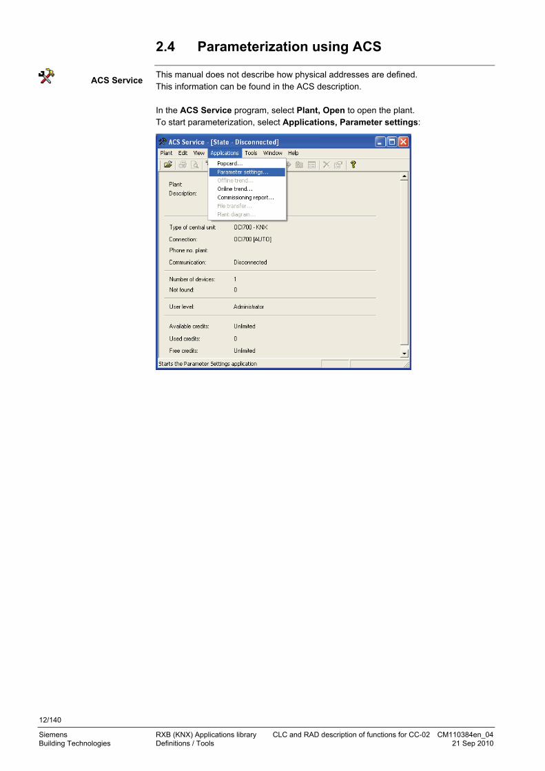
2.4 Parameterization using ACS
This manual does not describe how physical addresses are defined. This information can be found in the ACS description. In the ACS Service program, select Plant, Open to open the plant. To start parameterization, select Applications, Parameter settings:
ACS Service
13/140
Siemens RXB (KNX) Applications library CLC and RAD description of functions for CC-02 CM110384en_04 Building Technologies Definitions / Tools 21 Sep 2010
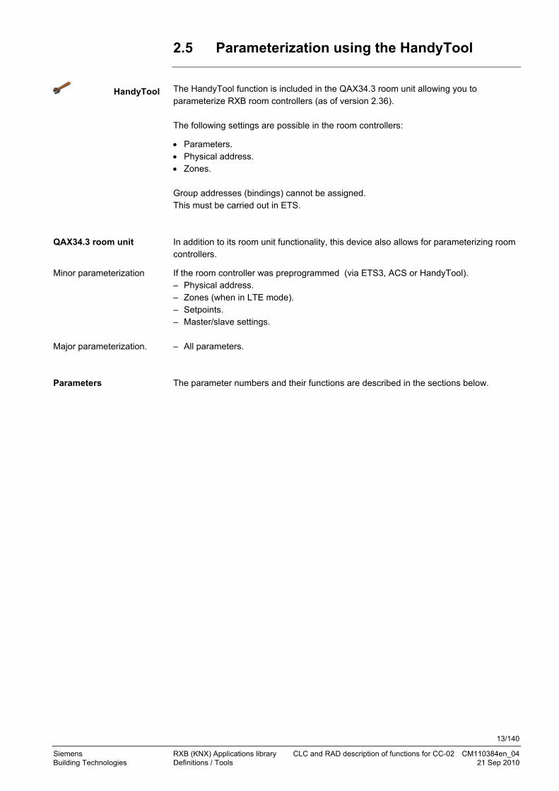
2.5 Parameterization using the HandyTool
The HandyTool function is included in the QAX34.3 room unit allowing you to parameterize RXB room controllers (as of version 2.36). The following settings are possible in the room controllers:
Parameters. Physical address. Zones. Group addresses (bindings) cannot be assigned. This must be carried out in ETS. In addition to its room unit functionality, this device also allows for parameterizing room controllers.
If the room controller was preprogrammed (via ETS3, ACS or HandyTool). – Physical address. – Zones (when in LTE mode). – Setpoints. – Master/slave settings. – All parameters. The parameter numbers and their functions are described in the sections below.
HandyTool
QAX34.3 room unit
Minor parameterization
Major parameterization.
Parameters
14/140
Siemens RXB (KNX) Applications library CLC and RAD description of functions for CC-02 CM110384en_04 Building Technologies Definitions / Tools 21 Sep 2010
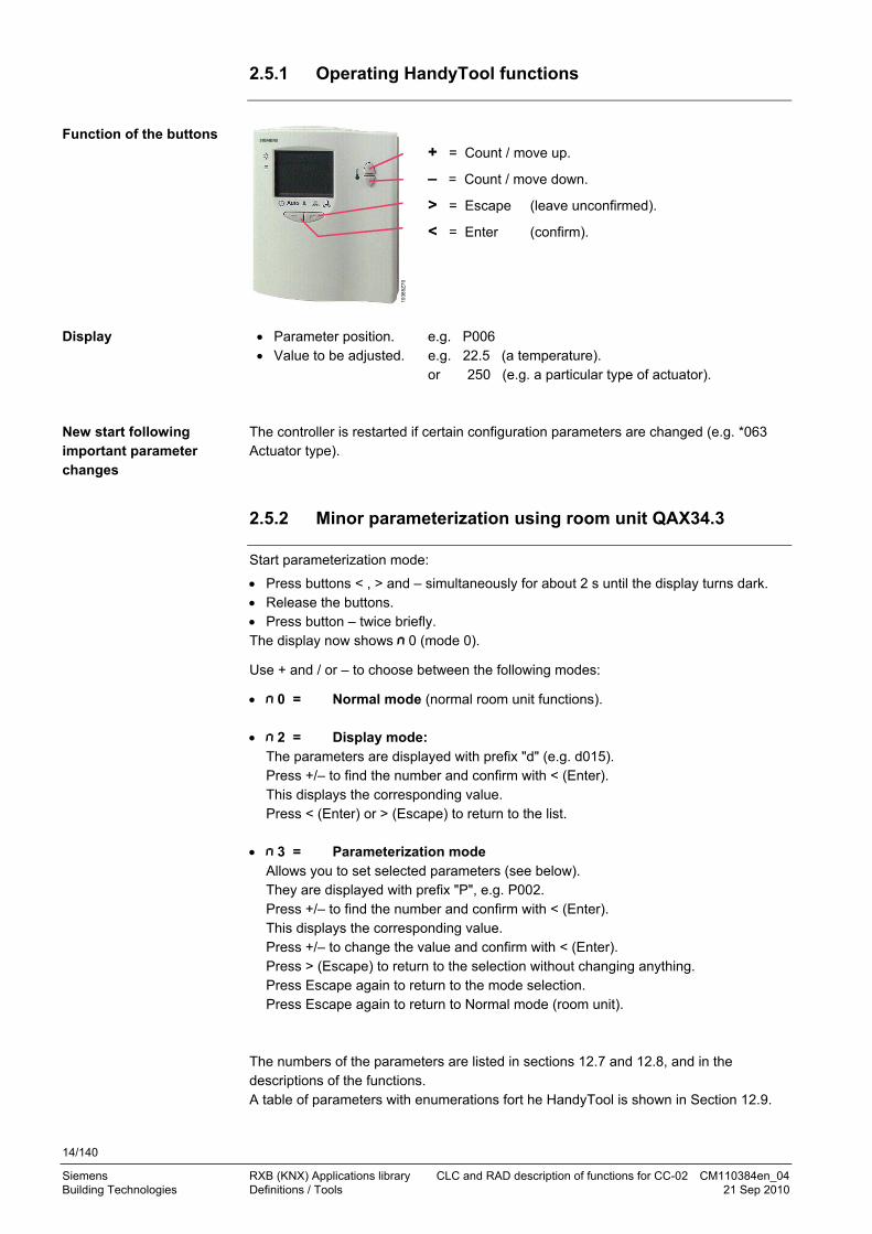
2.5.1 Operating HandyTool functions
Function of the buttons
1038
5Z7
0
+ = Count / move up.
– = Count / move down.
> = Escape (leave unconfirmed).
< = Enter (confirm).
Display Parameter position. e.g. P006 Value to be adjusted. e.g. 22.5 (a temperature).
or 250 (e.g. a particular type of actuator). The controller is restarted if certain configuration parameters are changed (e.g. *063 Actuator type).
2.5.2 Minor parameterization using room unit QAX34.3
Start parameterization mode:
Press buttons < , > and – simultaneously for about 2 s until the display turns dark. Release the buttons. Press button – twice briefly. The display now shows 0 (mode 0).
Use + and / or – to choose between the following modes:
0 = Normal mode (normal room unit functions).
2 = Display mode: The parameters are displayed with prefix "d" (e.g. d015). Press +/– to find the number and confirm with < (Enter). This displays the corresponding value. Press < (Enter) or > (Escape) to return to the list.
3 = Parameterization mode Allows you to set selected parameters (see below). They are displayed with prefix "P", e.g. P002. Press +/– to find the number and confirm with < (Enter). This displays the corresponding value. Press +/– to change the value and confirm with < (Enter). Press > (Escape) to return to the selection without changing anything. Press Escape again to return to the mode selection. Press Escape again to return to Normal mode (room unit).
The numbers of the parameters are listed in sections 12.7 and 12.8, and in the descriptions of the functions. A table of parameters with enumerations fort he HandyTool is shown in Section 12.9.
New start following important parameter changes
15/140
Siemens RXB (KNX) Applications library CLC and RAD description of functions for CC-02 CM110384en_04 Building Technologies Definitions / Tools 21 Sep 2010
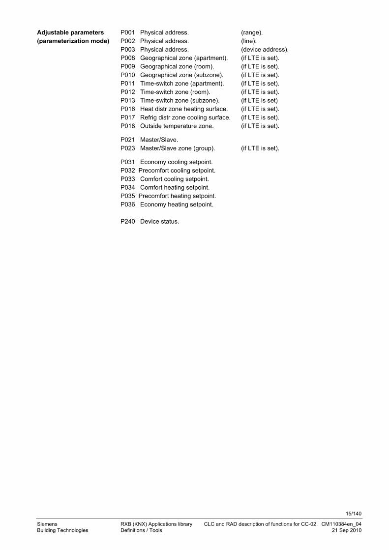
P001 Physical address. (range). P002 Physical address. (line). P003 Physical address. (device address). P008 Geographical zone (apartment). (if LTE is set). P009 Geographical zone (room). (if LTE is set). P010 Geographical zone (subzone). (if LTE is set). P011 Time-switch zone (apartment). (if LTE is set). P012 Time-switch zone (room). (if LTE is set). P013 Time-switch zone (subzone). (if LTE is set) P016 Heat distr zone heating surface. (if LTE is set). P017 Refrig distr zone cooling surface. (if LTE is set). P018 Outside temperature zone. (if LTE is set).
P021 Master/Slave. P023 Master/Slave zone (group). (if LTE is set).
P031 Economy cooling setpoint. P032 Precomfort cooling setpoint. P033 Comfort cooling setpoint. P034 Comfort heating setpoint. P035 Precomfort heating setpoint. P036 Economy heating setpoint. P240 Device status.
Adjustable parameters (parameterization mode)

16/140
Siemens RXB (KNX) Applications library CLC and RAD description of functions for CC-02 CM110384en_04 Building Technologies Definitions / Tools 21 Sep 2010
2.5.3 Major parameterization using room unit QAX34.3
This parameterization mode allows for changing also critical values. As a worst case scenario, components (controllers/actuators or other plant parts) may be destroyed. Start parameterization mode:
Press buttons < , > and – simultaneously for about 2 s until the display turns dark. Release the buttons. Press button – twice briefly. Press buttons + and – simultaneously for approx. 2s The display goes dark. Press button + twice briefly. The display now shows 0 (mode 0).
Use + and / or – to choose between the following modes:
0 = Normal mode (normal room unit functions). 1 = Test mode (see 2.7). 2 = Display mode (see 2.5.2). 3 = Parameterization mode (see 2.5.2). 4 = Upload (see 2.6). 5 = Download (see 2.6). 6 = Service mode:
All parameters can be set. They are displayed with prefix "S", e.g. S053. Press +/– to find the number and confirm with < (Enter). This displays the corresponding value. Press +/– to change the value and confirm with < (Enter). Press > (Escape) to return to the selection without changing anything. Press Escape again to return to the mode selection. Press Escape again to return to Normal mode (room unit).
A list of the parameters by number and in alphabetical order is located in chapters 12.7 and 12.8, and in the description of the functions. A table of parameters with enumerations fort he HandyTool is shown in Section 12.9.
2.5.4 Select the device address using room unit QAX34.3
The device address is contained in parameters *001, *002 und *003. *001 can assume the values 0 … 15. *002 can assume the values 0 … 15. *003 can assume the values 1 … 255. Example: 0.2.27 Each address must be unique within a plant.
STOP Caution
Note

17/140
Siemens RXB (KNX) Applications library CLC and RAD description of functions for CC-02 CM110384en_04 Building Technologies Definitions / Tools 21 Sep 2010
2.6 Upload/download parameters using room unit QAX34.3
This function requires a QAX34.3 with index D or higher!
The HandyTool can save 5 different controller parameter sets. These are uploaded from a fully parameterized controller using the Upload function. Download allows for transferring such a data set to one or several controllers (prerequisite: same controller type). The address, and for LTE the zones, must be adjusted (see 2.5.2). Download allows for changing also critical values. As a worst case scenario, components (controllers/actuators or other plant parts) may be destroyed. Start parameterization mode:
Press buttons < , > and – simultaneously for about 2 s until the display turns dark. Release the buttons. Press button – twice briefly. Press buttons + and – simultaneously for approx. 2s The display goes dark. Press button + twice briefly. The display now shows 0 (mode 0).
Use + and / or – to choose between the following modes:
0 = Normal mode (normal room unit functions). 1 = Test mode (see 2.7). 2 = Display mode (see 2.5.2). 3 = Parameterization mode (see 2.5.2). 4 = Upload. 5 = Download. 6 = Service mode. If 4 or 5 is displayed, this mode can be selected via < (Enter). The storage number (c1) is displayed and can be changed via + / – . Select the desired storage (1 .. 5) via < (Enter). If storage is empty, upload begins and the display flashes.
OK is displayed after successful upload. If the storage is full, "dEL" for "Delete?" is displayed.
Pressing <(Enter) at this time overwrites the existing set. If you press > (Escape), the storage number which you can change via + / – is displayed.
If the parameter set does not match the connected controller, error message "Err" is
displayed. Press > (Escape) to return to the storage number and select a different number.
If the parameter set matches the connected controller, start download (display flashes).
If connected successfully, "P1" is displayed (see 2.5.2).
STOP Caution
Upload
Download

18/140
Siemens RXB (KNX) Applications library CLC and RAD description of functions for CC-02 CM110384en_04 Building Technologies Definitions / Tools 21 Sep 2010
2.7 Test the periphery using room unit QAX34.3
This function requires a QAX34.3 with index D or higher!
The HandyTool allows you to test the connected field devices (sensors, actuators). This works only for the controller connected to the HandyTool; master/slave operation is not possible. An application must be selected and fully parameterized in the controller (address and zones can contain default values). Start parameterization mode:
Press buttons < , > and – simultaneously for about 2 s until the display turns dark. Release the buttons. Press button – twice briefly. Press buttons + and – simultaneously for approx. 2 s The display goes dark. Press button + twice briefly. The display now shows 0 (mode 0).
Use + and / or – to choose between the following modes:
0 = Normal mode (normal room unit functions). 1 = Test mode 2 = Display mode (see 2.5.2). 3 = Parameterization mode (see 2.5.2). 4 = Upload (see 2.6). 5 = Download (see 2.6). 6 = Service mode. The following positions can be selected depending on the type of parameterization. They are displayed with prefix "T". The list shows all theoretically possible positions. However, only positions that are available for selection based on the type of parameterization are displayed.
Theoretically possible positions for periphery testing:
T 01 Sensor input B1 9) Value of B1 in °C.
T 11 Digital input D1 9) True state of the contact at D1 (0 = open; 1 = closed).
T 12 Digital input D2 9) True state of the contact at D2 (0 = open; 1 = closed).
T 21 Heating valve 1) 2) 7) By considering the configuration (proportional; 100 = 100% pos. signal).
T 22 Cooling valve 1) 2) 7) By considering the configuration (proportional; 100 = 100% pos. signal).
T 25 Heating surface 1) 4) 7) By considering the configuration (proportional; 100 = 100% pos. signal).
T 51 Triac Y1 6) (0 = Triac disabled; 1 = enabled).
T 52 Triac Y2 6) (0 = Triac disabled; 1 = enabled).
T 53 Triac Y3 6) (0 = Triac disabled; 1 = enabled).
T 54 Triac Y4 6) (0 = Triac disabled; 1 = enabled).
1) Considering the configuration means:
– For thermal actuators, the output is clocked 1:1 during the first 400 s, then as per the % entry.
– Motorized actuators open at 100% 1.5 times the runtime, and close at 0% 1.5 times the runtime.
Prerequisite

19/140
Siemens RXB (KNX) Applications library CLC and RAD description of functions for CC-02 CM110384en_04 Building Technologies Definitions / Tools 21 Sep 2010
2) T21 and T22 have the same effect in changeover applications. 4) Only for RXB24.1/CC-02. 6) If not used by the application. 7) Operates only the I/Os of the controller in test mode, no bus actuators. 9) Values are correct when read, but will not automatically be updated.
The positions can be selected with < (Enter).
The inputs are displayed Outputs can be set via < (Enter) and + / –. To exit test mode, press >- (Escape) 2 - 3 times (depending on the situation). If no further button is pressed for 5 minutes, the controller automatically reassumes Normal mode and all physical outputs are switched back.
Monitor and operate
Exit test mode

20/140
Siemens RXB (KNX) Applications library CLC and RAD description of functions for CC-02 CM110384en_04 Building Technologies Select communications mode 21 Sep 2010
3 Select communications mode
Section 1 shows that RXB room controllers can work in both S- and LTE mode. They are used in S-mode when networked with the DESIGO automation and control system, and in LTE mode with Synco. The factory setting of all controllers and the basic setting of the tools is 0 = S-Mode. This minimizes the bus load. Exception: ACS Service changes the setting immediately to 1 = LTE + S. The ETS3 Professional is used in DESIGO networks. It can be used for operation in
– S-mode. – LTE-mode and S-mode.
The send heartbeat and receive timeout are described in section 10.1.
Note
ETS3 Professional

21/140
Siemens RXB (KNX) Applications library CLC and RAD description of functions for CC-02 CM110384en_04 Building Technologies Select communications mode 21 Sep 2010
The ACS service tool is used in Synco networks. It has access to LTE mode only.
HandyTool Setting Mode
*006 Communication mode 0 S-mode
1 LTE and S-mode
3.1 Address zones in LTE mode (together with Synco)
This section applies only to LTE mode.
Zone addresses must be allocated in cases where RXB Konnex controllers are used in LTE mode (e.g. together with Synco). These must be defined together with the Synco devices at the planning stage.
The zones to be defined are:
Geographical zone (Apartment . Room . Subzone) Apartment = ---, 1...126 Room = ---, 0...63 Subzone = ---, 0...15
Zone in which an RXB Konnex controller is located. Other room-specific devices may also be located in this zone.
The designations "Apartment, Room and Subzone do not need to be taken literally. For example, Apartment can be used to refer to a group of rooms, floor, or section of a building. Room, however, really does refer to a room.. Subzone is unlikely to be used much for HVAC devices – it is more relevant to other disciplines such as lighting (keep the setting 1).
Time switch zone
(Apartment . Room . Subzone) Apartment = ---, 1...126 Room = ---, 0...63 Subzone = ---, 0...15
This zone has the same structure as the geographical zone. It indicates the source of the schedule for the RXB Konnex controllers. The same zone must also contain a device to provide the schedule (e.g. a Synco RMx7xx or RMB795).
In a Synco network, Room and Subzone must always be set to 1.
Refrig distr zone cooling surface
Zone = ---, 1...31
Chilled water-specific information of a chilled ceiling is exchanged within this zone (e.g. cooling demand). This zone also includes a Synco device to process the information (e.g. RMU7xx or RMB7xx).
Heat distr zone heating surface
Zone = ---, 1...31
Hot water-specific information of a radiator is exchanged within this zone (e.g. heating demand). This zone also includes a Synco device to process the information (e.g. RMU7xx or RMB7xx).
ACS Service

22/140
Siemens RXB (KNX) Applications library CLC and RAD description of functions for CC-02 CM110384en_04 Building Technologies Select communications mode 21 Sep 2010
Outside temperature zone
Zone = ---, 1...31
The outside temperature is exchanged in this zone (all Synco 700 devices).
Master/slave zone
(Apartment . Room . Subzone) Apartment = ---, 1...126 Room = ---, 0...63 Subzone = ---, 0...15
In cases where RXB controllers are to be operated in master/slave mode, a master/slave zone must also be defined. For the master, it is usual to enter the geographical zone of the master. The same master/slave zone is used for the slave as for the master.
See also "Master/slave", page 94.
Select the menu option Communication.
ETS3 Professional

23/140
Siemens RXB (KNX) Applications library CLC and RAD description of functions for CC-02 CM110384en_04 Building Technologies Select communications mode 21 Sep 2010
The zones are defined under Communication.
Individual zones can also be disabled via command if they are not being used. This has the advantage of reducing the load on the bus.
HandyTool See the parameter in the last column of the following table.
Short name Basic setting Parameter
Geogr zone (ap) –1 (out of service) *008
Geogr zone (room) 1 *009
Geogr zone (subz) 1 *010
T'swi zone (apartm) 1 *011
TS zone (room) 1 *012
TS zone (subzone) 1 *013
Heat distr zone –1 (out of service) *016
Refrig distr zone –1 (out of service) *017
Outside temp zone 1 *018
Value 0 means broadcast and is thus not allowed. If the geogr zone or a TS zone has value = -1 for one of the three values, the entire
zone is out of service.
ACS Professional
Reduce bus load
Notes

24/140
Siemens RXB (KNX) Applications library CLC and RAD description of functions for CC-02 CM110384en_04 Building Technologies Select communications mode 21 Sep 2010
3.2 RXB application example with RMB795 for geographical and time switch zones
The room group philosophy is applied to the following example. This example uses FNC applications. CLC and RAD applications, however, apply the same principle.
The building has three stories used by different companies for their headquarters. The following companies rent offices on the third floor:
– Company Sport AG with conference room and two offices. – Company Logistics GmbH with 6 offices and 1 meeting room.
Each of the two companies wants to operate their room groups at different operating modes, i.e. with the following separate items: – Schedules. – Setpoints. – Fire and smoke extraction functions.
The following example shows the rooms on the third floor for the two companies Logistiics Ltd and Sport Ltd:
D: 101G: 4.1.1
D: 102G: 4.2.1
D: 103G: 3.1.1
D: 104G: 3.2.1
D: 105G: 3.3.1
D: 106G: 3.4.1
D: 107G: 3.5.1
D: 108G: 3.6.1
D: 109G: 3.7.1
D: 110G: 2.1.1
D: 111G: 2.2.1
D: 112G: 2.3.1
D: 113G: 2.4.1
D: 114G: 1.1.1
RMB795
301 302 303
304
305
306307
308
309
Logistics Ltd
Sport Ltd
103
85Z
03e
n
Office
Conferenceroom
Conference room Reception Office
OfficeOffice
Office
Office
D = Device address, G = Geographical zone (Apartment . Room . Subzone).
Building floor plan
User requirements / operating modes
Floor plan, third floor
Key
25/140
Siemens RXB (KNX) Applications library CLC and RAD description of functions for CC-02 CM110384en_04 Building Technologies Select communications mode 21 Sep 2010
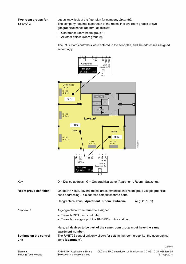
Let us know look at the floor plan for company Sport AG. The company required separation of the rooms into two room groups or two geographical zones (apartm) as follows:
– Conference room (room group 1). – All other offices (room group 2). The RXB room controllers were entered in the floor plan, and the addresses assigned accordingly:
D: 110G: 2.1.1
D: 111G: 2.2.1
D: 112G: 2.3.1
D: 113G: 2.4.1
D: 114G: 1.1.1
RMB795309
308
307
x x x x x
Q Q
x x x
1 2
Raumgruppe 2
x x x x x
Q Q
x x x
1 2
Room group 1
SA EA
RelaySetpoint prio
EnableConference
Sport Ltd
103
85Z
04e
n
Room group 2 RelaySetpoint prio
SA EAEnableOffice
Office
Conferenceroom
Office
D = Device address, G = Geographical zone (Apartment . Room . Subzone).
On the KNX bus, several rooms are summarized in a room group via geographical zone addressing. This address comprises three parts:
Geographical zone: Apartment . Room . Subzone (e.g. 2 . 1 . 1)
A geographical zone must be assigned:
– To each RXB room controller. – To each room group of the RMB795 control station. Here, all devices to be part of the same room group must have the same apartment number. The RMB795 control unit only allows for setting the room group, i.e. the geographical zone (apartment).
Two room groups for Sport AG
Key
Room group definition
Important!
Settings on the control unit

26/140
Siemens RXB (KNX) Applications library CLC and RAD description of functions for CC-02 CM110384en_04 Building Technologies Select communications mode 21 Sep 2010
The room and subzone are fixed (room = 1, subzone = 1).
To set the room group at the control unit, the following applies: Room group = Geographical zone (apartment . 1 . 1).
The following settings are available in the RXB room controllers:
– Geographical zone (apartment). – Geographical zone (room). – Geographical zone (subzone). For HVAC applications with RXB room controllers, use only the geographical zone (apartment) and the geographical zone (room).
Extending the address by the geographical zone (room) results in room control by means of RXB room controllers. This in turn allows for individual operating interventions (from an operator unit and the control unit via the bus) such as room setpoint correction in any room or on any device.
For additional division of the geographical zone (room), the RXB room controller offers the geographical zone (subzone). This subzone can be meaningful in lighting installations, e.g. if a geographical zone (room) must be subdivided into two subzones "lighting along window" and "lighting along hallway". For HVAC applications, keep the subzone at = 1.
The supplementary labels "apartment", "room" and "subzone" are predefined by Konnex. However, apartment does necessarily denote an actual apartment. Each KNX member requires an individual device address, entered in the floor plan above with D:11x. The device address in our example was assigned based on the bus topology.
Room controller settings
Meaning of subzone
Meaning of supplementary labels
Device address

27/140
Siemens RXB (KNX) Applications library CLC and RAD description of functions for CC-02 CM110384en_04 Building Technologies Select communications mode 21 Sep 2010
3.3 Implement application example
The SyncoTM planning and commissioning protocol C3127 enables you to clearly draw plant and necessary communication settings. Proceed as follows:
1. Enter general information such as plan name, device name, device types, applications, etc..
2. Copy the device addresses for the bus members along with the basic settings for communication from the building floor plan.
3. Enter the geographical zone addresses as per the defined groups.
The following example shows the completed protocol for the plant of Sport AG:
Possible settings RMU RMH RMK OZW RMB RXB QAW 1 2 3 4 5 6 7
Plant Sport Ltd Sport Ltd Sport Ltd Sport Ltd Sport Ltd Sport Ltd Sport Ltd
Room number 309 307 308 308 308
Device name X X X - X X - Reception Conference Reception Office Office Office Office
Device typeRMU
7..RMH, RMZ
RMKOZW 771...
RMB 795
RXB ....
QAW 740
RMB795 RXB.. RMB795 [2] RXB.. RXB.. RXB.. RXB..
Plant type X X X - X X - B FC03 FC03 FC03 FC03 FC03
KNX-ID (Example ID: 00FD000016D5) X X X X X X X
Area [ 0...15 ] . Line [ 1; 2...15 ] . Device address [1..253;255]
X X X X X X X 0.2.10 0.2.114 0.2.110 0.2.111 0.2.112 0.2.113
Decentral bus power supply [ Off, On ] X X X - X - - Aus
Clock time operation [ Autonomous, Slave, Master ] X X X X X - - Autonom
Remote setting chlock slave [ No, Yes ] X X X X X - - Nein
Remote reset of fault [ No, Yes ] X X X - X - - Nein
Geographical zone (Apartment.Room.Subzone) (A.R.S) [ 1...126 ].[ 1...63 ]. [1]
X2 2X X - 10X X.X.1 X 1.1.1 1.1.1 2.1.1 2.1.1 2.2.1 2.3.1 2.4.1
(with own room sensor) X1 2X X - - X X X ---- X X X
Time switch operation [ Autonomous, Slave, Master ] X1 2X X - - - -
Time switch slave (apartment) [ 1...126 ] . 1 . 1 X1 2X X - - X.1.1 - 1.1.1 2.1.1 2.1.1 2.1.1 2.1.1
Temperature control [ Master, Slave ] - - - - - X - Master Master Master Master Master
* Control strategy [ Caskade, Constant, Alternating ] X4 - - - - - -
** Combination of room control [ Master, Slave external setpoint , Slave internal setpoint ]
- 2X X - - - -
Room group (name) - - - - 10X - - Conference Office
QAW operation zone (apartment) [ ---,1...126 ] . 1 . 1 - - - - 10X - -
Information
Room / Room group
Basic settings
Room group ConferenceApartment = 1
Room group OfficeApartment = 2
1
2
3
Upon commissioning, enter the settings for the same-name data points in the devices according to the created list.
Procedure for planning
Example for Sport Ltd.
Implementation upon commissioning

28/140
Siemens RXB (KNX) Applications library CLC and RAD description of functions for CC-02 CM110384en_04 Building Technologies Select communications mode 21 Sep 2010
3.4 Heating and refrigeration demand zones
The above described building is equipped with Synco controllers on the generation side.
RMH760 RMH760 RMB795
Konnex TP1
RXB...RXB...RXB...
T
T
T T
1
2
103
85Z
05e
n
Heat requistion
Heat demand
Heat distr zone 1
Heat source
Controller 1 Controller 2 Controller 3 Controller 4 Controller 5 Controller 6
Controller 1 Controller 2 Controller 3 Controller 4 Controller 5 Controller 6
Heating circuitfan coil
Fan coilroom A
Fan coilroom B
Fan coilroom C
DHW heating
Heat demandHeat demand
Heat demand
Heat demand
Heat requistion
Heat distr zone source side: 1
Heat distr zone 2 Heat distr zone 2 Heat distr zone 2 Heat distr zone 2
Setting values
In a typical application, the individual RXB room controllers signal their heat demand direct to the primary controller by bypassing the RMB control unit (to the RMH760 in the above illustration).
(1) and (2) stand for the distribution zone numbers.
This application can also be applied similarly to refrigeration distribution zones as well as CLC and RAD applications.
If not 2-pipe fan coil is selected, heating and refrigeration demand is sent simultaneously to generation.
Illustration notes
Notes

29/140
Siemens RXB (KNX) Applications library CLC and RAD description of functions for CC-02 CM110384en_04 Building Technologies Applications / Parameters 21 Sep 2010
4 Applications / Parameters 4.1 Select application
Most of the RXB Konnex controllers store multiple applications (e.g. RXB24.1/CC-02 with CLC01, CLC02 and RAD01).
The tool allows you to select the required application. Here, ETS3 Professional and ACS differ greatly. The tool displays all applications as devices. Adding a device defines the desired application.
Select Engineering, Edit, Add Device, then select one or several devices in the product finder and enter them in the line.
Alternatively: _Select View, Open Catalog. Select one or several devices, copy them and insert them in the line.
Select the application under Commissioning.
ETS3 Professional
ACS Service

30/140
Siemens RXB (KNX) Applications library CLC and RAD description of functions for CC-02 CM110384en_04 Building Technologies Applications / Parameters 21 Sep 2010
HandyTool Setting Application
*005 Plant type 1 CLC01 (CC-02)
2 CLC02 (CC-02)
3 RAD01 (CC-02)
4.2 Parameter settings
The following sections describe how to set parameters, with only slight differences between the two PC tools. The display is the main difference.

31/140
Siemens RXB (KNX) Applications library CLC and RAD description of functions for CC-02 CM110384en_04 Building Technologies Room operating modes 21 Sep 2010
5 Room operating modes 5.1 Description
The operating modes in DESIGO RXB are Comfort, Precomfort, Economy and Protection. In addition, the controller has a frost Protection limit, at which an alarm can be triggered. Each room operating mode has separately adjustable heating and cooling sequence setpoints.
Heating Cooling Y [%]
100
0 TR
103
85D
01
Comfort Precomfort Economy Protection Frost risk
Y Output signal (valve or damper actuator). TR Room temperature.
Comfort is the room operating mode in an occupied room. The room temperature is within the Comfort range. The room controller operates in the heating or cooling sequence with the resultant Comfort setpoints. In Precomfort room operating mode (in an unoccupied room), control uses setpoints that are slightly under the Comfort setpoint for heating and slightly above for cooling.
Comment: Since Standby is used in standardization specifically for boiler standby, we now use the term Precomfort for the room operating mode. (Exception: The switching state in the schedule room occupancy is still referred to as Standby). If a room is unoccupied for an extended period of time (e.g. night setpoint via schedules, see pages 35, 47, 57), energy supply to the room can be reduced significantly. In the Economy room operating mode, control uses setpoints that are slightly under the Precomfort setpoint for heating and slightly above for cooling. If the building is unoccupied over an extended period of time (e.g. vacation), the temperature setpoints can be reduced or raised so that the building and all equipment are protected against heat or cold at any time. If the room temperature drops below the risk of frost limit value, an alarm is triggered that can be further proceeds in the building automation and control system. The room controller continues to operate at the relevant setpoint (e.g. Protection, Economy, etc.). The alarm value in the controller is set to 5 °C.
Comfort
Precomfort
Economy
Protection
Risk of frost limit
32/140
Siemens RXB (KNX) Applications library CLC and RAD description of functions for CC-02 CM110384en_04 Building Technologies Room operating modes 21 Sep 2010
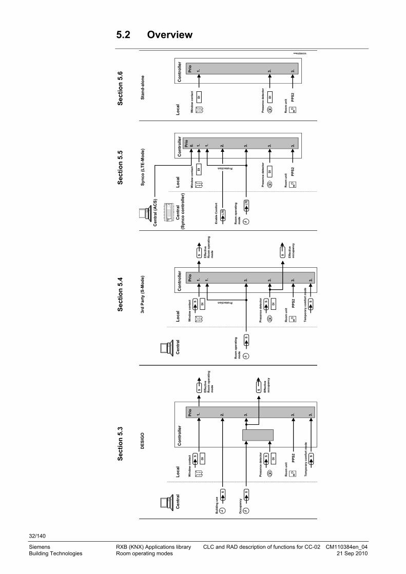
5.2 Overview
Sec
tio
n 5
.3
Sec
tio
n 5
.4
S
ecti
on
5.5
Sec
tio
n 5
.6
PP
S2
S
Pre
sen
ce d
etec
tor
Ro
om
un
it
Oc
cu
pan
cy
Bu
ildin
g u
se
Win
do
w c
on
tact
Ce
ntr
alL
oca
l
1. 2.
3.
SD
I
S S
S
DI
Eff
ecti
veR
oo
m o
per
atin
gm
od
e
S
Eff
ecti
veo
ccu
pan
cy
DE
SIG
O
3.
Co
ntr
olle
r
PP
S2
S
Cen
tral
Lo
cal
1.
3.
SD
I
S
S
DI
3rd
Par
ty (
S-M
od
e)
3.
Co
ntr
olle
r
1.
3.Protection
PP
S2
Ce
ntr
alL
oca
l
1. 2.
3.
DI
LTE
DI
Sy
nco
(L
TE
-Mo
de
)
3.
Co
ntr
olle
r
1. 3.
En
able
Co
mfo
rt LTE
Pri
oP
rio
Pri
o
Lo
cal
1.
DI
DI
Sta
nd
-alo
ne
3.
Co
ntr
oll
er
3.
Pri
o
10385Z54en
Tem
po
rary
co
mfo
rt m
od
e
3.
S3.
S
PP
S2
S
Cen
tral
(A
CS
)
0.
(Syn
co c
on
tro
ller)
Ro
om
op
erat
ing
mo
de
Pre
sen
ce d
etec
tor
Ro
om
un
it
Tem
po
rary
co
mfo
rt m
od
e
Eff
ecti
veo
ccu
pan
cy
Eff
ecti
veR
oo
m o
per
atin
gm
od
e
Win
do
w c
on
tact
Win
do
w c
on
tact
Pre
sen
ce d
etec
tor
Ro
om
un
it
Protection
Win
do
w c
on
tact
Pre
sen
ce d
etec
tor
Ro
om
un
it
Ro
om
op
erat
ing
mo
de

33/140
Siemens RXB (KNX) Applications library CLC and RAD description of functions for CC-02 CM110384en_04 Building Technologies Room operating modes 21 Sep 2010
5.3 Determine the room operating mode with DESIGO (S-mode)
In S-mode, the Effective room operating mode of the room controller depends on the central schedules for Use and Occupancy and/or on local influences such as window contacts, presence detectors, or room units.
The illustration below shows how these influences are processed by the room controller along with their priority:
103
85Z
55
PPS2
S
Presence detector
Room unit
Occupancy
Building use
Window contact
Central Local
1.
2.
3.
SDI
S
S
S
DI
Effectiveroom op. mode
S
Effectiveoccupancy
3.
Controller
Prio
Temporary Comfort mode
3.S
The effects of Priority 1 and Priority 2 are similar in nature to states, which apply
continuously The influence of priority 3 is treated as event.
The key point in time is the moment at which the state changes (edge). If another source of third priority later changes the state, the last known change is valid.
STOP
Note!

34/140
Siemens RXB (KNX) Applications library CLC and RAD description of functions for CC-02 CM110384en_04 Building Technologies Room operating modes 21 Sep 2010
5.3.1 Local control of room operating mode via a window contact
S
Central Local
1.
2.
3.
SDI
S
S
S
DI
S
3.
ControllerPrio
PPS2
3.S
If a window is opened, the room controller always switches to room operating mode Protection, i.e. the heating or cooling output is reduced to a minimum. If a window is opened outside the building-in-use period, it is possible to, e.g., trigger an additional alarm in the building automation and control system.
The table below shows the Effective room operating mode as a function of the window contact input. Window contact status
Effective room operating mode
Window closed No effect. Lower-priority inputs determine the operating mode.
Window open Protection.
The window contact is connected directly to a digital input on the room controller (see page 102). Alternatively an EIB/KNX window contact (connected to the bus) may be used. The application evaluates both items of information (logic OR operation). Since EIB/KNX window contacts are available from a variety of manufacturers, the name of the S-mode output communication object varies accordingly.
Raum-Controller RXB...
Window contact input
EIB / KNX window contact
10385Z10en
Window contact outputOR
Window contact on DI
The following S-mode communication object is used to integrate an EIB/KNX window contact:
Window contact input (Input communication object)
Flags
R W C T U
Type Receive timeout States
0 1 1 0 0 1.019
DPT_WindowDoor
No 0 = Closed
1 = Open
Effective room operating mode
Window contact
KNXR
CO

35/140
Siemens RXB (KNX) Applications library CLC and RAD description of functions for CC-02 CM110384en_04 Building Technologies Room operating modes 21 Sep 2010
The state of the room controller (result of the logic OR operation) is mapped to the building automation and control system via the following S-mode communication object:
Window contact output (Output communication object)
Flags
R W C T U
Type Send heartbeat States
1 0 1 1 0 1.019
DPT_WindowDoor
Yes 0 = Closed
1 = Open
Master/slave applications: Bindings are required in S-mode to communicate to the master the window contact state at the slave.
5.3.2 Central control of room operating mode via input from the Use schedule
S
Central Local
1.
2.
3.
SDI
S
S
S
DI
S
3.
ControllerPrio
PPS2
3.S
This schedule determines the overall period of time for which the entire building is in use. Typically, it is used for night setback throughout the building or for long periods when the building is not in use.
When the building is not used, interventions of third priority are disabled. This prevents demand signals from being sent to the primary plant when e.g. a security guard enters a room.
The table below shows the three possible occupancy states and the resulting Effective room operating mode.
Switching state Description Effective room operating mode
Building in use Full availability of all plants. Building enabled for use. Priority 3 influences are enabled (schedule
occupancy, presence detector, room unit, and Temporary Comfort mode).
According to schedule occupancy, presence detector, or room unit
Building not in use Reduced availability of the plants. Priority 3 influences are disabled (schedule
occupancy, presence detector, room unit, and Temporary Comfort mode).
Application: For temporary vacancy. The building must reach the Comfort temperature within hours.
Economy
Protection Setpoints are at levels required to protect the building.
Priority 3 influences are disabled (schedule occupancy, presence detector, room unit, and Temporary Comfort mode).
Application: Extended building vacancy.
Protection
KNXR
CO
Note
Effective room operating mode

36/140
Siemens RXB (KNX) Applications library CLC and RAD description of functions for CC-02 CM110384en_04 Building Technologies Room operating modes 21 Sep 2010
The following S-mode communication object is used for schedule usage from a building automation and control system:
Time schedule Use (input communication object)
Flags
R W C T U
Type Receive timeout States
0 1 1 0 0 20.002
DPT_BuildingMode
Yes 0 = In use 1 = Not in use 2 = Protection
5.3.3 Central and local control of room operating mode based on occupancy
S
Central Local
1.
2.
3.
SDI
S
S
S
DI
S
3.
ControllerPrio
PPS2
3.S
The Effective occupancy is determined by the occupancy schedule and the presence detector. It controls the room operating mode of a room controller while the building is in use.
The central time schedule transmits the anticipated occupancy of a room or group of rooms. It controls the room operating mode of a room controller while the building is in use. Outside the building-in-use period, the time schedule is disabled.
The time schedule can be used, e.g. by a building tenant to specify occupancy times of his or her rooms.
The occupancy schedule has three possible states:
State Description
Occupied Occupancy expected. Room controller switches to Comfort.
Standby Occupancy is probable; the room must be ready for use shortly (Comfort temperature).
Room controller switches to Precomfort.
Unoccupied No occupancy expected. Room controller switches to Economy.
A presence detector detects the presence of people in a room.
It controls the room operating mode of a room controller while the building is in use. Outside the building-in-use period, it is disabled.
KNXR
CO
Occupancy schedule
Presence detector

37/140
Siemens RXB (KNX) Applications library CLC and RAD description of functions for CC-02 CM110384en_04 Building Technologies Room operating modes 21 Sep 2010
The presence detector has two states:
State Description
Occupied Room is occupied. Room controller switches to Comfort.
Unoccupied Room is not occupied. Room controller switches to Economy or Precomfort.
The table below shows Effective occupancy as a function of the occupancy time schedule and the presence detector. Rule: Occupied takes precedence over unoccupied. If either the schedule or the presence detector transmits occupied, the room is occupied.
Presence detector Occupancy schedule Effective occupancy
No schedule. Occupied.
Occupied. Occupied.
Standby. Standby.
No presence detector
Unoccupied. Unoccupied.
No schedule. Unoccupied.
Occupied. Occupied.
Standby. Standby.
Unoccupied (no people present).
Unoccupied. Unoccupied.
No schedule. Occupied.
Occupied. Occupied.
Standby. Occupied.
Occupied (people present).
Unoccupied. Occupied.
The Effective room operating mode can be changed by the Effective occupancy only
during the building-in-use period (defined by the Use schedule). The change in the Effective room operating mode is event-driven at exactly the time
when the Effective occupancy changes. The room unit or Temporary Comfort mode (both priority 3) can cause the Effective
room operating mode to change again last command wins. Effective occupancy Effective room operating
mode
Occupied. Comfort.
Standby. Precomfort.
Unoccupied. Economy.
Key: Occupied means: "changes to occupied ". The following S-mode communication object is used for schedule usage from a building automation and control system:
Time scheduler Occupancy (input communication object)
Flags
R W C T U
Type Receive timeout States
0 1 1 0 0 20.003
DPT_OccMode
Yes 0 = Occupied
1 = Standby
2 = Unoccupied
Effective occupancy
Effective room operating mode
KNXR
CO

38/140
Siemens RXB (KNX) Applications library CLC and RAD description of functions for CC-02 CM110384en_04 Building Technologies Room operating modes 21 Sep 2010
The presence detector is connected directly to a digital input on the room controller (see page 102); alternatively an EIB/KNX presence detector connected to the EIB/KNX bus may be used (see diagram below). The two entries are OR-linked; if one of them signals presence, presence applies. Since EIB/KNX presence detectors are available from a variety of manufacturers, the name of the S-mode output communication object varies accordingly.
Room controller RXB...
Presence detector input
EIB / KNX presence detector
10385Z07en
Presence detector on DI
OR
Presence detector output
Delay on / off Without delay The following S-mode communication object is used to integrate a presence detector connected to the bus:
Presence detector input (output communication object)
Flags
R W C T U
Type Receive timeout States
1 0 1 1 0 1.018
DPT_Occupancy
Yes 0 = Unoccupied
1 = Occupied
The state of the local presence detector on the digital input is mapped in the building automation and control system via the following S-mode output communication object:
Presence detector output (input communication object)
Flags
R W C T U
Type Send heartbeat States
0 1 1 0 0 1.018
DPT_Occupancy
No 0 = Unoccupied
1 = Occupied
Master/slave applications Bindings are required in S-mode, in order to transmit the slave presence detector status to the master.
Effective occupancy
S
Zentral Lokal
1.
2.
3.
SDI
S
S
S
DI
S
3.
ControllerPrio
PPS2
3.S
The output communication object Effective occupancy shows the occupancy status of the room (based on a combination of time schedule and presence detector). In the case of integration into a building automation and control system, the data is mapped to the following output communication object:
Presence detector
KNXR
CO
Note

39/140
Siemens RXB (KNX) Applications library CLC and RAD description of functions for CC-02 CM110384en_04 Building Technologies Room operating modes 21 Sep 2010
Effective occupancy (output communication object)
Flags
R W C T U
Type Send heartbeat States
1 0 1 1 0 20.003
DPT_OccMode
Yes 0 = Occupied
1 = Standby
2 = Unoccupied
5.3.4 Central control of room operating mode via room operating mode schedule
DESIGO does not support this type of schedule. If nevertheless used, the room controller may produce errors.
5.3.5 Local control of room operating mode with a room unit
Room unit
S
Central Local
1.
2.
3.
SDI
S
S
S
DI
S
3.
ControllerPrio
PPS2
3.S
The /Auto button on the room unit can be used like a presence button. The room user can raise or reduce the room temperature.
The room unit is connected to the PPS2 interface on the room controller. It displays the Effective room operating mode in a simplified form, and can also be used to change it.
State Description
Auto Effective room operating mode is Comfort.
Reduced operation in the room, dependent on priority 1, 2 and 3 influences. The Effective room operating mode is Precomfort, Economy, or Protection (3rd priority:: Last one wins).
The Effective room operating mode on the room unit can be changed only during the
building-in-use period (Use schedule). The change in the Effective room operating mode is event-driven, the event being
the moment when the button on the room unit is pressed. The Effective occupancy or Temporary Comfort mode (both priority 3) can cause the
Effective room operating mode to change again last command wins.
Effective room operating mode

40/140
Siemens RXB (KNX) Applications library CLC and RAD description of functions for CC-02 CM110384en_04 Building Technologies Room operating modes 21 Sep 2010
The table below shows the effect of the /Auto button on the Effective room operating mode of the room controller.
Existing Effective room op. mode
Room unit display
Manual operation of /Auto button
New Effective room operating mode
Comfort Auto Precomfort if Effective occupancy = occupied or standby. Economy if Effective occupancy = unoccupied.
Precomfort Auto Comfort
Economy Auto Comfort for Temporary Comfort period 1)
Protection Auto Protection, unchanged.
Key: Auto means: "changes to Auto ". 1) Comfort mode is active for the predefined Temporary Comfort period (see page
103). The room controller then returns to Economy.
5.3.6 Local control of room operating mode via the Temporary Comfort mode input
KNXR
CO
S
Central Local
1.
2.
3.
SDI
S
S
S
DI
S
3.
ControllerPrio
PPS2
3.S
The Temporary Comfort mode communication object has an effect similar to that of the /Auto button on the room unit. However, HVAC control can only be enabled, i.e. the room operating mode switches to Comfort only.
Any KNX/EIB button (pulse switch) can be used for entry:
RXB... room controllerEIB / KNX button
Temporary Comfort mode
10385Z59de The following S-mode communication object is used to integrate a bus button:
Temporary Comfort mode (input communication object)
Flags
R W C T U
Type Receive timeout States
0 1 1 0 0 1.017
DPT_Trigger
No 1 = Trigger
0 = Not used
KNXR
CO
41/140
Siemens RXB (KNX) Applications library CLC and RAD description of functions for CC-02 CM110384en_04 Building Technologies Room operating modes 21 Sep 2010
The communication object Temporary Comfort mode has two possible states:
State Description
1 = Trigger Effective room operating mode is Comfort.
0 = Not used Has no influence on the Effective room operating mode.
The change in the Effective room operating mode with Temporary Comfort mode
only during the building-in-use period (Use schedule). The change in the Effective room operating mode is event-driven at the moment
when the communication object is received. The Effective occupancy or the room unit (both priority 3) can cause the Effective
room operating mode to change again last command wins. The table below shows the effect of the Temporary Comfort mode on the Effective room operating mode of the room controller.
Existing Effective room op. mode
Temporary Comfort mode
New Effective room operating mode
Comfort 0 = Not used No effect.
Precomfort 1 = Trigger Comfort.
Economy 1 = Trigger Comfort for Temporary Comfort period 1).
Protection 1 = Trigger Protection, unchanged.
Key: 1 means: "changes to 1 ". 1) Comfort mode is active for the predefined Temporary Comfort period (see page
103). The room controller then returns to Economy.
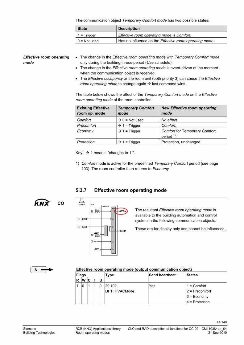
5.3.7 Effective room operating mode
KNXR
CO S
Central Local
1.
2.
3.
SDI
S
S
S
DI
S
3.
ControllerPrio
PPS2
3.S
The resultant Effective room operating mode is available to the building automation and control system in the following communication objects.
These are for display only and cannot be influenced.
Effective room operating mode (output communication object)
Flags
R W C T U
Type Send heartbeat States
1 0 1 1 0 20.102
DPT_HVACMode
Yes 1 = Comfort
2 = Precomfort
3 = Economy
4 = Protection
Effective room operating mode
42/140
Siemens RXB (KNX) Applications library CLC and RAD description of functions for CC-02 CM110384en_04 Building Technologies Room operating modes 21 Sep 2010
The resultant Effective room operating mode is also available as 4 digital communication objects:
Effective room operating mode Comfort (output communication object) Effective room operating mode Precomfort (output communication object) Effective room operating mode Economy (output communication object) Effective room operating mode Protection (output communication object)
Flags
R W C T U
Type Send heartbeat States
1 0 1 1 0 1.001
DPT_Switch
Yes 0 = Off
1 = On
5.3.8 DESIGO examples
The following examples show two typical applications of schedules and local control of the room operating mode. Rooms without room unit or presence detector
The room operating mode of rooms 1…3 in a building is determined by the two schedules Use and Occupancy. Window contacts are installed in all rooms.
The following conditions are specified:
The building is in use from 06.00 to 22.00 (Use schedule). Outside this period the opening of a window trips an alarm (2).
Rooms 1 ... 3 are used by the same tenant and are controlled by the common schedule occupancy: Night setback is between 17.00 to 8.00 (not occupied), lunch between 12.00 and 13.00 (standby).
In Room 3, the window is opened briefly once in the morning and once at night (1).
Example 1
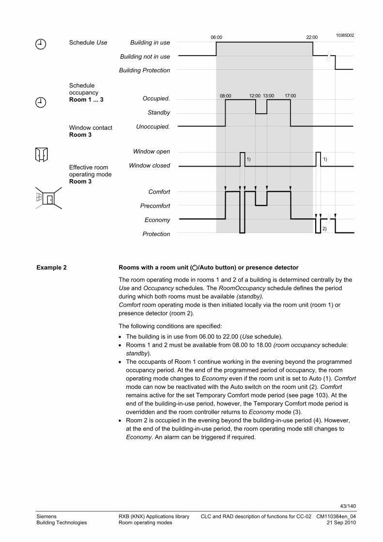
43/140
Siemens RXB (KNX) Applications library CLC and RAD description of functions for CC-02 CM110384en_04 Building Technologies Room operating modes 21 Sep 2010
Schedule Use
Schedule occupancy Room 1 ... 3 Window contact Room 3
Effective room operating mode Room 3
Building in use
Building not in use
Building Protection
Occupied.
Standby
Unoccupied.
Window open
Window closed
Comfort
Precomfort
Economy
Protection
06:00 22:00
08:00 17:0013:0012:00
10385D02
1)
2)
1)
Rooms with a room unit ( /Auto button) or presence detector
The room operating mode in rooms 1 and 2 of a building is determined centrally by the Use and Occupancy schedules. The RoomOccupancy schedule defines the period during which both rooms must be available (standby). Comfort room operating mode is then initiated locally via the room unit (room 1) or presence detector (room 2).
The following conditions are specified:
The building is in use from 06.00 to 22.00 (Use schedule). Rooms 1 and 2 must be available from 08.00 to 18.00 (room occupancy schedule:
standby). The occupants of Room 1 continue working in the evening beyond the programmed
occupancy period. At the end of the programmed period of occupancy, the room operating mode changes to Economy even if the room unit is set to Auto (1). Comfort mode can now be reactivated with the Auto switch on the room unit (2). Comfort remains active for the set Temporary Comfort mode period (see page 103). At the end of the building-in-use period, however, the Temporary Comfort mode period is overridden and the room controller returns to Economy mode (3).
Room 2 is occupied in the evening beyond the building-in-use period (4). However, at the end of the building-in-use period, the room operating mode still changes to Economy. An alarm can be triggered if required.
Example 2

44/140
Siemens RXB (KNX) Applications library CLC and RAD description of functions for CC-02 CM110384en_04 Building Technologies Room operating modes 21 Sep 2010
Schedule Use Schedule occupancy Room 1 and 2
/ Auto button on room unit Room 1 Effective room operating mode Room 1 Presence detector Room 2 Effective room operating mode Room 2
Building in use
Building not in use
Building Protection
Occupied
Standby
Unoccupied
Auto
Comfort
Precomfort
Economy
Protection
Occupied
Unoccupied
Comfort
Precomfort
Economy
Protection
06:00 22:00
08:00 18:00
10385D03
1)
1)
2)
2)
3)
3)
4)
4)

45/140
Siemens RXB (KNX) Applications library CLC and RAD description of functions for CC-02 CM110384en_04 Building Technologies Room operating modes 21 Sep 2010
5.4 Determine the room operating mode with third-party products (S-mode)
In S-mode, the Effective room operating mode of the room controller depends on the central Room operating mode schedule and/or on local influences such as window contact, presence detector, or room unit.
The illustration below shows how these influences are processed by the room controller along with their priority:
PPS2
S
Central Local
1.
3.
SDI
S
S
DI
Effectiveroom op. mode
3.
Controller
1.
3.
Room operating mode
Pro
tec
tio
n m
od
e
Window contact
Presence detector
Room unit
Prio
103
85
Z5
6
3.
TemporaryComfort mode
S
S
Effectiveoccupancy
The influence of priorities 1 and 2 is equivalent to permanent states. The influence of priority 3 is treated as event.
The key point in time is the moment at which the state changes (edge). If another source of third priority later changes the state, the last known change is valid.
STOP Important!

46/140
Siemens RXB (KNX) Applications library CLC and RAD description of functions for CC-02 CM110384en_04 Building Technologies Room operating modes 21 Sep 2010
5.4.1 Local control of room operating mode via window contact input
PPS2
S
Central Local
1.
3.
SDI
S
S
DI
3.
Controller
1.
3.
Prio
3.S
S
If a window is opened, the room controller always switches to room operating mode Protection, i.e. the heating or cooling output is reduced to a minimum.
The table below shows the Effective room operating mode as a function of the window contact input. Window contact state Effective room operating mode
Window closed No effect. Lower-priority inputs determine the operating mode.
Window open Protection.
The window contact is connected directly to a digital input on the room controller (see page 102). Alternatively an EIB/KNX window contact connected to the bus may be used. The application evaluates both items of information (logic OR operation). Since EIB/KNX window contacts are available from a variety of manufacturers, the name of the S-mode output communication object varies accordingly.
Room controller RXB...
Window contact input
EIB / KNX window contact
10385Z10en
Window contact outputOR
Window contact on DI
The following S-mode communication object is used to integrate an EIB/KNX window contact:
Window contact input (input communication object)
Flags
R W C T U
Type Receive timeout States
0 1 1 0 0 1.019
DPT_WindowDoor
No 0 = Closed
1 = Open
Effective room operating mode
Window contact
KNXR
CO

47/140
Siemens RXB (KNX) Applications library CLC and RAD description of functions for CC-02 CM110384en_04 Building Technologies Room operating modes 21 Sep 2010
The state of the room controller (result of the logic OR operation) is mapped to the building automation and control system via the following S-mode output communication object:
Window contact output (output communication object)
Flags
R W C T U
Type Send heartbeat States
1 0 1 1 0 1.019
DPT_WindowDoor
Yes 0 = Closed
1 = Open
Master/slave applications: Bindings are required in S-mode to communicate to the master the window contact state at the slave.
5.4.2 Central control of room operating mode with an input from the room operating mode schedule
PPS2
S
Central Local
1.
3.
SDI
S
S
DI
3.
Controller
1.
Prio
3.S
S
3.
The room operating mode can be specified directly with the communication object room operating mode.
The following S-mode communication object is used to control the room operating mode from a building automation and control system:
Room operating mode schedule (input communication object)
Flags
R W C T U
Type Receive timeout States
0 1 1 0 0 20.102
DPT_HVACMode
Yes 1 = Comfort 2 = Precomfort 3 = Economy 4 = Protection
Room operating mode schedule
Effective room operating mode of room controller
Comfort Comfort
Precomfort Precomfort
Economy Economy
Protection Protection
The room operating modes Comfort, Precomfort and Economy have priority 3 fro the
room controller, i.e. they can be changed by a presence detector or room unit. The Protection room operating mode has priority 1, i.e. presence detector and room
units are disabled.
KNXR
CO
Note
Priorities

48/140
Siemens RXB (KNX) Applications library CLC and RAD description of functions for CC-02 CM110384en_04 Building Technologies Room operating modes 21 Sep 2010
5.4.3 Central control of the room operating mode via the schedules Use and Occupancy
Third-party S-mode does not support these schedules. If nevertheless used, the room controller may produce errors.
5.4.4 Central and local control of room operating mode based on occupancy
Presence detector
PPS2
S
Central Local
1.
3.
SDI
S
S
DI
3.
Controller
1.
3.
Prio
3.S
S
A presence detector detects the presence of people in a room.
It controls the room operating mode of a room controller while the building is in use. Outside the building-in-use period, it is disabled.
The presence detector has two states:
State Description
Occupied Room is occupied. Room controller switches to Comfort.
Unoccupied Room is not occupied. Room controller switches to Economy or Precomfort.
The change in the Effective room operating mode is event-driven at exactly the time
when the Effective occupancy changes. The room unit or Temporary Comfort mode (both priority 3) can cause the Effective
room operating mode to change again last command wins. Presence detector New Effective room operating mode
Occupied (people enter room)
Precomfort
Unoccupied (people leave room)
Precomfort if room operating mode from schedule = Comfort or Precomfort Economy if room operating mode from schedule = Economy.
Key: Occupied means: "changes to occupied ". The presence detector is connected directly to a digital input on the room controller (see page 102); alternatively an EIB/KNX presence detector connected to the EIB/KNX bus may be used (see diagram below). The two inputs are OR-linked: If one signals presence, presence applies.
Effective room operating mode
Presence detector

49/140
Siemens RXB (KNX) Applications library CLC and RAD description of functions for CC-02 CM110384en_04 Building Technologies Room operating modes 21 Sep 2010
Since EIB/KNX presence detectors are available from a variety of manufacturers, the name of the S-mode output communication object varies accordingly.
Room controller RXB...
Presence detector input
EIB / KNX presence detector
10385Z07en
Presence detector on DI
OR
Presence detector output
Delay on / off Without delay The following S-mode communication object is used to integrate a presence detector connected to the bus:
Presence detector input (input communication object)
Flags
R W C T U
Type Receive timeout States
1 0 1 1 0 1.018
DPT_Occupancy
Yes 0 = Unoccupied
1 = Occupied The state of the local presence detector on the digital input is mapped in the building automation and control system via the following S-mode output communication object:
Presence detector output (output communication object)
Flags
R W C T U
Type Send heartbeat States
0 1 1 0 0 1.018
DPT_Occupancy
No 0 = Unoccupied
1 = Occupied
Master/slave applications Bindings are required in S-mode, in order to transmit the slave presence detector status to the master.
Effective occupancy
PPS2
S
Central Local
1.
3.
SDI
S
S
DI
3.
Controller
1.
3.
Prio
3.S
S
The output communication object Effective occupancy shows the occupancy status of the room (presence detector). In the case of integration into a building automation and control system, the data is mapped to the following output communication object.
Effective occupancy (output communication object)
Flags
R W C T U
Type Send heartbeat States
1 0 1 1 0 20.003
DPT_OccMode
Yes 0 = Occupied
1 = Standby
2 = Unoccupied
KNXR
CO
Note
.
.
.
.
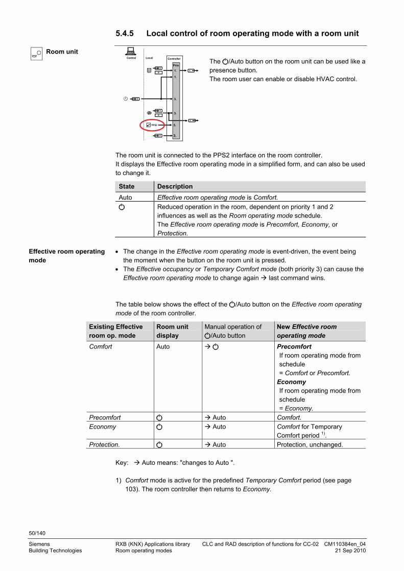
50/140
Siemens RXB (KNX) Applications library CLC and RAD description of functions for CC-02 CM110384en_04 Building Technologies Room operating modes 21 Sep 2010
5.4.5 Local control of room operating mode with a room unit
Room unit
PPS2
S
Central Local
1.
3.
SDI
S
S
DI
3.
Controller
1.
3.
Prio
3.S
S
The /Auto button on the room unit can be used like a presence button. The room user can enable or disable HVAC control.
The room unit is connected to the PPS2 interface on the room controller. It displays the Effective room operating mode in a simplified form, and can also be used to change it.
State Description
Auto Effective room operating mode is Comfort.
Reduced operation in the room, dependent on priority 1 and 2 influences as well as the Room operating mode schedule. The Effective room operating mode is Precomfort, Economy, or Protection.
The change in the Effective room operating mode is event-driven, the event being
the moment when the button on the room unit is pressed. The Effective occupancy or Temporary Comfort mode (both priority 3) can cause the
Effective room operating mode to change again last command wins. The table below shows the effect of the /Auto button on the Effective room operating mode of the room controller.
Existing Effective room op. mode
Room unit display
Manual operation of /Auto button
New Effective room operating mode
Comfort Auto Precomfort If room operating mode from schedule = Comfort or Precomfort.
Economy If room operating mode from schedule = Economy.
Precomfort Auto Comfort.
Economy Auto Comfort for Temporary Comfort period 1).
Protection. Auto Protection, unchanged.
Key: Auto means: "changes to Auto ". 1) Comfort mode is active for the predefined Temporary Comfort period (see page
103). The room controller then returns to Economy.
Effective room operating mode
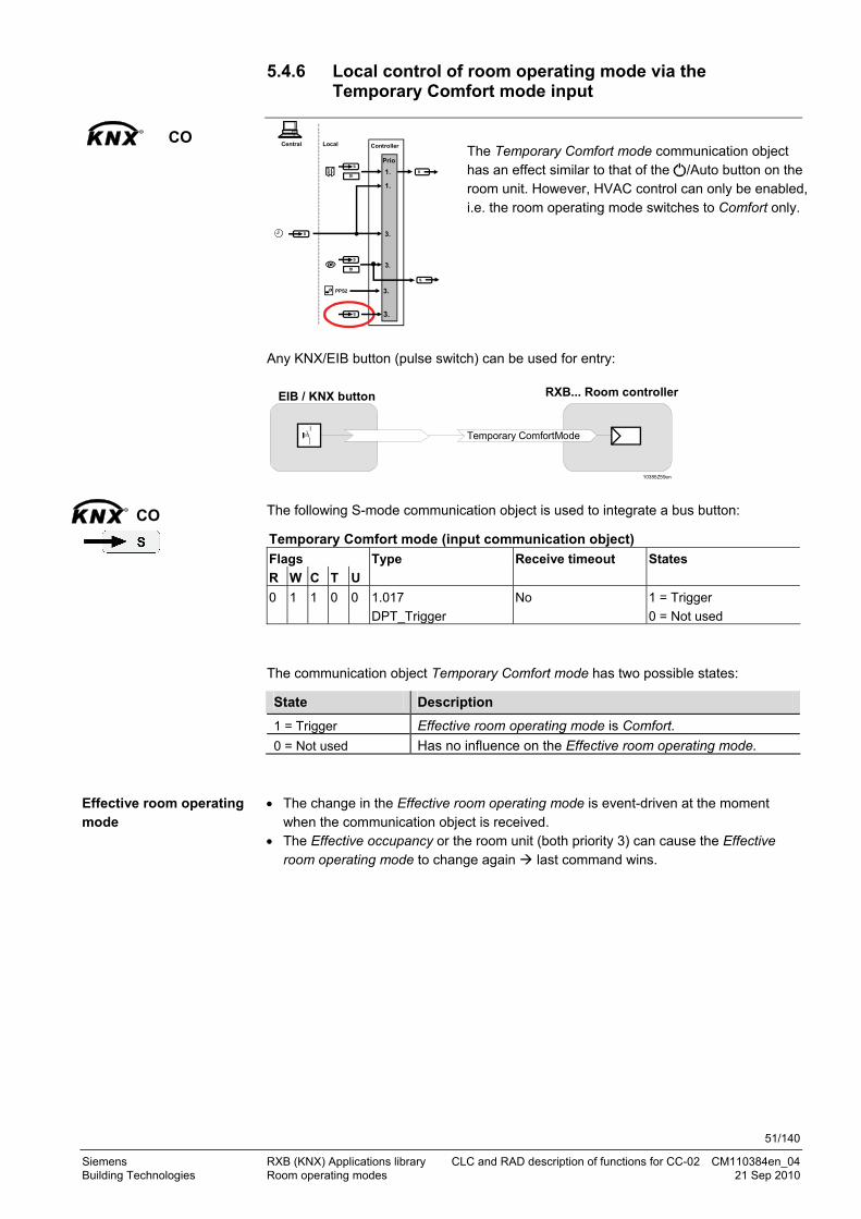
51/140
Siemens RXB (KNX) Applications library CLC and RAD description of functions for CC-02 CM110384en_04 Building Technologies Room operating modes 21 Sep 2010
5.4.6 Local control of room operating mode via the Temporary Comfort mode input
KNXR
CO
PPS2
S
Central Local
1.
3.
SDI
S
S
DI
3.
Controller
1.
3.
Prio
3.S
S
The Temporary Comfort mode communication object has an effect similar to that of the /Auto button on the room unit. However, HVAC control can only be enabled, i.e. the room operating mode switches to Comfort only.
Any KNX/EIB button (pulse switch) can be used for entry:
RXB... Room controllerEIB / KNX button
Temporary ComfortMode
10385Z59en The following S-mode communication object is used to integrate a bus button:
Temporary Comfort mode (input communication object)
Flags
R W C T U
Type Receive timeout States
0 1 1 0 0 1.017
DPT_Trigger
No 1 = Trigger
0 = Not used
The communication object Temporary Comfort mode has two possible states:
State Description
1 = Trigger Effective room operating mode is Comfort.
0 = Not used Has no influence on the Effective room operating mode.
The change in the Effective room operating mode is event-driven at the moment
when the communication object is received. The Effective occupancy or the room unit (both priority 3) can cause the Effective
room operating mode to change again last command wins.
KNXR
CO
Effective room operating mode

52/140
Siemens RXB (KNX) Applications library CLC and RAD description of functions for CC-02 CM110384en_04 Building Technologies Room operating modes 21 Sep 2010
The table below shows the effect of the Temporary Comfort mode on the Effective room operating mode of the room controller.
Existing Effective room op. mode
Temporary Comfort mode
New Effective room operating mode
Comfort 0 = Not used No effect.
Precomfort 1 = Trigger Comfort.
Economy 1 = Trigger Comfort for Temporary Comfort period 1).
Protection. 1 = Trigger Protection, unchanged.
Key: 1 means: "changes to 1 ". 1) Comfort mode is active for the predefined Temporary Comfort period (see page
103). The room controller then returns to Economy.
5.4.7 Effective room operating mode
PPS2
S
Central Local
1.
3.
SDI
S
S
DI
3.
Controller
1.
3.
Prio
3.S
S
The resultant Effective room operating mode is available to the building automation and control system in the following communication objects.
These are for display only and cannot be influenced.
Effective room operating mode (output communication object)
Flags
R W C T U
Type Send heartbeat States
1 0 1 1 0 20.102
DPT_HVACMode
Yes 1 = Comfort
2 = Precomfort
3 = Economy
4 = Protection
The resultant Effective room operating mode is also available as 4 digital communication objects:
Effective room operating mode Comfort (output communication object) Effective room operating mode Precomfort (output communication object) Effective room operating mode Economy (output communication object) Effective room operating mode Protection (output communication object)
Flags
R W C T U
Type Send heartbeat States
1 0 1 1 0 1.001
DPT_Switch
Yes 0 = Off
1 = On

53/140
Siemens RXB (KNX) Applications library CLC and RAD description of functions for CC-02 CM110384en_04 Building Technologies Room operating modes 21 Sep 2010
5.4.8 Third-party (S-mode) examples
The following examples show two typical applications of schedules and local control of the room operating mode. Rooms without room unit or presence detector
The room operating mode in Rooms 1..3 of a building is determined by the room operating mode schedule. Window contacts are installed in all rooms.
The following conditions are specified:
Overall, the building is in use from 06.00 to 20.00. The rooms are used and controlled by the room operating mode schedule as follows:
– Night setback from 17.00 to 08.00, – Protection from 20.00 to 06.00 – Lunch from 12.00 to 13.00 (Precomfort).
In Room 3, the window is opened briefly once in the morning and once at night (1).
Room operating mode schedule Window contact Room 3
Effective room operating mode Room 3
Comfort
Precomfort
Economy
Protection
Window open
Window closed
Comfort
Precomfort
Economy
Protection
08:00 17:0013:0012:0010385D04
1)
06:00 20:00
1)
Rooms with room unit ( /Auto button) or presence detector
The room operating mode in rooms 1 and 2 of a building is determined centrally by the room operating mode schedule. Comfort room operating mode is then initiated locally via the room unit (room 1) or presence detector (room 2).
Example 1
Example 2

54/140
Siemens RXB (KNX) Applications library CLC and RAD description of functions for CC-02 CM110384en_04 Building Technologies Room operating modes 21 Sep 2010
The following conditions are specified:
The building is in use from 06.00 to 20.00 (Protection from 20.00 to 06.00).
Rooms 1 and 2 must be available from 08.00 to 18.00 (Precomfort). The occupant(s) of room 1 are working overtime. At 18.00, the room operating mode
changes to Economy, even if the room unit is set to Auto (1). Comfort mode can now be reactivated with the Auto switch on the room unit (2). Comfort remains active for the set Temporary Comfort mode period (see page 103). In Protection mode, however, the Temporary Comfort period is also overridden and the room operating mode changes to Protection (3).
Room 2 is occupied in the evening beyond the building-in-use period (4). However, at the end of the building-in-use period, the room operating mode still changes to Protection. An alarm can be triggered if required.
Room operating mode schedule
Room with room unit
/ Auto button on room unit Room 1 Effective room operating mode Room 1
Room without room unit
Presence detector Room 2 Effective room operating mode Room 2
Comfort
Precomfort
Economy
Protection
Auto
Comfort
Precomfort
Economy
Protection
Occupied
Unoccupied
Comfort
Precomfort
Economy
Protection
08:00 18:00
10385D05
1)
1)
2)
2)
3)
3)
4)
4)
06:00 20:00

55/140
Siemens RXB (KNX) Applications library CLC and RAD description of functions for CC-02 CM110384en_04 Building Technologies Room operating modes 21 Sep 2010
5.5 Determine the room operating mode with Synco (LTE mode)
In LTE-mode, the Effective room operating mode of the room controller depends on the central room operating mode schedule and/or on local influences such as window contact, presence detector, or room unit.
The illustration below shows how these influences are processed by the room controller along with their priority:
PPS2
Central Local
1.
2.
3.
DI
LTE
DI
3.
Controller
1.
3.
Enable Comfort
LTE
Prio
103
85Z
57en
Central (ACS)
0.
(Synco controller)
Window contact
Presence detector
Room unit
Pro
tect
ion
Room operatingmode
If the room operating mode in the ACS (operating booklet) is AUTO, the priorities
1 to 3 apply. If the room operating mode in the ACS (operating booklet) is Comfort, Precomfort, Economy or Protection, these modes have absolute priority ("Prio 0").
The effects of Priority 1 and Priority 2 are similar in nature to states, which apply continuously
The influence of priority 3 is treated as event. The key point in time is the moment at which the state changes (edge). If another source of third priority later changes the state, the last known change is valid.
STOP
Note!

56/140
Siemens RXB (KNX) Applications library CLC and RAD description of functions for CC-02 CM110384en_04 Building Technologies Room operating modes 21 Sep 2010
5.5.1 Local control of room operating mode via window contact input
Window contact
PPS2
Central (Synco controller)
Local
1.
2.
3.
DI
DI
3.
Controller
3.
Prio
1.
Central (ACS)
0.
If a window is opened, the room controller always switches to room operating mode Protection, i.e. the heating or cooling output is reduced to a minimum.
The table below shows the Effective room operating mode as a function of the window contact input. Window contact state Effective room operating mode
Window closed No effect. Lower-priority inputs determine the operating mode.
Window open Protection.
The window contact is connected directly to a digital input of the room controller (see page 102). Master/slave applications: LTE mode does not allow for communicating to the master the slave's window switch state.
5.5.2 Central room operating mode control via Enable Comfort
PPS2
Central (Synco controller)
Local
1.
2.
3.
DI
DI
3.
Controller
3.
Prio
1.
Central (ACS)
0.
A central operator station can use the enable Comfort input to specify whether the room operating mode can be switched to a higher mode than Economy, i.e. if priority 3 influences (room operating mode input, presence detector, room unit) are enabled.
However, the room controller can be used to force enabling of priority 3 influences via local Comfort mode by ignoring enable Comfort.
Effective room operating mode
Note

57/140
Siemens RXB (KNX) Applications library CLC and RAD description of functions for CC-02 CM110384en_04 Building Technologies Room operating modes 21 Sep 2010
The following LTE-mode communication object is provided for central control:
Enable Comfort (input)
Possible partner function blocks) Known partner devices
EnableComfort
Timeswitch zone
110 HVACS HVAC-Mode Scheduler
104 PMC Programs to HVAC-Mode Conversion
Siemens: Synco RMB795
Possible states are:
State Description
Enabled Priority 3 influences (room operating mode input, presence detector, room unit) are enabled.
Disabled Priority 3 influences are disabled. The effective room operating mode is Economy.
Comfort and Precomfort are enabled locally in the controller with the following parameter in the Room unit menu on page 114.
Parameter: Local Comfort mode Description HandyTool
Change from Economy to Precomfort or Comfort mode. *105
Enabled (basic setting) Precomfort or Comfort can be disabled via the Enable Comfort input.
1
Disabled (ignore Enable Comfort input). Precomfort or Comfort CANNOT be disabled via the Enable Comfort input.
0
5.5.3 Central control of room operating mode via room operating mode input
PPS2
Central (Synco controller)
Local
1.
2.
3.
DI
DI
3.
Controller
3.
Prio
1.
Central (ACS)
0.
The following LTE mode communication object is used to control the room operating mode from a building automation and control system:
Room operating mode (input)
Possible partner function blocks) Known partner devices
HVACMode
Timeswitch zone
110 HVACS HVAC-Mode Scheduler
104 PMC Programs to HVAC-Mode Conversion
Siemens: Synco RMU710 / 20 / 30 RMH760 / RMB795
KNXR
CO
KNXR
CO

58/140
Siemens RXB (KNX) Applications library CLC and RAD description of functions for CC-02 CM110384en_04 Building Technologies Room operating modes 21 Sep 2010
Possible states are:
Room operating mode Effective room operating mode of room controller
Comfort Comfort
Precomfort Precomfort
Economy Economy
Protection Protection
The room operating modes Comfort, Precomfort and Economy have priority 3 fro the
room controller, i.e. they can be changed by a presence detector or room unit. The Protection room operating mode has priority 1, i.e. presence detector and room
units are disabled.
5.5.4 Local control of room operating mode via presence detector
Presence
detector
PPS2
Central (Synco controller)
Local
1.
2.
3.
DI
DI
3.
Controller
3.
Prio
1.
Central (ACS)
0.
A presence detector detects the presence of people in a room.
The presence detector is connected directly to a digital input of the room controller (see page 102). Master/slave applications: LTE mode does not allow for communicating to the master the slave's presence detector state. The table below shows the two possible occupancy states and the resulting Effective room operating modes.
Switching state Effective room operating mode
Occupied (people enter room)
Comfort
Unoccupied (people leave room)
Precomfort if room operating mode = Comfort or Precomfort Economy if room operating mode = Economy
Key: Occupied means: "changes to occupied ".
Priorities
Note
Effective room operating mode

59/140
Siemens RXB (KNX) Applications library CLC and RAD description of functions for CC-02 CM110384en_04 Building Technologies Room operating modes 21 Sep 2010
5.5.5 Local control of room operating mode with a room unit
Room unit
PPS2
Central (Synco controller)
Local
1.
2.
3.
DI
DI
3.
Controller
3.
Prio
1.
Central (ACS)
0.
The /Auto button on the room unit can be used like a presence button. The room user can enable or disable HVAC control.
The room unit is connected to the PPS2 interface on the room controller. It displays the Effective room operating mode in a simplified form, and can also be used to change it.
State Description
Auto Effective room operating mode is Comfort.
Reduced operation in the room, dependent on priority 1, 2 and 3 influences. The Effective room operating mode is Precomfort, Economy, or Protection.
The change in the Effective room operating mode is event-driven at the moment
when the button on the room unit is pressed. The Effective occupancy can cause the Effective room operating mode to change
again last command wins. The table below shows the effect of the /Auto button on the Effective room operating mode of the room controller.
Existing Effective room op. mode
Room unit display
Manual operation of /Auto button
New Effective room operating mode
Comfort Auto Precomfort if room operating mode from schedule = Comfort or Precomfort.
Economy if room operating mode from schedule = Economy.
Precomfort Auto Comfort.
Economy Auto Comfort for Temporary Comfort period 1).
Protection Auto Protection, unchanged.
Key: Auto means: "changes to Auto ". 1) Comfort mode is active for the predefined Temporary Comfort period (see page
103). The room controller then returns to Economy.
Effective room operating mode

60/140
Siemens RXB (KNX) Applications library CLC and RAD description of functions for CC-02 CM110384en_04 Building Technologies Room operating modes 21 Sep 2010
5.5.6 LTE mode examples
The following examples show two typical applications of the schedule program and local control of the room operating mode. Rooms without room unit or presence detector
The room operating mode in Rooms 1..3 of a building is determined by the room operating mode schedule. Window contacts are installed in all rooms.
The following conditions are specified:
Overall, the building is in use from 06.00 to 20.00. The rooms are used and controlled by the room operating mode schedule as follows:
– Night setback from 17.00 to 08.00, – Protection from 20.00 to 06.00 – Lunch from 12.00 to 13.00 (Precomfort).
In Room 3, the window is opened briefly once in the morning and once at night (1).
Room operating mode schedule Window contact Room 3
Effective room operating mode Room 3
Comfort
Precomfort
Economy
Protection
Window open
Window closed
Comfort
Precomfort
Economy
Protection
08:00 17:0013:0012:0010385D04
1)
06:00 20:00
1)
Rooms with room unit ( /Auto button) or presence detector
The room operating mode in rooms 1 and 2 of a building is determined centrally by the room operating mode schedule. Comfort room operating mode is then initiated locally via the room unit (room 1) or presence detector (room 2).
Example 1
Example 2
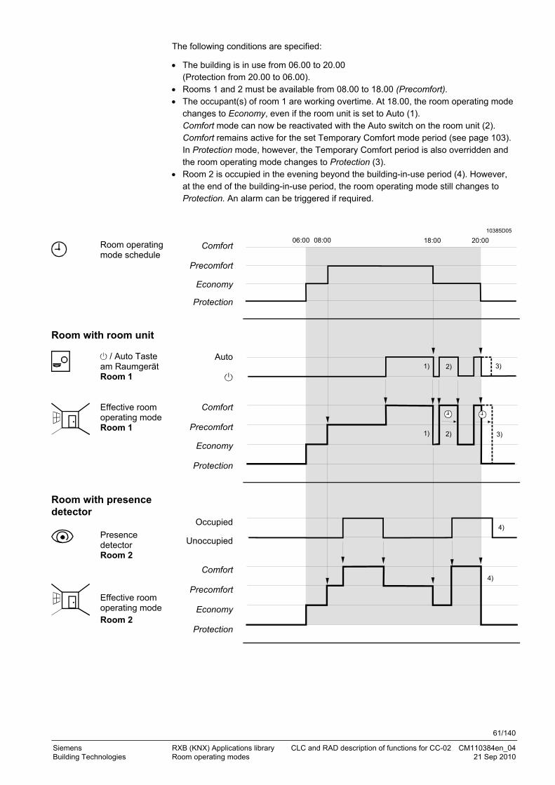
61/140
Siemens RXB (KNX) Applications library CLC and RAD description of functions for CC-02 CM110384en_04 Building Technologies Room operating modes 21 Sep 2010
The following conditions are specified:
The building is in use from 06.00 to 20.00 (Protection from 20.00 to 06.00).
Rooms 1 and 2 must be available from 08.00 to 18.00 (Precomfort). The occupant(s) of room 1 are working overtime. At 18.00, the room operating mode
changes to Economy, even if the room unit is set to Auto (1). Comfort mode can now be reactivated with the Auto switch on the room unit (2). Comfort remains active for the set Temporary Comfort mode period (see page 103). In Protection mode, however, the Temporary Comfort period is also overridden and the room operating mode changes to Protection (3).
Room 2 is occupied in the evening beyond the building-in-use period (4). However, at the end of the building-in-use period, the room operating mode still changes to Protection. An alarm can be triggered if required.
Room operating mode schedule
Room with room unit
/ Auto Taste am Raumgerät Room 1 Effective room operating mode Room 1
Room with presence detector
Presence detector Room 2 Effective room operating mode Room 2
Comfort
Precomfort
Economy
Protection
Auto
Comfort
Precomfort
Economy
Protection
Occupied
Unoccupied
Comfort
Precomfort
Economy
Protection
08:00 18:00
10385D05
1)
1)
2)
2)
3)
3)
4)
4)
06:00 20:00

62/140
Siemens RXB (KNX) Applications library CLC and RAD description of functions for CC-02 CM110384en_04 Building Technologies Room operating modes 21 Sep 2010
5.6 Determine the room operating mode without a bus (stand-alone)
If no bus is connected, the Effective room operating mode of the room controller depends on the local influences such as window contact, presence detector or room unit.
The illustration below shows how these influences are processed by the room controller along with their priority:
PPS2
Local
1.DI
DI
3.
Controller
3.
Window contact
Presence detector
Room unit
Prio
103
85Z
58
The influence of priorities 1 and 2 is equivalent to permanent states. The influence of priority 3 is treated as event.
The key point in time is the moment at which the state changes (edge). If another source of third priority later changes the state, the last known change is valid.
If there is no bus connection, the controller assumes the following defaults:
Use = Building in use. Occupancy = Occupied.
STOP Important!
Note
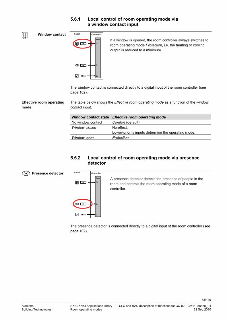
63/140
Siemens RXB (KNX) Applications library CLC and RAD description of functions for CC-02 CM110384en_04 Building Technologies Room operating modes 21 Sep 2010
5.6.1 Local control of room operating mode via a window contact input
Window contact
PPS2
Local
1.DI
DI
3.
Controller
3.
Prio
If a window is opened, the room controller always switches to room operating mode Protection, i.e. the heating or cooling output is reduced to a minimum.
The window contact is connected directly to a digital input of the room controller (see page 102). The table below shows the Effective room operating mode as a function of the window contact input. Window contact state Effective room operating mode
No window contact Comfort (default)
Window closed No effect. Lower-priority inputs determine the operating mode.
Window open Protection.
5.6.2 Local control of room operating mode via presence detector
Presence detector
PPS2
Local
1.DI
DI
3.
Controller
3.
Prio
A presence detector detects the presence of people in the room and controls the room operating mode of a room controller.
The presence detector is connected directly to a digital input of the room controller (see page 102).
Effective room operating mode

64/140
Siemens RXB (KNX) Applications library CLC and RAD description of functions for CC-02 CM110384en_04 Building Technologies Room operating modes 21 Sep 2010
The change in the Effective room operating mode is event-driven at exactly the time when the Effective occupancy changes.
The room unit (which is also priority 3) can cause the Effective room operating mode to change again last command wins.
Presence detector New Effective room operating
mode
No presence detector Comfort (default)
Unoccupied (people leave room).
Economy.
Occupied (people enter room).
Comfort
Key: Occupied means: "changes to occupied ".
5.6.3 Local control of room operating mode with room unit
Room unit
PPS2
Local
1.DI
DI
3.
Controller
3.
Prio
The /Auto button on the room unit can be used like a presence button. The room user can enable or disable HVAC control.
The room unit is connected to the PPS2 interface on the room controller. It displays the Effective room operating mode in a simplified form, and can also be used to change it.
State Description
Auto Effective room operating mode is Comfort.
Reduced operation in the room, dependent on priority 1 or 3 influence: Effective room operating mode is Precomfort, Economy or Protection.
The change in the Effective room operating mode is event-driven at the moment
when the button on the room unit is pressed. The presence detector (which is also priority 3) can cause the Effective room
operating mode to change again last command wins. The table below shows the effect of the /Auto button on the Effective room operating mode of the room controller.
Effective room operating mode
Effective room operating mode

65/140
Siemens RXB (KNX) Applications library CLC and RAD description of functions for CC-02 CM110384en_04 Building Technologies Room operating modes 21 Sep 2010
Existing Effective room op. mode
Room unit display
Manual operation of /Auto button
New Effective room operating mode
Comfort Auto Precomfort if Effective occupancy = Occupied.
Economy if Effective occupancy = Unoccupied.
Precomfort Auto Comfort.
Economy Auto Comfort for Temporary Comfort period 1).
Protection Auto Protection, unchanged.
Key: Auto means: "changes to Auto ". 1) Comfort mode is active for the predefined Temporary Comfort period (see page
103). The room controller then returns to Economy.
5.6.4 Example for stand-alone
The example below shows how local influences interact to affect the room operating mode. Window contacts are installed in all rooms.
If the window is opened (1), the room operating mode changes to Protection and the room unit is switched again to .
Room 1 has a room unit.
As no presence detector is connected, the basic room operating mode is Precomfort and the timer (Temporary Comfort mode time, see page 103) is thus not available. The room unit allows for switching between Precomfort and Comfort (2).
Room 2 has a room unit and a presence detector.
If unoccupied, the basic room operating mode is Economy; if occupied, the room operating mode changes to Comfort (3) and the room unit is set to Auto. The room unit allows for switching between Comfort and Precomfort (2).
Room 3: To force the basic room operating mode Economy, a presence detector in
state unoccupied is simulated at an open digital input (occupied = contact closed, see page 102). The timer is available from Economy. The room has a room unit on which the timer is activated (Temporary Comfort mode period: see page 103). This is where the room operating mode is set to Comfort (2); when the window is opened (3), after timer expiration (4), or after pressing again the /Auto button (5), the room operating mode returns to Economy.

66/140
Siemens RXB (KNX) Applications library CLC and RAD description of functions for CC-02 CM110384en_04 Building Technologies Room operating modes 21 Sep 2010
Window contact Room 1
/ Auto button on room unit Room 1
Effective room operating mode Room 1
Window open
Window closed
Auto
Comfort
Precomfort
Economy
Protection
10385D70
2)
1) 1)
2) 2) 2)
Window contact Room 2 Presence detector Room 2
/ Auto button on room unit Room 2
Effective room operating mode Room 2
Window open
Window closed
Occupied
Unoccupied
Auto
Comfort
Precomfort
Economy
Protection
3)
2)
1) 1)
10385D71
2)
Window contact Room 3
/ Auto button on room unit Room 3
Effective room operating mode Room 3
Window open
Window closed
Auto
Comfort
Precomfort
Economy
Protection.
10385D72
1) 1)
2) 2)
3)
2)
4) 5)
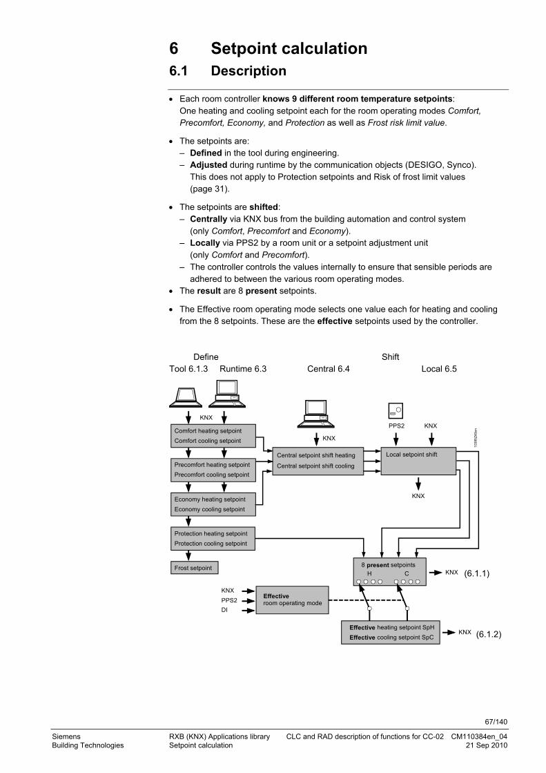
67/140
Siemens RXB (KNX) Applications library CLC and RAD description of functions for CC-02 CM110384en_04 Building Technologies Setpoint calculation 21 Sep 2010
6 Setpoint calculation 6.1 Description
Each room controller knows 9 different room temperature setpoints: One heating and cooling setpoint each for the room operating modes Comfort, Precomfort, Economy, and Protection as well as Frost risk limit value.
The setpoints are: – Defined in the tool during engineering. – Adjusted during runtime by the communication objects (DESIGO, Synco).
This does not apply to Protection setpoints and Risk of frost limit values (page 31).
The setpoints are shifted: – Centrally via KNX bus from the building automation and control system
(only Comfort, Precomfort and Economy). – Locally via PPS2 by a room unit or a setpoint adjustment unit
(only Comfort and Precomfort). – The controller controls the values internally to ensure that sensible periods are
adhered to between the various room operating modes. The result are 8 present setpoints.
The Effective room operating mode selects one value each for heating and cooling from the 8 setpoints. These are the effective setpoints used by the controller.
Define Shift Tool 6.1.3 Runtime 6.3 Central 6.4 Local 6.5
103
85Z
40e
nComfort heating setpoint
Comfort cooling setpoint
Precomfort heating setpoint
Precomfort cooling setpoint
Economy heating setpoint
Economy cooling setpoint
Protection heating setpoint
Protection cooling setpoint
Local setpoint shiftCentral setpoint shift heating
8 present setpoints
Effective heating setpoint SpH
Effective cooling setpoint SpC
H C
PPS2 KNX
Effective room operating mode
Central setpoint shift cooling
Frost setpoint
KNX
KNX
KNX
KNX
PPS2
DI
KNX
KNX
(6.1.1)
(6.1.2)
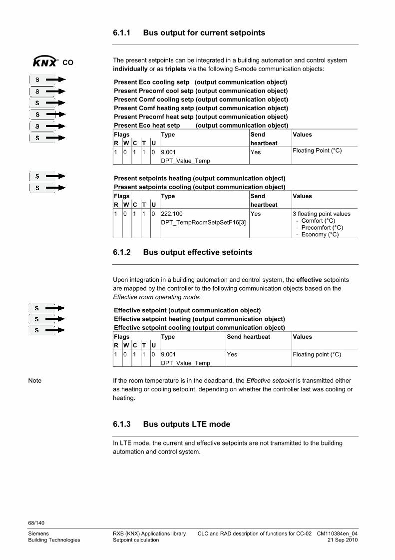
68/140
Siemens RXB (KNX) Applications library CLC and RAD description of functions for CC-02 CM110384en_04 Building Technologies Setpoint calculation 21 Sep 2010
6.1.1 Bus output for current setpoints
The present setpoints can be integrated in a building automation and control system individually or as triplets via the following S-mode communication objects:
Present Eco cooling setp (output communication object) Present Precomf cool setp (output communication object) Present Comf cooling setp (output communication object) Present Comf heating setp (output communication object) Present Precomf heat setp (output communication object) Present Eco heat setp (output communication object)
Flags R W C T U
Type Send
heartbeat
Values
1 0 1 1 0 9.001
DPT_Value_Temp
Yes Floating Point (°C)
Present setpoints heating (output communication object) Present setpoints cooling (output communication object)
Flags
R W C T U
Type Send
heartbeat
Values
1 0 1 1 0 222.100
DPT_TempRoomSetpSetF16[3]
Yes 3 floating point values - Comfort (°C) - Precomfort (°C) - Economy (°C)
6.1.2 Bus output effective setoints
Upon integration in a building automation and control system, the effective setpoints are mapped by the controller to the following communication objects based on the Effective room operating mode:
Effective setpoint (output communication object) Effective setpoint heating (output communication object) Effective setpoint cooling (output communication object)
Flags
R W C T U
Type Send heartbeat Values
1 0 1 1 0 9.001
DPT_Value_Temp
Yes Floating point (°C)
If the room temperature is in the deadband, the Effective setpoint is transmitted either as heating or cooling setpoint, depending on whether the controller last was cooling or heating.
6.1.3 Bus outputs LTE mode
In LTE mode, the current and effective setpoints are not transmitted to the building automation and control system.
KNXR
CO
Note

69/140
Siemens RXB (KNX) Applications library CLC and RAD description of functions for CC-02 CM110384en_04 Building Technologies Setpoint calculation 21 Sep 2010
6.2 Setpoint settings with the tool
A tool is used to set the temperature setpoints for the room operating modes in each room controller. Select the Room Temperature Setpoints tab.
The setpoints can be modified under Room temp setpoints:
ETS3 Professional
ACS Service

70/140
Siemens RXB (KNX) Applications library CLC and RAD description of functions for CC-02 CM110384en_04 Building Technologies Setpoint calculation 21 Sep 2010
HandyTool See the parameters in the last column of the following table.
Name Basic setting Range 1) Resolution Parameter
Protection cooling setpoint 40 °C 10 ... 40 °C 0.5 K *030
Economy cooling setpoint 35 °C 10 ... 40 °C 0.5 K *031
Precomfort cooling setpoint 28 °C 10 ... 40 °C 0.5 K *032
Comfort cooling setpoint 24 °C 10 ... 40 °C 0.5 K *033
Comfort heating setpoint 21 °C 10 ... 40 °C 0.5 K *034
Precomfort heating setpoint 19 °C 10 ... 40 °C 0.5 K *035
Economy heating setpoint 15 °C 10 ... 40 °C 0.5 K *036
Protection heating setpoint 12 °C 10 ... 40 °C 0.5 K *037
1) ACS checks the values / ranges for intersection. There is no check in ETS and HandyTool.
HandyTool: If setpoints are irrelevant for the application (e.g. heating setpoints for chilled ceiling), they are hidden, and they are set equal to the Protection setpoints internally. For reasons of symmetry, all communication objects are always available.
6.3 Setpoint setting runtime
The setpoints are stored in the EEPROM so that they are retained upon a reset. If the communication objects Setpoints heating and Setpoints cooling receive a value different from the previous value, this is written to the EEPROM. The service life of the EEPROM depends on the number of write cycles.
The setpoints for Comfort, Precomfort, and Economy, for heating and cooling each, can also be defined during runtime as individual values or triplets via the bus.
Economy cooling setpoint (input communication object)
Precomfort cooling setpoint (input communication object)
Comfort heating setpoint (input communication object)
Comfort cooling setpoint (input communication object)
Precomfort heating setpoint (input communication object)
Economy heating setpoint (input communication object)
Flags
R W C T U
Type Receive timeout States
0 1 1 0 0 9.001
DPT_Value_Temp
No Floating point (°C)
Setpoints heating (input communication object) Setpoints cooling (input communication object)
Flags
R W C T U
Type Receive timeout States
0 1 1 0 0 222.100
DPT_TempRoomSetp
SetF16[3]
No 3 floating point values - Comfort (°C) - Precomfort (°C) - Economy (°C)
Setpoints
STOP Important!
EEPROM service life
KNXR
CO

71/140
Siemens RXB (KNX) Applications library CLC and RAD description of functions for CC-02 CM110384en_04 Building Technologies Setpoint calculation 21 Sep 2010
In LTE-mode, the central setpoint setting is transmitted via the following communication objects (triplets):
Setpoints heating (input) Setpoints cooling (input)
Possible partner
function blocks) Known partner devices
TempRoomSetpSetHeat TempRoomSetpSetCool
Geographical zone
Siemens SBT proprietary Siemens: Synco RMB795
Setpoints changed by a tool (e.g. HandyTool) are overwritten by PX-KNX during room controller startup!
6.4 Central setpoint shift
The Comfort, Economy and Precomfort setpoints can be adjusted separately for heating and cooling centrally from the BACS. Central setpoint shifts are used particularly e.g. for summer/winter compensation. Summer/winter compensation causes a gradual increase in room temperature as a function of the outside temperature. This prevents too great a difference between the indoor and outdoor temperature in summer and increases overall comfort in winter. Normally, only Comfort and Precomfort values are shifted. The room controller corrects the setpoints resulting from central shift by applying the following rules Comfort setpoints:
The value for the spacing must not be below the original value A .
Precomfort setpoints: The value for the spacing to Comfort setpoints must not be below the original values B .
Winter compensation Original Summer compensation
values Setpoints
Protection cooling
Economy cooling
Precomfort cooling
Comfort cooling
Comfort heating
Precomfort heating
Economy heating
Protection heating
103
85D
107
Sp [°C]
TOA
A
B
STOP Important!
Management station
Summer/winter compensation
Internal correction by controller
Example

72/140
Siemens RXB (KNX) Applications library CLC and RAD description of functions for CC-02 CM110384en_04 Building Technologies Setpoint calculation 21 Sep 2010
In a building automation and control system, the central setpoint shift can be controlled via the following S-mode communication objects (triplets):
Setpoint shift heating (input communication object) Setpoint shift cooling (input communication object)
Flags R W C T U
Type Receive timeout States
0 1 1 0 0 222.101
DPT_TempRoomSetp
SetShiftF16[3]
Yes 3 floating point values
– Comfort (K) – Precomfort (K) – Economy (K)
in LTE-mode, the central setpoint shift is transmitted via the following communication objects (triplets):
Setpoint shift heating (input) Setpoint shift cooling (input)
Possible partner
function blocks) Known partner devices
TempRoomSetpSetHeatShiftTempRoomSetpSetCoolShift
Geographical zone
115 HVACOPT
HVAC Optimizer
Siemens: Synco RMB795
6.5 Local setpoint shift
If setpoints are shifted locally and corrected by the controller, local shift is applied.
Two methods are available for local setpoint shift: – Using a series QAX... room unit (local PPS bus) providing a rotary button or rocker
switch to adjust the room temperature setpoint – or via EIB/KNX bus. If multiple sources command local setpoint shift, "last one wins" applies. The S-mode communication object is used for setpoint shift via the EIB/KNX bus:
Setpoint offset (input communication object)
Flags
R W C T U
Type Receive timeout Value
0 1 1 0 0 9.002
DPT_Value_Tempd
No Floating point (K)
The following communication object is used in LTE-mode:
Setpoint offset (input)
Possible partner
function blocks) Known partner devices
TempRoomSetpUserOffset
Geographical zone
384 UHRS
User HVAC
Room settings
Siemens:
Synco QAW740
KNXR
CO
KNXR
CO
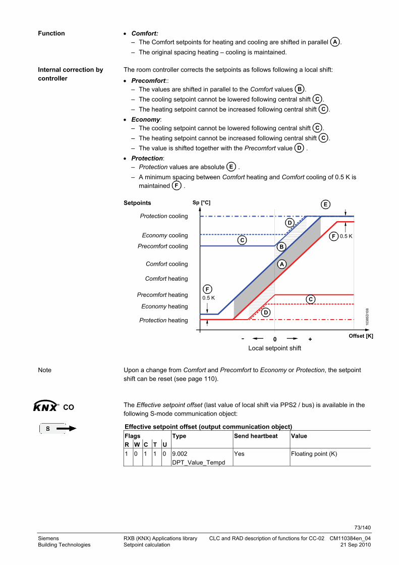
73/140
Siemens RXB (KNX) Applications library CLC and RAD description of functions for CC-02 CM110384en_04 Building Technologies Setpoint calculation 21 Sep 2010
Comfort: – The Comfort setpoints for heating and cooling are shifted in parallel A .
– The original spacing heating – cooling is maintained. The room controller corrects the setpoints as follows following a local shift:
Precomfort:: – The values are shifted in parallel to the Comfort values B .
– The cooling setpoint cannot be lowered following central shift C .
– The heating setpoint cannot be increased following central shift C .
Economy: – The cooling setpoint cannot be lowered following central shift C .
– The heating setpoint cannot be increased following central shift C .
– The value is shifted together with the Precomfort value D .
Protection: – Protection values are absolute E .
– A minimum spacing between Comfort heating and Comfort cooling of 0.5 K is maintained F .
Setpoints
Protection cooling
Economy cooling
Precomfort cooling
Comfort cooling
Comfort heating
Precomfort heating
Economy heating
Protection heating
103
85D
108
Sp [°C]
Offset [K]
A
0 +-
0.5 K
0.5 K
BC
D
F
E
C
D
F
Local setpoint shift
Upon a change from Comfort and Precomfort to Economy or Protection, the setpoint shift can be reset (see page 110). The Effective setpoint offset (last value of local shift via PPS2 / bus) is available in the following S-mode communication object:
Effective setpoint offset (output communication object)
Flags
R W C T U
Type Send heartbeat Value
1 0 1 1 0 9.002
DPT_Value_Tempd
Yes Floating point (K)
Function
Internal correction by controller
Note
KNXR
CO

74/140
Siemens RXB (KNX) Applications library CLC and RAD description of functions for CC-02 CM110384en_04 Building Technologies Temperature measurement 21 Sep 2010
7 Temperature measurement 7.1 Room temperature measurement
The value valid for temperature control can originate in various sources: – A room unit via PPS2 7.1.1 – An analog sensor via analog input B1 7.1.2 – Mean value of several sensors 7.1.3 – The bus. 7.1.6 If none of these sources supplies a valid room temperature, the following will happen: the controller uses the mean value from the effective heating and cooling setpoints
for control until a valid measured value is again received the controller issues an alarm "Room temp. sensor error" the bus output sends 0°C if slaves are connected, they receive an invalid temperatur (327.67°C) if a room unit is connected to a slave, the slave uses the temperature value of its
room unit when two heartbeat periods have elapsed.
7.1.1 Local temperature sensor at PPS2 interface
PPS2 (CP+, CP-)QAX3...
RXB2...
1038
5Z1
2
If a QAX… room unit (with PPS2 interface) is connected to the controller, the room temperature is measured by the temperature sensor integrated in the room unit.
7.1.2 Local temperature sensor at analog input
B1QAA24
RXB2...
1038
5Z1
3
Alternatively, an LG-Ni1000 sensor, type QAA24, can be connected to analog input B1 of the room controller.
The sensors connected to terminal B1 can have different functions:
Parameter setting Description
Room Room air sensor (can also be used for averaging together with room unit PPS; see below).
No sensor No sensor connected.
Only measured value acquisition
Uses the signal, see "analog input B1", page 112.
Sources
Invalid temperature

75/140
Siemens RXB (KNX) Applications library CLC and RAD description of functions for CC-02 CM110384en_04 Building Technologies Temperature measurement 21 Sep 2010
Select tab General functions, Temperature sensor B1 (see page 100).
Select General functions, Temperature sensor r B1 (see page 100).
HandyTool See the parameters in the last column of the following table.
Short name Basic setting Parameter
Temperature sensor B1 No sensor *092
Room 1 Only meas val acquisition 3 No sensor 255
Only meas val acquisition: Use of the signal: see "analog input B1", page 112.
7.1.3 Averaging analog input & PPS2 interface
In large spaces it can be useful to measure the room temperature in two locations and to determine an average value. If both a QAX3… room unit and a QAA24 LG-Ni1000 sensor are connected to a controller, the measured room temperature is automatically based on the average value from both sensors. Automatic detection prevents miscalculation. A QAX34 / QAX84 will display this average value.
PPS2 (CP+, CP-)B1
QAX3...
RXB2...
QAA24
1038
5Z1
4
The average value is calculated from the two sensor readings.
To determine the average value, the sensor must be configured as a room
temperature sensor There is no averaging in KNX sensors.
7.1.4 Sensor correction
The value of the local sensors (PPS2 and B1) can be corrected in the tools (see page 115).
ETS3 Professional
ACS Service
Notes

76/140
Siemens RXB (KNX) Applications library CLC and RAD description of functions for CC-02 CM110384en_04 Building Technologies Temperature measurement 21 Sep 2010
7.1.5 Temperature sensor outputs on the Konnex bus
To map the local temperature measurement in a building automation and control system, the following two output communication objects are used:
RXB... Room controller
10384Z15en
Effective room temperature
Room temperature output
R
O +
The value of the communication object Room temperature output is not filtered (not smoothed). Sending takes place only if room "Room" is parameterized for the temperature sensor B1.
The value transmitted as the Effective room Temperature is the filtered (smoothed) value of the communication object Room temperature output or Return air temperature output, or the average (see 7.1.3): Room temperature output (output communication object) Effective room temperature (output communication object)
Flags
R W C T U
Type Send heartbeat Value
1 0 1 1 0 9.001
DPT_Value_Temp
Yes Floating point (°C)
Invalid temperatures are mapped to the bus as 0 °C. In LTE mode, the room air temperature from directly connected sensors is mapped as follows:
Room temperature output (output)
Possible partner function
blocks) Known partner devices
TempRoom 390 UHD
UserHVACDisplay
Siemens:
Synco RMH760 / RMB795
RMU710 / 20 / 30
Geographical zone
Note
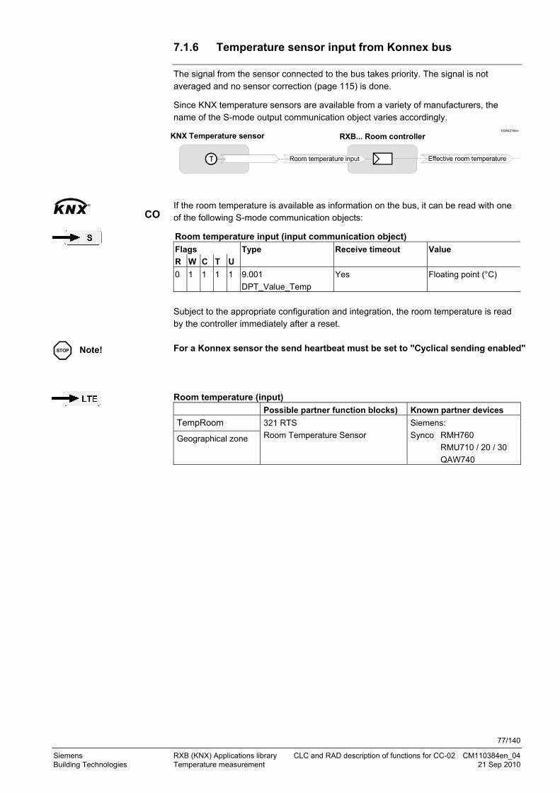
77/140
Siemens RXB (KNX) Applications library CLC and RAD description of functions for CC-02 CM110384en_04 Building Technologies Temperature measurement 21 Sep 2010
7.1.6 Temperature sensor input from Konnex bus
The signal from the sensor connected to the bus takes priority. The signal is not averaged and no sensor correction (page 115) is done.
Since KNX temperature sensors are available from a variety of manufacturers, the name of the S-mode output communication object varies accordingly.
RaumTemperatur EffektiveRaumTemperatur
10384Z16en
Room temperature input Effective room temperature
KNX Temperature sensor RXB... Room controller
If the room temperature is available as information on the bus, it can be read with one of the following S-mode communication objects:
Room temperature input (input communication object)
Flags
R W C T U
Type Receive timeout Value
0 1 1 1 1 9.001
DPT_Value_Temp
Yes Floating point (°C)
Subject to the appropriate configuration and integration, the room temperature is read by the controller immediately after a reset. For a Konnex sensor the send heartbeat must be set to "Cyclical sending enabled" Room temperature (input)
Possible partner function blocks) Known partner devices
TempRoom
Geographical zone
321 RTS
Room Temperature Sensor
Siemens:
Synco RMH760
RMU710 / 20 / 30
QAW740
KNXR
CO
STOP Note!

78/140
Siemens RXB (KNX) Applications library CLC and RAD description of functions for CC-02 CM110384en_04 Building Technologies Temperature measurement 21 Sep 2010
7.2 Outside air temperature via Konnex bus (CLC02, RAD01)
The outside air temperature must be provided as bus information to all applications with radiators. It can be read via the following S-mode communication object:
Outside temperature (input communication object)
Flags
R W C T U
Type Receive timeout Value
0 1 1 1 1 9.001
DPT_Value_Temp
Yes Floating point (°C)
Subject to the appropriate configuration and integration, the outside air temperature is read by the controller immediately after a reset.
In LTE mode, the outside temperature is sent in a zone intended specifically for that purpose. Outside temperature input (input)
Possible partner function blocks) Known partner devices
TempOutside
Outside temperature
zone
320 OTS
Room Temperature Sensor
Siemens:
Synco RMH760
RMU710 / 20 / 30
RMB795 / RMS705
KNXR
CO

79/140
Siemens RXB (KNX) Applications library CLC and RAD description of functions for CC-02 CM110384en_04 Building Technologies Control sequences 21 Sep 2010
8 Control sequences 8.1 Radiator (RAD01)
The radiator application has a continuous heating sequence. The room controllers operate with a PI algorithm optimized for thermal or motorized valve actuators. (For simplicity, the diagram below only shows the P-control action.)
This application can also be used for other heating types, e.g. floor heating. However, the control parameters are not optimized for this.
The control sequences come into operation at the effective setpoints for heating and cooling (see page 67).
100
0TR [°C]
Y [%]
SpH
YH
H
Y Output signal TR Room temperature SpH Effective heating setpoint H Heating sequence YH Heating valve
8.1.1 Actuator type selection
All actuators have threads suitable for fitting to both normally-closed (push to open) and normally-open (pull-to-open) valves. However, the RX applications do not support inverse control, which means that only actuators with a pulling action can be used with "pull-to-open" valves and only actuators with a pushing action can be used with "push-to-open" valves. This is why, in RX applications, valves with mounted actuators are always closed when de-energized. Different valve types are available for selection for the radiator:
– Thermal actuators are controlled by an AC 24 V PDM signal. – Motorized actuators are controlled by an AC 24 V 3- point signal. – Electromechanical actuators (motors with spring return) have a special PDM
algorithm that ensures that 50 position changes per day are not exceeded. This causes a slower control behavior.
Thermal and electromechanical actuators, therefore, require one output while motorized actuators require two. The table below shows the possible combinations:
Actuator type
Controller Outputs required
Thermal RXB24.1 Y1
Motorized RXB24.1 M
Y1
Y2
Electro-mechanic (ON / OFF)
RXB24.1 Y1 M
STOP Note!
Directly connected valve actuators

80/140
Siemens RXB (KNX) Applications library CLC and RAD description of functions for CC-02 CM110384en_04 Building Technologies Control sequences 21 Sep 2010
The RXB2… room controllers also support the use of motorized EIB/KNX bus actuators. In the tool, select Motoric bus. If thermal actuators are selected, Y1 / Y2 are always controlled in parallel to ensure
that several actuators can be connected at the same time. It is not possible to ensure exact parallel running of more than one thermal valve
actuator. If several radiators are controlled by the same room controller, preference should be given to motorized actuators. If thermal actuators must nevertheless be controlled in parallel, third-party thermal must be parameterized regardless of manufacture. This applies also if an external power amplifier is used to drive the actuators.
Thermal actuators operate at a raised temperature. To ensure a fast response, the actuators are continuously preheated to a slightly higher temperature (5% – 1 s ON / 19 s OFF). They therefore continue to receive pulses from the controller even when closed.
Möhlenhoff actuators have been tested successfully in our HVAC laboratory. Electromechanic third-party devices often have different runtimes for opening and closure. For optimal control, the longer of the two runtimes must thus be parameterized. When switching on the controller, after parameterization, after switching from test mode to normal mode and for valve protection (unblocking, see page 84), the actuators are synchronized:
Thermal heating and cooling valve actuators are controlled for 5 minutes with open (50% – 1 s ON/ 1 s OFF), then for 5 minutes with close" (5% – 1 s ON/ 19 s OFF).
Motorized actuators are opened first (110% runtime) and then closed (110% runtime).
The sequence starts after synchronization. The actuator type used must be defined at the engineering stage: Select Edit parameters, Sequences:
Motorized KNX/EIB bus actuators
Thermal valve actuators
Thermal third party devices
Electromechanic third-party devices
Synchronize
Parameterization
ETS3 Professional

81/140
Siemens RXB (KNX) Applications library CLC and RAD description of functions for CC-02 CM110384en_04 Building Technologies Control sequences 21 Sep 2010
Select the actuator type from the Sequences menu:
HandyTool Parameter Short name Basic setting
*063 Actuat h surf valve STA72E
Settings
STE71 1 SSA81 10 Motoric bus 250
STA71 3 SSB81 11 El’mech 3rd party devices
252
STP71 4 SQS81 12 Thermal 3rd party devices
253
STA72E 5 SSP81 14 Motoric 3rd party devices
254
STP72E 6
With motorized actuators (conventional and bus actuators), third-party devices can also be connected. The actuator running time can be adapted and an offset set accordingly. The offset considers the time between the electric pulse and the actual mechanic movement of the actuator. This is especially important for fast running actuators.
For electromechanic actuators, the actuator running time can be adapted.
For fast actuators, select valve type "Motoric 3rd party devices ".
ACS Service
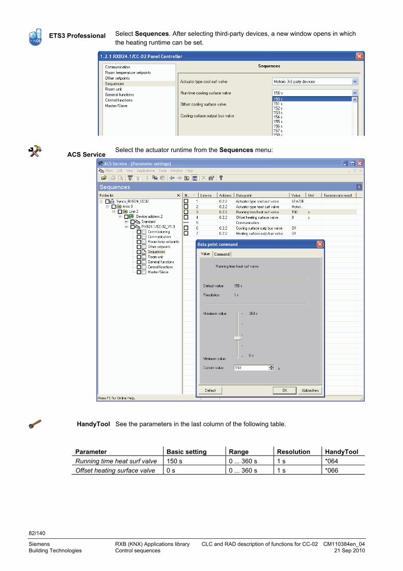
82/140
Siemens RXB (KNX) Applications library CLC and RAD description of functions for CC-02 CM110384en_04 Building Technologies Control sequences 21 Sep 2010
Select Sequences. After selecting third-party devices, a new window opens in which the heating runtime can be set.
Select the actuator runtime from the Sequences menu:
HandyTool See the parameters in the last column of the following table.
Parameter Basic setting Range Resolution HandyTool
Running time heat surf valve 150 s 0 ... 360 s 1 s *064
Offset heating surface valve 0 s 0 ... 360 s 1 s *066
ETS3 Professional
ACS Service

83/140
Siemens RXB (KNX) Applications library CLC and RAD description of functions for CC-02 CM110384en_04 Building Technologies Control sequences 21 Sep 2010
8.1.2 Values representing radiator valve actuator positions
The position of the radiator valve is mapped to the bus.
The Heating surface output communication object must NOT be used for applications for thermal valve actuators to control KNX/EIB valve actuators. With these applications, the communications objects have theoretical valve positions only. In S-mode, the following communication object is used for this purpose:
Heating surface output (output communication object)
Flags
R W C T U
Type Send heartbeat Value
1 0 1 1 0 5.001
DPT_scaling
Yes 0...100% 0 = 0%
255 = 100%
Since EIB/KNX bus actuators are available from a variety of manufacturers, the name of the S-mode output communication object varies accordingly. If KNX / EIB bus actuators (S-mode) are integrated in DESIGO, the flags must be checked: delete read access at actuator!
In LTE mode, the radiator position is transmitted as follows:
Heating surface output (output)
Possible partner function blocks) Known partner
devices
ActPosSetpHeatStageB
Geographical zone
352 HVA
HVAC Valve Actuator
---
In LTE-mode, where directly connected actuators are used rather than bus valve actuators, the bus load can be reduced by disabling LTE communication for these outputs (see also page 118). Select Sequences.
The two fields at the bottom appear only if "LTE and S-mode" is selected in the Communication menu.
STOP Important!
KNXR
CO
Note
Reduce bus load
ETS3 Professional
Note

84/140
Siemens RXB (KNX) Applications library CLC and RAD description of functions for CC-02 CM110384en_04 Building Technologies Control sequences 21 Sep 2010
Select Sequences.
HandyTool See the parameters in the last column of the following table.
Short name Range Basic setting HandyTool
Heat surf bus valve 0 = Disabled / Off, 1 = Enabled / On
Disabled (0) *086
8.1.3 Valve exercising feature
To prevent valves from seizing after long periods of inactivity (e.g. cooling valve in winter), the valves are operated from time to time. The valve actuators are operated in such a way as to waste as little heating or cooling energy as possible.
The valve exercising function is triggered if the valve has been closed for ca. 91 hours without interruption.
8.1.4 Override radiator valve actuators
For test purposes, the valve actuators can be overridden via the following communication object:
Heating surface valve override (input communication object)
Flags
R W C T U
Type Receive timeout Value
0 1 1 0 0 8.010
DPT_Percent_V16
No 0...100% 0 = 0%
+100 = +100%
+32767 = invalid
To override the radiator valve actuator, the test mode must be activated via the communication object Application mode (see page 105).
ACS Service
KNXR
CO
Note

85/140
Siemens RXB (KNX) Applications library CLC and RAD description of functions for CC-02 CM110384en_04 Building Technologies Control sequences 21 Sep 2010
8.1.5 Downdraft compensation
This function is only active in Comfort mode.
In situations where (owing to large internal heat gains) there is no heating demand from the room despite a low outdoor temperature (supplied via bus), large window surfaces can impair indoor comfort (through radiated cold, downward flow of cold air, condensation). A radiator located under the window can be used to slow the downward flow of cold air and compensate for cold radiation.
To achieve this, the radiator is switched on whenever the outdoor temperature drops below a predefined value (the outside temperature 0% valve position).
The maximum heating output (set under Max. valve position) is reached at the coldest outdoor temperature (which can be set under Max. outdoor temperature valve position).
25%
100%
0% TOA
Heating output
Outdoor temp.max. valve position
Max. valve position
103
85D
17en
_01
Outdoor temp.0% valve position
ThermicMotoric
The controller adds the values representing the valve position for downdraft compensation and the valve position for the heating sequence. – If the room temperature rises as a result of the downdraft compensation feature, the
heating sequence reduces the opening of the associated valve, so correcting the room temperature.
– When the sequence reaches zero, the room temperature is increased by the residual heat from the downdraft compensation feature.
The heat output calculated by the controller is achieved as follows:
LTHW radiators with motorized valve actuators
The valve is opened to the heat output value [%].
LTHW radiators with thermal valve actuators
The minimum heat output is 25% (LED08: 10%): 400 seconds "OPEN" (1s On, 1 s Off) 1200 s "CLOSE" (1s On, 19 s Off)
Heat output 50%: 400 seconds "OPEN" (1s On, 1 s Off) 400 s "CLOSE" (1s On, 19 s Off)
Heat output 80%: 1600 seconds "OPEN" (1s On, 1 s Off) 400 s "CLOSE" (1s On, 19 s Off)
The long cycle time ensures that the valves are fully opened and closed.
In a network containing several room controllers, the opening of the Siemens thermic actuators is staggered to prevent the heating load from fluctuating.
If a thermal radiator valve actuator and a thermal heating/cooling valve actuator work in parallel, the controller controls them alternately.
Function
Note
Controller output
Note

86/140
Siemens RXB (KNX) Applications library CLC and RAD description of functions for CC-02 CM110384en_04 Building Technologies Control sequences 21 Sep 2010
Select Sequences, Other setpoints:
Select Sequences, Other setpoints:
HandyTool See the parameters in the last column of the following table.
Parameter for downdraft compensation
Basic setting
Range
Resolution
Parameter HandyTool
Outside temp 0% valve pos 0 °C –30 … 10 °C 0.5 K *078
Outside temp max valve pos –10 °C –30 … 10 °C 0.5 K *079
Maximum valve pos 100% 0 ... 100% 1% *080
The following conditions must be fulfilled:
– The room controller must be in Comfort room operating mode.
ETS3 Professional
ACS Service
Enable the function

87/140
Siemens RXB (KNX) Applications library CLC and RAD description of functions for CC-02 CM110384en_04 Building Technologies Control sequences 21 Sep 2010
8.2 Chilled ceiling (CLC01)
The chilled ceiling application has a continuous cooling sequence. The room controllers operate with a PI algorithm optimized for thermal or motorized valve actuators. (For simplicity, the diagram below only shows the P-control action.)
The control sequence comes into operation at the effective setpoints for cooling (see page 67).
100
0TR [°C]
Y [%]
SpC
YC
C
Y Output signal TR Room temperature SpC Effective cooling setpoint C Cooling sequence YC Cooling valve
8.2.1 Select actuator types for chilled ceiling
See section 8.1.1, page 79 on selecting actuator types for radiators. The following information differs from the radiator applications:
HandyTool Parameter Short name Basic setting
*051 Actuat c’surf valve STA71
Settings
STE71 1 SSA81 10 Motoric bus 250
STA71 3 SSB81 11 El’mech 3rd party devices 252
STP71 4 SQS81 12 Thermal 3rd party devices 253
STA72E 5 SSC81 13 Motoric 3rd party devices 254
STP72E 6 SSP81 14
If thermal actuators are selected, Y3 / Y4 are always controlled in parallel to ensure
that several actuators can be connected at the same time. Exact parallel operation of several thermal valve actuators is not guaranteed. If
several radiators are controlled by the same controller, motorized actuators are the preferred device. If nevertheless thermal actuators are controlled in parallel, "3rd Party Thermic" must be parameterized regardless of make.
Thermal actuators work at higher temperatures. To ensure a fast reaction, the actuators are slightly preheated continuously (5% – 1 sec ON / 19 sec OFF). Then thus also receive pulses from the controller when closed.
Actuator type
Thermal valve actuators
Notes

88/140
Siemens RXB (KNX) Applications library CLC and RAD description of functions for CC-02 CM110384en_04 Building Technologies Control sequences 21 Sep 2010
Motorized and electromechanic valves
HandyTool
Parameter Basic setting Range Resolution HandyTool
Running time cool surf valve 150 s 0 ... 360 s 1 s *052
Offset cooling surface valve 0 s 0 ... 360 s 1 s *054
8.2.2 Values representing chilled ceiling valve actuator positions
The position of the chilled ceiling valve is mapped to the bus.
The Cooling surface output communication object must NOT be used for applications for thermal valve actuators to control KNX/EIB valve actuators. With these applications, the communications objects have theoretical valve positions only. Valve positions are available in the following S-mode communication objects:
Cooling surface output (output communication object)
Flags
R W C T U
Type Send heartbeat Value
1 0 1 1 0 5.001
DPT_Scaling
Yes 0...100% 0 = 0%
255 = 100%
If KNX / EIB bus actuators (S-mode) are integrated in DESIGO, the flags must be checked: delete read access at actuator!
As there are different manufacturers for EIB/KNX bus actuators, the name of the S-mode communication object varies. The valve position in LTE mode is transferred as follows:
Cooling surface output (output)
Possible partner function blocks Known partner
devices
ActPosSetpCoolStageA
Geographical zone
352 HVA
HVAC Valve Actuator
---
In LTE-mode, where directly connected actuators are used rather than bus valve actuators, the bus load can be reduced by disabling LTE communication for these outputs (see also pages 83 and 118).
STOP Important!
KNXR
CO
Note
Reduce bus load

89/140
Siemens RXB (KNX) Applications library CLC and RAD description of functions for CC-02 CM110384en_04 Building Technologies Control sequences 21 Sep 2010
Select Sequences.
The two fields at the bottom only are shown if "LTE and S-mode" are selected in the Communication menu. Select menu item Sequences:
HandyTool
Short name Range Basic setting HandyTool
Cool surf bus valve 0 = Disabled / Off, 1 = Enabled / On
disabled (0) *088
ETS3 Professional
Note
ACS Service
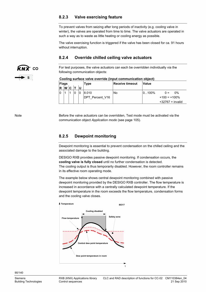
90/140
Siemens RXB (KNX) Applications library CLC and RAD description of functions for CC-02 CM110384en_04 Building Technologies Control sequences 21 Sep 2010
8.2.3 Valve exercising feature
To prevent valves from seizing after long periods of inactivity (e.g. cooling valve in winter), the valves are operated from time to time. The valve actuators are operated in such a way as to waste as little heating or cooling energy as possible.
The valve exercising function is triggered if the valve has been closed for ca. 91 hours without interruption.
8.2.4 Override chilled ceiling valve actuators
For test purposes, the valve actuators can each be overridden individually via the following communication objects:
Cooling surface valve override (input communication object)
Flags
R W C T U
Type Receive timeout Value
0 1 1 0 0 8.010
DPT_Percent_V16
No 0...100% 0 = 0%
+100 = +100%
+32767 = invalid
Before the valve actuators can be overridden, Test mode must be activated via the communication object Application mode (see page 105).
8.2.5 Dewpoint monitoring
Dewpoint monitoring is essential to prevent condensation on the chilled ceiling and the associated damage to the building.
DESIGO RXB provides passive dewpoint monitoring. If condensation occurs, the cooling valve is fully closed until no further condensation is detected. The cooling output is thus temporarily disabled. However, the room controller remains in its effective room operating mode.
The example below shows central dewpoint monitoring combined with passive dewpoint monitoring provided by the DESIGO RXB controller. The flow temperature is increased in accordance with a centrally calculated dewpoint temperature. If the dewpoint temperature in the room exceeds the flow temperature, condensation forms and the cooling valve closes.
Safety zoneFlow temperature
Central dew point temperature
Dew point temperature in room
t
Temperature
Cooling disabled
80317
KNXR
CO
Note
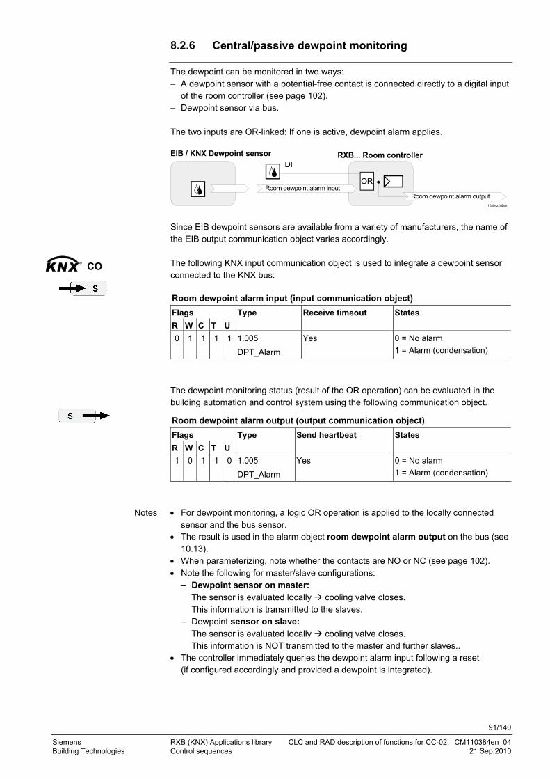
91/140
Siemens RXB (KNX) Applications library CLC and RAD description of functions for CC-02 CM110384en_04 Building Technologies Control sequences 21 Sep 2010
8.2.6 Central/passive dewpoint monitoring
The dewpoint can be monitored in two ways: – A dewpoint sensor with a potential-free contact is connected directly to a digital input
of the room controller (see page 102). – Dewpoint sensor via bus. The two inputs are OR-linked: If one is active, dewpoint alarm applies.
RXB... Room controller EIB / KNX Dewpoint sensor
10384z102en
Room dewpoint alarm input
DI
OR
Room dewpoint alarm output
Since EIB dewpoint sensors are available from a variety of manufacturers, the name of the EIB output communication object varies accordingly. The following KNX input communication object is used to integrate a dewpoint sensor connected to the KNX bus:
Room dewpoint alarm input (input communication object)
Flags
R W C T U
Type Receive timeout States
0 1 1 1 1 1.005
DPT_Alarm
Yes 0 = No alarm
1 = Alarm (condensation)
The dewpoint monitoring status (result of the OR operation) can be evaluated in the building automation and control system using the following communication object.
Room dewpoint alarm output (output communication object)
Flags
R W C T U
Type Send heartbeat States
1 0 1 1 0 1.005
DPT_Alarm
Yes 0 = No alarm
1 = Alarm (condensation)
For dewpoint monitoring, a logic OR operation is applied to the locally connected
sensor and the bus sensor. The result is used in the alarm object room dewpoint alarm output on the bus (see
10.13). When parameterizing, note whether the contacts are NO or NC (see page 102). Note the following for master/slave configurations:
– Dewpoint sensor on master: The sensor is evaluated locally cooling valve closes. This information is transmitted to the slaves.
– Dewpoint sensor on slave: The sensor is evaluated locally cooling valve closes. This information is NOT transmitted to the master and further slaves..
The controller immediately queries the dewpoint alarm input following a reset (if configured accordingly and provided a dewpoint is integrated).
KNXR
CO
Notes
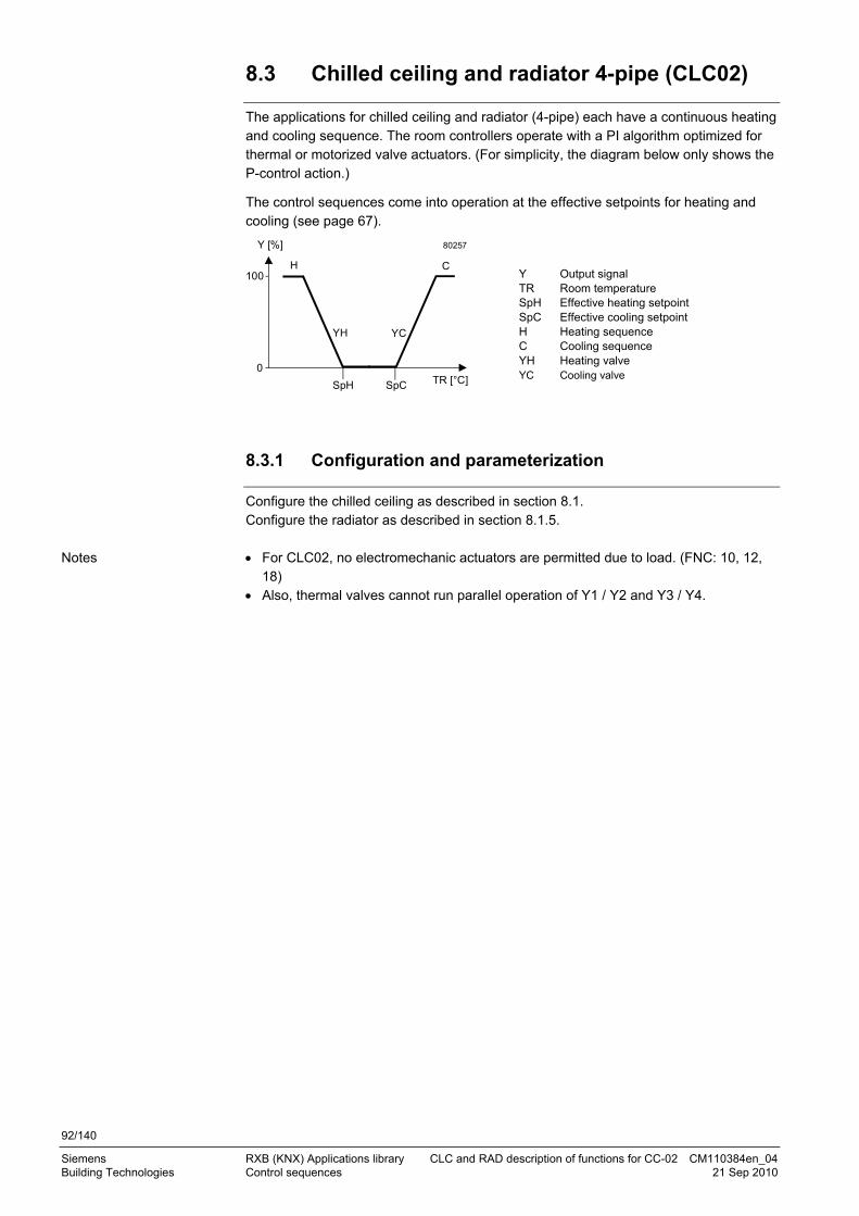
92/140
Siemens RXB (KNX) Applications library CLC and RAD description of functions for CC-02 CM110384en_04 Building Technologies Control sequences 21 Sep 2010
8.3 Chilled ceiling and radiator 4-pipe (CLC02)
The applications for chilled ceiling and radiator (4-pipe) each have a continuous heating and cooling sequence. The room controllers operate with a PI algorithm optimized for thermal or motorized valve actuators. (For simplicity, the diagram below only shows the P-control action.)
The control sequences come into operation at the effective setpoints for heating and cooling (see page 67).
100
0TR [°C]
Y [%]
SpH SpC
YCYH
H C
80257
Y Output signal TR Room temperature SpH Effective heating setpoint SpC Effective cooling setpoint H Heating sequence C Cooling sequence YH Heating valve YC Cooling valve
8.3.1 Configuration and parameterization
Configure the chilled ceiling as described in section 8.1. Configure the radiator as described in section 8.1.5. For CLC02, no electromechanic actuators are permitted due to load. (FNC: 10, 12,
18) Also, thermal valves cannot run parallel operation of Y1 / Y2 and Y3 / Y4.
Notes
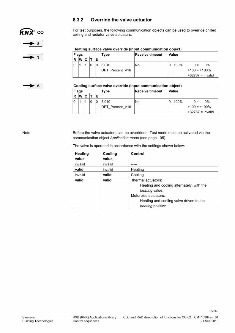
93/140
Siemens RXB (KNX) Applications library CLC and RAD description of functions for CC-02 CM110384en_04 Building Technologies Control sequences 21 Sep 2010
8.3.2 Override the valve actuator
For test purposes, the following communication objects can be used to override chilled ceiling and radiator valve actuators. Heating surface valve override (input communication object)
Flags
R W C T U
Type Receive timeout Value
0 1 1 0 0 8.010
DPT_Percent_V16
No 0...100% 0 = 0%
+100 = +100%
+32767 = invalid
Cooling surface valve override (input communication object)
Flags
R W C T U
Type Receive timeout Value
0 1 1 0 0 8.010
DPT_Percent_V16
No 0...100% 0 = 0%
+100 = +100%
+32767 = invalid
Before the valve actuators can be overridden, Test mode must be activated via the communication object Application mode (see page 105).
The valve is operated in accordance with the settings shown below:
Heating value
Cooling value
Control
invalid invalid -----
valid invalid Heating
invalid valid Cooling
valid valid thermal actuators: Heating and cooling alternately, with the heating value.
Motorized actuators: Heating and cooling valve driven to the heating position.
KNXR
CO
Note
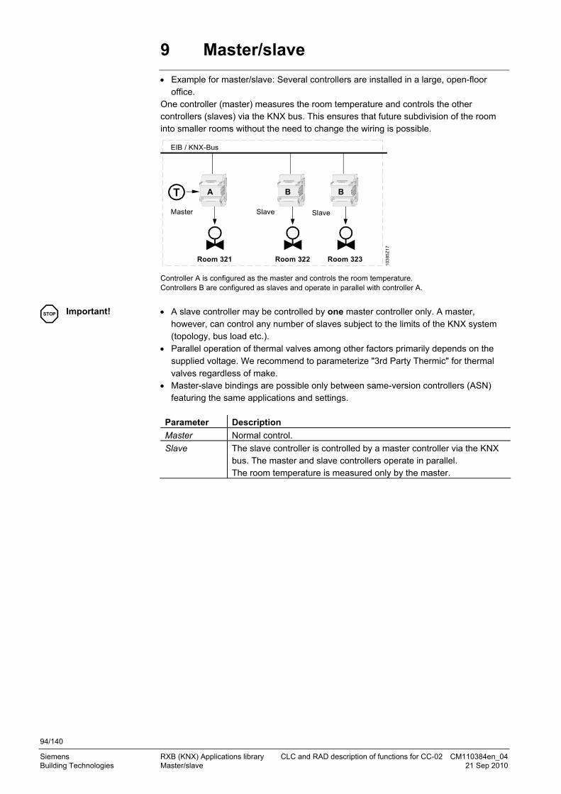
94/140
Siemens RXB (KNX) Applications library CLC and RAD description of functions for CC-02 CM110384en_04 Building Technologies Master/slave 21 Sep 2010
9 Master/slave
Example for master/slave: Several controllers are installed in a large, open-floor office.
One controller (master) measures the room temperature and controls the other controllers (slaves) via the KNX bus. This ensures that future subdivision of the room into smaller rooms without the need to change the wiring is possible.
BAT B
EIB / KNX-Bus
103
85Z
17
Master Slave Slave
Room 321 Room 322 Room 323
Controller A is configured as the master and controls the room temperature. Controllers B are configured as slaves and operate in parallel with controller A.
A slave controller may be controlled by one master controller only. A master,
however, can control any number of slaves subject to the limits of the KNX system (topology, bus load etc.).
Parallel operation of thermal valves among other factors primarily depends on the supplied voltage. We recommend to parameterize "3rd Party Thermic" for thermal valves regardless of make.
Master-slave bindings are possible only between same-version controllers (ASN) featuring the same applications and settings.
Parameter Description
Master Normal control.
Slave The slave controller is controlled by a master controller via the KNX bus. The master and slave controllers operate in parallel. The room temperature is measured only by the master.
STOP Important!

95/140
Siemens RXB (KNX) Applications library CLC and RAD description of functions for CC-02 CM110384en_04 Building Technologies Master/slave 21 Sep 2010
9.1 S-mode
Master
Slave 1
Slave 2
Slave n
GA1
GA3
GA2
GA4
M/S HVAC controller input
M/S Room unit input
M/S HVAC controller output
M/S Room unit output
103
85Z
18e
n
M/S HVAC controller input
M/S Room unit input
M/S HVAC controller input
M/S Room unit input
M/S HVAC controller input
M/S Room unit input
M/S HVAC controller output
M/S Room unit output
M/S HVAC controller output
M/S Room unit output
M/S HVAC controller output
M/S Room unit output
The following S-mode input and output communication objects are used for master/slave connection:
Master/slave HVAC controller output (output comm'object) (company-specific)
Master/slave room unit output (output comm'object) (company-specific)
Master/slave HVAC controller input (input comm'object) (company-specific)
Master/slave room unit input (input comm'object) (company-specific)
You need 4 group addresses (GA1 … GA4) regardless of the number of slaves.
Select Master/Slave:
KNXR
CO
Note
ETS3 Professional

96/140
Siemens RXB (KNX) Applications library CLC and RAD description of functions for CC-02 CM110384en_04 Building Technologies Master/slave 21 Sep 2010
9.1.1 Window switch (S-Mode)
For master/slave mode, only the master's window switch is evaluated without special measures, which also influences the slave controllers.
If another window switch is also connected to the slave, it is NOT considered unless you create the following binding:
Master Slave
10385Z118en
DI DI
Window contact Input Window contact Output
This binding ensures that both controllers react when a window is opened. If several slaves are equipped with window switches, the correct evaluation is required for the logic block.
9.1.2 Presence detector (S-mode)
For master/slave mode, only the master's presence detector is evaluated without special measures, which also influences the slave controllers.
If another presence detector is also connected to the slave, it is NOT considered unless you create the following binding:
Master Slave
10385Z119en
DI DI
Presence detector Input Presence detector Output
This binding ensures that both controllers react when a presence detector becomes active. If several slaves are equipped with presence detectors, the correct evaluation is required for the logic block.
9.1.3 Dewpoint sensor (S-mode)
For master/slave mode, only the master's dewpoint sensor is evaluated without special measures, which also influences the slave controllers.
If another dewpoint sensor is also connected to the slave, it is NOT considered unless you create the following binding:
Master Slave
10385Z120en
DI DI
Dew point sensor Input Dew point sensor Output
This binding ensures that both controllers react when a dewpoint sensor becomes active. If several slaves are equipped with dewpoint sensors, the correct evaluation is required for the logic block.

97/140
Siemens RXB (KNX) Applications library CLC and RAD description of functions for CC-02 CM110384en_04 Building Technologies Master/slave 21 Sep 2010
9.2 LTE mode with zones
The master/slave configuration is also possible in LTE mode. However, you are not required to create the individual connections but define the master/slave zone.
Here too: The slave can be controlled only by one master, and master/slave bindings are possible only between same-version controllers (ASN) featuring the same applications and settings.
Select Master/Slave:
M S S Room 321 322 323
Geogr. zone 5.1.1 5.2.1 5.3.1
Master/slave Master Slave Slave
M/S zone 5.1.1 5.1.1 5.1.1
Geogr. zone and M/S zone do not necessarily need to match. In reality, however, it makes sense as seeing which slave belongs to which master is obvious immediately. Select Master/Slave:
ETS3 Professional
Example
Note
ACS Service

98/140
Siemens RXB (KNX) Applications library CLC and RAD description of functions for CC-02 CM110384en_04 Building Technologies Master/slave 21 Sep 2010
The M/S function presupposes that all 3 M/S zones match. If the master/slave function is not required, the M/S zone should be disabled (to limit
the load on the bus).
HandyTool Parameter Short name Basic setting
*021 Master/Slave Master
*022 M/S zone (apartm) 1
*023 M/S zone (room) –1 (out of service)
*024 M/S zone (subzone) 1
Parameter Setting HandyTool
*021 Master/Slave Master 1
Slave 0
9.2.1 Window switch (LTE mode)
For master/slave mode, only the master's window switch is evaluated without special measures, which also influences the slave controllers.
Window switches on the slaves are NOT considered.
9.2.2 Presence detector (LTE mode)
For master/slave mode, only the master's presence detector is evaluated without special measures, which also influences the slave controllers.
Presence detectors on the slaves are NOT considered.
9.2.3 Dewpoint sensor (LTE mode)
For master/slave mode, only the master's presence detector is evaluated without special measures, which also influences the slave controllers.
Window switches on the slaves are NOT considered.
Notes
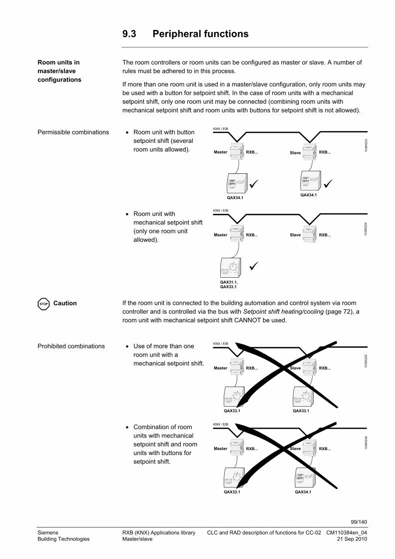
99/140
Siemens RXB (KNX) Applications library CLC and RAD description of functions for CC-02 CM110384en_04 Building Technologies Master/slave 21 Sep 2010
9.3 Peripheral functions
The room controllers or room units can be configured as master or slave. A number of rules must be adhered to in this process.
If more than one room unit is used in a master/slave configuration, only room units may be used with a button for setpoint shift. In the case of room units with a mechanical setpoint shift, only one room unit may be connected (combining room units with mechanical setpoint shift and room units with buttons for setpoint shift is not allowed).
Room unit with button
setpoint shift (several room units allowed). RXB... RXB... 1
038
5Z
23
QAX34.1
Master Slave
KNX / EIB
QAX34.1
Room unit with mechanical setpoint shift (only one room unit allowed).
QAX31.1,QAX33.1
RXB... RXB...Master Slave
KNX / EIB
10
385
Z24
- +
Auto
If the room unit is connected to the building automation and control system via room controller and is controlled via the bus with Setpoint shift heating/cooling (page 72), a room unit with mechanical setpoint shift CANNOT be used. Use of more than one
room unit with a mechanical setpoint shift.
RXB... RXB...
- +
Auto
QAX33.1
Master Slave
KNX / EIB
- +
Auto
QAX33.1
10
385
Z25
Combination of room units with mechanical setpoint shift and room units with buttons for setpoint shift.
RXB... RXB...
- +
Auto
QAX33.1
Master Slave
KNX / EIB
QAX34.1
10
385
Z26
Room units in master/slave configurations
Permissible combinations
STOP Caution
Prohibited combinations

100/140
Siemens RXB (KNX) Applications library CLC and RAD description of functions for CC-02 CM110384en_04 Building Technologies General / central functions 21 Sep 2010
10 General / central functions
The following functions are enabled or configured via Edit parameters, Communication or General functions or Central functions.
ETS3 Professional
See Section
3
10.1
10.6 10.8
10.14
10.2 7.1.2 10.3 10.4

101/140
Siemens RXB (KNX) Applications library CLC and RAD description of functions for CC-02 CM110384en_04 Building Technologies General / central functions 21 Sep 2010
The following functions are enabled or configured under General functions or Central functions.
*) Room number and Device name do not influence the application; they are used only
for plant documentation purposes. We recommend to use this feature.
HandyTool General and central functions are set using parameters 117 – 137 (see the individual sections for detailed information).
ACS Service
10.2
7.1.2 10.3 10.4
*)
10.14

102/140
Siemens RXB (KNX) Applications library CLC and RAD description of functions for CC-02 CM110384en_04 Building Technologies General / central functions 21 Sep 2010
10.1 Send heartbeat and Receive timeout
In a KNX network, S-mode and LTE mode communication objects can be exchanged between individual devices. The receive timeout defines the period of time within which all communication objects of a device must be received at least once. If a communication object is not received within this period, a predefined value is used and an error message generated. This ensures that interruptions in communication are identified at an early stage.
Similarly, send heartbeat defines the period of time within which all requested communication objects must be transmitted at least once.
The time intervals are based on the size of the network. Normally the basic setting can be retained. In the case of S-mode communication objects, shorter times may be selected for smaller networks or for test purposes. The receive timeout must always be longer than the send heartbeat. Parameter Basic setting Range Resolution
Receive timeout 60 min 0 ... 105 min 5 min
Send heartbeat 45 min 0 ... 105 min 5 min
(0 = not enabled) Fixed times are specified as follows:
Receive timeout: 31 min
Send heartbeat: 15 min
HandyTool Parameter Short name Basic setting
*128 Receive timeout 60 min
*127 Send heartbeat 45 min
10.2 Digital inputs
The following potential-free contacts can be connected to digital inputs D1 and D2:
Presence detector or window contact (see section 5). Dewpoint sensor (see section 8.2.5).
Digital input Function Contact action HandyTool
Input 1 Input 2
*113 *114
Not used by the application
Free: Bus = 1 = Contact closed Free: Bus = 1 = Contact open
0 = Default1
(Free input, contact can be used freely (see page 111).
Occupancy Occupied = Contact closed Occupied = Contact open
23
Window Window open = Contact open Window open = Contact closed
45
Dewpoint Dewpoint = Contact closed Dewpoint = Contact open
89
Do not connect the same type of sensor / functions to both digital inputs. The controller would ignore the second input.
S-Mode
LTE and S-mode
Note

103/140
Siemens RXB (KNX) Applications library CLC and RAD description of functions for CC-02 CM110384en_04 Building Technologies General / central functions 21 Sep 2010
10.3 Temporary Comfort mode
If the room controller is set to Economy and the associated room unit is switched to Auto (Comfort), the room controller maintains Comfort for the period defined by the temporary comfort mode time and then returns to Economy. This function is only available if the room unit concerned has an Auto button (see also pages 40 and 51).
Parameter
Basic setting
Range
Resolution
HandyTool
Temporary Comfort mode 60 min 0 ... 360 min 1 min *117
10.4 Presence detector switch-on and switch-off delay
A switch-on or switch-off delay can be applied to the presence detector function. The room controller only switches to Comfort (or to Precomfort or Economy) after the delay time is expired.
Parameter
Basic setting
Range
Resolution
HandyTool
On-delay occupancy sensor 5 min 0 ... 90 min 1 min *119
Off-delay occupancy sensor 5 min 0 ... 90 min 1 min *120
10.5 Heating and cooling demand
To provide the required heating or cooling energy, the heating and/or cooling demand from each room is transmitted to the building automation and control system.
For a more in-depth understanding of heating and cooling demand, see the application example in section 3.4. The function can be disabled in the room controller with ETS. The parameter is not available.
HandyTool See the parameter in the last column of the following table.
Parameter Description HandyTool
Heat demand signal Heating demand transmitted to the BAC system. *131
Cooling demand signal
Cooling demand transmitted to the BAC system. *132
Parameter Range Basic setting
*131, *132 0 = Disabled/ Off 1 = Enabled / On
0 = Disabled
ETS3 Professional
ACS Service

104/140
Siemens RXB (KNX) Applications library CLC and RAD description of functions for CC-02 CM110384en_04 Building Technologies General / central functions 21 Sep 2010
The heating or cooling demand can be evaluated via the S-mode communication object.
Energy demand room (output communication object)
Flags
R W C T U
Type Send heartbeat Value
1 0 1 1 0 6.001
DPT_Percent_V8
Yes –100...100% : (-128 ... +127)
–100% = Full heating
+100% = Full cooling
In LTE mode, the energy demand is determined by two signals:
Heat demand heating surface (output)
Possible partner function blocks Known partner devices
EnergyDemRD
Distribution zone,
heating
153 RHDTTU
Radiator Energy Demand
Transformer TU
Siemens:
Synco RMH760
RMU710 / 20 / 30
RMB795 / RMS705
Refrigeration demand cooling surface (output)
Possible partner function blocks Known partner devices
EnergyDemCC
Distribution zone,
cooling
216 CCDTTU
Chilled Ceiling Energy Demand
Transformer TU
Siemens:
Synco RMU710 / 20 / 30
RMB795 / RMS705
10.6 Heating/cooling signal output
The heating/cooling state display is mapped to a building automation and control system via the following S-mode communication object (states 1, 3, 20):
Effective application mode (output communication object)
Flags
R W C T U
Type Send heartbeat States
1 0 1 1 0 20.105
DPT_HVACContrMode
Yes 1 = Heat 3 = Cool 20 = No demand
KNXR
CO
KNXR
CO

105/140
Siemens RXB (KNX) Applications library CLC and RAD description of functions for CC-02 CM110384en_04 Building Technologies General / central functions 21 Sep 2010
10.7 Special functions
The functions described in sections 10.8 and following are initiated via the following S-mode communication object:
Application mode (input communication object)
Flags
R W C T U
Type Receive timeout States
0 1 1 0 0 20.105
DPT_HVACContrMode
Yes 0 = Auto 1 = Heat 2 = Morning Warmup 3 = Cool 5 = Precool 6 = Off 7 = Test *) 8 = Emergency Heat 10 = Freecool Übrige Zustände nicht benutzt
*) Exit from Test (7) is only possible with the sequence Off (6) + normal mode (0).
The following communication object is used in LTE mode:
Application mode (input)
Possible partner function blocks Known partner devices
ContrMode
Time switch
zone
104 PMC Programs to HVAC-Mode Conversion 109 BOS Building/Occ-Mode Source 115 HVACOPT HVAC Optimizer
Siemens:
Synco RMB795
State Description see section
Para-meter
0 = Auto Controller operating normally. 1 = Heat Controller can heat only; cooling sequence is
disabled.
2 = Morning Warmup Boost heating. 10.8 *134 3 = Cool Controller can cool only; heating sequence is
disabled.
5 = Precool
Precooling: Use chilled ceiling to precool the room.
10.9 *135
6 = Off Temperature control is disabled. The remaining functions are active. Communication is operating as normal.
--
7 = Test *) All functions disabled. Motorized valve and damper actuators synchronized. Outputs can be overridden via KNX bus.
10.10
8 = Emergency Heat Emergency heating. 10.11 10 = Freecool
Free cooling
During Economy, precool the room using chilled ceiling (low tariff energy).
During Comfort normal mode.
10.12 *135
*) Exit from Test (7) is only possible with the sequence Off (6) + normal mode (0).
KNXR
CO
Meaning of the states

106/140
Siemens RXB (KNX) Applications library CLC and RAD description of functions for CC-02 CM110384en_04 Building Technologies General / central functions 21 Sep 2010
Triggering the special functions by the building automation and control system can be disabled in each room controller via tool.
ETS3 Professional Go to the Functions menu for the disable feature.
HandyTool See parameters in the last column of the above table.
10.8 Morning boost (Morning Warmup, 2)
This function is used to raise the temperature in a room as quickly as possible to the Precomfort heating setpoint at the end of the night setback period.
Objective: Preheat the room in the event of heating.
100
0TR
103
84D
23
Y [%]
SpHStby SpCStby
The following conditions must be fulfilled: The room controller must be in Economy room operating mode.
The function can be disabled in the room controller with ETS3. The function must be enabled via the building automation and control system (communication object Application mode, see page 105). The function is disabled via the building automation and control system.
10.9 Precooling (Precool, 5)
This function is used to cool rooms to the Comfort cooling setpoint prior to actual occupancy.
100
TR
103
84D
25
0
Y [%]
SpHCmf SpCCmf
Disable special functions
Enable function
Start function
Terminate function

107/140
Siemens RXB (KNX) Applications library CLC and RAD description of functions for CC-02 CM110384en_04 Building Technologies General / central functions 21 Sep 2010
The following condition must be fulfilled:
The room controller must be in Economy or Precomfort room operating mode.
The function can be disabled in the room controller via ETS3, together with free cooling; see central functions on page 100. The function must be enabled via the building automation and control system (communication object Application mode, see page 105). The function is disabled via the building automation and control system.
10.10 Test mode (Test, 7)
The following override functions are used to commission the controller and for service purposes, e.g. to test a valve actuator. The controller must first be switched to HVAC test mode by transmitting the value 7 =TEST via Application mode. To exit test mode, send first Application mode = 6, OFF and then = 0, AUTO. In test mode, valve actuators can be se to defined values via KNX bus signals. A soft reset is carried out after the controller exits test mode:
Motorized valve actuators and dampers are synchronized. Thermal valves are synchronized. The control algorithm but not the entire application is restarted. Test mode is available only for S-mode objects!
10.11 Emergency heat (8)
This function is used for emergency heating when the room temperature drops below the Risk of frost limit value. The function depends on the Effective room operating mode.
The function affects control of all installed heating aggregates.
When using a radiator and a heated ceiling the valve opens fully. An electric radiator is switched to the highest stage and is maintained there until the temperature rises above the Protection heating setpoint again.
When the room temperature rises above the Protection setpoint, the controller reverts to the original application mode (see page 105).
Enable function
Start function
Terminate function
Test mode
Aggregates
Soft reset
Restrictions

108/140
Siemens RXB (KNX) Applications library CLC and RAD description of functions for CC-02 CM110384en_04 Building Technologies General / central functions 21 Sep 2010
Normal operationTR
10
38
5D
26
SpFr SpHPrt
Emergency Heat
The following condition must be fulfilled:
– The building temperature must be below the Risk of frost limit.
The function CANNOT be disabled in the room controller with ETS3. The function must be enabled via the building automation and control system (communication object Application mode, see page 105). – The function is disabled via the building automation and control system. – When the room temperature rises above the Protection setpoint.
10.12 Free cooling (Freecool, 10)
This function is used to cool rooms to the Comfort cooling setpoint prior to actual occupancy. The chilled ceiling is used actively. This is meaningful, however, only if cheap low-tariff energy is available.
During occupancy (room operating modes Comfort / Precomfort) normal mode applies.
100
TR
10
38
4D28
0
Y [%]
SpHCmf SpCCmf
The function can be disabled in the room controller via ETS3, together with precooling; see central functions on page 100. The function must be enabled via the building automation and control system (communication object Application mode, see page 105). The function is disabled via the building automation and control system.
Enable function
Start function
Terminate function
Enable function
Start function
Terminate function

109/140
Siemens RXB (KNX) Applications library CLC and RAD description of functions for CC-02 CM110384en_04 Building Technologies General / central functions 21 Sep 2010
10.13 Alarm
Alarming works differently in S-mode and LTE mode.
RXB controller support different alarms:
PPS2 fault If the connection to the room unit is faulty at the room controller (via PPS2 interface), the information is transmitted with this alarm message.
Room temp. sensor error
Sensor interruption or short. No valid room temperature.
Room air condensation Risk of condensation if temperature drops below dewpoint temperature.
10.13.1 S-mode
In S-mode, the above alarms are summarized and provided as common alarm.
The alarm message is mapped to the following S-mode output communication object:
Common alarm (output communication object)
Flags
R W C T U
Type Send heartbeat States
1 0 1 1 0 1.005
DPT_Alarm
Yes 0 = No alarm
1 = Alarm As soon as the cause of the alarm ceases to exist, the alarm message disappears. In addition, the output Alarm info provides detailed information:
Alarm info (output communication object)
Flags
R W C T U
Type Send heartbeat Info
1 0 1 1 0 219.001
DPT_AlarmInfo
Yes See Konnex specification
The Alarm info output can be enabled or disabled via another communication object (this also affects the LTE mode fault signal):
Enable alarm info (input communication object)
Flags
R W C T U
Type Receive timeout States
0 1 1 0 0 1.003
DPT_Enable
Yes (fixed 42 hours) 0 = Disabled / Off
1 = Enabled / On
KNXR
CO
Note
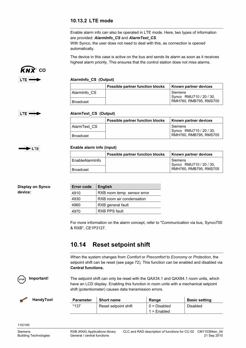
110/140
Siemens RXB (KNX) Applications library CLC and RAD description of functions for CC-02 CM110384en_04 Building Technologies General / central functions 21 Sep 2010
10.13.2 LTE mode
Enable alarm info can also be operated in LTE mode. Here, two types of information are provided: AlarmInfo_CS and AlarmText_CS. With Synco, the user does not need to deal with this, as connection is opened automatically.
The device in this case is active on the bus and sends its alarm as soon as it receives highest alarm priority. This ensures that the control station does not miss alarms.
AlarmInfo_CS (Output)
Possible partner function blocks Known partner devices
AlarmInfo_CS
Broadcast
Siemens Synco RMU710 / 20 / 30, RMH760, RMB795, RMS705
AlarmText_CS (Output)
Possible partner function blocks Known partner devices
AlarmText_CS
Broadcast
Siemens Synco RMU710 / 20 / 30, RMH760, RMB795, RMS705
Enable alarm info (input)
Possible partner function blocks Known partner devices
EnableAlarmInfo
Broadcast
Siemens Synco RMU710 / 20 / 30, RMH760, RMB795, RMS705
Error code English
4910 RXB room temp. sensor error
4930 RXB room air condensation
4960 RXB general fault
4970 RXB PPS fault
For more information on the alarm concept, refer to "Communication via bus, Synco700 & RXB", CE1P3127.
10.14 Reset setpoint shift
When the system changes from Comfort or Precomfort to Economy or Protection, the setpoint shift can be reset (see page 72). This function can be enabled and disabled via Central functions. The setpoint shift can only be reset with the QAX34.1 and QAX84.1 room units, which have an LCD display. Enabling this function in room units with a mechanical setpoint shift (potentiometer) causes data transmission errors.
HandyTool Parameter Short name Range Basic setting
*137 Reset setpoint shift 0 = Disabled 1 = Enabled
Disabled
KNXR
CO
Display on Synco device:
STOP Important!

111/140
Siemens RXB (KNX) Applications library CLC and RAD description of functions for CC-02 CM110384en_04 Building Technologies General / central functions 21 Sep 2010
10.15 Free inputs/outputs
In a building automation and control system, the free I/Os can be used to e.g. query switching states or for direct switch control of another device over the network. However, these functions are not suitable for time-critical processes (<1 s).
Free inputs can be defined as NC or NO (see 10.2).
If not already in use, the following inputs and outputs can be used freely:
RXB24.1/CC-02 Appli-cation
Digital inputs
Triac outputs
D1 D2 Y1 Y2 Y3 Y4
CLC01 1 2
CLC02 3 4
RAD01 5 6
Digital inputs 7 If "Not used" (see page 102), can be used freely.
Triac outputs X Used by the application. Can be used freely.
Only freely usable with bus valve actuators. (All combinations: see CM110671).
Parameter setting for free inputs see 10.2, page 102.
10.15.1 Digital inputs on the KNX bus
D1
D2
RXB... Room controller
Digital input 1
Digital input 2
10385Z19en
The following S-mode input and output communication objects are used when taking advantage of spare inputs and outputs:
Digital input 1 (output communication object) Digital input 2 (output communication object)
Flags
R W C T U
Type Send heartbeat States
1 0 1 1 0 1.001 DPT_Switch
No 0 (see 10.2) 1
Parameter setting in tool Cause: digital input Effect: bus output
Free: Bus = 1 = Contact closed Contact closed 1
Contact open 0
Free: Bus = 1 = Contact open Contact open 1
Contact closed 0
Key
KNXR
CO

112/140
Siemens RXB (KNX) Applications library CLC and RAD description of functions for CC-02 CM110384en_04 Building Technologies General / central functions 21 Sep 2010
10.15.2 KNX signals on digital/analog outputs
Y1
RXB... Room controller
Triac Y1
10384Z22en
Triac Y1 (input communication object) Triac Y2 (input communication object) Triac Y3 (input communication object) Triac Y4 (input communication object)
Flags
R W C T U
Type Receive timeout States
0 1 1 0 0 1.001 DPT_Switch
No 0 = Off (no voltage) 1 = On (AC 24V)
10.15.3 Mapping the sensor B1 to the Konnex bus
B1
RXB... Room controller
Analog input B1
10385Z201en
Sensor B1 can be set on the bus in S-mode as universal temperature (e.g. outside temperature). To do this, the temperature sensor must be parameterized as "measurement only“ (see page 74.)
Analog input B1 (output communication object)
Flags
R W C T U
Type Send heartbeat States
1 0 1 1 0 9.001 DPT_Value_Temp
Yes
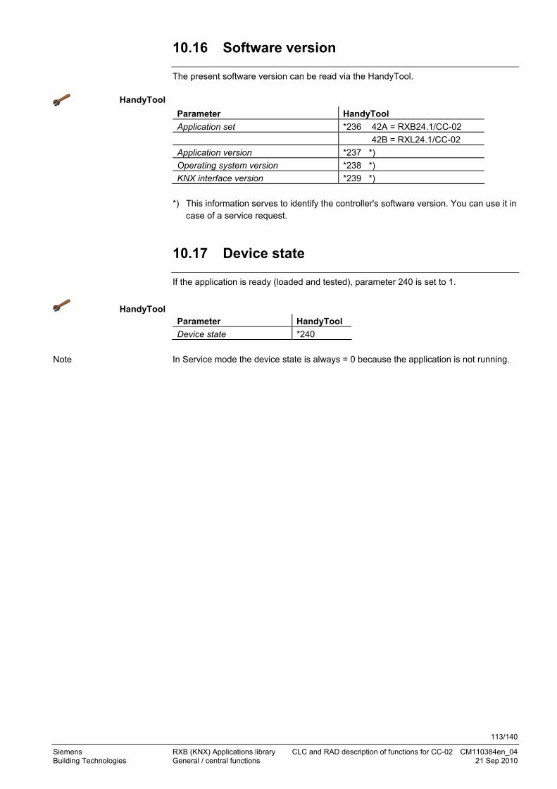
113/140
Siemens RXB (KNX) Applications library CLC and RAD description of functions for CC-02 CM110384en_04 Building Technologies General / central functions 21 Sep 2010
10.16 Software version
The present software version can be read via the HandyTool.
HandyTool
Parameter HandyTool
Application set *236 42A = RXB24.1/CC-02
42B = RXL24.1/CC-02
Application version *237 *)
Operating system version *238 *)
KNX interface version *239 *)
*) This information serves to identify the controller's software version. You can use it in
case of a service request.
10.17 Device state
If the application is ready (loaded and tested), parameter 240 is set to 1.
HandyTool Parameter HandyTool
Device state *240
In Service mode the device state is always = 0 because the application is not running.
Note

114/140
Siemens RXB (KNX) Applications library CLC and RAD description of functions for CC-02 CM110384en_04 Building Technologies Room unit 21 Sep 2010
11 Room unit
Select Room unit:
Select Room unit:
HandyTool See the parameters in the last column of the following table.
Designation Basic setting HandyTool
Measured value correction 0.0 K *101
Setpoint offset range ± 3 K *103
Local Comfort mode Enabled *105
Room unit (fixed for HandyTool "With LCD") Without LCD --
Temperature unit (only room units with LCD) Degrees Celsius *108
Standard display (only room units with LCD) Room temperature *109
Setpoint display (only room units with LCD) Relative *110
ETS3 Professional
ACS Service
Parameter
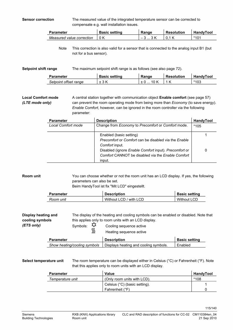
115/140
Siemens RXB (KNX) Applications library CLC and RAD description of functions for CC-02 CM110384en_04 Building Technologies Room unit 21 Sep 2010
The measured value of the integrated temperature sensor can be corrected to compensate e.g. wall installation issues.
Parameter Basic setting Range Resolution HandyTool
Measured value correction 0 K – 3 ... 3 K 0,1 K *101
This correction is also valid for a sensor that is connected to the analog input B1 (but not for a bus sensor). The maximum setpoint shift range is as follows (see also page 72).
Parameter Basic setting Range Resolution HandyTool
Setpoint offset range ± 3 K ± 0 ... 10 K 1 K *103
A central station together with communication object Enable comfort (see page 57) can prevent the room operating mode from being more than Economy (to save energy). Enable Comfort, however, can be ignored in the room controller via the following parameter:
Parameter Description HandyTool Local Comfort mode
Change from Economy to Precomfort or Comfort mode.
*105
Enabled (basic setting) Precomfort or Comfort can be disabled via the Enable Comfort input.
1
Disabled (ignore Enable Comfort input). Precomfort or Comfort CANNOT be disabled via the Enable Comfort input.
0
You can choose whether or not the room unit has an LCD display. If yes, the following parameters can also be set. Beim HandyTool ist fix "Mit LCD" eingestellt.
Parameter Description Basic setting
Room unit Without LCD / with LCD Without LCD
The display of the heating and cooling symbols can be enabled or disabled. Note that this applies only to room units with an LCD display.
Symbols: Cooling sequence active
Heating sequence active
Parameter Description Basic setting
Show heating/cooling symbols Displays heating and cooling symbols. Enabled
The room temperature can be displayed either in Celsius (°C) or Fahrenheit (°F). Note that this applies only to room units with an LCD display.
Parameter Value HandyTool
Temperature unit (Only room units with LCD). *108
Celsius (°C) (basic setting). 1 Fahrenheit (°F) 0
Sensor correction
Note
Setpoint shift range
Local Comfort mode (LTE mode only)
Room unit
Display heating and cooling symbols (ETS only)
Select temperature unit

116/140
Siemens RXB (KNX) Applications library CLC and RAD description of functions for CC-02 CM110384en_04 Building Technologies Room unit 21 Sep 2010
In room units with an LCD, the temperature value to be displayed can be selected. (Normal mode = setpoint without shift or reset shift).
Parameter LCD display HandyTool
Standard display (Only room units with LCD). *109
No display
Setpoint
Room temperature
Displays only the room operating mode and, if enabled, the heating or cooling symbol.
Present temperature setpoint.
RAD01 = Heating setpoint. CLC01 = Cooling setpoint. CLC02 = Mean value between heating and cooling setpoint,
e.g. 22.5 °C as mean of SpH = 21 °C and SpC = 24 °C.
Present room temperature used as the input for the controller (basic setting).
96
48
2
In room units with an LCD it is possible to define what is to be displayed in the event of a setpoint shift.
Parameter LCD display HandyTool
Setpoint display Basic setting: Relative. (Only room units with LCD).
*110
Relative Shift value e.g. +3.0K (basic setting). 0 Absolute Present temperature setpoint, e.g. 23.0 °C.
RAD01 = Heating setpoint. CLC01 = Cooling setpoint. CLC02 = Mean value between heating and cooling setpoint.
4
If "Absolute setpoint shift" is selected, the LCD displays a scale that illustrates the shift as it happens:
10385Z20
To reset the setpoint shift, refer to page 110.
Temperature display in normal mode
Temperature display for setpoint shift
Note

117/140
Siemens RXB (KNX) Applications library CLC and RAD description of functions for CC-02 CM110384en_04 Building Technologies KNX information 21 Sep 2010
12 KNX information 12.1 Reset and startup response
A reset is initiated under the following circumstances:
Failure of the processor (e.g. watchdog). After a power failure. After a bus power failure. Upon completion of a self test (using communication object Status request). Via ETS (without startup delay)
– After downloading the physical address – After downloading the parameters – Via ETS (menu Commissioning, Reset).
After parameterization in ACS. After exiting Parameterization mode in the HandyTool. After Test with the HandyTool The application is restarted after every reset. Depending on the controller address, this may take 1 ... 255 s.
Then, the bus connection is opened and all connected valve actuators are synchronized. This takes the following time depending on application and actuator type:
Typically 170 s for closing (runtime + 10%) for motorized actuators.
300 s ON and 300 s OFF (3rd party: 400 + 400 s) for thermal actuators. The application is placed in a safe state. Any outputs that are not synchronized are not operated (triac outputs = 0, and relay = open). Normal operation is resumed after synchronization. When the controller exits test mode, only a soft reset is carried out: – Valve actuators are synchronized. – The control algorithm but not the entire application is restarted. Each time the control sequence reaches 0% or 100%, a limit position
synchronization takes place. – For motorized actuators close or open during (runtime + 10%). – 300 s ON and 300 s OFF (3rd party: 400 s) for thermal actuators.
12.2 LED flashing pattern
An LED is located at the controller's bottom right indicating the operating state by various flashing patterns:
Green, flashing Normal operation. Red, flashing Programming mode for address assignment (ETS3 / ACS). Orange / green, flashing
Startup phase (see above 12.1). No application selected (see 4.1). Loading. – Download from ETS3 or ACS. – Room unit QAX34.3 in HandyTool mode.
Other patterns After switching on the operating voltage, the controller flashes for 3 to 5 seconds in different patterns. If other patterns appear during normal operation, this indicates an error.
Notes

118/140
Siemens RXB (KNX) Applications library CLC and RAD description of functions for CC-02 CM110384en_04 Building Technologies KNX information 21 Sep 2010
12.3 Startup delay
After a reset, it takes up to 5 minutes for all connected room controllers to restart. This is designed to avoid overloading the mains power supply at startup. At the same time, it reduces the load on the KNX network, as not all controllers transmit data at the same time.
The delay is determined by the device address of the controller.
12.4 Bus load
In a large KNX system, bus load can be a problem especially with central commands which cause the controllers to send state information simultaneously. This can even result in the loss of data telegrams.
The management station is normally connected to the KNX bus via the area line. This line thus requires special attention on bus load, as it can become the system’s bottleneck: The bus load acceptable on individual lines results in overload on the main lines and area line.
To avoid a KNX communications overload, note the following rules and precautions:
Define a rational topology, divided into lines and areas. Avoid cross-line functions: place sensor and actuators on the same line if possible. Load filter tables for the line and area couplers so that local information does not
burden the entire system. Meaningful integration in management station or visualization: Integrate only
information that is really required. For state messages, automatic transmission is not necessary if the display device
can actively read the values. The flags must be set accordingly in the ETS. Do not define too short an interval between heartbeats. Divide central commands which affect a large number of controllers over several
group addresses, and stagger transmission. Each group address must have a recipient to acknowledge the telegram, otherwise
unwanted repeat-telegrams are generated. Further notes on reducing bus load, see pages 23 and 83.

119/140
Siemens RXB (KNX) Applications library CLC and RAD description of functions for CC-02 CM110384en_04 Building Technologies KNX information 21 Sep 2010
12.5 S-mode communication objects for RAD/CLC
12.5.1 S-mode input communication objects
Flags: R Read T Transmit
W Write U Update
C Communication 1) C.S. = Company specific For internal use only
Name Flags: Data point type (KONNEX) Receive See R W C T U timeout Page Application mode 0 1 1 0 0 20.105 DPT_HVACContrMode Yes 105 Comfort cooling setpoint 0 1 1 1 0 9.001 DPT_Value_Temp No 70 Comfort heating setpoint 0 1 1 1 0 9.001 DPT_Value_Temp No 70 Cooling surface valve override 0 1 1 0 0 8.010 DPT_Percent_V16 No 90, 93,
103 Economy cooling setpoint 0 1 1 1 0 9.001 DPT_Value_Temp No 70 Economy heating setpoint 0 1 1 1 0 9.001 DPT_Value_Temp No 70 Enable alarm info 0 1 1 0 0 1.003 DPT_Enable Yes 109 Heating surface valve override 0 1 1 0 0 8.010 DPT_Percent_V16 No 93, 103Master/slave HVAC controller input
0 1 1 0 0 C.S. 1) 13 Byte Yes 95
Master/slave room unit input 0 1 1 0 0 C.S. 1) 4 Byte Yes 95 Outside temperature 0 1 1 1 1 9.001 DPT_Value_Temp Yes 78 Precomfort cooling setpoint 0 1 1 1 0 9.001 DPT_Value_Temp No 70 Precomfort heating setpoint 0 1 1 1 0 9.001 DPT_Value_Temp No 70 Presence detector input 0 1 1 0 0 1.018 DPT_Occupancy No 38 Room dewpoint alarm input 0 1 1 1 1 1.005 DPT_Alarm Yes Room temperature input 0 1 1 1 1 9.001 DPT_Value_Temp Yes 77 Setpoint ... (6 indiv. values) 0 1 1 0 0 9.001 DPT_Value_Temp No 70 Setpoint offset 0 1 1 0 0 9.002 DPT_Value_Tempd No 72 Setpoints cooling 0 1 1 0 0 222.100 DPT_TempRoomSetpSetF16[3] No 70 Setpoints heating 0 1 1 0 0 222.100 DPT_TempRoomSetpSetF16[3] No 70 Setpoint shift cooling 0 1 1 0 0 222.101 DPT_TempRoomSetpSetShiftF16[3] Yes 72 Setpoint shift heating 0 1 1 0 0 222.101 DPT_TempRoomSetpSetShiftF16[3] Yes 72 Status request 0 1 1 0 0 C.S. 1) 1 Byte No 117 Temporary Comfort mode 0 1 1 0 0 1.017 DPT_Trigger No 40 Triac Y1 0 1 1 0 0 1.001 DPT_Switch No 112 Triac Y2 0 1 1 0 0 1.001 DPT_Switch No 112 Triac Y3 0 1 1 0 0 1.001 DPT_Switch No 112 Triac Y4 0 1 1 0 0 1.001 DPT_Switch No 112 Schedule occupancy 0 1 1 0 0 20.003 DPT_OccMode Yes 37 Schedule room operating mode
0 1 1 0 0 20.102 DPT_HVACMode Yes 47
Schedule usage 0 1 1 0 0 20.002 DPT_BuildingMode Yes 36 Window switch input 0 1 1 0 0 1.019 DPT_Window_Door No 34

120/140
Siemens RXB (KNX) Applications library CLC and RAD description of functions for CC-02 CM110384en_04 Building Technologies KNX information 21 Sep 2010
12.5.2 S-mode output communication objects
Flags: R Read T Transmit
W Write U Update -C Communication
1) C.S. = Company specific For internal use only
Name Flags: Data point type (KONNEX) Send See
R W C T U heartbeat page Alarm info 1 0 1 1 0 219.001 DPT_AlarmInfo Yes 109
Analog input B1 1 0 1 1 0 9.001 DPT_Value_Temp Ja 112
Common alarm 1 0 1 1 0 1.005 DPT_Alarm Yes 109
Cooling surface output 1 0 1 1 0 5.001 DPT_Scaling 88
Digital input 1 1 0 1 1 0 1.001 DPT_Switch No 111
Digital input 2 1 0 1 1 0 1.001 DPT_Switch No 111
Heating surface output 1 0 1 1 0 5.001 DPT_Scaling Yes 83
Effective application mode 1 0 1 1 0 20.105 DPT_HVACContrMode Yes 104
Effective occupancy 1 0 1 1 0 20.003 DPT_OccMode Yes 39, 49
Effective room operating mode 1 0 1 1 0 20.102 DPT_HVACMode Yes 41, 52
Effective room operating mode Comfort
1 0 1 1 0 1.001 DPT_Switch Yes 41, 52
Effective room operating mode Economy
1 0 1 1 0 1.001 DPT_Switch Yes 41, 52
Effective room operating mode Precomfort
1 0 1 1 0 1.001 DPT_Switch Yes 41, 52
Effective room operating mode Protection
1 0 1 1 0 1.001 DPT_Switch Yes 41, 52
Effective room temperature 1 0 1 1 0 9.001 DPT_Value_Temp Yes 76
Effective setpoint 1 0 1 1 0 9.001 DPT_Value_Temp Yes 68
Effective setpoint heating 1 0 1 1 0 9.001 DPT_Value_Temp Yes 68
Effective setpoint cooling 1 0 1 1 0 9.001 DPT_Value_Temp Yes 68
Effective setpoint offset 1 0 1 1 0 9.002 DPT_Value_Tempd Yes 73
Energy demand room 1 0 1 1 0 6.001 DPT_Percent_V8 Yes 104
Master/slave HVAC controller output
1 0 1 1 0 C.S. 1) 13 Byte Yes 95
Master/slave room unit output 1 0 1 1 0 C.S. 1) 4 Byte Yes 95
Presence detector output 1 0 1 1 0 1.018 DPT_Occupancy Yes 38
Present setpoint ... 1 0 1 1 0 9.001 DPT_Value_Temp Yes 68
Present setpoint ... (6 indiv. values)
1 0 1 1 0 9.001 DPT_Value_Temp Yes 68
Present setpoints cooling 1 0 1 1 0 222.100 DPT_TempRoomSetpSetF16[3] Yes 68
Present setpoints heating 1 0 1 1 0 222.100 DPT_TempRoomSetpSetF16[3] Yes 68
Room dewpoint alarm output 1 0 1 1 0 1.005 DPT_Alarm Yes
Room temperature output 1 0 1 1 0 9.001 DPT_Value_Temp Yes 76
Status 1 0 1 1 0 C.S. 1) 2 Byte No 117
Window switch output 1 0 1 1 0 1.019 DPT_Window_Door Yes 35, 47

121/140
Siemens RXB (KNX) Applications library CLC and RAD description of functions for CC-02 CM110384en_04 Building Technologies KNX information 21 Sep 2010
103
85z2
1
12.6 LTE-mode communication objects
Page Communication objects RXB controller Communication objects Page
TimeswitchZone A.R.S
57 Room operating mode
57 Enable Comfort
105 Application mode
Geographical zone A.R.S
77 Room temperature Room temperature output 76
71 Setpoints heating Heating surface output 83
71 Setpoints cooling Cooling surface output 83
72 Setpoint offset
72 Setpoint shift heating
72 Setpoint shift cooling
Outside temp zone
78 Outside temperature
Heat distr zone
heating surface
Energy demand heating surf.
104
Refrig distr zone
cooling surface
Energy demand cooling surf.
104
Master/slave zone
97 Master/slave controller input A.R.S Master/slave controller output 97
97 Master/slave room unit input Master/slave room unit output 97
Broadcast
110 Enable alarm info Alarm Info CS 110
Alarm text CS 110
The RXB2… controllers incorporate the following Konnex function blocks:
– RSMHD 100 Room Setpoint Manager HVAC-Mode Driven – RCCRC 257 Radiator & Chilled Ceiling Room Control – RTS 321 Room Temperature Sensor – ALSrc 1002 Alarm Source
Function blocks

122/140
Siemens RXB (KNX) Applications library CLC and RAD description of functions for CC-02 CM110384en_04 Building Technologies KNX information 21 Sep 2010
12.7 HandyTool parameters by number
Visible CC-02
Par
amet
er n
o.
Des
crip
tion
Name
d =
Dis
pla
y (d
ispl
ay o
nly)
(m
ode
2)
P =
Par
amet
er (
mod
e 3
) ("
Min
or p
aram
eter
izat
ion"
)
S =
Ser
vice
(mod
e 6
) ("
Maj
or p
aram
eter
izat
ion"
)
RA
D01
CLC
01
CLC
02
001 16 Physical address (area address) d P S X X X
002 16 Physical address (line address) d P S X X X
003 16 Physical address (device address) d P S X X X
005 30 Plant type d S X X X
006 21 Communication mode d S X X X
008 23 Geographical zone (apartment) d P S X X X
009 23 Geographical zone (room) d P S X X X
010 23 Geographical zone (subzone) d P S X X X
011 23 Time switch zone (apartment) d P S X X X
012 23 Time switch zone (room) d P S X X X
013 23 Time switch zone (subzone) d P S X X X
016 23 Heat distr zone heating surface d P S X X*)
X
017 23 Refrig distr zone cooling surface d P S X *)
X X
018 23 Outside temperature zone d P S X X*)
X
021 98 Master/slave d P S X X X
022 98 Master/slave zone (apartment) d S X X X
023 98 Master/slave zone (room) d P S X X X
024 98 Master/slave zone (subzone) d S X X X
030 70 Protection cooling setpoint d S X X
031 70 Economy cooling setpoint d P S X X
032 70 Precomfort cooling setpoint d P S X X
033 70 Comfort cooling setpoint d P S X X
034 70 Comfort heating setpoint d P S X X
035 70 Precomfort heating setpoint d P S X X
036 70 Economy heating setpoint d P S X X
037 70 Protection heating setpoint d S X X
051 87 Actuator type cool surf valve d S X X
052 88 Running time cool surface valve d S X X
054 88 Offset cooling surface valve d S X X
063 81 Actuator type heat surf valve d S X X
064 82 Running time heat surface valve d S X X
066 82 Offset heating surface valve d S X X
078 86 Outside temp 0% valve pos d S X X
079 86 Outside temp max valve pos d S X X
080 86 Maximum valve pos d S X X

123/140
Siemens RXB (KNX) Applications library CLC and RAD description of functions for CC-02 CM110384en_04 Building Technologies KNX information 21 Sep 2010
Visible CC-02
Par
amet
er n
o.
Des
crip
tion
Name
d =
Dis
pla
y (d
ispl
ay o
nly)
(m
ode
2)
P =
Par
amet
er (
mod
e 3
) ("
Min
or p
aram
eter
izat
ion"
)
S =
Ser
vice
(mod
e 6
) ("
Maj
or p
aram
eter
izat
ion"
)
RA
D01
CLC
01
CLC
02
086 84 Heating surface output bus valve act. d S X X
088 89 Cooling surface output bus valve actuator
d S X X
092 75 Temperature sensor B1 d S X X X
101 115 Measured value correction d S X X X
103 115 Setpoint offset range d S X X X
105 57
114 115
Local Comfort mode d S X X X
108 115 Temperature unit d S X X X
109 116 Standard display d S X X X
110 116 Setpoint display d S X X X
113 102 Digital input 1 d S X X X
114 102 Digital input 2 d S X X X
117 103 Temporary Comfort mode d S X X X
119 103 On-delay occupancy sensor d S X X X
120 103 Off-delay occupancy sensor d S X X X
123 Room number 7) d S X X X
124 Device name 7) d S X X X
127 102 Send heartbeat d S X X X
128 102 Receive timeout d S X X X
131 103 Heat demand signal d S X X X
132 103 Cooling demand signal d S X X X
134 105 Boost heating d S X X X
135 105 Precool / Freecool d S X X X
137 110 Reset setpoint offset d S X X X
236 Application set d S X X X
237 Application version d S X X X
238 Operating system version d S X X X
239 KNX interface version d S X X X
240 113 Device state d P S X X X
*) HandyTool: Visible but not used by the application 7) Handytool: cannot be mapped

124/140
Siemens RXB (KNX) Applications library CLC and RAD description of functions for CC-02 CM110384en_04 Building Technologies KNX information 21 Sep 2010
12.8 HandyTool parameters, alphabetical
Visible CC-02
Par
amet
er n
o.
Des
crip
tion
Name
d =
Dis
pla
y (d
ispl
ay o
nly)
(m
ode
2)
P =
Par
amet
er (
mod
e 3
) ("
Min
or p
aram
eter
izat
ion"
)
S =
Ser
vice
(mod
e 6
) ("
Maj
or p
aram
eter
izat
ion"
)
RA
D01
CLC
01
CLC
02
051 87 Actuator type cool surf valve d S X X
063 81 Actuator type heat surf valve d S X X
236 Application set d S X X X
237 Application version d S X X X
134 105 Boost heating d S X X X
033 70 Comfort cooling setpoint d P S X X
034 70 Comfort heating setpoint d P S X X
006 21 Communication mode d S X X X
132 103 Cooling demand signal d S X X X
088 89 Cooling surface output bus valve actuator d S X X
124 Device name 7) d S X X X
240 113 Device state d P S X X X
113 102 Digital input 1 d S X X X
114 102 Digital input 2 d S X X X
031 70 Economy cooling setpoint d P S X X
036 70 Economy heating setpoint d P S X X
135 105 Free cooling (Freecool) Precooling, (Precool) d S X X X
008 23 Geographical zone (apartment) d P S X X X
009 23 Geographical zone (room) d P S X X X
010 23 Geographical zone (subzone) d P S X X X
131 103 Heat demand signal d S X X X
016 23 Heat distr zone heating surface d P S X X*) X
086 84 Heating surface output bus valve actuator d S X X
239 KNX interface version d S X X X
105 57 114 115
Local Comfort mode d S X X X
021 98 Master/slave d P S X X X
022 98 Master/slave zone (apartment) d S X X X
023 98 Master/slave zone (room) d P S X X X
024 98 Master/slave zone (subzone) d S X X X
080 86 Max valve position d S X X
101 115 Measured value correction d S X X X
120 103 Off-delay occupancy detector d S X X X
054 88 Offset cooling surface valve d S X X
066 82 Offset heating surface valve d S X X

125/140
Siemens RXB (KNX) Applications library CLC and RAD description of functions for CC-02 CM110384en_04 Building Technologies KNX information 21 Sep 2010
Visible CC-02
Par
amet
er n
o.
Des
crip
tion
Name
d =
Dis
pla
y (d
ispl
ay o
nly)
(m
ode
2)
P =
Par
amet
er (
mod
e 3
) ("
Min
or p
aram
eter
izat
ion"
)
S =
Ser
vice
(mod
e 6
) ("
Maj
or p
aram
eter
izat
ion"
)
RA
D01
CLC
01
CLC
02
119 103 On-delay occupancy detector d S X X X
238 Operating system version d S X X X
078 86 Outside temp 0% valve pos d S X X
079 86 Outside temp max valve pos d S X X
018 23 Outside temperature zone. d P S X X*) X
001 16 Physical address (area address) d P S X X X
003 16 Physical address (device address) d P S X X X
002 16 Physical address (line address) d P S X X X
005 Plant type d S X X X
032 105 Precomfort cooling setpoint d S X X
035 70 Precomfort heating setpoint d P S X X
135 105 Preecooling (Precool), Free cooling (Freecool) d S X X X
030 70 Protection cooling setpoint d S X X
037 70 Protection heating setpoint d S X X
128 102 Receive timeout d S X X X
017 23 Refrig distr zone cooling surface d P S X*) X X
137 110 Reset setpoint offset d S X X X
123 Room number 7) d S X X X
052 88 Running time cool surface valve d S X X
064 82 Running time heat surface valve d S X X
127 102 Send heartbeat d S X X X
110 116 Setpoint display d S X X X
103 115 Setpoint offset range d S X X X
109 116 Standard display d S X X X
092 75 Temperature sensor B1 d S X X X
108 115 Temperature unit d S X X X
117 103 Temporary Comfort mode d S X X X
011 23 Time switch zone (apartment) d P S X X X
012 23 Time switch zone (room) d P S X X X
013 23 Time switch zone (subzone) d P S X X X
*) HandyTool: Visible but not used by the application 7) HandyTool: cannot be mapped

126/140
Siemens RXB (KNX) Applications library CLC and RAD description of functions for CC-02 CM110384en_04 Building Technologies KNX information 21 Sep 2010
12.9 HandyTool enumerations
No. Parameter CL
C /
RA
D
FN
C
1 - 3 Physical address X X
5 Plant type X X FC-10 FC-11 FC-12 CC-02
6 Communications mode. X X 0 = S-Mode 1 = FNC02 1 = FNC10 1 = FNC03 1 = CLC01
8 - 10 Geographical zone X X 1 = S+LTE-M 2 = FNC04 2 = FNC12 2 = FNC05 2 = CLC02
11 -13 Time switch zone X X 3 = FNC08 3 = FNC18 3 = RAD01
14 Heat distribution zone air heater. X 4 = FNC20
15 Refrig distribution zone air cooler. X
16 Heat distr zone heating surface X X
17 Refrig distr zone cooling surface X
18 Outside temperature zone X X
21 Master/slave. X X 0 = Slave
22 - 24 Master/slave zone X X 1 = Master
30 - 37 Setpoints X X C: Prot / Eco / Pre-C / Comf H: Comf / Pre-C / Eco / Prot
38 Minimum supply air temperature X
39 Maximum supply air temperature X
40 Risk of frost limit X
50 Control sequence X 0 = c/o / 1 = Cooling / 2 = Heating
51 Actuator type cool surf valve X VA VA = Valve actuators:
52 Running time cool surface valve X
54 Offset cooling surface valve X 1 = on/off 1 = STE71 10 = SSA81 250 = Mot BUS
56 Electric heater X 254 = continuous 3 = STA71 11 = SSB81 252 = El-mech 3rd
57 Power consumption el heater X 4 = STP71 12 = SQS81 253 = Therm. 3rd
60 Actuator type H/C coil valve X VA 5 = STA72E 13 = SSC81 254 = Mot. 3rd
61 Running time damper heating X 6 = STP72E 14 = SSP 81
62 Running time damper cooling X
63 Actuator type heat surf valve X X VA
64 Running time heat surface valve X X
66 Offset heating surface valve X X
70 Changeover time damper X
71 Offset heating valve X
72 Offset cooling valve X
73 Outside temp min damper pos X
74 Running time outside air damper X
75 Minimum damper position X
78 Outside temp 0% valve pos X X
79 Outside temp max valve pos X X
80 Max valve position X
85 Heating (coil) outp bus valve X
86 Heating surface output bus valve actuator X 0 = OFF
87 Cooling (coil) outp bus valve X 1 = ON
88 Cooling surface outp bus valve, X
89 Heating outp bus el heating X
92 Temperature sensor. X X 0 = Ret. air / 1 = Room / 3 = Meas. val. / 255 = No sensor
93 Fan control X 0 = manual / 1 = automatic
94 Fan speeds X 0 = automatic / 1 = 1-stage / 2 = 2-stage / 3 = 3-stage
95 Minimum on time X
96 Periodic fan kick Comfort X
97 Periodic fan kick Eco X
98 Fan overrun time X
101 Measured value correction X X
103 Setpoint offset range X X
105 Local Comfort mode X X 0 = disabled / 1 = enabled
108 Temperature unit X X 0 = °F / 1 = °C
109 Standard display X X 2 = Room temp. / 48 = Setpoint / 96 = No display
110 Setpoint display X X 0 = relative / 4 = absolute
113 Digital input 1 X X 0 = BUS 1 / Contact closed 8 = Dewpt. / Contact closed
114 Digital input 2 X X 1 = BUS 1 / Contact open 9 = Dewpt. / Contact open
117 Temporary Comfort mode X X 2 = Occup / Contact closed 16 = Overt. / Contact open
119 On-delay occupancy detector X X 3 = Occup / Contact open 17 = Overt. / Contact closed
120 Off-delay occupancy detector X X 4 = Wind. open / Contact open 32 = Frost / Contact closed
127 Send heartbeat X X 5 = Wind. open / Contact closed 33 = Frost / Contact open
128 Receive timeout X X
131 Heat demand signal X X
132 Cooling demand signal X X 0 = OFF
134 Boost heating X X 1 = ON
135 Preecooling / Free cooling X X
136 Rapid ventilation (earlier: air purge) X
137 Reset setpoint offset X X
138 Night purge X
236 Application set X X
237 Application version X X
238 Operating system version X X
239 KNX interface version X X
240 Device state X X
.
.
.
.
.
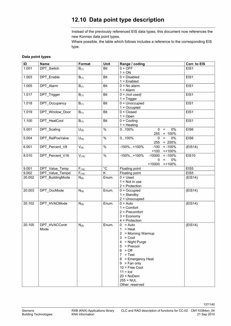
127/140
Siemens RXB (KNX) Applications library CLC and RAD description of functions for CC-02 CM110384en_04 Building Technologies KNX information 21 Sep 2010
12.10 Data point type description
Instead of the previously referenced EIS data types, this document now references the new Konnex data point types. Where possible, the table which follows includes a reference to the corresponding EIS type.
Data point types
ID Name Format Unit Range / coding Corr. to EIS 1.001 DPT_Switch B(1) Bit 0 = OFF
1 = ON EIS1
1.003 DPT_Enable B(1) Bit 0 = Disabled 1 = Enabled
EIS1
1.005 DPT_Alarm B(1) Bit 0 = No alarm 1 = Alarm
EIS1
1.017 DPT_Trigger B(1) Bit 0 = (not used) 1 = Trigger
EIS1
1.018 DPT_Occupancy B(1) Bit 0 = Unoccupied 1 = Occupied
EIS1
1.019 DPT_Window_Door B(1) Bit 0 = Closed 1 = Open
EIS1
1.100 DPT_HeatCool B(1) Bit 0 = Cooling 1 = Heating
EIS1
5.001 DPT_Scaling U(8) % 0...100% 0 = 0% 255 = 100%
EIS6
5.004 DPT_RelPosValve U(8) % 0...100% 0 = 0% 255 = 255%
EIS6
6.001 DPT_Percent_V8 V(8) % -100%...+100% -100 = -100% +100 = +100%
(EIS14)
8.010 DPT_Percent_V16 V(16) % -100%...+100% -10000 = -100% 0 = 0% +10000 = +100%
EIS10
9.001 DPT_Value_Temp F(16) °C Floating point EIS5 9.002 DPT_Value_Tempd F(16) K Floating point EIS5 20.002 DPT_BuildingMode N(8) Enum. 0 = Used
1 = Not in use 2 = Protection
(EIS14)
20.003 DPT_OccMode N(8) Enum. 0 = Occupied 1 = Standby 2 = Unoccupied
(EIS14)
20.102 DPT_HVACMode N(8) Enum. 0 = Auto 1 = Comfort 2 = Precomfort 3 = Economy 4 = Protection
(EIS14)
20.105 DPT_HVACContr Mode
N(8) Enum. 0 = Auto 1 = Heat 2 = Morning Warmup 3 = Cool 4 = Night Purge 5 = Precool 6 = Off 7 = Test 8 = Emergency Heat 9 = Fan only 10 = Free Cool 11 = Ice 20 = NoDem 255 = NUL Other: reserved
(EIS14)

128/140
Siemens RXB (KNX) Applications library CLC and RAD description of functions for CC-02 CM110384en_04 Building Technologies KNX information 21 Sep 2010
ID Name Format Unit Range / coding Corr. to EIS 219.001 DPT_AlarmInfo U(8)U(8)
N(8)N(8) B(8)B(8)
-- Alarm description --
222.100 DPT_TempRoom SetpSetF16[3]
F(16)F(16)F(16) °C 3 floating point values - Comfort - Precomfort - Economy
NEU (3 x EIS5)
222.101 DPT_TempRoom SetpSetShiftF16[3]
F(16)F(16)F(16) K 3 floating point values - Comfort - Precomfort - Economy
NEU (3 x EIS5)

129/140
Siemens RXB (KNX) Applications library CLC and RAD description of functions for CC-02 CM110384en_04 Building Technologies FAQ 21 Sep 2010
13 FAQ
What happens if the parameter download process is interrupted? (power failure, bus failure etc.) The parameter set loaded into the controller is incomplete. The controller does not start properly. Valves may not open. Reload the parameters. Why does the controller fail to start after a parameter download? (applies to HandyTool, ACS or ETS.) Parameter download was probably interrupted or exposed to interference. Reload the controller with the entire parameter set (via HandyTool, ACS or ETS). Why does the controller not start after adjusting certain parameters? (applies to HandyTool.) Parameter download probably interrupted or fault, or controller unloaded via ETS. A complete parameter set must be loaded in the controller (via HandyTool, ACS or ETS). Why does the HandyTool not display parameter 1 upon quick quit and restart of the Display mode? Communication to the HandyTool is relatively slow. You need to wait a brief moment before reopening the Display mode. Why does the HandyTool display "uuuu"? Other parameters have been changed so that the selected parameter became irrele-vant. Just continue your work;. the problem will disappear when the parameterization is started again. ACS: Why is reading back parameters so slow? Check to make sure that neither the operating booklet nor the plant image is active. Both applications cause a lot of bus traffic and thus slow down reading back parameters. ACS: CLC01 shows the lower limit of 21°C for the Comfort cooling setpoint. Setpoint data are only updated when the application (RAD01, CLC01, ...) has been selected.
Question:
Answer:
Question:
Answer:
Question:
Answer:
Question:
Answer:
Question:
Answer:
Question:
Answer:
Question
Answer

130/140
Siemens RXB (KNX) Applications library CLC and RAD description of functions for CC-02 CM110384en_04 Building Technologies FAQ 21 Sep 2010
ACS: Parameter download does not work, why? Make sure that the parameter tree is expanded prior to download.
Wrong Right
Download sometimes also works with a collapsed parameter tree. Why can I not parameterize the controller via HandyTool in service mode (n6)? There are two reasons: Download (HandyTool, ACS or ETS) was not exited correctly (interrupted). The controller was set to "unloaded" via ETS. Solution: Carry out a full download (via HandyTool, ACS or ETS). Why does a controller with thermal valves not respond immediately when it is enabled in the plant graphics in the ACS view and in the DESIGO graphics? After startup, the thermal valves are preheated first. This is not shown in the plant graphic. Why doesn’t the Master/Slave connection work? Master/slave zones must match for master and slave Create master/slave group addresses and add communication object. With master/slave configurations, why do the QAX34 room units not always show the same temperature values? The master-controller and slave-controller data is synchronized regularly. If a value changes just after synchronization, it may be a few minutes until it is resynchronized.
Question:
Answer:
Note
Question:
Answer:
Question:
Answer:
Question:
Answer for LTE mode:
Answer for S-mode:
Question:
Answer:

131/140
Siemens RXB (KNX) Applications library CLC and RAD description of functions for CC-02 CM110384en_04 Building Technologies FAQ 21 Sep 2010
Why does the slave window contact/occupancy contact have no effect? The slave window contact can only be integrated via the CFC. The corresponding compound is available on Swan Web: [WndStaDtr], [OcStaDtr]. For one slave controller: Create group addresses for window contact and add communication object of master and slave. For one ore several slave controllers: In CFC by means of compound [WndStaDtr], [OcStaDtr]. Why does the ACS plant graphic not always display all values (e.g. room operating mode)? The controller is configured as a slave. These values are not available with slave controllers. Why doesn’t the ACS operator book show the current data? After a change of application (e.g. from FNC12 to FNC18), you must update the reference data points. ACS: CLC01 shows the lower limit of 21°C for the Comfort cooling setpoint. Setpoint data are only updated when the application (RAD01, CLC01, ...) has been selected. Why doesn't an RXB controller transmit S-Mode communication objects that it has received? RXB controller do not work as bus relays. If a communication object is required, the binding must be to the source, not to the RXB controller. Example: an RXB controller receives the room temperature from a bus sensor. A bus display is used to display the room temperature. The display must get the signal directly from the bus sensor.
Question:
Answer for LTE mode:
Answer for S-mode:
Question
Answer
Question
Answer
Question
Answer
Question
Answer

132/140
Siemens RXB (KNX) Applications library CLC and RAD description of functions for CC-02 CM110384en_04 Building Technologies Integration of RXB in DESIGO/Synco 21 Sep 2010
14 Integration of RXB in DESIGO/Synco
Combining RXB controllers with Synco and DESIGO integration is possible and sensible.
However, certain types of combination are not allowed, and certain combinations are subject to specific conditions.
Below are the most important combinations. Key
Display
Schedule
Heat demand Refrigeration demand
1038
5D6
9
14.1 Case 1: Integration in Synco
Communication: – Between the controllers: LTE mode via zones. – With ACS: Individual addressing. RXB display: ACS Synco display: ACS RXB schedule: from Synco. Energy demand: to Synco.
Geographical zone
Geographical zone
Geographical zone Time switch zone Heat demand zone Refrigeration demand zone 1
0385
D61
RXB
RXB
RXB
Synco Synco Synco
ACS7..
FLNKonnex
Individual addressing
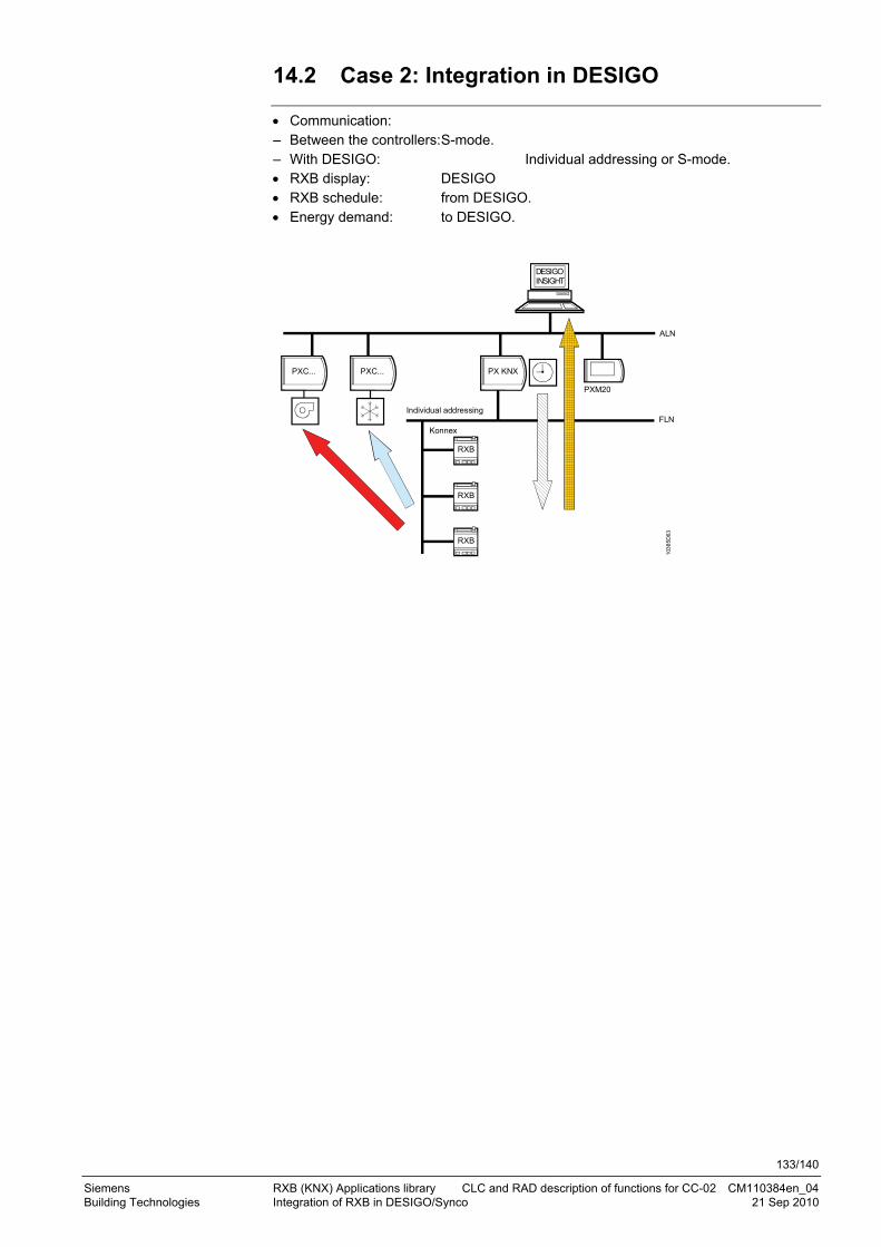
133/140
Siemens RXB (KNX) Applications library CLC and RAD description of functions for CC-02 CM110384en_04 Building Technologies Integration of RXB in DESIGO/Synco 21 Sep 2010
14.2 Case 2: Integration in DESIGO
Communication: – Between the controllers: S-mode. – With DESIGO: Individual addressing or S-mode. RXB display: DESIGO RXB schedule: from DESIGO. Energy demand: to DESIGO.
103
85
D63
PXC... PXC... PX KNX
RXB
RXB
RXB
DESIGOINSIGHT
ALN
FLNKonnex
Individual addressing
PXM20
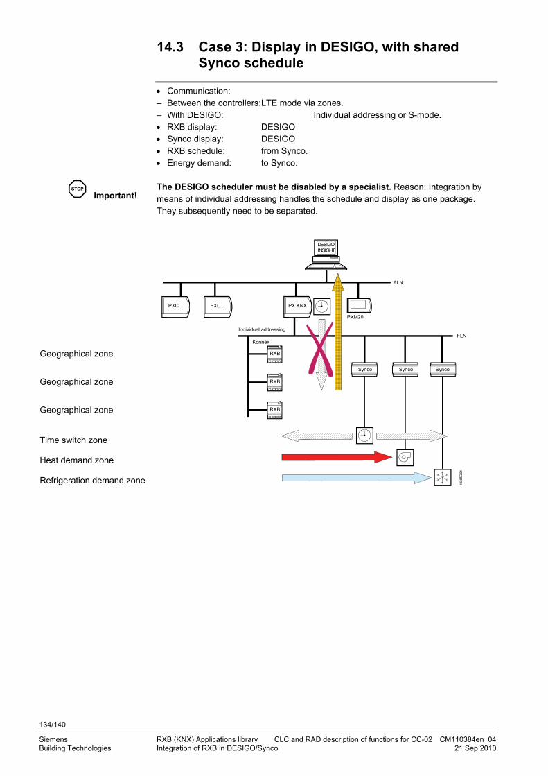
134/140
Siemens RXB (KNX) Applications library CLC and RAD description of functions for CC-02 CM110384en_04 Building Technologies Integration of RXB in DESIGO/Synco 21 Sep 2010
14.3 Case 3: Display in DESIGO, with shared Synco schedule
Communication: – Between the controllers: LTE mode via zones. – With DESIGO: Individual addressing or S-mode. RXB display: DESIGO Synco display: DESIGO RXB schedule: from Synco. Energy demand: to Synco. The DESIGO scheduler must be disabled by a specialist. Reason: Integration by means of individual addressing handles the schedule and display as one package. They subsequently need to be separated.
Geographical zone Geographical zone Geographical zone Time switch zone Heat demand zone Refrigeration demand zone
1038
5D64
PXC... PXC... PX KNX
RXB
RXB
RXB
DESIGOINSIGHT
ALN
FLNKonnex
Individual addressing
PXM20
Synco Synco Synco
STOP
Important!
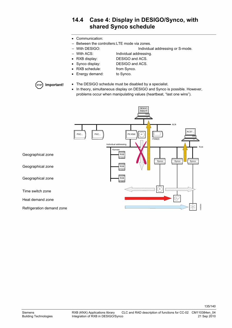
135/140
Siemens RXB (KNX) Applications library CLC and RAD description of functions for CC-02 CM110384en_04 Building Technologies Integration of RXB in DESIGO/Synco 21 Sep 2010
14.4 Case 4: Display in DESIGO/Synco, with shared Synco schedule
Communication: – Between the controllers: LTE mode via zones. – With DESIGO: Individual addressing or S-mode. – With ACS: Individual addressing. RXB display: DESIGO and ACS. Synco display: DESIGO and ACS. RXB schedule: from Synco. Energy demand: to Synco. The DESIGO schedule must be disabled by a specialist. In theory, simultaneous display on DESIGO and Synco is possible. However,
problems occur when manipulating values (heartbeat, “last one wins”).
Geographical zone Geographical zone Geographical zone Time switch zone Heat demand zone Refrigeration demand zone
1038
5D65
PXC... PXC... PX KNX
RXB
RXB
RXB
DESIGOINSIGHT
ALN
FLNKonnex
Individual addressing
PXM20
Synco Synco Synco
ACS7...
STOP
Important!

136/140
Siemens RXB (KNX) Applications library CLC and RAD description of functions for CC-02 CM110384en_04 Building Technologies Integration of RXB in DESIGO/Synco 21 Sep 2010
14.5 Case 5: Display in DESIGO, separate schedules
Communication: – Between the controllers: LTE mode via zones. – With DESIGO: Individual addressing or S-mode. RXB display: DESIGO Synco display: DESIGO RXB schedule: from DESIGO. Energy demand: to Synco. The RXB controllers use the DESIGO schedule. Synco controllers need a local Synco schedule. Both schedules must be synchronized.
Geographical zone Geographical zone Geographical zone Time switch zone Heat demand zone Refrigeration demand zone
1038
5D66
PXC... PXC... PX KNX
RXB
RXB
RXB
DESIGOINSIGHT
ALN
FLNKonnex
Individual addressing
PXM20
Synco Synco Synco
STOP Important!

137/140
Siemens RXB (KNX) Applications library CLC and RAD description of functions for CC-02 CM110384en_04 Building Technologies Integration of RXB in DESIGO/Synco 21 Sep 2010
14.6 Case 6: Separate display, separate schedules
Communication: – Between the controllers: LTE mode via zones. – With DESIGO: Individual addressing or S-mode. – With ACS: Individual addressing. RXB display: DESIGO Synco display: ACS RXB schedule: from DESIGO. Energy demand: to Synco. The RXB controllers use the DESIGO schedule. Synco controllers need a local Synco schedule. Both schedules must be synchronized.
Geographical zone Geographical zone Geographical zone Time switch zone Heat demand zone Refrigeration demand zone
1038
5D67
PXC... PXC... PX KNX
RXB
RXB
RXB
DESIGOINSIGHT
ALN
FLNKonnex
Individual addressing
PXM20
Synco Synco Synco
ACS7..
STOP Important!

138/140
Siemens RXB (KNX) Applications library CLC and RAD description of functions for CC-02 CM110384en_04 Building Technologies Integration of RXB in DESIGO/Synco 21 Sep 2010
14.7 Case 7: Separate display, shared Synco schedule
Communication: – Between the controllers: LTE mode via zones. – With DESIGO: Individual addressing or S-mode. – With ACS: Individual addressing. RXB display: DESIGO Synco display: ACS RXB schedule: from Synco. Energy demand: to Synco. The DESIGO schedule must be disabled by a specialist.
Geographical zone Geographical zone Geographical zone Time switch zone Heat demand zone Refrigeration demand zone
1038
5D68
PXC... PXC... PX KNX
RXB
RXB
RXB
DESIGOINSIGHT
ALN
FLNKonnex
Individual addressing
PXM20
Synco Synco Synco
ACS7..
STOP Important!

139/140
Siemens RXB (KNX) Applications library CLC and RAD description of functions for CC-02 CM110384en_04 Building Technologies Working with different tools 21 Sep 2010
15 Working with different tools
It is possible to prepare the RXB controllers in the office (parameterize in advance) so that only the physical address has to be entered on site. To this end, the HandyTool offers its “small parameterization”. In this case, preparatory work is probably carried out with ACS or ETS rather than the HandyTool. Special caution is required (data consistency) when using more than one tool.
First step Second step
HandyTool ACS ETS
HandyTool () * X **
ACS X **
ETS X *** X ***
* An upload is necessary to avoid losing the data from Step 1. ** The ETS project is missing (no upload possible). *** The ETS project is NOT updated.

140/140
Siemens RXB (KNX) Applications library CLC and RAD description of functions for CC-02 CM110384en_04 Building Technologies Working with different tools 21 Sep 2010