Embed Size (px)
Citation preview

S 400 HYBRIDSupplemental Operating Instructions
221_ZA; 1; 21, en-USd2ureepe, Version: 2.11.8.1
2009-05-13T13:56:31+02:00 - Seite 1

SymbolsThe following symbols are found in thisSupplemental Operating InstructionsBooklet:
G Warning!Warning notices draw your attention tohazards that may endanger your health or life,or the health or life of others.
! Highlights hazards that may result indamage to your vehicle.
i Helpful hints or further information youmay find useful.
X This symbol points to instructionsfor you to follow.
X A number of these symbolsappearing in succession indicatesa multiple-step procedure.
Y page This symbol tells you where to lookfor further information on a topic.
YY This continuation symbol marks awarning or procedure which iscontinued on the next page.
Display Text in displays, such as the controlsystem, are printed in the typeshown here.
221_ZA; 1; 21, en-USd2ureepe, Version: 2.11.8.1
2009-05-13T13:56:31+02:00 - Seite 2

Our company and staff congratulate you onthe purchase of your new Mercedes-Benz.Your selection of our product is ademonstration of your trust in our companyname. Furthermore, it exemplifies your desireto own an automobile that will be as easy aspossible to operate and provide years ofservice.Your Mercedes-Benz represents the efforts ofmany skilled engineers and craftsmen. Tohelp assure your driving pleasure, and alsothe safety of you and your passengers, we askyou to make a small investment of time:RPlease read this manual carefully, then
return it to your vehicle where it will behandy for your reference.RPlease follow the recommendations
contained in this manual. They aredesigned to acquaint you with theoperation of your Mercedes-Benz.RPlease pay attention to the warnings and
cautions contained in this manual. They aredesigned to help improve the safety of thevehicle operator and occupants.
We extend our best wishes for many miles ofsafe, pleasurable driving.Mercedes-Benz USA, LLCA Daimler Company
2215844887 É2215844887kËÍ
221_ZA; 1; 21, en-USd2ureepe, Version: 2.11.8.1
2009-05-13T13:56:31+02:00 - Seite 1

221_ZA; 1; 21, en-USd2ureepe, Version: 2.11.8.1
2009-05-13T13:56:31+02:00 - Seite 2
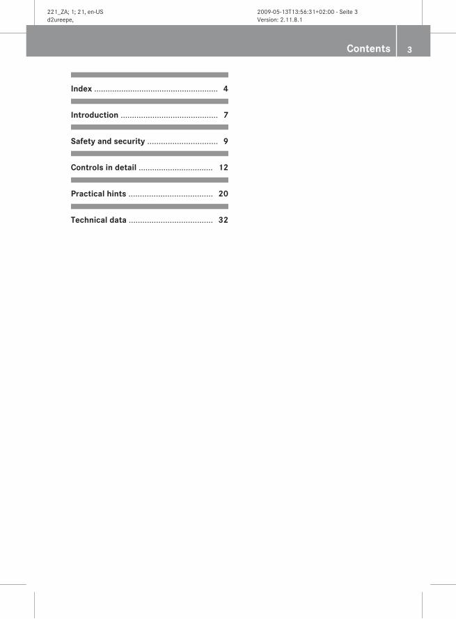
Index ....................................................... 4
Introduction ........................................... 7
Safety and security ............................... 9
Controls in detail ................................. 12
Practical hints ..................................... 20
Technical data ..................................... 32
Contents 3
221_ZA; 1; 21, en-USd2ureepe, Version: 2.11.8.1
2009-05-13T13:56:31+02:00 - Seite 3

AABS (Antilock Brake System) ............. 10
Warning lamp ................................... 24Anticorrosion/antifreeze .................... 36Antilock Brake System
see ABS Automatic transmission
Messages in the multifunctiondisplay ............................................. 21
Axle oils ................................................ 35
BBAS (Brake Assist System) ................. 11Battery
Charging .......................................... 28Charging condition high-voltagebattery (COMAND) ........................... 15Charging condition high-voltagebattery (instrument cluster) ............. 15Jump starting ................................... 29Messages in the multifunctiondisplay ............................................. 22Safety notes ..................................... 26see High-voltage battery
Brake Assist Systemsee BAS
Brakes Messages in the multifunctiondisplay ............................................. 23Warning lamp ................................... 24
Brake systemsee RBS
CCapacities and recommendedfuel/lubricants .................................... 34Charging condition high-voltagebattery (COMAND) ............................... 15Climate control system ...................... 19COMAND
Charging condition high-voltagebattery ............................................. 15Fuel consumption ............................ 16Generated electric power ................ 16Overview .......................................... 14
Combustion engine Malfunction ...................................... 25Starting ............................................ 16
Consumption statistics (COMAND) . . . 16Control system
Overview .......................................... 14Coolant
Anticorrosion/antifreeze ................. 36Capacities ........................................ 35
Cruise control ...................................... 11
DDisplays
Charging condition high-voltagebattery (COMAND) ........................... 15Charging condition high-voltagebattery (instrument cluster) ............. 15Messages in the multifunctiondisplay ............................................. 20Multifunction and COMANDdisplay ............................................. 15
DISTRONIC PLUS ................................. 11Driving and parking
Safety notes ..................................... 16Driving off ............................................ 17Driving safety systems
ABS .................................................. 10BAS .................................................. 11RBS .................................................. 10
Driving systems Cruise control .................................. 11DISTRONIC PLUS ............................. 11
Driving tips .......................................... 18DISTRONIC PLUS ............................. 18
EECO Start/Stop function .................... 17Electric drive
Engine number ................................. 32Engine
see Combustion engine Engine number
Electric drive .................................... 32Enviromental protection ....................... 7ESC (Electronic Stability Control)
Warning lamp ................................... 24
4 Index
221_ZA; 1; 21, en-USd2ureepe, Version: 2.11.8.1
2009-05-13T13:56:31+02:00 - Seite 4
FFlat tire
Spare wheel ..................................... 34Fluids
Automatic transmission fluid ........... 35Brake fluid ....................................... 35Capacities ........................................ 34Engine coolant ................................. 35Engine oil ......................................... 35Power steering fluid ......................... 35Washer and headlamp cleaningsystem ............................................. 35
Fuel Capacity, fuel tank ........................... 35
Fuels, coolants, lubricants etc. .......... 34Fuel tank
Capacity ........................................... 35
HHigh voltage
see Safety notes High-voltage battery ........................... 10
Charging .......................................... 29Charging condition (COMAND) ........ 15Exhaustive discharge ....................... 27Messages in the multifunctiondisplay ............................................. 22Removing/installing cover ............... 27
Hood Messages in the multifunctiondisplay ............................................. 22
HYBRID system Automatic switch-off .................. 10, 26Overview .......................................... 13READY indicator lamp ...................... 16
IIndicator lamp
see Lamps, indicator and warning Instrument cluster .............................. 14
Lamps .............................................. 24Introduction ......................................... 12
JJump starting ....................................... 29Jump start terminal
Removing/installing cover ............... 28
LLamp
see Lamps, indicator and warning Lamps, indicator and warning ............ 24
ABS .................................................. 24Brakes (red) ..................................... 24ESC .................................................. 24Instrument cluster ........................... 24RBS .................................................. 24SRS .................................................. 26
MMessage
see Lamps, indicator and warning Minispare wheel
see Spare wheel Multifunction display
Symbol messages ............................ 22Text messages ................................. 21Vehicle status messages ................. 20
Multifunction display messages Automatic transmission ................... 21Battery ............................................. 22Brakes ............................................. 23Display malfunction ......................... 20Hood ................................................ 22
OOperating safety .................................... 7
PParking ................................................. 18
RRBS (Recuperative BrakeSystem) .......................................... 10, 12
Malfunction ................................ 24, 26Warning lamp ................................... 24
READY indicator lamp ......................... 16
Index 5
221_ZA; 1; 21, en-USd2ureepe, Version: 2.11.8.1
2009-05-13T13:56:31+02:00 - Seite 5

Rear axle oil ......................................... 35Recuperation statistics (COMAND) . . . 16Rims ...................................................... 33Risk of fire
see Safety notes
SSafety
see Operating safety Safety notes ........................................... 9Spare wheel ......................................... 34SRS (Supplemental Restraint System)
Indicator lamp .................................. 26Start/Stop function
see ECO Start/Stop function Starting
see Combustion engine Stop-and-go traffic .............................. 17Submenu
Multifunction and COMANDdisplay ............................................. 14Resetting values (COMAND) ............ 16
TTechnical data
Capacities fuels, coolants,lubricants etc. .................................. 34Coolant ............................................ 36Engine oils ....................................... 36Rims and tires .................................. 33Spare wheel ..................................... 34Vehicle specificationS 400 HYBRID .................................. 32Washer and headlamp cleaningsystem ............................................. 35
Tires ...................................................... 33Towing
Vehicle ............................................. 31Trailer hitch ............................................ 7Turning off
see ECO Start/Stop function
VVehicle
Disuse .............................................. 27Towing ............................................. 31
Vehicle firesee Safety notes
Vehicle modifications ........................... 7Vehicle specification
S 400 HYBRID .................................. 32
WWarning labels ....................................... 9Wheels, sizes ....................................... 33Winter tires .......................................... 33
6 Index
221_ZA; 1; 21, en-USd2ureepe, Version: 2.11.8.1
2009-05-13T13:56:31+02:00 - Seite 6

Enviromental protection
Have the high-voltage battery disposed of inan environment-friendly manner by anauthorized Mercedes-Benz Center.
G Warning!The HYBRID system is energized by highvoltage. The components of the HYBRIDsystem are indicated by yellow warninglabels. High-voltage cables are orange-colored.You could be seriously or even fatally injuredwhen youRtamper with components or high-voltage
cables of the HYBRID systemRtouch components or high-voltage cables
of the HYBRID system after the vehicle hasbeen involved in an accidentRtouch damaged components of the HYBRID
system
Do not remove the high-voltage battery of theHYBRID system. Have the high-voltagebattery disposed of in an environment-friendly manner by an authorized Mercedes-Benz Center.
i For more information on the high-voltagebattery, see (Y page 26).
Operating safety
G Warning!When your vehicle is in electric drive mode theengine produces significantly lower noiselevels. Other motorists or pedestriants,especially those who are visually or hearingimpaired, may be unable to hear your vehiclewhile it is in motion. This is particularly truewhen driving at lower speeds and duringparking maneuvers. At all times, it is theresponsibility of the driver to be aware of theirsurroundings, especially in these low speed
situtations. Otherwise other road users couldbe seriously or fatally injured.
G Warning!Have all work on the vehicle, especially safety-related work, work on safety-relevantsystems, work on the HYBRID system as wellas maintenance work, carried out by anauthorized Mercedes-Benz Center.
i For more information on operating safety,refer to the Operator’s Manual.
Vehicle modifications
G Warning!Improper work on the HYBRID system ormodifications of the vehicle can cause vehiclesystems to cease functioning properly. Youcould lose control over the vehicle and causean accident.Therefore, have work on the HYBRID systemand modifications of the vehicle such asinstallation or modification of vehicleequipment carried out by an authorizedMercedes-Benz Center
i For more information on operating safety,refer to the Operator’s Manual.
Trailer hitch ! Retrofitting the vehicle with a trailer hitch
is not permissible. Damage caused byretrofitting the vehicle with a trailer hitch isnot covered by the Mercedes-Benz LimitedWarranty.
Introduction 7
221_ZA; 1; 21, en-USd2ureepe, Version: 2.11.8.1
2009-05-13T13:56:31+02:00 - Seite 7
Z

Proper use of the vehicleProper use of the vehicle requires that you arefamiliar with the following information andrules:Rthe safety precautions in this manualRthe “Technical data” section in this manualRthe Operator's ManualRtraffic rules and regulationsRmotor vehicle laws and safety standards
8 Introduction
221_ZA; 1; 21, en-USd2ureepe, Version: 2.11.8.1
2009-05-13T13:56:31+02:00 - Seite 8
Safety notes
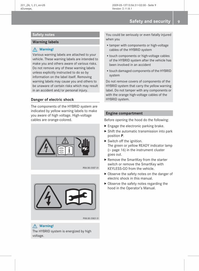
Warning labels
G Warning!Various warning labels are attached to yourvehicle. These warning labels are intended tomake you and others aware of various risks.Do not remove any of these warning labelsunless explicitly instructed to do so byinformation on the label itself. Removingwarning labels may cause you and others tobe unaware of certain risks which may resultin an accident and/or personal injury.
Danger of electric shockThe components of the HYBRID system areindicated by yellow warning labels to makeyou aware of high voltage. High-voltagecables are orange-colored.
G Warning!The HYBRID system is energized by highvoltage.
You could be seriously or even fatally injuredwhen youRtamper with components or high-voltage
cables of the HYBRID systemRtouch components or high-voltage cables
of the HYBRID system after the vehicle hasbeen involved in an accidentRtouch damaged components of the HYBRID
system
Do not remove covers of components of theHYBRID system that carry the yellow warninglabel. Do not tamper with any components orwith the orange high-voltage cables of theHYBRID system.
Engine compartmentBefore opening the hood do the following:X Engage the electronic parking brake.X Shift the automatic transmission into park
position P.X Switch off the ignition.
The green or yellow READY indicator lamp(Y page 16) in the instrument clustergoes out.
X Remove the SmartKey from the starterswitch or remove the SmartKey withKEYLESS-GO from the vehicle.
X Observe the safety notes on the danger ofelectric shock in this manual.
X Observe the safety notes regarding thehood in the Operator’s Manual.
Safety and security 9
221_ZA; 1; 21, en-USd2ureepe, Version: 2.11.8.1
2009-05-13T13:56:31+02:00 - Seite 9
Z

Automatic HYBRID system switch-off The HYBRID system switches offautomatically ifRthe Supplemental Restraint System (SRS)
activates the restraint systems in anaccidentRa short circuit in the HYBRID system is
detectedRa plug connection of the HYBRID system is
disconnectedThese measures help to prevent you fromcoming into contact with high voltage.
High-voltage battery
G Warning!The high-voltage battery of the HYBRIDsystem is located in the engine compartmenton the passenger side of the front wall. Whenthe pressure inside the high-voltage batteryexceeds a certain value, for example in caseof a vehicle fire, inflammable gas will escapevia a duct. The inflammable gas escapes to anarea close to the passenger-side front wheel.This prevents the high-voltage battery fromexploding.Stay away from this area of the vehicle.
Driving safety systems
ABS (Antilock Brake System)
BrakingWhen the ABS engages during braking, theABS/ESC warning lamp ÷ in theinstrument cluster (Y page 14) flashes. Thebrake pedal will pulsate only in certainsituations, for example on a slippery road.
i For more information on the ABS, refer tothe Operator's Manual.
RBS (Recuperative Brake System) The RBS supports you while braking byelectronic controlled brake boost and allowsfor regeneration of braking energy. RBS mustbe activated when the vehicle is parked eachtime before driving off.X Make sure the automatic transmission is in
park position P.X Switch on the ignition.X Apply the brake pedal fully and release it.
The RBS is activated.While you activate the RBS, less brake pedalpressure than usual is required and the brakepedal travel is longer. When you release thebrake pedal, the brake pedal travel is as usualagain.For more information on the RBS, see(Y page 12).
G Warning!If the RBS malfunctions, the yellow RBSwarning lamp é and/or the red brakewarning lamp $ (USA only) or J(Canada only) in the instrument cluster comeson. Read and observe the messages in themultifunction display that may appear. Findthe subentry “Malfunction” of the entry “RBS(Recuperative Brake System)” in the index ofthis manual and follow the steps described inthat section.
G Warning!If the RBS malfunctions, less brake pedalpressure than usual may be required and thebrake pedal travel may be longer. The brakesystem still functions with full effectiveness.If required, you have to depress the brakepedal further. Adapt your speed and drivingaccordingly.
G Warning!Have work on the RBS, e.g. brake padreplacement, carried out by qualifiedtechnicians only.
10 Safety and security
221_ZA; 1; 21, en-USd2ureepe, Version: 2.11.8.1
2009-05-13T13:56:31+02:00 - Seite 10
When working on the RBS, certainprecautions must be taken, e.g. when puttingthe brake system back into service.Contact an authorized Mercedes-BenzCenter. Service conducted by qualifiedtechnicians is required particularly for safety-relevant work and work on safety-relevantsystems such as the RBS.
i For more information on the brakingsystem and for driving instructions, refer tothe Operator’s Manual.
BAS (Brake Assist System) If you apply the brakes very quickly, the RBSprovides full brake boost as fast as possible.In doing so, less brake pedal pressure thanusual is required and the brake pedal travel islonger.X Apply continuous full braking pressure until
the emergency braking situation is over.The ABS will prevent the wheels fromlocking.
i For more information on the BAS, refer tothe Operator’s Manual.
Driving systems
Cruise control/DISTRONIC PLUS* When the cruise control or the DISTRONICPLUS brake the vehicle, the brake pedal is notdepressed.For information on driving with theDISTRONIC PLUS, see (Y page 18).
i For more information on the cruisecontrol and the DISTRONIC PLUS, refer tothe Operator’s Manual.
Safety and security 11
* optional
221_ZA; 1; 21, en-USd2ureepe, Version: 2.11.8.1
2009-05-13T13:56:31+02:00 - Seite 11
Z

Introduction
The HYBRID technology combines aneconomical combustion engine with apowerful electric drive. The HYBRID systemselects the most efficient operating mode foreach driving situation automatically. You candrive the vehicle in the usual manner.The HYBRID system turns the combustionengine off when stopping as often as possiblein order to save fuel. You will just have tocontinue to keep the brake pedal depressedor to activate the HOLD function. Thus, theengine should normally never run at idlespeed.When you remove the foot from the brakepedal or accelerate when the HOLD functionis activated, the combustion engine startsautomatically. You can drive off as usual.
G Warning!When the green READY indicator lamp in theinstrument cluster is on while the combustionengine is off, the combustion engine has beenturned off automatically. All vehicle systemscontinue to be active. When you open thedriver’s door, unbuckle the seat belt, or takeyour foot off of the brake pedal, thecombustion engine starts automatically. Thevehicle could start to drive off. An accidentcausing serious or even fatal personal injuryto you and/or others could be the result.Therefore, always do the following beforeleaving the vehicle:REngage the electronic parking brake.RShift the automatic transmission into park
position P.RSwitch off the ignition. The green or yellow
READY indicator lamp goes out.
Driving off and accelerating consumes themost energy. Thus, the electric drive supportsthe combustion engine with the energy storedin the high-voltage battery. The energy is alsoused for semi-electrical driving, for operationof the electric compressor of the coolingsystem and to support the 12-volt on-boardpower supply. The hybrid drive therebycontributes significantly to the fuel economyof your vehicle.For information on driving and parking, see(Y page 16).The current operating mode of the HYBRIDsystem can be displayed in the multifunctiondisplay and in the COMAND display(Y page 14).The COMAND can also display a chart of thefuel consumption and the electric power thathas been generated (Y page 16).
RBS With the RBS activated (Y page 10), theelectric drive functions as a generator whencoasting and braking. HYBRID converts theenergy of movement into electric power andstores it in the high-voltage battery. The high-voltage battery does not require additionalcharging by other means.
12 Controls in detail
221_ZA; 1; 21, en-USd2ureepe, Version: 2.11.8.1
2009-05-13T13:56:31+02:00 - Seite 12

Overview HYBRID system
Component
: 12-volt battery
; Voltage transformer(transforms the voltage of the 12-voltbattery and the high-voltage battery inboth directions for best possiblepower management)
= High-voltage battery
Component
? Electric drive
A Electric refrigerant compressor forthe climate control system
B Power electronics(control the high-voltage system)
C Combustion engine
Controls in detail 13
221_ZA; 1; 21, en-USd2ureepe, Version: 2.11.8.1
2009-05-13T13:56:31+02:00 - Seite 13
Z

Instrument cluster
Function Page
: ÷ ABS/ESC warninglamp
10,24
; $ Brake warning lamp,USA only 24J Brake warning lamp,Canada only 24
= é Recuperative BrakeSystem (RBS) warning lamp 24
? Green or yellow READYindicator lamp for theHYBRID system 16
A Multifunction display with:Charging level high-voltagebattery 15
Control system and COMAND
i For information on the instrument clustercontrol system and COMAND operation,refer to the Operator’s Manual.
The current operating mode of the HYBRIDsystem can be displayed in the multifunctiondisplay and in the COMAND.The COMAND can also display a chart of thefuel consumption and the electric power thathas been generated (Y page 16).
Selecting submenu in the multifunction display
Use the buttons on the multifunction steeringwheel.X Press button = or ; to select theTrip menu.
X Press button 9 or : to select theHYBRID menu.
Selecting submenu in the COMAND displayX Select Vehicle Q Hybrid Q Energy.
14 Controls in detail
221_ZA; 1; 21, en-USd2ureepe, Version: 2.11.8.1
2009-05-13T13:56:31+02:00 - Seite 14

Multifunction display and COMAND display examples
Example illustration: Operating mode display1 Combustion engine2 Electric drive
3 High-voltage battery4 Charging condition of high-voltage
battery in percent 5 Flow of energyThe HYBRID components that are currentlyactive are highlighted in the multifunctiondisplay and the COMAND display.
Multifunction display
COMAND display Operating mode
The electric drive functions as agenerator when coasting andbraking. HYBRID converts theenergy of movement into electricpower and stores it in the high-voltage battery.The arrows that indicate the flowof energy are green.
Boost effect – the electric drivesupports the combustion enginewhen driving off and whenaccelerating.The arrows that indicate the flowof energy are red.
Normal driving – the combustionengine powers the vehicle.The arrows that indicate the flowof energy are white.
Controls in detail 15
221_ZA; 1; 21, en-USd2ureepe, Version: 2.11.8.1
2009-05-13T13:56:31+02:00 - Seite 15
Z

Displaying fuel consumption and generated electric power
The COMAND display indicates the fuelconsumption and the generated electricpower for the last 15 minutes of driving.X Select Vehicle Q Hybrid QConsumption.
1 Fuel consumption2 Generated electric powerEach bar in the chart represents the averagevalue for 1 minute.Average fuel consumption 1 can differ fromthe fuel consumption that is displayed in theFrom Start submenu in the Trip menu.
Resetting values The values are reset together when resettingthe trip computer in the From Startsubmenu. Refer to the Operator’s Manual.
Driving and parking
Safety notes
G Warning!When your vehicle is in electric drive mode theengine produces significantly lower noiselevels. Other motorists or pedestriants,especially those who are visually or hearingimpaired, may be unable to hear your vehiclewhile it is in motion. This is particularly truewhen driving at lower speeds and duringparking maneuvers. At all times, it is the
responsibility of the driver to be aware of theirsurroundings, especially in these low speedsitutations. Otherwise other road users couldbe seriously or fatally injured.
G Warning!Make sure absolutely no objects areobstructing the pedals’ range of movement.Keep the driver’s footwell clear of allobstacles. If there are any floormats orcarpets in the footwell, make sure the pedalsstill have sufficient clearance.During sudden driving or braking maneuversthe objects could get caught between orunder the pedals. You could then no longerbrake or accelerate. This could lead toaccidents and injury.
Starting the engine
: Green or yellow READY indicator lamp
X Switch on the ignition.X Apply the brake pedal fully and release it to
activate the RBS.The RBS is activated. For more informationon the RBS, see (Y page 10).
X Observe the notes on “Starting the engine”in the Operator’s Manual and start thecombustion engine.The vehicle is operational when the greenor yellow READY indicator lamp : isilluminated.
16 Controls in detail
221_ZA; 1; 21, en-USd2ureepe, Version: 2.11.8.1
2009-05-13T13:56:31+02:00 - Seite 16

ECO Start/Stop function When the green READY indicator lamp : inthe instrument cluster is on, the combustionengine turns off automatically whenRyou stop the vehicle and keep the brake
pedal depressedRyou activate the HOLD functionAll vehicle systems remain active, forexample the climate control system.When you remove the foot from the brakepedal or accelerate when the HOLD functionis activated, the combustion engine startsautomatically. You can drive off as usual.
G Warning!When the green READY indicator lamp in theinstrument cluster is on while the combustionengine is off, the combustion engine has beenturned off automatically. All vehicle systemscontinue to be active. When you open thedriver’s door, unbuckle the seat belt, or takeyour foot off of the brake pedal, thecombustion engine starts automatically. Thevehicle could start to drive off. An accidentcausing serious or even fatal personal injuryto you and/or others could be the result.Therefore, always do the following beforeleaving the vehicle:REngage the electronic parking brake.RShift the automatic transmission into park
position P.RSwitch off the ignition. The green or yellow
READY indicator lamp goes out.
The conditions for turning off the combustionengine automatically are fulfilled whenRthe combustion engine has reached its
operating temperatureRthe driver seat belt is fastened and the
driver’s door is closedRthe vehicle has exceeded a speed of 9 mph
(15 km/h) after driving off. In subsequentstop-and-go traffic, brief forwardmovement of the vehicle is sufficient
Ryou take your foot off the accelerator pedalRthe hood is closed and properly engagedRthe automatic transmission is in drive
position D or neutral position NRthe high-voltage battery is charged
sufficientlyRthe HYBRID system is operating
undisturbed
i For information on driving with theDISTRONIC Plus, see (Y page 18).
When the conditions for turning off the engineautomatically are not fulfilled, the yellowREADY indicator lamp : is illuminated. Thecombustion engine does not turn offautomatically whenRthe self-diagnosis of the engine
management is still runningRthe temperature of the coolant or the
catalyst is too lowRthe climate control system of the vehicle
requires the engine to runRthe battery is being chargedRthe vehicle has moved backward shortly
beforeRthe automatic transmission is in reverse
gear RRautomatic emission tests are in progressAfter the combustion engine has been turnedoff automatically, it restarts automatically incircumstances, whenRthe charging condition of the high-voltage
battery has reached the lower limitRthe settings of the climate control systems
require the engine to run, for example at anoutside temperature over 100‡ (38 †)
Driving offDepress the brake pedal and shift theautomatic transmission into drive position Dor reverse gear R. If the message Apply
Controls in detail 17
221_ZA; 1; 21, en-USd2ureepe, Version: 2.11.8.1
2009-05-13T13:56:31+02:00 - Seite 17
Z

Brake to Shift from 'P' appears in themultifunction display:X Depress the brake pedal with somewhat
greater force and select the desiredtransmission position.
i Read and observe messages that mayappear in the multifunction display(Y page 20)For more information on driving off, refer tothe Operator’s Manual.
Driving
Driving tipsRThink ahead and keep sufficient distance.RAvoid frequent and rapid acceleration as
well as abrupt braking.RIn semi-electric operation, when driving off
and when accelerating, the electric drivesupports the combustion engine.RThe electric drive functions as a generator
when coasting the vehicle with theautomatic transmission in drive position Dand during braking.
i For more information on the ECO Start/Stop function, see (Y page 17). Foradditional general driving instructions,refer to the Operator’s Manual.
Driving with activated DISTRONIC PLUS When the DISTRONIC PLUS recognizes thatthe preceding vehicle stops, it will brake yourvehicle to a complete stop. The combustionengine is turned off automatically only afterboth vehicles have come to a complete stop.The green READY indicator lamp in theinstrument cluster continues to beilluminated.
i For more information on the ECO Start/Stop function, see (Y page 17). For
additional information on the DISTRONICPLUS, refer to the Operator’s Manual.
Parking
G Warning!When your vehicle is in electric drive mode theengine produces significantly lower noiselevels. Other motorists or pedestriants,especially those who are visually or hearingimpaired, may be unable to hear your vehiclewhile it is in motion. This is particularly truewhen driving at lower speeds and duringparking maneuvers. At all times, it is theresponsibility of the driver to be aware of theirsurroundings, especially in these low speedsitutations. Otherwise other road users couldbe seriously or fatally injured.
G Warning!When the green READY indicator lamp in theinstrument cluster is on while the combustionengine is off, the combustion engine has beenturned off automatically. All vehicle systemscontinue to be active. When you open thedriver’s door, unbuckle the seat belt, or takeyour foot off of the brake pedal, thecombustion engine starts automatically. Thevehicle could start to drive off. An accidentcausing serious or even fatal personal injuryto you and/or others could be the result.Therefore, always do the following beforeleaving the vehicle:REngage the electronic parking brake.RShift the automatic transmission into park
position P.RSwitch off the ignition. The green or yellow
READY indicator lamp goes out.
18 Controls in detail
221_ZA; 1; 21, en-USd2ureepe, Version: 2.11.8.1
2009-05-13T13:56:31+02:00 - Seite 18

X Engage the electronic parking brake.The parking brake indicator lamp $(USA only) or ! (Canada only) in theinstrument cluster comes on.
X Shift the automatic transmission into parkposition P.
X Switch off the ignition.The green or yellow READY indicator lampgoes out.
i For more information on parking and onturning off the combustion engine, refer tothe Operator’s Manual.
Climate control
NotesThe climate control system is available whenthe vehicle is operational and the green oryellow READY indicator lamp is on.The set temperature of the vehicle interior ismaintained for a certain period after thecombustion engine was turned offautomatically. Air recirculation switches onautomatically. The indicator lamp in rockerswitch g is not lit when the airrecirculation mode is switched onautomatically.
Air conditioning switched on automaticallyIf the operating temperature of the high-voltage battery is too high, it will be cooled bythe climate control system. The airconditioning switches on automatically.In such circumstances it is not possible toswitch off the air conditioning via COMANDfor several minutes.
i For more information on the climatecontrol system, refer to the Operator’sManual.
Controls in detail 19
221_ZA; 1; 21, en-USd2ureepe, Version: 2.11.8.1
2009-05-13T13:56:31+02:00 - Seite 19
Z

Vehicle status messages in the multifunction display
NotesWarning and malfunction messages appear inthe multifunction display located in theinstrument cluster. Certain warning andmalfunction messages are accompanied byan audible signal.High-priority messages are shown in red inthe multifunction display. Messages of lowerpriority are also shown in yellow or white.Address these messages accordingly andfollow the additional instruction given in thisSupplemental Operating Instructions Bookletand in the Operator’s Manual.
G Warning!All categories of messages contain importantinformation which should be taken note ofand, where a malfunction is indicated,addressed as soon as possible at anauthorized Mercedes-Benz Center.Failure to repair the condition noted maycause damage not covered by the Mercedes-Benz Limited Warranty, or result in propertydamage or personal injury.
G Warning!No messages will be displayed if either theinstrument cluster or the multifunctiondisplay is inoperative.As a result, you will not be able to seeinformation about your driving conditions,such asRspeedRoutside temperature
Rwarning/indicator lampsRmalfunction/warning messagesRfailure of any systems
Driving characteristics may be impaired.If you must continue to drive, do so with addedcaution. Contact an authorized Mercedes-Benz Center as soon as possible.
On the pages that follow, you will find acompilation of the warning and malfunctionmessages specific to the HYBRID system. Forall other warning and malfunction messages,refer to the Operator’s Manual.
Clearing display messagesSome display messages with low priority arecleared from the multifunction display afterseveral seconds. Other display messagesremain displayed in the multifunction displayuntil you clear them manually.Certain messages of high priority cannot becleared from the multifunction display. Suchmessages will appear in the multifunctiondisplay until the causes for these messageshave been repaired.Use the buttons on the multifunction steeringwheel.X Clear the messages using button a or%.Certain messages are stored in the vehiclestatus message memory. For informationon calling up vehicle malfunction, warningand system status messages stored inmemory, refer to the Operator’s Manual.
20 Practical hints
221_ZA; 1; 21, en-USd2ureepe, Version: 2.11.8.1
2009-05-13T13:56:31+02:00 - Seite 20

Text messages
Display messages Possible causes/consequences and X Solutions
Apply Brake
to Shift from 'P'
You have attempted to shift the automatic transmission intodrive position D, reverse gear R or neutral position N withoutdepressing the brake pedal or without depressing it fully.X Depress the brake pedal fully.
Service Required
Do not turn engine off or start engine again
The HYBRID system is malfunctioning. The engine speed ofthe combustion engine may be limited to 2000 rpm. Whenyou turn the combustion engine off, it cannot be restarted.The ECO Start/Stop function is not available. In addition, anacoustic warning sounds.X Do not turn off the combustion engine.X Contact an authorized Mercedes-Benz Center.
Engine Can Now Be Started
The high-voltage battery has been charged via the voltagetransformer automatically.X Start the combustion engine and drive the vehicle for some
time in order to charge the 12-volt battery and the high-voltage battery.
Practical hints 21
221_ZA; 1; 21, en-USd2ureepe, Version: 2.11.8.1
2009-05-13T13:56:31+02:00 - Seite 21
Z

Symbol messages
Display messages Possible causes/consequences and X Solutions
L The hood is open. The combustion engine cannot be started.Risk of accident!X Close the hood.
c Charging Hybrid Battery Please Wait
The high-voltage battery is discharged. You have switched onthe ignition while the 12-volt battery was being charged withan approved charge unit or while jump starting the vehicle.The high-voltage battery is being charged via the voltagetransformer automatically. The message Engine Can Now Be Started appears in the multifunction display after a fewminutes.X Start the combustion engine.X Disconnect the charge unit and drive the vehicle for some
time in order to charge the 12-volt battery and the high-voltage battery.
If the display message Engine Can Now Be Started doesnot appear after a few minutes:X Try to start the combustion engine.X If the combustion engine cannot be started: Contact an
authorized Mercedes-Benz Center.
c Malfunction
The combustion engine cannot be started. In addition, anacoustic warning sounds.X Contact an authorized Mercedes-Benz Center.
The combustion engine is running and the HYBRID system ismalfunctioning. In addition, an acoustic warning sounds.X Contact an authorized Mercedes-Benz Center.
The combustion engine is running and the HYBRID system ismalfunctioning. In addition, an acoustic warning sounds.Extreme operating conditions such as driving throughstanding water can cause very high moisture in the enginecompartment.The message disappears once the engine compartment is dry.
22 Practical hints
221_ZA; 1; 21, en-USd2ureepe, Version: 2.11.8.1
2009-05-13T13:56:31+02:00 - Seite 22

Display messages Possible causes/consequences and X Solutions
d Malfunction
The engine stalled when driving off.X Shift the automatic transmission into park position P.X Switch off the ignition and switch it back on.X Start the combustion engine.
The HYBRID system is malfunctioning. The ECO Start/Stopfunction may have failed and the vehicle may accelerateslower than usual.X Contact an authorized Mercedes-Benz Center.
The combustion engine cannot be started.X Contact an authorized Mercedes-Benz Center.
J Caution Brakes Overheated Drive Carefully
The brake system is very hot due to extreme brake load.Relieve the load on the brake system.X Exercise a more anticipatory driving style.X Use the engine’s braking power on downgrades. Shift the
automatic transmission into a lower gear.X Continue to drive with added caution so the air stream can
cool the brakes.
Practical hints 23
221_ZA; 1; 21, en-USd2ureepe, Version: 2.11.8.1
2009-05-13T13:56:31+02:00 - Seite 23
Z

What to do if ...
Lamps in instrument cluster
Problem Possible causes/consequences and X Solutions
éThe yellow RBS(Recuperative BrakeSystem) warning lampis on while thecombustion engine isrunning. In addition, anacoustic warning maysound.
The RBS is malfunctioning.Risk of accident!Brake pedal travel may be longer than usual and the brakingbehavior of the vehicle may change. The ECO Start/Stop functionmay also be switched off.X Read and observe messages that may appear in the
multifunction display (Y page 20).X Continue driving with added caution.X Contact an authorized Mercedes-Benz Center.
$(USA only)J(Canada only)The red brake warninglamp is on while thecombustion engine isrunning. An additionalacoustic warningsounds.
The RBS is malfunctioning.Risk of accident!Brake pedal travel may be longer than usual and the brakingbehavior of the vehicle may change.X Stop the vehicle in a safe location or as soon as it is safe to do
so. Do not continue to drive.X Contact an authorized Mercedes-Benz Center immediately.X Read and observe messages that may appear in the
multifunction display (Y page 20), see Operator’s Manual.
The brake fluid level in the brake fluid reservoir is too low.Risk of accident!X Stop the vehicle in a safe location or as soon as it is safe to do
so. Do not continue to drive.X Contact an authorized Mercedes-Benz Center immediately.X Read and observe messages that may appear in the
multifunction display (Y page 20), see Operator’s Manual.Do not add brake fluid. This will not solve the problem.
÷The yellow ABS/ESCwarning lamp flasheswhile driving.
The ESC, the ETS, or the ABS has come into operation because ofdetected traction loss for at least one wheel.Risk of accident!The cruise control or the DISTRONIC PLUS is deactivated.X When driving off, apply as little throttle as possible.X While driving, ease up on the accelerator pedal.X Adapt your speed and driving to the prevailing road and weather
conditions.X Do not switch off the ESC.
Exceptions, see Operator’s Manual.
24 Practical hints
221_ZA; 1; 21, en-USd2ureepe, Version: 2.11.8.1
2009-05-13T13:56:31+02:00 - Seite 24

Problem Possible causes/consequences and X Solutions
The warning andindicator lamps in theinstrument cluster failto come on whenswitching on theignition.
The 12-volt battery is discharged.X Get a jump start (Y page 29).orX Charge the 12-volt battery (Y page 28).orX Contact an authorized Mercedes-Benz Center.
Combustion engine
Problem Possible causes/consequences and X Solutions
The combustion enginecannot be started. Thewarning and indicatorlamps in the instrumentcluster come on whenswitching the ignition.The messageCharging Hybrid Battery Please Wait appears in themultifunction display.
The high-voltage battery is discharged.The discharged high-voltage battery is being charged with theignition switched on, provided the 12-volt battery is chargedsufficiently and an approved charge unit is connected.X Read and observe messages that may appear in the
multifunction display (Y page 22).
The combustion enginecannot be started. Themultifunction displaydoes not display anymessages.
The self-diagnosis has not been completed yet or the HYBRIDsystem is malfunctioning.X Switch off the ignition and switch it back on.X Try to start the combustion engine once more.X If the combustion engine cannot be started: Contact an
authorized Mercedes-Benz Center.
The ECO Start/Stopfunction does not startthe combustion enginewhen attempting todrive off.
The ECO Start/Stop function may be malfunctioning. The lampsin the instrument cluster are on.X Shift the automatic transmission into park position P.X Switch off the ignition and switch it back on.X Start the combustion engine.
The HYBRID system is malfunctioning.X Contact an authorized Mercedes-Benz Center.
Practical hints 25
221_ZA; 1; 21, en-USd2ureepe, Version: 2.11.8.1
2009-05-13T13:56:31+02:00 - Seite 25
Z

RBS (Recuperative Brake System)
Problem Possible causes/consequences and X Solutions
Less brake pedalpressure is requiredand the brake pedaltravel is longer thanusual.
X Apply the brake pedal fully and release it.The required brake pedal pressure and the brake pedal travelare back to normal.
The RBS is malfunctioning.Risk of accident!X Read and observe the messages in the multifunction display and
the notes on warning and indicator lamps in the instrumentcluster (Y page 24).
The brake pedalpulsates.
The RBS is providing electronic controlled brake boost. Read andobserve the notes on the ABS/ESC warning lamp (Y page 10).
The HYBRID system switches of automatically
Problem Possible causes/consequences and X Solutions
The HYBRID systemhas switched offautomatically.
Your vehicle was involved in an accident.The HYBRID system remains switched off, ifRthe combustion engine cannot be started again after a few
secondsRthe red SRS indicator lamp 6 in the instrument cluster
comes onX Contact an authorized Mercedes-Benz Center.
The HYBRID systemhas switched offautomatically. Anadditional messageappears in themultifunction display.
A short circuit in the HYBRID system has occurred or a plugconnection of the HYBRID system was disconnected.X Read and observe messages that may appear in the
multifunction display (Y page 20).X Contact an authorized Mercedes-Benz Center.
Battery
NotesYour vehicle is equipped with a 12-voltbattery and a high-voltage battery. The high-voltage battery stores the power required forthe electric drive. The electric drive alsostarts the combustion engine.
Have any work on the batteries performed atan authorized Mercedes-Benz Center.
i Read and observe the safety notes(Y page 9) and the notes on the 12-voltbattery in the Operator’s Manual.
26 Practical hints
221_ZA; 1; 21, en-USd2ureepe, Version: 2.11.8.1
2009-05-13T13:56:31+02:00 - Seite 26

G Warning!The electrolyte, i.e. the battery fluid, is toxicand caustic. Do not allow this fluid to come incontact with eyes, skin or clothing, forexample in case of an accident.In case it does, immediately flush affectedarea with water and seek medical helpimmediately.
For information on the location of the 12-voltbattery and the high-voltage battery, see(Y page 13).
! Deep discharge caused by prolongedperiods of the vehicle not being used, candamage the high-voltage battery.During such periods, operate the vehicleevery 4 weeks for several minutes in orderto charge the high-voltage battery.During the charging process, switch offelectrical consumers that are currently notneeded, e.g. climate control system or seatheating.If necessary, get a jump start.
G Warning!Inhalation of exhaust gas is hazardous to yourhealth. All exhaust gas contains carbonmonoxide (CO), and inhaling it can causeunconsciousness and lead to death. Do notrun the engine in confined areas (such as agarage) which are not properly ventilated.
If you do not intend to operate your vehiclefor an extended period of time, contact anauthorized Mercedes-Benz Center aboutsteps you need to observe.
Removing/installing high-voltage battery coverX Engage the electronic parking brake.X Shift the automatic transmission into park
position P.
X Switch off the ignition.The green or yellow READY indicator lamp(Y page 16) in the instrument cluster goesout.
X Remove the SmartKey from the starterswitch or remove the SmartKey withKEYLESS-GO from the vehicle.
X Observe the safety notes on the danger ofelectric shock in this manual.
X Observe the safety notes regarding thehood in the Operator's manual.
X Open the hood, see Operator's Manual.
Removing
X Turn locks 1 clockwise by 90°.X Lift cover 2 as indicated by the arrows and
remove it forward as seen in drivingdirection.
X Store cover 2 in the trunk for example.
Installing
Practical hints 27
221_ZA; 1; 21, en-USd2ureepe, Version: 2.11.8.1
2009-05-13T13:56:31+02:00 - Seite 27
Z
X Place cover 1 onto the high-voltagebattery carefully.
X Push holder 2 onto pin 3.
X Turn locks 4 counterclockwise by 90°.The cover is locked.
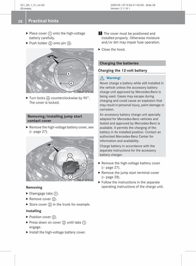
Removing/installing jump start contact coverX Remove the high-voltage battery cover, see
(Y page 27).
RemovingX Disengage tabs :.X Remove cover ;.X Store cover 2 in the trunk for example.
InstallingX Position cover ;.X Press down on cover ; until tabs 1
engage.X Install the high-voltage battery cover.
! The cover must be positioned andinstalled properly. Otherwise moistureand/or dirt may impair fuse operation.
X Close the hood.
Charging the batteries
Charging the 12-volt battery
G Warning!Never charge a battery while still installed inthe vehicle unless the accessory batterycharge unit approved by Mercedes-Benz isbeing used. Gases may escape duringcharging and could cause an explosion thatmay result in personal injury, paint damage orcorrosion.An accessory battery charge unit speciallyadapted for Mercedes-Benz vehicles andtested and approved by Mercedes-Benz isavailable. It permits the charging of thebattery in its installed position. Contact anauthorized Mercedes-Benz Center forinformation and availability.Charge battery in accordance with theseparate instructions for the accessorybattery charger.
X Remove the high-voltage battery cover(Y page 27).
X Remove the jump start terminal cover(Y page 28).
X Follow the instructions in the separateoperating instructions of the charge unit.
28 Practical hints
221_ZA; 1; 21, en-USd2ureepe, Version: 2.11.8.1
2009-05-13T13:56:31+02:00 - Seite 28

X Connect the positive terminal clamp of thecharge unit with jump start terminal 1.
X Connect the negative terminal clamp of thecharge unit with jump start terminal 2.
X Charge the 12-volt battery.
Charging the high-voltage battery With the ignition switched on, the dischargedhigh-voltage battery is being charged via thevoltage transformer, provided the 12-voltbattery is charged sufficiently. During thecharging procedure the charge unit mustremain connected to the jump startterminals.
i The high-voltage battery can only becharged via the 12-volt battery of yourvehicle. Observe the safety notes(Y page 9).
X Switch on the ignition.The lamps in instrument cluster are on. Themessage Charging Hybrid Battery Please Wait appears in the multifunctiondisplay.Start the combustion engine when themessage Engine Can Now Be Startedappears in the multifunction display after afew minutes.
Disconnecting the charge unitX Disconnect the charge unit. Follow the
instructions in the separate operatinginstructions of the charge unit.
X Install the jump start terminal cover(Y page 28).
X Install the high-voltage battery cover(Y page 27).
X Close the hood.X Drive the vehicle for some time in order to
charge the 12-volt battery and the high-voltage battery.
Jump starting
When the 12-volt battery is discharged, thecombustion engine can be started withjumper cables and the battery of anothervehicle.Observe the following:RJump starting should only be performed
when the combustion engine and thecatalytic converter are cold.RDo not jump start if the battery is frozen.
Let the battery thaw out first.ROnly jump start from batteries with the
same voltage rating (12 V). Jump startingwith a more powerful battery could damagethe vehicle’s electrical system, which is notcovered by the Mercedes-Benz LimitedWarranty.ROnly use jumper cables with sufficient
cross-section and insulated terminalclamps.RAlways make sure the jumper cables are
not on or near pulleys, fans or other partsthat move when an engine is started orrunning.RShould the battery be drained completely,
let the donating power source charge thevehicle for several minutes beforereattempting the starting process.
Practical hints 29
221_ZA; 1; 21, en-USd2ureepe, Version: 2.11.8.1
2009-05-13T13:56:31+02:00 - Seite 29
Z

i Jumper cables and additional informationon jump starting are available at anyauthorized Mercedes-Benz Center.
! Jump starting should only be performedusing the jump-start terminals located inthe engine compartment.Avoid repeated and lengthy startingattempts.Do not attempt to start the engine using abattery quick-charge unit.If the engine does not run after severalunsuccessful starting attempts, have itchecked at the nearest authorizedMercedes-Benz Center.Excessive unburned fuel generated byrepeated failed starting attempts maydamage the catalytic converter and maypresent a fire risk.Make sure the jumper cables do not haveloose or missing insulation.Make sure the cable clamps do not touchany other metal part while the other end isstill attached to a battery.
Connecting the jumper cablesX Make sure the two vehicles do not touch.X Remove the high-voltage battery cover
(Y page 27).X Remove the jump start terminal cover
(Y page 28).
Your vehicle is equipped with two jump startterminals in the engine compartment.
X Connect jump start terminal = withpositive terminal ; of the external batterywith a jumper cable. Clamp the jumpercable to jump start terminal 3 first.
X Connect negative terminal 1 of theexternal battery with jump start terminal4 with a jumper cable. Clamp the jumpercable to negative terminal 1 of theexternal battery first.
Starting the combustion engineX Start the engine of the vehicle with the
charged battery and run it at an enginespeed slightly above idle speed.
X Switch on the ignition of your vehicle.The lamps in the instrument cluster comeon. Wait to start the combustion engine, ifthe message Charging Hybrid Battery Please Wait appears in the multifunctiondisplay.Start the combustion engine only after themessage Engine Can Now Be Startedhas appeared in the multifunction display.This may take a few minutes.If no messages appear in themultifunctional display, you can start thecombustion engine directly.
X After the combustion engine of your vehiclehas been started, leave the engines of bothvehicles running at idle speed.
30 Practical hints
221_ZA; 1; 21, en-USd2ureepe, Version: 2.11.8.1
2009-05-13T13:56:31+02:00 - Seite 30

Disconnecting the jumper cablesX Disconnect the jumper cables in reverse
order, starting with jump start terminal 4(Y page 30).
X Install the jump start terminal cover(Y page 28).
X Install the high-voltage battery cover(Y page 27).
X Close the hood.X Drive the vehicle for some time in order to
charge the 12-volt battery and the high-voltage battery.
Towing the vehicle
i For information on towing andtransporting the vehicle refer to theOperator’s Manual.
G Warning!When you depress the brake pedal for the firsttime when towing, less brake pedal pressureis required and the brake pedal travel is longerthan usual. The same applies if a malfunctionoccurs, for example when the vehicle systemvoltage is too low. If required, you have todepress the brake pedal further. Adapt yourspeed and driving accordingly.Depress the brake pedal fully and release itagain before towing. When all necessarysystems are operational again, the requiredbrake pedal pressure and the brake pedaltravel are back to normal.
Practical hints 31
221_ZA; 1; 21, en-USd2ureepe, Version: 2.11.8.1
2009-05-13T13:56:31+02:00 - Seite 31
Z

Identification labels
i For more information on the identificationlabels, refer to the Operator’s Manual.
Electric drive
The engine number is engraved on thehousing of the electric drive. For moreinformation contact an authorized Mercedes-Benz Center.
Vehicle specification S 400 HYBRID (221.195)
The quoted data apply only to the standardvehicle. Contact an authorized Mercedes-Benz Center for the corresponding data of allspecial bodies and special equipment.
Engine S 400 HYBRID
Engine, type 272
Mode of operation 4-stroke engine,gasoline injection
No. of cylinders 6
Bore 3.66 in (92.90 mm)
Stroke 3.39 in (86.00 mm)
Total piston displacement
213.5 cu in(3 498 cm3)
Compression ratio
11.7:1
Output acc. to SAE J 13491
275 hp/6 000 rpm(205 kW/6 000 rpm)
Maximum torque acc. to SAE J 1349
258 lb-ft/3 000 - 5 500
(350 Nm/3 000 - 5 500 rpm)
Engine S 400 HYBRID
Maximum engine speed
6 500 rpm
Firing order 1-4-3-6-2-5
Poly-V-belt 2 404 mm
Electric drive S 400 HYBRID
Type Permanent-fieldsynchronous motor
Output 20 hp (15 kW)
Maximum starting torque
160 Nm
Electrical system S 400 HYBRID
Alternator 14 V/180 A
Battery 12 V/95 Ah
Spark plugs, type Bosch Y 7 MPP33
Spark plugs, electrode gap
0.031 in (0.8 mm)
Spark plugs, tightening torque
15 - 18 lb-ft(20 - 25 Nm)
Main dimensions S 400 HYBRID
Overall vehicle length
206.7 in (5 250 mm)
Overall vehicle width2
83.5 in (2 120 mm)
Overall vehicle height
58.2 in (1 479 mm)
Wheelbase 124.6 in (3 165 mm)
Track, front 63.0 in (1 600 mm)
1 Premium fuel required. Performance may vary with fuel octane rating.2 Exterior rear view mirrors folded out.
32 Technical data
221_ZA; 1; 21, en-USd2ureepe, Version: 2.11.8.1
2009-05-13T13:56:31+02:00 - Seite 32
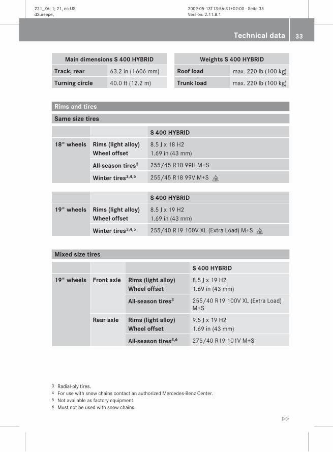
Main dimensions S 400 HYBRID
Track, rear 63.2 in (1 606 mm)
Turning circle 40.0 ft (12.2 m)
Weights S 400 HYBRID
Roof load max. 220 lb (100 kg)
Trunk load max. 220 lb (100 kg)
Rims and tires
Same size tires
S 400 HYBRID
18" wheels Rims (light alloy)Wheel offset
8.5 J x 18 H21.69 in (43 mm)
All-season tires3 255/45 R18 99H M+S
Winter tires3,4,5 255/45 R18 99V M+Si
S 400 HYBRID
19" wheels Rims (light alloy)Wheel offset
8.5 J x 19 H21.69 in (43 mm)
Winter tires3,4,5 255/40 R19 100V XL (Extra Load) M+Si
Mixed size tires
S 400 HYBRID
19" wheels Front axle Rims (light alloy)Wheel offset
8.5 J x 19 H21.69 in (43 mm)
All-season tires3 255/40 R19 100V XL (Extra Load)M+S
Rear axle Rims (light alloy)Wheel offset
9.5 J x 19 H21.69 in (43 mm)
All-season tires3,6 275/40 R19 101V M+S
3 Radial-ply tires.4 For use with snow chains contact an authorized Mercedes-Benz Center.5 Not available as factory equipment.6 Must not be used with snow chains.
Technical data 33
221_ZA; 1; 21, en-USd2ureepe, Version: 2.11.8.1
2009-05-13T13:56:31+02:00 - Seite 33
Z

S 400 HYBRID7
19" wheels Front axle AMG rims (light alloy)Wheel offset
8.5 J x 19 H21.69 in (43 mm)
All-season tires3 255/40 R19 100V XL (Extra Load)M+S
Rear axle AMG rims (light alloy)Wheel offset
9.5 J x 19 H21.69 in (43 mm)
All-season tires3,6 275/40 R19 101V M+S
Spare wheel
S 400 HYBRID
Rim (steel) 4.5 B x 19 H2
Wheel offset 1.38 in (35 mm)
Minispare tire6 T 155/70 R19 113M
Recommended tire inflation pressure 61 psi (4.2 bar)
Capacities
Vehicle components and their respectivelubricants must match. Therefore only useproducts tested and approved by Mercedes-Benz.For information on tested and approvedproducts, contact an authorized Mercedes-Benz Center or visit www.mbusa.com (USAonly).
G Warning!Comply with all valid regulations with respectto handling, storing, and disposing of service
fluids. Otherwise you could endanger personsor the environment.Keep service fluids out of the reach ofchildren.For health reasons, you should preventservice fluids from coming into direct contactwith your skin or clothing.If a service fluid is swallowed, contact aphysician immediately.
7 Vehicles with AMG Sport Package.3 Radial-ply tires.6 Must not be used with snow chains.
34 Technical data
221_ZA; 1; 21, en-USd2ureepe, Version: 2.11.8.1
2009-05-13T13:56:31+02:00 - Seite 34
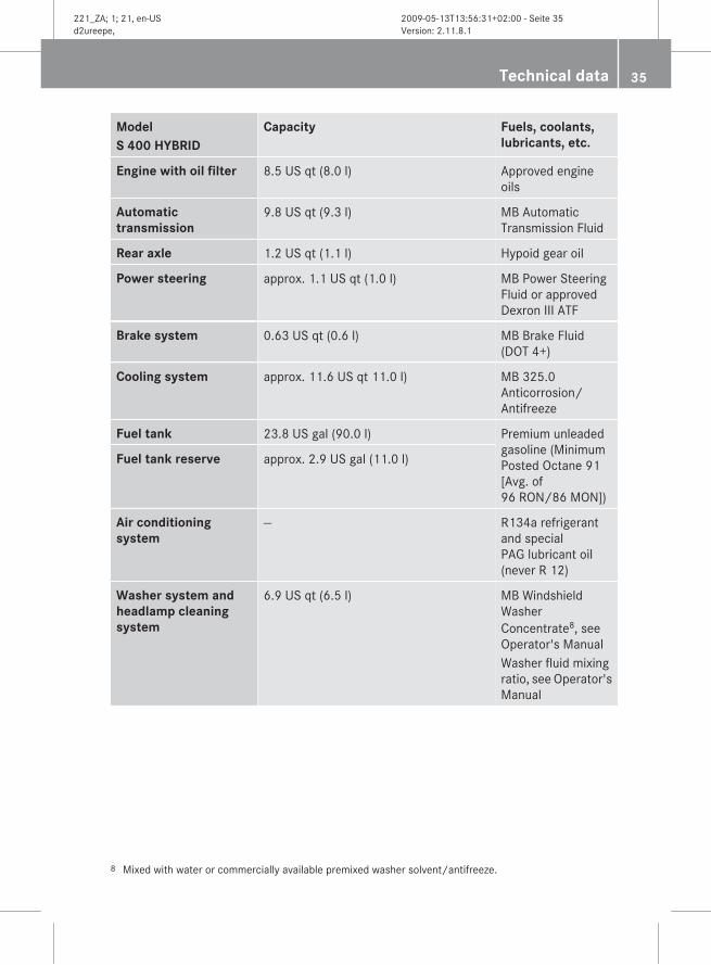
ModelS 400 HYBRID
Capacity Fuels, coolants, lubricants, etc.
Engine with oil filter 8.5 US qt (8.0 l) Approved engineoils
Automatic transmission
9.8 US qt (9.3 l) MB AutomaticTransmission Fluid
Rear axle 1.2 US qt (1.1 l) Hypoid gear oil
Power steering approx. 1.1 US qt (1.0 l) MB Power SteeringFluid or approvedDexron III ATF
Brake system 0.63 US qt (0.6 l) MB Brake Fluid(DOT 4+)
Cooling system approx. 11.6 US qt 11.0 l) MB 325.0Anticorrosion/Antifreeze
Fuel tank 23.8 US gal (90.0 l) Premium unleadedgasoline (MinimumPosted Octane 91[Avg. of96 RON/86 MON])
Fuel tank reserve approx. 2.9 US gal (11.0 l)
Air conditioning system
— R134a refrigerantand specialPAG lubricant oil(never R 12)
Washer system and headlamp cleaning system
6.9 US qt (6.5 l) MB WindshieldWasherConcentrate8, seeOperator's ManualWasher fluid mixingratio, see Operator'sManual
8 Mixed with water or commercially available premixed washer solvent/antifreeze.
Technical data 35
221_ZA; 1; 21, en-USd2ureepe, Version: 2.11.8.1
2009-05-13T13:56:31+02:00 - Seite 35
Z

Approved engine oils Use the table below to determine theMB sheet number.
ModelS 400 HYBRID
Engine,type
MBsheetnumber
272 229.5
i MB sheet numbers are printed on theoutside of oil containers.
i For more information on approved engineoils, refer to the Operator's Manual.
Coolants The engine coolant is a mixture of water andanticorrosion/antifreeze.The cooling system was filled at the factorywith a coolant providing freeze protection toapproximately -35‡ (-37†) and corrosionprotection.
ModelS 400 HYBRID
Approximate freeze protection
-35‡ (-37†) -49‡ (-45†)
Cooling system 5.0 US qt (4.75 l) 5.5 US qt (5.2 l)
! Add premixed coolant solution only.Adding water and MB 325.0 Anticorrosion/Antifreeze separately from each other,could cause engine damage not covered bythe Mercedes-Benz Limited Warranty.
i For more information on coolants, refer tothe Operator's Manual.
36 Technical data
221_ZA; 1; 21, en-USd2ureepe, Version: 2.11.8.1
2009-05-13T13:56:31+02:00 - Seite 36

Service and LiteratureYour authorized Mercedes-Benz Center hastrained technicians and Genuine Mercedes-Benz Parts to service your vehicle properly.For expert advice and quality service, contactan authorized Mercedes-Benz Center.If you are interested in obtaining serviceliterature for your vehicle, please contact anauthorized Mercedes-Benz Center.We consider this the best way for you toobtain accurate information for your vehicle.For further information you can find us on theMercedes-Benz web-site www.mbusa.com(USA only) or www.mercedes-benz.ca(Canada only).
G Warning!To help avoid personal injury, be extremelycareful when performing any service work orrepairs. Improper or incomplete service or theuse of incorrect or inappropriate parts ormaterials may damage the vehicle or itsequipment, which may in turn result inpersonal injury.If you have any questions about carrying outany type of service, turn to the advice of anauthorized Mercedes-Benz Center.
We reserve the right to make changes indesign and equipment.Therefore, information, illustrations anddescriptions in this Supplemental OperatingInstructions might differ from your vehicle.Reprinting, translation and copying, even ofexcerpts, is not permitted without our priorauthorization in writing.Press time May 13, 2009GSP/OISPrinted in U. S. A.
221_ZA; 1; 21, en-USd2ureepe, Version: 2.11.8.1
2009-05-13T13:56:31+02:00 - Seite 37

Order no. 6515 2317 13 Part no. 221 584 48 87 Edition A 2010
É2215844887kËÍ2215844887
221_ZA; 1; 21, en-USd2ureepe, Version: 2.11.8.1
2009-05-13T13:56:31+02:00 - Seite 38