Embed Size (px)
Citation preview
2 STALL
Section Page
2.1 INTRODUCTION ...................................................................................... 2-3
2.2 VEHICLE CONDITION ............................................................................. 2-4
2.3 ACTIVE DDEC DIAGNOSTIC CODES .................................................... 2-7
2.4 LOW FUEL PRESSURE .......................................................................... 2-10
2.5 FUEL SYSTEM ........................................................................................ 2-11
2.6 PSV ASSEMBLY ...................................................................................... 2-15
2.7 FUEL SYSTEM LEARN PROCEDURE ................................................... 2-24

All information subject to change without notice.
2-2 From Bulletin 2-50G/60GTS-03 6SE482 0109 Copyright © 2003 DETROIT DIESEL CORPORATION
SERIES 50G/60G TROUBLESHOOTING MANUAL
2.1 INTRODUCTION
The following section gives procedures to diagnose a natural gas Series 50G or Series 60GDDEC Engine which is stalling.
All information subject to change without notice.6SE482 0109 Copyright © 2003 DETROIT DIESEL CORPORATION From Bulletin 2-50G/60GTS-03 2-3
2.2 VEHICLE CONDITION
2.2 VEHICLE CONDITION
Obvious part and component problems may cause a Stall condition. The first step in diagnosingthe engine is to check related vehicle conditions.
2.2.1 Troubleshooting the Vehicle
To ensure obvious part and component problems are not causing a Stall condition, troubleshootas follows:
1. Check the vehicle controls.
[a] Confirm the vehicle has natural gas in its tanks.
[b] Confirm the batteries are charged.
To avoid injury from an explosion of natural gas, thefollowing precautions must be taken:
Do not smoke when installing or servicing the engineor fuel system.Installation or servicing of natural-gas equipmentmust only be conducted in well-ventilated, natural gascompatible areas. Do not install or service equipmentin an enclosed area where ignition sources are presentwithout first ensuring that an undetected gas leak maybe safely vented without being ignited.Bleed natural gas lines before installing or servicingany component connected to the fuel lines.Natural gas fuel systems are pressurized. Relievepressure from any fuel system component prior toinstallation or service of that component.
Natural gas is highly flammable and explosive and may beextremely cold (-260 F [-162 C]).
[c] Confirm the manual gas valve is open during idle.
[d] If the engine still stalls, go to step 2.
[e] If the engine no longer stalls, troubleshooting is done.
2. Check electrical connections and electronic controls.
[a] Confirm wiring harnesses at DDEC® are connected.
[b] Confirm ground straps from engine to starter are connected.
[c] Confirm wire 439 in DDEC power harness is not loose.
[d] Confirm the PLC/Multiplex/Electrical System is getting power.
All information subject to change without notice.
2-4 From Bulletin 2-50G/60GTS-03 6SE482 0109 Copyright © 2003 DETROIT DIESEL CORPORATION
SERIES 50G/60G TROUBLESHOOTING MANUAL
[e] Confirm proper operation of the fire suppression system and the methane detectionsystem. Refer to OEM Vehicle Manual.
[f] Confirm all coils are receiving 12 V during cranking and idle. If not receiving 12 Vat coils, troubleshoot vehicle electrical system. Refer to OEM Vehicle Manual.
[g] Confirm proper operation of all tank valves and high pressure solenoid valve duringcranking. Refer to OEM Vehicle Manual.
[h] Confirm proper operation of the Stop Engine Light (SEL).
[i] Confirm proper operation of the Check Engine Light (CEL).
To avoid injury from an explosion of natural gas, thefollowing precautions must be taken:
Do not smoke when installing or servicing the engineor fuel system.Installation or servicing of natural-gas equipmentmust only be conducted in well-ventilated, natural gascompatible areas. Do not install or service equipmentin an enclosed area where ignition sources are presentwithout first ensuring that an undetected gas leak maybe safely vented without being ignited.Bleed natural gas lines before installing or servicingany component connected to the fuel lines.Natural gas fuel systems are pressurized. Relievepressure from any fuel system component prior toinstallation or service of that component.
Natural gas is highly flammable and explosive and may beextremely cold (-260 F [-162 C]).
[j] If the engine still stalls, go to step 3.
[k] If the engine no longer stalls, troubleshooting is done.
3. Check the installation requirements for the electronic system.
[a] Verify the installation requirements for the electronic system have been met.Refer to section 8. If the engine installation requirements for the electronic systemdid not comply, repair as required.
All information subject to change without notice.6SE482 0109 Copyright © 2003 DETROIT DIESEL CORPORATION From Bulletin 2-50G/60GTS-03 2-5
2.2 VEHICLE CONDITION
To avoid injury from an explosion of natural gas, thefollowing precautions must be taken:
Do not smoke when installing or servicing the engineor fuel system.Installation or servicing of natural-gas equipmentmust only be conducted in well-ventilated, natural gascompatible areas. Do not install or service equipmentin an enclosed area where ignition sources are presentwithout first ensuring that an undetected gas leak maybe safely vented without being ignited.Bleed natural gas lines before installing or servicingany component connected to the fuel lines.Natural gas fuel systems are pressurized. Relievepressure from any fuel system component prior toinstallation or service of that component.
Natural gas is highly flammable and explosive and may beextremely cold (-260 F [-162 C]).
[b] If the engine still stalls, check the active DDEC diagnostic codes. Refer to section 2.3.
[c] If the engine no longer stalls, troubleshooting is done.
All information subject to change without notice.
2-6 From Bulletin 2-50G/60GTS-03 6SE482 0109 Copyright © 2003 DETROIT DIESEL CORPORATION
SERIES 50G/60G TROUBLESHOOTING MANUAL
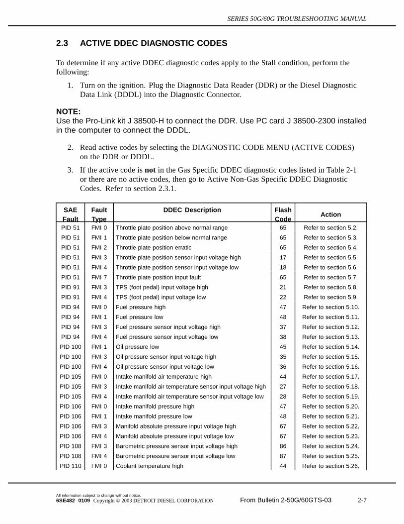
2.3 ACTIVE DDEC DIAGNOSTIC CODES
To determine if any active DDEC diagnostic codes apply to the Stall condition, perform thefollowing:
1. Turn on the ignition. Plug the Diagnostic Data Reader (DDR) or the Diesel DiagnosticData Link (DDDL) into the Diagnostic Connector.
NOTE:Use the Pro-Link kit J 38500-H to connect the DDR. Use PC card J 38500-2300 installedin the computer to connect the DDDL.
2. Read active codes by selecting the DIAGNOSTIC CODE MENU (ACTIVE CODES)on the DDR or DDDL.
3. If the active code is not in the Gas Specific DDEC diagnostic codes listed in Table 2-1or there are no active codes, then go to Active Non-Gas Specific DDEC DiagnosticCodes. Refer to section 2.3.1.
SAEFault
FaultType
DDEC Description FlashCode
Action
PID 51 FMI 0 Throttle plate position above normal range 65 Refer to section 5.2.
PID 51 FMI 1 Throttle plate position below normal range 65 Refer to section 5.3.
PID 51 FMI 2 Throttle plate position erratic 65 Refer to section 5.4.
PID 51 FMI 3 Throttle plate position sensor input voltage high 17 Refer to section 5.5.
PID 51 FMI 4 Throttle plate position sensor input voltage low 18 Refer to section 5.6.
PID 51 FMI 7 Throttle plate position input fault 65 Refer to section 5.7.
PID 91 FMI 3 TPS (foot pedal) input voltage high 21 Refer to section 5.8.
PID 91 FMI 4 TPS (foot pedal) input voltage low 22 Refer to section 5.9.
PID 94 FMI 0 Fuel pressure high 47 Refer to section 5.10.
PID 94 FMI 1 Fuel pressure low 48 Refer to section 5.11.
PID 94 FMI 3 Fuel pressure sensor input voltage high 37 Refer to section 5.12.
PID 94 FMI 4 Fuel pressure sensor input voltage low 38 Refer to section 5.13.
PID 100 FMI 1 Oil pressure low 45 Refer to section 5.14.
PID 100 FMI 3 Oil pressure sensor input voltage high 35 Refer to section 5.15.
PID 100 FMI 4 Oil pressure sensor input voltage low 36 Refer to section 5.16.
PID 105 FMI 0 Intake manifold air temperature high 44 Refer to section 5.17.
PID 105 FMI 3 Intake manifold air temperature sensor input voltage high 27 Refer to section 5.18.
PID 105 FMI 4 Intake manifold air temperature sensor input voltage low 28 Refer to section 5.19.
PID 106 FMI 0 Intake manifold pressure high 47 Refer to section 5.20.
PID 106 FMI 1 Intake manifold pressure low 48 Refer to section 5.21.
PID 106 FMI 3 Manifold absolute pressure input voltage high 67 Refer to section 5.22.
PID 106 FMI 4 Manifold absolute pressure input voltage low 67 Refer to section 5.23.
PID 108 FMI 3 Barometric pressure sensor input voltage high 86 Refer to section 5.24.
PID 108 FMI 4 Barometric pressure sensor input voltage low 87 Refer to section 5.25.
PID 110 FMI 0 Coolant temperature high 44 Refer to section 5.26.
All information subject to change without notice.6SE482 0109 Copyright © 2003 DETROIT DIESEL CORPORATION From Bulletin 2-50G/60GTS-03 2-7
2.3 ACTIVE DDEC DIAGNOSTIC CODES
SAEFault
FaultType
DDEC Description FlashCode
Action
PID 110 FMI 3 The coolant temperature sensor input voltage is high 14 Refer to section 5.27.
PID 110 FMI 4 Coolant temperature sensor input voltage low 15 Refer to section 5.28.
PID 111 FMI 1 Coolant level low 43 Refer to section 5.29.
PID 111 FMI 3 Coolant level sensor input voltage high 16 Refer to section 5.30.
PID 111 FMI 4 Coolant level sensor input voltage low 13 Refer to section 5.31.
PID 173 FMI 3 Exhaust temperature sensor input voltage high 81 Refer to section 5.32.
PID 173 FMI 4 Exhaust temperature sensor input voltage low 82 Refer to section 5.33.
PID 174 FMI 3 Fuel temperature sensor input voltage high 23 Refer to section 5.34.
PID 174 FMI 4 Fuel temperature sensor input voltage low 24 Refer to section 5.35.
SID 21 FMI 0 Too many SRS (missing TRS) 41 Refer to section 6.2.
SID 21 FMI 1 Too few SRS (missing TRS) 42 Refer to section 6.3.
SID 51 FMI 3 Aux. output No. 3, short to ground (high side) 31 Refer to section 6.4.
SID 58 FMI 4 PWM driver No. 2 open circuit 63 Refer to section 6.5.
SID 59 FMI 3 PWM driver No. 3 short to battery (+) 63 Refer to section 6.6.
SID 59 FMI 4 PWM driver No. 3 open circuit 63 Refer to section 6.7.
SID 65 FMI 3 Oxygen content circuit voltage high 23 Call Detroit DieselTechnical Service.
SID 65 FMI 4 Oxygen content circuit voltage low 24 Call Detroit DieselTechnical Service.
SID 76 FMI 0 Engine knock level above normal range 66 Refer to section 6.8.
SID 76 FMI 3 Engine knock level sensor input voltage high 66 Refer to section 6.9.
SID 76 FMI 4 Engine knock level sensor input low 66 Refer to section 6.10.
SID 76 FMI 7 Engine knock level torque reduction 66 Refer to section 6.11.
SID 77 FMI 3 Gas Valve Position input voltage high 73 Refer to section 6.12.
SID 77 FMI 4 Gas Valve Position input voltage low 73 Refer to section 6.13.
SID 232 FMI 0 Sensor supply voltage high 75 Refer to section 6.14.
SID 232 FMI 1 Sensor supply voltage low 46 Refer to section 6.15.
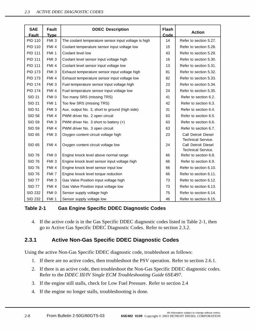
Table 2-1 Gas Engine Specific DDEC Diagnostic Codes
4. If the active code is in the Gas Specific DDEC diagnostic codes listed in Table 2-1, thengo to Active Gas Specific DDEC Diagnostic Codes. Refer to section 2.3.2.
2.3.1 Active Non-Gas Specific DDEC Diagnostic Codes
Using the active Non-Gas Specific DDEC diagnostic code, troubleshoot as follows:
1. If there are no active codes, then troubleshoot the PSV operation. Refer to section 2.6.1.
2. If there is an active code, then troubleshoot the Non-Gas Specific DDEC diagnostic codes.Refer to the DDEC III/IV Single ECM Troubleshooting Guide 6SE497.
3. If the engine still stalls, check for Low Fuel Pressure. Refer to section 2.4
4. If the engine no longer stalls, troubleshooting is done.
All information subject to change without notice.
2-8 From Bulletin 2-50G/60GTS-03 6SE482 0109 Copyright © 2003 DETROIT DIESEL CORPORATION
SERIES 50G/60G TROUBLESHOOTING MANUAL
2.3.2 Active Gas Specific DDEC Diagnostic Codes
Using the active Gas Specific DDEC diagnostic code, troubleshoot as follows:
1. If there is a Low Fuel Pressure code (PID 94 FMI 1), then check for low fuel pressure.Refer to section 2.4.
2. If there is a Gas Valve Position code (SID 77 FMI 0, SID 77 FMI 1, SID 77 FMI 3, SID 77FMI 4, SID 77 FMI 7), then troubleshoot the PSV operation. Refer to section 2.6.1.
3. If there are any other active Gas Engine Specific DDEC diagnostic codeslisted in Table 2-1, then troubleshoot the code referenced in the table.
4. If the engine still stalls, check for Low Fuel Pressure. Refer to section 2.4.
5. If the engine no longer stalls, troubleshooting is done.
All information subject to change without notice.6SE482 0109 Copyright © 2003 DETROIT DIESEL CORPORATION From Bulletin 2-50G/60GTS-03 2-9
2.4 LOW FUEL PRESSURE
2.4 LOW FUEL PRESSURE
Check for Low Fuel Pressure causing a Stall condition as follows:
To avoid injury from an explosion of natural gas, thefollowing precautions must be taken:
Do not smoke when installing or servicing the engineor fuel system.Installation or servicing of natural-gas equipmentmust only be conducted in well-ventilated, natural gascompatible areas. Do not install or service equipmentin an enclosed area where ignition sources are presentwithout first ensuring that an undetected gas leak maybe safely vented without being ignited.Bleed natural gas lines before installing or servicingany component connected to the fuel lines.Natural gas fuel systems are pressurized. Relievepressure from any fuel system component prior toinstallation or service of that component.
Natural gas is highly flammable and explosive and may beextremely cold (-260 F [-162 C]).
1. Turn the ignition on, crank the engine over, and check the DDR or DDDL for fuel pressure.
2. If the fuel pressure is above 94 psia (649 kPa-a) (CNG) or above 74 psia (511 kPa-a)(LNG), then troubleshoot the PSV operation. Refer to section 2.6.1.
3. If there is no fuel pressure or the fuel pressure is below 94 psia (649 kPa-a) (CNG) or74 psia (511 kPa-a) (LNG), then check the operation of the Low Pressure Fuel Shut-OffValve. Refer to section 2.5.1.
4. If the engine still stalls, check the Fuel System. Refer to section 2.5.
5. If the engine no longer stalls, troubleshooting is done.
All information subject to change without notice.
2-10 From Bulletin 2-50G/60GTS-03 6SE482 0109 Copyright © 2003 DETROIT DIESEL CORPORATION
SERIES 50G/60G TROUBLESHOOTING MANUAL
2.5 FUEL SYSTEM
The Series 50G or Series 60G DDEC Engine Fuel System consist of the Low Pressure FuelShut-Off Valve, the fuel line, and primary and secondary Fuel Filters.
2.5.1 Low Pressure Fuel Shut-Off Valve Check
Check the Low Pressure Fuel Shut-Off Valve power during cranking as follows:
1. Turn on the ignition.
To avoid injury from an explosion of natural gas, thefollowing precautions must be taken:
Do not smoke when installing or servicing the engineor fuel system.Installation or servicing of natural-gas equipmentmust only be conducted in well-ventilated, natural gascompatible areas. Do not install or service equipmentin an enclosed area where ignition sources are presentwithout first ensuring that an undetected gas leak maybe safely vented without being ignited.Bleed natural gas lines before installing or servicingany component connected to the fuel lines.Natural gas fuel systems are pressurized. Relievepressure from any fuel system component prior toinstallation or service of that component.
Natural gas is highly flammable and explosive and may beextremely cold (-260 F [-162 C]).
2. Crank the engine over.
3. During cranking, check the T3 output using the DDR.
[a] If DDR or DDDL indicates T3 output is “ON”, go to step 4.
[b] If DDR or DDDL indicates T3 output is “OFF”, then verify with a voltmeter thatwire 562 (orange) voltage is 12 or 24 V (as electrical system requires) at the ECM.
[c] If wire 562 (orange, T3 output) voltage is below 12 or 24 V (as electrical systemrequires), the replace the ECM.
4. During cranking, check voltage at solenoid with a voltmeter.
[a] If voltage is below 12 or 24 V (as electrical system requires), then check the vehiclewiring. Refer to OEM Vehicle Manual.
[b] If voltage is 12 or 24 V (as electrical system requires), then check the solenoidfor clicking during cranking.
All information subject to change without notice.6SE482 0109 Copyright © 2003 DETROIT DIESEL CORPORATION From Bulletin 2-50G/60GTS-03 2-11
2.5 FUEL SYSTEM
[c] If there is no clicking, then depressurize Fuel System (refer to section 2.5.2),replace the Low Pressure Fuel Shut-Off Valve, and leak check the Fuel System(refer to section 2.5.4).
[d] If there is clicking, then depressurize Fuel System (refer to section 2.5.2) and checkthe Fuel Filters (refer to section 2.5.3).
2.5.2 Depressurization of the Fuel System
Vent the natural gas pressure downstream of the shutoff valve as follows:
To avoid injury from an explosion of natural gas, thefollowing precautions must be taken:
Do not smoke when installing or servicing the engineor fuel system.Installation or servicing of natural-gas equipmentmust only be conducted in well-ventilated, natural gascompatible areas. Do not install or service equipmentin an enclosed area where ignition sources are presentwithout first ensuring that an undetected gas leak maybe safely vented without being ignited.Bleed natural gas lines before installing or servicingany component connected to the fuel lines.Natural gas fuel systems are pressurized. Relievepressure from any fuel system component prior toinstallation or service of that component.
Natural gas is highly flammable and explosive and may beextremely cold (-260 F [-162 C]).
1. Shut off the manual valves on the natural gas supply tanks and main shutoff valve onnatural gas fuel supply line.
2. Disconnect vehicle batteries using switch(es) in battery compartment or by disconnectingthe battery ground cable.
3. Ensure gage pressure at point on the natural gas fuel line to be vented has been reducedto zero. If gage pressure not zero, repeat steps 1 and 2.
4. Slightly loosen the CNG or LNG fuel line fitting to be serviced in a well-ventilatedarea to allow any remaining gas to vent.
5. Completely open the fitting that was slightly opened and allow to vent in a well-ventilatedarea.
All information subject to change without notice.
2-12 From Bulletin 2-50G/60GTS-03 6SE482 0109 Copyright © 2003 DETROIT DIESEL CORPORATION
SERIES 50G/60G TROUBLESHOOTING MANUAL
2.5.3 Inspection of the Fuel System
Inspect the Fuel System as follows:
1. Remove the primary and secondary Fuel Filters. Inspect for contamination or residueplugging the inside of the filter.
[a] If the primary or secondary Fuel Filter is contaminated or plugged with residue,replace with a new filter element.
[b] If not contaminated, reinstall the filter element.
2. Remove the Low Pressure Fuel Shut-Off Valve and inspect for a blocked passageway.
[a] If the valve is plugged with residue, replace with a new Low Pressure Fuel Shut-OffValve.
[b] If not plugged, reinstall the Low Pressure Fuel Shut-Off Valve.
3. Disconnect the fuel line and inspect for a blocked passageway.
[a] If the fuel line is plugged with residue, clear fuel line or replace with a new fuel line.
[b] If not plugged, reconnect the fuel line.
2.5.4 Leak Check of the Fuel System
Leak check the Fuel System as follows:
All information subject to change without notice.6SE482 0109 Copyright © 2003 DETROIT DIESEL CORPORATION From Bulletin 2-50G/60GTS-03 2-13
2.5 FUEL SYSTEM
To avoid injury from an explosion of natural gas, thefollowing precautions must be taken:
Do not smoke when installing or servicing the engineor fuel system.Installation or servicing of natural-gas equipmentmust only be conducted in well-ventilated, natural gascompatible areas. Do not install or service equipmentin an enclosed area where ignition sources are presentwithout first ensuring that an undetected gas leak maybe safely vented without being ignited.Bleed natural gas lines before installing or servicingany component connected to the fuel lines.Natural gas fuel systems are pressurized. Relievepressure from any fuel system component prior toinstallation or service of that component.
Natural gas is highly flammable and explosive and may beextremely cold (-260 F [-162 C]).
1. Spray soapy water or commercially available leak checking solutions on connectionswhich are pressurized to working pressure. Look for bubbles indicating there is a leak.
2. Repair any leak found by:
[a] Tightening connection using the fitting manufacture's recommended technique.
[b] Replacing leaking component.
[c] Replace the pipe threaded connector with a new one. If the leak is a pipe threadconnection, use anaerobic sealant with Teflon® (such as SWAK®) applied to thethreads.
Teflon® is a registered trademark of E.I. DuPont de Nemours and Company, Inc. SWAK® is aregistered trademark of Cajon Company
3. Recheck connections with the procedures in steps 1 and 2.
4. Use a combustible gas detector to check for the presence of natural gas. If natural gas isdetected, continue looking for leaks until the locations of all the leaks are determined.
5. If the engine still stalls, check the PSV assembly. Refer to section 2.6.
6. If the engine no longer stalls, troubleshooting is done.
All information subject to change without notice.
2-14 From Bulletin 2-50G/60GTS-03 6SE482 0109 Copyright © 2003 DETROIT DIESEL CORPORATION
SERIES 50G/60G TROUBLESHOOTING MANUAL
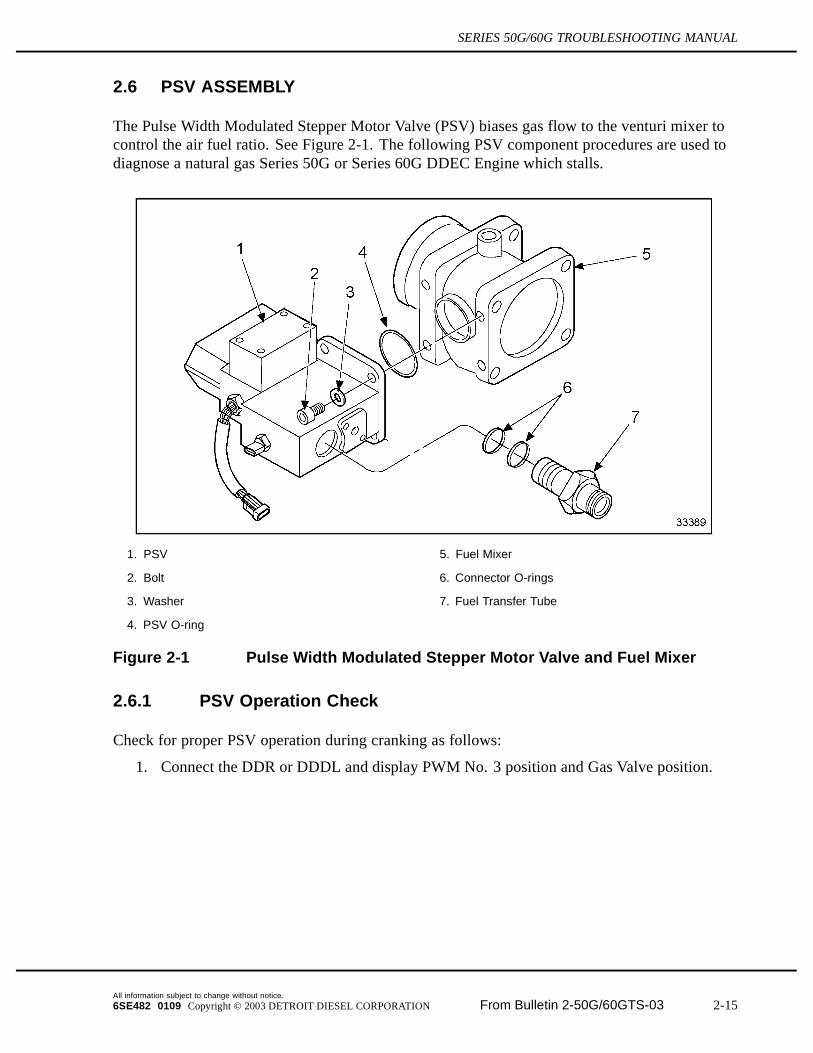
2.6 PSV ASSEMBLY
The Pulse Width Modulated Stepper Motor Valve (PSV) biases gas flow to the venturi mixer tocontrol the air fuel ratio. See Figure 2-1. The following PSV component procedures are used todiagnose a natural gas Series 50G or Series 60G DDEC Engine which stalls.
1. PSV 5. Fuel Mixer
2. Bolt 6. Connector O-rings
3. Washer 7. Fuel Transfer Tube
4. PSV O-ring
Figure 2-1 Pulse Width Modulated Stepper Motor Valve and Fuel Mixer
2.6.1 PSV Operation Check
Check for proper PSV operation during cranking as follows:
1. Connect the DDR or DDDL and display PWM No. 3 position and Gas Valve position.
All information subject to change without notice.6SE482 0109 Copyright © 2003 DETROIT DIESEL CORPORATION From Bulletin 2-50G/60GTS-03 2-15
2.6 PSV ASSEMBLY
To avoid injury from an explosion of natural gas, thefollowing precautions must be taken:
Do not smoke when installing or servicing the engineor fuel system.Installation or servicing of natural-gas equipmentmust only be conducted in well-ventilated, natural gascompatible areas. Do not install or service equipmentin an enclosed area where ignition sources are presentwithout first ensuring that an undetected gas leak maybe safely vented without being ignited.Bleed natural gas lines before installing or servicingany component connected to the fuel lines.Natural gas fuel systems are pressurized. Relievepressure from any fuel system component prior toinstallation or service of that component.
Natural gas is highly flammable and explosive and may beextremely cold (-260 F [-162 C]).
2. Crank the engine and read PWM No. 3 position and Gas Valve position.
3. If PWM No. 3 position indicates 26–50 % andGas Valve position indicates 50–80 % butthe engine still stalls, then replace the low pressure regulator. Refer to section 2.6.3.
4. If PWM No. 3 position indicates 26–50 % and Gas Valve position is not moving, thencheck the PSV power and PWM No. 3 output as follows:
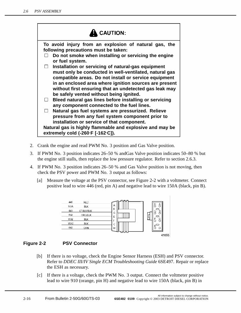
[a] Measure the voltage at the PSV connector, see Figure 2-2 with a voltmeter. Connectpositive lead to wire 446 (red, pin A) and negative lead to wire 150A (black, pin B).
Figure 2-2 PSV Connector
[b] If there is no voltage, check the Engine Sensor Harness (ESH) and PSV connector.Refer to DDEC III/IV Single ECM Troubleshooting Guide 6SE497. Repair or replacethe ESH as necessary.
[c] If there is a voltage, check the PWM No. 3 output. Connect the voltmeter positivelead to wire 910 (orange, pin H) and negative lead to wire 150A (black, pin B) in
All information subject to change without notice.
2-16 From Bulletin 2-50G/60GTS-03 6SE482 0109 Copyright © 2003 DETROIT DIESEL CORPORATION
SERIES 50G/60G TROUBLESHOOTING MANUAL
PSV connector, see Figure 2-2. With the DDR or DDDL, slew the PWM No. 3output from 10 % to 50 % and then to 90 %.
[d] If there is a change in voltage, then troubleshoot the PSV assembly,refer to section 2.6.2.
[e] If there is no change in voltage, then troubleshoot the ESH and PSV connector. Referto DDEC III/IV Single ECM Troubleshooting Guide 6SE497. Repair or replacethe ESH as necessary.
5. If PWM No. 3 does not move, check for voltage using a voltmeter. Connect the positivelead to wire 446 (red, pin A) and negative lead to 910 (orange, pin H), see Figure 2-2.
[a] If there is no voltage, replace the ECM and then follow the Fuel System LearnProcedure. Refer to section 2.7.
[b] If there is a voltage, then troubleshoot the PSV assembly, refer to section 2.6.2.
6. If the gas valve does not move from 0 %, check the voltage using a voltmeter. Connectpositive lead to wire 446 (red, pin A) and negative lead to wire 150A (black, pin B) of thePSV connector, see Figure 2-2.
[a] If there is a voltage at the PSV connector, then troubleshoot the PSV assembly,refer to section 2.6.2.
[b] If there is no voltage, then troubleshoot the ESH, PSV connector, and. the OEMpower harness. Refer to DDEC III/IV Single ECM Troubleshooting Guide 6SE497.Repair or replace the ESH and the OEM power harness as necessary.
7. If the Gas Valve position moves but appears to have sluggish or erratic movement, checkvoltage at the PSV connector with a voltmeter. Connect positive lead to wire 446 (red, pinA) and negative lead to wire 150A (black, pin B), see Figure 2-2.
[a] If there is less than 10 volts, charge the batteries.
[b] If 10-12 volts are present during cranking, then troubleshoot the PSV assembly,refer to section 2.6.2.
2.6.2 PSV Assembly Troubleshooting
Troubleshoot the PSV assembly as follows:
1. Remove PSV from engine. Do not unplug electronic connector.
2. Remove 13 mm plug and install digital dial indicator (Mitutoyo® Digimatic Indicator,part No. 575-123 or equivalent).
Mitutoyo® is a registered trademark of Mitutoyo Manufacturing Co., LTD.
3. Plug in DDR or DDDL and go to activate outputs. Input 0 % PWM to PWM No. 3.
4. Set digital indicator to 0 mm (0 in.).
All information subject to change without notice.6SE482 0109 Copyright © 2003 DETROIT DIESEL CORPORATION From Bulletin 2-50G/60GTS-03 2-17
2.6 PSV ASSEMBLY
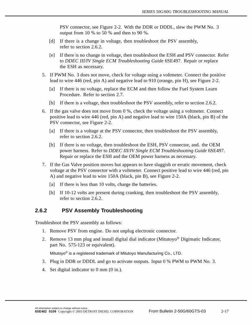
5. Input values listed in Table 2-2 from column 1 to PWM No. 3 with the DDR or DDDL.
PWM No. 3 Reading Programmed Travel Travel Limits0 % 0 mm (0 in.)
10 % 1 mm (0.04 in.) 0.9–1.1 mm (0.035–0.043 in.)
50 % 5 mm (0.20 in.) 4.9–5.1 mm (0.193–0.201 in.)
100 % 10 mm (0.39 in.) 9.9–10.1 mm (0.390–0.398 in.)
Column 2 shows the programmed travel and column 3 shows the limits of acceptable travel.
Table 2-2 PWM No. 3 Input and Acceptable Travel
6. If the PSV assembly shows any of the following failure modes, then replace thePSV assembly (refer to section 2.6.3), and perform the Fuel System Learn Procedure(refer to section 2.7).
[a] PSV remains at or below approximately 50 % of travel.
[b] PSV piston does not move (indicator reads zero throughout).
[c] PSV moves slowly or does not move to the value listed in Table 2-2, Column 3.
[d] PSV exhibits erratic operation.
7. If engine no longer stalls, troubleshooting is complete.
2.6.3 Replacing the Throttle
Use the bolt loosening and tightening sequences and the throttle assembly procedure in thefollowing sections when replacing the throttle. Refer to section 2.6.3.1 for the bolt loosening andtightening sequences and refer to section 2.6.3.2 for the throttle assembly procedure.
2.6.3.1 Bolt Tightening Sequence
Loosen the bolts using the following sequence.
1. Loosen the four bolts that attach the intake elbow to the rear of the throttle.
2. Loosen the four bolts that attach the Mixer/PSV assembly to the front of the throttle.
3. Loosen the two bolts that attach the low pressure regulator to the intake elbow.
4. Loosen the four bolts that attach the throttle to the throttle bracket.
Tighten all the bolts using the following sequence:
NOTE:Torque for all bolts is 34 N·m (25 ft·lb).
1. Tighten the two bolts from the throttle bracket to the gear case.
2. Tighten the one bolt from the throttle bracket to the cylinder head.
All information subject to change without notice.
2-18 From Bulletin 2-50G/60GTS-03 6SE482 0109 Copyright © 2003 DETROIT DIESEL CORPORATION
SERIES 50G/60G TROUBLESHOOTING MANUAL
3. Tighten the four bolts from the Mixer/PSV assembly to the throttle.
4. Tighten the four bolts from the throttle to the inlet elbow.
5. Tighten the two bolts from the low pressure regulator.
6. Tighten the two bolts from the throttle bracket to the inlet elbow.
7. Tighten the four bolts from the bottom of the throttle bracket to the throttle.
2.6.3.2 Throttle Assembly Procedure
Replace the throttle assembly as follows:
All information subject to change without notice.6SE482 0109 Copyright © 2003 DETROIT DIESEL CORPORATION From Bulletin 2-50G/60GTS-03 2-19
2.6 PSV ASSEMBLY
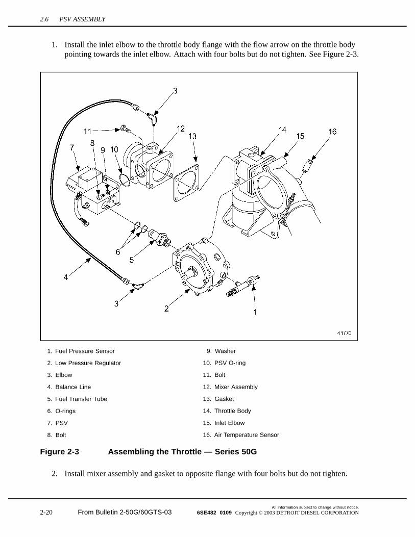
1. Install the inlet elbow to the throttle body flange with the flow arrow on the throttle bodypointing towards the inlet elbow. Attach with four bolts but do not tighten. See Figure 2-3.
1. Fuel Pressure Sensor 9. Washer
2. Low Pressure Regulator 10. PSV O-ring
3. Elbow 11. Bolt
4. Balance Line 12. Mixer Assembly
5. Fuel Transfer Tube 13. Gasket
6. O-rings 14. Throttle Body
7. PSV 15. Inlet Elbow
8. Bolt 16. Air Temperature Sensor
Figure 2-3 Assembling the Throttle — Series 50G
2. Install mixer assembly and gasket to opposite flange with four bolts but do not tighten.
All information subject to change without notice.
2-20 From Bulletin 2-50G/60GTS-03 6SE482 0109 Copyright © 2003 DETROIT DIESEL CORPORATION
SERIES 50G/60G TROUBLESHOOTING MANUAL
3. Attach the PSV and O-ring to the mixer with four Allen head screws but do not tighten.
4. Lubricate O-rings used with fuel transfer tube with Lubriplate® prior to assembly.
Lubriplate® is a registered trademark of Fiske Brothers Refining Company.
5. Install O-rings to fuel transfer tube. Apply Teflon® liquid pipe sealant to threads.
6. Thread fuel transfer tube into regulator and tighten.
NOTE:The fuel transfer tube must thread into the regulator just far enough so the O-ring sealdoes not bottom out in the PSV valve and cut the seal when the regulator is boltedto the inlet elbow.
7. Install the low pressure regulator and fuel transfer tube into the PSV. Bolt regulator to inletelbow with two bolts but do not tighten.
All information subject to change without notice.6SE482 0109 Copyright © 2003 DETROIT DIESEL CORPORATION From Bulletin 2-50G/60GTS-03 2-21
2.6 PSV ASSEMBLY
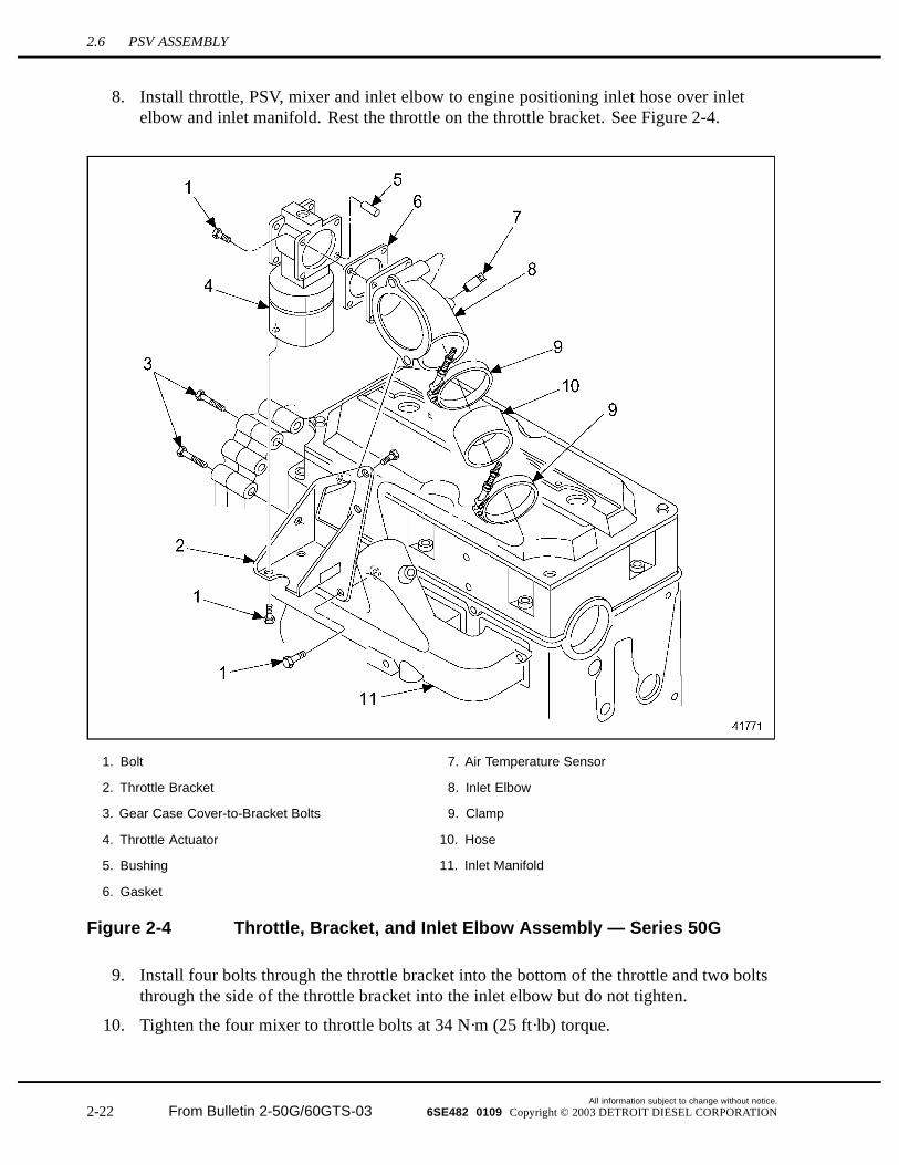
8. Install throttle, PSV, mixer and inlet elbow to engine positioning inlet hose over inletelbow and inlet manifold. Rest the throttle on the throttle bracket. See Figure 2-4.
1. Bolt 7. Air Temperature Sensor
2. Throttle Bracket 8. Inlet Elbow
3. Gear Case Cover-to-Bracket Bolts 9. Clamp
4. Throttle Actuator 10. Hose
5. Bushing 11. Inlet Manifold
6. Gasket
Figure 2-4 Throttle, Bracket, and Inlet Elbow Assembly — Series 50G
9. Install four bolts through the throttle bracket into the bottom of the throttle and two boltsthrough the side of the throttle bracket into the inlet elbow but do not tighten.
10. Tighten the four mixer to throttle bolts at 34 N·m (25 ft·lb) torque.
All information subject to change without notice.
2-22 From Bulletin 2-50G/60GTS-03 6SE482 0109 Copyright © 2003 DETROIT DIESEL CORPORATION
SERIES 50G/60G TROUBLESHOOTING MANUAL
11. Tighten the four throttle to inlet elbow bolts at 34 N·m (25 ft·lb) torque.
12. Tighten the two bolts that hold the regulator to the inlet elbow and tighten the four screwsthat hold the PSV to the mixer.
13. Adjust the two bolts through the throttle bracket to the inlet elbow and the four boltsthrough the bottom of the throttle bracket to the throttle alternatively to ensure that there isno bind in the throttle. Torque the two brackets to the inlet elbow bolts at 34 N·m (25 ft·lb)and the four throttle mounting bolts at 34 N·m (25 ft·lb).
All information subject to change without notice.6SE482 0109 Copyright © 2003 DETROIT DIESEL CORPORATION From Bulletin 2-50G/60GTS-03 2-23
2.7 FUEL SYSTEM LEARN PROCEDURE
2.7 FUEL SYSTEM LEARN PROCEDURE
Fill in the AFR table for the Fuel System follows:
NOTE:Use a chassis dynamometer to apply loads to the engine whenever appropriate as analternative to on-highway vehicle operation.
1. Fill in the AFR table values from idle to No Load speed for the unloaded portion asfollows:
[a] Reset the AFR table with the DDR or DDDL.
[b] Slowly increase the engine speed from idle to No Load (0–100 % throttle) and thenslowly decrease the speed back to idle (100–0 % throttle) over one minute.
[c] Repeat step 1[b] two times.
2. Fill in the AFR table values from idle to stall speed for the loaded portion as follows:
[a] With an applied load, slowly increase the engine speed from idle to stall speed(0–100 % throttle) and then slowly decrease the speed back to idle (100–0 % throttle)over one minute.
[b] Repeat step 2[a] two times.
3. Fill in the AFR table above the stall speed for the unloaded portion as follows:
NOTE:The engine must operate in this speed/boost range for a moderate length of time. TheAFR table will not completely fill in just passing through this range.
NOTE:The best method to apply a load through stall speed to 2100 RPM is to drive the vehicleup a hill, locked into a lower gear to prevent transmission shifting. If a hill is not available,lock the vehicle in low gear and accelerate from a stop to 2100 RPM full load.
[a] Slowly operate the engine from stall speed to 2100 RPM with an applied load.
[b] Repeat step 3[a] until the engine runs smooth through this speed range.
4. Road test the vehicle as follows:
[a] Operate the engine through a variety of speed and loads while looking for anymisfires.
[b] If a particular RPM/Manifold pressure range still experiences misfire, then operatethe engine around that point by running through that range slowly.
[c] Repeat step 4[a] and step 4[b] until the engine runs smooth without any lean misfires.A smooth running engine means the Fuel System Learn Procedure is complete.
All information subject to change without notice.
2-24 From Bulletin 2-50G/60GTS-03 6SE482 0109 Copyright © 2003 DETROIT DIESEL CORPORATION


![Untitled-1 [jmacfiles.s3.amazonaws.com] · Guia de Instalação em Português Eestikeelse paigaldusjuhendi TE100-S50g TE100-S50g(V2) / 04.18.2013 ... 1 año de garantía para componentes](https://img.pdfslide.net/doc/110x75/5c1ee6b909d3f25d2e8be01e/untitled-1-jmacfiless3-guia-de-instalacao-em-portugues-eestikeelse-paigaldusjuhendi.jpg)

![A1035AS-PL Sp. z o.o. Product card: A1035 4 Brand Model Type Year Comments FREIGHTLINER FLD112 [C13] 01.2003-FREIGHTLINER FLD112 [C13] 01.2004-FREIGHTLINER FLD112 [C13] 01.2005-FREIGHTLINER](https://img.pdfslide.net/doc/110x75/60c90a435c61a6413c17c9aa/a1035-as-pl-sp-z-oo-product-card-a1035-4-brand-model-type-year-comments-freightliner.jpg)