Embed Size (px)
Citation preview

SA85 Modbus Plus Host Interface Adapter
Device Driver for OpenVMS/AXP
Release: 3.0
Integrated Process Automation &Control Technologies

19-Aug-99
Copyright 1997 by: Integrated Process Automation and Control Technologies Incorporated
All rights reserved. No part of this publication may be reproduced, stored in a retrieval system, ortransmitted in any form without written permission from IPACT Inc.
Technical Writer:Earl D. LakiaSenior Staff EngineerIPACT Inc.This document is also a condensation and merging of the following two documents: Modicon DEC HostBased Devices User’s Guide and Modicon IBM Host Based Devices User’s Guide. Published by Modicon,Inc. Industrial Automation Systems.
This document is the property of and is proprietary to Integrated Process Automation and ControlTechnologies (IPACT). The information in this document is subject to change without notice andshould not be construed as a commitment by IPACT. IPACT assumes no responsibility for anyerrors that may appear in this document.
The software described in this document is furnished under a license and may be used or copiedonly in accordance with the terms of such a license.
Integrated Process Automation and Control Technologies makes no representations that the use ofits products in the manner described in this publication will not infringe on existing or future patentrights, nor do the descriptions contained in this publication imply the granting of licenses to make,use, or sell equipment or software in accordance with the description.
Copyright © 1999 by Integrated Process Automation and Control TechnologiesAll Rights ReservedUSA
The data furnished in this document is subject to the terms of the copyright page and remain theproperty of IPACT Inc. No part of this document or included distribution media shall beduplicated, used, stored, or disclosed in whole or in part except as provided by the licenseagreement.
The following are trademarks of Digital Equipment Corporation: Alpha AXP, AXP, VMS, DEC,DECnet, VMS, and VAX. IPACT is a trademark of Integrated Process Automation and ControlTechnologies.
Please notify IPACT of any errors or omissions of this document.
This document was created using Microsoft Word for Windows, version 6.0
File ref: \\ipcmv3\pccommon\mbplus\user_doc\mpdriver.v29

Table Of Contents
3
1. INTRODUCTION 8
2. SQ85 AND SA85 SOFTWARE DRIVER COMPARISON 10
3. UTILITIES 12
3.1 Modbus Plus Message Routing 12
3.2 Modbus Plus Routing Paths 123.2.1 Routing to Programmable Controllers 133.2.2 Routing to Network Adapters 133.2.3 Routing to Bridge Multiplexers 13
3.3 Modbus Plus Transactions 14
3.4 Path Types 143.4.1 Path Quantities 15
3.5 Queuing 15
3.6 Modbus Data Access Commands 16
4. INSTALLATION 18
4.1 SA85 Hardware Installation 19
4.2 Software Driver Load 19
4.3 Using EISA Configuration Utility (ECU) 20
4.4 Using ISACFG 20
4.5 Setting the Modbus Plus Address 21
4.6 Setting the Memory 23
4.7 Verifying the Jumpers 264.7.1 Polled Mode Jumper 26
4.8 Installing the SA85 Board 27
4.9 Labeling the Modbus Plus Port 29
5. USING THE DEVICE DRIVER 31
5.1 Device Driver Overview 315.1.1 $ALLOC and $DALLOC 325.1.2 $ASSIGN and $DASSGN 325.1.3 $QIO and $QIOW 32

Table Of Contents
4
5.2 Device Names in VMS Requests 335.2.1 Using $ASSIGN 345.2.2 Using $DASSGN 34
5.3 Modbus Plus Paths in VMS Processes 355.3.1 Requests That Require Paths 365.3.2 Servicing Slave Paths 365.3.3 Path States and Transitions 375.3.4 Deallocating Paths 375.3.5 Aborting a Path 375.3.6 Canceling a Path 38
5.4 Summary of QIO and QIOW Requests 38
5.5 Handling Errors 405.5.1 Device Errors 405.5.2 Process Recovery From a Device Error 405.5.3 Process Recovery From a Powerfail 41
5.6 Error Logging 42
5.7 The Error Log File Format 42
5.8 Error Log Example 43
6. $QIO/$QIOW REQUESTS 52
6.1 Using $QIO/$QIOW Requests 536.1.1 If the Queue Attempt is Successful 536.1.2 Completion of the Request 536.1.3 If the Queue Attempt is Unsuccessful 536.1.4 Call Format 546.1.5 Physical I/O Access Privilege 556.1.6 $QIO/$QIOW Function Codes and Modifiers 556.1.7 The IOSB Argument 556.1.8 The P1-P6 Parameters 556.1.9 The I/O Status Block (IOSB) 566.1.10 Device Command Timeouts 576.1.11 User Timeouts 576.1.12 Using Global Data 586.1.13 Configuration Status Information 59
6.2 User Buffers 596.2.1 The User Buffer Format for a Normal Transaction 606.2.2 The User Buffer Format for a Routing Failure 62
6.3 IO$_ALLOC Allocate Path 63
6.4 IO$_DEALLOC Deallocate Path 65
6.5 IO$_WRITE_MC Write Master Command 66
6.6 IO$_READ_MR Read Master Response 68

Table Of Contents
5
6.7 IO$_READ_SC Read Slave Command 71
6.8 IO$_WRITE_SR Write Slave Response 73
6.9 IO$_GET_GD Get Global Data 76
6.10 IO$_PUT_GD Put Global Data 78
6.11 IO$_GET_GD Get Configuration Status Information 80
6.12 IO$_GET_SR Get Service Request Information 82
6.13 IO$_GET_SS Get Driver Status / Statistics 84
6.14 IO$_ABORT Abort Transaction 86
7. DRIVER UTILITIES 88
7.1 DEVDMP 88
7.2 MBP_ERRFMT 89
7.3 DCL_READ_REG 90
8. VMS INSTALLATION 92
8.1 Additional Release Notes 94
8.2 Test Environment 95
9. MODBUS COMMANDS FOR MODBUS PLUS 979.1.1 Modbus Protocol for Modbus Plus 989.1.2 The Master-Slave Relationship on Modbus and Modbus Plus 989.1.3 Creating Modbus Queries and Responses 98
9.2 The Modbus Transaction 99
9.3 Specifying Discrete and Register References 101
9.4 Read Coil Status (Function 01) 101
9.5 Read Input Status (Function 02) 102
9.6 Read Holding Registers (Function 03) 103
9.7 Read Input Registers (Function 04) 104
9.8 Force Single Coil (Function 05) 105
9.9 Preset Single Register (Function 06) 106
9.10 Read Exception Status 107

Table Of Contents
6
9.11 Get/Clear Network Statistics 108
9.12 Force Multiple Coils 113
9.13 Preset Multiple Registers 114
9.14 Report Slave ID 115
9.15 Exception Responses 119
10. CRASH CODES 122
10.1 SA85 Controller Crash Codes 122
11. DRIVER CRASH AND ERRORLOG CODES 125
12. MODBUS PLUS DRIVER MESSAGES 128
13. MODBUS PLUS DEVICE DRIVER CONSOLE MESSAGES 132

Modbus Plus Device Driver
Introduction
8
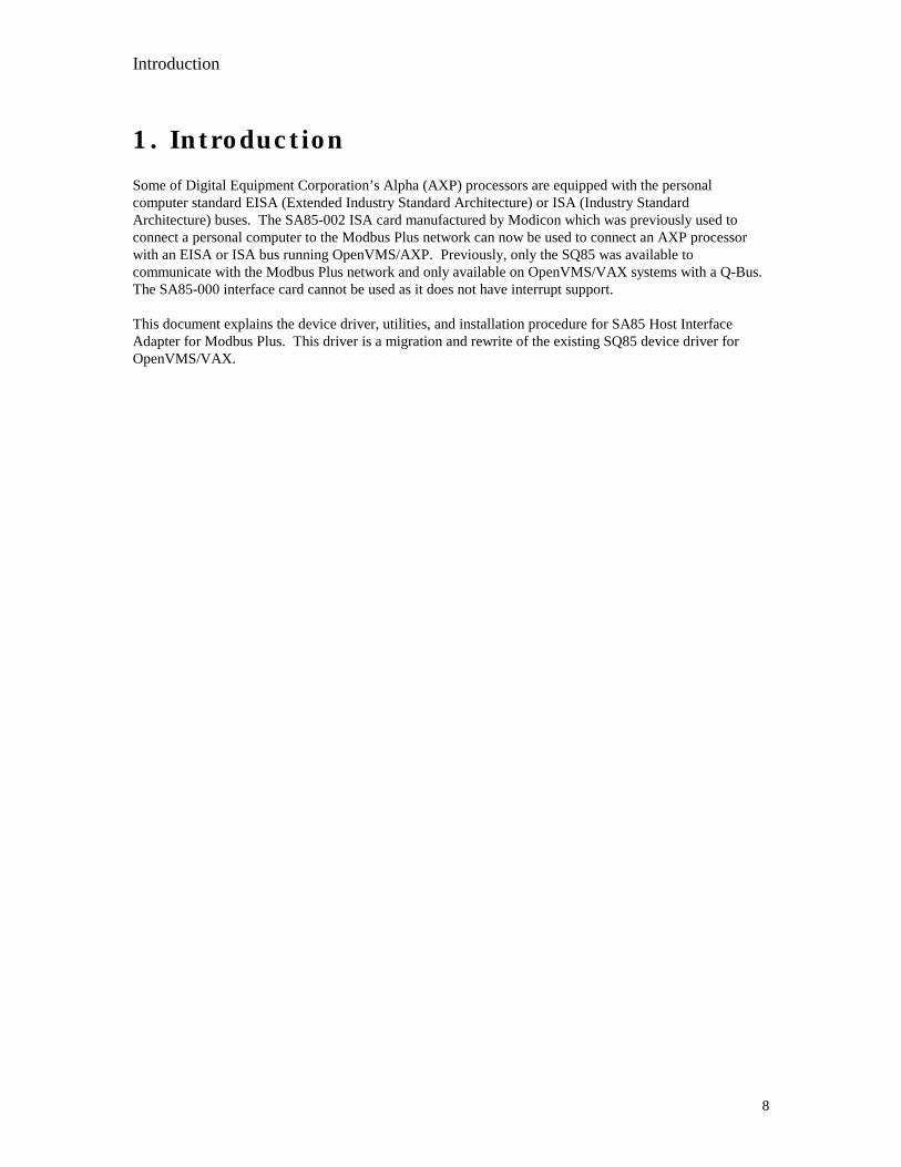
1. IntroductionSome of Digital Equipment Corporation’s Alpha (AXP) processors are equipped with the personalcomputer standard EISA (Extended Industry Standard Architecture) or ISA (Industry StandardArchitecture) buses. The SA85-002 ISA card manufactured by Modicon which was previously used toconnect a personal computer to the Modbus Plus network can now be used to connect an AXP processorwith an EISA or ISA bus running OpenVMS/AXP. Previously, only the SQ85 was available tocommunicate with the Modbus Plus network and only available on OpenVMS/VAX systems with a Q-Bus.The SA85-000 interface card cannot be used as it does not have interrupt support.
This document explains the device driver, utilities, and installation procedure for SA85 Host InterfaceAdapter for Modbus Plus. This driver is a migration and rewrite of the existing SQ85 device driver forOpenVMS/VAX.

SQ85 and SA85 Software Driver Comparison

SQ85 and SA85 Software Driver Comparison
10
2. SQ85 and SA85 Software DriverComparison
The QIO interface was maintained between both of these drivers. The user only needs to recompile andlink existing applications that made calls to the Modbus Plus device driver (MPDRIVER) forOpenVMS/VAX. The mechanism used to load the device driver (SYSMAN is used for OpenVMS/AXP),and some of the error log support has been changed. These particular items should not effect any userwritten applications. The user should reference the Modicon document: “DEC Host Based Devices User’sGuide” for a description of the QIO interface. The user should use the symbolic codes for the I/O functioncodes which are defined in the include file: “MP_FUNCS” contained in the MBP_C.TLB (C users) orMBP_FOR.TLB (FORTRAN users text libraries). This driver does not support Modbus Function codesthat are not documented in the appendix of this document.
The VMS error code message definition file has been renamed to MPDRIVER_MSG.OBJ and is includedin the MBP.OLB object library. This file may be included to translate the I/O status returned from thedriver via the sys$getmsg or sys$exit VMS system service calls. To include this module in the user’sapplication, add the following linker option:
mbplus_:mbp.olb/include=(mpdriver_msg)
The standard VMS method of testing for success or failure should be used (odd status is successful).Additional error codes were added to further enumerate possible driver errors. The include files:MPDRIVER_MSG in the text libraries: MBP_FOR.TLB and MBP_C.TLB define all of the error codes.

Utilities

Utilities
12
3. UtilitiesThe NDU utility has been migrated to the OpenVMS/AXP platform. Additionally, the MBP_ERRFMTutility has been provided that will format any error log packets generated by the MPDRIVER. DEVDMP,(diagnostic utility designed for the developers) is also provided which will extract information from thedriver database for bug reporting. The INSTALL_CK.COM command file is obsolete because the driversoftware is now installed with VMSINSTAL and loaded with SYSMAN.
3.1 Modbus Plus Message RoutingEach device establishes its host as a node on the Modbus Plus network. Up to 64 nodes can be present on asingle network, each with an unique address between 1 and 64. Multiple networks can be joined throughBridge Plus devices.
3.2 Modbus Plus Routing PathsNodes address each other using a routing path field of five bytes. The path is imbedded in the Modbus Plusmessage frame as sent from the originating node. The five bytes of routing allow destination nodes to beaddressed up to four networks away from the originating node. The routing bytes are used by each type ofdevice in a specific way, as illustrated below and on the next page.
Figure 1 - Message Frame Routing Path
MODBUS PLUSMESSAGE FRAME
ENDSTART
ROUTINGPATH
EXAMPLE: ROUTING ADDRESS 1 = 25ROUTING ADDRESS 2 = 20ROUTING ADDRESS 3 = 12ROUTING ADDRESS 4 = 0ROUTING ADDRESS 5 = 0
ROUTING ADDRESS 1ROUTING ADDRESS 2
ROUTING ADDRESS 3ROUTING ADDRESS 4
ROUTING ADDRESS 5

Utilities
13
The example in Figure 1 shows routing to a controller through three networks that are joined by a pair ofBridge Plus devices. Using the routing bytes in the example, the message will be sent first to node 25, aBridge Plus on the local network. That bridge forwards the message to a second Bridge Plus at nodeaddress 20 on the second network. The second bridge forwards the message to its final destination, acontroller at node address 12 on the third network. The zero contents of bytes 4 and 5 specify that nofurther routing will occur.
The routing path contents are specific to the type of device at the destination. Routing path methods forvarious networked devices are outlined below. For further details about message routing paths, see yourModbus Planning and Installation Guide (GM-MBPL-001).
3.2.1 Routing to Programmable Controllers
For 984 programmable controllers, including the AT-984 and MC-984, the last nonzero byte in the routingspecifies the network node address of the controller (range: 1...64). For example, the path 5.0.0.0.0specifies a controller node at address 5 on the local network (the network to which the host is attached).
3.2.2 Routing to Network Adapters
For host based network adapters such as the SA85 and SM85, the next to last nonzero byte specifies theadapter’s network node address (range: 1...64). The last nonzero byte specifies an internal path (range:1...8) to which the message is to be assigned. For example, if an adapter is at node address 35 on the localnetwork, the path 35.8.0.0.0 specifies routing to path 8 in that adapter. This last routing byte is the dataslave path for the OpenVMS SA85 Modbus Plus device driver. Modbus Plus Master nodes need to set thisbyte to the slave path that the OpenVMS user process is reading. This requires coordination between thePLC programmer and the OpenVMS programmer.
3.2.3 Routing to Bridge Multiplexers
For BM85 bridge multiplexers, the routing field contents are specific to the slave device configuration atthe multiplexer’s Modbus port. Either a single slave device or a network of slave devices can be connectedat the port.
A single slave device at a multiplexer’s Modbus port is addressed using two bytes. The next to last nonzerobyte addresses the multiplexer node (range: 1...64). The last nonzero byte specifies the port (range: 1...4) towhich the slave device is attached. Specifying the port automatically addresses the device at that port. Forexample, if a BM85 is at node address 25 on the local network, 25.1.0.0.0 routes a message to the singleslave device at the multiplexer’s port 1.
A networked slave device at the multiplexer’s port is addressed using three bytes. The third from lastnonzero byte addresses the multiplexer node (range: 1...64). The next to last nonzero byte specifies the port(range: 1...4) to which the network is attached. The last nonzero byte specifies the Modbus address of theslave device (range: 1...247). For example, 25.2.200.0.0 routes a message to multiplexer node address 25,port 2, slave device 200.

Utilities
14
3.3 Modbus Plus TransactionsWith multiple node devices processing messages asynchronously on the network, an individual devicemight have several concurrent transactions in process. Each device has multiple internal paths of varioustypes to allow concurrent processing of transactions. It opens a path when a transaction begins, keep itopen during processing of the transaction, and closes it when the transaction terminates. When the path isclosed, it becomes available to another transaction.
Both the originating and destination devices open paths for a mutual transaction, and maintain the pathsuntil the transaction completes. If the transaction passes through Bridge Plus devices to a destination onanother network, each bridge opens and maintains a path at each of its two network ports. Thus, a logicalpath is established between the originating and destination devices, and maintained until the transaction isfinished. When the transaction is completed, all of the paths it has used will be freed.
3.4 Path TypesEach Modbus Plus device contains the following types of paths:
Data Master (DM) Path This type of path is opened for data reads and writes, and forget and clear remotestatistics, as they are originated in the device.
Data Slave (DS) Path This type of path is opened for data reads and writes as they are received by thedevice.
Program Master (PM) Path This type of path is opened for programming commands as they areoriginated in the device.
Program Slave (PS) Path This type of path is opened for programming commands as they are received bythe device.
Each path is independent of the others. Activity in one path does not affect the performance of the otherpaths.

Utilities
15
3.4.1 Path Quantities
The following path quantities are available in the Modbus Plus devices:
Path Host Based 984s BM85 BP85 SA85/SM85/SQ85
Data Master 8* 4 8 8Data Slave 4 4 8 8Program Master 8* 4 8 8Program Slave 1 4 8 8
* Because the host based controllers have a virtual network adapter capability link built in, their pathquantities are different from other types of 984 controllers.
3.5 QueuingIf all DS paths are active in a device, new incoming transactions will be queued. Transactions will remainqueued until a path is available, and will then be removed from the queue and given the path. A final dataresponse will not be returned to the originating application until a full path is available from origin todestination.
When the destination node removes a transaction from its queue, it will wait for the network token and thenwill request the command again from the originating node. The originator will retransmit the commandwhile the destination retains the token. This process occurs transparently, eliminating the need for pollingbetween the origin and destination devices in the application.
BP85 Bridge Plus Queuing Messages which must pass through multiple bridges will be queued (ifnecessary) within the first bridge, but will not be queued within any subsequent bridges. An attempt toqueue in a second bridge will return an error code, which can be tested by the application program in theoriginating node. This prevents unpredictable delays from queuing across several networks. Theoriginating application can determine how to proceed with outstanding tasks, rather than having to waitthrough multiple levels of queuing. Tasks that are currently in progress can be allowed to continue, or canbe aborted in favor of a higher priority task.

Utilities
16
3.6 Modbus Data Access CommandsTransactions to or from programmable controller nodes are based on Modbus data access commands thatare imbedded into Modbus Plus frames. These commands are recognized by controllers for reading andwriting coils and registers, and for reporting status. The following Modbus commands are used:
Table 3 Modbus Data Access Commands
Function Code (Decimal) Command Name
1 Read Discrete Output Status (0xxxx)2 Read Discrete Input Status (1xxxx)3 Read Output Register (4xxxx)4 Read Input Register (3xxxx)5 Force Single Coil (0xxxx)6 Preset Single Register (4xxxx)7 Read Exception Status8* Get/Clear Network Statistics (Subfunction 21)15 Force Multiple Coils (0xxxx)16 Preset Multiple Registers (4xxxx)17 Report Slave ID
* Use only subfunction 21 of function 8 for Modbus Plus networking data.
Path Requirements: All of the Modbus data access commands require a Data Master path in the initiatingnode.

Installation

Installation
18
4. INSTALLATIONThe existing documentation in the Modicon “DEC Host Based Devices User’s Guide” is obsolete withregard to the installation of the OpenVMS software device driver. The IRQ strapping for the SA85 isshown on the SA85 itself. Place a jumper selecting the desired IRQ level. To install the software, theinstaller must know the following:
• Serial number of the first SA85 (SA85 with the lowest base address)• License number from IPACT Inc.• IRQ for each SA85• Base Address of each SA85 (Each SA85 must be 800 hex greater than each preceding SA85)• ALPHA Computer model• Release of OpenVMS
To install the software, mount the distribution media and execute VMSINSTAL. When prompted for thedistribution device, select the distribution device. When prompted for the product, type: “MBP019” or theproduct listed on the distribution kit. An example VMS install procedure is listed in the appendix. Theinstallation procedure provides a start up command file in the product directory :
SYS$COMMON:[MBPrrv]MBP_STARTUP.COM (Where: rr= release, v= version)
The system manager may execute this command file upon system startup to install the SA85 device driverand define system wide logical names. In particular, the command file will define the system wide logicalname: “MBPLUS_:” to point to the product directory. Foreign DCL command symbols may be defined byexecuting the MBP_SYMBOLS.COM command file in the product directory.
If your distribution is a combination distribution (includes Modbus Plus Interface Library), then you willalso be prompted for the optional installation of the Modbus Plus Process I/O Scanner and InterfaceLibrary.
Prior to actually installing the software, the user must configure the ISA cards using the ECU utility or theor the ISA configuration utility (ISACFG) provided with your Alpha system. If the ECU or ISACFGutilities are not run, the driver will load with only one unit available, and a device off line console messagewill be logged indicating that the device driver could not acquire any EISA/ISA configuration informationfor the SA85. If EISA/ISA configuration information is found for the SA85, two devices will be brought online, and a device on line console message will be printed. However, the device will not be made availableuntil the SA85 is successfully initialized. The system manager can use the DCL command “SHOWDEVICE” or the DEVDMP utility provided with this product to determine if the device was successfullybrought on line. Incorrect EISA configuration, SA85 hardware configuration, or incorrectinformation given during kit installation may result in system crashes or system instability. Thedevice driver logs a single errorlog log buffer when the device is attempted to be placed on line. TheSHOW DEVICE should show a count of one. If the number of errors increases, then suspect configurationproblems or inconsistent configuration information between the information entered during VMSINSTALand the configuration.
The user should execute the NDU utility to do simple tests to determine if the Alpha node is successfullyintegrated with the Modbus Plus network. Some of the NDU commands do not require a connection to aModbus Network. Without a network connection, testing of the SA85 and the device driver can still beaccomplished with the commands that request information from the SA85 itself.

Installation
19
4.1 SA85 Hardware Installation
The SA85 must be configured with an EISA/ISA IRQ and EISA/ISA Bus memory that do not conflict withother devices installed in the EISA/ISA bus. The SA85 must also be strapped to interrupt instead ofsimply being polled. If two SA85s are installed, only the first needs be assigned the address space with theEISA Configuration Utility (ECU). Sufficient address space should be acquired to contiguously map all ofthe SA85s that the user intends to install (2K bytes per SA85). Each subsequent SA85 should be assigned adifferent IRQ and the SA85 should be strapped with a base address 800 Hex larger than the previous SA85(e.g. C0000, C0800, C1000, etc. ). The SA85 itself has the IRQ jumpers silk screened on the card adjacentto the jumpers. By default, the card is strapped in polled mode from the factory. Move the jumper from thepolled mode position to the desired IRQ position.
Assuming that the SA85 was strapped as follows:
Base MemoryAddress
C0000
IRQ 4Polled Mode Jumper RemovedSlot 4ALPHA Model AXP150
4.2 Software Driver Load
The following command to the SYSMAN utility could be used to load the device driver. This command toload the driver is contained in the MBP_STARTUP.COM command file that is built for the user by theVMSINSTAL kit procedure. It is shown here for custom installations and for understanding. The currentrelease of OpenVMS does not support the unloading of a device driver. Errors in configuration require areboot of the system to reload the driver.
$mcr sysman -io connect jpa0/driver=sys$mpdriver-/vector=16-/ADAPTER=2-/node=%x00040004-/csr=%xFFFFFFFF85960000-/NUM_UNITS=2-/MAX_UNITS=34-/LOG=ALL
The CSR is the CSR of the EISA adapter and may be different on other AXP processors. The maximumnumber of units is selectable, but selects the maximum number of UCBs that will be cloned for theparticular SA85 device. The value of 34 allows all paths plus two additional UCBs for the internal use bythe driver (UCB is an internal data structure, each device in OpenVMS has a UCB that describes thedevice). The “/node” specifies both the IRQ and the Slot of the SA85. The Vector is the IRQ times four.

Installation
20
The adapter number (EISA TR# from below) and the CSR of the EISA adapter (Base CSR) can beacquired by using SYSMAN as follows:
$MCR SYSMAN IO SHOW BUS_Bus__________Node_TR#__Name____________Base CSR__________EISA 2 2 Lance NI Adapt FFFFFFFF85A60000AHA_1742A 6 4 SCSI Adapter FFFFFFFF85C60000AHA_1742A 6 4 Floppy FFFFFFFF85960000
VTI_COMBO 0 3 Parallel Port FFFFFFFF863CC000
4.3 Using EISA Configuration Utility (ECU)
Since the SA85 is an ISA card and not an EISA card, the product id and other configuration registers arenot present. This prevents the ECU utility from being able to auto configure the SA85. A configuration fileis provided to you that will allow you to configure a single SA85-02 host adapter into your EISA bus. Afterinvoking ECU and during the “add” phase, select the file “!MOD8502.cfg” from the ECU floppy suppliedwith your distribution kit. This file may be copied to your normal ECU system floppy using a normalPersonal Computer (the ECU floppy is a DOS readable floppy).
4.4 Using ISACFGYou must manually allocate the memory and the IRQ for the SA85 after you install it in the ISA bus usingthe ISACFG (see your computer manuals for instructions on using the ISACFG software shipped with yousystem). All of the SA85 is mapped using bus memory and not I/O space.

Installation
21
4.5 Setting the Modbus Plus Address
Set Modbus Plus node address switches 1-6 to the address in your application. Switches 7 and 8 are notused. Each node must have an unique address. Note that the address will be one higher than the binaryvalue you set into the switches.
It is recommended that you reserve address 64 for future network maintenance. It is also recommended thatyou do not use address 1, to avoid possible confusion when using a local default address of 1 at a controllernode’s programming panel.
Memory WindowBase AddressSwitches
Modbus PlusNetwork AddressSwitches

Installation
22
MODBUS PLUS SWITCH POSITION MODBUS PLUS SWITCH POSITION ADDRESS 1 2 3 4 5 6 ADDRESS 1 2 3 4 5 6
1 0 0 0 0 0 0 33 0 0 0 0 0 12 1 0 0 0 0 0 34 1 0 0 0 0 13 0 1 0 0 0 0 35 0 1 0 0 0 14 1 1 0 0 0 0 36 1 1 0 0 0 15 0 0 1 0 0 0 37 0 0 1 0 0 16 1 0 1 0 0 0 38 1 0 1 0 0 17 0 1 1 0 0 0 39 0 1 1 0 0 18 1 1 1 0 0 0 40 1 1 1 0 0 19 0 0 0 1 0 0 41 0 0 0 1 0 110 1 0 0 1 0 0 42 1 0 0 1 0 111 0 1 0 1 0 0 43 0 1 0 1 0 112 1 1 0 1 0 0 44 1 1 0 1 0 113 0 0 1 1 0 0 45 0 0 1 1 0 114 1 0 1 1 0 0 46 1 0 1 1 0 115 0 1 1 1 0 0 47 0 1 1 1 0 116 1 1 1 1 0 0 48 1 1 1 1 0 117 0 0 0 0 1 0 49 0 0 0 0 1 118 1 0 0 0 1 0 50 1 0 0 0 1 119 0 1 0 0 1 0 51 0 1 0 0 1 120 1 1 0 0 1 0 52 1 1 0 0 1 121 0 0 1 0 1 0 53 0 0 1 0 1 122 1 0 1 0 1 0 54 1 0 1 0 1 123 0 1 1 0 1 0 55 0 1 1 0 1 124 1 1 1 0 1 0 56 1 1 1 0 1 125 0 0 0 1 1 0 57 0 0 0 1 1 126 1 0 0 1 1 0 58 1 0 0 1 1 127 0 1 0 1 1 0 59 0 1 0 1 1 128 1 1 0 1 1 0 60 1 1 0 1 1 129 0 0 1 1 1 0 61 0 0 1 1 1 130 1 0 1 1 1 0 62 1 0 1 1 1 131 0 1 1 1 1 0 63 0 1 1 1 1 132 1 1 1 1 1 0 64 1 1 1 1 1 1

Installation
23
4.6 Setting the Memory
The SA85 board uses a memory area in your computer as a buffer for the board’s status and messagetransactions. You must define a base address for this memory area that prevents conflict with other optionboards in your computer.
Valid base address settings range from C0000...EF800 hexadecimal. The area used in memory is a 2Kbytes (800 hex) portion starting at the base address. Refer to your computer’s manual to determineavailable areas of free memory. Select an area that will not be overwritten by your application or by otheroptions and record the address. You will need it later when you setup your CONFIG.SYS file.
The top part of Figure 2 shows the address bus range from all 0 to all 1, with the portion seen by the board’sswitches. The bottom part of the figure shows the lowest and highest base addresses in binary andhexadecimal.
SWITCH POSITION1 2 3 4 5 6 7
1 1 0 0 0 0 0 0 0 0 0 0 0 0 0 0 0 0 0 0. . . . . . . . . . . . . . . . . . . .. . . . . . . . . . . . . . . . . . . .1 1 1 1 1 1 1 1 1 1 1 1 1 1 1 1 1 1 1 1Always Compared with SA85 2K Range of Memory Window
one Switches
BASE ADDRESS RANGE
C 0 0 0 01 1 0 0 0 0 0 0 0 0 0 0 0 0 0 0 0 0 0 0. . . . . . . . . . . . . . . . . . . .. . . . . . . . . . . . . . . . . . . .1 1 1 1 1 1 1 1 1 1 1 1 1 1 1 1 1 1 1 1
E F 8 0 0
Figure 2 - SA85 Memory Window Addressing Method
A19 A18 A17 A16 A15 A14 A13 A12 A11 A10 A9 A8 A7 A6 A5 A4 A3 A2 A1 A0
Installation
24
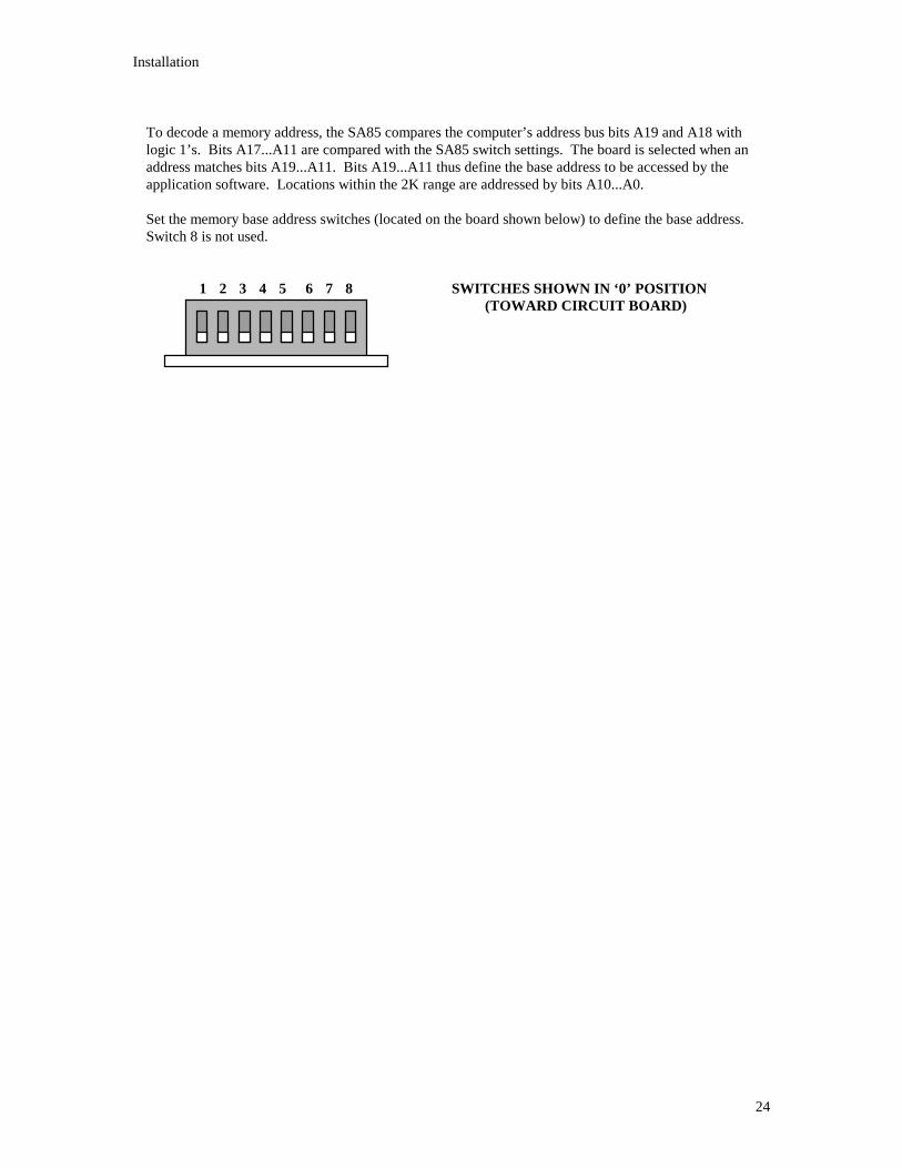
To decode a memory address, the SA85 compares the computer’s address bus bits A19 and A18 withlogic 1’s. Bits A17...A11 are compared with the SA85 switch settings. The board is selected when anaddress matches bits A19...A11. Bits A19...A11 thus define the base address to be accessed by theapplication software. Locations within the 2K range are addressed by bits A10...A0.
Set the memory base address switches (located on the board shown below) to define the base address.Switch 8 is not used.
1 2 3 4 5 6 7 8 SWITCHES SHOWN IN ‘0’ POSITION(TOWARD CIRCUIT BOARD)

Installation
25
BASE SWITCH POSITION BASE SWITCH POSITIONADDRESS 1 2 3 4 5 6 7 ADDRESS 1 2 3 4 5 6 7
C0000 0 0 0 0 0 0 0 D2800 0 1 0 0 1 0 1C0800 0 0 0 0 0 0 1 D3000 0 1 0 0 1 1 0C1000 0 0 0 0 0 1 0 D3800 0 1 0 0 1 1 1C1800 0 0 0 0 0 1 1 D4000 0 1 0 1 0 0 0C2000 0 0 0 0 1 0 0 D4800 0 1 0 1 0 0 1C2800 0 0 0 0 1 0 1 D5000 0 1 0 1 0 1 0C3000 0 0 0 0 1 1 0 D5800 0 1 0 1 0 1 1C3800 0 0 0 0 1 1 1 D6000 0 1 0 1 1 0 0C4000 0 0 0 1 0 0 0 D6800 0 1 0 1 1 0 1C4800 0 0 0 1 0 0 1 D7000 0 1 0 1 1 1 0C5000 0 0 0 1 0 1 1 D7800 0 1 0 1 1 1 1C5800 0 0 0 1 0 1 1 D8000 0 1 1 0 0 0 0C6000 0 0 0 1 1 0 0 D8800 0 1 1 0 0 0 1C6800 0 0 0 1 1 0 1 D9000 0 1 1 0 0 1 0C7000 0 0 0 1 1 1 0 D9800 0 1 1 0 0 1 1C7800 0 0 0 1 1 1 1 DA000 0 1 1 0 1 0 0C8000 0 0 1 0 0 0 0 DA800 0 1 1 0 1 0 1C8800 0 0 1 0 0 0 1 DB000 0 1 1 0 1 1 0C9000 0 0 1 0 0 1 0 DB880 0 1 1 0 1 1 1C9800 0 0 1 0 0 1 1 DC000 0 1 1 1 0 0 0CA000 0 0 1 0 1 0 0 DC800 0 1 1 1 0 0 1CA800 0 0 1 0 1 0 1 DD000 0 1 1 1 0 1 0CB000 0 0 1 0 1 1 0 DD800 0 1 1 1 0 1 1CB800 0 0 1 0 1 1 1 DE000 0 1 1 1 1 0 0CC000 0 0 1 1 0 0 0 DE800 0 1 1 1 1 0 1CC800 0 0 1 1 0 0 1 DF000 0 1 1 1 1 1 0CD000 0 0 1 1 0 1 0 DF800 0 1 1 1 1 1 1CD800 0 0 1 1 0 1 1 E0000 1 0 0 0 0 0 0CE000 0 0 1 1 1 0 0 E0800 1 0 0 0 0 0 1CE800 0 0 1 1 1 0 1 E1000 1 0 0 0 0 1 0CF000 0 0 1 1 1 1 0 E1800 1 0 0 0 0 1 1CF800 0 0 1 1 1 1 1 . . . . . . . . . .D0000 0 1 0 0 0 0 0 . . . . . . . . . .D0800 0 1 0 0 0 0 1 EE000 1 0 1 1 1 0 0D1000 0 1 0 0 0 1 0 EE800 1 0 1 1 1 0 1D1800 0 1 0 0 0 1 1 EF000 1 0 1 1 1 1 0D2000 0 1 0 0 1 0 0 EF800 1 0 1 1 1 1 1
Installation
26
4.7 Verifying the Jumpers
4.7.1 Polled Mode Jumper
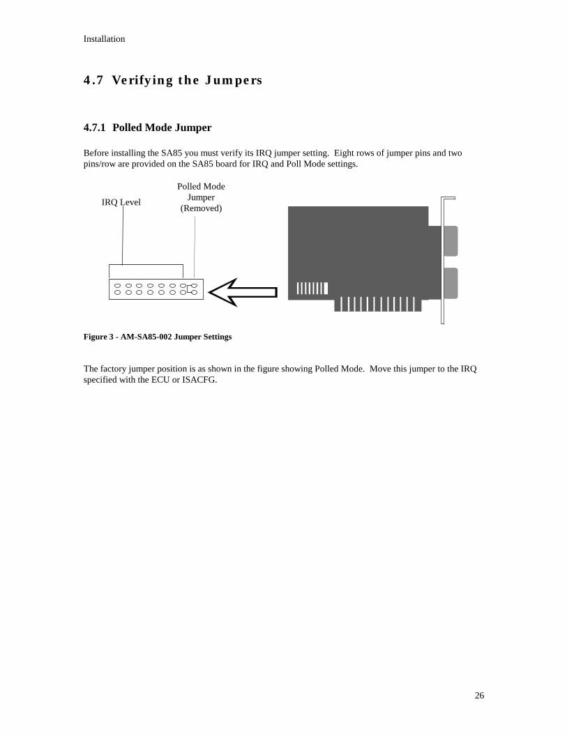
Before installing the SA85 you must verify its IRQ jumper setting. Eight rows of jumper pins and twopins/row are provided on the SA85 board for IRQ and Poll Mode settings.
Figure 3 - AM-SA85-002 Jumper Settings
The factory jumper position is as shown in the figure showing Polled Mode. Move this jumper to the IRQspecified with the ECU or ISACFG.
IRQ Level
Polled ModeJumper
(Removed)

Installation
27
4.8 Installing the SA85 Board
Use these guidelines to install the SA85 board and connect it to the network cable:
Step 1 Run ECU or ISACFG to determine a valid IRQ, memory base address, and ISA or EISAslot for the SA85
Step 2 If you have not set and verified the SA85 network address, memory base address, andjumper, do so now. Refer to the procedures earlier in this chapter to set them.
Step 3 Referring to your computer’s product documentation, set the computer power switch toOFF and unplug its power cable from the power source.
Step 4 Remove the computer cover. Retain the bolts and other hardware for later reassembly.
Step 5 Locate the selected expansion slot connector on the computer motherboard that matchesyour selection in step one. Remove the bolt securing the blank rear faceplate for thisslot position and remove the faceplate. Retain the bolt for later reassembly.
Step 6 Insert the SA85 board into the expansion slot connector. Make sure the board is firmlyseated in the connector.
Step 7 Install the bolt to secure the board’s rear faceplate to the computer frame.
NOTE: This bolt is required for proper grounding of the board.
Step 8 Reinstall the computer cover.
Step 9 Plug the Modbus Plus network cable connector(s) into the board’s connector(s). If youhave a dual-cable network, your two cables should be labeled A and B. Make sure toconnect the cables into the proper connectors (A and B). Secure each connector bytightening its two screws.
Step 10 Reconnect the computer power cable and power up the computer. Verify normaloperation with the board installed.
Step 11 Execute the VMSINSTAL from the system account from sys$update.
Note: If new ALPHA firmware upgrade is done, the ECU configuration is erased. The ECU utility must bereloaded after a firmware upgrade.

Installation
28
Reading the Network Indicator
AM-SA85-002: This board has three indicators. A green indicator shows the overall communicationstatus at the SA85 node. Two red indicators identify faults on the two cable paths.
If a red indicator blinks momentarily, it indicates that a message error was detected on the cable path. Asteady ON state indicates a hard fault either in the cable or in a node device connected to the cable. Ifcommunication is lost on one cable path, the other path continues normally.
Figre 4 - SA85 Network Indicators
Network Communication Status (Green Indicator)Modbus Plus status is shown by flashing a repetitive pattern on the green indicator. The patterns are:
Six flashes per secondThe node’s normal operating state. The node is successfully receiving and passing the token. All nodes onthe network should be flashing this pattern.
One flash per secondThe node is offline after just being powered up, or after exiting the four flashes per second mode. In thisstate, the node monitors the network and builds a table of active nodes and token-holding nodes. It remainsin this state for five seconds, then attempts to go to its normal operating state.
Two flashes, then OFF for two secondThe node is hearing the token being passed among other nodes, but is never receiving the token. Check thenetwork for an open circuit or defective termination.
Three flashes, then OFF for 1.7 secondsThe node is not hearing any other nodes. It is periodically claiming the token, but finding no other node towhich to pass it. Check the network for an open circuit or defective termination.
Four flashes, then OFF for 1.4 secondsThe node has heard a valid message from another node that is using the same address as this node. Thenode remains in this state as long as it continues to hear the duplicate address. If the duplicate address isnot heard for five seconds the node then changes to the pattern of one flash every second.
AM-SA85-002
B
A
NETWORKINDICATOR(GREEN)
CABLE BPATHFAULT(RED)
CABLE APATHFAULT(RED)

Installation
29
4.9 Labeling the Modbus Plus Port
Two sets of labels are provided with the SA85 to identify its Modbus Plus network and node address. Onelabel should be attached to the unit when you complete the connection to the network. The other set is aspare.
Enter onto the label the Modbus Plus network number and node address you have assigned to the SA85.Place the label on the unit so that it can easily be seen. Figure 5 shows an example of the completed label.The user should also document the IRQ and Base address of the SA85 for future use.
Figure 5 - SA85 Modbus Plus Port Label
Modbus Plus
2
34
Network
Node

Device Driver Functionality
Device Driver Functionality
31
5. Using the Device Driver� Device Driver Overview � Device Names in VMS Requests � Modbus Plus Paths in VMS Processes � Summary of $QIO/$QIOW Requests � Handling Errors � Error Logging
5.1 Device Driver Overview
The OpenVMS device driver, MPDRIVER, is a kernel loadable software module that handles calls fromVMS processes for transacting messages with a selected host-based Modbus Plus network device controller.The driver functions as an integral part of the OpenVMS executive. The driver provides user processesaccess to data and statistics on Modbus Plus network nodes through a standard set of VMS system services.
Devices in the local host processor or at remote sites across the Modbus Plus network are accessed in thesame manner. Messages use the Modbus Plus five-byte routing path and node addresses to specify thesource and destination nodes. For messages originated in the process, the user supplies the routinginformation as a portion of the message header that is stored in an outgoing buffer. For device responses,the routing is returned along with the response message contents to the incoming buffer.
The driver performs buffered I/O operations in which data passes through an intermediate buffer in systemaddress space. Direct Memory Access operations are not supported by the Modbus Plus network devices.
VMS processes access device drivers through the following OpenVMS system services:
� $ALLOC and $DALLOC - to reserve a device for exclusive use � $ASSIGN and $DASSGN - to establish a channel to a device � $QIO and $QIOW - to communicate with a device across an assigned channel.
The general use and application of these services are described in detail in the VMS Programming Manual,Volume 4B - System Services. Their use with the host-based devices is outlined below.

Device Driver Functionality
32
5.1.1 $ALLOC and $DALLOC
VMS provides the $ALLOC service to grant an user process exclusive access to a device, and the$DALLOC to remove the exclusive access. However, because the Modbus Plus devices are of a specialtype (they use ‘cloned’ Unit Control Blocks), they cannot be allocated for exclusive use.
An error will be returned from a $ALLOC request if your application attempts to issue it for one of thesedevices.
5.1.2 $ASSIGN and $DASSGN
A process that wishes to issue $QIO or $QIOW service requests to a device must assign a channel to thedevice before the $QIO or $QIOW call can be issued. The process does this through the $ASSIGN servicerequest with a parameter that specifies the target device. VMS returns a condition value indicating thesuccess or failure of the request.
If the request is successful, VMS returns a channel number. The requesting process can then make $QIOand $QIOW service requests to the device by specifying the assigned channel number in those requests.
When a process has completed its operations across a channel, it should invoke the $DASSGN systemservice to deassign the channel. If a process exits, VMS issues $DASSGN requests for any channels thatare still assigned. The user only assigns a channel to unit number one for each controller (e.g. JPA1:). Theactual unit created may be any unit number as the device is cloned similar to OpenVMS mailboxes.
Each Modbus Plus device maintains multiple internal paths for handling concurrent transactions. A processcan assign multiple channels to access the multiple paths in a device, but this is generally not necessary.Typically a single channel would be assigned to the device for each type of access (data master, data slave,program master, or program slave) with all of the $QIO/$QIOW requests issued over that channel. ModbusPlus device paths are described in Chapter 1. Their use in processes that employ various types ofnetworked devices and network topologies is described in the Modbus Plus Network Planning andInstallation Guide.
5.1.3 $QIO and $QIOW
After a channel has been assigned to a particular device, a process can issue $QIO and $QIOW systemservice calls across the channel. These calls request VMS to place the specified type of I/O request into theinput queue of the driver for the targeted device.
$QIO is an asynchronous request that is queued to the device driver and handled by it while the processcontinues. $QIOW is a synchronous request that queues to the driver and blocks the process while waitingfor the response from the device.
$QIO/$QIOW calls are available for controlling device paths, issuing data and program commands, issuingresponses, sending and receiving global data, and getting device configuration and statistics information.Descriptions of the syntax, parameters, and returned values for the calls are contained in Chapter 5.

Device Driver Functionality
33
VMS returns a condition value indicating the success or failure of the attempt to queue the I/O request. Theoutcome of the requested I/O action is stored in a quadword status block that is specified in the$QIO/$QIOW request. The block is accessible to the process for monitoring the device. The Modicondevice status block format differs from the typical block format. A description of the block is provided inthe next chapter. The status codes returned by the driver are documented in the appendix. If the user linkswith the MPDRIVER OpenVMS message file, the status code may be translated with the OpenVMSSYS$GETMSG and SYS$EXIT system services.
5.2 Device Names in VMS Requests
Up to four Modbus Plus devices can be installed on a OpenVMS/AXP host with an ISA or EISA bus. Thenumber of SA85s it typically limited by the IRQs and available slots on the EISA or ISA bus. Each of theSA85 devices are referred to as devices A, B, C, and D. Device names used in VMS requests to the deviceshave four parts:
� The prefix: JP � The device identifies: A, B, C, or D � The unit number: 1 � A trailing colon.
For example, if one device is installed it will be referred to as device JPA1:. The allowable range of devicenames is JPA1:, JPB1:, JPC1:, and JPD1:.
Note: There are two unit numbers created for each installed SA85 device during the loading of the devicedriver. For example, if one device was installed it was configured as both JPA0 and JPA1 (see theCONNECT statement examples in each device’s installation chapter). The unit 0 reference is reserved forthe driver program’s internal use. It must be not used in your application program. VMS service requeststo the unit 0 reference will return an error MP$_WRONGUCB. The unit 1 (JPA1:) reference is for youruse in the service requests for user applications.

Device Driver Functionality
34
5.2.1 Using $ASSIGN
The format of the $ASSIGN request is:
SYS$ASSIGN devnam, chan, [acmode], [mbxnam]
where:
devnam is the address of a character string descriptor pointing to the device name string.The string contents are the device name, e.g., “JPA1:’.
chan is the address of a work into which $ASSIGN will write the VMS I/O channelnumber if the request is successful.
acmode and mbxnam are optional arguments defining the access mode and mailbox name to beassociated with the device. Refer to the VMS Programming Manual, Volume 4B - System Servicesfor descriptions of these arguments.
The following C code fragment illustrates a call to the $ASSIGN request:
unsigned short channel ;unsigned long status ;$DESCRIPTOR (device, “JPA1:”) ;
status = SYS$ASSIGN (&device &channel,,) ;
5.2.2 Using $DASSGN
The format for the $DASSGN request is:
$SYS$DASSGN chan
where:
chan is a word containing the number of the I/O channel to be deassigned.
The following C code fragment illustrates a call to the $DASSGN request:
unsigned short channel ;unsigned long status ;
status = SYS$DASSGN(channel) ;
Typical condition values returned by VMS to the $DASSGN request include:
SS$_NORMAL the service was completed successfullySS$_IVCHAN an invalid channel number was specifiedSS$_NOPRIV the specified channel is not assigned or was assigned from a more
privileged access mode

Device Driver Functionality
35
5.3 Modbus Plus Paths in VMS ProcessesModbus Plus device paths are separate entities from VMS I/O channels. The VMS requests $ASSIGN and$DASSGN handle the assignment of VMS I/O channels. After an I/O channel has been assigned, internalModbus Plus paths in the host’s local device are allocated by $QIO/$QIOW requests. Paths in remotenetworked devices are not allocated by the local process, but are handled by their respective processes asrequired by the types and quantities of transactions at those nodes.
A VMS process wanting to issue a series of commands and responses with a remote Modbus Plus devicemust allocate a path within the host’s local device. Of the available $QIO/$QIOW commands, only fourrequire prior allocation of a path. Those are listed on the opposite page.
When the path has been allocated, the process can then issue commands and responses through the localdevice to the remote device. It can issue the required sequence of $QIO/$QIOW requests to complete thetype of transaction intended.
A typical sequence of operations in two processes handling communication between a Master and Slavedevice would be:
In the Master Process: $ASSIGN Assign I/O Channel$QIO Allocate Master Path$QIO Write Master Command
. . .$QIO Write Master Command$QIO Read Master Response$QIO Deallocate Master Path$DASSGN Deassign I/O Channel
In the Slave Process: $ASSIGN Assign I/O Channel$QIO Allocate Slave Path$QIO Read Slave Path$QIO Write Slave Response
. . .$QIO Read Slave Command$QIO Write Slave Response$QIO Deallocate Slave Path$DASSGN Deassign I/O Channel
You will notice that these Modbus Plus transactions occur in pairs. Typically the matching transaction mustbe responded to in a timely manner (typically two seconds). The driver ensures that the matchingtransaction is processed next by rejecting any other requests. Failure to respond promptly may result incontroller crashes, path aborts, or path down status.
Device Driver Functionality
36
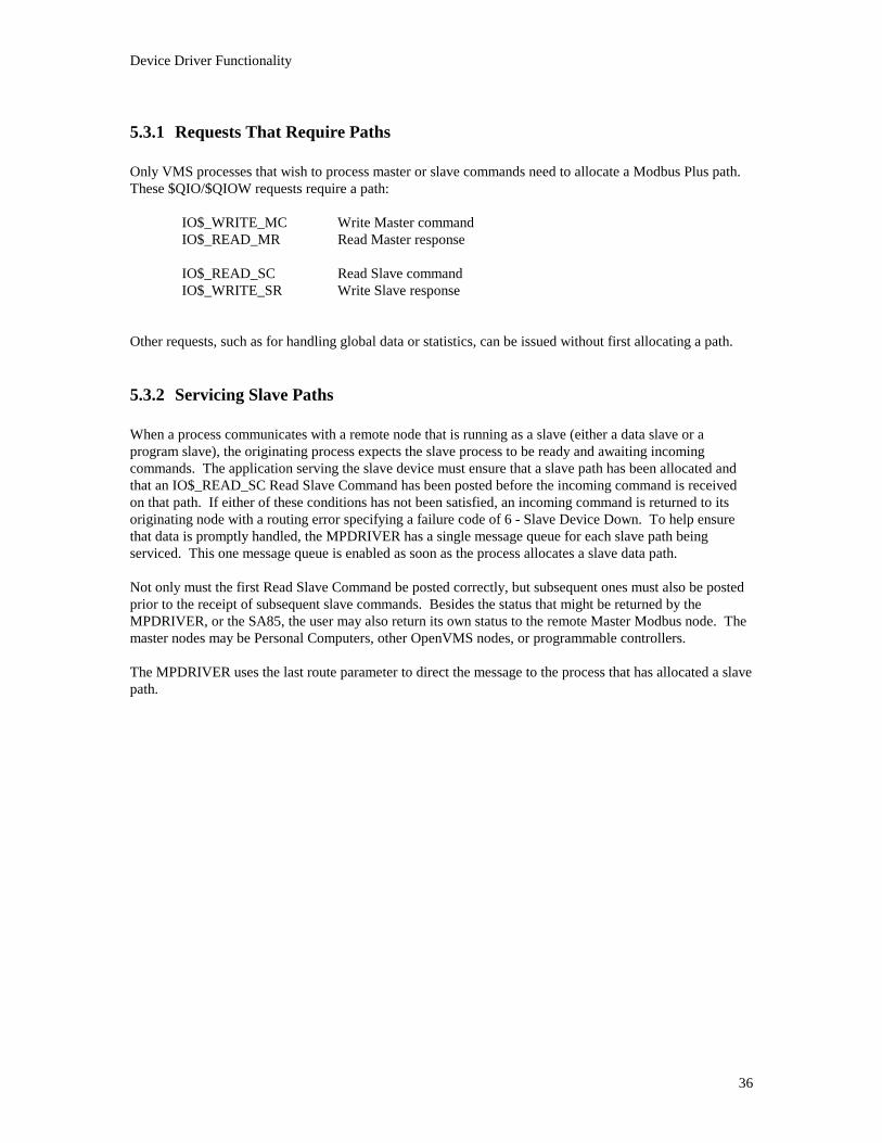
5.3.1 Requests That Require Paths
Only VMS processes that wish to process master or slave commands need to allocate a Modbus Plus path.These $QIO/$QIOW requests require a path:
IO$_WRITE_MC Write Master commandIO$_READ_MR Read Master response
IO$_READ_SC Read Slave commandIO$_WRITE_SR Write Slave response
Other requests, such as for handling global data or statistics, can be issued without first allocating a path.
5.3.2 Servicing Slave Paths
When a process communicates with a remote node that is running as a slave (either a data slave or aprogram slave), the originating process expects the slave process to be ready and awaiting incomingcommands. The application serving the slave device must ensure that a slave path has been allocated andthat an IO$_READ_SC Read Slave Command has been posted before the incoming command is receivedon that path. If either of these conditions has not been satisfied, an incoming command is returned to itsoriginating node with a routing error specifying a failure code of 6 - Slave Device Down. To help ensurethat data is promptly handled, the MPDRIVER has a single message queue for each slave path beingserviced. This one message queue is enabled as soon as the process allocates a slave data path.
Not only must the first Read Slave Command be posted correctly, but subsequent ones must also be postedprior to the receipt of subsequent slave commands. Besides the status that might be returned by theMPDRIVER, or the SA85, the user may also return its own status to the remote Master Modbus node. Themaster nodes may be Personal Computers, other OpenVMS nodes, or programmable controllers.
The MPDRIVER uses the last route parameter to direct the message to the process that has allocated a slavepath.

Device Driver Functionality
37
5.3.3 Path States and Transitions
Paths are assigned a state by the driver. The three possible states are:
Available: ready to be allocatedAllocated: allocated but not processing a commandBusy: allocated and currently processing a command
Paths transition from one state to another as a result of $QIO/$QIOW requests. A summary of theserequests and the path transitions caused by them is provided later in this chapter. The driver returns anerror value for unsuccessful attempts to use paths:
� An attempt to allocate a path that is not Available results in a path unavailable error(MP$_PATHUNAVL).
� An attempt to issue a Write Master Command on a path that is Busy results in a path state error
(MP$_PATHSTAT). � An attempt to issue a Read Master Response on a path that is not Busy results in a path state error
(MP$_PATHSTAT). � An attempt to issue a Read Slave Command on a path that is not Busy results in a path state error
(MP$_PATHSTAT). � An attempt to issue a Write Slave Response on a path that is not Busy results in a path state error
(MP$_PATHSTAT).
5.3.4 Deallocating Paths
A process should deallocate a path when it is no longer needed. This is done by issuing an explicitIO$_DEALLOC $QIO/$QIOW request. Note also that deassigning a channel through $DASSGN willcause a path allocated to the channel to be deallocated. If a process exits the system, VMS issues a$DASSGN call for any assigned channels with the same effect. Deallocated paths transition to Available.
5.3.5 Aborting a Path
The IO$_ABORT Abort Transaction $QIO/$QIOW request transitions a path state from Busy to Allocatedwithout completing the transaction in progress. It also causes the peer processor in the device to completeits cleanup of the transaction.
Note that the Abort Transaction request is queued in an I/O channel’s queue and is not processed until allother requests issued before it on the channel are complete. It does not affect any $QIO/$QIOW requestspreviously queued.
Device Driver Functionality
38
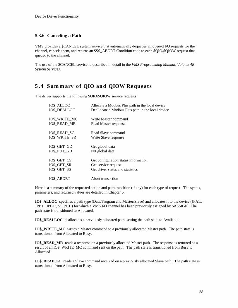
5.3.6 Canceling a Path
VMS provides a $CANCEL system service that automatically dequeues all queued I/O requests for thechannel, cancels them, and returns an $SS_ABORT Condition code to each $QIO/$QIOW request thatqueued to the channel.
The use of the $CANCEL service id described in detail in the VMS Programming Manual, Volume 4B -System Services.
5.4 Summary of QIO and QIOW RequestsThe driver supports the following $QIO/$QIOW service requests:
IO$_ALLOC Allocate a Modbus Plus path in the local deviceIO$_DEALLOC Deallocate a Modbus Plus path in the local device
IO$_WRITE_MC Write Master commandIO$_READ_MR Read Master response
IO$_READ_SC Read Slave commandIO$_WRITE_SR Write Slave response
IO$_GET_GD Get global dataIO$_PUT_GD Put global data
IO$_GET_CS Get configuration status informationIO$_GET_SR Get service requestIO$_GET_SS Get driver status and statistics
IO$_ABORT Abort transaction
Here is a summary of the requested action and path transition (if any) for each type of request. The syntax,parameters, and returned values are detailed in Chapter 5.
IO$_ALLOC specifies a path type (Data/Program and Master/Slave) and allocates it to the device (JPA1:,JPB1:, JPC1:, or JPD1:) for which a VMS I/O channel has been previously assigned by $ASSIGN. Thepath state is transitioned to Allocated.
IO$_DEALLOC deallocates a previously allocated path, setting the path state to Available.
IO$_WRITE_MC writes a Master command to a previously allocated Master path. The path state istransitioned from Allocated to Busy.
IO$_READ_MR reads a response on a previously allocated Master path. The response is returned as aresult of an IO$_WRITE_MC command sent on the path. The path state is transitioned from Busy toAllocated.
IO$_READ_SC reads a Slave command received on a previously allocated Slave path. The path state istransitioned from Allocated to Busy.

Device Driver Functionality
39
IO$_WRITE_SR writes a response to a previously allocated Slave path. The response is sent as a resultof an IO$_READ_SC command received on the path. The path state is transitioned from Busy toAllocated.
IO$_GET_GD retrieves global data for a specified node and places it into an user buffer.
IO$_PUT_GD replaces the local device’s global data with the new data specified in an user buffer.
IO$_GET_CS retrieves the current configuration status from a specified node and places it into an userbuffer. An optional function modifier causes the node’s error counters to be cleared after they are read.
IO$_GET_SR retrieves the current service request information from a specified node and places it into anuser buffer.
IO$_GET_SS retrieves the current driver status and statistics for a specified device and places it into auser buffer. Information includes: the driver version, device type, and node address; the latest VMScommand to the driver, the driver response, and any crash code; the current state of the Program Masterpath for the device; and statistics pertaining to the controlling of paths, interrupts, timeouts, and other driverparameters.
IO$_ABORT transitions the path state from Busy to Allocated. A typical use for a Master path would beto abort a transaction in progress after previously sending a Write Master Command (instead of issuing aRead Master Response). A typical use for a Slave path would be to abort a transaction upon receipt of aRead Slave Command (instead of issuing a Write Slave Response).
Device Driver Functionality
40
5.5 Handling ErrorsIf a device error occurs as a result of a specified $QIO/$QIOW request, the process can recognize the errorby examining the condition code returned in the I/O status block specified in the $QIO/$QIOW request.The device error conditions are:
� Controller timeouts - when a device does not respond to a command � Controller errors - when a device responds to a command with invalid data � Controller crashes - when a device experiences a logic or hardware fault
5.5.1 Device Errors
All commands issued by the driver require a response from the device. These responses are generatedinternally by the device and do not require that any network traffic occur.
The drive maintains a timeout timer on each command to ensure that it completes. A failure to complete acommand in time causes the driver to complete the current $QIO/$QIOW request (if any) and to return aController Timeout condition code (MP$_CTRLTMO) to the request. If a data error has occurred as aresult of the $QIO/$QIOW request, a Controller Error code (MP$_CTRLERR) will be returned. If a logicor hardware error occurs, the driver returns a controller Crash (MP$_CTRLCRASH) code.
5.5.2 Process Recovery From a Device Error
In addition to the returned code, the driver takes these steps to reset the device:
� The device is marked offline during the reset operation.
� The error is logged, using the standard VMS error logging facility.
� Any $QIO/$QIOW requests already queued to the device, and any new requests to it during the resetoperation, are completed with a device error indicating that the controller is being reset or that aparticular path is being aborted.
� All of the device paths that were in the Busy state are transitioned to Allocated. No allocated Paths aredeallocated.
� The device is initialized, and if this is successful, it is returned to online.

Device Driver Functionality
41
If an MP$_CTRLTMO, MP$_CTRLERR, or MP$_CTRLTMO condition code is received in response to a$QIO/$QIOW request, these steps should be taken by the application:
� The affected program should reset its own context: no logins or transactions are active following theerror.
� Any channels and paths in use before the error are still available to the process: the channels are still
assigned, and the paths are in the Allocated state. Any $QIO/$QIO requests that were active on thosechannels have been aborted.
� The VMS system administrator should be requested to print the VMS error log when it is convenient to
do so.
5.5.3 Process Recovery From a Powerfail
VMS system with battery backup memory can continue running after a brief power failure without a reboot.VMS notifies the driver of a powerfail recovery event. At that time, any $QIO/$QIOW requests in processat the time of the powerfail will be completed with a Powerfail Occurred code (SS$_POWERFAIL).
Systems without battery backup will be rebooted, at which time the driver will be reloaded. If the devicelooses power, but the driver continues to operate, the driver will detect either a device timeout or devicecrash. The process should then recover as for a device error.

Device Driver Functionality
42
5.6 Error LoggingThe driver supports VMS error logging and uses it to report device errors. The VMS system administratorshould periodically format and print the error log report.
Error conditions reported are controller timeout, controller error, and controller crash. The device-specificinformation included with each error is:
� The MPDRIVER version number
� The device type: SA85
� The error condition code that occurred
� The last command sent to the device
� The last response received from the device
� The device crash code (if any)
Error information is logged in the file:
SYS$ERROR:ERRORLOG.SYS
and can be viewed by the command:
ANALYZE/ERROR SYS$ERRORLOG:ERRORLOG.SYS
Refer to your VMS manuals for further information about this command. Included with the SA85OpenVMS device driver is an utility that will format the Modbus Plus device errors. MBP_ERRFMT willread the system error log file and print the results in a symbolic form.
5.7 The Error Log File FormatEach entry from the Modbus Plus device driver in the log file appears as ‘UNKNOWN DEVICE’. Othernon-VMS drivers, if present, will also appear in the file with this identification so you must interpret the restof the fields in each entry to determine which entries are from the Modbus Plus driver.
Each entry contains fields of information that were written by VMS, plus additional fields written by thedriver. The driver logs seven longwords of information.
Not all of the information may be valid for every error. For example, in the case of a controller timeout, theresponse field has no meaning and should be ignored.
Device Driver Functionality
43
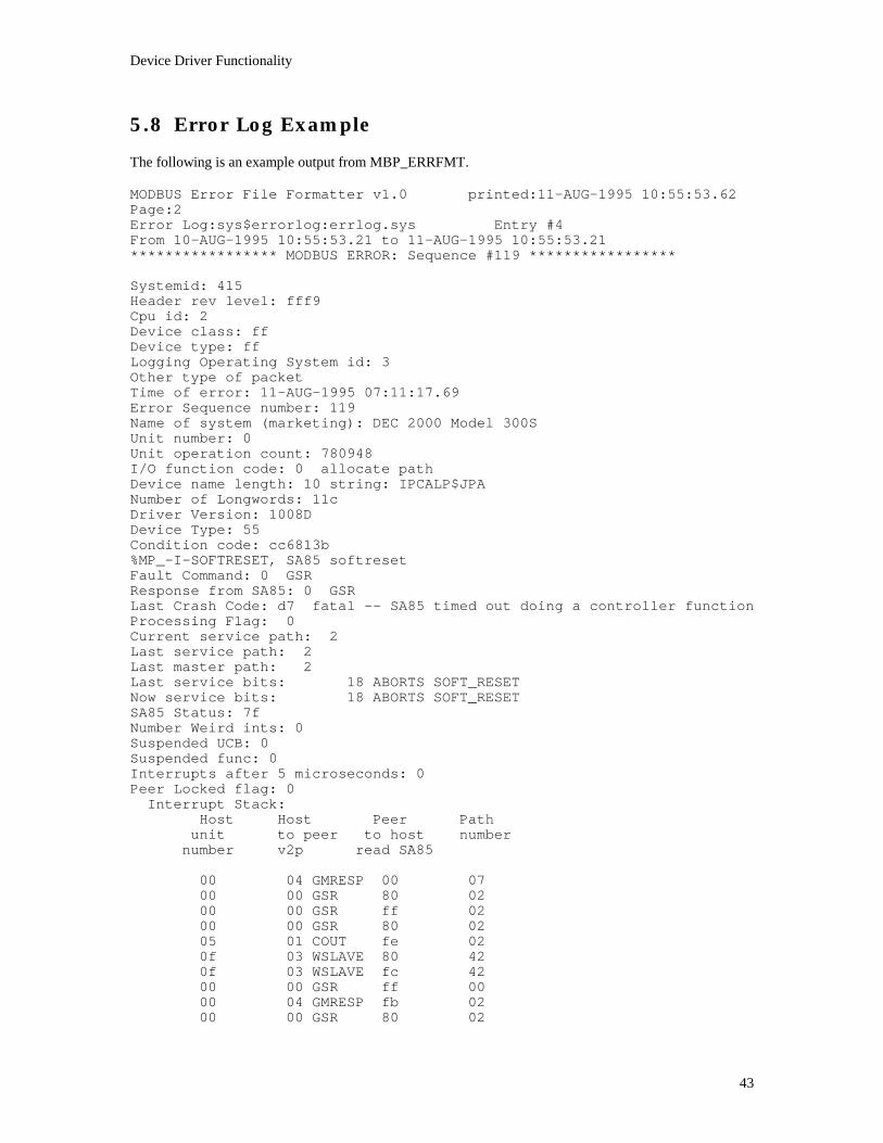
5.8 Error Log ExampleThe following is an example output from MBP_ERRFMT.
MODBUS Error File Formatter v1.0 printed:11-AUG-1995 10:55:53.62Page:2Error Log:sys$errorlog:errlog.sys Entry #4From 10-AUG-1995 10:55:53.21 to 11-AUG-1995 10:55:53.21***************** MODBUS ERROR: Sequence #119 *****************
Systemid: 415Header rev level: fff9Cpu id: 2Device class: ffDevice type: ffLogging Operating System id: 3Other type of packetTime of error: 11-AUG-1995 07:11:17.69Error Sequence number: 119Name of system (marketing): DEC 2000 Model 300SUnit number: 0Unit operation count: 780948I/O function code: 0 allocate pathDevice name length: 10 string: IPCALP$JPANumber of Longwords: 11cDriver Version: 1008DDevice Type: 55Condition code: cc6813b%MP_-I-SOFTRESET, SA85 softresetFault Command: 0 GSRResponse from SA85: 0 GSRLast Crash Code: d7 fatal -- SA85 timed out doing a controller functionProcessing Flag: 0Current service path: 2Last service path: 2Last master path: 2Last service bits: 18 ABORTS SOFT_RESETNow service bits: 18 ABORTS SOFT_RESETSA85 Status: 7fNumber Weird ints: 0Suspended UCB: 0Suspended func: 0Interrupts after 5 microseconds: 0Peer Locked flag: 0
Interrupt Stack:Host Host Peer Path
unit to peer to host numbernumber v2p read SA85
00 04 GMRESP 00 0700 00 GSR 80 0200 00 GSR ff 0200 00 GSR 80 0205 01 COUT fe 020f 03 WSLAVE 80 420f 03 WSLAVE fc 4200 00 GSR ff 0000 04 GMRESP fb 0200 00 GSR 80 02

Device Driver Functionality
44
00 00 GSR ff 0200 01 COUT 80 0102 01 COUT fe 0103 0a RGLOBAL f5 3f05 01 COUT fe 0200 00 GSR ff 0000 04 GMRESP fb 0200 00 GSR 80 0200 00 GSR ff 0200 04 GMRESP 80 0100 04 GMRESP fb 0100 00 GSR ff 0105 01 COUT 80 0205 01 COUT fe 0202 01 COUT 80 0102 01 COUT fe 0100 00 GSR ff 0000 04 GMRESP fb 0200 00 GSR 80 0200 00 GSR ff 0200 04 GMRESP fb 0100 00 GSR 80 0300 00 GSR ff 030e 03 WSLAVE 80 410e 03 WSLAVE fc 4105 01 COUT fe 0202 01 COUT fe 0100 00 GSR ff 0000 04 GMRESP fb 0200 00 GSR 80 0200 00 GSR ff 0200 04 GMRESP 80 0100 04 GMRESP fb 0100 00 GSR 80 0300 00 GSR ff 0300 01 COUT 80 0205 01 COUT fe 0202 01 COUT fe 0100 00 GSR ff 0000 04 GMRESP fb 0200 00 GSR 80 0200 00 GSR ff 0200 04 GMRESP 80 0100 04 GMRESP fb 0100 00 GSR 80 0300 00 GSR ff 0300 02 GSLAVE fd 4100 00 GSR 80 0000 00 GSR ff 0000 00 GSR 80 0000 00 GSR ff 0000 02 GSLAVE fd 4200 00 GSR 80 0000 00 GSR ff 0000 01 COUT 80 0205 01 COUT fe 0202 01 COUT fe 0100 00 GSR ff 0000 04 GMRESP fb 0200 00 GSR 80 0200 00 GSR ff 02

Device Driver Functionality
45
00 04 GMRESP 80 0100 04 GMRESP fb 0100 00 GSR 80 0300 00 GSR ff 0300 01 COUT 80 0205 01 COUT fe 0202 01 COUT fe 0100 00 GSR ff 0000 04 GMRESP fb 0200 00 GSR 80 0200 00 GSR ff 0200 04 GMRESP 80 0100 04 GMRESP fb 0100 00 GSR 80 0300 00 GSR ff 0300 01 COUT 80 0205 01 COUT fe 0202 01 COUT fe 0100 00 GSR ff 0000 04 GMRESP fb 0200 00 GSR 80 0200 00 GSR ff 0200 04 GMRESP 80 0100 04 GMRESP fb 0100 00 GSR 80 0300 00 GSR ff 0300 01 COUT 80 0205 01 COUT fe 0202 01 COUT fe 0100 00 GSR ff 0000 04 GMRESP fb 0200 00 GSR 80 0200 00 GSR ff 0200 04 GMRESP 80 0100 04 GMRESP fb 0100 00 GSR 80 0300 00 GSR ff 0300 01 COUT 80 0205 01 COUT fe 0202 01 COUT fe 0100 00 GSR ff 0000 04 GMRESP fb 0200 00 GSR 80 0200 00 GSR ff 0200 04 GMRESP 80 0100 04 GMRESP fb 0100 00 GSR 80 0300 00 GSR ff 0300 01 COUT 80 0205 01 COUT fe 0202 01 COUT fe 0100 00 GSR ff 0000 04 GMRESP fb 0200 00 GSR 80 0200 00 GSR ff 0200 04 GMRESP 80 0100 04 GMRESP fb 01

Device Driver Functionality
46
gsr_b_dm_paths: 0, 2gsr_b_ds_paths: 0, 0gsr_b_pm_paths: 0, 0gsr_b_ps_paths: 0, 0
GSR Map of global data present:01 02 03 04 05 06 07 08XX XX XX09 10 11 12 13 14 15 16
17 18 19 20 21 22 23 24
25 26 27 28 29 30 31 32XX
33 34 35 36 37 38 39 40
41 42 43 44 45 46 47 48
49 50 51 52 53 54 55 56
57 58 59 60 61 62 63 64XX
LAST COMMAND TO SA85 INFORMATION:
Master Path #1: 2Broadcast Address: ffffffffDestination Address: 3cSource Address: 3fMAC Function: 11Transfer Size (Lo): dTransfer Size (Hi): 0Master Path #2: 2RTR Fail Index: 0Sequence Number: 0MODBUS Function: 8Routing bytes: 3c 00 00 00 00
READ OF SA85 SHARED MEMORY:
Master Path #1: 7Broadcast Address: 4dDestination Address: 4fSource Address: 44MAC Function: 49Transfer Size (Lo): 43Transfer Size (Hi): 4fMaster Path #2: 4eRTR Fail Index: 2cSequence Number: 20MODBUS Function: 49Routing bytes: 43 4f 50 59 52
DUMP: Last Command to SA85
(0000) 3f3cff02 02000d11 003c0000 08000000 03001500 00000004
DUMP: SA85 Shared Memory

Device Driver Functionality
47
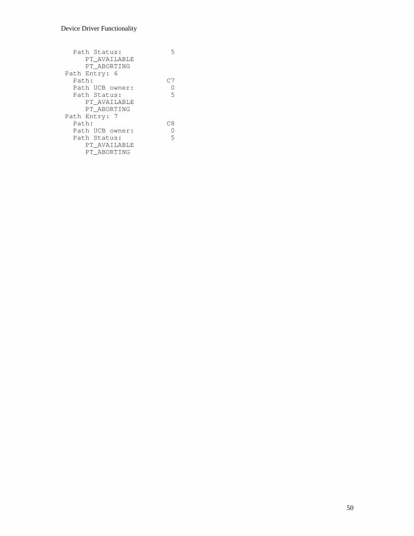
(0000) 444f4d07 4e4f4349 4f43202c 49525950 20544847 20294328Data Master Path tablePath Entry: 0
Path: 1Path UCB owner: 80A2F780Path Status: C
PT_ABORTINGPT_BUSY
Path Entry: 1Path: 2Path UCB owner: 80A4AF00Path Status: C
PT_ABORTINGPT_BUSY
Path Entry: 2Path: 3Path UCB owner: 80A6C680Path Status: C
PT_ABORTINGPT_BUSY
Path Entry: 3Path: 4Path UCB owner: 80A6CEC0Path Status: C
PT_ABORTINGPT_BUSY
Path Entry: 4Path: 5Path UCB owner: 0Path Status: 5
PT_AVAILABLEPT_ABORTING
Path Entry: 5Path: 6Path UCB owner: 0Path Status: 5
PT_AVAILABLEPT_ABORTING
Path Entry: 6Path: 7Path UCB owner: 0Path Status: 5
PT_AVAILABLEPT_ABORTING
Path Entry: 7Path: 8Path UCB owner: 0Path Status: 5
PT_AVAILABLEPT_ABORTING
Data Slave Path tablePath Entry: 0
Path: 41Path UCB owner: 80A63F40Path Status: 8
PT_BUSYPath Entry: 1
Path: 42Path UCB owner: 80A66EC0Path Status: C

Device Driver Functionality
48
PT_ABORTINGPT_BUSY
Path Entry: 2Path: 43Path UCB owner: 80A68400Path Status: 8
PT_BUSYPath Entry: 3
Path: 44Path UCB owner: 0Path Status: 5
PT_AVAILABLEPT_ABORTING
Path Entry: 4Path: 45Path UCB owner: 0Path Status: 5
PT_AVAILABLEPT_ABORTING
Path Entry: 5Path: 46Path UCB owner: 0Path Status: 5
PT_AVAILABLEPT_ABORTING
Path Entry: 6Path: 47Path UCB owner: 0Path Status: 5
PT_AVAILABLEPT_ABORTING
Path Entry: 7Path: 48Path UCB owner: 0Path Status: 5
PT_AVAILABLEPT_ABORTING
Program Master Path tablePath Entry: 0
Path: 81Path UCB owner: 0Path Status: 5
PT_AVAILABLEPT_ABORTING
Path Entry: 1Path: 82Path UCB owner: 0Path Status: 5
PT_AVAILABLEPT_ABORTING
Path Entry: 2Path: 83Path UCB owner: 0Path Status: 5
PT_AVAILABLEPT_ABORTING
Path Entry: 3Path: 84Path UCB owner: 0Path Status: 5

Device Driver Functionality
49
PT_AVAILABLEPT_ABORTING
Path Entry: 4Path: 85Path UCB owner: 0Path Status: 5
PT_AVAILABLEPT_ABORTING
Path Entry: 5Path: 86Path UCB owner: 0Path Status: 5
PT_AVAILABLEPT_ABORTING
Path Entry: 6Path: 87Path UCB owner: 0Path Status: 5
PT_AVAILABLEPT_ABORTING
Path Entry: 7Path: 88Path UCB owner: 0Path Status: 5
PT_AVAILABLEPT_ABORTING
Program Slave Path tablePath Entry: 0
Path: C1Path UCB owner: 0Path Status: 5
PT_AVAILABLEPT_ABORTING
Path Entry: 1Path: C2Path UCB owner: 0Path Status: 5
PT_AVAILABLEPT_ABORTING
Path Entry: 2Path: C3Path UCB owner: 0Path Status: 5
PT_AVAILABLEPT_ABORTING
Path Entry: 3Path: C4Path UCB owner: 0Path Status: 5
PT_AVAILABLEPT_ABORTING
Path Entry: 4Path: C5Path UCB owner: 0Path Status: 5
PT_AVAILABLEPT_ABORTING
Path Entry: 5Path: C6Path UCB owner: 0
Device Driver Functionality
50
Path Status: 5PT_AVAILABLEPT_ABORTING
Path Entry: 6Path: C7Path UCB owner: 0Path Status: 5
PT_AVAILABLEPT_ABORTING
Path Entry: 7Path: C8Path UCB owner: 0Path Status: 5
PT_AVAILABLEPT_ABORTING

$QIO Requests

$QIO Requests
52
6. $QIO/$QIOW Requests� Using $QIO/$QIOW Requests � User Buffers � IO$_ALLOC Allocate Path � IO$_DEALLOC Deallocate Path � IO$_WRITE_MC Write Master Command � IO$_READ_MR Read Master Response � IO$_READ_SC Read Slave Command � IO$_WRITE_SR Write Slave Response � IO$_GET_GD Get Global Data � IO$_PUT_GD Put Global Data � IO$_GET_CS Get Configuration Status Information � IO$_GET_SR Get Service Request Information � IO$_GET_SS Get Driver Status/Statistics � IO$_ABORT Abort Transaction

$QIO Requests
53
6.1 Using $QIO/$QIOW Requests
Both the $QIO and $QIOW calls request that VMS place a specified I/O request on the targeted devicedriver’s input queue. A successful $QIO call queues the request to the driver and allows the applicationprocess to continue while the I/O action progresses. A successful $QIOW call queues the request to thedriver and blocks the process until the I/O action completes.
6.1.1 If the Queue Attempt is Successful
If the queue attempt is successful, the driver will process the request until some form of I/O action iscompleted. An event flag can be specified as a parameter in the request. The flag will be set when the I/Oaction actually completes.
The address of a VMS AST service routine, and a parameter to be passed to the routine can also bespecified as parameters. Upon successful completion of the I/O action, the service routine executes.
6.1.2 Completion of the Request
The final result of completion of the I/O Action will be a condition code value returned in an I/O StatusBlock, indicating the action that was taken by the driver. The address of the status block is a parameterspecified in the $QIO/$QIOW. The application process can examine the condition code to determinewhether the I/O action was as requested. The condition value SS$_NORMAL is returned for successfulcompletion. Other values are returned for unsuccessful completion, such as for the target device beingoffline, or due to a timeout, powerfail, or similar condition. Condition codes are listed for each type ofrequest in this chapter.
Some requests also transfer information to or from a buffer. The buffer address and length are parametersthat are specified in the request.
6.1.3 If the Queue Attempt is Unsuccessful
If an error occurs in processing a $QIO/$QIOW request before it is queued to the driver, VMS returns anerror condition code as listed in the VMS Programming Manual, Volume 4B - System Services.
If an event flag was specified in the request, it will be set to show the termination of the request, but the I/OStatus Block will not be filled and any specified service routine will not execute.

$QIO Requests
54
6.1.4 Call Format
The format and arguments for the $QIO and $QIOW system services are as follows. Arguments in brackets[ ] are optional:
$QIO [W]$QIO [W]$QIO [W]$QIO [W] [efn],chan,[efn],chan,[efn],chan,[efn],chan, funcfuncfuncfunc [,iosb][,iosb][,iosb][,iosb] [,astadr][,astadr][,astadr][,astadr] [,astprm][,astprm][,astprm][,astprm][,p1][,p1][,p1][,p1] [,p2][,p2][,p2][,p2] [,p3][,p3][,p3][,p3] [,p4][,p4][,p4][,p4] [,p5][,p5][,p5][,p5] [,p6][,p6][,p6][,p6]
The arguments are outlined below. For a more detailed description refer to your VMS ProgrammingManual, Volume 4B - System Services.
efn An event flag number specified by the user. The event flag will be set when theI/O operation actually completes.
The event flag will also be set if the $QIO service terminates before queuing theI/O request (for example, if an illegal argument is specified in the request).
chan The I/O channel number previously assigned to the device by $ASSIGN.
func The I/O function code and modifier specifying the operation to be performed. Asymbolic list of codes and modifiers is contained in this chapter. Their valuesare listed in Appendix C.
iosb The address of the I/O status block to receive the final completion status of theI/O operation.
If an error occurs in attempting to queue the request to the device driver, theIOSB fields will not be filled.
astadr The address of the entry mask of the service routine to be executed when the I/Ooperation completes.
If the $QIO service terminates before queuing the I/O request, the service routinewill not execute.
astprm The parameter to be passed to the specified service routine.
p1 - p6 Device and I/O function dependent parameters. Parameters that are bufferpointers are standard VAX 32-bit virtual addresses. All other parameters are 16-bit unsigned integers.
$QIO Requests
55
6.1.5 Physical I/O Access Privilege
All of the function codes used with the host-based devices are in the VMS physical I/O range of values,requiring the issuing process to have physical I/O privilege (PHY_IO). This allows the VMS systemadministrator some control over which users can access the device driver and Modbus Plus network.
If a user without physical I/O privilege issues a $QIO to the driver, the I/O operation is rejected by the$QIO system service, which returns a condition value of SS$_NOPRIV. This prevents a process lackingthe physical I/O privilege from communicating with a Modbus Plus device.
6.1.6 $QIO/$QIOW Function Codes and Modifiers
All VMS function codes begin with the characters IO$_ to which is appended a suffix describing thespecific type of I/O request intended by the function. All of the $QIO/$QIOW functions recognized by thedevice driver use this format. They are contained in the C header file mp_funcs.h. Their values are listed inAppendix C.
Function modifiers are values which can be ORed together with the function code to request an operationalfeature of the function. All VMS function modifiers begin with the characters IO$M_ to which is appendeda suffix that describes the modifier. For example, the modifier IO$M_ERASE specifies that the statisticscounters are to be zeroed after being returned from the request. Modifiers, if used, are listed in the detaileddescription of each call in this chapter.
6.1.7 The IOSB Argument
One of the arguments you can specify is the address of an I/O Status Block (IOSB) to receive the driver’scompletion code and other information about the completed request. It is strongly recommended that youinclude this argument and check the IOSB upon completion of the request. Otherwise, errors occurring inthe I/O operation can go undetected. Also note that the path number returned in the IOSB can be helpfulfor program debugging. The IOSB is described on the next page.
6.1.8 The P1-P6 Parameters
The $QIO/$QIOW call can include up to six device-dependent parameters, called P1 through P6. The useof these parameters differs for the specific $QIO/$QIOW and is shown in the detailed description of eachcall in this chapter.

$QIO Requests
56
6.1.9 The I/O Status Block (IOSB)
The I/O Status Block is an optional argument [iosb] that you can include in $QIO/$QIOW calls in order toreceive detailed information on the status of the request to the device driver. Modicon devices use a differIOSB format from that used by typical $QIO/$QIOW calls. The IOSB format is shown in Figure 6.
Figure 6 - I/O Status Block (IOSB) Format
VMS clears the IOSB during initial processing of the call, and the device driver fills the appropriate fieldswhen it completes the request. If the call fails before it is queued to the driver, the IOSB will not be filledand the condition code value returned by VMS will indicate the error.
If the queuing succeeds, SS$_NORMAL is returned to the request. At that time the driver will process therequest and will return its own condition code in the IOSB indicating the completion status of the I/Ooperation. SS$_NORMAL is returned as the IOSB condition code if the I/O operation is completednormally.
The IOSB condition code if the I/O operation is completed normally.
The IOSB condition code is returned for all requests completed by the driver. Linking the message fileMP_MESSAGE.OBJ (on your TK50 tape) with your application allows error reporting using standardVMS facilities. A listing of condition codes is provided in Appendix C.
Use of the other three IOSB fields is dependent upon the specific $QIO/$QIOW:
� Transfer Count (IOSB bytes 4 and 5) is filled by a data input or output request, indicating the quantityof bytes transferred to or from the user buffer.
� Crash Code (IOSB byte 6) can only be returned by a request to a controller. If a controller crash
occurs, the code MP$_CTRLCRASH is returned in the first word of the IOSB, and the specific crashcode is placed in this field. A listing of crash codes is provided in Appendix C.
� Path Number (IOSB byte 7) returns the path number currently assigned to the I/O channel (if any) at
the time the request completes.
TransferCount*
CrashCode*
PathNumber*
IOSBPARAMETERADDRESS
BYTES OFFSET:
DriverCondtion Code
+4 +6 +8
FIELDS MARKED WITH ASTERICK * DEPEND UPON THE CALLTYPE. IF NOT APPLICABLE, WILL BE ZERO-FILLED.

$QIO Requests
57
6.1.10 Device Command Timeouts
Command timeouts are automatically used with each device request issued by the driver to ensure that thedevice makes a timely response to the command. The driver runs an internal timer to monitor completion ofeach request to the device. This timer does not require that network activity occurs. Your application hasno direct control over this type of timer.
A failure to complete a command within the expected time is considered a fatal error. If this occurs, the$QIO/$QIOW is completed with a condition code of MP$_CTRLTMO. Error handling for this condition isdescribed in Chapter 4.
6.1.11 User Timeouts
A user timeout is an argument specified in P5 of certain $QIO/$QIOW requests. It specifies the maximumamount of time, in seconds, that can elapse between the driver initiating an I/O operation and itscompletion. Only I/O read requests use this timeout parameter.
Any $QIO/$QIOW function that can immediately be completed by the driver (such as IO$_GET_SS - GetDriver Status/Statistics) does not require a user timer. Any function that can immediately be completed bythe device (such as $IO_GET_GD - Get Global Data) also does not require a user timer. In such cases thedevice command timeout used by the device driver ensures that the command completes. User timeoutsapply only to requests that require a response from a remote node in order to complete (such asIO$_READ_MR - Read Master Response, and similar requests).
The timing interval starts when the driver actually begins executing the request. While a request remainsqueued to the driver, the timing interval is not started for that request. Thus the interval reflects the actualexecution time to be allowed for the I/O transaction.
Using the Timing Interval: User timeouts are driven by an asynchronous timer with a timing interval ofone second. To ensure achieving at least one full timer interval, the specified timing value should be onesecond more than the desired timeout. The specified value is therefore a maximum value with a toleranceof ‘plus zero, minus one’ second.
For example, to have a timeout of at least one second, a value of two should be used in the argument. Avalue of one would cause the timeout to occur at any time from zero to one second, because timing startsasynchronously at any point in the timer’s current cycle and the timeout would occur at the end of thatcycle. A value of two causes the timeout to occur at a point between one and two seconds. If you specify avalue of one, the driver will change it to two.
If you specify a value of zero, the user timeout function will be disabled for that $QIO/$QIOW request.The implication of a zero timeout value is that the request will remain pending until it completes. Meaningthat an uncompleted request would remain pending indefinitely and potentially cause the application tohang.
A sufficiently large value can be specified for the timeout argument to effectively disable the user timeout.The argument is a 16-bit unsigned value, allowing a maximum user timeout period of 65,535 seconds (18.2hours).
If a user timeout occurs the request is completed with a returned condition code of SS$_TIMEOUT. Atimed-out operation is not retried by the driver.

$QIO Requests
58
6.1.12 Using Global Data
Global data is accessed using the Get Global Data and put Global Data $QIO/$QIOW requests.
Getting Global Data from a Remote Node
When a process issues a Get Global Data request for a node other than the local node is the Modbus Plusdevice that is processing the request), the data is read from a global data image area that is maintained in thelocal node. This area contains a copy of the most recent global data received from the other network nodes.
The act of reading the data from the local node’s image area destroys the copy of the data stored in the localnode. The data is destroyed only for the specific node for which global data was accessed. The data imagestored for the other nodes is not affected. The specific node’s global data image will be refreshed when thatnode transmits a new token contained a new copy of its global data, and that data is received by the localnode. The new data can be read by issuing another Get Global Data $QIO/$QIOW.
When the local device’s copy of a remote node’s global data is read, the remote node’s data then becomesunavailable until a new token with global data is received from that node. Get Global Data calls for thesame node during this interim will return MP$_NOGLOBAL (data for the other nodes is still available).This sequence assures that the call receives the most recent data.
The MP$_NOGLOBAL status would also returned if the remote node were not communicating at all. Thusa process may want to retry the Get Global Data request if the MP$_NOGLOBAL status is returned.
Getting Global Data from the Local Node
When the local device’s own global data is read by the request, the global data then becomes unavailablefor a subsequent Get Global Data call until the local device next passes the network token.MP$_NOGLOBAL is returned until the token pass occurs.
Putting Global Data
The only node to which the Put Global Data request can be issued is the local node (the local node is theModbus plus device that is processing the request). When a process wishes to change the local node’sglobal data, it supplies a pointer to the new data and a parameter for its length. The new data overwritesand replaces the old data, if any.
The size is specified in bytes and must be an even quantity since the Modbus Plus peer processor in thedevice only deals with words of global data. A size of zero is valid and does not return an error.
The local node continues to send its global data with each token pass on the network until it is specificallystopped from doing so by the application. To stop sending global data, the application should issue anotherPut Global Data request with a size parameter of zero.

$QIO Requests
59
6.1.13 Configuration Status Information
The $QIO/$QIOW function, Get Configuration Status Information, retrieves the current configuration statusfrom a selected device and places it into an user buffer. The information returned includes the device type,its peer processor software version, its communication status and active station table, and informationpertaining to token counts and rotation time. Also included are counters that report successful messagepackets, retries, and errors.
The request uses an optional function modifier that will clear the counters after retrieving their informationto the user buffer.
The device driver automatically issues this command to each local device approximately every two secondsto serve as a watchdog function. A device not receiving the command within this time will set a crash errorand will report it for subsequent requests to the device. This process is independent of any $QIO/$QIOWrequests (including Get Configuration Status) issued in the application.
6.2 User Buffers
$QIO/$QIOW requests that transfer input or output data require the specification of user buffer address andlength parameters. The descriptions in this chapter show the layout of the required user buffer. ‘Input’requests show the purpose of each field contained in the buffer. ‘Output’ requests show the purpose of eachfield and identify those which the driver will fill, and those which the user must fill with data.
The length of the buffer must include the entire information packet that is to be transferred. Note that thislength must be large enough to include information that is supplied automatically by the device driver aswell as by the user. The minimum size is 16 bytes and the maximum is 270. Data input requests with alength below the minimum required will be rejected with a condition code of MP$_BADSIZE. Data outputrequests that are either below the minimum or above the maximum required will likewise be rejected with acondition code of MP$_BADSIZE.
Note that an input buffer that meets the driver’s minimum requirements may still prove to be too small forthe size of the received message. Programmers must ensure that an input buffer specified in a request islarge enough to hold the expected contents of the input operation. If the buffer will not hold the actualinput, the driver will fill the buffer, truncate any input that would otherwise overflow it, and return thecondition code MP$_BUFFEROVF. The transfer count returned in the IOSB will always reflect the actualquantity of bytes transferred to the input buffer.

$QIO Requests
60
6.2.1 The User Buffer Format for a Normal Transaction
The user buffer for Global Data calls contain the data bytes as read or written. The buffer for ConfigurationStatus and Service Request Information calls is specific to those calls and is shown in detail in theindividual call descriptions.
The user buffer format for the $QIO/$QIOW requests IO$_WRITE_MC, IO$_READ_MR,IO$_READ_SC, and IO$WRITE_SR is similar for all of these requests. It consists of two parts: a 15-byteheader portion, which contains Modbus Plus packet information, followed by the Modbus message portion.
Some of the header fields will be filled automatically by the driver, while others must be filled by the userapplication. The individual descriptions of these calls show the purpose of each byte in the header and thesource of its contents. The message portion is filled or read entirely by the user application.

$QIO Requests
61
The header portion: This is the format of the 15-byte header portion of the buffer for Master or Slave pathtransactions:
Bytes Contents
1 For WRITE_MC and READ_MR calls: the master output path.For READ_SC and WRITE_SR calls: the slave input path.The byte contains the path type combined with the path number, in the form ‘tn’ where ‘t’ isthe path and ‘n’ the path number. The path types are (in hex): DM=0n, DS=4n, PM=8n,PS=Cn. Path numbers are 1 to 8. For example, 01 specifies Data Master path 1;42 specifiesData Slave path 2.
2 Broadcast address: the field is always hex FF.
3 Destination address: the Modbus Plus address of the destination node.
4 Source address: the Modbus Plus address of the source node.
5 MAC function code: the Modbus Plus MAC layer function code.
6 Message data byte count: low-order byte.
7 Message data byte count: high-order byte. When combined with the low-order byte, theresulting value is 7 less than the number of bytes in the user buffer.
8 Master path: the source node’s master path type and number used in the transaction.
9 For WRITE_MC and READ_SC calls: reserved, always 0.For READ_MR and WRITE_SR calls: the slave path login status: 1 if the master path usedin the transaction has login privilege on the slave node, 0 if it does not.
10 Modbus Plus transaction sequence number. The exception is for station managementtransactions in which this byte contains a retry count used to complete the transaction.
11-15 Routing bytes 1 through 5 of the Modbus Plus routing path.
The message portion: The Modbus message portion of the buffer begins with the Modbus function code,contained in the first byte of the message. Any data which follows the function code must be encoded in theModbus RTU format of two hexadecimal characters per eight-bit byte. Up to 255 bytes can be contained inthe message portion, including the command byte.
Note that the first byte of the message is not the ‘slave address’ as used in the standard Modbus protocol.For further information about the message contents used for each type of Modbus command, refer toAppendix B of this guide.

$QIO Requests
62
6.2.2 The User Buffer Format for a Routing Failure
If a routing failure occurs in a remote node, the header and message contents returned to the user buffer willdiffer slightly from the expected data contents. The differences are listed below.
Differences in the header portion:
Byte Contents
4 This byte contains the MAC function code for ‘routing-failed’. The least significant five bitsof the code will be 10011.
8 Instead of the slave login status, this byte contains the routing failure index. This index valueis 1 to 5, indicating the Modbus Plus routing path byte (1 to 5) in the original request at whichthe routing error occurred.
15 Instead of the first byte of the message, this byte contains the device type of the failed node. Itidentifies the type of device that generated the routing failure message. The device types are:
0 Unknown device type1 Programmable Controller2 Bridge Multiplexer3 Network Adapter4 Bridge Plus5 Peer I/O
16 Instead of the second byte of the message, this byte contains the routing failure error condition.This value is the specific condition that caused the routing failure. The error conditions are (inhex):
01 No response received02 Program access denied03 Node offline04 Exception response received05 Bridge Plus paths busy06 Slave device down07 Bad destination address08 Invalid route10 Slave rejected message20 Forgotten transaction40 Invalid path80 Unsupported MAC function

$QIO Requests
63
6.3 IO$_ALLOC Allocate Path
This request allocates an available path to this channel and device, setting the path state to Allocated. Therequest specifies two characteristics of the requested path: Data or Program, and Master or Slave. ForMaster path requests, you can request a specific path or have the driver search for and supply an availablepath. For Slave path requests, you must request a specific path, which must be currently Available (notalready Allocated or Busy).
During processing of the request, an Abort Transaction command is sent to the device to ensure that thepath is clear at the device level.
The path number of the allocated path is returned to the IOSB.
Restrictions
If a specific path is requested, the targeted device must support the requested path number or a bad patherror will be returned (MP$_BADPATH).
A path of the type requested (or the specific path requested) must be Available or a path not available errorwill be returned (MP$_PATHUNAVL).
The I/O channel must not have another path allocated, or a path allocation error will be returned(MP$_PATHALLOC).
Function Modifiers
None.
Parameters
P1 The requested path number, where:
Bit 1 -6: Path number. Zero if the driver is to locate and supply an available Master path.
Bit 7: 0 = Master, 1 = Slave.
Bit 8: 0 = Data, 1 = Program.
Device Commands Issued
Abort Transaction
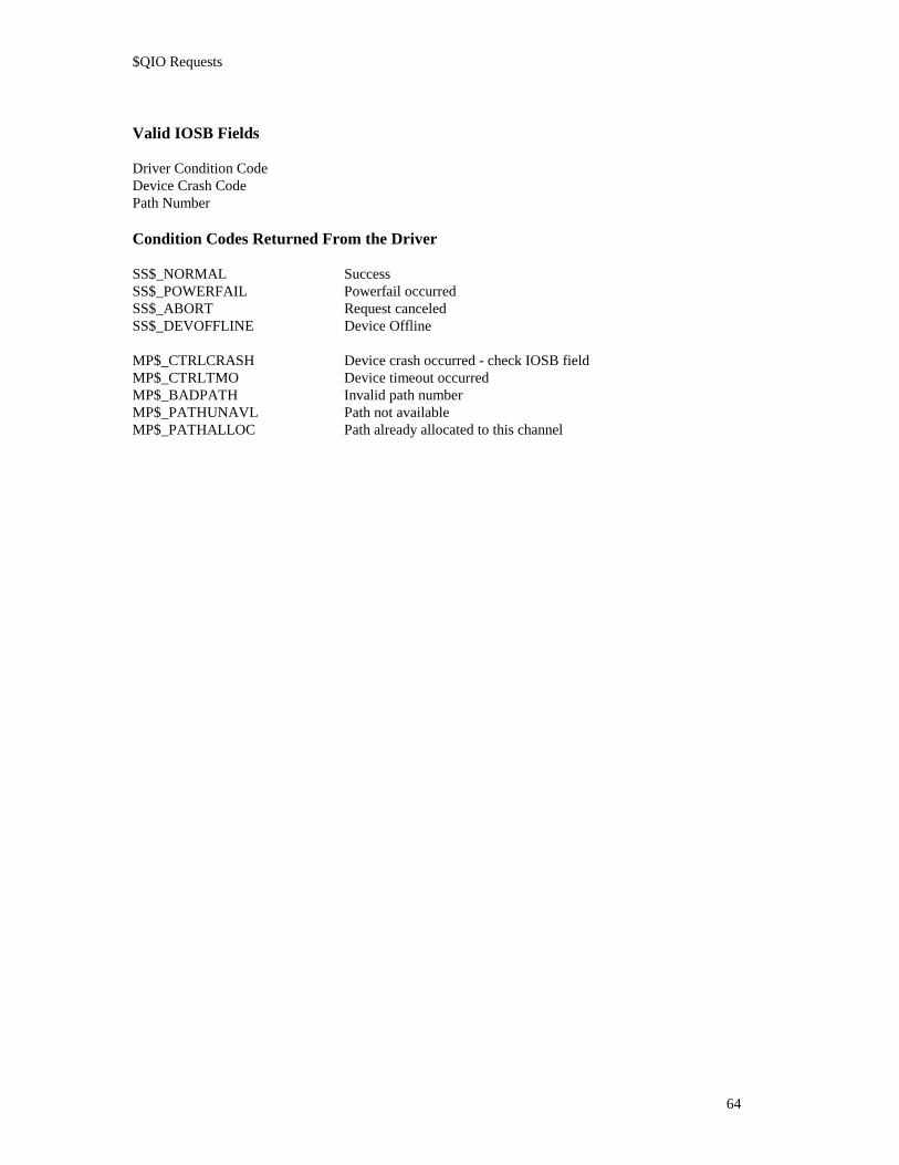
$QIO Requests
64
Valid IOSB Fields
Driver Condition CodeDevice Crash CodePath Number
Condition Codes Returned From the Driver
SS$_NORMAL SuccessSS$_POWERFAIL Powerfail occurredSS$_ABORT Request canceledSS$_DEVOFFLINE Device Offline
MP$_CTRLCRASH Device crash occurred - check IOSB fieldMP$_CTRLTMO Device timeout occurredMP$_BADPATH Invalid path numberMP$_PATHUNAVL Path not availableMP$_PATHALLOC Path already allocated to this channel

$QIO Requests
65
6.4 IO$_DEALLOC Deallocate Path
This request deallocates a previously allocated path to the specified channel and device, setting the pathstate to Available.
During processing of the request, an Abort Transaction command is sent to the device to ensure that thepath is clear at the device level.
Restrictions
A path must already be allocated to the current I/O channel or a path error will be returned(MP$_NOPATH).
Function Modifiers
None.
Parameters
None.
Device Commands Issued
Abort Transaction
Valid IOSB Fields
Driver Condition CodeDevice Crash Code
Condition Codes Returned From the Driver
SS$_NORMAL SuccessSS$_ABORT Request canceledSS$_DEVOFFLINE Device offline
MP$_CTRLCRASH Device crash occurred - check IOSB fieldMP$_CTRLTMO Device timeout occurredMP$_NOPATH No path allocated

$QIO Requests
66
6.5 IO$_WRITE_MC Write Master Command
This request writes a Master command to the specified device Master path, which must have beenpreviously Allocated. This transitions the path state from Allocated to Busy.
Restrictions
A path must already be allocated to the current I/O channel or path error will be returned (MP$_NOPATH).
The path must be in the Allocated state or a path state error will be returned (MP$_PATHSTAT).
The path must be a Master path or a path type error will be returned (MP$_PATHTYP).
The user output buffer (P1) must not be less than the minimum size or greater than the maximum sizerequirements of the Modbus Plus protocol or a size error will be returned (MP$_BADSIZE).
Function Modifiers
None.
Parameters
P1 The VAX starting address of the output buffer that contains the master command and headerinformation required by the device.
P2 The size in bytes of the P1 buffer. The minimum size is 16 bytes to accommodate the 15-byteheader and one-byte Modbus command. The maximum size is 270 bytes to accommodate the 15-byte header and Modbus message of 255 bytes.
Device Commands Issued
Put Master Command to Output Path
Valid IOSB Fields
Driver Condition CodeTransfer CountDevice Crash CountPath Number

$QIO Requests
67
User Buffer Format
P1 Command Output Buffer (data supplier in parentheses):
Byte 01 Master Path (driver)Byte 02 Broadcast Address (driver)Byte 03 Destination Address (driver)Byte 04 Source Address (driver)Byte 05 MAC Function (driver)Byte 06 Data Byte Count, Low (driver)Byte 07 Data Byte Count, High (driver)Byte 08 Master Path (driver)Byte 09 Reserved (driver)Byte 10 Sequence Number (driver)Byte 11 Routing Byte 1 (user)Byte 12 Routing Byte 2 (user)Byte 13 Routing Byte 3 (user)Byte 14 Routing Byte 4 (user)Byte 15 Routing Byte 5 (user)Byte 16 Modbus Command Byte 1 - the Modbus function code (user). . .Byte n Last Modbus Command Byte (user)
Condition Codes Returned From the Driver
SS$_NORMAL SuccessSS$_POWERFAIL Powerfail occurredSS$_ABORT Request canceledSS$_DEVOFFLINE Device offline
MP$_BADSIZE Invalid user buffer sizeMP$_CTRLCRASH Device crash occurred - check IOSB fieldMP$_CTRLTMO Device timeout occurredMP$_NOPATH No path allocatedMP$_PATHTYP Invalid path type for requested operationMP$_PATHSTAT Path state error occurred

$QIO Requests
68
6.6 IO$_READ_MR Read Master Response
This request reads a Master response from the specified device master path. The user must be reading aresponse to a Write Master command that was previously written on this path. This transitions the pathstate from Busy to Allocated.
Restrictions
A path must already be allocated to the current I/O channel or a path error will be returned(MP$_NOPATH).
The path must be in the Busy state or a path state error will be returned (MP$_PATHSTAT).
The path must be a Master path or a path type error will be returned (MP$_PATHTYP).
The user input buffer (P1) must not be less than the minimum size requirements of the Modbus Plusprotocol or a size error will be returned (MP$_BADSIZE).
If the input buffer is not large enough to contain the input during processing a buffer overflow error will bereturned (MP$_BUFFEROVF).
Function Modifiers
None.
Parameters
P1 The VAX starting address of the input buffer to receive the Master response and headerinformation returned by the device.
P2 The size in bytes of the P1 buffer.
P5 The user timeout value, in seconds, to apply to this request.
Device Commands Issued
Get Service RequestGet Master Response from Output Path
Valid IOSB Fields
Driver Condition CodeTransfer CountDevice Crash CodePath Number
User Buffer Format
See the description on the following pages for the P1 Response Input Buffer formats for a normal responseand for a routing error response.
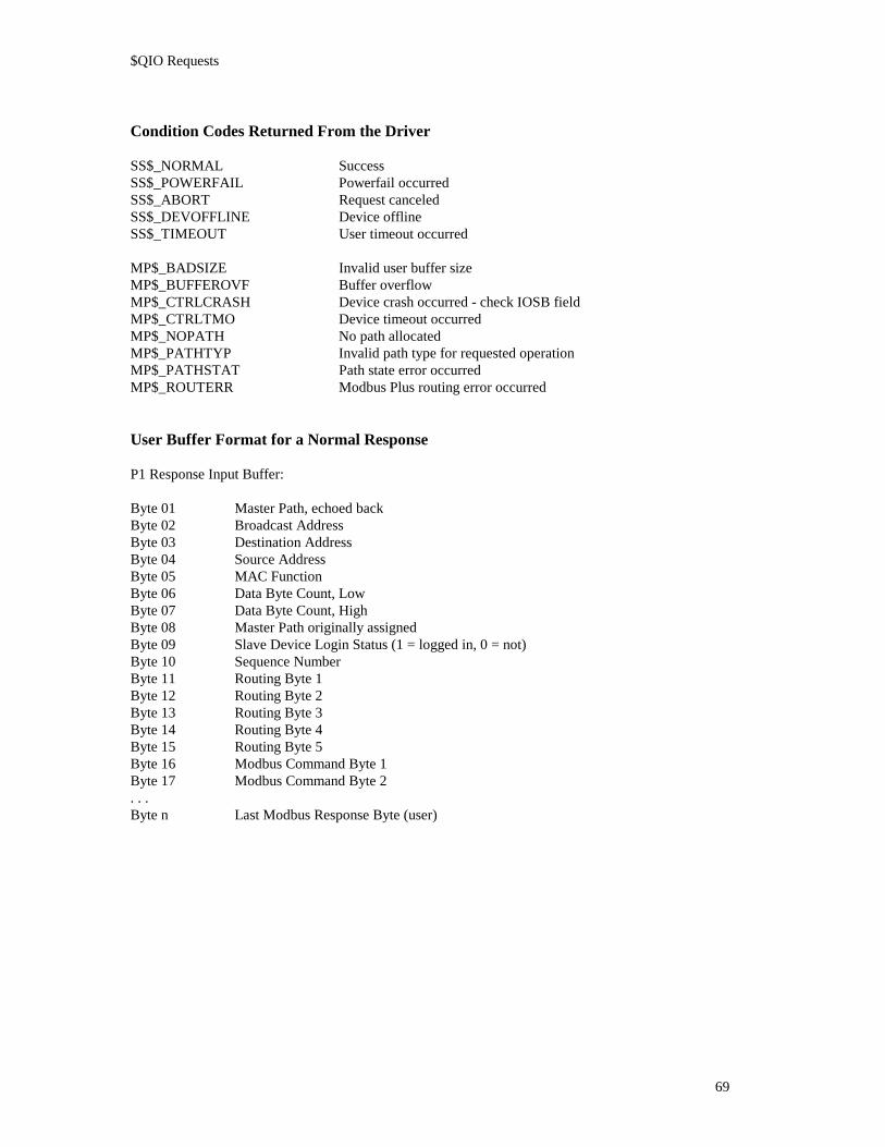
$QIO Requests
69
Condition Codes Returned From the Driver
SS$_NORMAL SuccessSS$_POWERFAIL Powerfail occurredSS$_ABORT Request canceledSS$_DEVOFFLINE Device offlineSS$_TIMEOUT User timeout occurred
MP$_BADSIZE Invalid user buffer sizeMP$_BUFFEROVF Buffer overflowMP$_CTRLCRASH Device crash occurred - check IOSB fieldMP$_CTRLTMO Device timeout occurredMP$_NOPATH No path allocatedMP$_PATHTYP Invalid path type for requested operationMP$_PATHSTAT Path state error occurredMP$_ROUTERR Modbus Plus routing error occurred
User Buffer Format for a Normal Response
P1 Response Input Buffer:
Byte 01 Master Path, echoed backByte 02 Broadcast AddressByte 03 Destination AddressByte 04 Source AddressByte 05 MAC FunctionByte 06 Data Byte Count, LowByte 07 Data Byte Count, HighByte 08 Master Path originally assignedByte 09 Slave Device Login Status (1 = logged in, 0 = not)Byte 10 Sequence NumberByte 11 Routing Byte 1Byte 12 Routing Byte 2Byte 13 Routing Byte 3Byte 14 Routing Byte 4Byte 15 Routing Byte 5Byte 16 Modbus Command Byte 1Byte 17 Modbus Command Byte 2. . .Byte n Last Modbus Response Byte (user)

$QIO Requests
70
User Buffer Format for a Routing Error Response
P1 Response Input Buffer
Byte 01 Master Path, echoed backByte 02 Broadcast AddressByte 03 Destination AddressByte 04 Source AddressByte 05 MAC Function, set to xxx10011 binary = routing failedByte 06 Data Byte Count, LowByte 07 Data Byte Count, HighByte 08 Master Path originally assignedByte 09 Routing Path Failure Index: 1-5, indicating the routing path byte containing node address
that returned the errorByte 10 Sequence NumberByte 11 Routing Byte 1Byte 12 Routing Byte 2Byte 13 Routing Byte 3Byte 14 Routing Byte 4Byte 15 Routing Byte 5Byte 16 Failed Node Type: 0 Unknown device type
1 Programmable Controller2 Bridge Multiplexer3 Network Adapter4 Bridge Plus5 Peer I/O
Byte 17 Routing Failure Error Condition:
01 No response received02 Program access denied03 Node offline04 Exception response received05 Bridge Plus paths busy06 Slave device down07 Bad destination address08 Invalid route10 Slave rejected message20 Forgotten transaction40 Invalid path80 Unsupported MAC function

$QIO Requests
71
6.7 IO$_READ_SC Read Slave Command
This request reads a Slave command from the specified device slave path which must have been previouslyAllocated. This transitions the path state from Allocated to Busy.
Restrictions
A path must already be allocated to the current I/O channel or a path error will be returned(MP$_NOPATH).
The path must be in the Allocated state or a path state error will be returned (MP$_PATHSTAT).
The path must be a Slave path or a path type error will be returned (MP$_PATHTYP).
The user input buffer (P1) must not be less than the minimum size requirements of the Modbus Plusprotocol or a size error will be returned (MP$_BADSIZE).
If the input buffer is not large enough to contain the input during processing a buffer overflow error will bereturned (MP$_BUFFEROVF).
Function Modifiers
None.
Parameters
P1 The VAX starting address of the input buffer to receive the Slave command and headerinformation returned by the device.
P2 The size in bytes of the P1 buffer.
P5 The user timeout value, in seconds, apply to this request.
Device Commands Issued
Get Service RequestGet Slave Command from Input Path
Valid IOSB Fields
Driver Condition CodeTransfer CountDevice Crash CodePath Number

$QIO Requests
72
User Buffer Format
P1 Command Input BufferByte 01 Slave Path (Hex: 41, 42,...,48)Byte 02 Broadcast AddressByte 03 Destination AddressByte 04 Source AddressByte 05 MAC FunctionByte 06 Data Byte Count, LowByte 07 Data Byte Count, HighByte 08 Master PathByte 09 ReservedByte 10 Sequence NumberByte 11 Routing Byte 1: your node addressByte 12 Routing Byte 2: the slave path numberByte 13 Routing Byte 3: 0Byte 14 Routing Byte 4: 0Byte 15 Routing Byte 5: 0Byte 16 Modbus Command Byte 1Byte 17 Modbus Command Byte 2. . .Byte n Last Modbus Response Byte
Condition Codes Returned From the Driver
SS$_NORMAL SuccessSS$_POWERFAIL Powerfail occurredSS$_ABORT Request canceledSS$_DEVOFFLINE Device offlineSS$_TIMEOUT User timeout occurred
MP$_BADSIZE Invalid user buffer sizeMP$_BUFFEROVF Buffer overflowMP$_CTRLCRASH Device crash occurred - check IOSB fieldMP$_CTRLTMO Device timeout occurredMP$_NOPATH No path allocatedMP$_PATHTYP Invalid path type for requested operationMP$_PATHSTAT Path state error occurred

$QIO Requests
73
6.8 IO$_WRITE_SR Write Slave Response
This request writes a Slave response to the specified device master path, which must have been previouslyAllocated. The user must be responding to a Slave command that was previously read on this path. Thistransitions the path state from Busy to Allocated.
Restrictions
A path must already be allocated to the current I/O channel or a path error will be returned(MP$_NOPATH).
The path must be in the Busy state or a path state error will be returned (MP$_PATHSTAT).
The path must be a Slave path or a path type error will be returned (MP$_PATHTYP).
The user output buffer (P1) must not be less than the minimum size or greater than the maximum sizerequirements of the Modbus Plus protocol or a size error will be returned (MP$_BADSIZE).
Function Modifiers
None.
Parameters
P1 The VAX starting address of the input buffer to receive the Slave command and headerinformation returned by the device.
P2 The size in bytes of the P1 buffer.
Device Commands Issued
Put Slave Response to Input Path.

$QIO Requests
74
Valid IOSB Fields
Driver Condition CodeTransfer CountDevice Crash CodePath Number
User Buffer Format
See the description for the P1 Response Input Buffer formats for sending a normal response and for sendinga routing error response.
Condition Codes Returned From the Driver
SS$_NORMAL SuccessSS$_POWERFAIL Powerfail occurredSS$_ABORT Request canceledSS$_DEVOFFLINE Device offline
MP$_BADSIZE Invalid user buffer sizeMP$_CTRLCRASH Device crash occurred - check IOSB fieldMP$_CTRLTMO Device timeout occurredMP$_NOPATH No path allocatedMP$_PATHTYP Invalid path type for requested operationMP$_PATHSTAT Path state error occurred
User Buffer Format for a Normal Response
If a process wishes to return a normal response, the following format is used for the P1 Response InputBuffer (data supplier in parentheses):
Byte 01 Master Path (driver)Byte 02 Broadcast Address (driver)Byte 03 Destination Address (driver)Byte 04 Source Address (driver)Byte 05 MAC Function (driver)Byte 06 Data Byte Count, Low (driver)Byte 07 Data Byte Count, High (driver)Byte 08 Master Path (driver)Byte 09 Slave Path Login Status: 1 = logged in, 0 = not (user)Byte 10 Sequence Number (driver)Byte 11 Routing Byte 1: (driver)Byte 12 Routing Byte 2: (driver)Byte 13 Routing Byte 3: (driver)Byte 14 Routing Byte 4: (driver)Byte 15 Routing Byte 5: (driver)Byte 16 Modbus Command Byte 1 (user)Byte 17 Modbus Command Byte 2 (user). . .Byte n Last Modbus Response Byte (user)

$QIO Requests
75
User Buffer Format for a Routing Error Response
If a process wishes to return a Modbus Plus routing error rather than a regular response, an alternativeformat is used for the P1 Response Input Buffer:
Byte 01 Master Path (driver)Byte 02 Broadcast Address (driver)Byte 03 Destination Address (driver)Byte 04 Source Address (driver)Byte 05 MAC Function (driver)Byte 06 Data Byte Count, Low (driver)Byte 07 Data Byte Count, High (driver)Byte 08 Master Path (driver)Byte 09 Routing Path Failure Index: must be set to 2(user)Byte 10 Sequence Number (driver)Byte 11 Routing Byte 1: (driver)Byte 12 Routing Byte 2: (driver)Byte 13 Routing Byte 3: (driver)Byte 14 Routing Byte 4: (driver)Byte 15 Routing Byte 5: (driver)Byte 16 Failed Node type: must be set to 3 (user)Byte 17 Routing Failure Error Condition: (user)
01 No response received02 Program access denied03 Node offline04 Exception response received05 Bridge Plus paths busy06 Slave device down07 Bad destination address08 Invalid route10 Slave rejected message20 Forgotten transaction40 Invalid path80 Unsupported MAC function

$QIO Requests
76
6.9 IO$_GET_GD Get Global Data
This request retrieves the global data for the specified Modbus Plus node and places it in the user buffer.
The format of global data returned from this request is defined by the application. Note that the byte orderfor global data is different from that for master and slave read/write buffers. Examples are shown later inthis section.
When the local device’s own global data is read by the request, the global data then becomes unavailablefor a subsequent Get Global Data call until the local device passes the network token. When the local copyof a remote node’s global data is read, the remote node’s data then becomes unavailable until a new tokenwith global data is received from that node. Get Global Data calls for the same node during this interimwill return MP$_NOGLOBAL (data for the other nodes is still available). This sequence assures that thecall receives the most recent data.
Restrictions
The specified node address must be from 1 to 64 or node address error will be returned(MP$_BADNODE).
The input buffer size is specified as a byte count from 1 to 64. The size must be an event number of bytesor a bad size error will be returned (MP$_BADSIZE).
If the input buffer is not large enough to contain the input during processing a buffer overflow error will bereturned (MP$_BUFFEROVF).
The local device must have received global data from the specified node or a no global data error will bereturned (MP$_NOGLOBAL).
Function Modifiers
None.
Parameters
P1 The VAX starting address of the input buffer to receive the global data.
P2 The size in bytes of the P1 buffer from 1 to 64.
P3 The Modbus Plus address of the target node.
Device Commands Issued
Get Service RequestGet Global Data

$QIO Requests
77
Valid IOSB Fields
Driver Condition CodeTransfer CountDevice Crash CodePath Number
User Buffer Format
The P1 Global Data Input Buffer format is defined by the user application:
Byte 01 First global data byte (driver). . .Byte n Last global data byte (driver)
Example: User Buffer Controller Register Global Data
Byte 1 1st register, LOW byteByte 2 1st register, HIGH byteByte 3 2nd register, LOW byteByte 4 2nd register, HIGH byte. . .
(register data layout is: [ HIGH byte | LOW byte ] )
Condition Codes Returned From the Driver
SS$_NORMAL SuccessSS$_POWERFAIL Powerfail occurredSS$_ABORT Request canceledSS$_DEVOFFLINE Device offline
MP$_BADNODE Invalid Modbus Plus node addressMP$_BADSIZE Invalid user buffer sizeMP$_BUFFEROVR Buffer overflowMP$_CTRLCRASH Device crash occurred - check IOSB fieldMP$_CTRLTMO Device timeout occurredMP$_NOGLOBAL No global data available

$QIO Requests
78
6.10 IO$_PUT_GD Put Global Data
This request replaces the local device’s global data with the data specified in the user buffer.
The format of the global data in this request is defined by the application. Note that the byte order forglobal data is different from that for master and slave read/write buffers. Examples are shown later in thisare later in this section.
Restrictions
The output buffer size is specified as a byte count, from 0 to 64. The size must be an even number of bytesor a bad size error will be returned (MP$_BADSIZE). A size of zero is a valid size and is used to terminatethe sending of global data.
Function Modifiers
None.
Parameters
P1 The VAX starting address of the output buffer containing the global data.
P2 The size in bytes of the P1 buffer, from 1 to 64.
Device Commands Issued
Put Global Data
Valid IOSB Fields
Driver Condition CodeTransfer CountDevice Crash CodePath Number
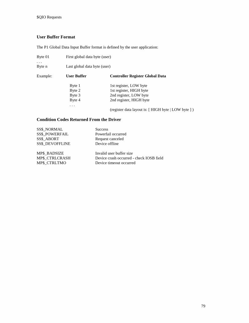
$QIO Requests
79
User Buffer Format
The P1 Global Data Input Buffer format is defined by the user application:
Byte 01 First global data byte (user). . .Byte n Last global data byte (user)
Example: User Buffer Controller Register Global Data
Byte 1 1st register, LOW byteByte 2 1st register, HIGH byteByte 3 2nd register, LOW byteByte 4 2nd register, HIGH byte. . .
(register data layout is: [ HIGH byte | LOW byte ] )
Condition Codes Returned From the Driver
SS$_NORMAL SuccessSS$_POWERFAIL Powerfail occurredSS$_ABORT Request canceledSS$_DEVOFFLINE Device offline
MP$_BADSIZE Invalid user buffer sizeMP$_CTRLCRASH Device crash occurred - check IOSB fieldMP$_CTRLTMO Device timeout occurred

$QIO Requests
80
6.11 IO$_GET_CS Get Configuration Status Information
This request retrieves the current configuration status from the peer processor of the specified device andplaces it in the user buffer. The optional function modifier IO$M_ERASE causes the device’scommunication error counters to be cleared after they are read.
The buffer format is shown in the description of ‘Get/Clear Network Statistics’ in Appendix B.
Restrictions
If the input buffer is not large enough to contain the input during processing a bad size error will bereturned (MP$_BADSIZE). The minimum buffer size is currently 55 words (110 bytes).
Function Modifiers
IO$M_ERASE Clear the device’s error counters after reading them.
Parameters
P1 The VAX starting address of the output buffer to receive the configuration status information.
P2 The size in bytes of the P1 buffer.
Device Commands Issued
Configuration Status
Valid IOSB Fields
Driver Condition CodeTransfer CountDevice Crash CodePath Number

$QIO Requests
81
User Buffer Format
The P1 Configuration Status Information Input Buffer format is shown in the description of ‘Get/ClearNetwork Statistics’ in Appendix B.
Condition Codes Returned From the Driver
SS$_NORMAL SuccessSS$_POWERFAIL Powerfail occurredSS$_ABORT Request canceledSS$_DEVOFFLINE Device offline
MP$_BADSIZE Invalid user buffer sizeMP$_CTRLCRASH Device crash occurred - check IOSB fieldMP$_CTRLTMO Device timeout occurredMP$_CTRLERR Device error occurred

$QIO Requests
82
6.12 IO$_GET_SR Get Service Request Information
This request retrieves the service request status information from the specified device and places it in theuser buffer.
Note that the device driver issues Get Service Request commands to the devices as part of its processing ofother user requests. Because of this, some of the Get Service Request Information received as a result ofthis $QIO/$QIOW could be invalid by the time it is received. Refer to the Device Commands Issued listingfor each request to determine which ones issue this command during processing.
Restrictions
If the input buffer is not large enough to contain the input during processing a bad size error will bereturned (MP$_BADSIZE). The minimum buffer size is currently 12 bytes.
Function Modifiers
None.
Parameters
P1 The starting address of the output buffer to receive the configuration status information.
P2 The size in bytes of the P1 buffer.
Device Commands Issued
Get Service Request
Valid IOSB Fields
Driver Condition CodeTransfer CountDevice Crash CodePath Number

$QIO Requests
83
User Buffer Format
Byte 01 Data Master path service request bit-map.Byte 02 Data Slave path service request bit-map.Byte 03 Program Master path service request bit-map.Byte 04 Program Slave path service request bit-map.Byte 05 Global data present bit-map, nodes 1-8.Byte 06 Global data present bit-map, nodes 9-16.Byte 07 Global data present bit-map, nodes 17-24.Byte 08 Global data present bit-map, nodes 25-32.Byte 09 Global data present bit-map, nodes 33-40.Byte 10 Global data present bit-map, nodes 41-48.Byte 11 Global data present bit-map, nodes 49-56.Byte 12 Global data present bit-map, nodes 57-64.
Condition Codes Returned From the Driver
SS$_NORMAL SuccessSS$_POWERFAIL Powerfail occurredSS$_ABORT Request canceledSS$_DEVOFFLINE Device offline
MP$_BADSIZE Invalid user buffer sizeMP$_CTRLCRASH Device crash occurred - check IOSB fieldMP$_CTRLTMO Device timeout occurred

$QIO Requests
84
6.13 IO$_GET_SS Get Driver Status / Statistics
This request retrieves the current driver status and statistics for the specified device and places it in the userbuffer. Most of the information returned by this request concerns driver internal functions which do notaffect the user application.
Restrictions
If the input buffer is not large enough to contain the input during processing, a bad size error will bereturned (MP$_BADSIZE). The minimum buffer size is 316 bytes.
Function Modifiers
None.
Parameters
P1 The VAX starting address of the input buffer to receive the status and statistics information.
P2 The size in bytes of the P1 buffer.
Device Commands Issued
None.
Valid IOSB Fields
Driver Condition CodeTransfer CountPath Number
Condition Codes Returned From the Driver
SS$_NORMAL SuccessSS$_POWERFAIL Powerfail occurredSS$_ABORT Request canceledSS$_DEVOFFLINE Device offline
MP$_BADSIZE Invalid user buffer size

$QIO Requests
85
User Buffer Format
Byte 001-003 Driver version.Byte 004 Modbus Plus node address.Byte 005 Device type.Byte 006 Device status.Byte 007 Device needs.Byte 008 Latest VAX-to-device command.Byte 009 Latest device-to-VAX response.Byte 010 Latest device crash code.Byte 011 Program master path connect status.Byte 012 - 015 Number of unit Control Blocks cloned.Byte 016 - 019 Number of paths allocated.Byte 020 - 023 Number of paths deallocated.Byte 024 - 027 Number of watchdog timer expirations.Byte 028 - 031 Number of device service entries.Byte 032 - 035 Number of device commands issued.Byte 036 - 039 Number of device soft resets.Byte 040 - 043 Number of device hard resets.Byte 044 - 047 Number of interrupts.Byte 048 - 051 Number of unsolicited interrupts.Byte 052 - 055 Number of weird interrupts.Byte 056 - 059 Number of device timeouts.Byte 060 - 063 Number of user timeouts.Byte 064 - 067 Number of device errors.Byte 068 - 071 Number of QIOs canceled.Byte 072 - 075 Number of cancels causing path deallocations.Byte 076 - 079 Number of abort request entries.Byte 080 - 083 Number of get service request entries.Byte 084 - 087 Number of start I/O entries.Byte 088 - 091 Number of I/O done entries.Byte 092 - 095 Number of get service request case #1 entries.Byte 096 - 099 Number of get service request case #2 entries.Byte 100 - 103 Number of get service request case #3 entries.Byte 104 - 107 Virtual address of CSR.Byte 108 - 111 Virtual address of shared RAM.Byte 112 - 303 Path table.Byte 304 - 315 Latest get service request bit-map.

$QIO Requests
86
6.14 IO$_ABORT Abort Transaction
This request issues an Abort Transaction command for the specified device and path, cleans up any in-progress transactions on this path, and forces the path state to Allocated.
Restrictions
A path must already be allocated to the current I/O channel or a path error will be returned(MP$_NOPATH).
Function Modifiers
None.
Parameters
None.
Device Commands Issued
Abort Transaction
Valid IOSB Fields
Driver Condition CodeTransfer CountPath Number
Condition Codes Returned From the Driver
SS$_NORMAL SuccessSS$_POWERFAIL Powerfail occurredSS$_ABORT Request canceledSS$_DEVOFFLINE Device offline
MP$_CTRLCRASH Device crash occurred - check IOSB fieldMP$_CTRLTMO Device timeout occurredMP$_NOPATH Path error occurred

Driver Utilities

Driver Utilities
88
7. Driver UtilitiesThe following utilities are provided with the SA85 OpenVMS/AXP device driver:
• Devdmp - Formats contents of driver tables. Used for reporting bugs and diagnosing driver faults.
• NDU - Network Diagnostic Utility. This utility was migrated from the existing Modbus driver forOpenVMS/VAX to the OpenVMS/AXP platform. Reference the Modicon: “DEC Host Based DevicesUser’s Guide” for a description of this utility.
• MBP_ERRFMT - This utility will format out the error log packets logged by the MPDRIVER.
The “MBPLUS_” logical name points to the product directory as created by the kit installation. It isassumed the MBP_STARTUP.COM command file contained within the product directory has beenexecuted to define this logical name. The file: MBPLUS_:MBP_SYMBOLS.COM will define the foreignsymbols for the SA85 device driver utilities.
7.1 DEVDMPDEVDMP is a DCL utility that takes a single parameter, the DEVICE name. The user must define theforeign command symbol as follows:
$DEVDMP == “$MBPLUS_:DEVDMP”
This utility does a change mode to Kernel and therefore must have this privilege granted in the user’sauthorization file. To evoke DEVDMP type the following:
$DEVDMP device nameExamples:
$DEVDMP JPA10:$DEVDMP JPA1:
The driver maintains two devices per controller, one for servicing the unsolicited interrupts from the SA85(device zero), and a template device that is copied whenever a user assigns a channel to the device (deviceone). DEVDMP first formats the UCB for the requested device, the controller dependent structure (CBF),and some fields of UCB zero.

Driver Utilities
89
7.2 MBP_ERRFMTMBP_ERRFMT is a DCL utility that formats VMS error log packets from the MPDRIVER. The user mustdefine the foreign command symbol as follows:
$MBP_ERRFMT == “$MBPLUS_:MBP_ERRFMT”
The syntax of the DCL command line to MBP_ERRFMT is as follows:
$MBP_ERRFMT [/err=filename][/out=filename][/start=vaxtime][/end=vaxtime]
err=VMS filename of the error log file. The default is SYS$ERRORLOG:ERRLOG.SYS. This switchallows the user to examine alternate error log files, or files that were extracted with"analyze/error_log/binary=filename".
out=VMS filename or device for formatted listing. Default is sys$output.
start=VMS timestamp to limit search for entries after the indicated time. Default is all entries that arewithin the last two days.
end=VMS timestamp to limit search for entries before the indicated time. Default is current time.
Example:
The following command would examine the current default error log file and format any foundMPDRIVER error log entries to the output file: MBP_ERRORS.LIS that have been logged today.
$MBP_ERRFMT/OUT=MPB_ERRORS.LIS/START=TODAY

Driver Utilities
90
7.3 DCL_READ_REGDCL_Read_Reg is a general purpose DCL foreign command. This utility will read up to forty holdingregisters (40001 to 49999) from any slave Modbus Plus node. This utility allocates a Modbus Plus Programmaster path to acquire the data. The utility will display data to the user and optionally place the data intoDCL symbols. DCL_Read_Reg can be set up as a foreign command as follows. The following line wasextracted from the MBP_STARTUP.COM command procedure which defines other foreign command.
$ rr :== "$dcl_readreg"
The DCL syntax for the utility is shown below. This utility also uses the process symbol table to save theroute and holding register last read or it may be set by the user prior to executing the command. The twosymbols used are: MBP_START_REGISTER and MBP_ROUTE.
$ rr /reg= Starting holding register- /route=(xx.xx.xx.xx.xx)- /count=<>- [/adapter=]- [/byte]- [/hex]- [/ASCII]- [/symbols]
/reg=Starting holding register. This may be omitted if the DCL symbol: MBP_START_REGISTERpopulated with a valid holding register.
/route=Route path to the PLC. This may be omitted if the DCL symbol: MBP_ROUTE populated with avalid route path.
/adapter=Modbus Plus adapter to use. By default, it uses JPA1:. The user enters: 0= jpa1:, 1= jpb1:, 2=jbc1: , or 3= jbd1:
/byte=Byte swap the data before displaying.
/hex=Display data in hex.
/ASCII=Display or store data in symbol as ASCII. First null in holding register read will terminate string.
/symbols=If present, then this utility will populate DCL symbols HR_1 to HR_nn where nn= count if"/ASCII" is not specified. Otherwise, HR_ASCII is set to the ASCII text.

VMSINSTALEXAMPLE

VMSINSTAL Example
92
8. VMS InstallationThe following is an example VMSINSTAL installation procedure. The user input is bolded.
$ set def sys$update$@vmsinstal
OpenVMS AXP Software Product Installation Procedure V6.2
It is 13-NOV-1996 at 09:01.
Enter a question mark (?) at any time for help.* Are you satisfied with the backup of your system disk [YES]? y* Where will the distribution volumes be mounted: sys$update:
Enter the products to be processed from the first distribution volumeset.* Products: mbp019* Enter installation options you wish to use (none):
The following products will be processed:
MBP V1.9
Beginning installation of MBP V1.9 at 09:02
%VMSINSTAL-I-RESTORE, Restoring product save set A ...
MODBUS Plus SA85 Device Driver13-Nov-1996
Copyright by:IPACT Inc.260 S. CampbellValparaiso, IN 46383Ph: 219-464-7212
All rights reserved
The distribution files have been restored from thesaveset. The installation procedure is continuing...Your system or common device/directory: IPCNET$DKA300:[SYS0.SYSCOMMON.]This product by default creates the directory:
IPCNET$DKA300:[SYS0.SYSCOMMON.][MBP019]
* Use default directory location [Y]? y
The following two questions can be acquired byusing sysman and finding the EISA adapter number and theCSR for the EISA adapter. For the EISA CSR, enter onlythe last eight digits (e.g. do not enter the leadingeight FFFFFFFFs).
Only the serial number from the first SA85-002is required along with the IPACT license number. Theserial number from the card along with the license number areused to validate a proper license of this software product.Contact IPACT Inc. at 219-464-7212 if you donot have a licensepack.

VMSINSTAL Example
93
* Enter Serial number of the first SA85-002 [0]: ####
* Enter license number for SA85 Serial number: 10: ####
Validating license for SA85 Serial number: ####License number: ####
The following question determines how the IRQ and vectorare mapped for your system. Depending on the model, theIRQs from the SA85 may be mapped differently. Currently,only the Sable (ALPHA 2100) should be answered with a "2".All other CPUs should be answered with the default of "1".
If the wrong option is selected, the SA85 will failto interrupt to the correct vector used by the device driver.
* Enter CPU type [ 1 or 2] [1]:
The EISA adapter or the ISA adapter and the CSR can befound by using "MCR SYSMAN IO SHOW BUS". For some CPU's,it is listed as the XBUS.
* Enter EISA adapter number [2]:
* Enter EISA adapter CSR address (in hex) [8644C000]:
* How many SA85 ISA Modbus Plus devices [1]:
* Enter IRQ for SA85 number 1: [4]:
* Enter ISA slot for SA85 number 1: [4]:
* Enter base address for SA85 number: 1 (in hex): [000C0000]:
CPU Type: 1Adapter Number: 2Adapter CSR: FFFFFFFF8644C000SA85 1 IRQ: 4, Slot: 4, Base: 000C0000Target Product location: SYS$COMMON:[MBP019]
* Are these correct [Y]? y
MBP_I_COFFEEBREAK answer section complete
MBP_I_COMMAND Building startup command file MBP_STARTUP.COMMBP_I_DIRECTORY Creating SYS$COMMON:[MBP019]%VMSINSTAL-I-SYSDIR, This product creates system disk directory
SYS$COMMON:[MBP019].%VMSINSTAL-I-SYSDIR, This product creates system disk directory
SYS$COMMON:[MBP019.EXAMPLES].MBP_I_MOVING Marking files to moveMBP_I_COMPLETE KITINSTAL.COM complete
This kit currently is not supplied with anIVP. The command file: MBP_STARTUP.COM has beenplaced in the product directory. Do not run thisfile until you are sure that the SA85s have been configuredas you specified earlier, and the ECU has also beenrun to configure the IRQs, and the memory mapped by theSA85s.
Your installation is now complete.%VMSINSTAL-I-MOVEFILES, Files will now be moved to their targetdirectories...
Installation of MBP V1.9 completed at 09:06

VMSINSTAL Example
94
Adding history entry in VMI$ROOT:[SYSUPD]VMSINSTAL.HISTORY
Creating installation data file: VMI$ROOT:[SYSUPD]MBP019.VMI_DATA
Enter the products to be processed from the next distribution volumeset.* Products:
VMSINSTAL procedure done at 09:06
8.1 Additional Release Notes
It was found that the equivalence of some of the I/O function codes used by the driver were changed in thecurrent release of OpenVMS. The prior SQ85 device driver QIO function codes were defined using aninclude file that did not use the definitions defined by the OpenVMS supplied standard definitions. Theheader file supplied with this SA85 device driver uses the OpenVMS supplied header definition file:IODEF.H to define the SA85 device driver’s I/O function codes. Any previous users who had beenincluding “v_mpfunc.h” should include from the MBP.TLB text library: “mp_funcs.h” for “C” users or“mp_funcs.txt” for FORTRAN users.
The following files are written to the SYS$COMMON:[MBP019] on the user’s system disk.
Directory SYS$COMMON:[MBP019]
DEVDMP.EXE - Developer’s driver database display utilityMBP.OLB - Object library containing message definition file for the MPDRIVER.MBP_C.TLB - C header definitions text libraryMBP_ERRFMT.EXE - Formats MPDRIVER error log entriesMBP_FOR.TLB - FORTRAN include filesMBP_STARTUP.COM - Loads device driverNDU.EXE - Network Diagnostic UtilitySYS$MPDRIVER.EXE - SA85 driverSYS$MPDRIVER.STB - SA85 driver symbol table

VMSINSTAL Example
95
To install the driver, the user needs to execute the following command file:
$@SYS$COMMON:[MBP019]MBP_STARTUP.COM.
The Modicon Modcom III Communications Software Library has not been tested with the device driver asit is not available on the OpenVMS/AXP platform at this time. The IPACT Communications Library wastested and functions with the device driver and if licensed is installed as part of the VMSINSTAL kit.
8.2 Test EnvironmentThis release of the Modbus Plus Device driver for OpenVMS/AXP with the ISA SA85 has been tested on asingle processor Alpha with an EISA bus (Alpha DEC 2000 model 150). Due to hardware availability, onlya single SA85 was tested, however, the driver was designed to support up to four SA85s installed in theEISA bus. The OpenVMS/AXP device driver MPDRIVER is a STEP 2 device driver and is thereforeavailable on OpenVMS/AXP version 6.1 or later. The AM-SA85-002 SA85 was the only device tested andfound to function correctly. An AM-SA85-000 was also tested, but failed to interrupt. The AT-984 wastested, but it also failed to interrupt. Further discussion with Modicon resolved that these other devices donot have interrupt capabilities.

96
Modbus Commands for Modbus Plus

Modbus Commands for Modbus Plus
97
9. Modbus Commands for Modbus Plus� Modbus Protocol for Modbus Plus � The Modbus Transaction � Modbus Command Summary � Read Coil Status (Function 01) � Read Input Status (Function 02) � Read Holding Registers (Function 03) � Read Input Registers (Function 04) � Force Single Coil (Function 05) � Preset Single Register (Function 06) � Read Exception Status (Function 07) � Get/Clear Network Statistics (Function 08, Subfunction 21) � Force Multiple Coils (Function 0F) � Preset Multiple Registers (Function 10 Hex) � Report Slave ID (Function 11 Hex) � Exception Responses
Modbus Commands for Modbus Plus
98
9.1.1 Modbus Protocol for Modbus Plus
This appendix describes Modbus commands as they are used in Modbus Plus. This information is intendedfor programmers who wish to write applications that communicate between the host based devices andModicon 984 controllers.
Modicon 984 controllers use the Modbus protocol to access data and statistics. Modbus Plus uses a set ofModbus commands to perform data acquisition tasks between your host based device and Modicon 984controllers across the network.
The Modbus protocol determines how:
� The message sender and receiver identify each other � The system maintains network-wide order as messages are exchanged � Errors on the network are detected
9.1.2 The Master-Slave Relationship on Modbus and Modbus Plus
In the original Modbus protocol, only one master device can exist on a single network, originating contactswith multiple slave devices. The Modbus Plus peer-to-peer protocol allows multiple masters to contactmultiple slave devices. Concurrent transactions are handled using multiple paths of various types in thedevices.
The Modbus protocol uses a query-response cycle between master and slave devices. A complete messagetransaction consists of a query originated by a Modbus master device and a response sent by the slave backto the master.
9.1.3 Creating Modbus Queries and Responses
A Modbus query message originated by a host application can be constructed in a data buffer. The messageshould consist of the Modbus function code and data elements in the formats described in this appendix. Tosend the message, the buffer can be accessed by the $QIO/$QIOW functions for Modbus Plus.
Similarly, a slave application in the host can receive the query into a buffer using $QIO/$QIOW functions.It can construct the response message in a buffer and send it.
The processes of obtaining a network path, designating a Modbus Plus destination node, and imbedding theModbus message into a Modbus Plus message packet are handled by the $QIO/$QIOW functions andnetwork hardware.

Modbus Commands for Modbus Plus
99
Eight-BitData Bytes
9.2 The Modbus Transaction
The format for Modbus commands or responses is an eight-bit function code followed by a block of eight-bit bytes (maximum length: 252 bytes).
Master and Slave Query-Response Cycle
The Query: The function code in the query tells the addressed slave device what kind of action to perform.The data bytes contain any additional information that the slave will need to perform the function. Forexample, if you issue function code 03, querying the slave to read holding registers and respond with theircontents, the data field must contain information telling the slave which register to start at and how manyregisters to read.
The Response: If the slave makes a normal response, the function code in response is an echo of thefunction code in the query. The data bytes contain the data collected by the slave, such as register values orstatus. If an error occurs the function code is modified to indicate that the response is an error response,and the data bytes contain a code that describes the error.
Query from MasterFunction Code
Eight-BitData Bytes
Function Code
Response from Slave

Modbus Commands for Modbus Plus
100
The buffer contents of the message as it is used for Modbus Plus are nearly the same as in a standardModbus message, with two exceptions:
A Modbus message contains the slave device address. This is stripped from the Modbus messagecontents before transmission over Modbus Plus. It appears instead in the Modbus Plus MAC leveldestination field.
The Modbus CRC/LRC error check field is stripped from the message contents. Error checking is
performed on the entire Modbus Plus message in the HDLC level CRC-16 field.
Code (In Hex) Meaning Action
01 Read Coil Status Obtain the current ON/OFF status of a group oflogic coils
02 Read Input Status Obtain the current ON/OFF status of a group ofdiscrete inputs
03 Read Holding Registers Obtain the current binary value in one or moreholding registers
04 Read Input Registers Obtain the current binary value in one or moreinput registers
05 Force Single Coil Force a logic coil ON or OFF
06 Preset Single Register Place a specific binary value in a holding register
07 Read Exception Status Obtain the current ON/OFF status of internal coils00001 ... 00008 in a 984 controller; user logicdetermines the status of the coils; short messagelength allows rapid reading
08 (sub 15 hex) Get/Clear Network Statistics Obtain current network statistics from the host;specify subfunction 21 (15 hex)
09 ... 0E Reserved
0F Force Multiple Coils Force a set of consecutive coils ON or OFF
10 Preset Multiple Registers Place a specific binary values into a series ofconsecutive holding registers
17 Report Slave ID Lets the master decide the slave type and status ofthe slave’s RUN light
18 ... FF Reserved

Modbus Commands for Modbus Plus
101
9.3 Specifying Discrete and Register References
In the Modbus message the type of reference to be accessed (e.g., discrete coil, discrete input, input register,or holding register) is specified in the function code. All discrete or register addresses within the Modbusdata portion of the message are in hexadecimal and are numbered relative to a base reference of zero. Theaddress is specified as an offset from the base reference (0000) of that type.
For example, the first holding register in the 984 controller is termed 40001, and is addressed in a ReadHolding Registers command as register address 0000. Similarly, the first coil is termed 00001 and isaddressed in a Read Coil Status command as 0000. Coil 00127 is addressed as 007E hexadecimal (126decimal).
Note All numbers in Modbus are in hexadecimal and are referred to in high byte and low byteformat. In the above example, coil 00127 (007E hex) is represented with a high byte of 00and a low byte of 7E.
9.4 Read Coil Status (Function 01)
Read Coil Status reads the power bit of 0xxxx coils and packs them together eight per byte, starting at theleast significant bit of the first byte. Any unused bits in the last byte are padded with zeros at the highorder end of the byte. The maximum number of coils that can be read is 2000, returned in up to 250 bytes.
Normal Cycle for Modbus Function 01
Note All 0xxxx coils specified in the query must exist in the 984 for this command to beprocessed. If not, the slave device will return an exception response.
First Coil Read(High Byte)
First Coil Read(Low Read)
# of Coils Read(High Byte
# of Coils Read(Low Byte)
Query from MasterFunction Code 01
Response from Slave
# of Data BytesRead
First Eight Coils(Byte 1)
Second Eight Coils(Byte 2)
.
.
.
Function Code 01

Modbus Commands for Modbus Plus
102
9.5 Read Input Status (Function 02)
Read Input Status reads the power bit of 1xxxx discrete inputs and packs them together eight per byte,starting at the least significant bit of the first byte. Any unused bits in the last byte are padded with zeros atthe high order end of the byte. The maximum number of discrete inputs that can be read is 2000, returnedin up to 250 bytes.
Normal Cycle for Modbus Function 02
Note All 1xxxx inputs specified in the query must exist in the 984 for this command to beprocessed. If not, the slave device will return an exception response.
Query from Master
First 1xxxx Read(High Byte)
First 1 xxxx Read(Low Byte)
# of Inputs Read(High Byte
# of Inputs Read(Low Byte)
Function Code 02
# of Data BytesRead
First Eight Inputs(Byte 1)
Second Eight Inputs(Byte 2)
.
.
.
Function Code 02
Response from Slave

Modbus Commands for Modbus Plus
103
9.6 Read Holding Registers (Function 03)
Read Holding Registers reads the contents of 4xxxx output registers and returns them two bytes per register.The maximum number of 4xxxx registers that can be read in one function 03 operation is 125, returned in upto 250 bytes.
Normal Cycle for Modbus Function 03
Note All 4xxxx registers specified in the query must exist in the 984 for this command to beprocessed. If not, the slave device will return an exception response.
First 4 xxxx Read(High Byte)
First 4 xxxx Read(Low Byte)
Set to 00
# Registers to Read(Range: 01 ... FA)
Query from MasterFunction Code 03
Response from Slave
# of Data BytesRead
First Register(High Byte)
First Register(Low Byte)
Second Register(High Byte)
.
.
.
Function Code 03

Modbus Commands for Modbus Plus
104
9.7 Read Input Registers (Function 04)
Read Input Registers reads the contents of 3xxxx input registers and returns them two bytes per register.The maximum number of 3xxxx registers that can be read in one function 04 operation is 125 returned in upto 250 bytes.
Normal Cycle for Modbus Function 04
Note All 3xxxx registers specified in the query must exist in the 984 for this command to beprocessed. If not, the slave device will return an exception response.
First 3 xxxx Read(High Byte)
First 3 xxxx Read(Low Byte)
Set to 00
# Registers to Read(Range: 01 ... FA)
Query from MasterFunction Code 04
Response from Slave
# of Data BytesRead
First Register(High Byte)
First Register(Low Byte)
Second Register(High Byte)
.
.
.
Function Code 04

Modbus Commands for Modbus Plus
105
9.8 Force Single Coil (Function 05)
A Force Single Coil command sets or clears the current power state of a coil. The history bit associatedwith the coil is also updated so that transitionals will work correctly. The function uses four bytes for thequery and four bytes for the response; the byte implementation is identical in both the query and response.
The first two bytes give you 17 bits with which to specify in binary notation the number of the coil to beforced. To force the coil ON, set all eight bits in the third byte to 1; to force the coil OFF, clear all eightbits in the third byte to 0. The fourth byte must be present, and its eight bits must always be cleared to 0.
Normal Cycle for Modbus Function 05
Note Remember when you specify a coil number in bytes 1 and 2 that the binary representation ofcoil 0 corresponds to reference 00001.
Caution Function 05 will override both the controller’s MEMORY PROTECT and the coilDISABLE state.
Binary Coil Number(High Byte)
Binary Coil Number(Low Byte)
FF = Coil SET 00 = Coil CLEAR
Set to 00
Query from MasterFunction Code 05
Response from Slave
Binary Coil Number(High Byte)
Binary Coil Number(Low Byte)
FF = Coil SET 00 = Coil CLEAR
Set to 00
Function Code 05

Modbus Commands for Modbus Plus
106
9.9 Preset Single Register (Function 06)
A Force Single Register command sets the contents of a 4xxxx register. The function uses four bytes forthe query and four bytes for the response; the byte implementation is identical in both the query andresponse.
The first two bytes give you 17 bits with which to specify in binary notation the number of the register to beset. The last two bytes give you 16 bits with which to specify the new register content.
Normal Cycle for Modbus Function 06
Note Remember when you specify the register number in bytes 1 and 2 that the binaryrepresentation of register 0 corresponds to reference 40001.
Caution Function 06 will override the controller’s MEMORY PROTECT.
Binary Reg. Number(High Byte)
Binary Reg. Number(Low Byte)
New Register Data(High Byte)
New Reigster Data(Low Byte)
Query from MasterFunction Code 06
Response from Slave
Binary Reg. Number(High Byte)
Binary Reg. Number(Low Byte)
New Register Data(High Byte)
New Register Data(Low Byte)
Function Code 6

Modbus Commands for Modbus Plus
107
9.10 Read Exception Status
(Function 07)
A Read Exception Status function requests the current power state of the first eight coils in the 984controller. The state of these coils is returned in a single data byte in the response - the power state of thefirst coil is returned in the least significant bit of the data type.
Normal Cycle for Modbus Function 07
Query from MasterFunction Code 07
Response from Slave
Coil Status Data
Function Code 07

Modbus Commands for Modbus Plus
108
9.11 Get/Clear Network Statistics
(Function 08, Subfunction 21)
In order to obtain network statistics from a host device, function 8 must be used in conjunction withsubfunction code 21 (hex 15), which is specified in the first two bytes following the function code in thequery. To Get Statistics, specify 03 in the fourth byte following the function code; to Clear Statistics,specify 04 in that byte.
Normal Cycle for Modbus Function 08, Subfunction 21
Note Other diagnostic subfunctions accessible through Modbus function 08 are not applicable toModbus Plus networks.
The Modbus Plus network statistics accessible via this function are described on the next four pages.
Set to 00
Set to 15 hex
Set to 00
03 = Get Statistics 04 = Clear Statistics
Query from MasterFunction Code 08
Response from Slave
0
15 hex
0
3 or 4
Length: 108
Statistics: Byte 0
Statistics: Byte 1...
Statistics: Byte 108
Function Code 05

Modbus Commands for Modbus Plus
109
Modbus Plus Network Statistics
10,9 Peer status (LED code); provides status of this unit relative to the network:
0 Monitor link operation32 Normal link operation64 Never getting token96 Sole station128 Duplicate station
_____________________________________________________________________________________Note: The notation (1,0) means that the data is formed with byte 1 as the most significant
byte, and with byte 0 as the least significant byte.
Bytes Meaning
2,1 Node type ID:(see note below) 0 Unknown node type
1 Programmable controller node2 Modbus bridge node3 Host computer node4 Bridge Plus node5 Peer I/O node
4,3 Most significant bit in byte 3 defines use of error counters in bytes, 30, 31Least significant half of byte 3, plus byte 2, contain software version.
Layout: Byte 3 Byte 2
6,5 Network address for this station
8,7 MAC state variable:0 Power up state1 Monitor offline state2 Duplicate offline state3 Idle state4 Use token state5 Work response state6 Pass token state7 Solicit response state8 Check pass state9 Claim token state10 Claim response state
[ ] [---Software version in hex----]
\Most significant bit defines error counters
(see bytes 30, 31)

Modbus Commands for Modbus Plus
110
12.11 Token pass counter; increments each time this station gets the token
14,13 Token rotation time in ms
15 Data master failed during token ownership bit map16 Program master failed during token ownership bit map
17 Data master token owner work bit map18 Program master token owner work bit map
19 Data slave token owner work bit map20 Program slave token owner work bit map
21 Data master/get master response transfer request bit map22 Data slave/get slave command transfer request bit map
23 Program master/get master response transfer request bit map24 Program slave/get slave command transfer request bit map
25 Program master connect status bit map26 Program slave automatic logout request bit map
27 Pre-transmit deferral error counter28 Receive buffer DMA overrun error counter
29 Repeated command received counter30 Frame size error counter
If the MSB in byte 4 is not set, bytes 31 and 32 have the following meaning:
31 Receiver collision-abort error counter32 Receiver alignment error counter
If the MSB in byte 4 is set, bytes 31 and 32 have the following meaning:
31 Cable A framing error counter32 Cable B framing error counter
33 Receiver CRC error counter34 Bad packet-length error counter
35 Bad link-address error counter36 Transmit buffer DMA-underrun error counter
37 Bad internal packet length error counter38 Bad MAC function code error counter
39 Communication retry counter40 Communication failed error counter
41 Good receive packet success counter42 No response received error counter
43 Exception response received error counter

Modbus Commands for Modbus Plus
111
44 Unexpected path error counter
45 Unexpected response error counter46 Forgotten transaction error counter
47 Active station table bit map, nodes 1...848 Active station table bit map, nodes 9...16
49 Active station table bit map, nodes 17...2450 Active station table bit map, nodes 25...32
51 Active station table bit map, nodes 33...4052 Active station table bit map, nodes 41...48
53 Active station table bit map, nodes 49...5654 Active station table bit map, nodes 57...64
55 Token station table bit map, nodes 1...856 Token station table bit map, nodes 9...16
57 Token station table bit map, nodes 17...2458 Token station table bit map, nodes 25...32
59 Token station table bit map, nodes 33...4060 Token station table bit map, nodes 41...48
61 Token station table bit map, nodes 49...5662 Token station table bit map, nodes 57...64
63 Global data present table bit map, nodes 1...864 Global data present table bit map, nodes 9...16
65 Global data present table bit map, nodes 17...2466 Global data present table bit map, nodes 25...32
67 Global data present table bit map, nodes 33...4068 Global data present table bit map, nodes 41...48
69 Global data present table bit map, nodes 49...5670 Global data present table bit map, nodes 57...64
71 Receive buffer in use bit map, buffer 1...872 Receive buffer in use bit map, buffer 9...16
73 Receive buffer in use bit map, buffer 17...2474 Receive buffer in use bit map, buffer 25...32
75 Receive buffer in use bit map, buffer 33...4076 Station management command processed initiation counter
77 Data master output path 1 command initiation counter78 Data master output path 2 command initiation counter
79 Data master output path 3 command initiation counter80 Data master output path 4 command initiation counter

Modbus Commands for Modbus Plus
112
81 Data master output path 5 command initiation counter82 Data master output path 6 command initiation counter
83 Data master output path 7 command initiation counter84 Data master output path 8 command initiation counter
85 Data slave input path 41 command processed counter86 Data slave input path 42 command processed counter
87 Data slave input path 43 command processed counter88 Data slave input path 44 command processed counter
89 Data slave input path 45 command processed counter90 Data slave input path 46 command processed counter
91 Data slave input path 47 command processed counter92 Data slave input path 48 command processed counter
93 Program master output path 81 command initiation counter94 Program master output path 82 command initiation counter
95 Program master output path 83 command initiation counter96 Program master output path 84 command initiation counter
97 Program master command initiation counter98 Program master output path 86 command initiation counter
99 Program master output path 87 command initiation counter100 Program master output path 88 command initiation counter
101 Program slave input path C1 command processed counter102 Program slave input path C2 command processed counter
103 Program slave input path C3 command processed counter104 Program slave input path C4 command processed counter
105 Program slave input path C5 command processed counter106 Program slave input path C6 command processed counter
107 Program slave input path C7 command processed counter108 Program slave input path C8 command processed counter

Modbus Commands for Modbus Plus
113
9.12 Force Multiple Coils
(Function 0F)
A Force Multiple Coils function sets or clears the current power state of a set of up to 800 consecutivecoils. The history bits associated with the coils are also updated so that transitionals will work correctly.
Normal Cycle for Modbus Function 0F
The number of bytes in the query data buffer is the integer part of (# of coils Forced + 7) divided by 8. Abyte in this data buffer stores the state of eight consecutive coils - to force a coil ON, set its representativebit to 1; to force the coil OFF, clear the associated bit to 0.
NOTE Remember when you specify coils in the data bytes that the binary representation is 1less than the coil reference number - e.g., coil 0 corresponds to reference 00001.
Caution Function 0F will override both the controller’s MEMORY PROTECT and thecoil DISABLE state.
First Coil Number(High Byte)
First Coil Number(Low Byte)
# of Coils Forced(High Byte)
# of Coils Forced(Low Byte)
# of Bytes in the QueryData Buffer
Query Data Buffer(First Byte)
.
.
.
Query from MasterFunction Code 0F
Response from Slave
First Coil Number(High Byte)
First Coil Number(Low Byte)
# of Coils Forced(High Byte)
# of Coils Forced(Low Byte)
Function Code 0F

Modbus Commands for Modbus Plus
114
9.13 Preset Multiple Registers
(Function 10 Hex)
A Preset Multiple Registers function sets the contents of a set of up to 100 consecutive 4xxxx registers, twobytes per register.
Normal Cycle for Modbus Function 10
The number of bytes in the query data buffer is the number of 4xxxx registers to be preset x2. The contentsof each register are preset with the high and low bits in two consecutive bytes per register.
Note Remember when you specify register content in the data bytes that the binaryrepresentation is 1 less than the coil reference number - e.g., register 0 corresponds toreference 40001.
Caution Function 10 hex will override the controller’s MEMORY PROTECT.
First Reg Number(High Byte)
First Reg Number(Low Byte)
# of Registers Set(High Byte)
# of Regsters Set(Low Byte)
# of Bytes in the QueryData Buffer
Query Data Buffer(First Byte)
.
.
.
Query from MasterFunction Code 10
Response from Slave
First Reg Number(High Byte)
First Reg Number(Low Byte)
# of Registers Set(High Byte)
# of Registers Set(Low Byte)
Function Code 10

Modbus Commands for Modbus Plus
115
9.14 Report Slave ID
(Function 11 Hex)
Issuing a Report Slave ID function lets you obtain in a single response the slave type, its RUN light state,and- for a 984 controller - configuration information, machine status, and any potential stopped error code.
Normal Cycle for Modbus Function 11
The number of bytes in the query data buffer is the number of 4xxxx registers to be preset x 2. The contentsof each register are preset with the high and low bits in two consecutive bytes per register.
Byte Count = 09
Slave ID = 3
Slave RUN LED1 = ON, 0 = OFF
Page 0 Config Data(# of 4K Sections)
# of Segments
Controller Status(High Byte)
Controller Status(Low Byte)
Stopped Error Code(High Byte)
Stopped Error Code(Low Byte)
Query from Master
Function Code 11 Function Code 11

Modbus Commands for Modbus Plus
116
Reading the Controller Status
Word 101 in the 984 configuration table (in page 0 of system memory) indicates certain states of thecontroller. A state may be valid for the life of the controller (for example, the size of the configuration), ormay be set conditionally be external events (for example, MEMORY PROTECT currently ON or OFF).
Figure 7 - Machine State Bit Values
Information about 984 controller stopped error codes can also be obtained with this command. The codesare described on the next page.
16151413121110987654321
Not Used
Memory Config Flag
0 = Battery OK1 = Battery not OK
Enable Constant Sweep
0 = No Single Sweep1 = Enable Single Sweep
0 = No Single Sweep1 = Enable Single Sweep
0 = Should Never Be Displayed1 = Power OK ON
0 = RUN LED ON1 = RUN LED OFF
0 = MEMORY PROTECT ON1 = MEMORY PROTECT OFF
Not Used

Modbus Commands for Modbus Plus
117
Function 11 Hex (Continued)
Reading Stopped Error Codes
Stopped error codes for any 984 programmable controller on a Modbus Plus network can be accessed viafunction 11 hex. The current stopped state condition, if one exists, is stored in word 105 in the 984configuration table (in page 0 of system memory):
Figure 8 - Stopped Error Bit Values
16151413121110987654321
RTCFAILED
RIOFAILED
NODETYPE
DSCRDISAB
BADCONFIG
ULCSUMERR
For 984A/B/X Controllers: CPI Diagnostic FailureFor Other Controllers: BADOXUSED
NOEOLDOIO
PDCHEKSUM
SONNOTIST
BADSEGSCH
PORTIVENT
DIMAWAR
BADTCOP
PCSTOPPPCSICK

Modbus Commands for Modbus Plus
118
Legend Meaning
PCSICK Controller unhealthyPCSTOPPED Controller stoppedBADTCOP Bad I/O traffic cop tableDIMAWAR Controller in DIM AWARENESS statePORTIVENT Bad port interventionBADSEGSCH Bad segment scheduleSONNOTIST Start of network (SON) did not start segmentPDCHEKSUM Bad power - down checksumNOEOLDOIO Watchdog timer has expiredRTCFAILED Real time clock failureBADOXUSED Bad coil used tableRIOFAILED Remote I/O failureNODETYPE Illegal node type usedULCSUMERR User logic checksum errorDSCRDISAB Discrete disable errorBADCONFIG Bad configuration table

Modbus Commands for Modbus Plus
119
9.15 Exception Responses
When a programming or operation error occurs while issuing any of these Modbus data access commands,the slave responds to the master with an error message in the form of an exception code. Typical errors thatelicit exception responses include illegal data in a message, a controller’s failure to respond to an interfacepanel, or a difficulty communicating with a slave.
Four exception responses are possible in a Modbus Plus data acquisition operation:
Exception Code Error Condition
01 Illegal function for the addressed slave
02 Illegal data address within the information field for the addresses slave
03 Illegal data value in the information field for the addressed slave
06 Busy - the function just requested cannot be performed at this time because a long-durationPROGRAM command is being processed; reissue the command later
Exception codes 04, 05, and 07 are not applicable in Modbus Plus applications, and exception codes08...FF are reserved.
When a slave detects an error, it sends a response message to the master consisting of a function code andone of the above exception codes. The function code associated with an exception response is the originalfunction code + 80 hex - i.e., the high order bit in the function code of the original query is set to 1.

Modbus Commands for Modbus Plus
120
An Example
Here is an example of an incorrect query and the subsequent exception response:
Figure 9 - Incorrect Query - Example
The query above is a Read Coil Status, requesting the status of coil 1245 decimal. If the controller is a 1 Kmachine, this is an invalid reference. Consequently, the following exception response is generated:
Figure 10 - Exception Response - Example
The function code is the original query code + 80 (with its high order bit set to 1). Exception code 02indicates an illegal data address.
Responding as a Slave
A Modbus Plus application that handles Modbus protocol must function as a slave. Other devices on thenetwork will function as masters, sending queries to the application. The application can determine how torespond to those queries.
The application should issue an exception response for all Modbus function codes that it does notrecognize. Otherwise, the application should create the correct response message for the selected Modbusfunction code.
Function Start Address(High Byte)
Start Address(Low Byte)
# of Coils(High Byte)
# of Coils(Low Byte)
0100A10401
FunctionCode
ExceptionCode
0281

Crash Codes

Crash Codes
122
10. Crash Codes10.1 SA85 Controller Crash CodesThe following lists the SA85 peer processor crash codes. When the controller crashes, this information iscaptured by the device driver and stored with the error log.
A non-zero crash code that has bit seven clear, indicates that the interface died when an invalid interfacecommand was given to it by the driver or the Modbus Plus device driver failed to do a configuration statuscommand within the one second time-out. The Modbus Plus device driver will return status to all QIOs thatwere currently active, generate an error log packet, and reset the SA85.
A non-zero crash code that has bit seven set, indicates that the SA85 peer processor detected some sort ofinternal hardware or software error. A reset of the ALPHA EISA or ISA bus is required to clear this fault.This is accomplished with a power cycle or by pushing the “init” button on most ALPHAs.
HexCrashCode
Description
0 Interface operational1 2.0 Second interface time-out2 Bad interface opcode3 Interface data error4 Interface test error5 Interface transfer done error6 Bad interface path7 Path in wrong state8 Bad transfer length9 Global data length errorA Global data address errorB Global data not present81 Prom checksum error82 Internal RAM data test error83 External RAM data test error84 External RAM address test error85 Bad confidence test86 External int0 event error87 External int1 event error88 DMA int0 event error89 Comm. int event error
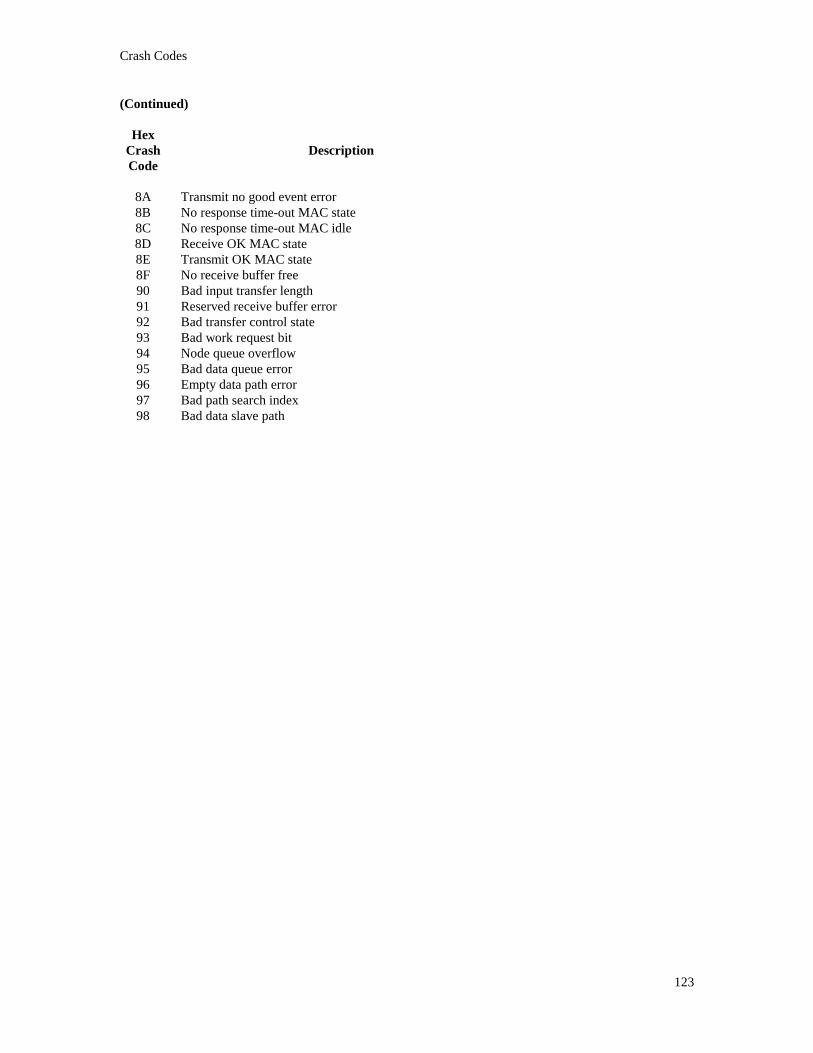
Crash Codes
123
(Continued)
HexCrashCode
Description
8A Transmit no good event error8B No response time-out MAC state8C No response time-out MAC idle8D Receive OK MAC state8E Transmit OK MAC state8F No receive buffer free90 Bad input transfer length91 Reserved receive buffer error92 Bad transfer control state93 Bad work request bit94 Node queue overflow95 Bad data queue error96 Empty data path error97 Bad path search index98 Bad data slave path

Driver Crash and Errorlog Codes

Driver Crash and Errorlog Codes
125
11. Driver Crash and Errorlog CodesThe following are crash codes that are generated by the driver and are not as a result of the SA85. Theywill show up only in the system error log file. The driver will recover from the error but it indicates that thedriver found an abnormal condition. These errors should be directed to IPACT.
HexCrashCode
Description
C0 This is a driver debug check. The driver logs this error log buffer when the driver was about to do anoutput but was interrupted by a GSR request from the SA85. The interrupted function is then called backto complete its processing.
C1 This is a driver debug check. The driver logs this when a master write is requested, but the path is in thewrong state. This can occur after a path abort or controller reset.
C2 This is a driver debug check. The driver logs this when a read master response is requested, but the pathis in the wrong state. This can occur after a path abort or controller reset.
C3 This is a driver debug check. The driver logs this when a read slave response is requested, but the path isin the wrong state. This can occur after a path abort or controller reset.
C4 This is a driver debug check. The driver logs this when a write slave response is requested, but the pathis in the wrong state. This can occur after a path abort or controller reset.
D1 While attempting process a get slave message, the driver path number was invalid for the slave path.This can occur after a path abort or SA85 reset. Otherwise, this is a driver fault. Examine the driverstack to find out what was the slave path that was completing. This test was done after the driver hadactually got the slave message response.
D2 The SA85 did not respond with the two's complement of the command that was sent to it. This wasdetected by the controller servicing code.
D3 While attempting to process a master response, the driver path number was invalid for the master path.This can occur after a path abort or SA85 reset. Otherwise, this is a driver fault. Examine the driverstack to find out what was the slave path that was completing.
D4 While attempting process a get slave message, the driver path number was invalid for the slave path.This can occur after a path abort or SA85 reset. Otherwise, this is a driver fault. Examine the driverstack to find out what was the slave path that was completing. This test is done when the driver haswritten a slave response such as a routing error to the Modbus master.
D5 A GSR indicated that we needed to read a slave message in. The controller service found the slave pathto be invalid.
D6 A GSR indicated that we needed to read a master response message in. The controller service found themaster path to be invalid.
D7 The driver was doing a controller function but the SA85 timed out.

Driver Crash and Errorlog Codes
126
(Continued)
HexCrashCode
Description
F9 A master output has timed out.
FA A master output has timed out.
FC A non-GSR response came in from the SA85, but there was no fork or I/O waiting for the response for auser UCB (not UCB zero).
FD A non-GSR response came in from the SA85, but there was no fork or I/O waiting for the response onUCB zero.
FE A master miscellaneous output has timed out.

Modbus Plus Driver Messages

Modbus Plus Driver Messages
128
12. Modbus Plus Driver MessagesThe following lists the VMS error codes returned in the I/O status block of the user’s QIO request. TheModbus Plus driver follows normal VMS standards for error codes where an odd status is successful.
MBP$_BADSIZE Invalid buffer sizeThe user passed a buffer that was too small for at least the size of the Modbus header or the sizerequired for the requested function.
MBP$_NOPATH User has requested a function that requires an allocated pathThe user has requested a function that requires the user allocate a master data path, slave data path,or a master program path. Call the driver with an allocate function first.
MBP$_BADPATH Invalid path numberThe user specified path number in the QIO argument is larger than the number available on theSA85 controller for that type of path.
MBP$_CTRLCRASH Modbus Plus controller crashedThe Modbus Plus SA85 controller has crashed. There should be an error log entry in the systemerror log file. Use MBP_ERRFMT to extract the error log entry. The driver attempts to protectthe SA85 from crashes, but program paths are allowed to perform any function. Consult the crashcodes in the appendix and contact IPACT if the problem can not be resolved.
MBP$_CTRLTMO Modbus Plus controller timed outA function to the controller did not complete within the default two seconds or the user specifiedtime limit. It can also be a SA85 fault. There should be an error log entry in the system error logfile. Use MBP_ERRFMT to extract the error log entry.
MBP$_PATHUNAVL Requested path is not availableThe user has attempted to allocate the same path or has specified a particular path that has alreadybeen allocated by someone else. Use a different path or let the device driver allocate the path. It isalso possible that there are no more paths of the type being requested available. The SA85 onlysupports eight of each of the different types.
MBP$_PATHTYP Invalid path type for requested operationThe user has called the driver with an invalid path number. This occurs when the function coderequested does not match the type of path for which the function code is valid for. For example,the device is allocated as a data master but a function requiring a data slave request was requested.
MBP$_PATHSTAT Path in wrong state for requested operationThe user is out of synchronization with the SA85. Typically, this can be caused by the user notcorrectly detecting an SA85 crash, waiting for I/O completion, or by a general programming fault.The slave and master paths operate in paired request and responses. All master requests arefollowed by a master response and all slaves reads must be followed by a slave response. If theuser application takes too long to respond to a slave message, this may cause path synchronizationas the addressed slave may abort the transaction.
MBP$_BUFFEROVF Buffer overflow occurredThe message was received but the user buffer was too small for all of the data. The user must stillprovide any handshake on a slave path. The user should provide a larger buffer. What was able tofit in the buffer was returned.

Modbus Plus Driver Messages
129
MBP$_ROUTERR Modbus Plus routing error occurredThe SA85 controller has indicated that the message could not be routed to the indicated targetnode as specified by the route path in the message. Use NDU utility to determine if the route pathis valid. This may occur if all of the network segments are not operational (such as a bridge) or theaddressed node is not on the Modbus network.
MBP$_NOGLOBAL No global data present for requested nodeSince the previous call to the driver, no global data was acquired from the requested node. Eachtoken rotation normally provides the global data for each node. Delay and request the global dataagain.
MBP$_BADNODE Bad node number, valid node numbers are 1-64 inclusiveThe user has specified an invalid Modbus plus node. Correct the node number.
MBP$_WRONGUCB Attempt to $ASSIGN to UCB zero, rather than UCB oneThe user has attempted to assign a channel to JPA0:, JPB0:, JPC0: or JPD0:. The user shouldassign channels only to unit one (JPA1:). The actual unit assigned to the user will never be unitzero or one but rather a “cloned” unit created by the OpenVMS executive. This operation issimilar to the OpenVMS mailbox device driver.
MBP$_BADROUTE User specified route path invalidA scan of the user specified route path found an invalid node number. All node numbers must bebetween 1 and 64 inclusive or zero to terminate the route path.
MBP$_BADMODFUNC User specified MODBUS function code invalidThe user has specified a Modbus function code that is not supported. This test is not made forprogram master paths. This test is made to help ensure that the SA85 does not crash.
MBP$_UNKNOWNERR Unknown controller error has occurredThe SA85 Modbus plus adapter did not correctly respond to a host request. An error log buffershould have been created. Use MBP_ERRFMT to extract the error log entry. The controller willbe reset and all active I/O terminated.
MBP$_PATHABORTING Current path is currently in process of abortingThe user has requested a function to a path that is currently in the process of aborting due to acontroller crash, driver initialization, or other error. The user should delay and try again.
MBP$_PATHNOMATCH Path does not match allocated pathThe user has tried to pass a path in the Modbus header that does not match the path currentlyallocated for this device. Correct the message and try again.
MBP$_UNKNOWNFNC Unknown function codeThe user has passed an invalid I/O function code in the QIO request. The user should check theMP_FUNC.H and MP_FUNC.TXT files for the valid function codes.
MBP$_PATHSTATSR Read being posted to a slave path that needs an acknowledgmentThe user has attempted to post another read to a slave path without first acknowledging themessage that was just read by the user. Check for program logic errors.
MBP$_PATHSTATSW Write being posted to a slave path that has no message to ackThe user has attempted to write a response message to a slave path that has no message to beacknowledged. The user should first check for a programming error. This error can occur if theslave node aborts the path or the SA85 Modbus plus adapter was reset after the user read themessage.

Modbus Plus Driver Messages
130
MBP$_PATHSTATMW Master path in wrong state for requested writeThe user has attempted to write a new master request to the path, but the user application has notread the response from the previous master request. Check for program logic errors.
MBP$_PATHSTATMR Master path in wrong state for requested readThe user has attempted to read the response from a previous master request. The user should firstcheck for a programming error. This error can occur if the slave node aborts the path or the SA85Modbus plus adapter was reset after the user wrote the request.
MBP$_ABCTRLRESET Path aborted because controller was resetThe user’s request was terminated because the SA85 was reset. The device driver returns thisstatus to all active processes with I/O when the controller is reset. The user still maintainsallocation of the path, but the path should be considered to have been aborted and reset. Any slavemessages that require a response or any outstanding master requests are canceled by the driver.
MBP$_NORESPONSE Master path response or slave message timed outThe user specified a time-out value or the default. The addressed slave did not respond within theindicated time-out interval.
MBP$_SUCCESS Operation completed successfully
MBP$_SOFTRESET SA85 softresetThe Modbus Plus adapter was reset.
MBP$_SA85DIAG SA85 diagnostic being performedThe user requested function couldn’t be performed at the current time, as the SA85 is busy doing adiagnostic. This can occur after a reset of the SA85 or at system initialization.
MBP$_SLVMSGABT Slave message was abortedA read of slave message was unsuccessful because the path had been aborted. Typically this iscaused by a reset of the SA85 or protocol error between the SA85 and the ALPHA.

Modbus Plus Device Driver Console Messages

13. Modbus Plus Device Driver ConsoleMessagesThe ability of the driver to identify configuration errors to the user is very difficult, as there is no way toreturn the status in a meaningful manner. However, the Modbus Plus Device driver uses the standardOpenVMS device messages (exe_std$sndevmsg) to identify the driver’s initialization faults. The consolemessages that can be output by the driver are limited and their meanings are not necessarily those printed.The following documents the meaning of each of these messages with respect to the Modbus Plus devicedriver.
Device JPA0: is onlineThe driver successfully initialized itself and is now ready.
Device JPA0: is offlineThe driver attempted to allocate non-paged pool for its internal buffers. There was insufficientcontiguous non-paged dynamic pool space for the request. Increase sysgen parameter for non-paged dynamic pool by 8K bytes.
Device JPA0: has been write locked. Mount verification is in progress.The driver requested the ISA IRQ for the indicated slot, but was returned an error code. The mostlikely fault is that the EISA configuration for the slot does not match the command passed via theSYSMAN command. Verify the slot number in both the ECU or ISACFG and theMBP_STARTUP.COM command file.
Device JPA0: is offline. Mount verification is in progress.The driver requested the ISA memory base address for the SA85 but was returned an invalid statusor the driver was requested to load a second SA85 controller, but the first controller was notsuccessfully configured. Contact IPACT for assistance.

Index

—A—ALPHA firmware, 27
—C—console messages, 132
—D—DEVDMP, 12, 18, 88, 94
—E—ECU, 18, 19EISA Configuration Utility, 19
—F—firmware upgrade, 27
—I—IO$_ABORT, 37, 38, 39, 52, 86IO$_ALLOC, 38, 52, 63IO$_DEALLOC, 37, 38, 52, 65IO$_GET_CS, 38, 39, 52, 80IO$_GET_GD, 38, 39, 52, 76IO$_GET_SR, 38, 39, 52, 82IO$_GET_SS, 38, 39, 52, 57, 84IO$_PUT_GD, 38, 39, 52, 78IO$_READ_MR, 36, 38, 52, 57, 60, 68IO$_READ_SC, 36, 38, 39, 52, 60, 71IO$_WRITE_MC, 36, 38, 52, 60, 66IO$_WRITE_SR, 36, 38, 39, 52, 73IRQ, 18, 19ISACFG, 18
—M—MBP$_ABCTRLRESET, 130MBP$_BADMODFUNC, 129MBP$_BADNODE, 129MBP$_BADPATH, 128MBP$_BADROUTE, 129MBP$_BADSIZE, 128MBP$_BUFFEROVF, 128MBP$_CTRLCRASH, 128MBP$_CTRLTMO, 128MBP$_NOGLOBAL, 129MBP$_NOPATH, 128MBP$_NORESPONSE, 130
MBP$_PATHABORTING, 129MBP$_PATHNOMATCH, 129MBP$_PATHSTAT, 128MBP$_PATHSTATMR, 130MBP$_PATHSTATMW, 130MBP$_PATHSTATSR, 129MBP$_PATHSTATSW, 129MBP$_PATHTYP, 128MBP$_PATHUNAVL, 128MBP$_ROUTERR, 129MBP$_SA85DIAG, 130MBP$_SLVMSGABT, 130MBP$_SOFTRESET, 130MBP$_SUCCESS, 130MBP$_UNKNOWNERR, 129MBP$_UNKNOWNFNC, 129MBP$_WRONGUCB, 129MBP_ERRFMT, 12, 42, 43, 88, 89, 94MBP_SYMBOLS.COM, 18, 88MP$_BADNODE, 77MP$_BADSIZE, 69, 72, 74, 77, 79, 83, 84MP$_BUFFEROVF, 69, 72MP$_BUFFEROVR, 77MP$_CTRLCRASH, 69, 72, 74, 77, 79, 83MP$_CTRLTMO, 69, 72, 74, 77, 79, 83MP$_NOGLOBAL, 77MP$_NOPATH, 69, 72, 74MP$_PATHSTAT, 37, 66, 67, 68, 69, 71, 72, 73, 74MP$_PATHTYP, 69, 72, 74MP$_PATHUNAVL, 37, 63, 64MP$_ROUTERR, 69MP$_WRONGUCB, 33
—N—NDU, 12, 18, 88, 94
—S—SS$_ABORT, 69, 72, 74, 77, 79, 83, 84SS$_DEVOFFLINE, 69, 72, 74, 77, 79, 83, 84SS$_NORMAL, 69, 72, 74, 77, 79, 83, 84SS$_POWERFAIL, 69, 72, 74, 77, 79, 83, 84SS$_TIMEOUT, 69, 72
—T—the data slave path, 13
—V—VMSINSTAL, 12, 18, 19, 27, 91, 92, 95


![Citect SCADA 6[1].10 Modbus Driver Help](https://img.pdfslide.net/doc/110x75/553578924a795956188b45fe/citect-scada-6110-modbus-driver-help.jpg)