Embed Size (px)
Citation preview

13th IMEKO TC10 Workshop on Technical Diagnostics
Advanced measurement tools in technical diagnostics for systems' reliability and safety June 26-27, 2014, Warsaw, Poland
A novel method for a stylus profilometer gauge calibration
with a use of gage blocks and sine bar
Sabina Żebrowska-Łucyk1, Marta Wiśniewska2
1 Warsaw University of Technology, Faculty of Mechatronics, Institute of Metrology and Biomedical
Engineering, 8 Św. A. Boboli Str., 02-525 Warszawa, Poland,
Tel.: +48222348323, E-mail: [email protected]
2 Warsaw University of Technology, Faculty of Mechatronics, Institute of Metrology and Biomedical
Engineering, 8 Św. A. Boboli Str., 02-525 Warszawa, Poland,
Tel.: +48222348323, E-mail: [email protected]
Abstrac t -Stylus profilometer gauge calibration, which often involves complicated procedures and demands
expensive calibration standards, is substantial for ensuring both repeatability and reliability of surface roughness
measurement results. However, in spite of numerous calibration methods being proposed, not only has the problem
remained unsolved, but it even arose as incredibly wide range stylus profilometers came into the market recently.
In the paper, a novel method is proposed in order to simplify the calibration process and interpretation of its results
without decline in accuracy. The main idea is to replace the costly standards dedicated to profilometers with a sine
bar and gage blocks, which are a must-be in every metrology laboratory. As a result, a calibration of these high-
accuracy measuring instruments becomes fast and inexpensive. Moreover, this time and cost efficiency
corresponds with the intuitiveness and easiness of interpreting calibration outcomes. In the paper, the core
principles of the method are outlined and some experimental results demonstrating its performance are presented.
I. Introduction
High accuracy surface texture measurement is a rapidly developing field of metrology. Its applications are
no longer limited to evaluation of the compliance with the specification of industrial objects, but they expanded
to the fields such as medicine and cosmetology (especially researches on the aging process and effectiveness
of rhytides treatment) [1]. As a result, the dozens of surface roughness measurement techniques were introduced.
Despite this, the stylus method, which originated in the beginning of the previous century, is still the most popular
one due to its reputation as the reliable and reproducible.
The groundwork of this consistency and dependability is a proper profilometer gauge calibration. Numerous
methods based on a use of the spacing (type C) or depth (type A) measurement standards were developed [2].
However, these standards enable user to calibrate the instrument only at few isolated points of the machine
measuring range. The solution developed by the manufacturers of the measuring equipment recently is a use
of the precision hemisphere (type E1) [2] or prism standard (type E2) [2]. It is not free from drawbacks, too.
Not only does it demand advanced signal processing and comprehensive knowledge in order to aptly interpret
the calibration results but, above all, using an artefact dedicated only to the one, specific, type of instrument.
The reason is that it has to be ensured that the spherical, not any other, part of a stylus tip remains in contact
with the surface of a standard during the measurement [3]. In effect, even a minor modification of the same
machine, such as replacing the stylus with a one having another tilt length, may lead to a necessity for using another
calibration standard. It makes this method difficult to be adopted in industrial applications, especially when
the extremely high cost of artefact manufacturing is considered.
However, to meet a demand for a reliable and, what is the most important, economical stylus profilometer gauge
calibration procedure, a novel method of performing so has been developed in the Institute of Metrology
and Biomedical Engineering in Warsaw University of Technology. The main idea is to replace the costly standards
mentioned above with a sine bar and gage blocks, which are a must-be in every metrology laboratory. In the paper,
the core principles of the method are outlined. Also, a performance of the procedure has been investigated.
To verify the concept applicability a set of experiments was conducted with the Form Talysurf PGI 830 by Taylor
Hobson. This instrument is characterised by an uncommonly wide gauge range of 8 mm. The results obtained with
the machine and the calibration uncertainty evaluation are presented and discussed in the following sections, too.
46

13th IMEKO TC10 Workshop on Technical Diagnostics
Advanced measurement tools in technical diagnostics for systems' reliability and safety June 26-27, 2014, Warsaw, Poland
II. Principle
The profilometer gauge calibration procedure with a use of the gage blocks and a sine bar consists of two main
steps shown in Fig. 1. Firstly, a sine bar (3) with a gage block (1) on it is placed on a levelled measurement table
(4) of a profilometer and the profile of one of the gage wringing surfaces is measured. Then, one of the sine bar
rollers is raised by a known distance using another gage block (5) and the same profile of the gage block (1) should
be measured again.
Figure 1. The calibration procedure
When both data sets are registered, straight lines are fitted to them using the least squares criterion and an angle
between them α is calculated. Also, the nominal value of this angle αn can be counted by the application of the sine
rule, as both the distance between the two sine bar rollers and the amount the bar is tilted is known.
Then, the tangents of these angles are determined and compared. As a result, a calibration coefficient Z is given:
Z= tan α
tan αn
Any corrections of gauge sensitivity are not needed, if Z is equal to 1.000 and gauge linearity is assured. Otherwise,
the gauge indications should be divided by the Z value.
It needs to be mentioned that the measuring range of a instrument gauge being calibrated determines the choice
of a sine bar and a nominal dimension of gage block (5). The dimensions of the measuring setup used
in the research are presented in Table 1.
Table 1. Calibration setup parameters
Calibration range R 6.4 mm
Gage block (1) nominal length N1 2.5 mm
Gage block (5) nominal length N5 25.0 mm
Evaluation length P 25.6 mm
Sine bar length L 100.0 mm
Nominal angle αn 14.478 °
The PGI 830 gauge has been calibrated in a range of 6.4 mm (80% of a nominal measuring range)
due to the recommendations of the instrument manufacturer [4] as in the sections close to the lower and upper
measuring range limit gauge response curve becomes non-linear (Fig. 2). In effect, the gauge work in these parts
of range should be avoided.
(1)
Step I
Step II
1
2
3
4
5
1 – Gage block
2 – Profilometer gauge
3 – Sine bar
4 – Measurement table
5 – Gage block
Stylus movement direction
47

13th IMEKO TC10 Workshop on Technical Diagnostics
Advanced measurement tools in technical diagnostics for systems' reliability and safety June 26-27, 2014, Warsaw, Poland
Other calibration methods, such as the one which demands a use of the precision hemisphere standard, provide
a user only with a general information concerning performance of the measuring gauge. Despite the calibration
coefficient is estimated, it is impossible to assess if there are any linearity deviations of instrument gauge
characteristics as the standard form deviations impact cannot be excluded from the registered data. On the contrary
to applying the hemisphere standard calibration procedure, a use of the proposed method enables user to separate
these two signals easily: simply by excluding the first, levelled, profile - referring to the artefact form deviations,
from the tilted one as it is shown in Fig. 3.
Figure 2. The response curve of the PGI 830 gauge according to the manufacturer’s specification [4]
Figure 3. A gauge response assessment and an exclusion of the gauge block form deviations (not drawn to scale)
III. Repeatability of calibration results
In order to evaluate the repeatability of the obtained calibration coefficient Z values, the whole procedure
mentioned above has been repeated 10 times, while the calibration setup parameters listed in Table 1 have been
applied. The achieved results are presented in Table 2 (α angles) and Fig. 4 (calibration coefficients Z). The α1
and α2 angles refer to the slopes of the straight lines fitted to the registered data sets.
Table 2 Calculated values of α angle
No. 1 2 3 4 5 6 7 8 9 10
α1 [°] -0.017 0.009 -0.007 -0.005 -0.029 0.002 0.013 0.001 0.018 0.017
α2 [°] 14.422 14.424 14.413 14.418 14.433 14.404 14.405 14.405 14.406 14.405
α [°] 14.405 14.433 14.406 14.413 14.404 14.406 14.418 14.406 14.424 14.422
The calibration coefficient Z value is very stable within each repetition of a calibration procedure as the relative
Gauge indication
Stylus displacement
80%
of measuring range
- Registered profile (step II) Registered profile (step I)
Response curve of a gauge
48

13th IMEKO TC10 Workshop on Technical Diagnostics
Advanced measurement tools in technical diagnostics for systems' reliability and safety June 26-27, 2014, Warsaw, Poland
differences do not exceed the tenth of a percent. This divergence of results is quite low when compared with other
calibration procedures performance. In example, the calibration with a use of the precision hemisphere standard
gives the calibration coefficient deviations exceeding 1% [5], what still has been perceived as acceptable,
especially when the impact of other factors influencing the uncertainty of surface texture measurements has been
taken into consideration.
Figure 4. Calibration coefficient Z values
IV. The uncertainty of the proposed method
Also, the uncertainty of the proposed calibration method has been estimated according to GUM recommendations
[6]. The first step of determining measurement uncertainty is to define a mathematical model, which includes all
variables the measurand may be affected by. Therefore, factors influencing the measured angle α have been set
out. Among them there are an angle established with a sine bar αs and bias associated with the instrument and sine
bar configuration ΔE. An impact of temperature variation (20±0.1 °C) and the effect of drift have not been
considered, as earlier research has shown that their influence is insignificant [7]. So, the mathematical model is as
follows:
𝛼 = 𝛼𝑠 + ∆𝐸
As it is showed (Eq. 4) the combined standard uncertainty of the measured angle α depends on the angle at sine
bar u(αm) and the standard uncertainties associated with the variability of the measured angles u(ΔE).
𝑢(𝛼) = √𝑢2(𝛼𝑠) + 𝑢2(∆𝐸)
The αs angle depends on the trigonometric relation between sine bar length L and gauge block (5) nominal length
N5 (Eq. 5). Due to this, there is relation between the uncertainty u(αs) and uncertainties of sine bar u(L) and gauge
block u(N5), as outlined in Eq. 6.
𝛼𝑠 = 𝑎𝑟𝑐𝑠𝑖𝑛 (𝑁5
𝐿)
𝑢(𝛼𝑠) = √(𝜕𝛼𝑠
𝜕𝑁5)
2
∙ 𝑢2(𝑁5) + (𝜕𝛼𝑠
𝜕𝐿)
2
∙ 𝑢2(𝐿)
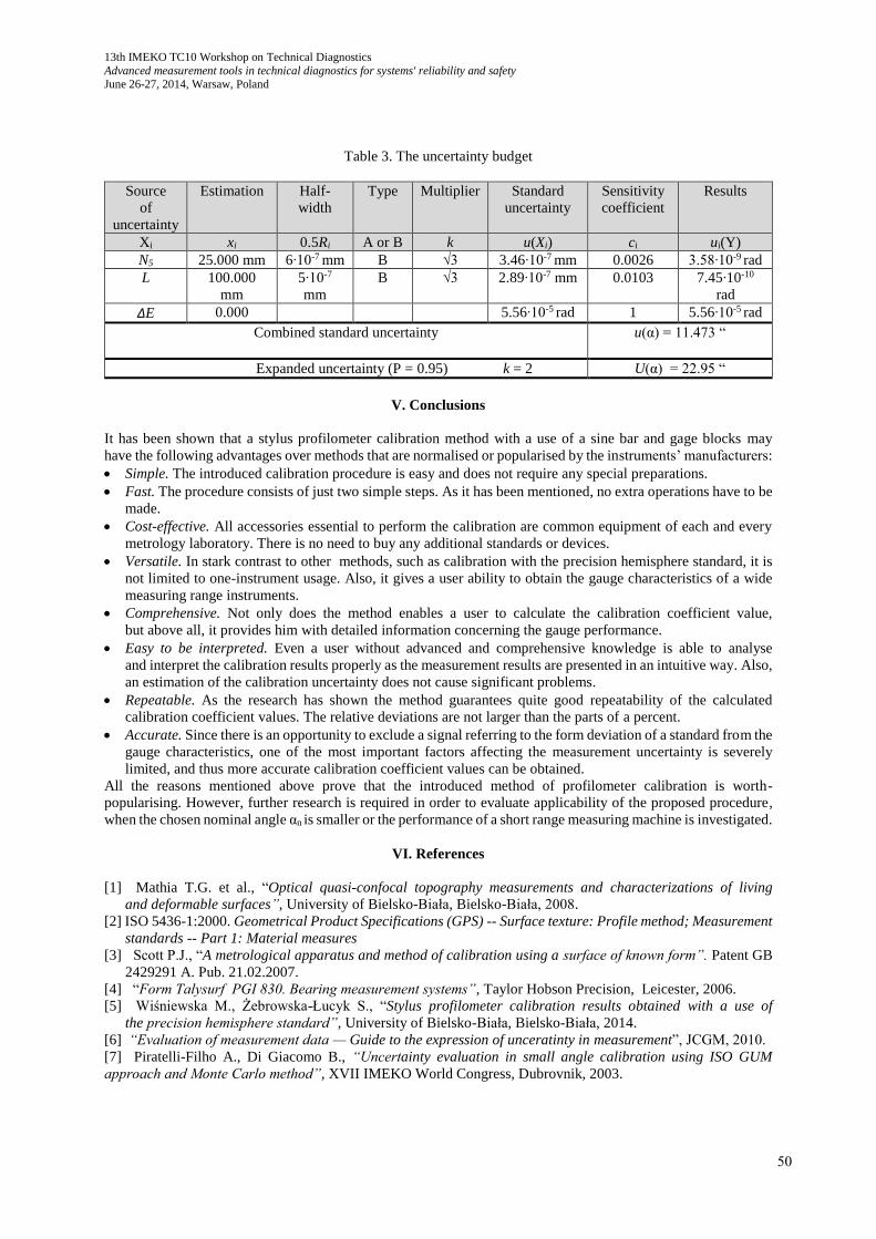
Then, the uncertainty budget referring to the conducted experiment has been created. It is shown in Table 3.
The research has shown that an impact of the gauge block nominal length and sine bar length is negligible, when
compared to a bias caused by the instrument and sine bar configuration. Also, it has been found out
that the expanded uncertainty of the measured angle α does not exceed parts of minutes. Due to this, the expanded
uncertainty of the calibration coefficient Z does not exceed thousand parts (a few per mills).
(3)
(4)
(5)
(6)
49
13th IMEKO TC10 Workshop on Technical Diagnostics
Advanced measurement tools in technical diagnostics for systems' reliability and safety June 26-27, 2014, Warsaw, Poland
Table 3. The uncertainty budget
Source
of
uncertainty
Estimation Half-
width
Type Multiplier Standard
uncertainty
Sensitivity
coefficient
Results
Xi xi 0.5Ri A or B k u(Xi) ci ui(Y)
N5 25.000 mm 6∙10-7 mm B √3 3.46∙10-7 mm 0.0026 3.58∙10-9 rad
L 100.000
mm
5∙10-7
mm
B √3 2.89∙10-7 mm 0.0103 7.45∙10-10
rad
ΔE 0.000 5.56∙10-5 rad 1 5.56∙10-5 rad
Combined standard uncertainty u(α) = 11.473 “
Expanded uncertainty (P = 0.95) k = 2 U(α) = 22.95 “
V. Conclusions
It has been shown that a stylus profilometer calibration method with a use of a sine bar and gage blocks may
have the following advantages over methods that are normalised or popularised by the instruments’ manufacturers:
Simple. The introduced calibration procedure is easy and does not require any special preparations.
Fast. The procedure consists of just two simple steps. As it has been mentioned, no extra operations have to be
made.
Cost-effective. All accessories essential to perform the calibration are common equipment of each and every
metrology laboratory. There is no need to buy any additional standards or devices.
Versatile. In stark contrast to other methods, such as calibration with the precision hemisphere standard, it is
not limited to one-instrument usage. Also, it gives a user ability to obtain the gauge characteristics of a wide
measuring range instruments.
Comprehensive. Not only does the method enables a user to calculate the calibration coefficient value,
but above all, it provides him with detailed information concerning the gauge performance.
Easy to be interpreted. Even a user without advanced and comprehensive knowledge is able to analyse
and interpret the calibration results properly as the measurement results are presented in an intuitive way. Also,
an estimation of the calibration uncertainty does not cause significant problems.
Repeatable. As the research has shown the method guarantees quite good repeatability of the calculated
calibration coefficient values. The relative deviations are not larger than the parts of a percent.
Accurate. Since there is an opportunity to exclude a signal referring to the form deviation of a standard from the
gauge characteristics, one of the most important factors affecting the measurement uncertainty is severely
limited, and thus more accurate calibration coefficient values can be obtained.
All the reasons mentioned above prove that the introduced method of profilometer calibration is worth-
popularising. However, further research is required in order to evaluate applicability of the proposed procedure,
when the chosen nominal angle αn is smaller or the performance of a short range measuring machine is investigated.
VI. References
[1] Mathia T.G. et al., “Optical quasi-confocal topography measurements and characterizations of living
and deformable surfaces”, University of Bielsko-Biała, Bielsko-Biała, 2008.
[2] ISO 5436-1:2000. Geometrical Product Specifications (GPS) -- Surface texture: Profile method; Measurement
standards -- Part 1: Material measures
[3] Scott P.J., “A metrological apparatus and method of calibration using a surface of known form”. Patent GB
2429291 A. Pub. 21.02.2007.
[4] “Form Talysurf PGI 830. Bearing measurement systems”, Taylor Hobson Precision, Leicester, 2006.
[5] Wiśniewska M., Żebrowska-Łucyk S., “Stylus profilometer calibration results obtained with a use of
the precision hemisphere standard”, University of Bielsko-Biała, Bielsko-Biała, 2014.
[6] “Evaluation of measurement data — Guide to the expression of unceratinty in measurement”, JCGM, 2010. [7] Piratelli-Filho A., Di Giacomo B., “Uncertainty evaluation in small angle calibration using ISO GUM
approach and Monte Carlo method”, XVII IMEKO World Congress, Dubrovnik, 2003.
50