Embed Size (px)
Citation preview

OTR SALES REFERENCE GUIDE
SAFETY PRECAUTIONS CONCERNING MOUNTING, DEMOUNTING AND OPERATION

i
X-Ray Spectrophotometer ONOMICHI Off-The-Road Tire Plant
OTR SALES REFERENCE GUIDE
ii
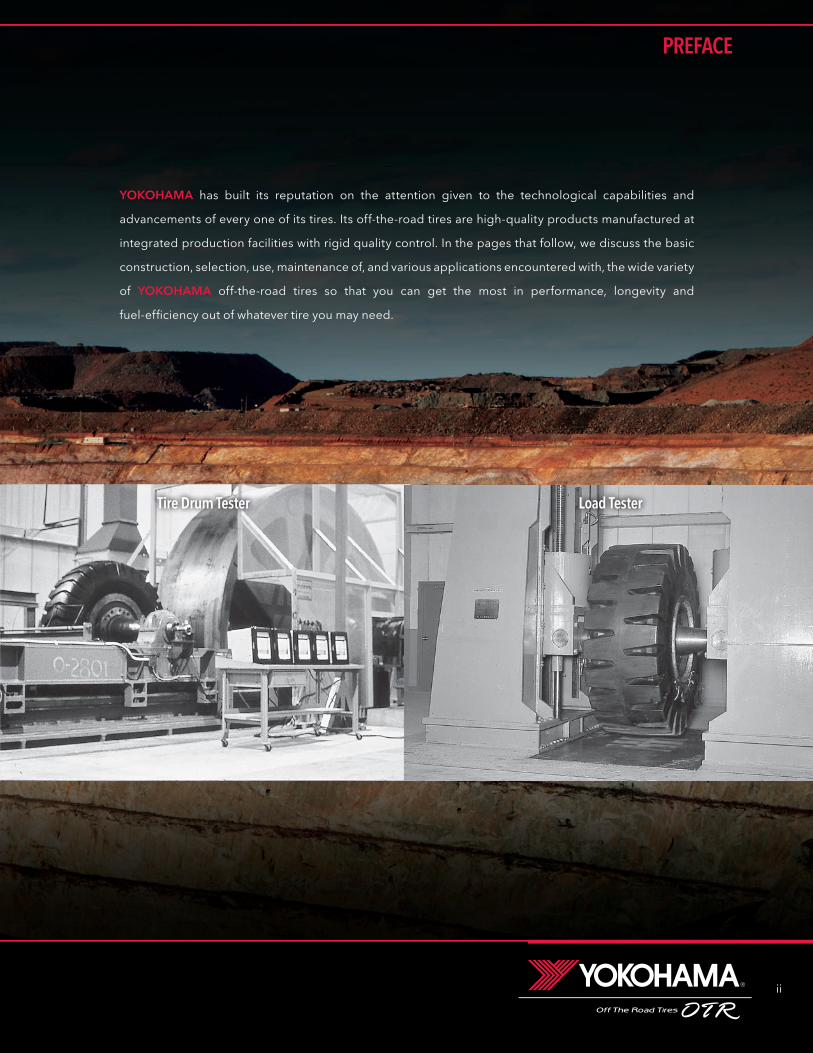
YOKOHAMA has built its reputation on the attention given to the technological capabilities and
advancements of every one of its tires. Its off-the-road tires are high-quality products manufactured at
integrated production facilities with rigid quality control. In the pages that follow, we discuss the basic
construction, selection, use, maintenance of, and various applications encountered with, the wide variety
of YOKOHAMA off-the-road tires so that you can get the most in performance, longevity and
fuel-efficiency out of whatever tire you may need.
Tire Drum Tester Load Tester
PREFACE

iii
TABLE OF CONTENTS
TRA Classification of OFF-THE-ROAD TIRES 1
Tread Pattern 1
Tread Thickness 2
Construction of OFF-THE-ROAD TIRES 2
Tire Marking (Radial) 3
Size Identification and Aspect Ratio 3
Tire Specification Code 4
Tires by Type of Vehicle 5
Load Index 7
Speed Symbol 8
Conversion Table: Star Mark to Ply Rating 8
Radial : Application
Earthmover 9
Loader & Dozer 10
Grader 11
Mobile Crane 11
Industrial 11
Radial : Technical Data
Earthmover 13
Loader & Dozer 17
Grader 19
Industrial 19
Crane 19
Appendix (Radial) 21
Bias : Application
Earthmover 23
Loader & Dozer 24
Grader 27
Compactor 27
Industrial 28
Bias : Technical Data
Earthmover 29
Loader & Dozer 37
Grader 41
Industrial 43
Wide Base Low-Seam Mining 45
Appendix (Bias) 47
Inflation Pressure 49
Load 50
Speed 50
Proper Matching of Dual-Tires 51
Road Surface Maintenance 52
Tire Problems & Major Causes 52
Instructions for Operations 53
Tire Appearance Check-up 53
Measuring Tread Wear 54Ton-Kilometer-Per-Hour
(Ton-Mile-Per-Hour) 55
Load-and-Carry Operation of
Front-End Loaders 57
Protecting Tires on Vehicle in
Highway Drive-Away 58
Handling of Tires 61
Safety Precautions for Demounting 61
Safety Precautions for Mounting 62
Safety Precautions for Operation 63
Tire Storage 64
How to Reduce Tire Costs 64
Tubes and Flaps 65
Rims 65
Valves 67
O-Rings 71
Combination Tables 73
Earthmover Data 75
Conversion Tables 78
Approximate Weight of Materials 80
Notes 81
OUTLINE OF OFF-THE-ROAD TIRES1
YOKOHAMA OFF-THE-ROAD TIRES2
TIRE MAINTENANCE3
RIMS, VALVES & O-RINGS4
MISCELLANEOUS DATA5
iv
1
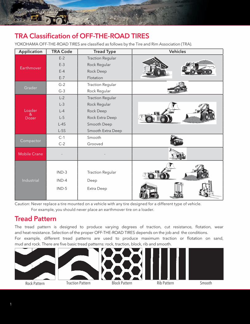
Application TRA Code Tread Type Vehicles
Earthmover
E-2 Traction Regular
E-3 Rock Regular
E-4 Rock Deep
E-7 Flotation
GraderG-2 Traction Regular
G-3 Rock Regular
Loader&
Dozer
L-2 Traction Regular
L-3 Rock Regular
L-4 Rock Deep
L-5 Rock Extra Deep
L-4S Smooth Deep
L-5S Smooth Extra Deep
CompactorC-1 Smooth
C-2 Grooved
Mobile Crane - -
Industrial
IND-3
IND-4
IND-5
Traction Regular
Deep
Extra Deep
Caution: Never replace a tire mounted on a vehicle with any tire designed for a different type of vehicle. For example, you should never place an earthmover tire on a loader.
TRA Classification of OFF-THE-ROAD TIRESYOKOHAMA OFF-THE-ROAD TIRES are classified as follows by the Tire and Rim Association (TRA).
Rock Pattern Traction Pattern Block Pattern Rib Pattern Smooth
Tread PatternThe tread pattern is designed to produce varying degrees of traction, cut resistance, flotation, wear and heat resistance. Selection of the proper OFF-THE-ROAD TIRES depends on the job and the conditions. For example, different tread patterns are used to produce maximum traction or flotation on sand, mud and rock. There are five basic tread patterns: rock, traction, block, rib and smooth.
1
2
OUTLINE OF OFF-THE-ROAD TIRES
Breaker
Tread
Sidewall
Carcass
Bead
Inner
Belt
Carcass
Inner Liner
Bead Wire
Chafer
Sidewall
Tread
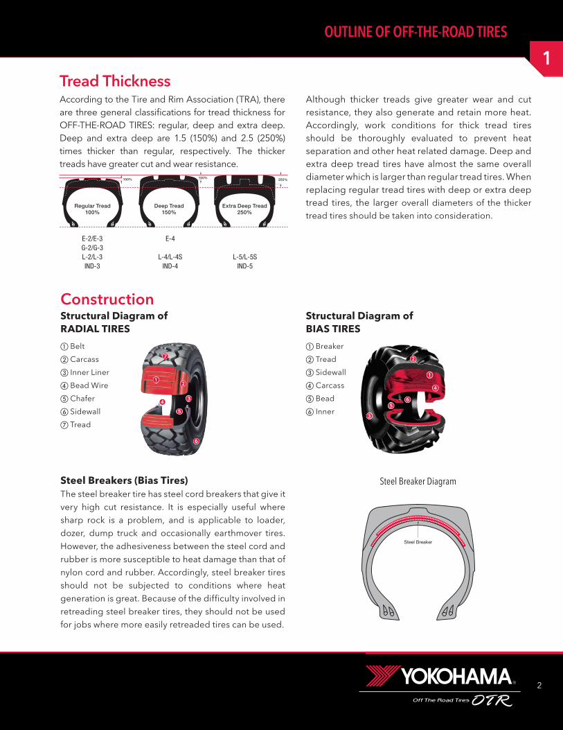
E-2/E-3G-2/G-3L-2/L-3IND-3
E-4
L-4/L-4SIND-4
L-5/L-5SIND-5
Structural Diagram of RADIAL TIRES
Structural Diagram of BIAS TIRES
Construction
Steel Breakers (Bias Tires)The steel breaker tire has steel cord breakers that give it very high cut resistance. It is especially useful where sharp rock is a problem, and is applicable to loader, dozer, dump truck and occasionally earthmover tires. However, the adhesiveness between the steel cord and rubber is more susceptible to heat damage than that of nylon cord and rubber. Accordingly, steel breaker tires should not be subjected to conditions where heat generation is great. Because of the difficulty involved in retreading steel breaker tires, they should not be used for jobs where more easily retreaded tires can be used.
Steel Breaker
Steel Breaker Diagram
Tread ThicknessAccording to the Tire and Rim Association (TRA), there are three general classifications for tread thickness for OFF-THE-ROAD TIRES: regular, deep and extra deep. Deep and extra deep are 1.5 (150%) and 2.5 (250%) times thicker than regular, respectively. The thicker treads have greater cut and wear resistance.
Although thicker treads give greater wear and cut resistance, they also generate and retain more heat. Accordingly, work conditions for thick tread tires should be thoroughly evaluated to prevent heat separation and other heat related damage. Deep and extra deep tread tires have almost the same overall diameter which is larger than regular tread tires. When replacing regular tread tires with deep or extra deep tread tires, the larger overall diameters of the thicker tread tires should be taken into consideration.
3
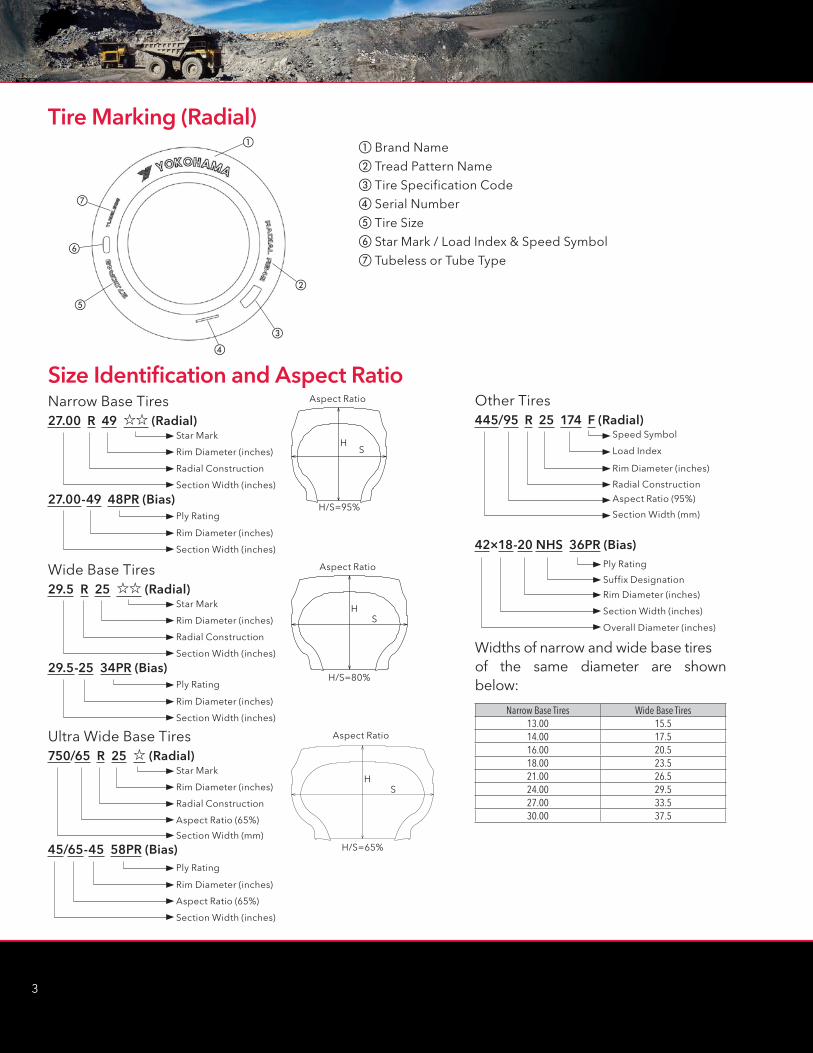
Other Tires445/95 R 25 174 F (Radial)
42×18-20 NHS 36PR (Bias)
Speed Symbol
Ply Rating
Load Index
Rim Diameter (inches)
Suffix Designation
Rim Diameter (inches)
Radial Construction
Aspect Ratio (95%)
Section Width (mm)
Section Width (inches)
Overall Diameter (inches)
Narrow Base Tires27.00 R 49 ;; (Radial)
27.00-49 48PR (Bias)
Star Mark
Ply Rating
Rim Diameter (inches)
Rim Diameter (inches)
Radial Construction
Section Width (inches)
Section Width (inches)
Aspect Ratio
H/S=95%
HS
Wide Base Tires29.5 R 25 ;; (Radial)
29.5-25 34PR (Bias)
Star Mark
Ply Rating
Rim Diameter (inches)
Rim Diameter (inches)
Radial Construction
Section Width (inches)
Section Width (inches)
HS
H/S=80%
Aspect Ratio
Ultra Wide Base Tires750/65 R 25 ; (Radial)
45/65-45 58PR (Bias)
Star Mark
Ply Rating
Rim Diameter (inches)
Rim Diameter (inches)
Radial Construction
Aspect Ratio (65%)
Section Width (mm)
Aspect Ratio (65%)
Section Width (inches)
HS
H/S=65%
Aspect Ratio
Narrow Base Tires Wide Base Tires13.00 15.514.00 17.516.00 20.518.00 23.521.00 26.524.00 29.527.00 33.530.00 37.5
Widths of narrow and wide base tires of the same diameter are shown below:
Brand Name Tread Pattern Name Tire Specification Code Serial Number Tire Size Star Mark / Load Index & Speed Symbol Tubeless or Tube Type
Tire Marking (Radial)
Size Identification and Aspect Ratio
1
4
OUTLINE OF OFF-THE-ROAD TIRES
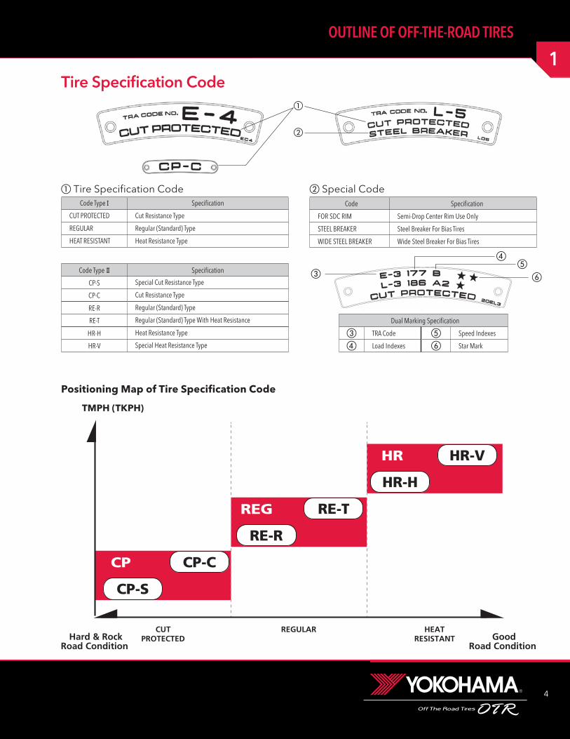
Tire Specification Code
Positioning Map of Tire Specification Code
Code Type I Specification
CUT PROTECTED Cut Resistance Type
REGULAR Regular (Standard) Type
HEAT RESISTANT Heat Resistance Type
Code Specification
FOR SDC RIM Semi-Drop Center Rim Use Only
STEEL BREAKER Steel Breaker For Bias Tires
WIDE STEEL BREAKER Wide Steel Breaker For Bias Tires
Tire Specification Code Special Code
CP-S
CP-C
RE-R
RE-T
HR-H
HR-V
Hard & RockRoad Condition
GoodRoad Condition
CUTPROTECTED
REGULAR HEATRESISTANT
CP
REG
HR
Code Type II Specification
CP-S Special Cut Resistance Type
CP-C Cut Resistance Type
RE-R Regular (Standard) Type
RE-T Regular (Standard) Type With Heat Resistance
HR-H Heat Resistance Type
HR-V Special Heat Resistance Type
Dual Marking Specification
TRA Code Speed Indexes
Load Indexes Star Mark
TMPH (TKPH)
5
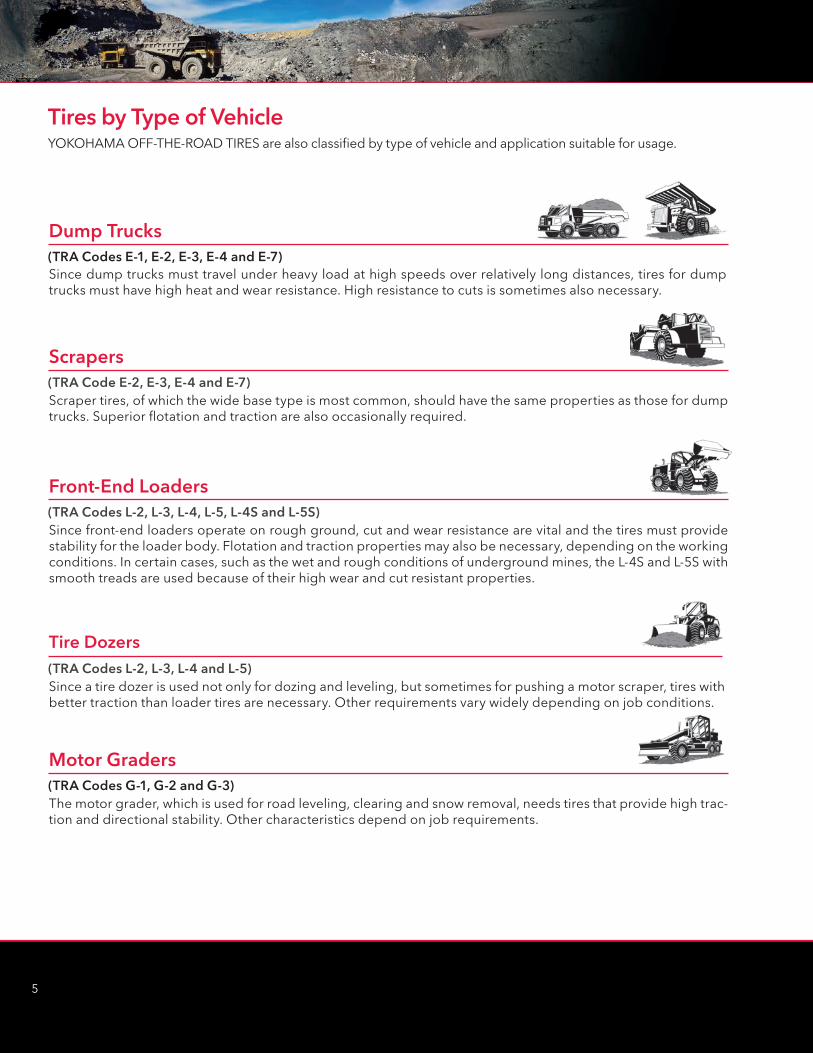
Tires by Type of VehicleYOKOHAMA OFF-THE-ROAD TIRES are also classified by type of vehicle and application suitable for usage.
Scrapers(TRA Code E-2, E-3, E-4 and E-7)Scraper tires, of which the wide base type is most common, should have the same properties as those for dump trucks. Superior flotation and traction are also occasionally required.
Front-End Loaders(TRA Codes L-2, L-3, L-4, L-5, L-4S and L-5S)Since front-end loaders operate on rough ground, cut and wear resistance are vital and the tires must provide stability for the loader body. Flotation and traction properties may also be necessary, depending on the working conditions. In certain cases, such as the wet and rough conditions of underground mines, the L-4S and L-5S with smooth treads are used because of their high wear and cut resistant properties.
Motor Graders(TRA Codes G-1, G-2 and G-3)The motor grader, which is used for road leveling, clearing and snow removal, needs tires that provide high trac-tion and directional stability. Other characteristics depend on job requirements.
Dump Trucks(TRA Codes E-1, E-2, E-3, E-4 and E-7)Since dump trucks must travel under heavy load at high speeds over relatively long distances, tires for dump trucks must have high heat and wear resistance. High resistance to cuts is sometimes also necessary.
Tire Dozers(TRA Codes L-2, L-3, L-4 and L-5)Since a tire dozer is used not only for dozing and leveling, but sometimes for pushing a motor scraper, tires with better traction than loader tires are necessary. Other requirements vary widely depending on job conditions.
1
6
OUTLINE OF OFF-THE-ROAD TIRES
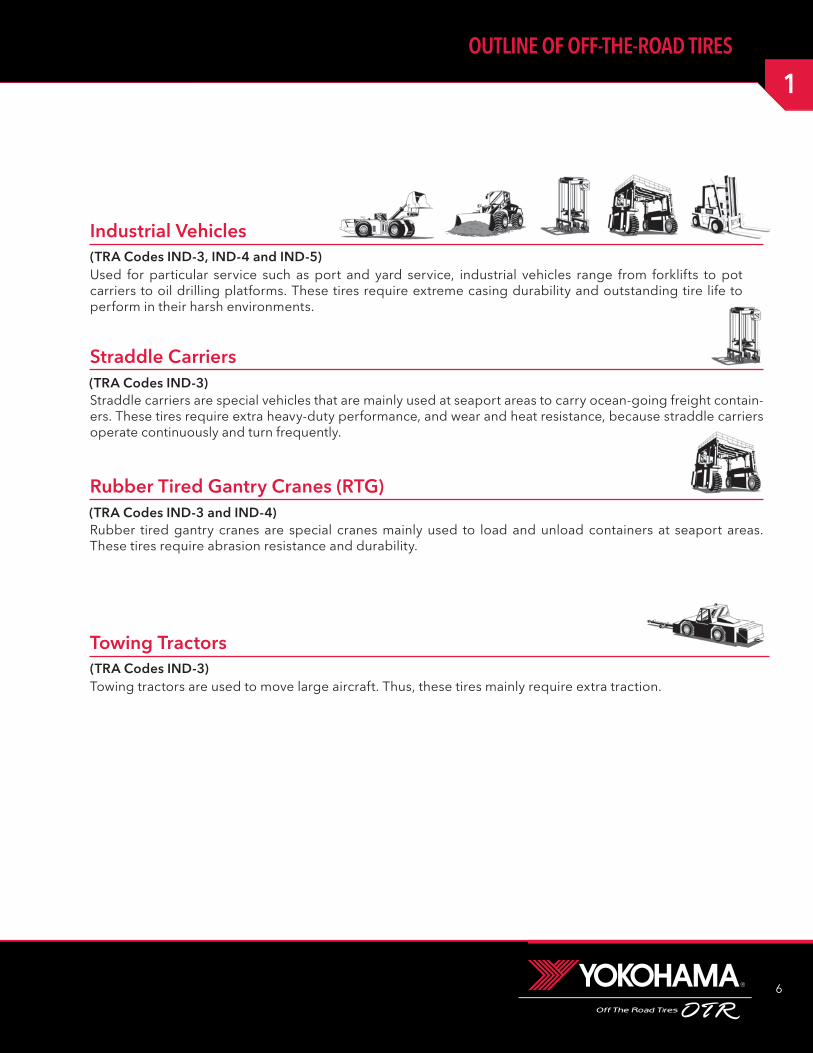
Towing Tractors(TRA Codes IND-3)Towing tractors are used to move large aircraft. Thus, these tires mainly require extra traction.
Straddle Carriers(TRA Codes IND-3)Straddle carriers are special vehicles that are mainly used at seaport areas to carry ocean-going freight contain-ers. These tires require extra heavy-duty performance, and wear and heat resistance, because straddle carriers operate continuously and turn frequently.
Rubber Tired Gantry Cranes (RTG)(TRA Codes IND-3 and IND-4)Rubber tired gantry cranes are special cranes mainly used to load and unload containers at seaport areas. These tires require abrasion resistance and durability.
Industrial Vehicles(TRA Codes IND-3, IND-4 and IND-5)Used for particular service such as port and yard service, industrial vehicles range from forklifts to pot carriers to oil drilling platforms. These tires require extreme casing durability and outstanding tire life to perform in their harsh environments.

7
L I kg lbs L I kg lbs L I kg lbs L I kg lbs L I kg lbs L I kg lbs40 140 310 90 600 1320 140 2500 5520 190 10600 23400 210 19000 41900 260 80000 17650041 145 320 91 615 1360 141 2575 5680 191 10900 24000 211 19500 43000 261 82500 18200042 150 330 92 630 1390 142 2650 5840 192 11200 24700 212 20000 44100 262 85000 18750043 155 340 93 650 1430 143 2725 6000 193 11500 25400 213 20600 45400 263 87500 19300044 160 355 94 670 1480 144 2800 6150 194 11800 26000 214 21200 46700 264 90000 19850045 165 365 95 690 1520 145 2900 6400 195 12150 26800 215 21800 48100 265 92500 20400046 170 375 96 710 1570 146 3000 6600 196 12500 27600 216 22400 49400 266 95000 20950047 175 385 97 730 1610 147 3075 6800 197 12850 28300 217 23000 50700 267 97500 21495048 180 395 98 750 1650 148 3150 6950 198 13200 29100 218 23600 52000 268 100000 22050049 185 410 99 775 1710 149 3250 7150 199 13600 30000 219 24300 53600 269 103000 227500
50 190 420 100 800 1760 150 3350 7400 200 14000 30900 220 25000 55100 270 106000 23350051 195 430 101 825 1820 151 3450 7600 201 14500 32000 221 25750 56800 271 109000 24050052 200 440 102 850 1870 152 3550 7850 202 15000 33100 222 26500 58400 272 112000 24700053 206 455 103 875 1930 153 3650 8050 203 15500 34200 223 27250 60000 273 115000 25350054 212 465 104 900 1980 154 3750 8250 204 16000 35300 224 28000 61500 274 118000 26000055 218 480 105 925 2040 155 3875 8550 205 16500 36400 225 29000 64000 275 121500 26800056 224 495 106 950 2090 156 4000 8800 206 17000 37500 226 30000 66000 276 125000 27600057 230 505 107 975 2150 157 4125 9100 207 17500 38600 227 30750 68000 277 128500 28300058 236 520 108 1000 2200 158 4250 9350 208 18000 39700 228 31500 69500 278 132000 29100059 243 535 109 1030 2270 159 4375 9650 209 18500 40800 229 32500 71500 279 136000 300000
60 250 550 110 1060 2340 160 4500 9900 210 19000 41900 230 33500 7400061 257 565 111 1090 2400 161 4625 10200 211 19500 43000 231 34500 7600062 265 585 112 1120 2470 162 4750 10500 212 20000 44100 232 35500 7850063 272 600 113 1150 2540 163 4875 10700 213 20600 45400 233 36500 8050064 280 615 114 1180 2600 164 5000 11000 214 21200 46700 234 37500 8250065 290 640 115 1215 2680 165 5150 11400 215 21800 48100 235 38750 8550066 300 660 116 1250 2760 166 5300 11700 216 22400 49400 236 40000 8800067 307 675 117 1285 2830 167 5450 12000 217 23000 50700 237 41250 9100068 315 695 118 1320 2910 168 5600 12300 218 23600 52000 238 42500 9350069 325 715 119 1360 3000 169 5800 12800 219 24300 53600 239 43750 96500
70 335 740 120 1400 3080 170 6000 13200 220 25000 55100 240 45000 9900071 345 760 121 1450 3200 171 6150 13600 221 25750 56800 241 46250 10200072 355 785 122 1500 3300 172 6300 13900 222 26500 58400 242 47500 10450073 365 805 123 1550 3420 173 6500 14300 223 27250 60000 243 48750 10750074 375 825 124 1600 3520 174 6700 14800 224 28000 61500 244 50000 11000075 387 855 125 1650 3640 175 6900 15200 225 29000 64000 245 51500 11350076 400 880 126 1700 3740 176 7100 15700 226 30000 66000 246 53000 11700077 412 910 127 1750 3860 177 7300 16100 227 30750 68000 247 54500 12000078 425 935 128 1800 3960 178 7500 16500 228 31500 69500 248 56000 12350079 437 965 129 1850 4080 179 7750 17100 229 32500 71500 249 58000 128000
80 450 990 130 1900 4180 180 8000 17600 230 33500 74000 250 60000 13250081 462 1020 131 1950 4300 181 8250 18200 231 34500 76000 251 61500 13550082 475 1050 132 2000 4400 182 8500 18700 232 35500 78500 252 63000 13900083 487 1070 133 2060 4540 183 8750 19300 233 36500 80500 253 65000 14350084 500 1100 134 2120 4680 184 9000 19800 234 37500 82500 254 67000 14550085 515 1140 135 2180 4800 185 9250 20400 235 38750 85500 255 69000 15000086 530 1170 136 2240 4940 186 9500 20900 236 40000 88000 256 71000 15650087 545 1200 137 2300 5080 187 9750 21500 237 41250 91000 257 73000 16100088 560 1230 138 2360 5200 188 10000 22000 238 42500 93500 258 75000 16550089 580 1280 139 2430 5360 189 10300 22700 239 43750 96500 259 77500 171000
Load IndexThe Load Index is an international numerical code associated with the maximum load a tire can carry at the speed indicated by its Speed Symbol under service specified conditions.
1
8
OUTLINE OF OFF-THE-ROAD TIRES
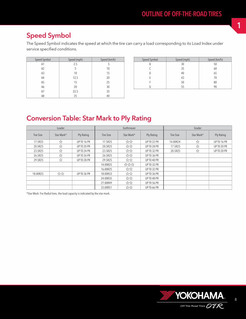
Speed Symbol Speed (mph) Speed (km/h)A1 2.5 5A2 5 10A3 10 15A4 12.5 20A5 15 25A6 20 30A7 22.5 35A8 25 40
Speed Symbol Speed (mph) Speed (km/h)B 30 50C 35 60D 40 65E 43 70F 50 80G 55 90
Conversion Table: Star Mark to Ply RatingLoader Earthmover Grader
Tire Size Star Mark* Ply Rating Tire Size Star Mark* Ply Rating Tire Size Star Mark* Ply Rating
17.5R25 UP T0 16 PR 17.5R25 UP T0 22 PR 14.00R24 UP T0 16 PR 20.5R25 UP T0 20 PR 20.5R25 UP T0 28 PR 17.5R25 UP T0 20 PR 23.5R25 UP T0 24 PR 23.5R25 UP T0 32 PR 20.5R25 UP T0 20 PR 26.5R25 UP T0 26 PR 26.5R25 UP T0 36 PR 29.5R25 UP T0 28 PR 29.5R25 UP T0 40 PR
14.00R25 UP T0 32 PR 16.00R25 UP T0 32 PR
18.00R25 UP T0 36 PR 18.00R33 UP T0 36 PR 24.00R35 UP T0 48 PR 27.00R49 UP T0 56 PR33.00R51 UP T0 66 PR
*Star Mark: For Radial tires, the load capacity is indicated by the star mark.
Speed SymbolThe Speed Symbol indicates the speed at which the tire can carry a load corresponding to its Load Index under service specified conditions.
9
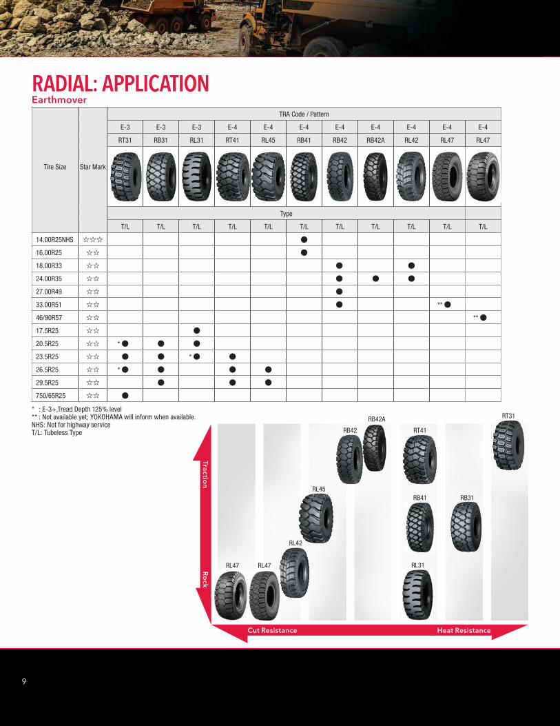
RADIAL: APPLICATION
Tire Size Star Mark
TRA Code / Pattern
E-3 E-3 E-3 E-4 E-4 E-4 E-4 E-4 E-4 E-4 E-4
RT31 RB31 RL31 RT41 RL45 RB41 RB42 RB42A RL42 RL47 RL47
Type
T/L T/L T/L T/L T/L T/L T/L T/L T/L T/L T/L
14.00R25NHS ;;; V
16.00R25 ;; V
18.00R33 ;; V V
24.00R35 ;; V V V
27.00R49 ;; V
33.00R51 ;; V ** V
46/90R57 ;; ** V
17.5R25 ;; V
20.5R25 ;; * V V V
23.5R25 ;; V V * V V
26.5R25 ;; * V V V V
29.5R25 ;; V V V
750/65R25 ;; V
* : E-3+,Tread Depth 125% level** : Not available yet; YOKOHAMA will inform when available.NHS: Not for highway serviceT/L: Tubeless Type
Earthmover
RB42A
Cut Resistance Heat Resistance
Traction
Ro
ck
RT31
RB31
RT41RB42
RL45
RL42
RB41
RL31RL47RL47
2
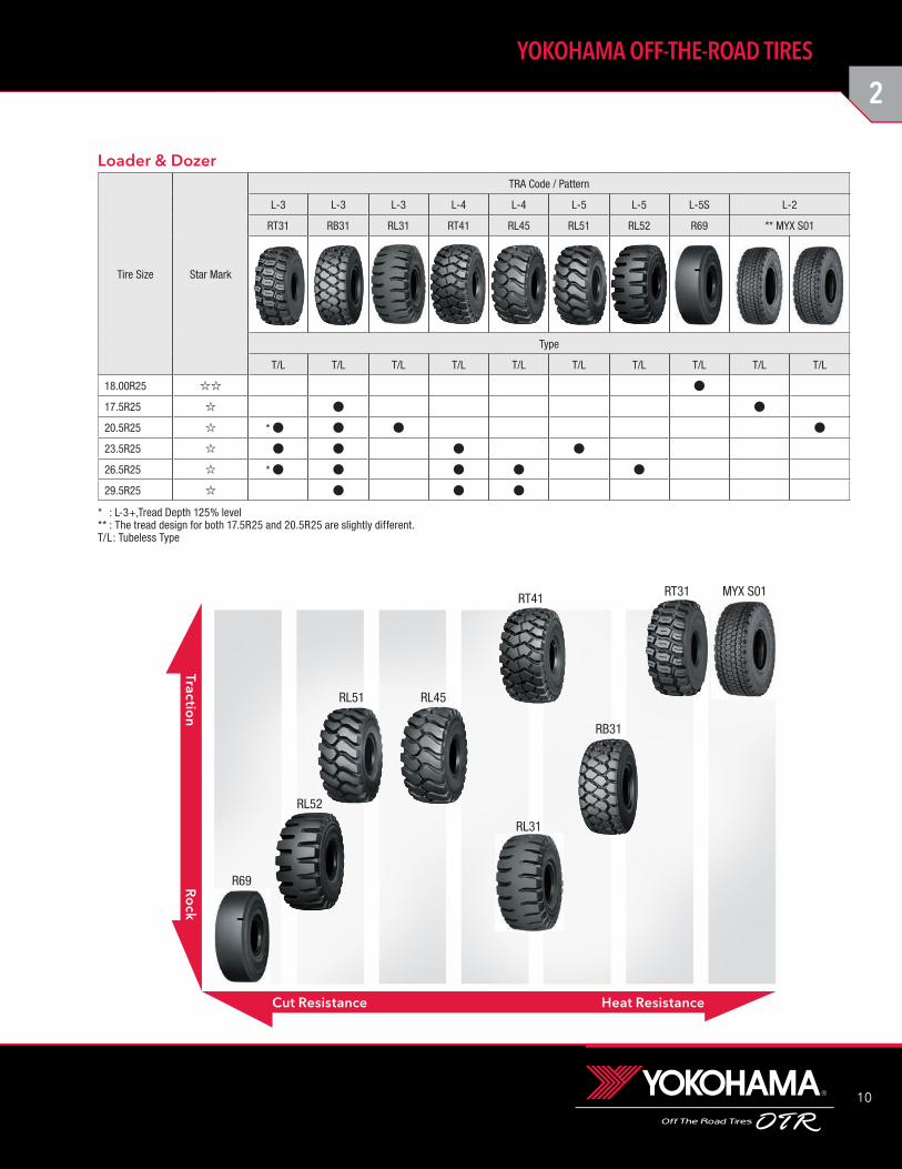
10
YOKOHAMA OFF-THE-ROAD TIRES
Tire Size Star Mark
TRA Code / Pattern
L-3 L-3 L-3 L-4 L-4 L-5 L-5 L-5S L-2
RT31 RB31 RL31 RT41 RL45 RL51 RL52 R69 ** MYX S01
Type
T/L T/L T/L T/L T/L T/L T/L T/L T/L T/L
18.00R25 ;; V
17.5R25 ; V V
20.5R25 ; * V V V V
23.5R25 ; V V V V
26.5R25 ; * V V V V V
29.5R25 ; V V V
* : L-3+,Tread Depth 125% level** : The tread design for both 17.5R25 and 20.5R25 are slightly different.T/L : Tubeless Type
Loader & Dozer
RT31
RB31
RT41
RL45
RL52
RL51
RL31
Heat ResistanceCut Resistance
Traction
Ro
ck
R69
MYX S01
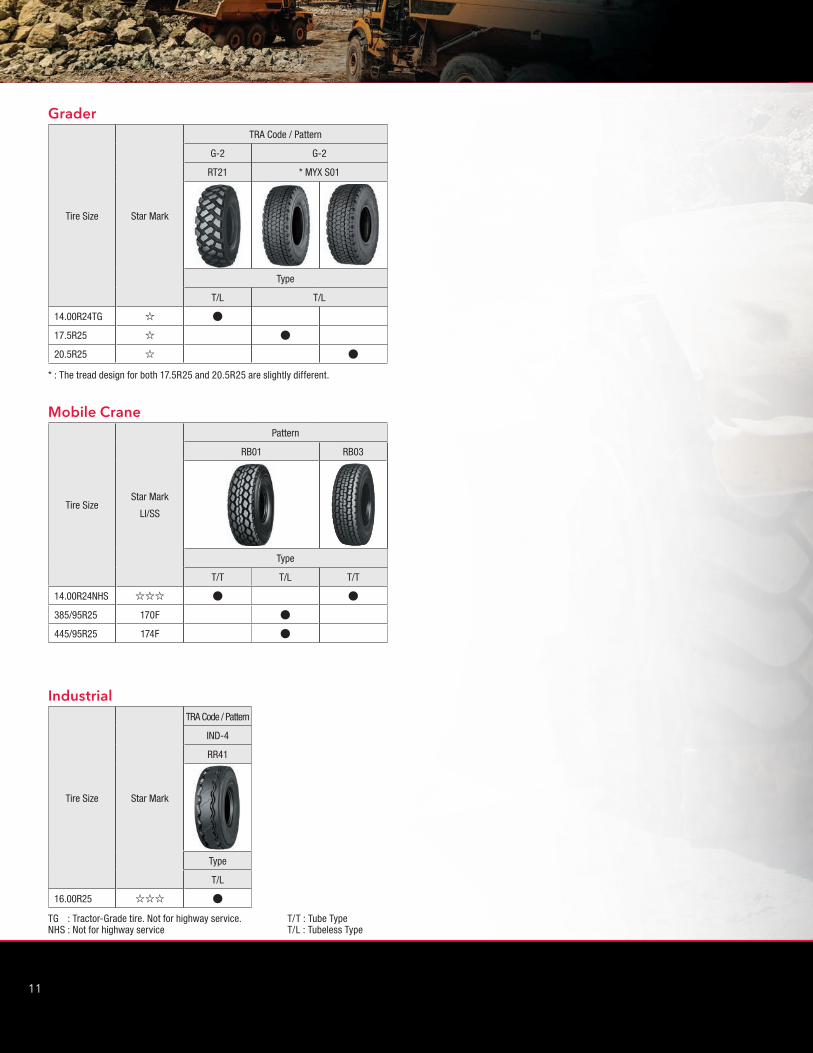
11
Tire Size Star Mark
TRA Code / Pattern
G-2 G-2
RT21 * MYX S01
Type
T/L T/L
14.00R24TG ; V
17.5R25 ; V
20.5R25 ; V
* : The tread design for both 17.5R25 and 20.5R25 are slightly different.
Grader
Tire SizeStar Mark
LI/SS
Pattern
RB01 RB03
Type
T/T T/L T/T
14.00R24NHS ;;; V V
385/95R25 170F V
445/95R25 174F V
Mobile Crane
TG : Tractor-Grade tire. Not for highway service. T/T : Tube TypeNHS : Not for highway service T/L : Tubeless Type
Tire Size Star Mark
TRA Code / Pattern
IND-4
RR41
Type
T/L
16.00R25 ;;; V
Industrial
2
12
YOKOHAMA OFF-THE-ROAD TIRES

13
TG: Tractor-Grade tire. Not for highway service.NHS: Not for highway service.
PSI × 0.0703 = kg/cm2 POUND × 0.4536 = kg PSI × 6.895 = kPa
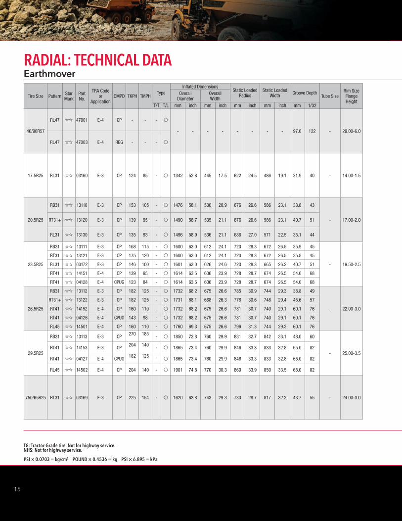
14.00R25 RB41 ;;; 04153 E-4 REG 119 82 - v 1405 55.3 393 15.5 652 25.7 431 17.0 38.0 48 - 10.00-1.5
16.00R25 RB41 ;; 04150 E-4 CP 124 85 - v 1532 60.3 450 17.7 706 27.8 500 19.7 45.1 57 - 11.25-2.0
18.00R33
RB42 ;; 04201 E-4 CP 168 115 - v1870 73.6 507 20.0 857 33.7 569 22.4 55.3 70
- 13.00-2.5RB42 ;; 14210 E-4 HR 250 171 - v
RL42 ;; 42000 E-4 CP 168 115 - v1870 73.6 507 20.0 857 33.7 569 22.4 50.0 63
RL42 ;; 42008 E-4 HR 250 171 - v
24.00R35
RB42 ;; 04210 E-4 CPS 253 173 - v
2173 85.4 656 25.8 978 38.5 745 29.3 63.5 80
- 17.00-3.5
RB42 ;; 04203 E-4 CP 277 190 - v
RB42 ;; 04206 E-4 REG 304 208 - v
RB42 ;; 04216 E-4 HR 422 289 - v
RB42A ;; 04214 E-4 CPS 253 173 - v
2180 85.8 666 26.2 980 38.6 748 29.4 63.5 80RB42A ;; 04211 E-4 CP 277 190 - v
RB42A ;; 04212 E-4 REG 304 208 - v
RL42 ;; 42006 E-4 CP 277 190 - v2163 85.2 647 25.5 978 38.5 749 29.5 58.7 74
RL42 ;; 42007 E-4 HR 422 289 - v
27.00R49
RB42 ;; 04209 E-4 CPS 350 240 - v
2683 105.6 735 28.9 1220 48.0 830 32.7 73.7 93 - 19.50-4.0RB42 ;; 04204 E-4 CP 430 295 - v
RB42 ;; 04205 E-4 REG 535 367 - v
RB42 ;; 04213 E-4 HR 615 422 - v
33.00R51
RB42 ;; 04215 E-4 CPS 480 329 - v
3061 120.5 920 36.2 1380 54.3 1021 40.2 91.0 115
- 24.00-5.0
RB42 ;; 04207 E-4 CP 600 411 - v
RB42 ;; 04208 E-4 REG 680 466 - v
RL47 ;; 47006 E-4 CP 590 404 - v3055 120.3 920 36.2 1375 54.1 1045 41.1 88.0 111
RL47 ;; 47005 E-4 REG 670 459 - v
Tire Size Pattern Star Mark
Part No.
TRA Code or
ApplicationCMPD TKPH TMPH
TypeInflated Dimensions
Static Loaded Radius
Static Loaded Width Groove Depth
Tube SizeRim Size Flange Height
Overall Diameter
Overall Width
T/T T/L mm inch mm inch mm inch mm inch mm 1/32
EarthmoverRADIAL: TECHNICAL DATA
2
14
YOKOHAMA OFF-THE-ROAD TIRES
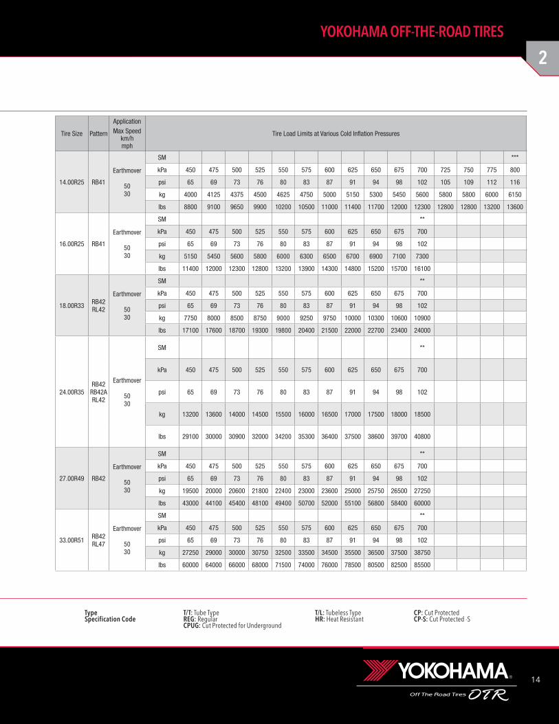
Type T/T: Tube Type T/L: Tubeless Type CP: Cut Protected Specification Code REG: Regular HR: Heat Resistant CP-S: Cut Protected -S CPUG: Cut Protected for Underground
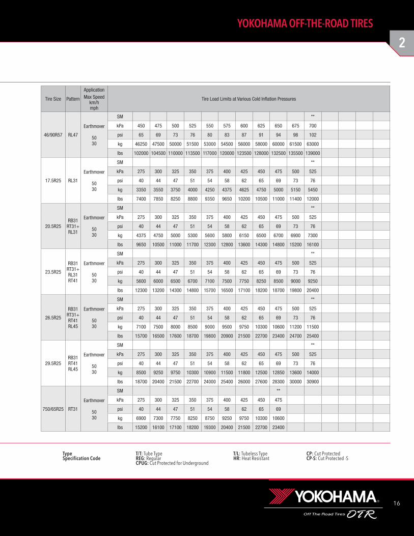
14.00R25 RB41
Earthmover
5030
SM ***
kPa 450 475 500 525 550 575 600 625 650 675 700 725 750 775 800
psi 65 69 73 76 80 83 87 91 94 98 102 105 109 112 116
kg 4000 4125 4375 4500 4625 4750 5000 5150 5300 5450 5600 5800 5800 6000 6150
lbs 8800 9100 9650 9900 10200 10500 11000 11400 11700 12000 12300 12800 12800 13200 13600
16.00R25 RB41
Earthmover
5030
SM **
kPa 450 475 500 525 550 575 600 625 650 675 700
psi 65 69 73 76 80 83 87 91 94 98 102
kg 5150 5450 5600 5800 6000 6300 6500 6700 6900 7100 7300
lbs 11400 12000 12300 12800 13200 13900 14300 14800 15200 15700 16100
18.00R33 RB42RL42
Earthmover
5030
SM **
kPa 450 475 500 525 550 575 600 625 650 675 700
psi 65 69 73 76 80 83 87 91 94 98 102
kg 7750 8000 8500 8750 9000 9250 9750 10000 10300 10600 10900
lbs 17100 17600 18700 19300 19800 20400 21500 22000 22700 23400 24000
24.00R35RB42
RB42ARL42
Earthmover
5030
SM **
kPa 450 475 500 525 550 575 600 625 650 675 700
psi 65 69 73 76 80 83 87 91 94 98 102
kg 13200 13600 14000 14500 15500 16000 16500 17000 17500 18000 18500
lbs 29100 30000 30900 32000 34200 35300 36400 37500 38600 39700 40800
27.00R49 RB42
Earthmover
5030
SM **
kPa 450 475 500 525 550 575 600 625 650 675 700
psi 65 69 73 76 80 83 87 91 94 98 102
kg 19500 20000 20600 21800 22400 23000 23600 25000 25750 26500 27250
lbs 43000 44100 45400 48100 49400 50700 52000 55100 56800 58400 60000
33.00R51 RB42RL47
Earthmover
5030
SM **
kPa 450 475 500 525 550 575 600 625 650 675 700
psi 65 69 73 76 80 83 87 91 94 98 102
kg 27250 29000 30000 30750 32500 33500 34500 35500 36500 37500 38750
lbs 60000 64000 66000 68000 71500 74000 76000 78500 80500 82500 85500
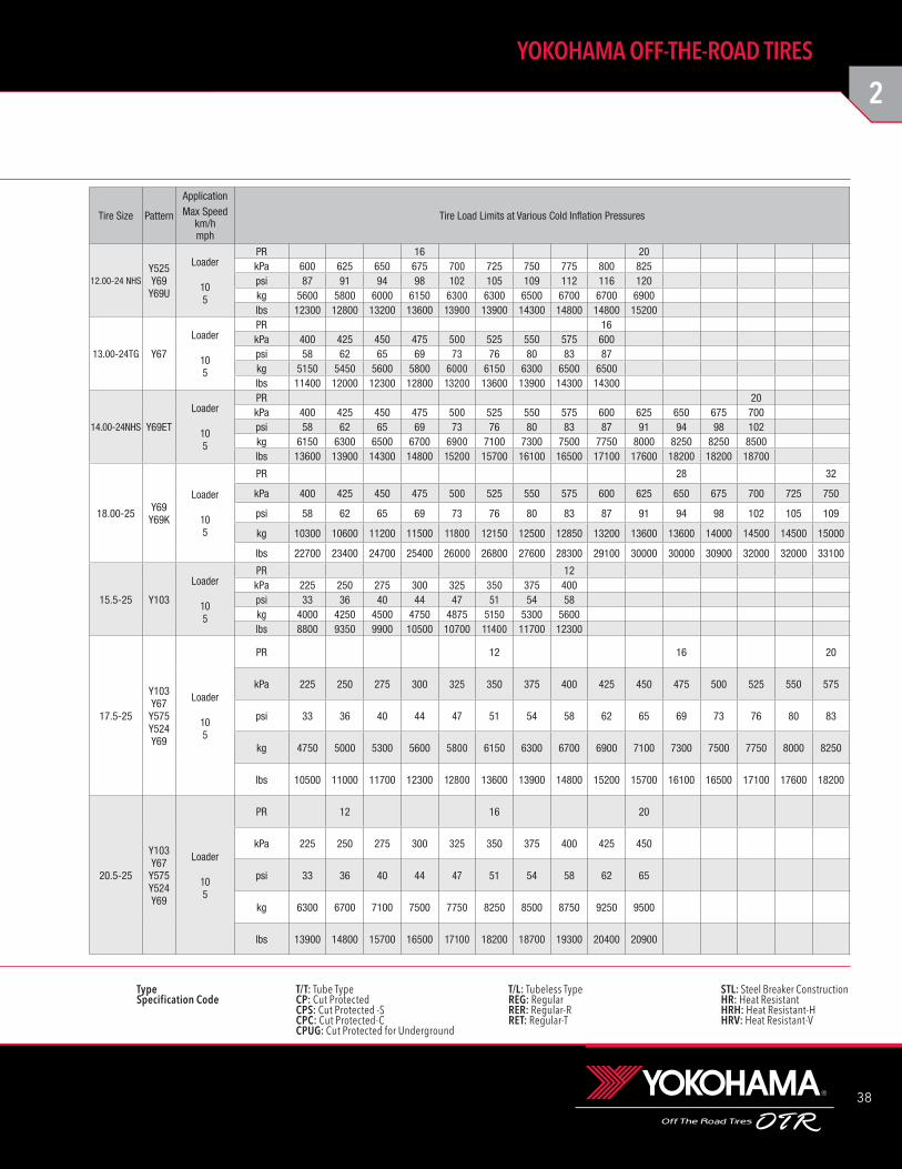
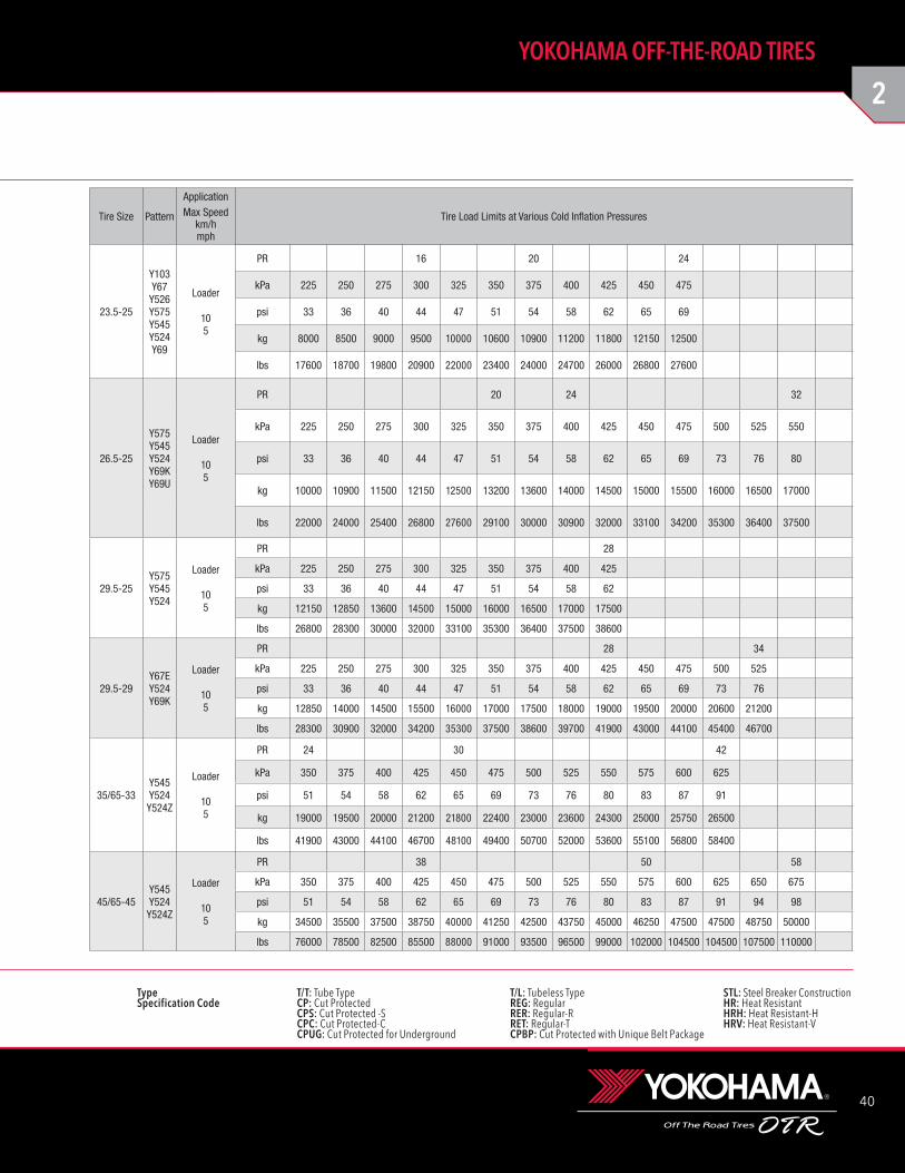
Tire Size Pattern
ApplicationMax Speed
km/hmph
Tire Load Limits at Various Cold Inflation Pressures
15
TG: Tractor-Grade tire. Not for highway service.NHS: Not for highway service.
PSI × 0.0703 = kg/cm2 POUND × 0.4536 = kg PSI × 6.895 = kPa
EarthmoverRADIAL: TECHNICAL DATA
Tire Size Pattern Star Mark
Part No.
TRA Code or
ApplicationCMPD TKPH TMPH
TypeInflated Dimensions
Static Loaded Radius
Static Loaded Width Groove Depth
Tube SizeRim Size Flange Height
Overall Diameter
Overall Width
T/T T/L mm inch mm inch mm inch mm inch mm 1/32
46/90R57
RL47 ;; 47001 E-4 CP - - - v
- - - - - - - - 97.0 122 - 29.00-6.0
RL47 ;; 47003 E-4 REG - - - v
17.5R25 RL31 ;; 03160 E-3 CP 124 85 - v 1342 52.8 445 17.5 622 24.5 486 19.1 31.9 40 - 14.00-1.5
20.5R25
RB31 ;; 13110 E-3 CP 153 105 - v 1476 58.1 530 20.9 676 26.6 586 23.1 33.8 43
- 17.00-2.0RT31+ ;; 13120 E-3 CP 139 95 - v 1490 58.7 535 21.1 676 26.6 586 23.1 40.7 51
RL31 ;; 13130 E-3 CP 135 93 - v 1496 58.9 536 21.1 686 27.0 571 22.5 35.1 44
23.5R25
RB31 ;; 13111 E-3 CP 168 115 - v 1600 63.0 612 24.1 720 28.3 672 26.5 35.9 45
- 19.50-2.5
RT31 ;; 13121 E-3 CP 175 120 - v 1600 63.0 612 24.1 720 28.3 672 26.5 35.8 45
RL31 ;; 03172 E-3 CP 146 100 - v 1601 63.0 626 24.6 720 28.3 665 26.2 40.7 51
RT41 ;; 14151 E-4 CP 139 95 - v 1614 63.5 606 23.9 728 28.7 674 26.5 54.0 68
RT41 ;; 04128 E-4 CPUG 123 84 - v 1614 63.5 606 23.9 728 28.7 674 26.5 54.0 68
26.5R25
RB31 ;; 13112 E-3 CP 182 125 - v 1732 68.2 675 26.6 785 30.9 744 29.3 38.8 49
- 22.00-3.0
RT31+ ;; 13122 E-3 CP 182 125 - v 1731 68.1 668 26.3 778 30.6 748 29.4 45.6 57
RT41 ;; 14152 E-4 CP 160 110 - v 1732 68.2 675 26.6 781 30.7 740 29.1 60.1 76
RT41 ;; 04126 E-4 CPUG 143 98 - v 1732 68.2 675 26.6 781 30.7 740 29.1 60.1 76
RL45 ;; 14501 E-4 CP 160 110 - v 1760 69.3 675 26.6 796 31.3 744 29.3 60.1 76
29.5R25
RB31 ;; 13113 E-3 CP 270 185 - v 1850 72.8 760 29.9 831 32.7 842 33.1 48.0 60
- 25.00-3.5RT41 ;; 14153 E-3 CP 204 140 - v 1865 73.4 760 29.9 846 33.3 833 32.8 65.0 82
RT41 ;; 04127 E-4 CPUG 182 125 - v 1865 73.4 760 29.9 846 33.3 833 32.8 65.0 82
RL45 ;; 14502 E-4 CP 204 140 - v 1901 74.8 770 30.3 860 33.9 850 33.5 65.0 82
750/65R25 RT31 ;; 03169 E-3 CP 225 154 - v 1620 63.8 743 29.3 730 28.7 817 32.2 43.7 55 - 24.00-3.0
2
16
YOKOHAMA OFF-THE-ROAD TIRES
Type T/T: Tube Type T/L: Tubeless Type CP: Cut Protected Specification Code REG: Regular HR: Heat Resistant CP-S: Cut Protected -S CPUG: Cut Protected for Underground
46/90R57 RL47
Earthmover
5030
SM **
kPa 450 475 500 525 550 575 600 625 650 675 700
psi 65 69 73 76 80 83 87 91 94 98 102
kg 46250 47500 50000 51500 53000 54500 56000 58000 60000 61500 63000
lbs 102000 104500 110000 113500 117000 120000 123500 128000 132500 135500 139000
17.5R25 RL31
Earthmover
5030
SM **
kPa 275 300 325 350 375 400 425 450 475 500 525
psi 40 44 47 51 54 58 62 65 69 73 76
kg 3350 3550 3750 4000 4250 4375 4625 4750 5000 5150 5450
lbs 7400 7850 8250 8800 9350 9650 10200 10500 11000 11400 12000
20.5R25RB31
RT31+RL31
Earthmover
5030
SM **
kPa 275 300 325 350 375 400 425 450 475 500 525
psi 40 44 47 51 54 58 62 65 69 73 76
kg 4375 4750 5000 5300 5600 5800 6150 6500 6700 6900 7300
lbs 9650 10500 11000 11700 12300 12800 13600 14300 14800 15200 16100
23.5R25
RB31RT31+RL31RT41
Earthmover
5030
SM **
kPa 275 300 325 350 375 400 425 450 475 500 525
psi 40 44 47 51 54 58 62 65 69 73 76
kg 5600 6000 6500 6700 7100 7500 7750 8250 8500 9000 9250
lbs 12300 13200 14300 14800 15700 16500 17100 18200 18700 19800 20400
26.5R25
RB31RT31+RT41RL45
Earthmover
5030
SM **
kPa 275 300 325 350 375 400 425 450 475 500 525
psi 40 44 47 51 54 58 62 65 69 73 76
kg 7100 7500 8000 8500 9000 9500 9750 10300 10600 11200 11500
lbs 15700 16500 17600 18700 19800 20900 21500 22700 23400 24700 25400
29.5R25RB31RT41RL45
Earthmover
5030
SM **
kPa 275 300 325 350 375 400 425 450 475 500 525
psi 40 44 47 51 54 58 62 65 69 73 76
kg 8500 9250 9750 10300 10900 11500 11800 12500 12850 13600 14000
lbs 18700 20400 21500 22700 24000 25400 26000 27600 28300 30000 30900
750/65R25 RT31
Earthmover
5030
SM **
kPa 275 300 325 350 375 400 425 450 475
psi 40 44 47 51 54 58 62 65 69
kg 6900 7300 7750 8250 8750 9250 9750 10300 10600
lbs 15200 16100 17100 18200 19300 20400 21500 22700 23400
Tire Size Pattern
ApplicationMax Speed
km/hmph
Tire Load Limits at Various Cold Inflation Pressures
17
TG: Tractor-Grade tire. Not for highway service.NHS: Not for highway service.
PSI × 0.0703 = kg/cm2 POUND × 0.4536 = kg PSI × 6.895 = kPa
Loader & DozerRADIAL: TECHNICAL DATA
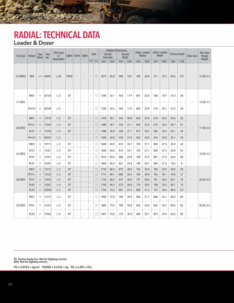
Tire Size Pattern Star Mark
Part No.
TRA Code or
ApplicationCMPD TKPH TMPH
TypeInflated Dimensions
Static Loaded Radius
Static Loaded Width Groove Depth
Tube SizeRim Size Flange Height
Overall Diameter
Overall Width
T/T T/L mm inch mm inch mm inch mm inch mm 1/32
18.00R25 R69 ;; 46901 L-5S CPUG - - - v 1673 65.9 500 19.7 760 29.9 571 22.5 85.0 107 - 13.00-2.5
17.5R25
RB31 ; 03150 L-3 CP - - - v 1348 53.1 442 17.4 607 23.9 500 19.7 31.0 39
- 14.00-1.5
MYX S01 ; 00290 L-2 - - - - v 1334 52.5 445 17.5 600 23.6 510 20.1 27.2 34
20.5R25
RB31 ; 13110 L-3 CP - - - v 1476 58.1 530 20.9 658 25.9 610 24.0 33.8 43
- 17.00-2.0RT31+ ; 13120 L-3 CP - - - v 1490 58.7 535 21.1 658 25.9 610 24.0 40.7 51
RL31 ; 13130 L-3 CP - - - v 1496 58.9 536 21.1 673 26.5 595 23.4 35.1 44
MYX S01 ; 00291 L-2 - - - - v 1494 58.8 534 21.0 655 25.8 610 24.0 30.1 38
23.5R25
RB31 ; 13111 L-3 CP - - - v 1600 63.0 612 24.1 703 27.7 694 27.3 35.9 45
- 19.50-2.5RT31 ; 13121 L-3 CP - - - v 1600 63.0 612 24.1 703 27.7 694 27.3 35.8 45
RT41 ; 14151 L-4 CP - - - v 1614 63.5 606 23.9 708 27.9 691 27.2 54.0 68
RL51 ; 51501 L-5 CP - - - v 1658 65.3 621 24.4 740 29.1 694 27.3 78.3 9
26.5R25
RB31 ; 13112 L-3 CP - v 1732 68.2 675 26.6 763 30.0 760 29.9 38.8 49
- 22.00-3.0
RT31+ ; 13122 L-3 CP - v 1731 68.1 668 26.3 760 29.9 765 30.1 45.6 57
RT41 ; 14152 L-4 CP - v 1732 68.2 675 26.6 757 29.8 761 30.0 60.1 76
RL45 ; 14501 L-4 CP - v 1760 69.3 675 26.6 776 30.6 769 30.3 60.1 76
RL52 ; 52090 L-5 CP - v 1784 70.2 697 27.4 800 31.5 737 29.0 96.0 121
29.5R25
RB31 ; 13113 L-3 CP - - - v 1850 72.8 760 29.9 806 31.7 866 34.1 48.0 60
- 25.00-3.5RT41 ; 14153 L-3 CP - - - v 1865 73.4 760 29.9 833 32.8 855 33.7 65.0 82
RL45 ; 14502 L-4 CP - - - v 1901 74.8 770 30.3 840 33.1 873 34.4 65.0 82
2
18
YOKOHAMA OFF-THE-ROAD TIRES
Type T/T: Tube Type T/L: Tubeless Type CP: Cut Protected Specification Code REG: Regular HR: Heat Resistant CP-S: Cut Protected -S CPUG: Cut Protected for Underground
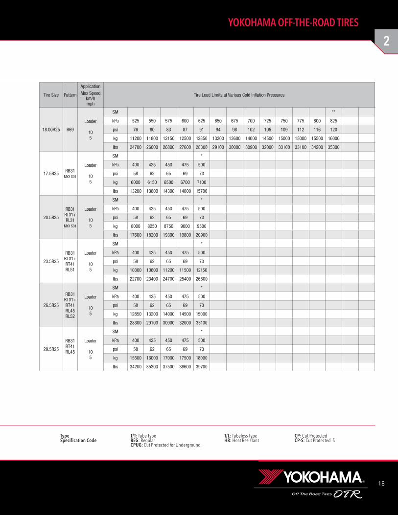
18.00R25 R69
Loader
105
SM **
kPa 525 550 575 600 625 650 675 700 725 750 775 800 825
psi 76 80 83 87 91 94 98 102 105 109 112 116 120
kg 11200 11800 12150 12500 12850 13200 13600 14000 14500 15000 15000 15500 16000
lbs 24700 26000 26800 27600 28300 29100 30000 30900 32000 33100 33100 34200 35300
17.5R25 RB31MYX S01
Loader
105
SM *
kPa 400 425 450 475 500
psi 58 62 65 69 73
kg 6000 6150 6500 6700 7100
lbs 13200 13600 14300 14800 15700
20.5R25
RB31RT31+RL31
MYX S01
Loader
105
SM *
kPa 400 425 450 475 500
psi 58 62 65 69 73
kg 8000 8250 8750 9000 9500
lbs 17600 18200 19300 19800 20900
23.5R25
RB31RT31+RT41RL51
Loader
105
SM *
kPa 400 425 450 475 500
psi 58 62 65 69 73
kg 10300 10600 11200 11500 12150
lbs 22700 23400 24700 25400 26800
26.5R25
RB31RT31+RT41RL45RL52
Loader
105
SM *
kPa 400 425 450 475 500
psi 58 62 65 69 73
kg 12850 13200 14000 14500 15000
lbs 28300 29100 30900 32000 33100
29.5R25
RB31RT41RL45
Loader
105
SM *
kPa 400 425 450 475 500
psi 58 62 65 69 73
kg 15500 16000 17000 17500 18000
lbs 34200 35300 37500 38600 39700
Tire Size Pattern
ApplicationMax Speed
km/hmph
Tire Load Limits at Various Cold Inflation Pressures
19
TG: Tractor-Grade tire. Not for highway service.NHS: Not for highway service.
PSI × 0.0703 = kg/cm2 POUND × 0.4536 = kg PSI × 6.895 = kPa
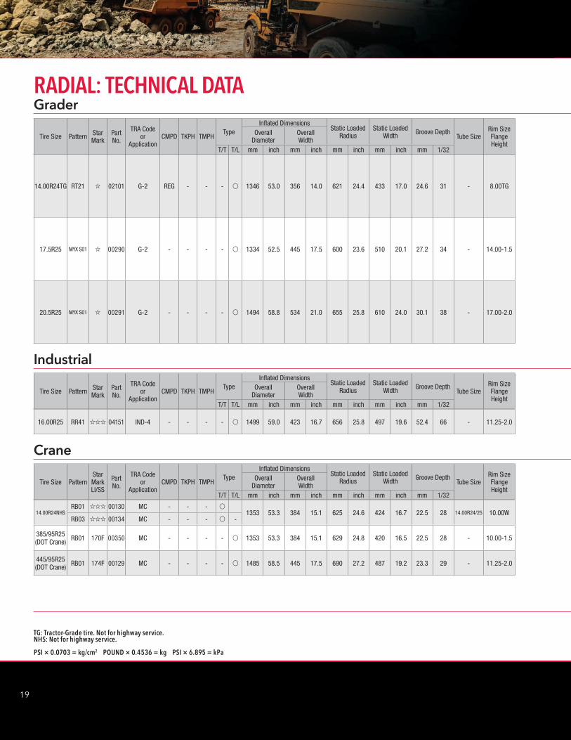
14.00R24NHSRB01 ;;; 00130 MC - - - v
1353 53.3 384 15.1 625 24.6 424 16.7 22.5 28 14.00R24/25 10.00WRB03 ;;; 00134 MC - - - v -
385/95R25(DOT Crane) RB01 170F 00350 MC - - - - v 1353 53.3 384 15.1 629 24.8 420 16.5 22.5 28 - 10.00-1.5
445/95R25(DOT Crane) RB01 174F 00129 MC - - - - v 1485 58.5 445 17.5 690 27.2 487 19.2 23.3 29 - 11.25-2.0
Tire Size PatternStar MarkLI/SS
Part No.
TRA Code or
ApplicationCMPD TKPH TMPH
TypeInflated Dimensions
Static Loaded Radius
Static Loaded Width Groove Depth
Tube SizeRim Size Flange Height
Overall Diameter
Overall Width
T/T T/L mm inch mm inch mm inch mm inch mm 1/32
Crane
16.00R25 RR41 ;;; 04151 IND-4 - - - - v 1499 59.0 423 16.7 656 25.8 497 19.6 52.4 66 - 11.25-2.0
Tire Size Pattern Star Mark
Part No.
TRA Code or
ApplicationCMPD TKPH TMPH
TypeInflated Dimensions
Static Loaded Radius
Static Loaded Width Groove Depth
Tube SizeRim Size Flange Height
Overall Diameter
Overall Width
T/T T/L mm inch mm inch mm inch mm inch mm 1/32
14.00R24TG RT21 ; 02101 G-2 REG - - - v 1346 53.0 356 14.0 621 24.4 433 17.0 24.6 31 - 8.00TG
17.5R25 MYX S01 ; 00290 G-2 - - - - v 1334 52.5 445 17.5 600 23.6 510 20.1 27.2 34 - 14.00-1.5
20.5R25 MYX S01 ; 00291 G-2 - - - - v 1494 58.8 534 21.0 655 25.8 610 24.0 30.1 38 - 17.00-2.0
Tire Size Pattern Star Mark
Part No.
TRA Code or
ApplicationCMPD TKPH TMPH
TypeInflated Dimensions
Static Loaded Radius
Static Loaded Width Groove Depth
Tube SizeRim Size Flange Height
Overall Diameter
Overall Width
T/T T/L mm inch mm inch mm inch mm inch mm 1/32
Industrial
GraderRADIAL: TECHNICAL DATA
2
20
YOKOHAMA OFF-THE-ROAD TIRES
Type T/T: Tube Type T/L: Tubeless Type CP: Cut Protected Specification Code REG: Regular HR: Heat Resistant CP-S: Cut Protected -S CPUG: Cut Protected for Underground
14.00R24NHSRB01 900 Kg. 16300 13200 11700 10100 - 6800 6500 *** 6200
RB03 130 lbs 35900 29100 25800 22300 - 15000 14300 13700
385/95R25(DOT Crane) RB01
900 Kg. 15000 - 12600 10800 7500 6900 - 6700 6600 6300 6000(170F) 5600 5100
130 lbs 33100 - 27800 23800 16500 15200 - 14800 14600 13900 13200 12300 11200
445/95R25(DOT Crane) RB01
900 Kg. 16800 - 14100 12100 8400 7700 - 7500 7400 7000 6700(174F) 6300 5700
130 lbs 37000 - 31100 26700 18500 17000 - 16500 16300 15400 14800 13900 12600
Tire Size PatternIP Tire Load Limits at Various Speeds
kPa km/h Static Creep 4 10 30 40 45 50 60 70 80 90 100PSI mph Static Creep 2.5 5 20 25 28 30 35 43 50 55 62
16.00R25 RR411000 Kg 22300 19800 18000 16700 16100 15700 15500
145 lbs 49200 43700 39700 36800 35500 34600 34200
Tire Size PatternIP Tire Load Limits at Various Speeds
For Smooth Floors and Runways UsekPa km/h 0 km/h Creep 4 10 15 20 25PSI mph Static Creep 2.5 5 10 12 15
14.00R24TG RT21
Grader
4025
SM *
kPa 200 225 250 275 300 325 350 375
psi 29 33 36 40 44 47 51 54
kg 2240 2430 2650 2800 3000 3250 3350 3650
lbs 4940 5360 5840 6150 6600 7150 7400 8050
17.5R25 MYX S01
Grader
4025
SM *
kPa 200 225 250 275 300
psi 29 33 36 40 44
kg 2650 2900 3075 3350 3650
lbs 5840 6400 6800 7400 8050
20.5R25 MYX S01
Grader
4025
SM *
kPa 200 225 250 275 300
psi 29 33 36 40 44
kg 3450 3875 4125 4375 4625
lbs 7600 8550 9100 9650 10200
Tire Size Pattern
ApplicationMax Speed
km/hmph
Tire Load Limits at Various Cold Inflation Pressures
21
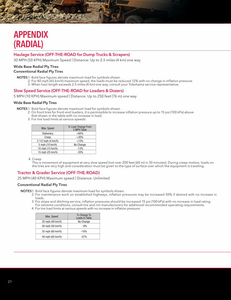
Haulage Service (OFF-THE-ROAD for Dump Trucks & Scrapers) 30 MPH (50 KPH) Maximum Speed | Distance: Up to 2.5 miles (4 km) one way
Slow Speed Service (OFF-THE-ROAD for Loaders & Dozers) 5 MPH (10 KPH) Maximum speed | Distance: Up to 250 feet (76 m) one way
Wide Base Radial Ply TiresConventional Radial Ply Tires
Wide Base Radial Ply Tires
NOTES 1. Bold face figures denote maximum load for symbols shown. 2. For 40 mph (65 km/h) maximum speed, the loads must be reduced 12% with no change in inflation pressure. 3. When haul length exceeds 2.5 miles (4 km) one way, consult your Yokohama service representative.
NOTES 1. Bold face figures denote maximum load for symbols shown. 2. On front tires for front-end loaders, it is permissible to increase inflation pressure up to 15 psi (100 kPa) above
that shown in the table with no increase in load. 3. For tire load limits at various speeds:
Max. Speed % Load Change From 5 MPH Table
Stationary +60%Creep +30%
2 1/2 mph (4 km/h) +15%5 mph (10 km/h) No Change
10 mph (15 km/h) -13%15 mph (25 km/h) -20%
4. Creep This is movement of equipment at very slow speed (not over 200 feet (60 m) in 30 minutes). During creep motion, loads on the tires are very high and consideration must be given to the type of surface over which the equipment is traveling.
Tractor & Grader Service (OFF-THE-ROAD)25 MPH (40 KPH) Maximum speed | Distance: Unlimited
NOTES 1. Bold face figures denote maximum load for symbols shown. 2. For maintenance work on established highways, inflation pressures may be increased 50% if desired with no increase in
loads. 3. For slope and ditching service, inflation pressures should be increased 15 psi (100 kPa) with no increase in load rating. For extreme conditions, consult tire and rim manufacturers for additional recommended operating requirements. 4. For tire load limits at various speeds with no increase in inflation pressure:
Max. Speed % Change To Loads In Table
25 mph (40 km/h) No Change
30 mph (50 km/h) -9%
35 mph (60 km/h) -18%
40 mph (65 km/h) -27%
Conventional Radial Ply Tires
APPENDIX (RADIAL)
2
22
YOKOHAMA OFF-THE-ROAD TIRES
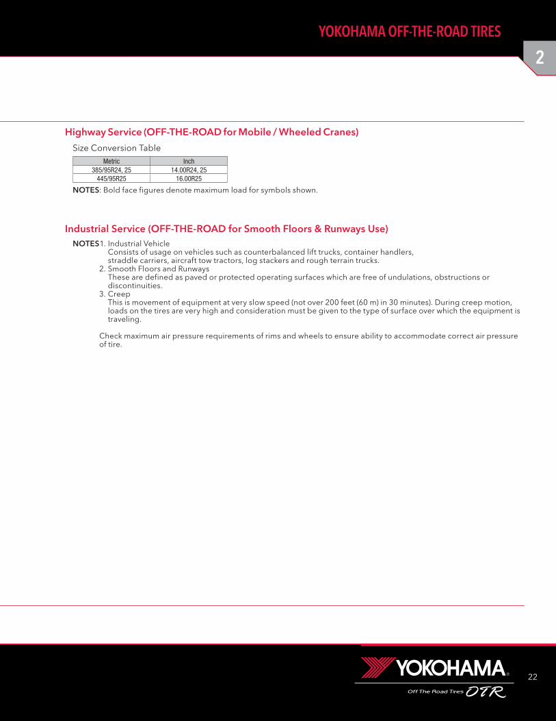
Highway Service (OFF-THE-ROAD for Mobile / Wheeled Cranes)
Metric Inch385/95R24, 25 14.00R24, 25
445/95R25 16.00R25
Size Conversion Table
NOTES 1. Industrial Vehicle Consists of usage on vehicles such as counterbalanced lift trucks, container handlers, straddle carriers, aircraft tow tractors, log stackers and rough terrain trucks.
2. Smooth Floors and Runways These are defined as paved or protected operating surfaces which are free of undulations, obstructions or discontinuities.
3. Creep This is movement of equipment at very slow speed (not over 200 feet (60 m) in 30 minutes). During creep motion, loads on the tires are very high and consideration must be given to the type of surface over which the equipment is traveling.
Check maximum air pressure requirements of rims and wheels to ensure ability to accommodate correct air pressure of tire.
Industrial Service (OFF-THE-ROAD for Smooth Floors & Runways Use)
NOTES: Bold face figures denote maximum load for symbols shown.
23
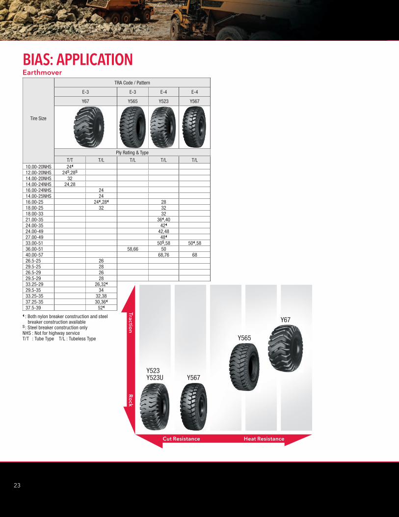
BIAS: APPLICATION
Tire Size
TRA Code / Pattern
E-3 E-3 E-4 E-4
Y67 Y565 Y523 Y567
Ply Rating & Type
T/T T/L T/L T/L T/L10.00-20NHS 24B
12.00-20NHS 24s,28s14.00-20NHS 3214.00-24NHS 24,2816.00-24NHS 2414.00-25NHS 2416.00-25 24B,28B 2818.00-25 32 3218.00-33 3221.00-35 36B,4024.00-35 42B
24.00-49 42,4827.00-49 48B
33.00-51 50s,58 50B,5836.00-51 58,66 5040.00-57 68,76 6826.5-25 2629.5-25 2826.5-29 2629.5-29 2833.25-29 26,32B
29.5-35 3433.25-35 32,3837.25-35 30,36B
37.5-39 52B
B : Both nylon breaker construction and steel breaker construction availables : Steel breaker construction onlyNHS : Not for highway serviceT/T : Tube Type T/L : Tubeless Type
Earthmover
Cut Resistance Heat Resistance
Traction
Ro
ck
Y523Y523U Y567
Y565
Y67
2
24
YOKOHAMA OFF-THE-ROAD TIRES
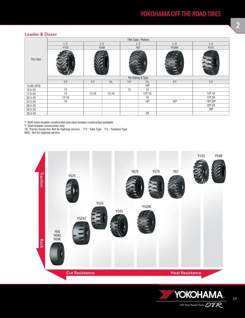
Tire Size
TRA Code / PatternL-2 L-2 L-3 L-3 L-3
Y103 Y548 Y67 Y526K Y575
Ply Rating & TypeT/T T/T T/L T/T T/L T/T T/T
13.00-24TG 16s
15.5-25 12 12 1217.5-25 12 12,16 12,16 12B,16 12B,1620.5-25 12,16 16 12B,2023.5-25 16 16B 16B 16B,20B
26.5-25 20B,2429.5-25 28B
29.5-29 28
B : Both nylon breaker construction and steel breaker construction availables : Steel breaker construction onlyTG: Tractor-Grade tire. Not for highway service. T/T : Tube Type T/L : Tubeless TypeNHS : Not for highway service
Loader & Dozer
Cut Resistance Heat Resistance
Traction
Ro
ck
Y69Y69UY69K
Y524Z
Y524
Y525Y67
Y545Y526K
Y575Y67E
Y103 Y548
25
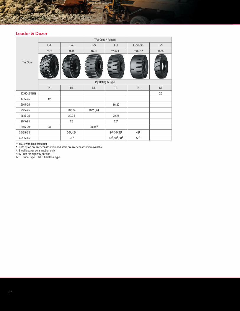
Tire Size
TRA Code / Pattern
L-4 L-4 L-5 L-5 L-5/L-5S L-5
Y67E Y545 Y524 **Y524 **Y524Z Y525
Ply Rating & Type
T/L T/L T/L T/L T/L T/T
12.00-24NHS 20
17.5-25 12
20.5-25 16,20
23.5-25 20B,24 16,20,24
26.5-25 20,24 20,24
29.5-25 28 28B
29.5-29 28 28,34s
35/65-33 30s,42s 24s,30s,42s 42s
45/65-45 58s 38s,50s,58s 58s
** Y524 with side protectorB : Both nylon breaker construction and steel breaker construction availables : Steel breaker construction onlyNHS : Not for highway serviceT/T : Tube Type T/L : Tubeless Type
Loader & Dozer
2
26
YOKOHAMA OFF-THE-ROAD TIRES
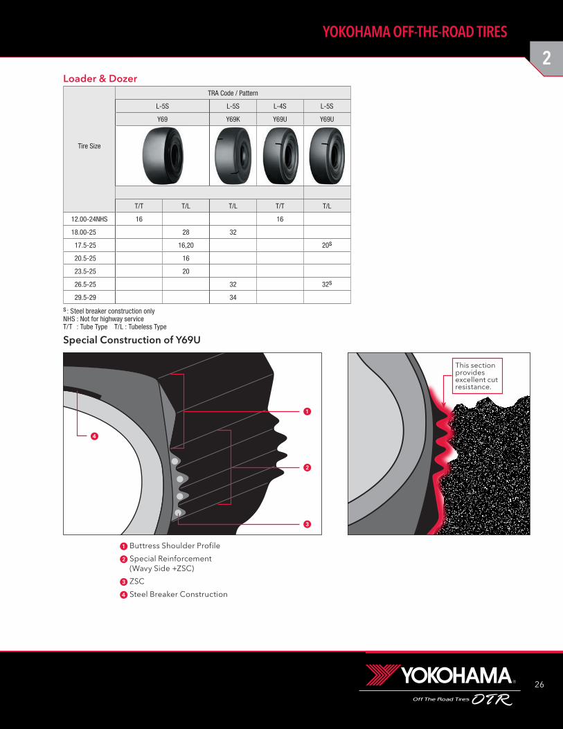
s : Steel breaker construction onlyNHS : Not for highway serviceT/T : Tube Type T/L : Tubeless Type
Tire Size
TRA Code / Pattern
L-5S L-5S L-4S L-5S
Y69 Y69K Y69U Y69U
T/T T/L T/L T/T T/L
12.00-24NHS 16 16
18.00-25 28 32
17.5-25 16,20 20s
20.5-25 16
23.5-25 20
26.5-25 32 32s
29.5-29 34
Loader & Dozer
This sectionprovidesexcellent cutresistance.
Special Construction of Y69U
1 Buttress Shoulder Profile
2 Special Reinforcement (Wavy Side +ZSC)
3 ZSC
4 Steel Breaker Construction
1
2
3
4
27
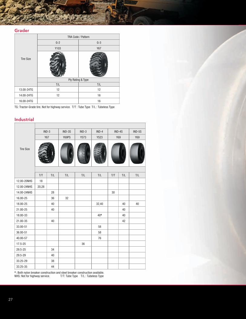
Tire Size
TRA Code / Pattern
G-2 G-3
Y103 Y67
Ply Rating & Type
T/L T/L
13.00-24TG 12 12
14.00-24TG 12 16
16.00-24TG 16
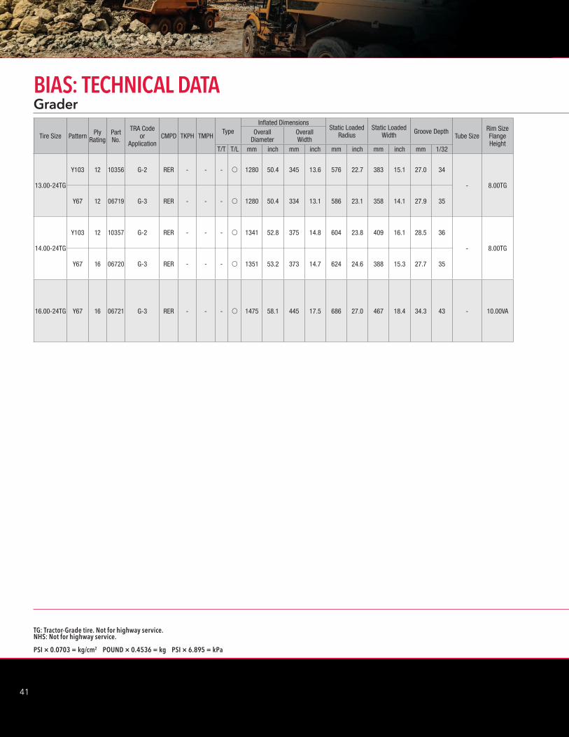
TG: Tractor-Grade tire. Not for highway service. T/T : Tube Type T/L : Tubeless Type
Grader
B : Both nylon breaker construction and steel breaker construction available.NHS: Not for highway service. T/T: Tube Type T/L : Tubeless Type
Tire Size
IND-3 IND-3S IND-3 IND-4 IND-4S IND-5S
Y67 Y69PS Y573 Y523 Y69 Y69
T/T T/L T/L T/L T/L T/T T/L T/L
12.00-20NHS 18
12.00-24NHS 20,28
14.00-24NHS 28 30
16.00-25 36 32
18.00-25 40 32,40 40 40
21.00-25 40 40
18.00-33 40B 40
21.00-35 40 42
33.00-51 58
36.00-51 58
40.00-57 76
17.5-25 36
29.5-25 34
29.5-29 40
33.25-29 38
33.25-35 44
Industrial
2
28
YOKOHAMA OFF-THE-ROAD TIRES

29
TG: Tractor-Grade tire. Not for highway service.NHS: Not for highway service.
PSI × 0.0703 = kg/cm2 POUND × 0.4536 = kg PSI × 6.895 = kPa
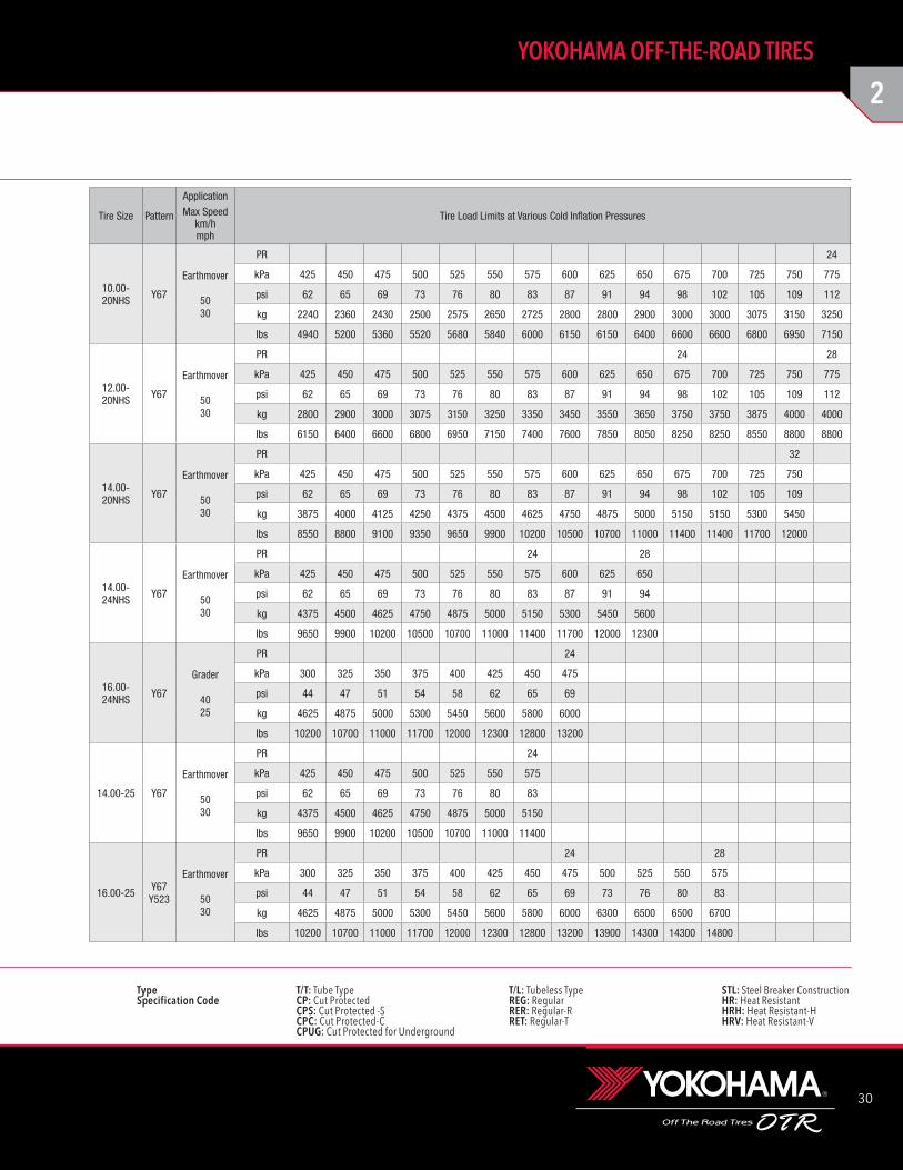
10.00-20NHS Y67 24 16757 E-3 RER - - v - 1060 41.7 280 11.0 498 19.6 295 11.6 20.4 26 10.00-20 8.50V
12.00-20NHS
Y67 24 16759 E-3 CP - - v -
1135 44.7 322 12.7 516 20.3 347 13.7 25.5 32 12.00-20 8.50V
Y67 28 16786 E-3 CP - - v -
14.00-20NHS Y67 32 16765 E-3 CP - - v - 1250 49.2 386 15.2 583 23.0 401 15.8 27.5 35 14.00-20 10.00WI
14.00-24NHS
Y67 24 06715 E-3 CPC 95 65 v -
1345 53.0 380 15.0 624 24.6 408 16.1 27.7 35 14.00-24/25 10.00W
Y67 28 06716 E-3 CPC 95 65 v -
16.00-24NHS Y67 24 06722 E-3 CPC 139 95 - v 1475 58.1 445 17.5 686 27.0 467 18.4 34.3 43 - 11.25-2.0
14.00-25 Y67 24 06708 E-3 RER 109 75 - v 1345 53.0 380 15.0 624 24.6 408 16.1 27.7 35 - 10.00-1.5
16.00-25
Y67 24 06709 E-3 CPC 124 85 - v 1475 58.1 445 17.5 686 27.0 467 18.4 34.3 43
- 11.25-2.0Y67 28 06710 E-3 CPC 124 85 - v - - - - - - - - - -
Y523 28 02326 E-4 CPC 102 70 - v 1540 60.6 443 17.4 724 28.5 467 18.4 59.3 75
Tire Size Pattern Ply Rating
Part No.
TRA Code or
ApplicationCMPD TKPH TMPH
TypeInflated Dimensions
Static Loaded Radius
Static Loaded Width Groove Depth
Tube SizeRim Size Flange Height
Overall Diameter
Overall Width
T/T T/L mm inch mm inch mm inch mm inch mm 1/32
EarthmoverBIAS: TECHNICAL DATA
2
30
YOKOHAMA OFF-THE-ROAD TIRES
Type T/T: Tube Type T/L: Tubeless Type STL: Steel Breaker ConstructionSpecification Code CP: Cut Protected REG: Regular HR: Heat Resistant CPS: Cut Protected -S RER: Regular-R HRH: Heat Resistant-H CPC: Cut Protected-C RET: Regular-T HRV: Heat Resistant-V CPUG: Cut Protected for Underground
10.00-20NHS Y67
Earthmover
5030
PR 24
kPa 425 450 475 500 525 550 575 600 625 650 675 700 725 750 775
psi 62 65 69 73 76 80 83 87 91 94 98 102 105 109 112
kg 2240 2360 2430 2500 2575 2650 2725 2800 2800 2900 3000 3000 3075 3150 3250
lbs 4940 5200 5360 5520 5680 5840 6000 6150 6150 6400 6600 6600 6800 6950 7150
12.00-20NHS Y67
Earthmover
5030
PR 24 28
kPa 425 450 475 500 525 550 575 600 625 650 675 700 725 750 775
psi 62 65 69 73 76 80 83 87 91 94 98 102 105 109 112
kg 2800 2900 3000 3075 3150 3250 3350 3450 3550 3650 3750 3750 3875 4000 4000
lbs 6150 6400 6600 6800 6950 7150 7400 7600 7850 8050 8250 8250 8550 8800 8800
14.00-20NHS Y67
Earthmover
5030
PR 32
kPa 425 450 475 500 525 550 575 600 625 650 675 700 725 750
psi 62 65 69 73 76 80 83 87 91 94 98 102 105 109
kg 3875 4000 4125 4250 4375 4500 4625 4750 4875 5000 5150 5150 5300 5450
lbs 8550 8800 9100 9350 9650 9900 10200 10500 10700 11000 11400 11400 11700 12000
14.00-24NHS Y67
Earthmover
5030
PR 24 28
kPa 425 450 475 500 525 550 575 600 625 650
psi 62 65 69 73 76 80 83 87 91 94
kg 4375 4500 4625 4750 4875 5000 5150 5300 5450 5600
lbs 9650 9900 10200 10500 10700 11000 11400 11700 12000 12300
16.00-24NHS Y67
Grader
4025
PR 24
kPa 300 325 350 375 400 425 450 475
psi 44 47 51 54 58 62 65 69
kg 4625 4875 5000 5300 5450 5600 5800 6000
lbs 10200 10700 11000 11700 12000 12300 12800 13200
14.00-25 Y67
Earthmover
5030
PR 24
kPa 425 450 475 500 525 550 575
psi 62 65 69 73 76 80 83
kg 4375 4500 4625 4750 4875 5000 5150
lbs 9650 9900 10200 10500 10700 11000 11400
16.00-25 Y67Y523
Earthmover
5030
PR 24 28
kPa 300 325 350 375 400 425 450 475 500 525 550 575
psi 44 47 51 54 58 62 65 69 73 76 80 83
kg 4625 4875 5000 5300 5450 5600 5800 6000 6300 6500 6500 6700
lbs 10200 10700 11000 11700 12000 12300 12800 13200 13900 14300 14300 14800
Tire Size Pattern
ApplicationMax Speed
km/hmph
Tire Load Limits at Various Cold Inflation Pressures
31
TG: Tractor-Grade tire. Not for highway service.NHS: Not for highway service.
PSI × 0.0703 = kg/cm2 POUND × 0.4536 = kg PSI × 6.895 = kPa
Tire Size Pattern Ply Rating
Part No.
TRA Code or
ApplicationCMPD TKPH TMPH
TypeInflated Dimensions
Static Loaded Radius
Static Loaded Width Groove Depth
Tube SizeRim Size Flange Height
Overall Diameter
Overall Width
T/T T/L mm inch mm inch mm inch mm inch mm 1/32
EarthmoverBIAS: TECHNICAL DATA
18.00-25
Y67 32 06732 E-3 CPC 160 110 - v 1599 63.0 520 20.5 734 28.9 540 21.3 38.5 49
- 13.00-2.5
Y523 32 52304 E-4 CPC 139 95 - v 1652 65.0 517 20.4 772 30.4 541 21.3 61.3 77
18.00-33
Y523 32 52315 E-4 CPC 153 105 - v
1800 70.9 520 20.5 840 33.1 554 21.8 41.1 52 - 13.00-2.5
Y523 32 52318 E-4 RER 125 102 - v
21.00-35
Y523 36 02302 E-4 CPC 190 130 - v
2045 80.5 590 23.2 951 37.4 623 24.5 63.2 80 - 15.00-3.0Y523 36 02336 E-4 CPC/STL 133 91 - v
Y523 40 52320 E-4 RER 219 150 - v
24.00-35
Y523 42 02320 E-4 CPC 226 155 - v
2175 85.6 687 27.0 990 39.0 710 28.0 64.6 81 - 17.00-3.5Y523 42 52322 E-4 RER 263 180 - v
Y523 42 52330 E-4 CPC/STL 158 109 - v
24.00-49 Y523 42 52339 E-4 CPC 277 190 - v 2529 99.6 655 25.8 1184 46.6 697 27.4 64.6 81 - 17.00-3.5
27.00-49
Y523 48 52341 E-4 CPC 336 230 - v
2659 105.5 748 29.4 1245 49.0 791 31.1 71.3 90 - 19.50-4.0Y523 48 52373 E-4 RER 387 265 - v
Y523 48 02328 E-4 CPC/STL 235 161 - v
33.00-51
Y523 50 52329 E-4 CPC/STL 361 248 - v3039 119.6 927 36.5 1404 55.3 985 38.8 82.7 104
- 24.00-5.0
Y523 58 02329 E-4 HRV 642 440 - v
Y567 50 56754 E-4 CPC 516 354 - v
3039 119.6 927 36.5 1404 55.3 985 38.8 82.7 104Y567 50 56755 E-4 RER 613 420 - v
Y567 58 56750 E-4 CPC 516 354 - v
Y567 58 56752 E-4 RET 664 455 - v

2
32
YOKOHAMA OFF-THE-ROAD TIRES
Type T/T: Tube Type T/L: Tubeless Type STL: Steel Breaker ConstructionSpecification Code CP: Cut Protected REG: Regular HR: Heat Resistant CPS: Cut Protected -S RER: Regular-R HRH: Heat Resistant-H CPC: Cut Protected-C RET: Regular-T HRV: Heat Resistant-V CPUG: Cut Protected for Underground
18.00-25 Y67Y523
Earthmover
5030
PR 28 32
kPa 300 325 350 375 400 425 450 475 500 525 550 575
psi 44 47 51 54 58 62 65 69 73 76 80 83
kg 6000 6300 6500 6900 7100 7300 7500 7750 8000 8250 8500 8750
lbs 13200 13900 14300 15200 15700 16100 16500 17100 17600 18200 18700 19300
18.00-33 Y523
Earthmover
5030
PR 28 32
kPa 300 325 350 375 400 425 450 475 500 525 550 575
psi 44 47 51 54 58 62 65 69 73 76 80 83
kg 6900 7300 7500 8000 8250 8500 8750 9000 9250 9500 10000 10300
lbs 15200 16100 16500 17600 18200 18700 19300 19800 20400 20900 22000 22700
21.00-35 Y523
Earthmover
5030
PR 36 40
kPa 300 325 350 375 400 425 450 475 500 525 550 575 600 625
psi 44 47 51 54 58 62 65 69 73 76 80 83 87 91
kg 9250 9500 10000 10300 10900 11200 11500 11800 12150 12500 12850 13200 13600 14000
lbs 20400 20900 22000 22700 24000 24700 25400 26000 26800 27600 28300 29100 30000 30900
24.00-35 Y523
Earthmover
5030
PR 42
kPa 300 325 350 375 400 425 450 475 500 525 550 575
psi 44 47 51 54 58 62 65 69 73 76 80 83
kg 11800 12150 12850 13200 14000 14500 15000 15500 15500 16000 16500 17000
lbs 26000 26800 28300 29100 30900 32000 33100 34200 34200 35300 36400 37500
24.00-49 Y523
Earthmover
5030
PR 42
kPa 300 325 350 375 400 425 450 475 500 525 550 575
psi 44 47 51 54 58 62 65 69 73 76 80 83
kg 14000 14500 15500 16000 16500 17000 17500 18500 19000 19500 20000 20600
lbs 30900 32000 34200 35300 36400 37500 38600 40800 41900 43000 44100 45400
27.00-49 Y523
Earthmover
5030
PR 48
kPa 300 325 350 375 400 425 450 475 500 525 550 575
psi 44 47 51 54 58 62 65 69 73 76 80 83
kg 17000 18000 19000 19500 20600 21200 21800 22400 23000 23600 24300 25000
lbs 37500 39700 41900 43000 45400 46700 48100 49400 50700 52000 53600 55100
33.00-51 Y523Y567
Earthmover
5030
PR 50 58
kPa 300 325 350 375 400 425 450 475 500 525 550 575
psi 44 47 51 54 58 62 65 69 73 76 80 83
kg 24300 25750 27250 28000 29000 30000 31500 32500 33500 34500 35500 35500
lbs 53600 56800 60000 61500 64000 66000 69500 71500 74000 76000 78500 78500
Tire Size Pattern
ApplicationMax Speed
km/hmph
Tire Load Limits at Various Cold Inflation Pressures
33
TG: Tractor-Grade tire. Not for highway service.NHS: Not for highway service.
PSI × 0.0703 = kg/cm2 POUND × 0.4536 = kg PSI × 6.895 = kPa
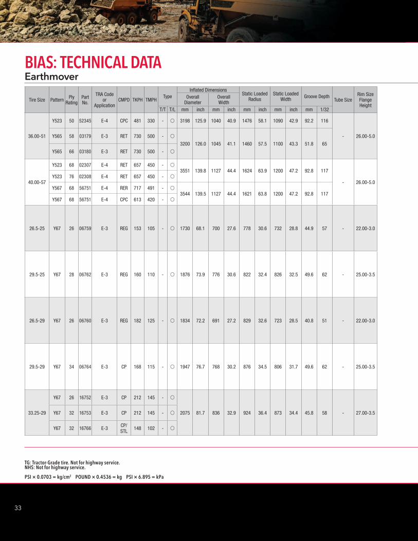
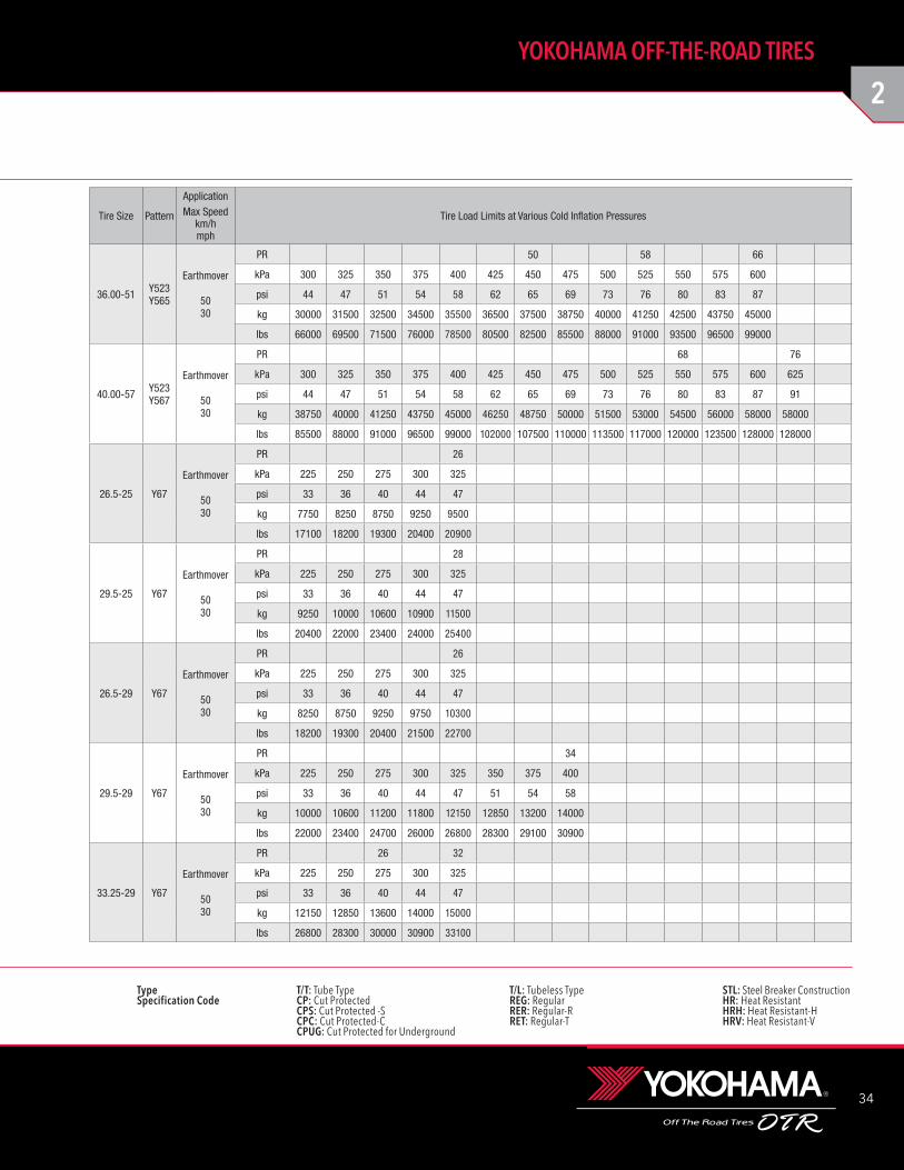
36.00-51
Y523 50 52345 E-4 CPC 481 330 - v 3198 125.9 1040 40.9 1476 58.1 1090 42.9 92.2 116
- 26.00-5.0Y565 58 03179 E-3 RET 730 500 - v
3200 126.0 1045 41.1 1460 57.5 1100 43.3 51.8 65
Y565 66 03180 E-3 RET 730 500 - v
40.00-57
Y523 68 02307 E-4 RET 657 450 - v3551 139.8 1127 44.4 1624 63.9 1200 47.2 92.8 117
- 26.00-5.0Y523 76 02308 E-4 RET 657 450 - v
Y567 68 56751 E-4 RER 717 491 - v3544 139.5 1127 44.4 1621 63.8 1200 47.2 92.8 117
Y567 68 56751 E-4 CPC 613 420 - v
26.5-25 Y67 26 06759 E-3 REG 153 105 - v 1730 68.1 700 27.6 778 30.6 732 28.8 44.9 57 - 22.00-3.0
29.5-25 Y67 28 06762 E-3 REG 160 110 - v 1876 73.9 776 30.6 822 32.4 826 32.5 49.6 62 - 25.00-3.5
26.5-29 Y67 26 06760 E-3 REG 182 125 - v 1834 72.2 691 27.2 829 32.6 723 28.5 40.8 51 - 22.00-3.0
29.5-29 Y67 34 06764 E-3 CP 168 115 - v 1947 76.7 768 30.2 876 34.5 806 31.7 49.6 62 - 25.00-3.5
33.25-29
Y67 26 16752 E-3 CP 212 145 - v
2075 81.7 836 32.9 924 36.4 873 34.4 45.8 58 - 27.00-3.5Y67 32 16753 E-3 CP 212 145 - v
Y67 32 16766 E-3 CP/STL 148 102 - v
Tire Size Pattern PlyRating
Part No.
TRA Code or
ApplicationCMPD TKPH TMPH
TypeInflated Dimensions
Static Loaded Radius
Static Loaded Width Groove Depth
Tube SizeRim Size Flange Height
Overall Diameter
Overall Width
T/T T/L mm inch mm inch mm inch mm inch mm 1/32
EarthmoverBIAS: TECHNICAL DATA
2
34
YOKOHAMA OFF-THE-ROAD TIRES
Type T/T: Tube Type T/L: Tubeless Type STL: Steel Breaker ConstructionSpecification Code CP: Cut Protected REG: Regular HR: Heat Resistant CPS: Cut Protected -S RER: Regular-R HRH: Heat Resistant-H CPC: Cut Protected-C RET: Regular-T HRV: Heat Resistant-V CPUG: Cut Protected for Underground
36.00-51 Y523Y565
Earthmover
5030
PR 50 58 66
kPa 300 325 350 375 400 425 450 475 500 525 550 575 600
psi 44 47 51 54 58 62 65 69 73 76 80 83 87
kg 30000 31500 32500 34500 35500 36500 37500 38750 40000 41250 42500 43750 45000
lbs 66000 69500 71500 76000 78500 80500 82500 85500 88000 91000 93500 96500 99000
40.00-57 Y523Y567
Earthmover
5030
PR 68 76
kPa 300 325 350 375 400 425 450 475 500 525 550 575 600 625
psi 44 47 51 54 58 62 65 69 73 76 80 83 87 91
kg 38750 40000 41250 43750 45000 46250 48750 50000 51500 53000 54500 56000 58000 58000
lbs 85500 88000 91000 96500 99000 102000 107500 110000 113500 117000 120000 123500 128000 128000
26.5-25 Y67
Earthmover
5030
PR 26
kPa 225 250 275 300 325
psi 33 36 40 44 47
kg 7750 8250 8750 9250 9500
lbs 17100 18200 19300 20400 20900
29.5-25 Y67
Earthmover
5030
PR 28
kPa 225 250 275 300 325
psi 33 36 40 44 47
kg 9250 10000 10600 10900 11500
lbs 20400 22000 23400 24000 25400
26.5-29 Y67
Earthmover
5030
PR 26
kPa 225 250 275 300 325
psi 33 36 40 44 47
kg 8250 8750 9250 9750 10300
lbs 18200 19300 20400 21500 22700
29.5-29 Y67
Earthmover
5030
PR 34
kPa 225 250 275 300 325 350 375 400
psi 33 36 40 44 47 51 54 58
kg 10000 10600 11200 11800 12150 12850 13200 14000
lbs 22000 23400 24700 26000 26800 28300 29100 30900
33.25-29 Y67
Earthmover
5030
PR 26 32
kPa 225 250 275 300 325
psi 33 36 40 44 47
kg 12150 12850 13600 14000 15000
lbs 26800 28300 30000 30900 33100
Tire Size Pattern
ApplicationMax Speed
km/hmph
Tire Load Limits at Various Cold Inflation Pressures

35
TG: Tractor-Grade tire. Not for highway service.NHS: Not for highway service.
PSI × 0.0703 = kg/cm2 POUND × 0.4536 = kg PSI × 6.895 = kPa
EarthmoverBIAS: TECHNICAL DATA
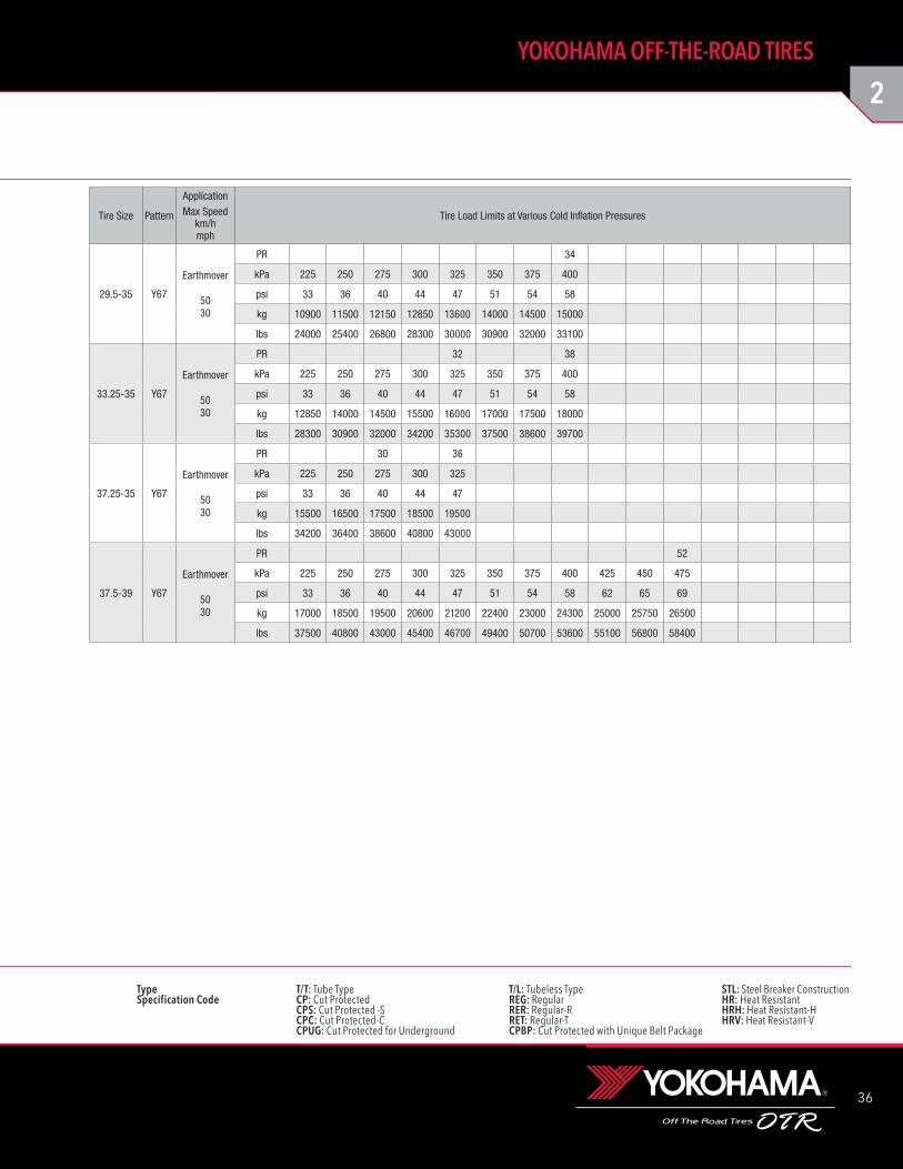
29.5-35 Y67 34 06766 E-3 REG 248 170 - v 2120 83.5 776 30.6 965 38.0 819 32.2 39.5 50 - 25.00-3.5
33.25-35
Y67 32 16711 E-3 CP 226 155 - v
2248 88.5 853 33.6 1003 39.5 898 35.4 47.1 59 - 27.00-3.5
Y67 38 06770 E-3 REG 263 180 v
37.25-35
Y67 30 16701 E-3 CP 277 190 - v
2390 94.1 960 37.8 1060 41.7 1010 39.8 50.6 64 - 31.00-4.0Y67 30 16751 E-3 CPBP 277 190 - v
Y67 36 16715 E-3 CP 277 190 - v
Y67 36 16714 E-3 CP/STL 194 133 - v
37.5-39
Y67 52 16712 E-3 REG 385 264
- v 2556 100.6 949 37.4 1137 44.8 1015 40.0 53.8 68 - 32.00-4.5
Y67 52 16750 E-3 CP/STL 225 154
Tire Size Pattern PlyRating
Part No.
TRA Code or
ApplicationCMPD TKPH TMPH
TypeInflated Dimensions
Static Loaded Radius
Static Loaded Width Groove Depth
Tube SizeRim Size Flange Height
Overall Diameter
Overall Width
T/T T/L mm inch mm inch mm inch mm inch mm 1/32
2
36
YOKOHAMA OFF-THE-ROAD TIRES
Type T/T: Tube Type T/L: Tubeless Type STL: Steel Breaker ConstructionSpecification Code CP: Cut Protected REG: Regular HR: Heat Resistant CPS: Cut Protected -S RER: Regular-R HRH: Heat Resistant-H CPC: Cut Protected-C RET: Regular-T HRV: Heat Resistant-V CPUG: Cut Protected for Underground CPBP: Cut Protected with Unique Belt Package
29.5-35 Y67
Earthmover
5030
PR 34
kPa 225 250 275 300 325 350 375 400
psi 33 36 40 44 47 51 54 58
kg 10900 11500 12150 12850 13600 14000 14500 15000
lbs 24000 25400 26800 28300 30000 30900 32000 33100
33.25-35 Y67
Earthmover
5030
PR 32 38
kPa 225 250 275 300 325 350 375 400
psi 33 36 40 44 47 51 54 58
kg 12850 14000 14500 15500 16000 17000 17500 18000
lbs 28300 30900 32000 34200 35300 37500 38600 39700
37.25-35 Y67
Earthmover
5030
PR 30 36
kPa 225 250 275 300 325
psi 33 36 40 44 47
kg 15500 16500 17500 18500 19500
lbs 34200 36400 38600 40800 43000
37.5-39 Y67
Earthmover
5030
PR 52
kPa 225 250 275 300 325 350 375 400 425 450 475
psi 33 36 40 44 47 51 54 58 62 65 69
kg 17000 18500 19500 20600 21200 22400 23000 24300 25000 25750 26500
lbs 37500 40800 43000 45400 46700 49400 50700 53600 55100 56800 58400
Tire Size Pattern
ApplicationMax Speed
km/hmph
Tire Load Limits at Various Cold Inflation Pressures
37
TG: Tractor-Grade tire. Not for highway service.NHS: Not for highway service.
PSI × 0.0703 = kg/cm2 POUND × 0.4536 = kg PSI × 6.895 = kPa
Tire Size Pattern PlyRating
Part No.
TRA Code or
ApplicationCMPD TKPH TMPH
TypeInflated Dimensions
Static Loaded Radius
Static Loaded Width Groove Depth
Tube SizeRim Size Flange Height
Overall Diameter
Overall Width
T/T T/L mm inch mm inch mm inch mm inch mm 1/32
12.00-24 NHS
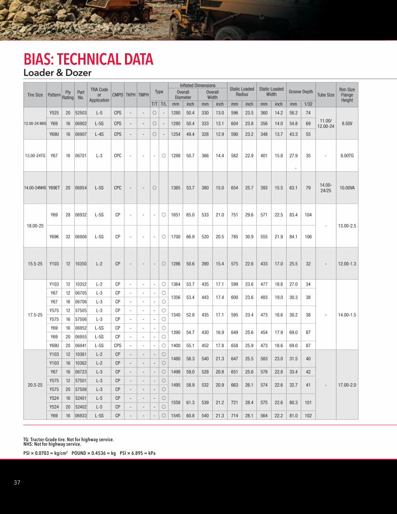
Y525 20 52503 L-5 CPS - - v - 1280 50.4 330 13.0 596 23.5 360 14.2 58.2 74
11.00/ 12.00-24 8.50VY69 16 06902 L-5S CPS - - v - 1280 50.4 333 13.1 604 23.8 356 14.0 54.8 69
Y69U 16 06907 L-4S CPS - - v - 1254 49.4 328 12.9 590 23.2 348 13.7 43.3 55
13.00-24TG Y67 16 06701 L-3 CPC - - - v 1288 50.7 366 14.4 582 22.9 401 15.8 27.9 35 - 8.00TG
14.00-24NHS Y69ET 20 06954 L-5S CPC - - v - 1365 53.7 380 15.0 654 25.7 393 15.5 63.1 79 14.00-24/25 10.00VA
18.00-25
Y69 28 06932 L-5S CP - - - v 1651 65.0 533 21.0 751 29.6 571 22.5 83.4 104
- 13.00-2.5
Y69K 32 06906 L-5S CP - - - v 1700 66.9 520 20.5 785 30.9 555 21.9 84.1 106
15.5-25 Y103 12 10350 L-2 CP - - - v 1286 50.6 390 15.4 575 22.6 433 17.0 25.5 32 - 12.00-1.3
17.5-25
Y103 12 10352 L-2 CP - - - v 1364 53.7 435 17.1 599 23.6 477 18.8 27.0 34
- 14.00-1.5
Y67 12 06705 L-3 CP - - - v1356 53.4 443 17.4 600 23.6 483 19.0 30.3 38
Y67 16 06706 L-3 CP - - - v
Y575 12 57505 L-3 CP - - - v1340 52.8 435 17.1 595 23.4 473 18.6 30.2 38
Y575 16 57506 L-3 CP - - - v
Y69 16 06952 L-5S CP - - - v1390 54.7 430 16.9 649 25.6 454 17.9 69.0 87
Y69 20 06955 L-5S CP - - - v
Y69U 20 06941 L-5S CPS - - - v 1400 55.1 452 17.8 658 25.9 473 18.6 69.0 87
20.5-25
Y103 12 10361 L-2 CP - - - v1480 58.3 540 21.3 647 25.5 583 23.0 31.5 40
- 17.00-2.0
Y103 16 10362 L-2 CP - - - v
Y67 16 06723 L-3 CP - - - v 1498 59.0 528 20.8 651 25.6 578 22.8 33.4 42
Y575 12 57501 L-3 CP - - - v1495 58.9 532 20.9 663 26.1 574 22.6 32.7 41
Y575 20 57508 L-3 CP - - - v
Y524 16 52401 L-5 CP - - - v1558 61.3 539 21.2 721 28.4 575 22.6 80.3 101
Y524 20 52402 L-5 CP - - - v
Y69 16 06933 L-5S CP - - - v 1545 60.8 540 21.3 714 28.1 564 22.2 81.0 102
Loader & DozerBIAS: TECHNICAL DATA
-
2
38
YOKOHAMA OFF-THE-ROAD TIRES
Type T/T: Tube Type T/L: Tubeless Type STL: Steel Breaker ConstructionSpecification Code CP: Cut Protected REG: Regular HR: Heat Resistant CPS: Cut Protected -S RER: Regular-R HRH: Heat Resistant-H CPC: Cut Protected-C RET: Regular-T HRV: Heat Resistant-V CPUG: Cut Protected for Underground
Tire Size Pattern
ApplicationMax Speed
km/hmph
Tire Load Limits at Various Cold Inflation Pressures
12.00-24 NHSY525Y69
Y69U
Loader
105
PR 16 20kPa 600 625 650 675 700 725 750 775 800 825psi 87 91 94 98 102 105 109 112 116 120kg 5600 5800 6000 6150 6300 6300 6500 6700 6700 6900lbs 12300 12800 13200 13600 13900 13900 14300 14800 14800 15200
13.00-24TG Y67
Loader
105
PR 16kPa 400 425 450 475 500 525 550 575 600psi 58 62 65 69 73 76 80 83 87kg 5150 5450 5600 5800 6000 6150 6300 6500 6500lbs 11400 12000 12300 12800 13200 13600 13900 14300 14300
14.00-24NHS Y69ET
Loader
105
PR 20kPa 400 425 450 475 500 525 550 575 600 625 650 675 700psi 58 62 65 69 73 76 80 83 87 91 94 98 102kg 6150 6300 6500 6700 6900 7100 7300 7500 7750 8000 8250 8250 8500lbs 13600 13900 14300 14800 15200 15700 16100 16500 17100 17600 18200 18200 18700
18.00-25 Y69Y69K
Loader
105
PR 28 32
kPa 400 425 450 475 500 525 550 575 600 625 650 675 700 725 750
psi 58 62 65 69 73 76 80 83 87 91 94 98 102 105 109
kg 10300 10600 11200 11500 11800 12150 12500 12850 13200 13600 13600 14000 14500 14500 15000
lbs 22700 23400 24700 25400 26000 26800 27600 28300 29100 30000 30000 30900 32000 32000 33100
15.5-25 Y103
Loader
105
PR 12kPa 225 250 275 300 325 350 375 400psi 33 36 40 44 47 51 54 58kg 4000 4250 4500 4750 4875 5150 5300 5600lbs 8800 9350 9900 10500 10700 11400 11700 12300
17.5-25
Y103Y67Y575Y524Y69
Loader
105
PR 12 16 20
kPa 225 250 275 300 325 350 375 400 425 450 475 500 525 550 575
psi 33 36 40 44 47 51 54 58 62 65 69 73 76 80 83
kg 4750 5000 5300 5600 5800 6150 6300 6700 6900 7100 7300 7500 7750 8000 8250
lbs 10500 11000 11700 12300 12800 13600 13900 14800 15200 15700 16100 16500 17100 17600 18200
20.5-25
Y103Y67Y575Y524Y69
Loader
105
PR 12 16 20
kPa 225 250 275 300 325 350 375 400 425 450
psi 33 36 40 44 47 51 54 58 62 65
kg 6300 6700 7100 7500 7750 8250 8500 8750 9250 9500
lbs 13900 14800 15700 16500 17100 18200 18700 19300 20400 20900

39
TG: Tractor-Grade tire. Not for highway service.NHS: Not for highway service.
PSI × 0.0703 = kg/cm2 POUND × 0.4536 = kg PSI × 6.895 = kPa
Tire Size Pattern PlyRating
Part No.
TRA Code or
ApplicationCMPD TKPH TMPH
TypeInflated Dimensions
Static Loaded Radius
Static Loaded Width Groove Depth
Tube SizeRim Size Flange Height
Overall Diameter
Overall Width
T/T T/L mm inch mm inch mm inch mm inch mm 1/32
23.5-25
Y103 16 10364 L-2 CP - - - v 1614 63.5 597 23.5 686 27.0 680 26.8 36.0 45
- 19.50-2.5
Y67 16 06726 L-3 CP - - - v 1605 63.2 596 23.5 709 27.9 636 25.0 42.4 53Y526 16 52632 L-3 CP - - - v 1601 63.0 626 24.6 711 28.0 662 26.1 40.5 51Y575 16 57504 L-3 CP - - - v
1605 63.2 605 23.8 708 27.9 645 25.4 42.2 53Y575 20 57507 L-3 CP - - - vY545 20 54503 L-4 CP - - - v
1680 66.1 630 24.8 760 29.9 660 26.0 56.0 71Y545 24 54502 L-4 CP - - - vY524 16 52403 L-5 CP - - - v
1666 65.6 620 24.4 764 30.1 662 26.1 88.0 111Y524 20 52404 L-5 CP - - - vY69 20 06935 L-5S CP - - - v 1645 64.8 600 23.6 749 29.5 635 25.0 93.2 117
26.5-25
Y575 20 57509 L-3 CP - - - v1740 68.5 690 27.2 770 30.3 733 28.9 42.8 54
- 22.00-3.0
Y575 24 57512 L-3 CP - - - v
Y545 20 54505 L-4 CP - - - v1786 70.3 704 27.7 800 31.5 764 30.1 68.4 86
Y545 24 54506 L-4 CP - - - v
Y524 20 52405 L-5 CP - - - v1808 71.2 696 27.4 820 32.3 722 28.4 97.1 122
Y524 24 52406 L-5 CP - - - v
Y69K 32 06905 L-5S CP - - - v 1790 70.5 695 27.4 825 32.5 723 28.5 90.6 114
Y69U 32 06918 L-5S CPS - - - v 1803 71.0 717 28.2 837 33.0 739 29.1 90.8 114
29.5-25
Y575 28 57514 L-3 CP - - - v 1855 73.0 765 30.1 813 32.0 830 32.7 49.1 62
- 25.00-3.5Y545 28 54501 L-4 CP - - - v 1900 74.8 785 30.9 847 33.3 842 33.1 73.1 92
Y524 28 52431 L-5 CP - - - v 1908 75.1 774 30.5 868 34.2 825 32.5 110.9 140
29.5-29
Y67E 28 06774 L-3 CP - - - v 1947 76.7 768 30.2 849 33.4 840 33.1 49.6 62
- 25.00-3.5Y524 28 52409 L-5 CP - - - v 2040 80.3 771 30.4 914 36.0 831 32.7 106.3 134
Y69K 34 06965 L-5S CP - - - v 2019 79.5 782 30.8 938 36.9 820 32.3 107.7 136
35/65-33
Y545 30 54512 L-4 REG - - - v2083 82.0 902 35.5 952 37.5 925 36.4 62.8 79
- 28.00-3.5
Y545 42 54515 L-4 REG - - - v
Y524 24 52433 L-5 CP - - - v
2075 81.7 900 35.4 952 37.5 933 36.7 96.2 121Y524 30 52444 L-5 CPBP - - - v
Y524 42 52436 L-5 CP - - - v
Y524Z 42 52443 L-5/L-5S CP - - - v 2065 81.3 906 35.7 956 37.6 935 36.8 96.2 121
45/65-45
Y545 58 54507 L-4 CP - - - v 2730 107.5 1150 45.3 1240 48.8 1205 47.4 70.3 89
- 36.00-4.5
Y524 38 52427 L-5 CPBP - - - v
2740 107.9 1180 46.5 1260 49.6 1230 48.4 115.0 145Y524 50 52420 L-5 CP - - - v
Y524 58 52442 L-5 CP - - - v
Y524Z 58 52440 L-5/L-5S CP - - - v 2740 107.9 1180 46.5 1260 49.6 1230 48.4 115.0 145
Loader & DozerBIAS: TECHNICAL DATA
2
40
YOKOHAMA OFF-THE-ROAD TIRES
Type T/T: Tube Type T/L: Tubeless Type STL: Steel Breaker ConstructionSpecification Code CP: Cut Protected REG: Regular HR: Heat Resistant CPS: Cut Protected -S RER: Regular-R HRH: Heat Resistant-H CPC: Cut Protected-C RET: Regular-T HRV: Heat Resistant-V CPUG: Cut Protected for Underground
Tire Size Pattern
ApplicationMax Speed
km/hmph
Tire Load Limits at Various Cold Inflation Pressures
23.5-25
Y103Y67Y526Y575Y545Y524Y69
Loader
105
PR 16 20 24
kPa 225 250 275 300 325 350 375 400 425 450 475
psi 33 36 40 44 47 51 54 58 62 65 69
kg 8000 8500 9000 9500 10000 10600 10900 11200 11800 12150 12500
lbs 17600 18700 19800 20900 22000 23400 24000 24700 26000 26800 27600
26.5-25
Y575Y545Y524Y69KY69U
Loader
105
PR 20 24 32
kPa 225 250 275 300 325 350 375 400 425 450 475 500 525 550
psi 33 36 40 44 47 51 54 58 62 65 69 73 76 80
kg 10000 10900 11500 12150 12500 13200 13600 14000 14500 15000 15500 16000 16500 17000
lbs 22000 24000 25400 26800 27600 29100 30000 30900 32000 33100 34200 35300 36400 37500
29.5-25Y575Y545Y524
Loader
105
PR 28
kPa 225 250 275 300 325 350 375 400 425
psi 33 36 40 44 47 51 54 58 62
kg 12150 12850 13600 14500 15000 16000 16500 17000 17500
lbs 26800 28300 30000 32000 33100 35300 36400 37500 38600
29.5-29Y67EY524Y69K
Loader
105
PR 28 34
kPa 225 250 275 300 325 350 375 400 425 450 475 500 525
psi 33 36 40 44 47 51 54 58 62 65 69 73 76
kg 12850 14000 14500 15500 16000 17000 17500 18000 19000 19500 20000 20600 21200
lbs 28300 30900 32000 34200 35300 37500 38600 39700 41900 43000 44100 45400 46700
35/65-33Y545Y524Y524Z
Loader
105
PR 24 30 42
kPa 350 375 400 425 450 475 500 525 550 575 600 625
psi 51 54 58 62 65 69 73 76 80 83 87 91
kg 19000 19500 20000 21200 21800 22400 23000 23600 24300 25000 25750 26500
lbs 41900 43000 44100 46700 48100 49400 50700 52000 53600 55100 56800 58400
45/65-45Y545Y524Y524Z
Loader
105
PR 38 50 58
kPa 350 375 400 425 450 475 500 525 550 575 600 625 650 675
psi 51 54 58 62 65 69 73 76 80 83 87 91 94 98
kg 34500 35500 37500 38750 40000 41250 42500 43750 45000 46250 47500 47500 48750 50000
lbs 76000 78500 82500 85500 88000 91000 93500 96500 99000 102000 104500 104500 107500 110000
CPBP: Cut Protected with Unique Belt Package
41
TG: Tractor-Grade tire. Not for highway service.NHS: Not for highway service.
PSI × 0.0703 = kg/cm2 POUND × 0.4536 = kg PSI × 6.895 = kPa
Tire Size Pattern PlyRating
Part No.
TRA Code or
ApplicationCMPD TKPH TMPH
TypeInflated Dimensions
Static Loaded Radius
Static Loaded Width Groove Depth
Tube SizeRim Size Flange Height
Overall Diameter
Overall Width
T/T T/L mm inch mm inch mm inch mm inch mm 1/32
GraderBIAS: TECHNICAL DATA
13.00-24TG
Y103 12 10356 G-2 RER - - - v 1280 50.4 345 13.6 576 22.7 383 15.1 27.0 34
- 8.00TG
Y67 12 06719 G-3 RER - - - v 1280 50.4 334 13.1 586 23.1 358 14.1 27.9 35
14.00-24TG
Y103 12 10357 G-2 RER - - - v 1341 52.8 375 14.8 604 23.8 409 16.1 28.5 36
- 8.00TG
Y67 16 06720 G-3 RER - - - v 1351 53.2 373 14.7 624 24.6 388 15.3 27.7 35
16.00-24TG Y67 16 06721 G-3 RER - - - v 1475 58.1 445 17.5 686 27.0 467 18.4 34.3 43 - 10.00VA
2
42
YOKOHAMA OFF-THE-ROAD TIRES
Type T/T: Tube Type T/L: Tubeless Type STL: Steel Breaker ConstructionSpecification Code CP: Cut Protected REG: Regular HR: Heat Resistant CPS: Cut Protected -S RER: Regular-R HRH: Heat Resistant-H CPC: Cut Protected-C RET: Regular-T HRV: Heat Resistant-V CPUG: Cut Protected for Underground
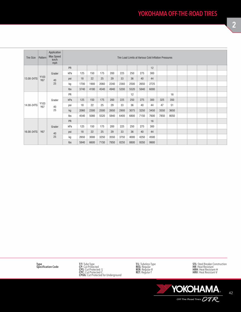
Tire Size Pattern
ApplicationMax Speed
km/hmph
Tire Load Limits at Various Cold Inflation Pressures
13.00-24TG Y103Y67
Grader
4025
PR 12
kPa 125 150 175 200 225 250 275 300
psi 18 22 25 29 33 36 40 44
kg 1700 1900 2060 2240 2360 2500 2650 2725
lbs 3740 4180 4540 4940 5200 5520 5840 6000
14.00-24TG Y103Y67
Grader
4025
PR 12 16
kPa 125 150 175 200 225 250 275 300 325 350
psi 18 22 25 29 33 36 40 44 47 51
kg 2060 2300 2500 2650 2900 3075 3250 3450 3550 3650
lbs 4540 5080 5520 5840 6400 6800 7150 7600 7850 8050
16.00-24TG Y67
Grader
4025
PR 16
kPa 125 150 175 200 225 250 275 300
psi 18 22 25 29 33 36 40 44
kg 2650 3000 3250 3550 3750 4000 4250 4500
lbs 5840 6600 7150 7850 8250 8800 9350 9900

43
TG: Tractor-Grade tire. Not for highway service.NHS: Not for highway service.
PSI × 0.0703 = kg/cm2 POUND × 0.4536 = kg PSI × 6.895 = kPa
12.00-20NHS Y67 18 06711 IND-3 - - - v - 1143 45.0 322 12.7 516 20.3 347 13.7 25.5 32 12.00-20 8.50V
12.00-24NHS
Y67 20 16746 IND-3 - - - v - 1240 48.8 318 12.5 558 22.0 350 13.8 26.4 33 11.00/12.00-24 8.50V
Y67 28 16787 IND-3 - - - v - 1240 48.8 318 12.5 558 22.0 350 13.8 26.4 33 11.00/12.00-24 8.50V
14.00-24NHS
Y69 30 06914 IND-4S - - - v - 1365 53.7 385 15.2 653 25.7 407 16.0 49.7 58 14.00-24/25 10.00W
Y67 28 16780 IND-3 - - - - v 1357 53.4 388 15.3 612 24.1 420 16.5 27.7 35 - 10.00VA
16.00-25Y67 36 16747 IND-3 - - - - v 1490 58.7 448 17.6 668 26.3 488 19.2 34.3 43 - 11.25-2.0
Y69PS 32 06919 IND-3S - - - - v 1470 57.9 417 16.4 658 25.9 457 18.0 43.8 55 - 11.25-2.0
18.00-25
Y67 40 16719 IND-3 - - - - v 1620 63.8 514 20.2 722 28.4 551 21.7 38.5 49 - 13.00-2.5
Y69 40 06915 IND-4S - - - - v 1650 65.0 530 20.9 748 29.4 557 21.9 58.7 74 - 13.00-2.5
Y69 40 06916 IND-5S - - - - v 1645 64.8 530 20.9 745 29.3 563 22.2 83.3 105 - 13.00-2.5
Y523 32 52304 IND-4 - - - - v 1652 65.0 517 20.4 772 30.4 541 21.3 61.3 77 - 13.00-2.5
Y523 40 02343 IND-4 - - - - v 1652 65.0 517 20.4 772 30.4 541 21.3 61.3 77 - 13.00-2.5
21.00-25Y67 40 16743 IND-3 - - - - v 1730 68.1 590 23.2 772 30.4 639 25.2 40.6 51 - 15.00-3.0
Y69 40 06972 IND-4S - - - - v 1779 70.0 601 23.7 798 31.4 640 25.2 56.2 71 - 15.00-3.0
18.00-33
Y69 40 06977 IND-4S - - - - v 1868 73.5 514 20.2 843 33.2 565 22.2 58.7 74 - 13.00-2.5
Y523 40 05326 IND-4 - - - - v 1850 72.8 518 20.4 869 34.2 542 21.3 56.2 71 - 13.00-2.5
Y523-SB 40 02335 IND-4 - - - - v 1850 72.8 518 20.4 869 34.2 542 21.3 56.2 71 - 13.00-2.5
21.00-35Y67 40 16781 IND-3 - - - - v 2004 78.9 580 22.8 935 36.8 622 24.5 42.0 53 - 15.00-3.0
Y69 42 06917 IND-4S - - - - v 2050 80.7 612 24.1 927 36.5 662 26.1 64.1 81 - 15.00-3.0
33.00-51 Y523 58 02355 IND-4 - - - - v 3056 120.3 934 36.8 1414 55.7 983 38.7 82.7 104 - 24.00-5.0
36.00-51 Y523 58 05230 IND-4 - - - - v 3198 125.9 1040 40.9 1379 54.3 1150 45.3 92.2 116 - 26.00-5.0
40.00-57 Y523 76 02338 IND-4 - - - - v 3584 141.1 1143 45.0 1567 61.7 1271 50.0 92.8 117 - 29.00-6.0
Tire Size Pattern Ply Rating
Part No.
TRA Code or
ApplicationCMPD TKPH TMPH
TypeInflated Dimensions
Static Loaded Radius
Static Loaded Width Groove Depth
Tube SizeRim Size Flange Height
Overall Diameter
Overall Width
T/T T/L mm inch mm inch mm inch mm inch mm 1/32
IndustrialBIAS: TECHNICAL DATA
*Not fixed yet. Yokohama will inform when available.
2
44
YOKOHAMA OFF-THE-ROAD TIRES
Type T/T: Tube Type T/L: Tubeless Type STL: Steel Breaker ConstructionSpecification Code CP: Cut Protected REG: Regular HR: Heat Resistant CPS: Cut Protected -S RER: Regular-R HRH: Heat Resistant-H CPC: Cut Protected-C RET: Regular-T HRV: Heat Resistant-V CPUG: Cut Protected for Underground
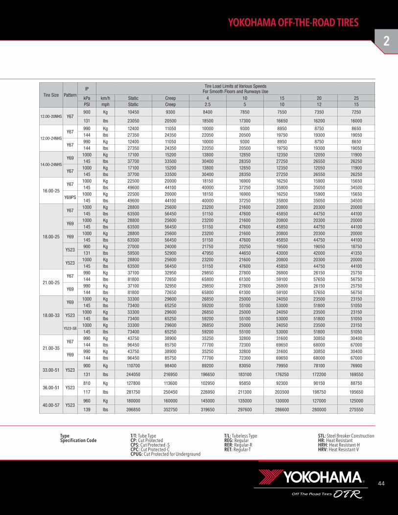
12.00-20NHS Y67900 Kg 10450 9300 8400 7850 7550 7350 7250
131 lbs 23050 20500 18500 17300 16650 16200 16000
12.00-24NHS
Y67990 Kg 12400 11050 10000 9300 8950 8750 8650144 lbs 27350 24350 22050 20500 19750 19300 19050
Y67990 Kg 12400 11050 10000 9300 8950 8750 8650144 lbs 27350 24350 22050 20500 19750 19300 19050
14.00-24NHS
Y691000 Kg 17100 15200 13800 12850 12350 12050 11900145 lbs 37700 33500 30400 28350 27250 26550 26250
Y671000 Kg 17100 15200 13800 12850 12350 12050 11900145 lbs 37700 33500 30400 28350 27250 26550 26250
16.00-25Y67
1000 Kg 22500 20000 18150 16900 16250 15900 15650145 lbs 49600 44100 40000 37250 35800 35050 34500
Y69PS1000 Kg 22500 20000 18150 16900 16250 15900 15650145 lbs 49600 44100 40000 37250 35800 35050 34500
18.00-25
Y671000 Kg 28800 25600 23200 21600 20800 20300 20000145 lbs 63500 56450 51150 47600 45850 44750 44100
Y691000 Kg 28800 25600 23200 21600 20800 20300 20000145 lbs 63500 56450 51150 47600 45850 44750 44100
Y691000 Kg 28800 25600 23200 21600 20800 20300 20000145 lbs 63500 56450 51150 47600 45850 44750 44100
Y523900 Kg 27000 24000 21750 20250 19500 19050 18750131 lbs 59500 52900 47950 44650 43000 42000 41350
Y5231000 Kg 28800 25600 23200 21600 20800 20300 20000145 lbs 63500 56450 51150 47600 45850 44750 44100
21.00-25Y67
990 Kg 37100 32950 29850 27800 26800 26150 25750144 lbs 81800 72650 65800 61300 59100 57650 56750
Y69990 Kg 37100 32950 29850 27800 26800 26150 25750144 lbs 81800 72650 65800 61300 59100 57650 56750
18.00-33
Y691000 Kg 33300 29600 26850 25000 24050 23500 23150145 lbs 73400 65250 59200 55100 53000 51800 51050
Y5231000 Kg 33300 29600 26850 25000 24050 23500 23150145 lbs 73400 65250 59200 55100 53000 51800 51050
Y523-SB1000 Kg 33300 29600 26850 25000 24050 23500 23150145 lbs 73400 65250 59200 55100 53000 51800 51050
21.00-35Y67
990 Kg 43750 38900 35250 32800 31600 30850 30400144 lbs 96450 85750 77700 72300 69650 68000 67000
Y69990 Kg 43750 38900 35250 32800 31600 30850 30400144 lbs 96450 85750 77700 72300 69650 68000 67000
33.00-51 Y523900 Kg 110700 98400 89200 83050 79950 78100 76900
131 lbs 244050 216950 196650 183100 176250 172200 169550
36.00-51 Y523810 Kg 127800 113600 102950 95850 92300 90150 88750
117 lbs 281750 250450 226950 211300 203500 198750 195650
40.00-57 Y523960 Kg 180000 160000 145000 135000 130000 127000 125000
139 lbs 396850 352750 319650 297600 286600 280000 275550
Tire Size PatternIP Tire Load Limits at Various Speeds
For Smooth Floors and Runways UsekPa km/h Static Creep 4 10 15 20 25PSI mph Static Creep 2.5 5 10 12 15

45
TG: Tractor-Grade tire. Not for highway service.NHS: Not for highway service.
PSI × 0.0703 = kg/cm2 POUND × 0.4536 = kg PSI × 6.895 = kPa
BIAS: TECHNICAL DATA
*Not fixed yet. Yokohama will inform when available.
Tire Size Pattern Ply Rating
Part No.
TRA Code or
ApplicationCMPD TKPH TMPH
TypeInflated Dimensions
Static Loaded Radius
Static Loaded Width Groove Depth
Tube SizeRim Size Flange Height
Overall Diameter
Overall Width
T/T T/L mm inch mm inch mm inch mm inch mm 1/32
17.5-25 Y573 36 57301 IND-3 - - - - v 1362 53.6 442 17.4 613 24.1 456 18.0 14.0 18 - 14.00-1.5
29.5-25 Y67 34 16793 IND-3 - - - - v 1863 73.3 765 * * * * 49.6 62 - 25.00-3.5
29.5-29 Y67 40 16796 IND-3 - - - - v 1970 77.6 780 30.7 860 33.9 820 32.3 49.6 62 - 25.00-3.5
33.25-29 Y67 38 16767 IND-3 - - - - v 2078 81.8 840 33.1 895 35.2 900 35.4 45.8 58 - 27.00-3.5
33.25-35 Y67 44 16749 IND-3 - - - - v 2278 89.7 854 33.6 990 39.0 923 36.3 47.1 59 - 27.00-3.5
Industrial
Wide Base Low-Seam Mining
32x15-15NHS Y67 28 26761 IND-3 CP - - v - 831 32.7 330 13.0 373 14.7 338 13.3 19.1 24 - 11.50
35x15-15NHS Y67 32 26762 IND-3 CP - - v - 914 36.0 363 14.3 422 16.6 371 14.6 26.2 33 - 10.50
36x11-15NHS Y67 24 26763 IND-3 CP - - v - 914 36.0 272 10.7 417 16.4 279 11.0 19.1 24 - 7.50
38x16-15NHS Y67 36 26764 IND-3 CP - - v - 993 39.1 378 14.9 442 17.4 394 15.5 25.4 32 - 11.50
39x15-20NHS Y20 36 02004 IND-3 CP - - v - 1006 39.6 340 13.4 * * * * 23.0 29 - 11.00TG
42x13-20NHS Y67 36 16782 IND-3 CP - - v - 1080 42.5 325 12.8 505 19.9 348 13.7 20.6 26 - 10.00WI
42x18-20NHS Y67 36 16788 IND-3 CP - - v - 1110 43.7 429 16.9 521 20.5 460 18.1 21.4 27 - 15.00T
44x15-20NHS Y67 36 16784 IND-3 CP - - v - 1153 45.4 348 13.7 523 20.6 371 14.6 24.6 31 - 10.00WI
44x18-20NHS Y67 36 16763 IND-3 CP - - v - 1151 45.3 442 17.4 526 20.7 462 18.2 25.4 32 - 15.00T
50x20-20NHS Y67 36 16769 IND-3 CP - - v - 1260 49.6 478 18.8 577 22.7 503 19.8 27.8 35 - 15.00T
Tire Size Pattern Ply Rating
Part No.
TRA Code or
ApplicationCMPD TKPH TMPH
TypeInflated Dimensions
Static Loaded Radius
Static Loaded Width Groove Depth
Tube SizeRim Size Flange Height
Overall Diameter
Overall Width
T/T T/L mm inch mm inch mm inch mm inch mm 1/32
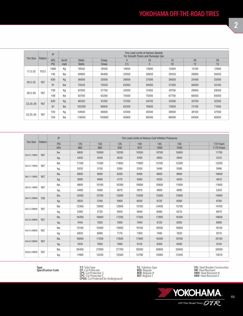
2
46
YOKOHAMA OFF-THE-ROAD TIRES
Type T/T: Tube Type T/L: Tubeless Type STL: Steel Breaker ConstructionSpecification Code CP: Cut Protected REG: Regular HR: Heat Resistant CPS: Cut Protected -S RER: Regular-R HRH: Heat Resistant-H CPC: Cut Protected-C RET: Regular-T HRV: Heat Resistant-V CPUG: Cut Protected for Underground
17.5-25 Y5731000 Kg 18550 16500 14950 13900 13400 13100 12900
145 lbs 40900 36400 32950 30650 29550 28900 28450
29.5-25 Y67630 Kg 36000 32000 29000 27000 26000 25400 25000
91 lbs 79350 70550 63950 59500 57300 56000 55100
29.5-29 Y67750 Kg 42500 37750 34200 31850 30700 29950 29500
109 lbs 93700 83200 75400 70200 67700 66050 65050
33.25-29 Y67630 Kg 46350 41200 37350 34750 33500 32700 32200
91 lbs 102200 90850 82350 76600 73850 72100 71000
33.25-35 Y67720 Kg 54000 48000 43500 40500 39000 38100 37500
104 lbs 119050 105800 95900 89300 86000 84000 82650
32x15-15NHS Y67lbs. 9800 10000 10200 10500 10700 10900 11700
kg. 4450 4540 4630 4760 4850 4940 5310
35x15-15NHS Y67lbs. 11100 11300 11600 11800 12100 12300 13200
kg. 5030 5130 5260 5350 5490 5580 5990
36x11-15NHS Y67lbs. 8800 9000 9200 9400 9600 9800 10600
kg. 3990 4080 4170 4260 4350 4450 4810
38x16-15NHS Y67lbs. 9900 10100 10300 10600 10800 11000 11800
kg. 4490 4580 4670 4810 4900 4990 5350
39x15-20NHS Y20lbs. 12400 12700 13000 13300 13500 13800 14900
kg. 5620 5760 5900 6030 6120 6260 6760
42x13-20NHS Y67lbs. 12300 12600 12900 13100 13400 13700 14700
kg. 5580 5720 5850 5940 6080 6210 6670
42x18-20NHS Y67lbs. 16400 16800 17200 17500 17900 18300 19600
kg. 7440 7620 7800 7940 8120 8300 8890
44x15-20NHS Y67lbs. 15100 15400 15800 16100 16500 16800 18100
kg. 6850 6990 7170 7300 7480 7620 8210
44x18-20NHS Y67lbs. 16800 17200 17600 17900 18300 18700 20100
kg. 7620 7800 7980 8120 8300 8480 9120
50x20-20NHS Y67lbs. 26400 27000 27700 28200 28800 29400 30000
kg. 11980 12250 12560 12790 13060 13340 13610
Tire Size PatternIP Tire Load Limits at Various Cold Inflation Pressures
PSI 125 130 135 140 145 150 170 FoamkPa 860 900 930 970 1000 1030 1170 Foam
Tire Size PatternIP Tire Load Limits at Various Speeds
For Smooth Floors and Runways UsekPa km/h Static Creep 4 10 15 20 25PSI mph Static Creep 2.5 5 10 12 15
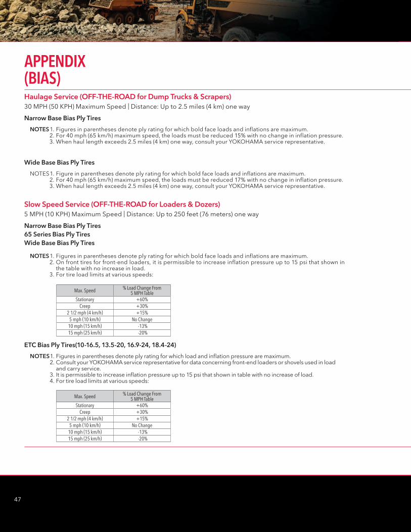
47
Haulage Service (OFF-THE-ROAD for Dump Trucks & Scrapers) 30 MPH (50 KPH) Maximum Speed | Distance: Up to 2.5 miles (4 km) one way
Slow Speed Service (OFF-THE-ROAD for Loaders & Dozers) 5 MPH (10 KPH) Maximum Speed | Distance: Up to 250 feet (76 meters) one way
Narrow Base Bias Ply Tires
Narrow Base Bias Ply Tires65 Series Bias Ply TiresWide Base Bias Ply Tires
ETC Bias Ply Tires(10-16.5, 13.5-20, 16.9-24, 18.4-24)
Wide Base Bias Ply Tires
NOTES 1. Figures in parentheses denote ply rating for which bold face loads and inflations are maximum. 2. For 40 mph (65 km/h) maximum speed, the loads must be reduced 15% with no change in inflation pressure. 3. When haul length exceeds 2.5 miles (4 km) one way, consult your YOKOHAMA service representative.
NOTES 1. Figures in parentheses denote ply rating for which bold face loads and inflations are maximum. 2. On front tires for front-end loaders, it is permissible to increase inflation pressure up to 15 psi that shown in
the table with no increase in load. 3. For tire load limits at various speeds:
NOTES 1. Figures in parentheses denote ply rating for which load and inflation pressure are maximum. 2. Consult your YOKOHAMA service representative for data concerning front-end loaders or shovels used in load
and carry service. 3. It is permissible to increase inflation pressure up to 15 psi that shown in table with no increase of load. 4. For tire load limits at various speeds:
NOTES 1. Figure in parentheses denote ply rating for which bold face loads and inflations are maximum. 2. For 40 mph (65 km/h) maximum speed, the loads must be reduced 17% with no change in inflation pressure. 3. When haul length exceeds 2.5 miles (4 km) one way, consult your YOKOHAMA service representative.
Max. Speed % Load Change From5 MPH Table
Stationary +60%Creep +30%
2 1/2 mph (4 km/h) +15%5 mph (10 km/h) No Change
10 mph (15 km/h) -13%15 mph (25 km/h) -20%
Max. Speed % Load Change From5 MPH Table
Stationary +60%Creep +30%
2 1/2 mph (4 km/h) +15%5 mph (10 km/h) No Change
10 mph (15 km/h) -13%15 mph (25 km/h) -20%
APPENDIX (BIAS)
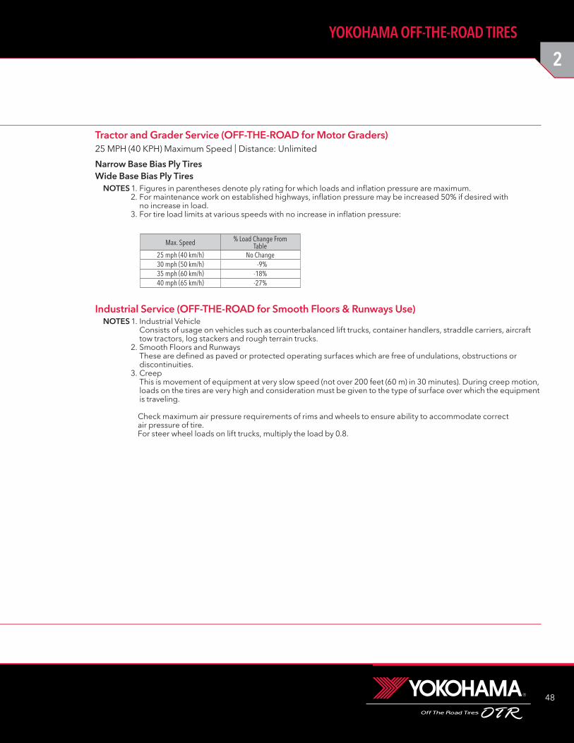
2
48
YOKOHAMA OFF-THE-ROAD TIRES
Industrial Service (OFF-THE-ROAD for Smooth Floors & Runways Use) NOTES 1. Industrial Vehicle
Consists of usage on vehicles such as counterbalanced lift trucks, container handlers, straddle carriers, aircraft tow tractors, log stackers and rough terrain trucks.
2. Smooth Floors and Runways These are defined as paved or protected operating surfaces which are free of undulations, obstructions or discontinuities.
3. Creep This is movement of equipment at very slow speed (not over 200 feet (60 m) in 30 minutes). During creep motion, loads on the tires are very high and consideration must be given to the type of surface over which the equipment is traveling.
Check maximum air pressure requirements of rims and wheels to ensure ability to accommodate correct air pressure of tire. For steer wheel loads on lift trucks, multiply the load by 0.8.
Tractor and Grader Service (OFF-THE-ROAD for Motor Graders) 25 MPH (40 KPH) Maximum Speed | Distance: Unlimited
Narrow Base Bias Ply TiresWide Base Bias Ply Tires
NOTES 1. Figures in parentheses denote ply rating for which loads and inflation pressure are maximum. 2. For maintenance work on established highways, inflation pressure may be increased 50% if desired with
no increase in load. 3. For tire load limits at various speeds with no increase in inflation pressure:
Max. Speed % Load Change FromTable
25 mph (40 km/h) No Change30 mph (50 km/h) -9%35 mph (60 km/h) -18%40 mph (65 km/h) -27%
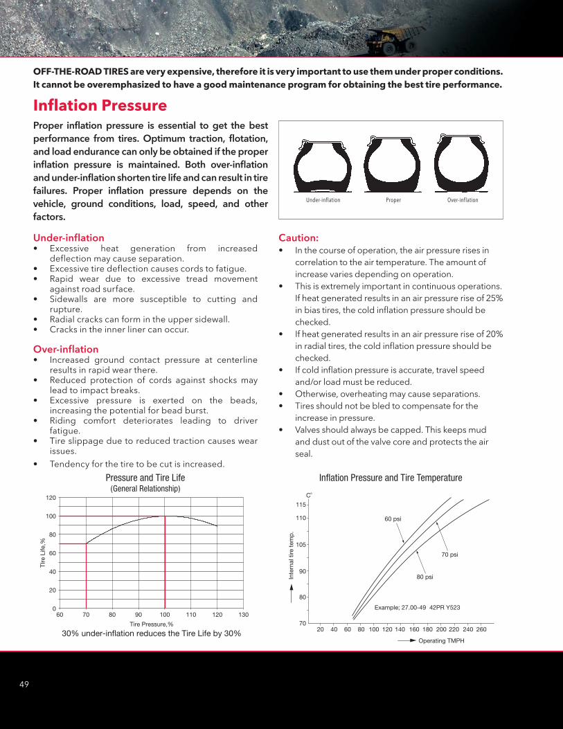
49
Inflation Pressure
Caution:• In the course of operation, the air pressure rises in
correlation to the air temperature. The amount of increase varies depending on operation.
• This is extremely important in continuous operations. If heat generated results in an air pressure rise of 25% in bias tires, the cold inflation pressure should be checked.
• If heat generated results in an air pressure rise of 20% in radial tires, the cold inflation pressure should be checked.
• If cold inflation pressure is accurate, travel speed and/or load must be reduced.
• Otherwise, overheating may cause separations. • Tires should not be bled to compensate for the
increase in pressure.• Valves should always be capped. This keeps mud
and dust out of the valve core and protects the air seal.
60 70 80 90 100 110 120 130
TIre
Life
,%
Tire Pressure,%
30% under-inflation reduces the Tire Life by 30%
0
20
40
60
80
100
120
Pressure and Tire Life(General Relationship)
C˚
115
110
105
90
80
7020 40 60 80 100 120 140 160 180 200 220 240 260
Operating TMPH
Example; 27.00-49 42PR Y523
Inte
rnal
tire
tem
p.
80 psi
70 psi
60 psi
Inflation Pressure and Tire Temperature
Under-inflation Proper Over-inflation
OFF-THE-ROAD TIRES are very expensive, therefore it is very important to use them under proper conditions. It cannot be overemphasized to have a good maintenance program for obtaining the best tire performance.
Under-inflation• Excessive heat generation from increased
deflection may cause separation.• Excessive tire deflection causes cords to fatigue.• Rapid wear due to excessive tread movement
against road surface.• Sidewalls are more susceptible to cutting and
rupture.• Radial cracks can form in the upper sidewall.• Cracks in the inner liner can occur.
Over-inflation• Increased ground contact pressure at centerline
results in rapid wear there.• Reduced protection of cords against shocks may
lead to impact breaks.• Excessive pressure is exerted on the beads,
increasing the potential for bead burst.• Riding comfort deteriorates leading to driver
fatigue.• Tire slippage due to reduced traction causes wear
issues.• Tendency for the tire to be cut is increased.
Proper inflation pressure is essential to get the best performance from tires. Optimum traction, flotation, and load endurance can only be obtained if the proper inflation pressure is maintained. Both over-inflation and under-inflation shorten tire life and can result in tire failures. Proper inflation pressure depends on the vehicle, ground conditions, load, speed, and other factors.
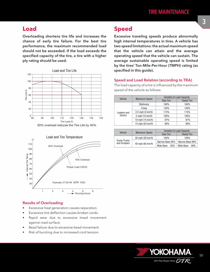
3
50
TIRE MAINTENANCE
Overloading shortens tire life and increases the chance of early tire failure. For the best tire performance, the maximum recommended load should not be exceeded. If the load exceeds the specified capacity of the tire, a tire with a higher ply rating should be used.
Load
80 90 100 110 120 130 140 150
TIre
Life
,%
Tire Load,%
30% overload reduces the Tire Life by 40%
0
20
40
60
80
100
120Load and Tire Life
C˚
110
100
90
80
70
60
50
40
30
1 2 3 4 5 6Running Hours
Inte
rnal
Tire
Tem
p.
20% Overload
10% Overload
Proper Load (100%)
Example; 27.00-49 42PR Y523
Load and Tire Temperature
Excessive traveling speeds produce abnormally high internal temperatures in tires. A vehicle has two speed limitations: the actual maximum speed that the vehicle can attain and the average operating speed that the vehicle can sustain. The average sustainable operating speed is limited by the tires' Ton-Mile-Per-Hour (TMPH) rating (as specified in this guide).
Speed and Load Relation (according to TRA)The load capacity of a tire is influenced by the maximum speed of the vehicle as follows:
Speed
Vehicle Maximum SpeedVariation In Load Capacity
Bias Tire Radial Tire
Loaders and Dozers
Stationary 160% 160%
Creep 130% 130%
2.5 mph (4 km/h) 115% 115%
5 mph (10 km/h) 100% 100%
10 mph (15 km/h) 87% 87%
15 mph (25 km/h) 80% 80%
Vehicle Maximum SpeedVariation In Load Capacity
Bias Tire Radial Tire
Dump Trucks and Scrapers
30 mph (50 km/h) 100% 100%
40 mph (65 km/h)Narrow Base 85% Narrow Base 88%
Wide Base 83% Wide Base 88%
Results of Overloading• Excessive heat generation causes separation.• Excessive tire deflection causes broken cords.• Rapid wear due to excessive tread movement
against road surface.• Bead failure due to excessive bead movement.• Risk of bursting due to increased cord tension.
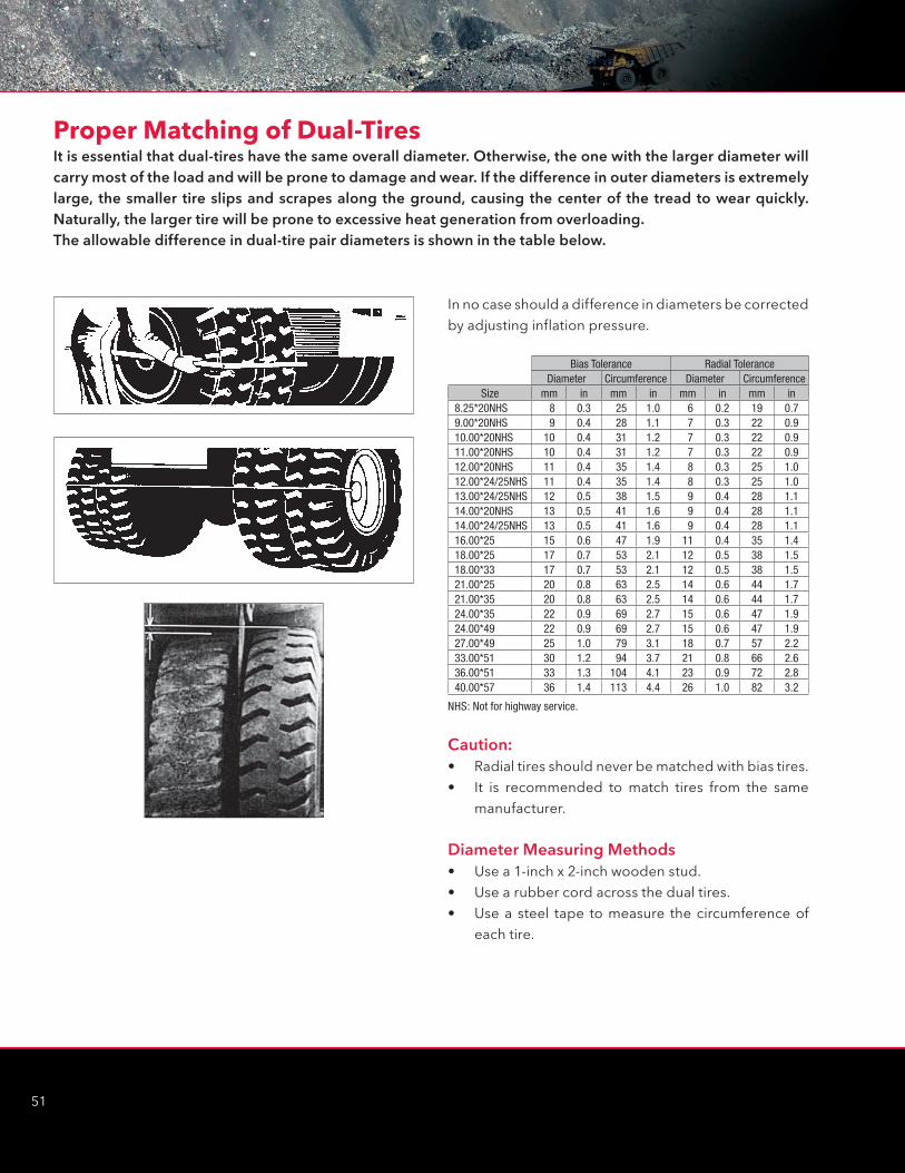
51
It is essential that dual-tires have the same overall diameter. Otherwise, the one with the larger diameter will carry most of the load and will be prone to damage and wear. If the difference in outer diameters is extremely large, the smaller tire slips and scrapes along the ground, causing the center of the tread to wear quickly. Naturally, the larger tire will be prone to excessive heat generation from overloading.The allowable difference in dual-tire pair diameters is shown in the table below.
Proper Matching of Dual-Tires
In no case should a difference in diameters be corrected by adjusting inflation pressure.
Caution:• Radial tires should never be matched with bias tires.• It is recommended to match tires from the same
manufacturer.
Diameter Measuring Methods• Use a 1-inch x 2-inch wooden stud.• Use a rubber cord across the dual tires.• Use a steel tape to measure the circumference of
each tire.
Bias Tolerance Radial ToleranceDiameter Circumference Diameter Circumference
Size mm in mm in mm in mm in8.25*20NHS 8 0.3 25 1.0 6 0.2 19 0.79.00*20NHS 9 0.4 28 1.1 7 0.3 22 0.910.00*20NHS 10 0.4 31 1.2 7 0.3 22 0.911.00*20NHS 10 0.4 31 1.2 7 0.3 22 0.912.00*20NHS 11 0.4 35 1.4 8 0.3 25 1.012.00*24/25NHS 11 0.4 35 1.4 8 0.3 25 1.013.00*24/25NHS 12 0.5 38 1.5 9 0.4 28 1.114.00*20NHS 13 0.5 41 1.6 9 0.4 28 1.114.00*24/25NHS 13 0.5 41 1.6 9 0.4 28 1.116.00*25 15 0.6 47 1.9 11 0.4 35 1.418.00*25 17 0.7 53 2.1 12 0.5 38 1.518.00*33 17 0.7 53 2.1 12 0.5 38 1.521.00*25 20 0.8 63 2.5 14 0.6 44 1.721.00*35 20 0.8 63 2.5 14 0.6 44 1.724.00*35 22 0.9 69 2.7 15 0.6 47 1.924.00*49 22 0.9 69 2.7 15 0.6 47 1.927.00*49 25 1.0 79 3.1 18 0.7 57 2.233.00*51 30 1.2 94 3.7 21 0.8 66 2.636.00*51 33 1.3 104 4.1 23 0.9 72 2.840.00*57 36 1.4 113 4.4 26 1.0 82 3.2
NHS: Not for highway service.
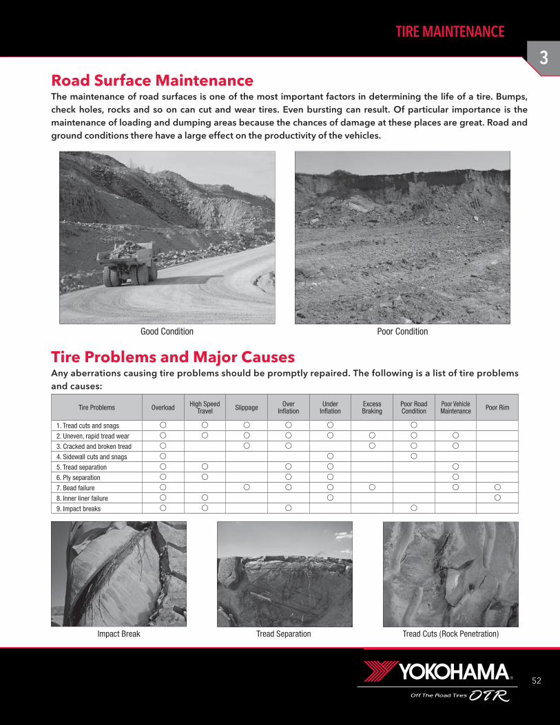
3
52
TIRE MAINTENANCE
Road Surface MaintenanceThe maintenance of road surfaces is one of the most important factors in determining the life of a tire. Bumps, check holes, rocks and so on can cut and wear tires. Even bursting can result. Of particular importance is the maintenance of loading and dumping areas because the chances of damage at these places are great. Road and ground conditions there have a large effect on the productivity of the vehicles.
Good Condition Poor Condition
Tire Problems and Major CausesAny aberrations causing tire problems should be promptly repaired. The following is a list of tire problems and causes:
Impact Break Tread Separation Tread Cuts (Rock Penetration)
Tire Problems Overload High Speed Travel Slippage Over
InflationUnder
InflationExcess Braking
Poor Road Condition
Poor Vehicle Maintenance Poor Rim
1. Tread cuts and snags v v v v v v
2. Uneven, rapid tread wear v v v v v v v v
3. Cracked and broken tread v v v v v v
4. Sidewall cuts and snags v v v
5. Tread separation v v v v v
6. Ply separation v v v v v
7. Bead failure v v v v v v v
8. Inner liner failure v v v v
9. Impact breaks v v v v
53
Even if tires and roads are properly maintained, tire life can be seriously shortened by improper use. The following are musts for maximum efficiency.
General:• Avoid abrupt starts and stops.
• Do not operate on road shoulders.
• Reduce speed on turns.
• Do not turn wheels while stationary.
• Do not spin tires.
• Maintain proper inflation pressure.
• Remove any objects, such as rocks which get stuck in the tread or between dual tires.
• Check tires, rims and valves regularly for any abnormalities.
• Repair any damaged tires immediately.
• Avoid rocks at loading and dumping areas.
• Avoid running over oil or grease spills.
Loader Operating:• Keep loading areas clear of rocks and other
obstacles.
• Avoid spilling load around the tires.
• Avoid over-loading.
• Load to the center of the dump truck's decks.
Motor Scraper Operating:• Prevent tires from slipping when loading.
• Avoid cornering when the pusher is in operation.
Operating under Ambient Temperatures below -40˚F:• Consult Yokohama Tire Corporation.
In order to prevent tire troubles, it is helpful to make routine visual check-ups of the tire, rim, valve, inflation pressure, etc. Make inspections for the following and carry out any procedure recommended.
Tire Tread:• Remove foreign matter from the tread.
• Repair any damage reaching the carcass.
• If separation exists, remove tire and examine if repair is necessary.
• If damage reached carcass, remove tire and repair.
• If cuts or chips reach carcass, repair.
• Cracks in tread groove may be source of air leakage; check inflation pressure.
• Uneven wear may be caused by improper inflation pressure. Rotate tires if necessary.
• Damage from contact with vehicle should be avoided. Alter body parts if possible. Repair any tire damage if necessary.
• Oil or grease on tire should be washed off.
Shoulder and Sidewall:• Repair any cuts reaching the carcass.
• Identify cause of cracks e.g. from under-inflation, overloading, ozone or cut growth and repair if necessary.
• Wash off oil or grease spots.
Valve:• Replace valve or valve parts if leakage exists from
valve core, deflection of stem or extension.
• Ensure valve cap is in position.
Dual Tires:• Remove any foreign object stuck between duals.
• Repair stone ejector if bent or out of position.
Inflation Pressure:• Adjust if not proper.
• Detect location and repair if leakage exists.
Rim:• Replace if deformation or cracks exist.
Tire Appearance Check-upInstructions for Operations
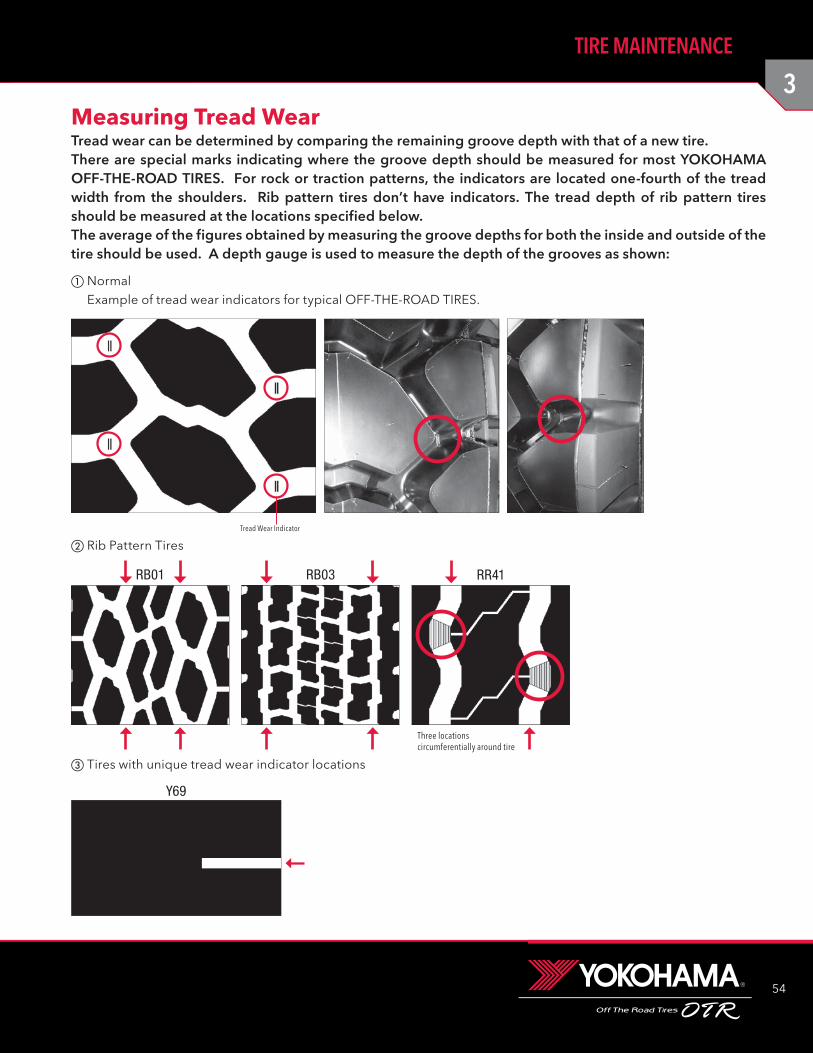
3
54
TIRE MAINTENANCE
Measuring Tread WearTread wear can be determined by comparing the remaining groove depth with that of a new tire. There are special marks indicating where the groove depth should be measured for most YOKOHAMA OFF-THE-ROAD TIRES. For rock or traction patterns, the indicators are located one-fourth of the tread width from the shoulders. Rib pattern tires don’t have indicators. The tread depth of rib pattern tires should be measured at the locations specified below. The average of the figures obtained by measuring the groove depths for both the inside and outside of the tire should be used. A depth gauge is used to measure the depth of the grooves as shown:
Tires with unique tread wear indicator locations
Normal
Example of tread wear indicators for typical OFF-THE-ROAD TIRES.
Tread Wear Indicator
Rib Pattern Tires
RB01 RB03
Three locations circumferentially around tire
RR41
Y69
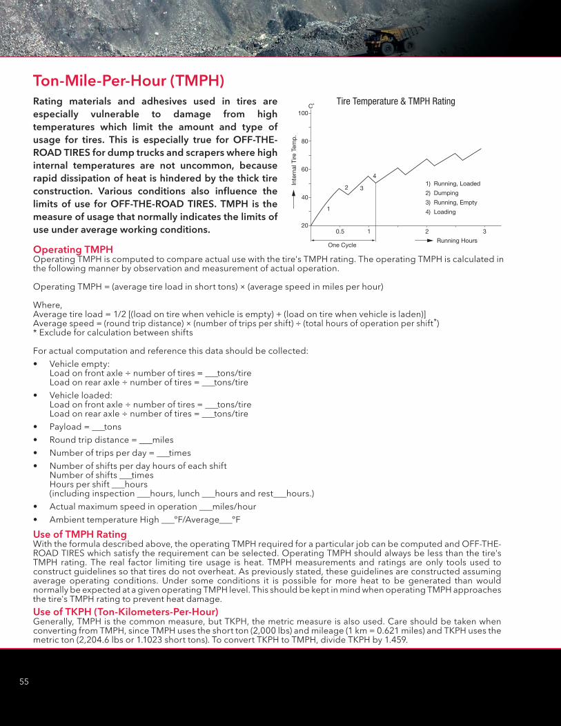
55
C˚
0.5 1 2 3
100
80
60
40
20
One CycleRunning Hours
1) Running, Loaded
2) Dumping
3) Running, Empty
4) Loading1
2 3
4
Inte
rnal
Tire
Tem
p.
Tire Temperature & TMPH Rating
Ton-Mile-Per-Hour (TMPH)Rating materials and adhesives used in tires are especially vulnerable to damage from high temperatures which limit the amount and type of usage for tires. This is especially true for OFF-THE-ROAD TIRES for dump trucks and scrapers where high internal temperatures are not uncommon, because rapid dissipation of heat is hindered by the thick tire construction. Various conditions also influence the limits of use for OFF-THE-ROAD TIRES. TMPH is the measure of usage that normally indicates the limits of use under average working conditions.
Operating TMPHOperating TMPH is computed to compare actual use with the tire's TMPH rating. The operating TMPH is calculated in the following manner by observation and measurement of actual operation.
Operating TMPH = (average tire load in short tons) × (average speed in miles per hour)
Where,Average tire load = 1/2 [(load on tire when vehicle is empty) + (load on tire when vehicle is laden)]Average speed = (round trip distance) × (number of trips per shift) ÷ (total hours of operation per shift*) * Exclude for calculation between shifts
For actual computation and reference this data should be collected:
• Vehicle empty: Load on front axle ÷ number of tires = _tons/tire Load on rear axle ÷ number of tires = _tons/tire
• Vehicle loaded: Load on front axle ÷ number of tires = _tons/tire Load on rear axle ÷ number of tires = _tons/tire
• Payload = _tons
• Round trip distance = _miles
• Number of trips per day = _times
• Number of shifts per day hours of each shift Number of shifts _times Hours per shift _hours (including inspection _hours, lunch _hours and rest_hours.)
• Actual maximum speed in operation _miles/hour
• Ambient temperature High _ºF/Average_ºF
Use of TMPH RatingWith the formula described above, the operating TMPH required for a particular job can be computed and OFF-THE-ROAD TIRES which satisfy the requirement can be selected. Operating TMPH should always be less than the tire's TMPH rating. The real factor limiting tire usage is heat. TMPH measurements and ratings are only tools used to construct guidelines so that tires do not overheat. As previously stated, these guidelines are constructed assuming average operating conditions. Under some conditions it is possible for more heat to be generated than would normally be expected at a given operating TMPH level. This should be kept in mind when operating TMPH approaches the tire's TMPH rating to prevent heat damage.
Use of TKPH (Ton-Kilometers-Per-Hour)Generally, TMPH is the common measure, but TKPH, the metric measure is also used. Care should be taken when converting from TMPH, since TMPH uses the short ton (2,000 lbs) and mileage (1 km = 0.621 miles) and TKPH uses the metric ton (2,204.6 lbs or 1.1023 short tons). To convert TKPH to TMPH, divide TKPH by 1.459.
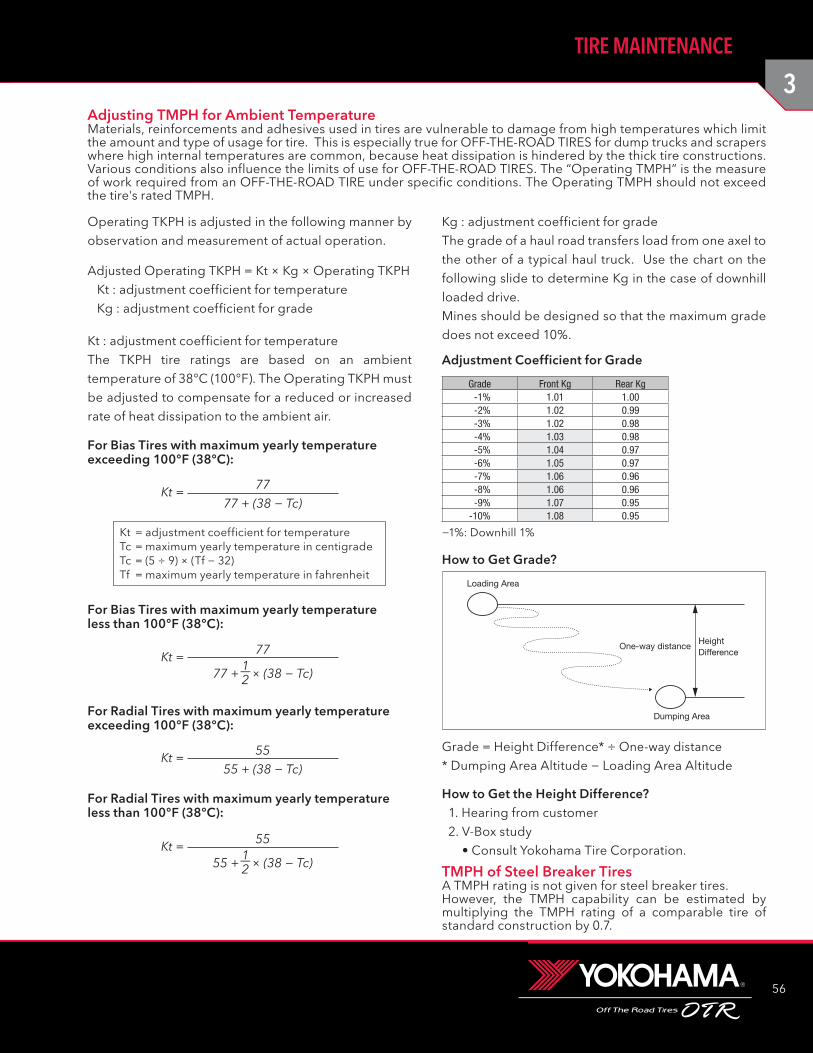
3
56
TIRE MAINTENANCE
Adjusting TMPH for Ambient TemperatureMaterials, reinforcements and adhesives used in tires are vulnerable to damage from high temperatures which limit the amount and type of usage for tire. This is especially true for OFF-THE-ROAD TIRES for dump trucks and scrapers where high internal temperatures are common, because heat dissipation is hindered by the thick tire constructions. Various conditions also influence the limits of use for OFF-THE-ROAD TIRES. The “Operating TMPH” is the measure of work required from an OFF-THE-ROAD TIRE under specific conditions. The Operating TMPH should not exceed the tire's rated TMPH.
TMPH of Steel Breaker TiresA TMPH rating is not given for steel breaker tires.However, the TMPH capability can be estimated by multiplying the TMPH rating of a comparable tire of standard construction by 0.7.
Kg : adjustment coefficient for gradeThe grade of a haul road transfers load from one axel to the other of a typical haul truck. Use the chart on the following slide to determine Kg in the case of downhill loaded drive.Mines should be designed so that the maximum grade does not exceed 10%.
Grade = Height Difference* ÷ One-way distance
* Dumping Area Altitude − Loading Area Altitude
How to Get the Height Difference? 1. Hearing from customer 2. V-Box study
• Consult Yokohama Tire Corporation.
Adjustment Coefficient for Grade
Grade Front Kg Rear Kg-1% 1.01 1.00-2% 1.02 0.99-3% 1.02 0.98-4% 1.03 0.98-5% 1.04 0.97-6% 1.05 0.97-7% 1.06 0.96-8% 1.06 0.96-9% 1.07 0.95
-10% 1.08 0.95
−1%: Downhill 1%
How to Get Grade?
Loading Area
One-way distanceHeight Difference
Dumping Area
Operating TKPH is adjusted in the following manner by observation and measurement of actual operation.
7777 + (38 − Tc)
Kt =
For Bias Tires with maximum yearly temperature exceeding 100°F (38°C):
For Bias Tires with maximum yearly temperature less than 100°F (38°C):
Kt = adjustment coefficient for temperatureTc = maximum yearly temperature in centigradeTc = (5 ÷ 9) × (Tf − 32)Tf = maximum yearly temperature in fahrenheit
77Kt =77 + × (38 − Tc)
1−2
5555 + (38 − Tc)
Kt =
For Radial Tires with maximum yearly temperature exceeding 100°F (38°C):
For Radial Tires with maximum yearly temperature less than 100°F (38°C):
55Kt =55 + × (38 − Tc)
1−2
Kt : adjustment coefficient for temperatureThe TKPH tire ratings are based on an ambient temperature of 38°C (100°F). The Operating TKPH must be adjusted to compensate for a reduced or increased rate of heat dissipation to the ambient air.
Adjusted Operating TKPH = Kt × Kg × Operating TKPH Kt : adjustment coefficient for temperature Kg : adjustment coefficient for grade
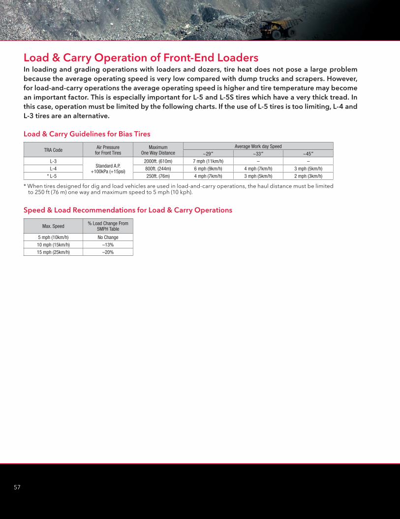
57
Load & Carry Operation of Front-End LoadersIn loading and grading operations with loaders and dozers, tire heat does not pose a large problem because the average operating speed is very low compared with dump trucks and scrapers. However, for load-and-carry operations the average operating speed is higher and tire temperature may become an important factor. This is especially important for L-5 and L-5S tires which have a very thick tread. In this case, operation must be limited by the following charts. If the use of L-5 tires is too limiting, L-4 and L-3 tires are an alternative.
Load & Carry Guidelines for Bias Tires
Speed & Load Recommendations for Load & Carry Operations
TRA Code Air Pressurefor Front Tires
MaximumOne Way Distance
Average Work day Speed
~29” ~33” ~45”L-3
Standard A.P.+100kPa (+15psi)
2000ft. (610m) 7 mph (11km/h) – –
L-4 800ft. (244m) 6 mph (9km/h) 4 mph (7km/h) 3 mph (5km/h)
* L-5 250ft. (76m) 4 mph (7km/h) 3 mph (5km/h) 2 mph (3km/h)
Max. Speed % Load Change From5MPH Table
5 mph (10km/h) No Change
10 mph (15km/h) –13%
15 mph (25km/h) –20%
* When tires designed for dig and load vehicles are used in load-and-carry operations, the haul distance must be limited to 250 ft (76 m) one way and maximum speed to 5 mph (10 kph).
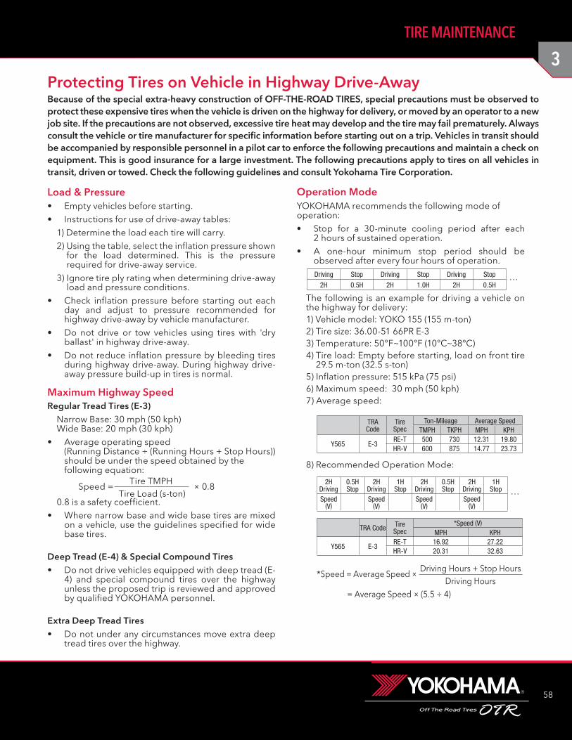
3
58
TIRE MAINTENANCE
Because of the special extra-heavy construction of OFF-THE-ROAD TIRES, special precautions must be observed to protect these expensive tires when the vehicle is driven on the highway for delivery, or moved by an operator to a new job site. If the precautions are not observed, excessive tire heat may develop and the tire may fail prematurely. Always consult the vehicle or tire manufacturer for specific information before starting out on a trip. Vehicles in transit should be accompanied by responsible personnel in a pilot car to enforce the following precautions and maintain a check on equipment. This is good insurance for a large investment. The following precautions apply to tires on all vehicles in transit, driven or towed. Check the following guidelines and consult Yokohama Tire Corporation.
Load & Pressure• Empty vehicles before starting.
• Instructions for use of drive-away tables:
1) Determine the load each tire will carry.
2) Using the table, select the inflation pressure shown for the load determined. This is the pressure required for drive-away service.
3) Ignore tire ply rating when determining drive-away load and pressure conditions.
• Check inflation pressure before starting out each day and adjust to pressure recommended for highway drive-away by vehicle manufacturer.
• Do not drive or tow vehicles using tires with 'dry ballast' in highway drive-away.
• Do not reduce inflation pressure by bleeding tires during highway drive-away. During highway drive-away pressure build-up in tires is normal.
Maximum Highway Speed�Regular Tread Tires (E-3)
Narrow Base: 30 mph (50 kph)Wide Base: 20 mph (30 kph)
• Average operating speed (Running Distance ÷ (Running Hours + Stop Hours)) should be under the speed obtained by the following equation:
0.8 is a safety coefficient.
• Where narrow base and wide base tires are mixed on a vehicle, use the guidelines specified for wide base tires.
Deep Tread (E-4) & Special Compound Tires• Do not drive vehicles equipped with deep tread (E-
4) and special compound tires over the highway unless the proposed trip is reviewed and approved by qualified YOKOHAMA personnel.
Extra Deep Tread Tires• Do not under any circumstances move extra deep
tread tires over the highway.
Operation ModeYOKOHAMA recommends the following mode of operation:
• Stop for a 30-minute cooling period after each 2 hours of sustained operation.
• A one-hour minimum stop period should be observed after every four hours of operation.
The following is an example for driving a vehicle on the highway for delivery:1) Vehicle model: YOKO 155 (155 m-ton)2) Tire size: 36.00-51 66PR E-33) Temperature: 50ºF~100ºF (10ºC~38ºC)4) Tire load: Empty before starting, load on front tire
29.5 m-ton (32.5 s-ton)5) Inflation pressure: 515 kPa (75 psi)6) Maximum speed: 30 mph (50 kph)7) Average speed:
8) Recommended Operation Mode:
Tire TMPHTire Load (s-ton)
× 0.8Speed =
TRACode
Tire Spec
Ton-Mileage Average SpeedTMPH TKPH MPH KPH
Y565 E-3RE-T 500 730 12.31 19.80HR-V 600 875 14.77 23.73
Driving Stop Driving Stop Driving Stop
2H 0.5H 2H 1.0H 2H 0.5H…
TRA Code Tire Spec
*Speed (V)MPH KPH
Y565 E-3RE-T 16.92 27.22HR-V 20.31 32.63
Driving Hours + Stop HoursDriving Hours
= Average Speed × (5.5 ÷ 4)
*Speed = Average Speed ×
2HDriving
0.5HStop
2HDriving
1HStop
2HDriving
0.5HStop
2HDriving
1HStop
Speed(V)
Speed(V)
Speed(V)
Speed(V)
…
Protecting Tires on Vehicle in Highway Drive-Away

59
Tire Size Designation
Tire Load Limits at Various Cold Inflation PressuresRadial Ply
kPa 240 275 310 345 380 415 450 485 515 550 585 620 655 690 725 760psi 35 40 45 50 55 60 65 70 75 80 85 90 95 100 105 110
Diagonal PlykPa 170 205 240 275 310 345 380 415 450 485 515 550 585 620 655 690psi 25 30 35 40 45 50 55 60 65 70 75 80 85 90 95 100
16.00*25kg 2440 2710 2970 3220 3450 3650 3880 4080 4260 4470 4630 4810 4990 5170 5350 5490lbs 5380 5980 6550 7100 7600 8050 8550 9000 9400 9850 10200 10600 11000 11400 11800 12100
18.00*25kg 3150 3520 3860 4150 4450 4720 4990 5260 5530 5760 5990 6210 6440 6670 6890 7120lbs 6950 7750 8500 9150 9800 10400 11000 11600 12200 12700 13200 13700 14200 14700 15200 15700
21.00*25kg 4060 4330 4940 5350 5720 6080 6440 6760 7120 7440 7710 8030 8300 8570 8890 9160lbs 8950 9550 10900 11800 12600 13400 14200 14900 15700 16400 17000 17700 18300 18900 19600 20200
24.00*25(**)kg 5260 5850 6400 6890 7390 7890 8350 8750 9160 9570 9980 10390 10750 11110 11480 11790lbs 11600 12900 14100 15200 16300 17400 18400 19300 20200 21100 22000 22900 23700 24500 25300 26000
24.00*29kg 5620 6260 6850 7390 7940 8440 8940 9390 9840 10250 10700 11110 11520 11880 12290 12660lbs 12400 13800 15100 16300 17500 18600 19700 20700 21700 22600 23600 24500 25400 26200 27100 27900
18.00*33kg 3650 4080 4470 4810 5170 5490 5810 6120 6400 6670 6990 7210 7480 7760 7980 8260lbs 8050 9000 9850 10600 11400 12100 12800 13500 14100 14700 15400 15900 16500 17100 17600 18200
27.00*33(**)kg 7350 8210 8980 9710 10390 11070 11700 12290 12880 13470 14020 14560 15060 15600 16100 16600lbs 16200 18100 19800 21400 22900 24400 25800 27100 28400 29700 30900 32100 33200 34400 35500 36600
30.00*33(**)kg 9070 10070 11020 11930 12790 13610 14380 15100 15830 16560 17240 17870 18550 19140 19780 20370lbs 20000 22200 24300 26300 28200 30000 31700 33300 34900 36500 38000 39400 40900 42200 43600 44900
21.00*35kg 4810 5350 5850 6350 6800 7210 7670 8030 8440 8800 9160 9530 9840 10210 10520 10840lbs 10600 11800 12900 14000 15000 15900 16900 17700 18600 19400 20200 21000 21700 22500 23200 23900
24.00*35kg 6170 6850 7530 8120 8710 9250 9800 10300 10800 11250 11700 12160 12610 13060 13470 13880lbs 13600 15100 16600 17900 19200 20400 21600 22700 23800 24800 25800 26800 27800 28800 29700 30600
24.00*43(**)kg 6890 7670 8390 9070 9710 10300 10890 11480 12020 12560 13060 13560 14060 14560 15010 15470lbs 15200 16900 18500 20000 21400 22700 24000 25300 26500 27700 28800 29900 31000 32100 33100 34100
18.00*49(**)kg 4630 5170 5620 6080 6530 6940 7350 7710 8070 8440 8800 9160 9480 9800 10120 10430lbs 10200 11400 12400 13400 14400 15300 16200 17000 17800 18600 19400 20200 20900 21600 22300 23000
21.00*49(**)kg 5850 6490 7120 7710 8260 8750 9250 9750 10210 10660 11110 11520 11930 12340 12750 13150lbs 12900 14300 15700 17000 18200 19300 20400 21500 22500 23500 24500 25400 26300 27200 28100 29000
24.00*49kg 7390 8210 9030 9750 10430 11110 11750 12340 12930 13520 14060 14610 15150 15650 16150 16650lbs 16300 18100 19900 21500 23000 24500 25900 27200 28500 29800 31000 32200 33400 34500 35600 36700
27.00*49kg 9070 10070 11020 11930 12790 13610 14380 15100 15830 16560 17240 17870 18550 19190 19780 20370lbs 20000 22200 24300 26300 28200 30000 31700 33300 34900 36500 38000 39400 40900 42300 43600 44900
30.00*51kg 11200 12470 13650 14740 15830 16830 17780 18730 19600 20500 21320 22140 22950 23720 24490 25220lbs 24700 27500 30100 32500 34900 37100 39200 41300 43200 45200 47000 48800 50600 52300 54000 55600
33.00*51kg 12970 14470 15830 17100 18330 19500 20590 21680 22730 23720 24720 25630 26580 27440 28350 29260lbs 28600 31900 34900 37700 40400 43000 45400 47800 50100 52300 54500 56500 58600 60500 62500 64500
36.00*51kg 15830 17600 19280 20820 22320 23720 25080 26400 27670 28800 30160 31300 32430 33570 34470 35610lbs 34900 38800 42500 45900 49200 52300 55300 58200 61000 63500 66500 69000 71500 74000 76000 78500
40.00*57kg 20190 22500 24590 26580 28580 30390 31980 33790 35380 36970 38330 39920 41280 42640 44230 45360lbs 44500 49600 54200 58600 63000 67000 70500 74500 78000 81500 84500 88000 91000 94000 97500 100000
Load and Inflation Pressure Table for Transit (as recommended by the TRA)Narrow Base Earthmover Tires in Drive-Away Service Only30 MPH (50 KPH) Maximum Speed
* Tire size designation will include"R"(Radial Ply) or "-"(Diagonal or Bias Ply)**Not available from Yokohama Tire Corporation.NOTES: Figures are subjected to change without prior notice.
Protecting Tires on Vehicle in Highway Drive-Away
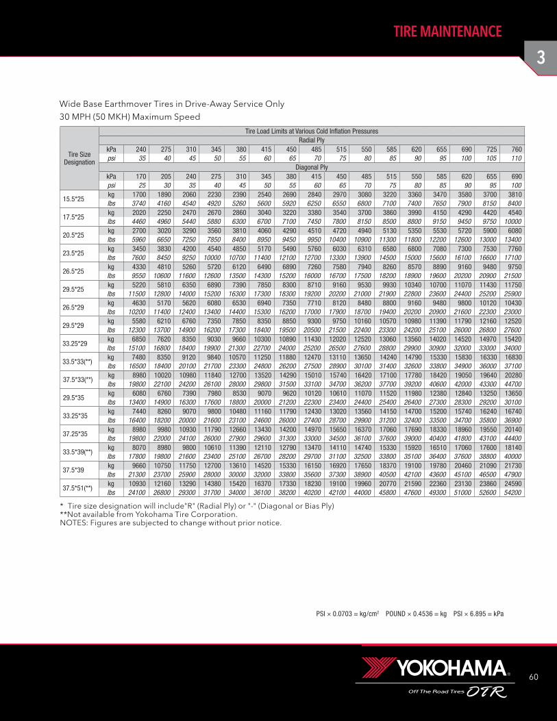
3
60
TIRE MAINTENANCE
PSI × 0.0703 = kg/cm2 POUND × 0.4536 = kg PSI × 6.895 = kPa
Tire Size Designation
Tire Load Limits at Various Cold Inflation PressuresRadial Ply
kPa 240 275 310 345 380 415 450 485 515 550 585 620 655 690 725 760psi 35 40 45 50 55 60 65 70 75 80 85 90 95 100 105 110
Diagonal PlykPa 170 205 240 275 310 345 380 415 450 485 515 550 585 620 655 690psi 25 30 35 40 45 50 55 60 65 70 75 80 85 90 95 100
15.5*25kg 1700 1890 2060 2230 2390 2540 2690 2840 2970 3080 3220 3360 3470 3580 3700 3810lbs 3740 4160 4540 4920 5260 5600 5920 6250 6550 6800 7100 7400 7650 7900 8150 8400
17.5*25kg 2020 2250 2470 2670 2860 3040 3220 3380 3540 3700 3860 3990 4150 4290 4420 4540lbs 4460 4960 5440 5880 6300 6700 7100 7450 7800 8150 8500 8800 9150 9450 9750 10000
20.5*25kg 2700 3020 3290 3560 3810 4060 4290 4510 4720 4940 5130 5350 5530 5720 5900 6080lbs 5960 6650 7250 7850 8400 8950 9450 9950 10400 10900 11300 11800 12200 12600 13000 13400
23.5*25kg 3450 3830 4200 4540 4850 5170 5490 5760 6030 6310 6580 6800 7080 7300 7530 7760lbs 7600 8450 9250 10000 10700 11400 12100 12700 13300 13900 14500 15000 15600 16100 16600 17100
26.5*25kg 4330 4810 5260 5720 6120 6490 6890 7260 7580 7940 8260 8570 8890 9160 9480 9750lbs 9550 10600 11600 12600 13500 14300 15200 16000 16700 17500 18200 18900 19600 20200 20900 21500
29.5*25kg 5220 5810 6350 6890 7390 7850 8300 8710 9160 9530 9930 10340 10700 11070 11430 11750lbs 11500 12800 14000 15200 16300 17300 18300 19200 20200 21000 21900 22800 23600 24400 25200 25900
26.5*29kg 4630 5170 5620 6080 6530 6940 7350 7710 8120 8480 8800 9160 9480 9800 10120 10430lbs 10200 11400 12400 13400 14400 15300 16200 17000 17900 18700 19400 20200 20900 21600 22300 23000
29.5*29kg 5580 6210 6760 7350 7850 8350 8850 9300 9750 10160 10570 10980 11390 11790 12160 12520lbs 12300 13700 14900 16200 17300 18400 19500 20500 21500 22400 23300 24200 25100 26000 26800 27600
33.25*29kg 6850 7620 8350 9030 9660 10300 10890 11430 12020 12520 13060 13560 14020 14520 14970 15420lbs 15100 16800 18400 19900 21300 22700 24000 25200 26500 27600 28800 29900 30900 32000 33000 34000
33.5*33(**)kg 7480 8350 9120 9840 10570 11250 11880 12470 13110 13650 14240 14790 15330 15830 16330 16830lbs 16500 18400 20100 21700 23300 24800 26200 27500 28900 30100 31400 32600 33800 34900 36000 37100
37.5*33(**)kg 8980 10020 10980 11840 12700 13520 14290 15010 15740 16420 17100 17780 18420 19050 19640 20280lbs 19800 22100 24200 26100 28000 29800 31500 33100 34700 36200 37700 39200 40600 42000 43300 44700
29.5*35kg 6080 6760 7390 7980 8530 9070 9620 10120 10610 11070 11520 11980 12380 12840 13250 13650lbs 13400 14900 16300 17600 18800 20000 21200 22300 23400 24400 25400 26400 27300 28300 29200 30100
33.25*35kg 7440 8260 9070 9800 10480 11160 11790 12430 13020 13560 14150 14700 15200 15740 16240 16740lbs 16400 18200 20000 21600 23100 24600 26000 27400 28700 29900 31200 32400 33500 34700 35800 36900
37.25*35kg 8980 9980 10930 11790 12660 13430 14200 14970 15650 16370 17060 17690 18330 18960 19550 20140lbs 19800 22000 24100 26000 27900 29600 31300 33000 34500 36100 37600 39000 40400 41800 43100 44400
33.5*39(**)kg 8070 8980 9800 10610 11390 12110 12790 13470 14110 14740 15330 15920 16510 17060 17600 18140lbs 17800 19800 21600 23400 25100 26700 28200 29700 31100 32500 33800 35100 36400 37600 38800 40000
37.5*39kg 9660 10750 11750 12700 13610 14520 15330 16150 16920 17650 18370 19100 19780 20460 21090 21730lbs 21300 23700 25900 28000 30000 32000 33800 35600 37300 38900 40500 42100 43600 45100 46500 47900
37.5*51(**)kg 10930 12160 13290 14380 15420 16370 17330 18230 19100 19960 20770 21590 22360 23130 23860 24590lbs 24100 26800 29300 31700 34000 36100 38200 40200 42100 44000 45800 47600 49300 51000 52600 54200
* Tire size designation will include"R" (Radial Ply) or "-" (Diagonal or Bias Ply)**Not available from Yokohama Tire Corporation.NOTES: Figures are subjected to change without prior notice.
Wide Base Earthmover Tires in Drive-Away Service Only30 MPH (50 MKH) Maximum Speed
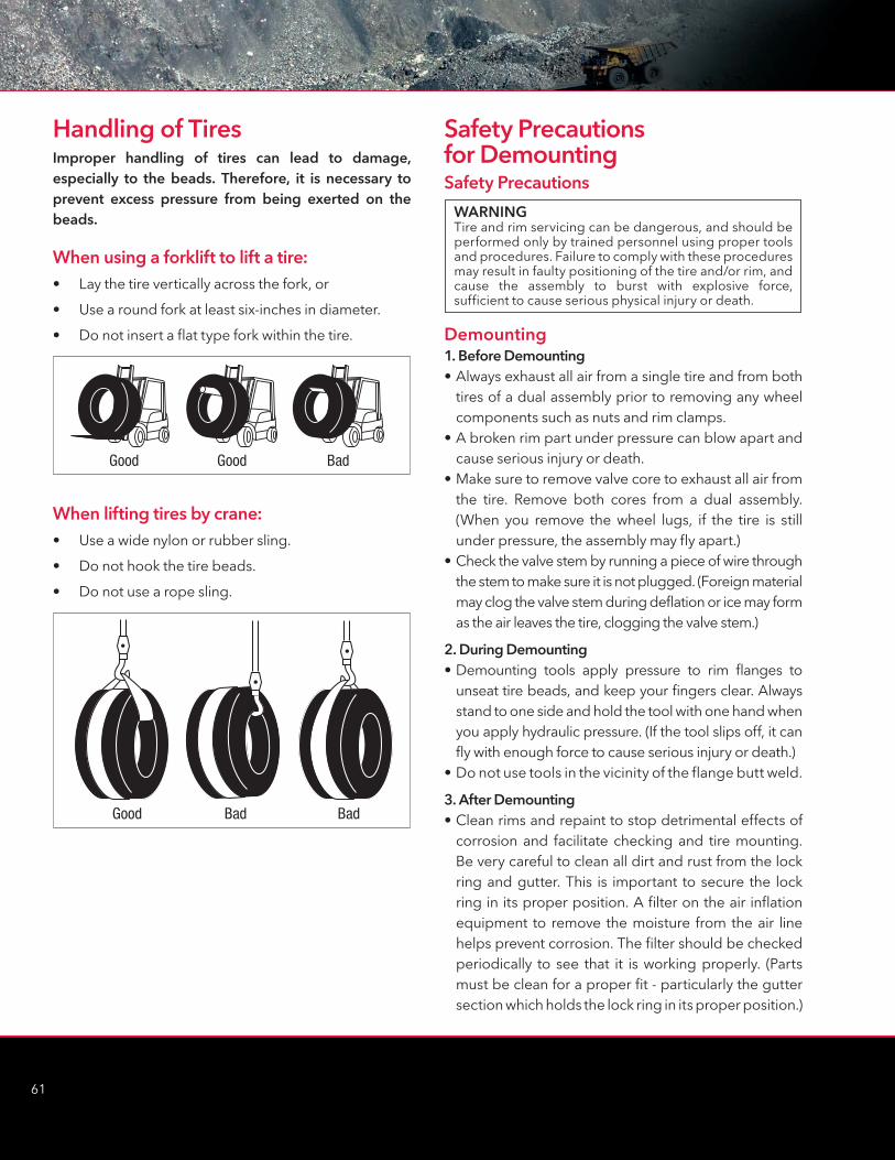
61
Safety Precautions for DemountingSafety Precautions
Demounting1. Before Demounting• Always exhaust all air from a single tire and from both
tires of a dual assembly prior to removing any wheel components such as nuts and rim clamps.
• A broken rim part under pressure can blow apart and cause serious injury or death.
• Make sure to remove valve core to exhaust all air from the tire. Remove both cores from a dual assembly. (When you remove the wheel lugs, if the tire is still under pressure, the assembly may fly apart.)
• Check the valve stem by running a piece of wire through the stem to make sure it is not plugged. (Foreign material may clog the valve stem during deflation or ice may form as the air leaves the tire, clogging the valve stem.)
2. During Demounting• Demounting tools apply pressure to rim flanges to
unseat tire beads, and keep your fingers clear. Always stand to one side and hold the tool with one hand when you apply hydraulic pressure. (If the tool slips off, it can fly with enough force to cause serious injury or death.)
• Do not use tools in the vicinity of the flange butt weld.
3. After Demounting• Clean rims and repaint to stop detrimental effects of
corrosion and facilitate checking and tire mounting. Be very careful to clean all dirt and rust from the lock ring and gutter. This is important to secure the lock ring in its proper position. A filter on the air inflation equipment to remove the moisture from the air line helps prevent corrosion. The filter should be checked periodically to see that it is working properly. (Parts must be clean for a proper fit - particularly the gutter section which holds the lock ring in its proper position.)
Good Bad Bad
WARNINGTire and rim servicing can be dangerous, and should be performed only by trained personnel using proper tools and procedures. Failure to comply with these procedures may result in faulty positioning of the tire and/or rim, and cause the assembly to burst with explosive force, sufficient to cause serious physical injury or death.
Handling of TiresImproper handling of tires can lead to damage, especially to the beads. Therefore, it is necessary to prevent excess pressure from being exerted on the beads.
When using a forklift to lift a tire:• Lay the tire vertically across the fork, or
• Use a round fork at least six-inches in diameter.
• Do not insert a flat type fork within the tire.
When lifting tires by crane:• Use a wide nylon or rubber sling.
• Do not hook the tire beads.
• Do not use a rope sling.
Good Good Bad
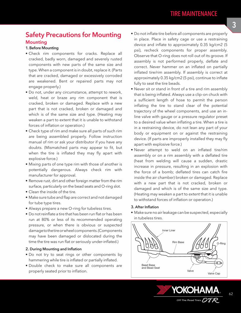
3
62
TIRE MAINTENANCE
Inner Liner
Rim Base
Bead Baseand Bead Seat
O-Ring
Valve CapValve
Safety Precautions for MountingMounting1. Before Mounting• Check rim components for cracks. Replace all
cracked, badly worn, damaged and severely rusted components with new parts of the same size and type. When a component is in doubt, replace it. (Parts that are cracked, damaged or excessively corroded are weakened. Bent or repaired parts may not engage properly.)
• Do not, under any circumstance, attempt to rework, weld, heat or braze any rim component that is cracked, broken or damaged. Replace with a new part that is not cracked, broken or damaged and which is of the same size and type. (Heating may weaken a part to extent that it is unable to withstand forces of inflation or operation.)
• Check type of rim and make sure all parts of such rim are being assembled properly. Follow instruction manual of rim or ask your distributor if you have any doubts. (Mismatched parts may appear to fit, but when the tire is inflated they may fly apart with explosive force.)
• Mixing parts of one type rim with those of another is potentially dangerous. Always check rim with manufacturer for approval.
• Remove rust, dirt and other foreign matter from the rim surface, particularly on the bead seats and O-ring slot.
• Clean the inside of the tire.• Make sure tube and flap are correct and not damaged
for tube type tires.• Always prepare a new O-ring for tubeless tires.• Do not reinflate a tire that has been run flat or has been
run at 80% or less of its recommended operating pressure, or when there is obvious or suspected damage to the tire or wheel components. (Components may have been damaged or dislocated during the time the tire was run flat or seriously under-inflated.)
2. During Mounting and Inflation• Do not try to seat rings or other components by
hammering while tire is inflated or partially inflated.• Double check to make sure all components are
properly seated prior to inflation.
• Do not inflate tire before all components are properly in place. Place in safety cage or use a restraining device and inflate to approximately 0.35 kg/cm2 (5 psi), recheck components for proper assembly. Observe that O-ring does not roll out of its groove. If assembly is not performed properly, deflate and correct. Never hammer on an inflated on partially inflated tire/rim assembly. If assembly is correct at approximately 0.35 kg/cm2 (5 psi), continue to inflate fully to seat the tire beads.
• Never sit or stand in front of a tire and rim assembly that is being inflated. Always use a clip-on chuck with a sufficient length of hose to permit the person inflating the tire to stand clear of the potential trajectory of the wheel components, and use an in-line valve with gauge or a pressure regulator preset to a desired value when inflating a tire. When a tire is in a restraining device, do not lean any part of your body or equipment on or against the restraining device. (If parts are improperly installed they may fly apart with explosive force.)
• Never attempt to weld on an inflated tire/rim assembly or on a rim assembly with a deflated tire (heat from welding will cause a sudden, drastic increase in pressure, resulting in an explosion with the force of a bomb; deflated tires can catch fire inside the air chamber) broken or damaged. Replace with a new part that is not cracked, broken or damaged and which is of the same size and type. (Heating may weaken a part to extent that it is unable to withstand forces of inflation or operation.)
3. After Inflation• Make sure no air leakage can be suspected, especially
in tubeless tires.
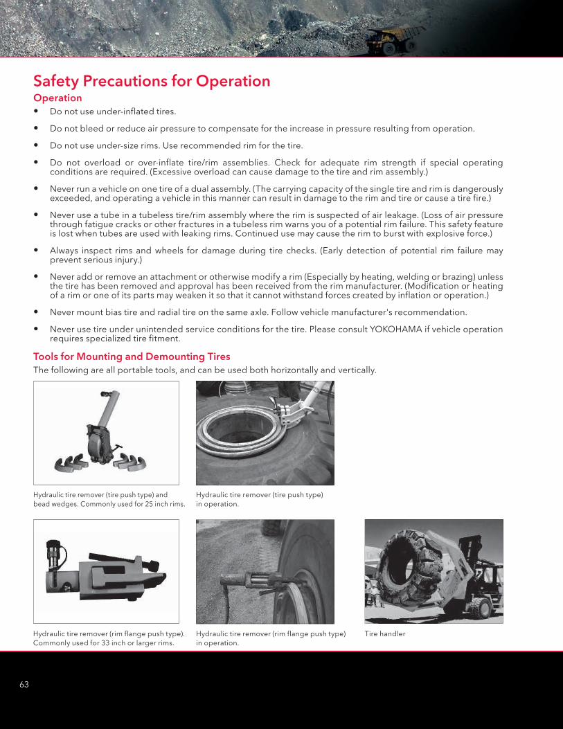
63
Operation• Do not use under-inflated tires.
• Do not bleed or reduce air pressure to compensate for the increase in pressure resulting from operation.
• Do not use under-size rims. Use recommended rim for the tire.
• Do not overload or over-inflate tire/rim assemblies. Check for adequate rim strength if special operating conditions are required. (Excessive overload can cause damage to the tire and rim assembly.)
• Never run a vehicle on one tire of a dual assembly. (The carrying capacity of the single tire and rim is dangerously exceeded, and operating a vehicle in this manner can result in damage to the rim and tire or cause a tire fire.)
• Never use a tube in a tubeless tire/rim assembly where the rim is suspected of air leakage. (Loss of air pressure through fatigue cracks or other fractures in a tubeless rim warns you of a potential rim failure. This safety feature is lost when tubes are used with leaking rims. Continued use may cause the rim to burst with explosive force.)
• Always inspect rims and wheels for damage during tire checks. (Early detection of potential rim failure may prevent serious injury.)
• Never add or remove an attachment or otherwise modify a rim (Especially by heating, welding or brazing) unless the tire has been removed and approval has been received from the rim manufacturer. (Modification or heating of a rim or one of its parts may weaken it so that it cannot withstand forces created by inflation or operation.)
• Never mount bias tire and radial tire on the same axle. Follow vehicle manufacturer's recommendation.
• Never use tire under unintended service conditions for the tire. Please consult YOKOHAMA if vehicle operation requires specialized tire fitment.
Hydraulic tire remover (tire push type) and bead wedges. Commonly used for 25 inch rims.
Hydraulic tire remover (rim flange push type). Commonly used for 33 inch or larger rims.
Hydraulic tire remover (rim flange push type) in operation.
Tire handler
Hydraulic tire remover (tire push type) in operation.
Safety Precautions for Operation
Tools for Mounting and Demounting Tires The following are all portable tools, and can be used both horizontally and vertically.
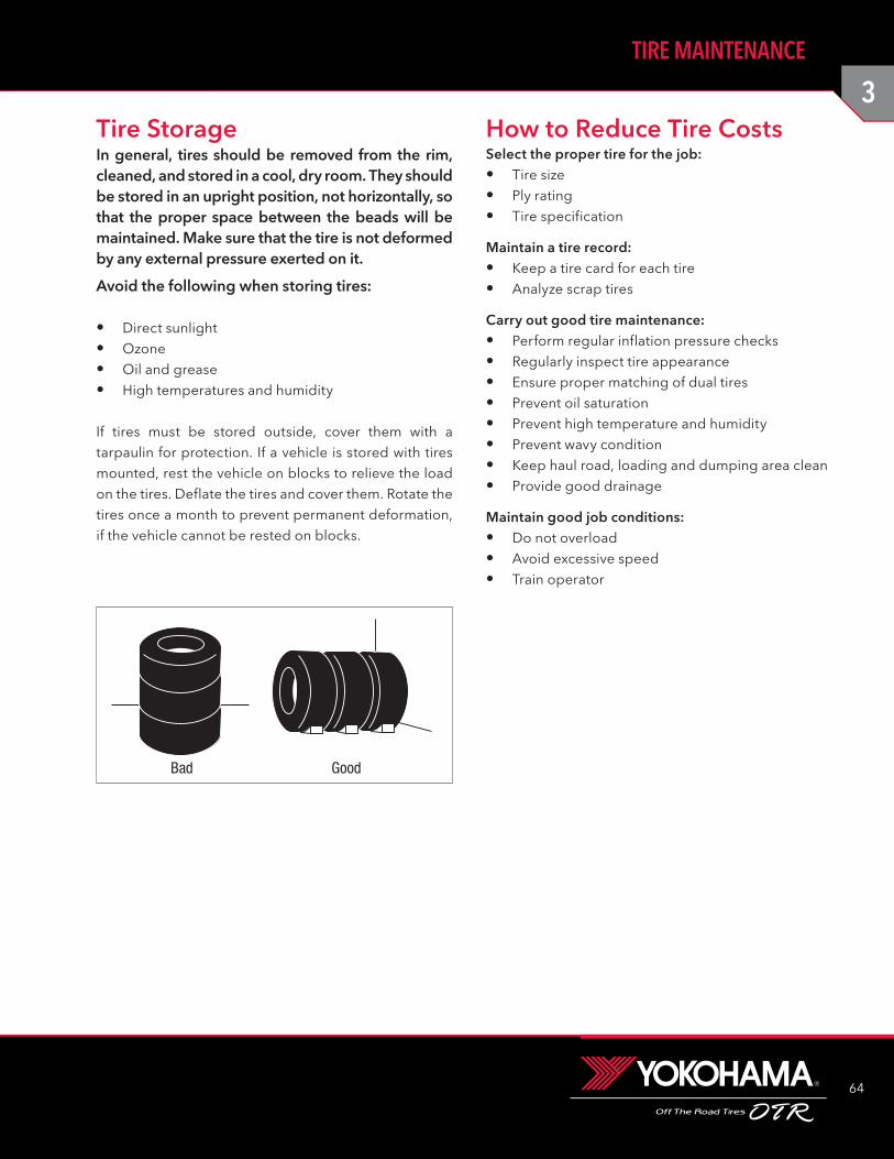
3
64
TIRE MAINTENANCE
Tire Storage�Select the proper tire for the job:• Tire size
• Ply rating
• Tire specification
Maintain a tire record:• Keep a tire card for each tire
• Analyze scrap tires
Carry out good tire maintenance:• Perform regular inflation pressure checks
• Regularly inspect tire appearance
• Ensure proper matching of dual tires
• Prevent oil saturation
• Prevent high temperature and humidity
• Prevent wavy condition
• Keep haul road, loading and dumping area clean
• Provide good drainage
Maintain good job conditions:• Do not overload
• Avoid excessive speed
• Train operator
How to Reduce Tire Costs In general, tires should be removed from the rim, cleaned, and stored in a cool, dry room. They should be stored in an upright position, not horizontally, so that the proper space between the beads will be maintained. Make sure that the tire is not deformed by any external pressure exerted on it.
Avoid the following when storing tires:
• Direct sunlight
• Ozone
• Oil and grease
• High temperatures and humidity
If tires must be stored outside, cover them with a tarpaulin for protection. If a vehicle is stored with tires mounted, rest the vehicle on blocks to relieve the load on the tires. Deflate the tires and cover them. Rotate the tires once a month to prevent permanent deformation, if the vehicle cannot be rested on blocks.
Bad Good
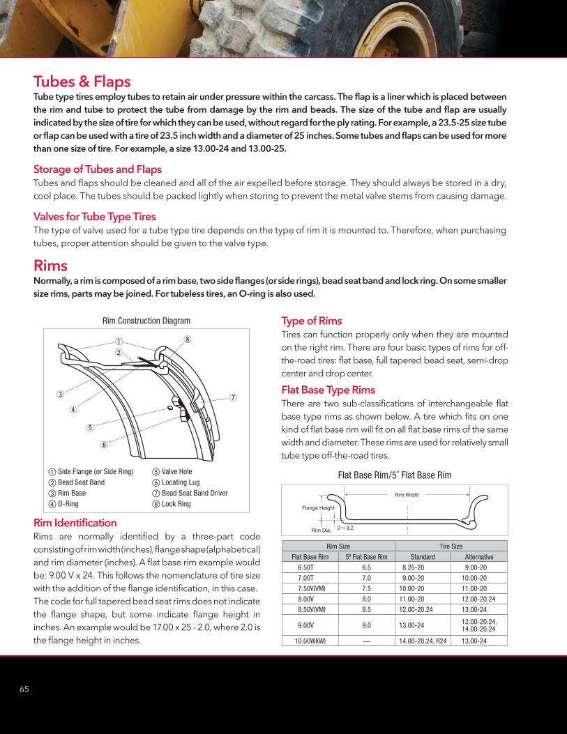
65
Rim Construction Diagram
Side Flange (or Side Ring) Bead Seat Band Rim Base O-Ring
Valve Hole Locating Lug Bead Seat Band Driver Lock Ring
Rim Size Tire Size
Flat Base Rim 5º Flat Base Rim Standard Alternative
6.50T 6.5 8.25-20 9.00-20
7.00T 7.0 9.00-20 10.00-20
7.50V(VM) 7.5 10.00-20 11.00-20
8.00V 8.0 11.00-20 12.00-20.24
8.50V(VM) 8.5 12.00-20.24 13.00-24
9.00V 9.0 13.00-24 12.00-20.24,14.00-20.24
10.00WI(W) — 14.00-20.24, R24 13.00-24
Rim Width
Flange Height
Rim Dia. 2 3.2
Flat Base Rim/5˚ Flat Base Rim
Tubes & FlapsTube type tires employ tubes to retain air under pressure within the carcass. The flap is a liner which is placed between the rim and tube to protect the tube from damage by the rim and beads. The size of the tube and flap are usually indicated by the size of tire for which they can be used, without regard for the ply rating. For example, a 23.5-25 size tube or flap can be used with a tire of 23.5 inch width and a diameter of 25 inches. Some tubes and flaps can be used for more than one size of tire. For example, a size 13.00-24 and 13.00-25.
Storage of Tubes and FlapsTubes and flaps should be cleaned and all of the air expelled before storage. They should always be stored in a dry, cool place. The tubes should be packed lightly when storing to prevent the metal valve stems from causing damage.
Valves for Tube Type TiresThe type of valve used for a tube type tire depends on the type of rim it is mounted to. Therefore, when purchasing tubes, proper attention should be given to the valve type.
RimsNormally, a rim is composed of a rim base, two side flanges (or side rings), bead seat band and lock ring. On some smaller size rims, parts may be joined. For tubeless tires, an O-ring is also used.
Rim IdentificationRims are normally identified by a three-part code consisting of rim width (inches), flange shape (alphabetical) and rim diameter (inches). A flat base rim example would be: 9.00 V x 24. This follows the nomenclature of tire size with the addition of the flange identification, in this case.The code for full tapered bead seat rims does not indicate the flange shape, but some indicate flange height in inches. An example would be 17.00 x 25 - 2.0, where 2.0 is the flange height in inches.
Type of RimsTires can function properly only when they are mounted on the right rim. There are four basic types of rims for off-the-road tires: flat base, full tapered bead seat, semi-drop center and drop center.
Flat Base Type RimsThere are two sub-classifications of interchangeable flat base type rims as shown below. A tire which fits on one kind of flat base rim will fit on all flat base rims of the same width and diameter. These rims are used for relatively small tube type off-the-road tires.
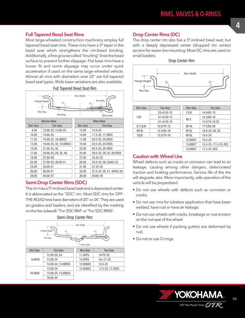
4
66
RIMS, VALVES & O-RINGS
Drop Center Rims (DC)The drop center rim also has a 5º-inclined bead seat, but with a deeply depressed center (dropped rim center) section for easier tire mounting. Most DC rims are used on small loaders.
Caution with Wheel UseWheel defects such as cracks or corrosion can lead to air leakage, causing among other dangers, deteriorated traction and braking performance. Service life of the tire will degrade, also. More importantly, safe operation of the vehicle will be jeopardized.
• Do not use wheels with defects such as corrosion or cracks.
• Do not use rims for tubeless application that have been welded, have rust or have air leakage.
• Do not use wheels with cracks, breakage or rust erosion on the nut seat of the wheel.
• Do not use wheels if packing gutters are deformed by rust.
• Do not re-use O-rings.
Full Tapered Bead Seat RimsMost large-wheeled construction machinery employ full tapered bead seat rims. These rims have a 5º taper in the bead seat which strengthens the rim/bead binding. Additionally, a fine groove called "knurling" lines the bead surface to prevent further slippage. Flat base rims have a looser fit and some slippage may occur under quick acceleration if used on the same large-wheeled vehicle. Almost all rims with diameters over 25" are full tapered bead seat types. Wide base variations are also available.
Semi-Drop Center Rims (SDC)This rim has a 5º-inclined bead seat and a depressed center. It is abbreviated as the "SDC" rim. Most SDC rims for OFF-THE-ROAD tires have diameters of 20" or 24". They are used on graders and loaders, and are identified by the marking on the tire sidewall: "For SDC RIM" or "For SDC RIMS".
Rim Width
5˚ 5˚Flange Height
Rim Dia.
Valve Hole
Knurling
Knurling
Full Tapered Bead Seat Rim
Narrow Base
Rim Size Tire Size
8.50 12.00-25, 13.00-25
10.00 14.00-25
11.25 16.00-25, 16.00R25
13.00 18.00-25, 33, 18.00R33
15.00 21.00-25, 35
17.00 24.00-25, 29, 35, 49
19.50 27.00-49
22.00 27.00-33, 30.00-51
24.00 33.00-51
26.00 36.00-51
29.00 40.00-57
Wide Base
Rim Size Tire Size
12.00 15.5-25
14.00 17.5-25, 17.5R25
17.00 20.5-25, 20.5R25
19.50 23.5-25, 23.5R25
22.00 26.5-25, 26.5R25
25.00 29.5-25, 29, 35, 29.5R25
27.00 33.25-35
28.00 33.5-33, 39, 35/65-33
31.00 37.25-35
32.00 37.5-33, 39, 51, 40/65-39
36.00 45/65-45
Rim Width
Valve Hole
Flange Height
Rim Dia.
5˚ 5˚
Semi-Drop Center Rim
Rim Size Tire Size
8.00TG
12.00-20, 24
13.00-24
14.00-24, 14.00R24
10.00VA
13.00-24
14.00-24, 14.00R24
16.00-24
Rim Size Tire Size
11.00TG 14/70-20
14.00TG 42×17-20
12.00SDC 15.5-25
14.00SDC 17.5-25, 17.5R25
Rim Width
Flange Height
Rim Dia.
5˚ 5˚
Drop Center Rim
Rim Size Tire Size
7JA
23×8.50-12
27×8.50-15
27×9.50-15
8-1/2JA 10.0/70-12
W10L 12.5/65-18
10LB 12.5/70-16
Rim Size Tire Size
11LB 14.0/65-15
W1315.5/60-18
15.5/70-18.20
W14L 17.5/65-20
W15L 16.9-24, 28, 30
W16L 18.4-24
12.00DC* 15.5-25
13.00DC* 15.5-25, 17.5-25, R25
14.00DC* 17.5-25, R25
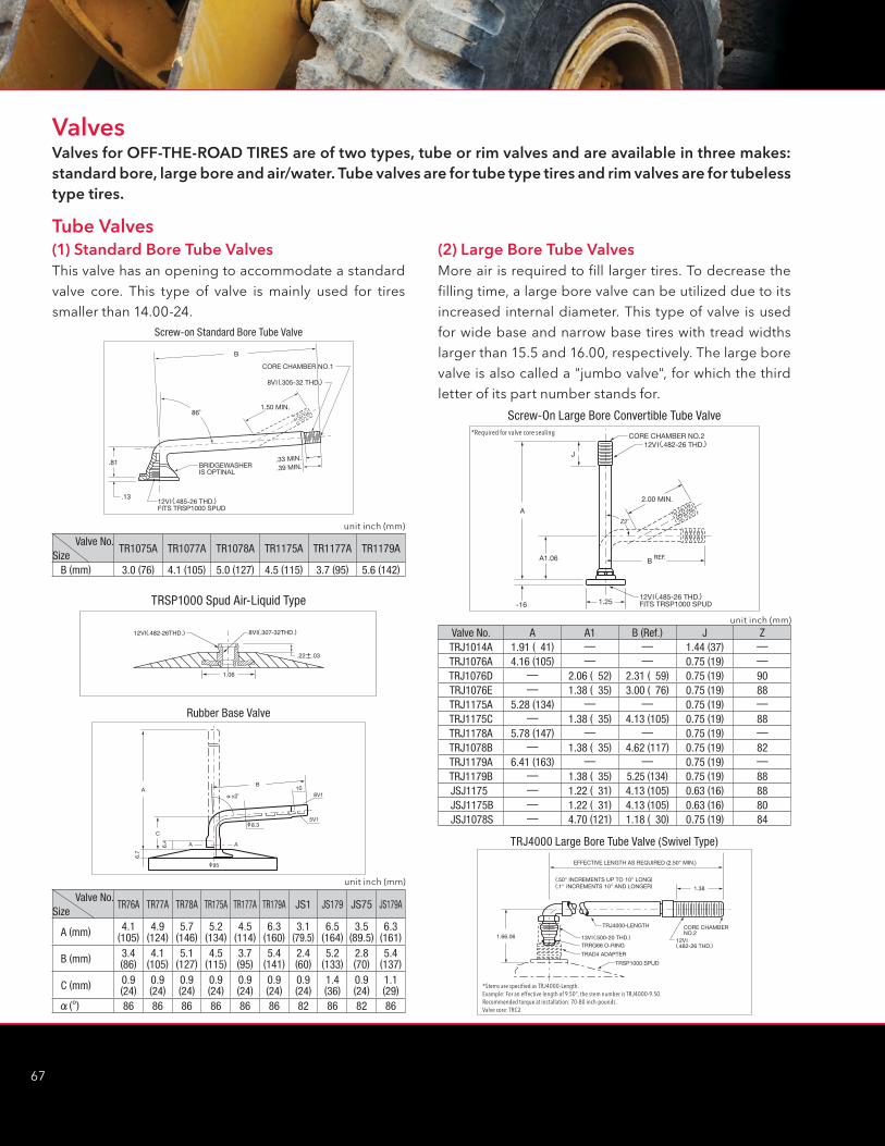
67
(1) Standard Bore Tube ValvesThis valve has an opening to accommodate a standard valve core. This type of valve is mainly used for tires smaller than 14.00-24.
Tube Valves
Valves
CORE CHAMBER NO.1
1.50 MIN.
.81
.13
86˚
B
BRIDGEWASHERIS OPTINAL
12VI (.485-26 THD.)FITS TRSP1000 SPUD
.33 MIN.
.39 MIN.
8VI (.305-32 THD.)
Screw-on Standard Bore Tube Valve
±2˚
8.3
95
A
8V110
5V1
A
C
B
6.4
6.7
A
Rubber Base Valve
(2) Large Bore Tube ValvesMore air is required to fill larger tires. To decrease the filling time, a large bore valve can be utilized due to its increased internal diameter. This type of valve is used for wide base and narrow base tires with tread widths larger than 15.5 and 16.00, respectively. The large bore valve is also called a "jumbo valve", for which the third letter of its part number stands for.
CORE CHAMBER NO.2
2.00 MIN.
J
A
BREF.
1.25-16
A1.06
Z2˚
12VI (.485-26 THD.)FITS TRSP1000 SPUD
12VI (.482-26 THD.)
Screw-On Large Bore Convertible Tube Valve*Required for valve core sealing
1.66.06 13VI (.500-20 THD.) 12VI(.482-26 THD.)TRRG66 O-RING
TRAD4 ADAPTER
TRJ4000-LENGTH
EFFECTIVE LENGTH AS REQUIRED (2.50" MIN.)
1.38
TRSP1000 SPUD
(.50" INCREMENTS UP TO 10" LONG)(.1" INCREMENTS 10" AND LONGER)
CORE CHAMBERNO.2
TRJ4000 Large Bore Tube Valve (Swivel Type)
*Stems are specified as TRJ4000-Length.Example: For an effective length of 9.50", the stem number is TRJ4000-9.50.Recommended torque at installation: 70-80 inch-pounds.Valve core: TRC2
unit inch (mm)
Valve No.TR76A TR77A TR78A TR175A TR177A TR179A JS1 JS179 JS75 JS179A
Size
A (mm) 4.1 (105)
4.9 (124)
5.7 (146)
5.2 (134)
4.5 (114)
6.3 (160)
3.1 (79.5)
6.5 (164)
3.5 (89.5)
6.3 (161)
B (mm) 3.4 (86)
4.1 (105)
5.1 (127)
4.5 (115)
3.7 (95)
5.4 (141)
2.4 (60)
5.2 (133)
2.8 (70)
5.4 (137)
C (mm) 0.9 (24)
0.9 (24)
0.9 (24)
0.9 (24)
0.9 (24)
0.9 (24)
0.9 (24)
1.4 (36)
0.9 (24)
1.1 (29)
(°) 86 86 86 86 86 86 82 86 82 86
Valve No.TR1075A TR1077A TR1078A TR1175A TR1177A TR1179A
SizeB (mm) 3.0 (76) 4.1 (105) 5.0 (127) 4.5 (115) 3.7 (95) 5.6 (142)
unit inch (mm)
8VI(.307-32THD.)
1.06
12VI(.482-26THD.)
TRSP1000 Spud Air-Liquid Type
Valve No. A A1 B (Ref.) J ZTRJ1014A 1.91 ( 41) — — 1.44 (37) —TRJ1076A 4.16 (105) — — 0.75 (19) —TRJ1076D — 2.06 ( 52) 2.31 ( 59) 0.75 (19) 90TRJ1076E — 1.38 ( 35) 3.00 ( 76) 0.75 (19) 88TRJ1175A 5.28 (134) — — 0.75 (19) —TRJ1175C — 1.38 ( 35) 4.13 (105) 0.75 (19) 88TRJ1178A 5.78 (147) — — 0.75 (19) —TRJ1078B — 1.38 ( 35) 4.62 (117) 0.75 (19) 82TRJ1179A 6.41 (163) — — 0.75 (19) —TRJ1179B — 1.38 ( 35) 5.25 (134) 0.75 (19) 88JSJ1175 — 1.22 ( 31) 4.13 (105) 0.63 (16) 88JSJ1175B — 1.22 ( 31) 4.13 (105) 0.63 (16) 80JSJ1078S — 4.70 (121) 1.18 ( 30) 0.75 (19) 84
unit inch (mm)
Valves for OFF-THE-ROAD TIRES are of two types, tube or rim valves and are available in three makes: standard bore, large bore and air/water. Tube valves are for tube type tires and rim valves are for tubeless type tires.
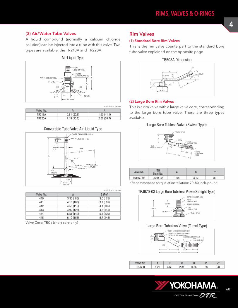
4
68
RIMS, VALVES & O-RINGS
Rim Valves(3) Air/Water Tube ValvesA liquid compound (normally a calcium chloride solution) can be injected into a tube with this valve. Two types are available, the TR218A and TR220A.
8.3VI
TRCH3CORE HOUSING
(.305-32 THD.)
12V1(.482-26 THD.) A
SPUO
.38
TR LNIO
.64
.81
.313
.317
A1
Air-Liquid Type
8V1(.305-32 THD.)
CORE CHAMBER NO.3
A
B
REF.
±1.5˚85˚
DIA.
0.6(15±1)
.33 MIN. (8.4)
.305 DIA. (7.7)
.875 (22.23)
Convertible Tube Valve Air-Liquid Type
(1) Standard Bore Rim ValvesThis is the rim valve counterpart to the standard bore tube valve explained on the opposite page.
(2) Large Bore Rim ValvesThis is a rim valve with a large valve core, corresponding to the large bore tube valve. There are three types available.
90˚±2˚25˚±2˚
38
42
10
16V1
8V1
5V1
7.8
17.5
10
4
28.5
TR503A Dimension
STEM
1.38
BP2.
CORECHAMBERNO.2
12V1(.482-26 THD)
13V1(.500-20 THD)
TRSP2 SPUD
A
Z
Large Bore Tubless Valve (Swivel Type)
Valve No. *TRStem No. A B Zº
TRJ650-03 J650-02 1.08 3.12 80
12V1(.482-26 THD)
13V1(.500-20 THD)
.69MIN
CORE CHAMBER NO.2
TRJ670-02 STEM
TRSP2 SPUD
1.630.3
.50 HEX.
TRJ670-03 Large Bore Tubeless Valve (Straight Type)
12V1(.482-26 THD)
CORE CHAMBER NO.2
TRLS7 LOCK SCREW (.94 HEX)
TRRG16 RUBBER GROMMETFITS .812 DIA VALVE HOLE
D REF.
1.38Y
A06
CRD.
BRD.
Z.50
Large Bore Tubeless Valve (Turret Type)
Valve No. A B C D Yº ZºTRJ690 1.25 4.69 2.31 0.56 28 28
Valve No. A1 ATR218A 0.81 (20.6) 1.63 (41.1)TR220A 1.19 (30.2) 2.00 (50.7)
unit inch (mm)
Valve No. A B (Ref)440 3.35 ( 85) 3.0 ( 75)441 4.13 (105) 3.7 ( 95)442 4.53 (115) 4.1 (105)443 4.92 (125) 4.5 (115)444 5.51 (140) 5.1 (130)445 6.10 (155) 5.7 (145)
Valve Core: TRCa (short core only)
unit inch (mm)
* Recommended torque at installation: 70-80 inch-pound
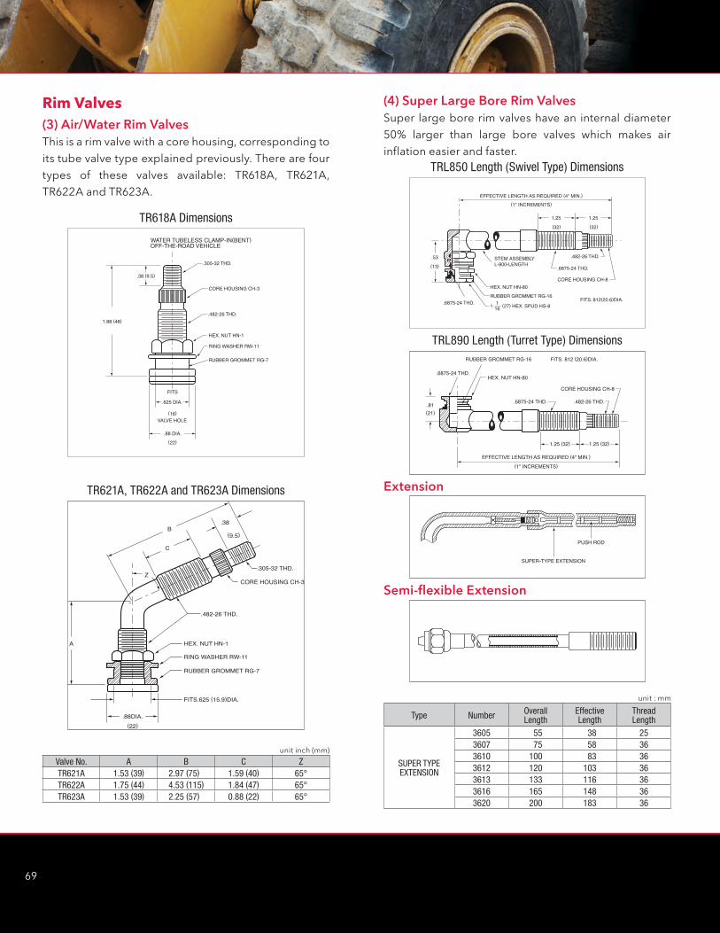
69
(4) Super Large Bore Rim ValvesSuper large bore rim valves have an internal diameter 50% larger than large bore valves which makes air inflation easier and faster.
TRL850 Length (Swivel Type) Dimensions
(1" INCREMENTS)EFFECTIVE LENGTH AS REQUIRED (4" MIN.)
(21).81 .6875-24 THD. .482-26 THD.
.6875-24 THD.
FITS. 812 (20.6)DIA.
HEX. NUT HN-80
RUBBER GROMMET RG-16
CORE HOUSING CH-8
1.25 (32) 1.25 (32)
TRL890 Length (Turret Type) Dimensions
Extension
PUSH ROD
SUPER-TYPE EXTENSION
Semi-flexible Extension
Type Number Overall Length
Effective Length
Thread Length
SUPER TYPE EXTENSION
3605 55 38 253607 75 58 363610 100 83 363612 120 103 363613 133 116 363616 165 148 363620 200 183 36
unit : mm
(3) Air/Water Rim ValvesThis is a rim valve with a core housing, corresponding to its tube valve type explained previously. There are four types of these valves available: TR618A, TR621A, TR622A and TR623A.
TR618A Dimensions
(9.5)B
C
.38
.305-32 THD.
.482-26 THD.
HEX. NUT HN-1
RING WASHER RW-11
RUBBER GROMMET RG-7
FITS.625 (15.9)DIA.
.88DIA.
A
Z
(22)
CORE HOUSING CH-3
TR621A, TR622A and TR623A Dimensions
Valve No. A B C ZTR621A 1.53 (39) 2.97 (75) 1.59 (40) 65°TR622A 1.75 (44) 4.53 (115) 1.84 (47) 65°TR623A 1.53 (39) 2.25 (57) 0.88 (22) 65°
unit inch (mm)
Rim Valves

4
70
RIMS, VALVES & O-RINGS
Valve Classification by Rim TypeType of Rim Tire Width Tube Type Tubeless
FLAT BASE TYPE 14.00 and Under16.00 and Over
Standard Bore Tube ValveLarge Bore Tube Valve
Standard Bore Rim ValveLarge Bore Rim Valve
FULL TAPERED14.00 and Under16.00 and Over15.5 and Over
Standard Bore Tube ValveLarge Bore Tube ValveLarge Bore Tube Valve
Standard Bore Rim ValveLarge Bore Rim ValveLarge/Super Large Bore Rim Valve
SEMI-DROP CENTER All Sizes Standard Bore Tube ValveAir/Water Tube Valve Air/Water Rim Valve
DROP CENTER All Sizes Air/Water Tube Valve Air/Water Rim Valve
(5) Caution with Tubeless Air ValvesWhenever the tubeless tire is demounted and changed, the tubeless air valve (rim valve) must be replaced with a new one, regardless of appearance.
NOTES: Valves for inside dual-pair tire are equipped with a supplemental valve extension to facilitate air inflation. The extension is made of brass which is apt to nicks, scratches and dents. Care is required when (de)mounting, and storage should be in a clean, moisture free area.
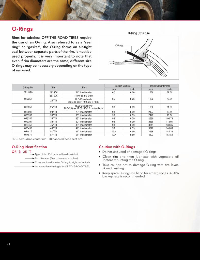
71
Rims for tubeless OFF-THE-ROAD TIRES require the use of an O-ring. Also referred to as a "seal ring" or "gasket", the O-ring forms an air-tight seal between separate parts of the rim. It must be used properly. It is very important to note that even if rim diameters are the same, different size O-rings may be necessary depending on the type of rim used.
O-Rings
O-Ring
O-Ring Structure
O-Ring No. Rim TireSection Diameter Inside Circumference
mm inch mm inchOR224TG 24” SDC 24” rim diameter 6.7 0.26 1768 69.61
OR225T25” SDC 14.00-25 and under
6.7 0.26 1802 70.9425” TB 17.5-25 and under
20.5-25 (use 17.00×25-1.7 rim)
OR325T 25” TB 16.00-25 and over 20.5-25 (use 17.00×25-2.0 rim) and over 9.8 0.39 1800 71.06
OR329T 29” TB 29” rim diameter 9.8 0.39 2127 83.74OR333T 33” TB 33” rim diameter 9.8 0.39 2447 96.34OR335T 35” TB 35” rim diameter 9.8 0.39 2560 100.79OR339T 39” TB 39” rim diameter 9.8 0.39 2868 112.91OR345T 45” TB 45” rim diameter 9.8 0.39 3311 130.35OR349T 49” TB 49” rim diameter 9.8 0.39 3572 140.63OR451T 51” TB 51” rim diameter 12.7 0.50 3666 144.33OR457T 57” TB 57” rim diameter 12.7 0.50 4103 161.54
SDC: semi-drop center rim TB: tapered bead seat rim
O-Ring identificationOR 3 25 T
Type of rim (Full tapered bead seat rim)
Rim diameter (Bead diameter in inches)
Cross section diameter O-ring (in eights of an inch)
Indicates that the ring is for OFF-THE-ROAD TIRES
Caution with O-Ringsl���Do not use used or damaged O-rings.�
l� Clean rim and then lubricate with vegetable oil before mounting the O-ring.�
l� Take caution not to damage O-ring with tire lever. Avoid twisting.�
l���Keep spare O-rings on hand for emergencies. A 20% backup rate is recommended.
4
72
RIMS, VALVES & O-RINGS
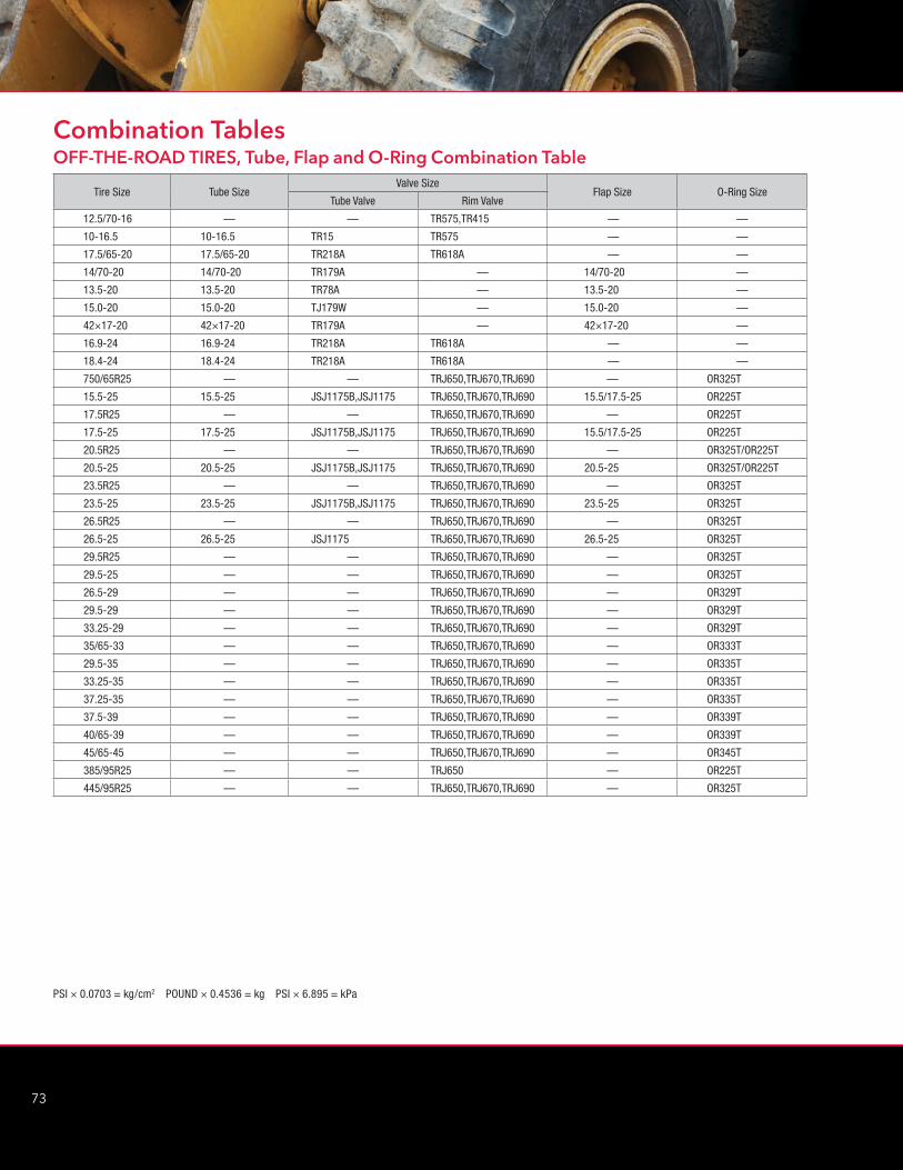
73
PSI × 0.0703 = kg/cm2 POUND × 0.4536 = kg PSI × 6.895 = kPa
OFF-THE-ROAD TIRES, Tube, Flap and O-Ring Combination Table
Tire Size Tube SizeValve Size
Flap Size O-Ring SizeTube Valve Rim Valve
12.5/70-16 — — TR575,TR415 — —
10-16.5 10-16.5 TR15 TR575 — —
17.5/65-20 17.5/65-20 TR218A TR618A — —
14/70-20 14/70-20 TR179A — 14/70-20 —
13.5-20 13.5-20 TR78A — 13.5-20 —
15.0-20 15.0-20 TJ179W — 15.0-20 —
42×17-20 42×17-20 TR179A — 42×17-20 —
16.9-24 16.9-24 TR218A TR618A — —
18.4-24 18.4-24 TR218A TR618A — —
750/65R25 — — TRJ650,TRJ670,TRJ690 — OR325T
15.5-25 15.5-25 JSJ1175B,JSJ1175 TRJ650,TRJ670,TRJ690 15.5/17.5-25 OR225T
17.5R25 — — TRJ650,TRJ670,TRJ690 — OR225T
17.5-25 17.5-25 JSJ1175B,JSJ1175 TRJ650,TRJ670,TRJ690 15.5/17.5-25 OR225T
20.5R25 — — TRJ650,TRJ670,TRJ690 — OR325T/OR225T
20.5-25 20.5-25 JSJ1175B,JSJ1175 TRJ650,TRJ670,TRJ690 20.5-25 OR325T/OR225T
23.5R25 — — TRJ650,TRJ670,TRJ690 — OR325T
23.5-25 23.5-25 JSJ1175B,JSJ1175 TRJ650,TRJ670,TRJ690 23.5-25 OR325T
26.5R25 — — TRJ650,TRJ670,TRJ690 — OR325T
26.5-25 26.5-25 JSJ1175 TRJ650,TRJ670,TRJ690 26.5-25 OR325T
29.5R25 — — TRJ650,TRJ670,TRJ690 — OR325T
29.5-25 — — TRJ650,TRJ670,TRJ690 — OR325T
26.5-29 — — TRJ650,TRJ670,TRJ690 — OR329T
29.5-29 — — TRJ650,TRJ670,TRJ690 — OR329T
33.25-29 — — TRJ650,TRJ670,TRJ690 — OR329T
35/65-33 — — TRJ650,TRJ670,TRJ690 — OR333T
29.5-35 — — TRJ650,TRJ670,TRJ690 — OR335T
33.25-35 — — TRJ650,TRJ670,TRJ690 — OR335T
37.25-35 — — TRJ650,TRJ670,TRJ690 — OR335T
37.5-39 — — TRJ650,TRJ670,TRJ690 — OR339T
40/65-39 — — TRJ650,TRJ670,TRJ690 — OR339T
45/65-45 — — TRJ650,TRJ670,TRJ690 — OR345T
385/95R25 — — TRJ650 — OR225T
445/95R25 — — TRJ650,TRJ670,TRJ690 — OR325T
Combination Tables
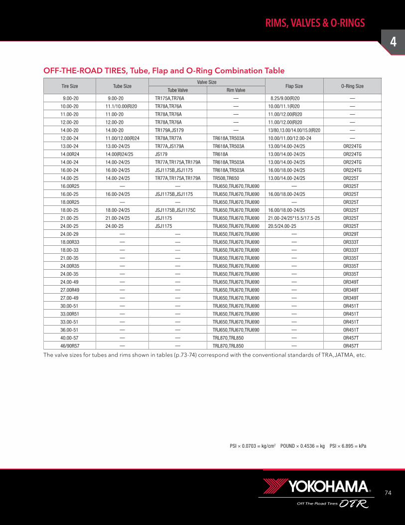
4
74
RIMS, VALVES & O-RINGS
PSI × 0.0703 = kg/cm2 POUND × 0.4536 = kg PSI × 6.895 = kPa
OFF-THE-ROAD TIRES, Tube, Flap and O-Ring Combination Table
Tire Size Tube SizeValve Size
Flap Size O-Ring SizeTube Valve Rim Valve
9.00-20 9.00-20 TR175A,TR76A — 8.25/9.00(R)20 —
10.00-20 11.1/10.00(R)20 TR78A,TR76A — 10.00/11.1(R)20 —
11.00-20 11.00-20 TR78A,TR76A — 11.00/12.00(R)20 —
12.00-20 12.00-20 TR78A,TR76A — 11.00/12.00(R)20 —
14.00-20 14.00-20 TR179A,JS179 — 13/80,13.00/14.00/15.0(R)20 —
12.00-24 11.00/12.00(R)24 TR78A,TR77A TR618A,TR503A 10.00/11.00/12.00-24 —
13.00-24 13.00-24/25 TR77A,JS179A TR618A,TR503A 13.00/14.00-24/25 OR224TG
14.00R24 14.00(R)24/25 JS179 TR618A 13.00/14.00-24/25 OR224TG
14.00-24 14.00-24/25 TR77A,TR175A,TR179A TR618A,TR503A 13.00/14.00-24/25 OR224TG
16.00-24 16.00-24/25 JSJ1175B,JSJ1175 TR618A,TR503A 16.00/18.00-24/25 OR224TG
14.00-25 14.00-24/25 TR77A,TR175A,TR179A TR508,TR650 13.00/14.00-24/25 OR225T
16.00R25 — — TRJ650,TRJ670,TRJ690 — OR325T
16.00-25 16.00-24/25 JSJ1175B,JSJ1175 TRJ650,TRJ670,TRJ690 16.00/18.00-24/25 OR325T
18.00R25 — — TRJ650,TRJ670,TRJ690 — OR325T
18.00-25 18.00-24/25 JSJ1175B,JSJ1175C TRJ650,TRJ670,TRJ690 16.00/18.00-24/25 OR325T
21.00-25 21.00-24/25 JSJ1175 TRJ650,TRJ670,TRJ690 21.00-24/25*15.5/17.5-25 OR325T
24.00-25 24.00-25 JSJ1175 TRJ650,TRJ670,TRJ690 20.5/24.00-25 OR325T
24.00-29 — — TRJ650,TRJ670,TRJ690 — OR329T
18.00R33 — — TRJ650,TRJ670,TRJ690 — OR333T
18.00-33 — — TRJ650,TRJ670,TRJ690 — OR333T
21.00-35 — — TRJ650,TRJ670,TRJ690 — OR335T
24.00R35 — — TRJ650,TRJ670,TRJ690 — OR335T
24.00-35 — — TRJ650,TRJ670,TRJ690 — OR335T
24.00-49 — — TRJ650,TRJ670,TRJ690 — OR349T
27.00R49 — — TRJ650,TRJ670,TRJ690 — OR349T
27.00-49 — — TRJ650,TRJ670,TRJ690 — OR349T
30.00-51 — — TRJ650,TRJ670,TRJ690 — OR451T
33.00R51 — — TRJ650,TRJ670,TRJ690 — OR451T
33.00-51 — — TRJ650,TRJ670,TRJ690 — OR451T
36.00-51 — — TRJ650,TRJ670,TRJ690 — OR451T
40.00-57 — — TRL870,TRL850 — OR457T
46/90R57 — — TRL870,TRL850 — OR457T
The valve sizes for tubes and rims shown in tables (p.73-74) correspond with the conventional standards of TRA,JATMA, etc.
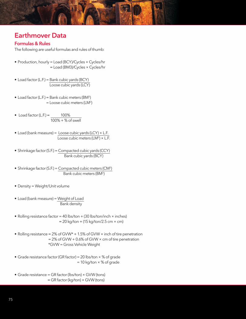
75
Earthmover DataFormulas & RulesThe following are useful formulas and rules of thumb:
• Production, hourly = Load (BCY)/Cycles × Cycles/hr = Load (BM3)/Cycles × Cycles/hr
• Load factor (L.F.) = Bank cubic yards (BCY) Loose cubic yards (LCY)
• Load factor (L.F.) = Bank cubic meters (BM3) = Loose cubic meters (LM3)
• Load factor (L.F.) = 100% 100% + % of swell
• Load (bank measure) = Loose cubic yards (LCY) × L.F. Loose cubic meters (LM3) × L.F.
• Shrinkage factor (S.F.) = Compacted cubic yards (CCY) Bank cubic yards (BCY)
• Shrinkage factor (S.F.) = Compacted cubic meters (CM3) Bank cubic meters (BM3)
• Density = Weight/Unit volume
• Load (bank measure) = Weight of Load Bank density
• Rolling resistance factor = 40 lbs/ton + (30 lbs/ton/inch × inches) = 20 kg/ton + (15 kg/ton/2.5 cm × cm)
• Rolling resistance = 2% of GVW* + 1.5% of GVW × inch of tire penetration = 2% of GVW + 0.6% of GVW × cm of tire penetration *GVW = Gross Vehicle Weight
• Grade resistance factor (GR factor) = 20 lbs/ton × % of grade = 10 kg/ton × % of grade
• Grade resistance = GR factor (lbs/ton) × GVW (tons) = GR factor (kg/ton) × GVW (tons)
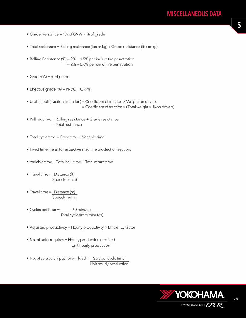
5
76
MISCELLANEOUS DATA
• Grade resistance = 1% of GVW × % of grade
• Total resistance = Rolling resistance (lbs or kg) + Grade resistance (lbs or kg)
• Rolling Resistance (%) = 2% + 1.5% per inch of tire penetration = 2% + 0.6% per cm of tire penetration
• Grade (%) = % of grade
• Effective grade (%) = PR (%) + GR (%)
• Usable pull (traction limitation) = Coefficient of traction × Weight on drivers = Coefficient of traction × (Total weight × % on drivers)
• Pull required = Rolling resistance + Grade resistance = Total resistance
• Total cycle time = Fixed time + Variable time
• Fixed time: Refer to respective machine production section.
• Variable time = Total haul time + Total return time
• Travel time = Distance (ft) Speed (ft/min)
• Travel time = Distance (m) Speed (m/min)
• Cycles per hour = 60 minutes Total cycle time (minutes)
• Adjusted productivity = Hourly productivity × Efficiency factor
• No. of units requires = Hourly production required Unit hourly production
• No. of scrapers a pusher will load = Scraper cycle time Unit hourly production
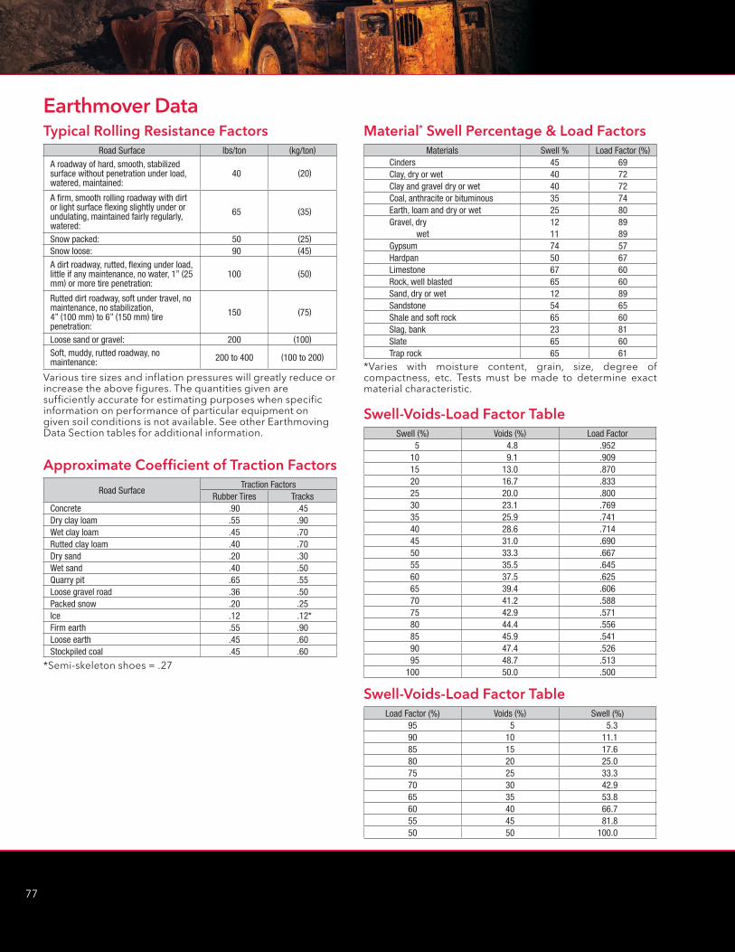
77
Typical Rolling Resistance FactorsRoad Surface lbs/ton (kg/ton)
A roadway of hard, smooth, stabilized surface without penetration under load, watered, maintained:
40 (20)
A firm, smooth rolling roadway with dirt or light surface flexing slightly under or undulating, maintained fairly regularly, watered:
65 (35)
Snow packed: 50 (25)Snow loose: 90 (45)
A dirt roadway, rutted, flexing under load, little if any maintenance, no water, 1” (25 mm) or more tire penetration:
100 (50)
Rutted dirt roadway, soft under travel, no maintenance, no stabilization, 4” (100 mm) to 6” (150 mm) tire penetration:
150 (75)
Loose sand or gravel: 200 (100)
Soft, muddy, rutted roadway, no maintenance: 200 to 400 (100 to 200)
Various tire sizes and inflation pressures will greatly reduce or increase the above figures. The quantities given are sufficiently accurate for estimating purposes when specific information on performance of particular equipment on given soil conditions is not available. See other Earthmoving Data Section tables for additional information.
Approximate Coefficient of Traction Factors
Road SurfaceTraction Factors
Rubber Tires TracksConcrete .90 .45 Dry clay loam .55 .90 Wet clay loam .45 .70 Rutted clay loam .40 .70 Dry sand .20 .30 Wet sand .40 .50 Quarry pit .65 .55 Loose gravel road .36 .50 Packed snow .20 .25 Ice .12 .12*Firm earth .55 .90 Loose earth .45 .60 Stockpiled coal .45 .60
*Semi-skeleton shoes = .27
Material* Swell Percentage & Load FactorsMaterials Swell % Load Factor (%)
Cinders 45 69Clay, dry or wet 40 72Clay and gravel dry or wet 40 72Coal, anthracite or bituminous 35 74Earth, loam and dry or wet 25 80Gravel, dry 12 89 wet 11 89Gypsum 74 57Hardpan 50 67Limestone 67 60Rock, well blasted 65 60Sand, dry or wet 12 89Sandstone 54 65Shale and soft rock 65 60Slag, bank 23 81Slate 65 60Trap rock 65 61
Swell-Voids-Load Factor TableSwell (%) Voids (%) Load Factor
5 4.8 .952 10 9.1 .909 15 13.0 .870 20 16.7 .833 25 20.0 .800 30 23.1 .769 35 25.9 .741 40 28.6 .714 45 31.0 .690 50 33.3 .667 55 35.5 .645 60 37.5 .625 65 39.4 .606 70 41.2 .588 75 42.9 .571 80 44.4 .556 85 45.9 .541 90 47.4 .526 95 48.7 .513
100 50.0 .500
Swell-Voids-Load Factor TableLoad Factor (%) Voids (%) Swell (%)
95 5 5.3 90 10 11.1 85 15 17.6 80 20 25.0 75 25 33.3 70 30 42.9 65 35 53.8 60 40 66.7 55 45 81.8 50 50 100.0
*Varies with moisture content, grain, size, degree of compactness, etc. Tests must be made to determine exact material characteristic.
Earthmover Data
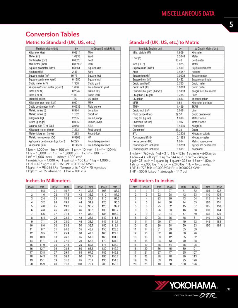
5
78
MISCELLANEOUS DATA
Metric to Standard (UK, US, etc.) Multiply Metric Unit by to Obtain English Unit
Kilometer (km) 0.6214 MileMeter (m) 1.0936 YardCentimeter (cm) 0.0328 FootMillimeter (mm) 0.03937 InchSquare Kilometer (km2) 0.3861 Square MileHectare (Ha) 2.471 AcreSquare meter (m2) 10.76 Square footSquare centimeter (cm2) 0.1550 Square inchCubic meter (m3) 1.308 Cubic yardkilograms/cubic meter (kg/m3) 1.686 Pounds/cubic yardLiter (l or ltr.) 0.2642 Gallon (US)Liter (l or ltr.) 61.02 Cubic inchImperial gallon 1.20 US gallonKilometer per hour (kph) 0.621 MPHCubic centimeter (cm3) 0.0338 Fluid ounceMetric tonne (t) 0.984 Long tonMetric tonne (t) 1.102 Short tonKilogram (kg) 2.205 Pound, avdp.Gram (g or gr.) 0.0353 Ounce, avdp.Calorie, Kilo (C or Cal.) 3.968 BTUKilogram-meter (kgm) 7.233 Foot-poundMeter-kilogram (m-kg) 7.233 Pound-footMetric horsepower (CV) 0.9863 HPkg/square centimeter (kgs./cm2) 14.225 Pounds/square inchkilopascal (kPa) 0.14503 Pounds/square inch
1 km = 1,000 m 1m = 100 cm 1 cm = 10 mm 1 km2 = 100 Ha1 Ha = 10,000 m2 1 m2 = 10,000 cm2 1 cm2 = 100 mm2
1 m3 = 1,000 liters 1 liters = 1,000 cm3
1 metric ton = 1,000 kg 1 quintal = 100 kg 1 kg = 1,000 g1 Cal = 427 kgm = 0.0016 CVH = 0.00116 KWH 1 kg/cm2 = 98.066 kPa Torque unit: 1 CV = 75 kgm/sec1 kg/cm2 =0.97 atmosph 1 bar = 100 kPa
Standard (UK, US, etc.) to MetricMultiply English Unit by to Obtain Metric Unit
Mile, statute (M) 1.609 Kilometer
Foot (ft) 0.3048 Meter30.48 Centimeter
Inch (in., ”) 0.025 MeterSquare mile (mile2) 2.590 Square kilometerAcre 0.4047 HectareSquare foot (ft2) 0.0929 Square meterSquare inch (in2) 6.452 Square centimeterCubic yard (yd3) 0.765 Cubic meterCubic foot (ft3) 0.0283 Cubic meterPound/cubic yard (lbs/yd3) 0.5933 Kilogram/cubic meterUS gallon (US gal) 3.785 LiterUS gallon 0.833 Imperial gallonMPH 1.61 Kilometer per hourTMPH 1.459 TKPHCubic inch (in3) 0.016 LiterFluid ounce (fl oz) 29.57 Cubic centimeterLong ton (lg ton) 1.016 Metric tonneShort ton (sh ton) 0.907 Metric tonnePound (lb) 0.4536 KilogramOunce (oz) 28.35 GramBTU 0.2520 Kilogram-calorieFoot-pound (ft-lb) 0.1383 Kilogram-meterHorse power (HP) 1.014 Metric horsepowerPound/square inch (PSI) 0.0703 Kg/square centimeterPound/square inch (PSI) 6.895 Kilopascal
1 mile = 1,760 yds 1yd = 3 ft 1 ft = 12 in 1 sq mile = 640 acres 1 acre = 43,560 sq ft 1 sq ft = 144 sq in 1 cu ft = 7.48 gal1 gal = 231 cu in = 4 quarts liq 1 quart = 32 fl oz 1 fl oz = 1.80 cu in1 sh ton = 2,000 lbs 1 lg ton = 2,240 lbs 1 lb = 16 oz, avdp.1 BTU = 778 ft lb = 0.000393 HPH = 0.000293 KWH1 HP = 550 ft lb/sec 1 atmosph = 14.7 psi
Inches to Millimetersin/32 mm
1 0.8 2 1.6 3 2.4 4 3.2 5 4.0 6 4.8 7 5.6 8 6.4 9 7.1
10 8.0 11 8.7 12 9.5 13 10.3 14 11.1 15 11.9 16 12.7 17 13.5 18 14.3 19 15.1 20 15.9
in/32 mm21 16.7 22 17.5 23 18.3 24 19.1 25 19.8 26 20.6 27 21.4 28 22.2 29 23.0 30 23.8 31 24.6 32 25.4 33 26.2 34 27.0 35 27.8 36 28.6 37 29.4 38 30.2 39 31.0 40 31.8
in/32 mm41 32.542 33.343 34.144 34.945 35.746 36.547 37.348 38.149 38.950 39.755 43.760 47.665 51.670 55.675 59.580 63.585 67.590 71.495 75.4
100 79.4
in/32 mm105 83.3110 87.3115 91.3120 95.3125 99.2130 103.2135 107.2140 111.1145 115.1150 119.1155 123.0 160 127.0 165 131.0 170 134.9 175 138.9 180 142.9 185 146.9 190 150.8 195 154.8 200 158.8
Millimeters to Inchesmm in/32
1 12 33 44 55 66 87 98 109 11
10 1311 1412 1513 1614 1815 1916 2017 2118 2319 2420 25
mm in/3221 2722 2823 2924 3025 3226 3327 3428 3529 3730 3831 3932 4033 4234 4335 4436 4537 4738 4839 4940 50
mm in/3241 5242 5343 5444 5545 5746 5847 5948 6149 6250 6355 6960 7665 8270 8875 9580 10185 10790 11395 120
100 126
mm in/32105 132110 139115 145120 151125 158130 164135 170140 176145 183150 189
Conversion Tables

79
Conversion Tables
Inflation Pressure (kg/cm2 to lbs/in2)kg/cm2 lbs/in2
0.1 10.2 30.3 40.4 60.5 70.6 90.7 100.8 110.9 131.0 141.1 161.2 171.3 181.4 201.5 211.6 231.7 241.8 261.9 272.0 282.1 302.2 312.3 332.4 342.5 36
kg/cm2 lbs/in2
2.6 372.7 382.8 402.9 413.0 433.1 443.2 453.3 473.4 483.5 503.6 513.7 533.8 543.9 554.0 574.1 584.2 604.3 614.4 624.5 644.6 654.7 674.8 684.9 705.0 71
kg/cm2 lbs/in2
5.1 725.2 745.3 755.4 775.5 785.6 805.7 815.8 825.9 846.0 856.1 876.2 886.3 896.4 916.5 926.6 946.7 956.8 976.9 987.0 997.1 1017.2 1027.3 1047.4 1057.5 107
kg/cm2 lbs/in2
7.6 1087.7 1097.8 1117.9 1128.0 1148.1 1158.2 1168.3 1188.4 1198.5 1218.6 1228.7 1248.8 1258.9 1269.0 1289.1 1299.2 1319.3 1329.4 1339.5 1359.6 1369.7 1389.8 1399.9 141
10.0 142
Pounds to Kilogramslbs kg
1 0.510 4.520 9.130 13.640 18.150 22.760 27.270 31.880 36.390 40.8
100 45.4110 49.9120 54.4130 59.0 140 63.5 150 68.0 160 72.6 170 77.1 180 81.6 190 86.2200 90.7
lbs kg220 99.8240 108.9260 117.9 280 127.0 300 136.1 320 145.2 340 154.2 360 163.3 380 172.4 400 181.4 420 190.5 440 199.6 460 208.7 480 217.7 500 226.8 520 235.9 540 244.9 560 254.0 580 263.1 600 272.2 700 317.5
lbs kg800 362.9 900 408.2
1000 453.6 1100 499.0 1300 589.7 1400 635.0 1500 680.4 1600 725.8 1700 771.1 1800 816.5 1900 861.8 2000 907.2 2200 997.9 2400 1088.6 2600 1179.4 2800 1270.1 3000 1360.8 3200 1451.5 3400 1542.2 3600 1633.0 3800 1723.7 4000 1814.4
lbs kg4200 1905.1 4400 1995.8 4600 2086.6 4800 2177.3 5000 2268.0 5200 2358.7 5400 2449.4 5600 2540.2 5800 2630.9 6000 2721.6 7000 3175.2 8000 3628.8 9000 4082.4
10000 4536.0 11000 4989.6 12000 5443.2 13000 5896.8 14000 6350.4 15000 6804.0 16000 7257.6 17000 7711.2 18000 8164.8 19000 8618.4 20000 9072.0 Kilograms to Pounds
kg lbs1 25 11
10 2215 3320 4425 5530 6635 7740 8845 9950 11055 12160 13265 14370 15475 16580 17685 18790 19895 209
100 221
kg lbs110 243120 265130 287140 309150 331160 353170 375180 397190 419200 441210 463220 485230 507240 529250 551260 573270 595280 617290 639300 661350 772400 882
kg lbs450 992500 1102550 1213600 1323650 1433700 1543750 1654800 1764850 1874900 1984950 2094
1000 22051100 24251200 26461300 28661400 30861500 33071600 35271700 37481800 39681900 41892000 4409
kg lbs2100 46302200 48502300 50712400 52912500 55122600 57322700 59522800 61732900 63933000 66143500 77164000 88184500 99215000 110235500 121256000 132286500 143307000 154327500 165358000 176378500 187399000 198419500 20944
10000 22046
mph kph1 1.612 3.223 4.834 6.445 8.056 9.657 11.268 12.879 14.48
10 16.0911 17.7012 19.3113 20.9214 22.5315 24.14
mph kph16 25.7417 27.3518 28.9619 30.5720 32.1821 33.7922 35.4023 37.0124 38.6225 40.2326 41.8327 43.4428 45.0529 46.6630 48.27
mph kph31 49.8832 51.4933 53.1034 54.7135 56.3236 57.9237 59.5338 61.1439 62.7540 64.3641 65.9742 67.5843 69.1944 70.8045 72.41
mph kph46 74.0147 75.6248 77.2349 78.8450 80.45
Miles Per Hour to Kilometers Per Hour
kph mph1 0.622 1.243 1.864 2.495 3.116 3.737 4.358 4.979 5.59
10 6.22 11 6.8412 7.4613 8.0814 8.7015 9.3216 9.9417 10.5718 11.19 19 11.8120 12.4321 13.0522 13.6723 14.2924 14.9225 15.54
kph mph26 16.1627 16.7828 17.4029 18.0230 18.6531 19.2732 19.8933 20.5134 21.1335 21.7536 22.3737 23.0038 23.6239 24.2440 24.8641 25.4842 25.1043 26.7244 27.3545 27.9746 28.5947 29.2148 29.8349 30.4550 31.08
kph mph51 31.7052 32.3253 32.9454 33.5655 34.1856 34.8057 35.4358 36.0559 36.6760 37.2961 37.9162 38.5363 39.1564 39.7865 40.4066 41.0267 41.6468 42.2669 42.8870 43.5171 44.1372 44.7573 45.3774 45.9975 46.61
kph mph76 47.2377 47.8678 48.4879 49.1080 49.7281 50.3482 50.9683 51.5884 52.2185 52.8386 53.4587 54.0788 54.6989 55.3190 55.9491 56.5692 57.1893 57.8094 58.4295 59.0496 59.6697 60.2998 60.9199 61.53
100 62.15
Kilometers Per Hour to Miles Per Hour
Grade in Degrees to Grade in PercentGrade in Degrees Grade in Percent
1° 1.8%2° 3.5%3° 5.2%4° 7.0%5° 8.8%6° 10.5%7° 12.3%8° 14.0%9° 15.8%
10° 17.6%
Grade in Degrees Grade in Percent11° 19.4%12° 21.3%13° 23.1%14° 24.9%15° 26.8%16° 28.7%17° 30.6%18° 32.5%19° 34.4%20° 36.4%

5
80
MISCELLANEOUS DATA
Approximate Weight of Materials*Temperature (Centigrade to Fahrenheit)
°C °F-19 -2.2-18 -0.4-17 +1.4-16 3.2-15 5.0-14 6.8-13 8.6-12 10.4-11 12.2-10 14.0-9 15.8-8 17.6-7 19.4-6 21.2-5 23.0-4 24.8-3 26.6-2 28.4-1 30.20 32.0
+1 33.82 35.63 37.54 39.25 41.06 42.87 44.68 46.89 48.2
10 50.011 51.812 53.613 55.414 57.215 59.016 60.817 62.618 64.419 66.220 68.021 69.822 71.623 73.424 75.225 77.0
°C °F+26 +78.8
27 80.628 82.429 84.230 86.031 87.832 89.633 91.434 93.235 95.036 96.837 98.638 100.439 102.240 104.041 105.842 107.643 109.444 111.245 113.046 114.847 116.648 118.449 120.250 122.051 123.852 125.653 126.454 129.255 131.056 132.857 134.658 136.459 138.260 140.061 141.862 143.663 145.464 147.265 149.066 150.867 152.668 154.469 156.270 158.0
°C °F+71 +159.8
72 161.673 163.474 165.275 167.076 168.877 170.678 172.479 174.280 176.081 177.882 179.683 181.484 183.285 185.086 186.887 188.688 190.489 192.290 194.091 195.892 197.693 199.494 201.295 203.096 204.897 206.698 208.499 210.2
100 212.0101 213.8102 215.6103 217.4104 219.2105 221.0106 222.8107 224.6108 226.4109 228.2110 230.0111 231.8112 233.6113 235.4114 237.2115 239.0
°C °F+116 +240.8
117 242.6118 244.4119 246.2120 248.0121 249.8122 251.6123 253.4124 255.2125 257.0126 258.8127 260.6128 262.4129 264.2130 266.0131 267.8132 269.6133 271.4134 273.2135 275.0136 276.8137 268.6138 280.4139 282.2140 284.0141 285.8142 287.6143 289.4144 291.2145 293.0146 294.8147 296.6148 298.4149 300.2150 302.0
Materials Lbs perLoose Yd3
Kg perLoose M3
Lbs per Bank Yd3
Kg perBank M3
Bauxite 2400 1425 3200 1900Caliche 2500 1485 3700 2200Cinders 1100 650 — —Dry Excavated Clay 2500 1485 3100 1840Wet Excavated Clay 2900 1725 4500 2675Natural Bed Clay 2800 1650 3400 2015Dry Clay & Gravel 2000 1185 2800 1650Wet Clay & Gravel 2800 1650 3100 1840
Materials Lbs perLoose Yd3
Kg perLoose M3
Lbs per Bank Yd3
Kg perBank M3
Anthracite Raw Coal 2000 1190Bituminous Raw Coal 1600 950Decomposed Rock75% R 25% E 3300 1955 4720 280050% R 50% E 2900 1725 3860 229025% R 75% E 2650 1580 3320 1970
Dry Earth 2600 1550 3000 1780Wet Earth 2900 1725 3500 2075Loam Earth 2100 1250 2700 1600Granite 2800 1650 4600 2725
R: Rock, E: Earth
Materials Lbs perLoose Yd3
Kg perLoose M3
Lbs per Bank Yd3
Kg perBank M3
Pit Run Gravel 3200 1900 3700 2200Dry Gravel 2500 1485 2800 1650Dry 1/4” - 2” Gravel 2800 1650 3200 1900Wet 1/4” - 2” Gravel 3400 2015 3800 2250Sand & Gravel 2700 1600 3400 2015Gypsum 2700 1600 3400 2015Limestone 2600 1550 4400 2600Dry Peat 700 415 1150 675Moist Peat 1350 800 2250 1340Wet Peat 1900 1125 3200 1900Sandstone 2660 1550 4300 2550Dry Sand 2400 1425 2700 1600Damp Sand 2850 1680 3200 1900Wet Sand 3100 1840 3500 2075
Materials Lbs perLoose Yd3
Kg perLoose M3
Lbs per Bank Yd3
Kg perBank M3
Dry Sand & Gravel 2900 1725 3400 2015Wet Sand & Gravel 3400 2015 3800 2250Slag 3000 1780 5000 2965Dry Snow 220 130Wet Snow 860 515Crushed Stone 2700 1600Top Soil 1600 960 2300 1365Trap Rock 2900 1725 4400 2600
*Varies with moisture content, grain, degree of compactness, etc. Tests must be made to determine exact material characteristics.

81

5
82
NOTES
WARNING
Tire and rim servicing can be dangerous, and should be performed only by trained personnel using proper tools and procedures. Failure to comply with these procedures may result in faulty positioning of the tire and/or rim, and cause the assembly to burst with explosive force, sufficient to cause serious physical injury or death.
DEMOUNTING
1. BEFORE DEMOUNTING• Always exhaust all air from a single tire and from both tires of
a dual assembly prior to removing any wheel components such as nuts and rim clamps.
• A broken rim part under pressure can blow apart and cause serious injury or death.
• Make sure to remove valve core to exhaust all air from the tire. Remove both cores from a dual assembly. (When you remove the wheel lugs, if the tire is still under pressure, the assembly may fly apart.)
• Check the valve stem by running a piece of wire through the stem to make sure it is not plugged. (Foreign material may clog the valve stem during deflation or ice may form as the air leaves the tire, clogging the valve stem.)
2. DURING DEMOUNTING• Demounting tools apply pressure to rim flanges to unseat
tire beads, and keep your fingers clear. Always stand to one side and hold the tool with one hand when you apply hydraulic pressure. (If the tool slips off, it can fly with enough force to cause serious injury or death.)
• Do not use tools in the vicinity of the flange butt weld.
3. AFTER DEMOUNTING• Clean rims and repaint to stop detrimental effects of
corrosion and facilitate checking and tire mounting. Be very careful to clean all dirt and rust from the lock ring and gutter. This is important to secure the lock ring in its proper position. A filter on the air inflation equipment to remove the moisture from the air line helps prevent corrosion. The filter should be checked periodically to see that it is working properly. (Parts must be clean for a proper fit - particularly the gutter section which holds the lock ring in its proper position.)
MOUNTING
1. BEFORE MOUNTING• Check rim components for cracks. Replace all cracked,
badly worn, damaged and severely rusted component with new parts of the same size and type. When a components is in doubt, replace it. (Parts that are cracked, damaged or excessively corroded are weakened. Bent or repaired parts may not engage properly.)
• Do not, under any circumstance, attempt to rework, weld, heat or braze any rim component that is cracked, broken or damaged. Replace with a new part that is not cracked, broken or damaged and which is of the same size and type. (Heating may weaken a part to extent that it is unable to withstand forces of inflation or operation.)
• Check type of rim and make sure all parts of such rim are being assembled properly. Follow instruction manual of rim or ask your distributor if you have any doubts.(Mismatched parts may appear to fit, but when the tire is inflated they may fly apart with explosive force.)
• Mixing parts of one type rim with those of another is potentially dangerous. Always check rim with manufacturer for approval.
• Remove rust, dirt and other foreign matter from the rim surface, particularly on the bead seats and O-ring slot.
• Clean the inside of the tire.• Make sure tube and flap are correct and not damaged for
tube type tires.• Always prepare a new O-ring for tubeless tires.• Do not reinflate a tire that has been run flat or has been run
at 80% or less of its recommended operating pressure, or
when there is obvious or suspected damage to the tire or wheel components. (Components may have been damaged or dislocated during the time the tire was run flat or seriously under-inflated.)
2. DURING MOUNTING AND INFLATION• Do not try to seat rings or other components by hammering
while tire is inflated or partially inflated.• Double check to make sure all components are properly
seated prior to inflation.• Do not inflate tire before all components are properly
in place. Place in safety cage or use a restraining device and inflate to approximately 0.35 kg/ cm2 (5 psi), recheck components for proper assembly. Observe that O-ring does not roll out of its groove. If assembly is not performed properly, deflate and correct. Never hammer or an inflated on partially inflated tire/rim assembly. If assembly is correct at approximately 0.35 kg/cm2 (5 psi), continue to inflate fully to seat the tire beads.
• Never sit or stand in front of a tire and rim assembly that is being inflated. Always use a clip-on chuck with a sufficient length of hose to permit the person inflating the tire to stand clear of the potential trajectory of the wheel components, and use an in-line valve with gauge or a pressure regulator preset to a desired value when inflating a tire. When a tire is in a restraining device, do not lean any part of your body or equipment on or against the restraining device. (If parts are improperly installed they may fly apart with explosive force.)
• Never attempt to weld on an inflated tire/rim assembly or on a rim assembly with a deflated tire. (Heat from welding will cause a sudden, drastic increase in pressure, resulting in an explosion with the force of a bomb. Deflated tires can catch fire inside the air chamber.)
3. AFTER INFLATION• Make sure no air leakage can be suspected, especially in
tubeless tires.
OPERATION
• Do not use under-inflated tires.• Do not bleed or reduce air pressure to compensate for the
increase in pressure resulting from operation.• Do not use under-size rims. Use recommended rim for the
tire.• Do not overload or over-inflate tire/rim assemblies. Check
for adequate rim strength if special operating conditions are required. (Excessive overload can cause damage to the tire and rim assembly.)
• Never run a vehicle on one tire of a dual assembly. (The carrying capacity of the single tire and rim is dangerously exceeded, and operating a vehicle in this manner can result in damage to the rim and tire or cause a tire fire.)
• Never use a tube in a tubeless tire/rim assembly where the rim is suspected of air leakage. (Loss of air pressure through fatigue cracks or other fractures in a tubeless rim warns you of a potential rim failure. This safety feature is lost when tubes are used with leaking rims. Continued use may cause the rim to burst with explosive force.)
• Always inspect rims and wheels for damage during tire checks. (Early detection of potential rim failure may prevent serous injury.)
• Never add or remove an attachment or otherwise modify a rim (Especially by heating, welding or brazing) unless the tire has been removed and approval has been received from the rim manufacturer. (Modification or heating of a rim or one of its parts may weaken it so that it cannot withstand forces created by inflation or operation.)
• Never mount bias tire and radial tire on the same axle. Follow vehicle manufacturer’s recommendation.
• Never use tire under unintended service conditions for the tire. Please consult YOKOHAMA if vehicle operation requires specialized tire fitment.
SAFETY PRECAUTIONS CONCERNING MOUNTING, DEMOUNTING AND OPERATION
Specifications subject to change without notice.
OTS-0391-0218©2018 Yokohama Tire Corporation
Yokohama Tire Corporation 1 MacArthur Place Suite 800, Santa Ana, CA 92707
Toll Free: 800.423.4544yokohamaOTR.com


![GRAPHIC OPERATION TERMINAL · PDF fileA - 3 [MOUNTING PRECAUTIONS] [WIRING PRECAUTIONS] CAUTION Use the GOT in the environment that satisfies the general specifications described in](https://img.pdfslide.net/doc/110x75/5a7587657f8b9a63638c87f9/graphic-operation-terminal-got2000series-a-a-3-mounting-precautions-wiring.jpg)