Embed Size (px)
Citation preview
Copyright 2016, FCA US LLC, All Rights Reserved (wah)
May 2016 Dealer Service Instructions for:
Safety Recall R63 / NHTSA 15V-800
Brake Booster Contamination
2013 - 2014 (PF) Dodge Dart
NOTE: This recall applies only to the above vehicles equipped with a 2.0L or a
2.4L Tigershark engine (sales code ECK or ED6) built through January 23, 2014
(MDH 012323).
The brake booster on about 105,400 of the above vehicles may experience engine
oil migration from the vacuum pump, through the vacuum supply tube, and into the
brake booster. Prolonged brake booster diaphragm exposure to engine oil could
cause the diaphragm to fail. This could lead to a loss of brake booster assist and/or
an air leaking sound.
A loss of brake booster assist could require the driver to apply additional brake
pedal force to stop the vehicle. The lack of brake booster assist could change the
braking characteristics of the vehicle and cause a crash without warning.
Models
IMPORTANT: Some of the involved vehicles may be in dealer used vehicle
inventory. Dealers should complete this recall service on these vehicles before
retail delivery. Dealers should also perform this recall on vehicles in for service.
Involved vehicles can be determined by using the VIP inquiry process.
Subject
Safety Recall R63 – Brake Booster Contamination Page 2
The brake booster end of the vacuum supply tube must be inspected for the
presence of engine oil:
If no engine oil is found at the brake booster end of the vacuum supply tube,
a revised vacuum supply tube and a new brake booster grommet must be
installed.
If engine oil is found at the brake booster end of the vacuum supply tube, the
vacuum pump, vacuum supply tube, brake booster, and the brake master
cylinder must be replaced.
Dealers should attempt to minimize customer inconvenience by placing the owner
in a loaner vehicle if inspection determines that the brake booster and related
component require replacement and the vehicle must be held overnight.
Repair
Alternate Transportation
Safety Recall R63 – Brake Booster Contamination Page 3
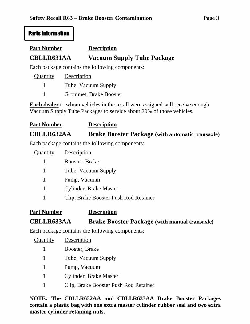
Part Number Description
CBLLR631AA Vacuum Supply Tube Package
Each package contains the following components:
Quantity Description
1 Tube, Vacuum Supply
1 Grommet, Brake Booster
Each dealer to whom vehicles in the recall were assigned will receive enough
Vacuum Supply Tube Packages to service about 20% of those vehicles.
Part Number Description
CBLLR632AA Brake Booster Package (with automatic transaxle)
Each package contains the following components:
Quantity Description
1 Booster, Brake
1 Tube, Vacuum Supply
1 Pump, Vacuum
1 Cylinder, Brake Master
1 Clip, Brake Booster Push Rod Retainer
Part Number Description
CBLLR633AA Brake Booster Package (with manual transaxle)
Each package contains the following components:
Quantity Description
1 Booster, Brake
1 Tube, Vacuum Supply
1 Pump, Vacuum
1 Cylinder, Brake Master
1 Clip, Brake Booster Push Rod Retainer
NOTE: The CBLLR632AA and CBLLR633AA Brake Booster Packages
contain a plastic bag with one extra master cylinder rubber seal and two extra
master cylinder retaining nuts.
Parts Information
Safety Recall R63 – Brake Booster Contamination Page 4
Part Number Description
05066440AA Lube, Zipper
NOTE: One bottle of Zipper Lube can repair 20 vehicles.
04318080AC Fluid, Brake (DOT 3) (MS.4574)
04318083 Gasket Maker
68324102AA Cup, Metal Bearing
NOTE: This part should only be ordered if the metal bearing
cup is lost during brake booster replacement.
No parts return required for this campaign.
The following special tools are required to perform this repair:
NPN wiTECH VCI Pod Kit
NPN Laptop Computer
NPN wiTECH Software
8358-1 Fitting, Master Cylinder Bleed
Parts Information (Continued)
Parts Return
Special Tools
Safety Recall R63 – Brake Booster Contamination Page 5
A. Inspect for Engine Oil in Brake Booster
1. With the engine off, pump the brake pedal several times to bleed off any
vacuum stored in the brake booster.
2. Disconnect and isolate the negative battery cable.
3. For vehicles with a 2.0L engine, partially remove the plastic engine cover.
4. For vehicles with a 2.0L engine, cover the throttle body opening with a shop
towel to prevent debris from entering the throttle body.
5. For vehicles with a 2.4L engine, remove and save the engine cover.
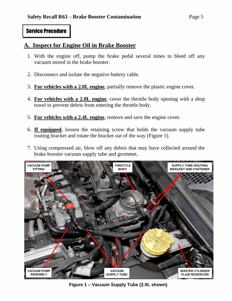
6. If equipped, loosen the retaining screw that holds the vacuum supply tube
routing bracket and rotate the bracket out of the way (Figure 1).
7. Using compressed air, blow off any debris that may have collected around the
brake booster vacuum supply tube and grommet.
Service Procedure
Figure 1 – Vacuum Supply Tube (2.0L shown)
SUPPLY TUBE ROUTING
BRACKET AND FASTENER
THROTTLE
BODY
VACUUM
SUPPLY TUBE
VACUUM PUMP ASSEMBLY
VACUUM PUMP
FITTING
MASTER CYLINDER
FLUID RESERVOIR
Safety Recall R63 – Brake Booster Contamination Page 6
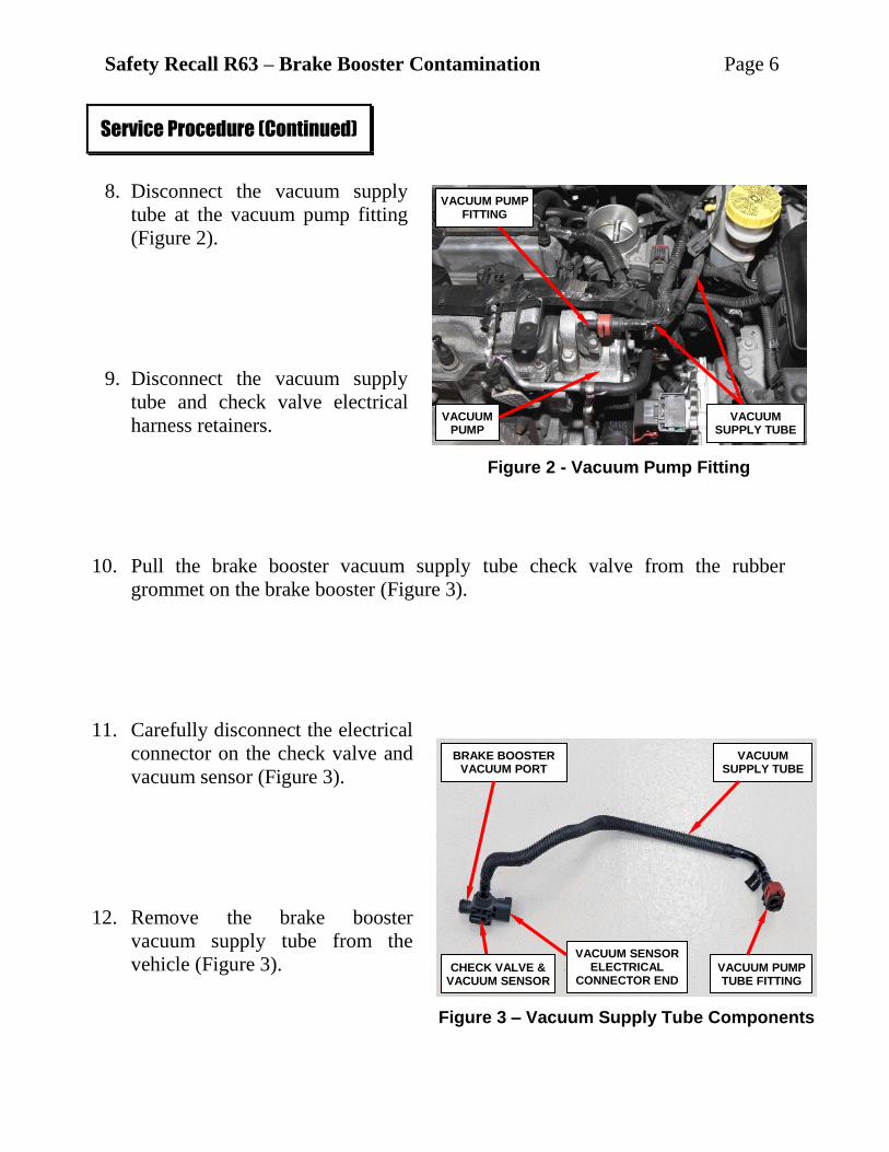
8. Disconnect the vacuum supply
tube at the vacuum pump fitting
(Figure 2).
9. Disconnect the vacuum supply
tube and check valve electrical
harness retainers.
10. Pull the brake booster vacuum supply tube check valve from the rubber
grommet on the brake booster (Figure 3).
11. Carefully disconnect the electrical
connector on the check valve and
vacuum sensor (Figure 3).
12. Remove the brake booster
vacuum supply tube from the
vehicle (Figure 3).
Service Procedure (Continued)
Figure 2 - Vacuum Pump Fitting
Figure 3 – Vacuum Supply Tube Components
VACUUM PUMP FITTING
VACUUM PUMP
VACUUM SUPPLY TUBE
BRAKE BOOSTER VACUUM PORT
CHECK VALVE & VACUUM SENSOR
VACUUM PUMP TUBE FITTING
VACUUM SUPPLY TUBE
VACUUM SENSOR ELECTRICAL
CONNECTOR END
Safety Recall R63 – Brake Booster Contamination Page 7
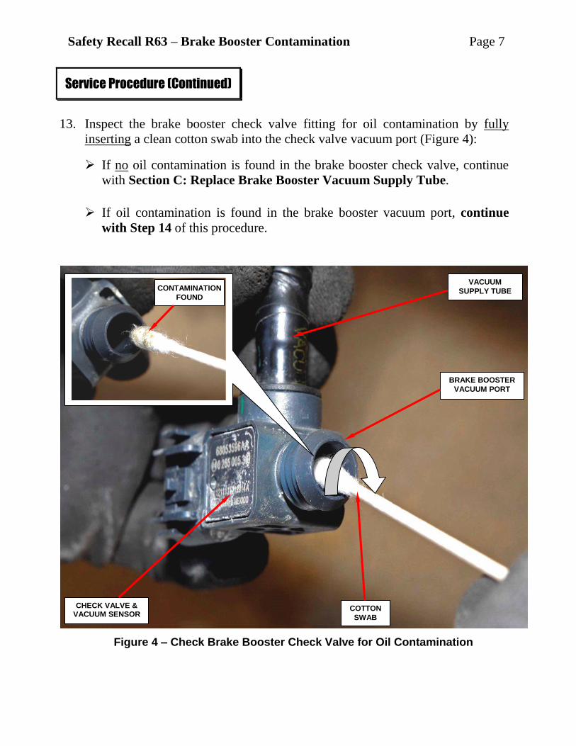
13. Inspect the brake booster check valve fitting for oil contamination by fully
inserting a clean cotton swab into the check valve vacuum port (Figure 4):
If no oil contamination is found in the brake booster check valve, continue
with Section C: Replace Brake Booster Vacuum Supply Tube.
If oil contamination is found in the brake booster vacuum port, continue
with Step 14 of this procedure.
Service Procedure (Continued)
Figure 4 – Check Brake Booster Check Valve for Oil Contamination
VACUUM
SUPPLY TUBE
BRAKE BOOSTER
VACUUM PORT
COTTON
SWAB
CHECK VALVE & VACUUM SENSOR
CONTAMINATION
FOUND
Safety Recall R63 – Brake Booster Contamination Page 8
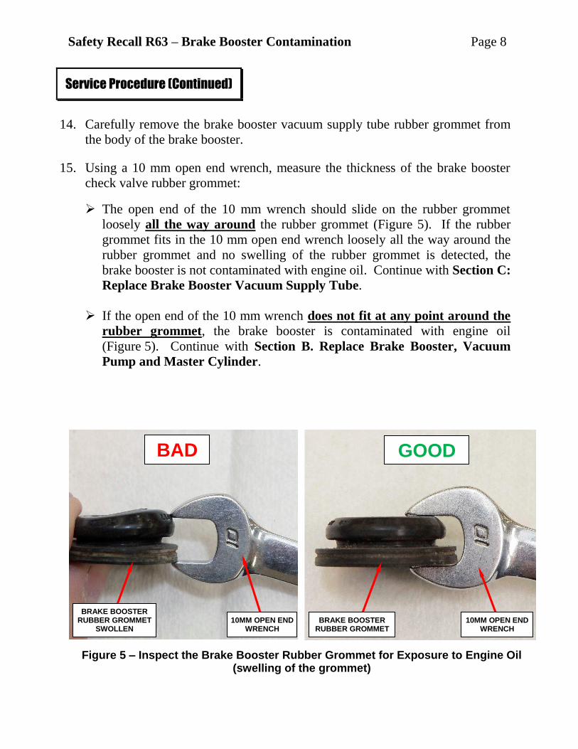
14. Carefully remove the brake booster vacuum supply tube rubber grommet from
the body of the brake booster.
15. Using a 10 mm open end wrench, measure the thickness of the brake booster
check valve rubber grommet:
The open end of the 10 mm wrench should slide on the rubber grommet
loosely all the way around the rubber grommet (Figure 5). If the rubber
grommet fits in the 10 mm open end wrench loosely all the way around the
rubber grommet and no swelling of the rubber grommet is detected, the
brake booster is not contaminated with engine oil. Continue with Section C:
Replace Brake Booster Vacuum Supply Tube.
If the open end of the 10 mm wrench does not fit at any point around the
rubber grommet, the brake booster is contaminated with engine oil
(Figure 5). Continue with Section B. Replace Brake Booster, Vacuum
Pump and Master Cylinder.
Service Procedure (Continued)
BAD GOOD
Figure 5 – Inspect the Brake Booster Rubber Grommet for Exposure to Engine Oil (swelling of the grommet)
BRAKE BOOSTER RUBBER GROMMET
SWOLLEN BRAKE BOOSTER
RUBBER GROMMET 10MM OPEN END
WRENCH 10MM OPEN END
WRENCH
Safety Recall R63 – Brake Booster Contamination Page 9
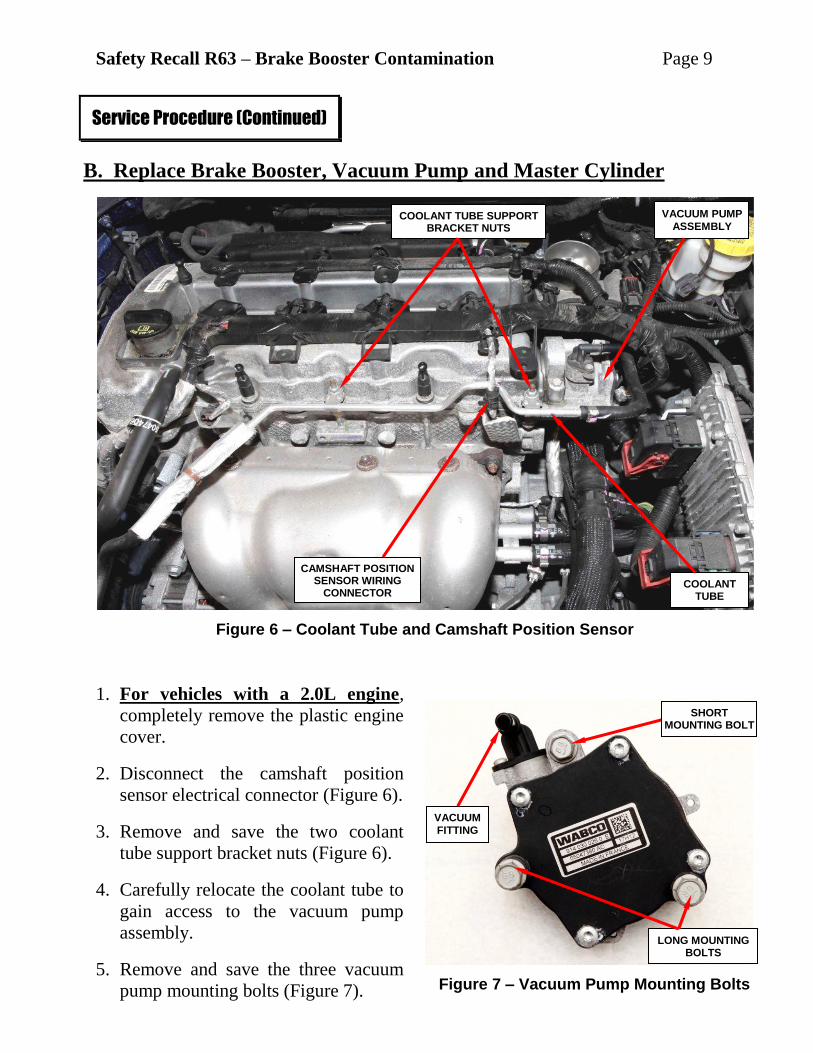
B. Replace Brake Booster, Vacuum Pump and Master Cylinder
1. For vehicles with a 2.0L engine,
completely remove the plastic engine
cover.
2. Disconnect the camshaft position
sensor electrical connector (Figure 6).
3. Remove and save the two coolant
tube support bracket nuts (Figure 6).
4. Carefully relocate the coolant tube to
gain access to the vacuum pump
assembly.
5. Remove and save the three vacuum
pump mounting bolts (Figure 7).
Service Procedure (Continued)
Figure 6 – Coolant Tube and Camshaft Position Sensor
Figure 7 – Vacuum Pump Mounting Bolts
COOLANT TUBE SUPPORT BRACKET NUTS
COOLANT TUBE
VACUUM PUMP
ASSEMBLY
LONG MOUNTING BOLTS
VACUUM
FITTING
CAMSHAFT POSITION SENSOR WIRING
CONNECTOR
SHORT MOUNTING BOLT
Safety Recall R63 – Brake Booster Contamination Page 10
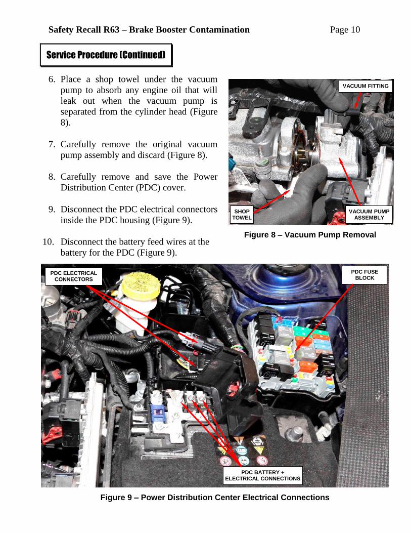
6. Place a shop towel under the vacuum
pump to absorb any engine oil that will
leak out when the vacuum pump is
separated from the cylinder head (Figure
8).
7. Carefully remove the original vacuum
pump assembly and discard (Figure 8).
8. Carefully remove and save the Power
Distribution Center (PDC) cover.
9. Disconnect the PDC electrical connectors
inside the PDC housing (Figure 9).
10. Disconnect the battery feed wires at the
battery for the PDC (Figure 9).
Service Procedure (Continued)
Figure 8 – Vacuum Pump Removal
Figure 9 – Power Distribution Center Electrical Connections
SHOP TOWEL
VACUUM PUMP ASSEMBLY
VACUUM FITTING
PDC ELECTRICAL CONNECTORS
PDC BATTERY + ELECTRICAL CONNECTIONS
PDC FUSE BLOCK
Safety Recall R63 – Brake Booster Contamination Page 11
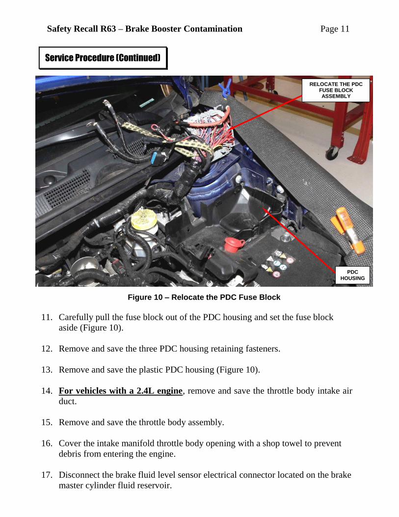
11. Carefully pull the fuse block out of the PDC housing and set the fuse block
aside (Figure 10).
12. Remove and save the three PDC housing retaining fasteners.
13. Remove and save the plastic PDC housing (Figure 10).
14. For vehicles with a 2.4L engine, remove and save the throttle body intake air
duct.
15. Remove and save the throttle body assembly.
16. Cover the intake manifold throttle body opening with a shop towel to prevent
debris from entering the engine.
17. Disconnect the brake fluid level sensor electrical connector located on the brake
master cylinder fluid reservoir.
Service Procedure (Continued)
Figure 10 – Relocate the PDC Fuse Block
PDC
HOUSING
RELOCATE THE PDC FUSE BLOCK ASSEMBLY
Safety Recall R63 – Brake Booster Contamination Page 12
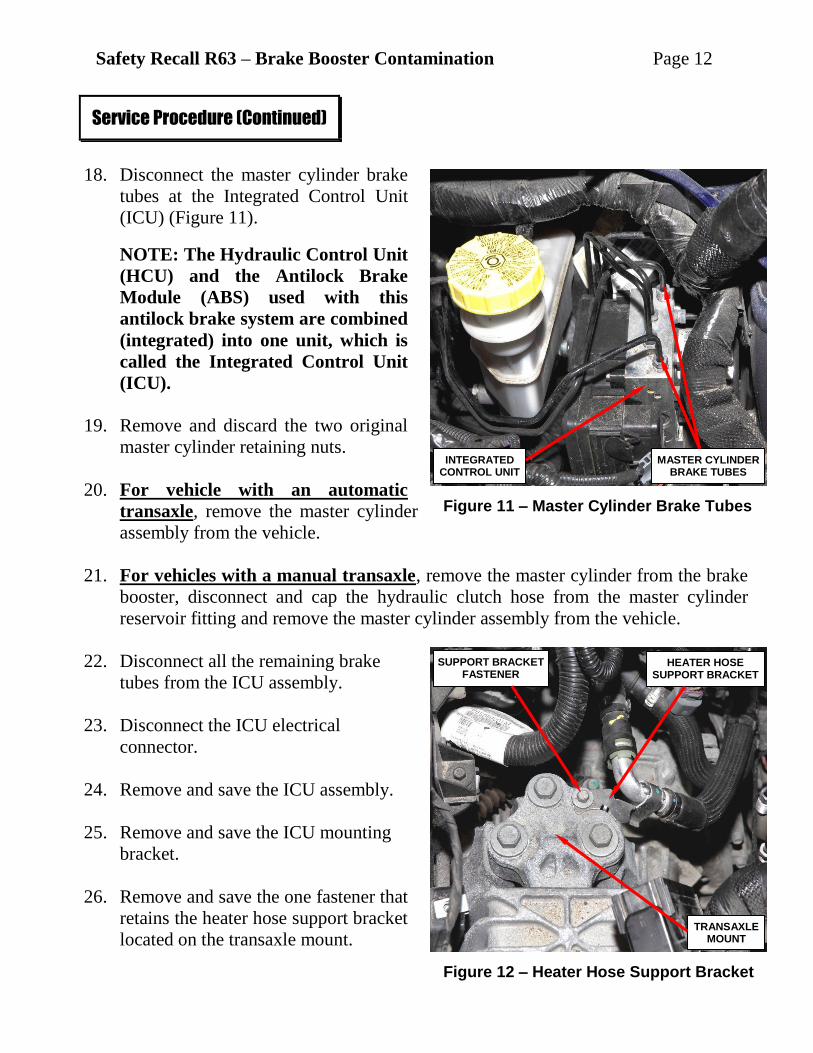
18. Disconnect the master cylinder brake
tubes at the Integrated Control Unit
(ICU) (Figure 11).
NOTE: The Hydraulic Control Unit
(HCU) and the Antilock Brake
Module (ABS) used with this
antilock brake system are combined
(integrated) into one unit, which is
called the Integrated Control Unit
(ICU).
19. Remove and discard the two original
master cylinder retaining nuts.
20. For vehicle with an automatic
transaxle, remove the master cylinder
assembly from the vehicle.
21. For vehicles with a manual transaxle, remove the master cylinder from the brake
booster, disconnect and cap the hydraulic clutch hose from the master cylinder
reservoir fitting and remove the master cylinder assembly from the vehicle.
22. Disconnect all the remaining brake
tubes from the ICU assembly.
23. Disconnect the ICU electrical
connector.
24. Remove and save the ICU assembly.
25. Remove and save the ICU mounting
bracket.
26. Remove and save the one fastener that
retains the heater hose support bracket
located on the transaxle mount.
Service Procedure (Continued)
Figure 11 – Master Cylinder Brake Tubes
Figure 12 – Heater Hose Support Bracket
MASTER CYLINDER BRAKE TUBES
TRANSAXLE MOUNT
HEATER HOSE SUPPORT BRACKET
SUPPORT BRACKET FASTENER
INTEGRATED CONTROL UNIT
Safety Recall R63 – Brake Booster Contamination Page 13
27. Remove and save the instrument panel end cap.
28. Remove and save the knee blocker assembly.
29. Remove and save the brake light switch located by the brake pedal.
CAUTION: Do not depress, lift or move the brake pedal during brake
lamp switch removal to avoid switch damage.
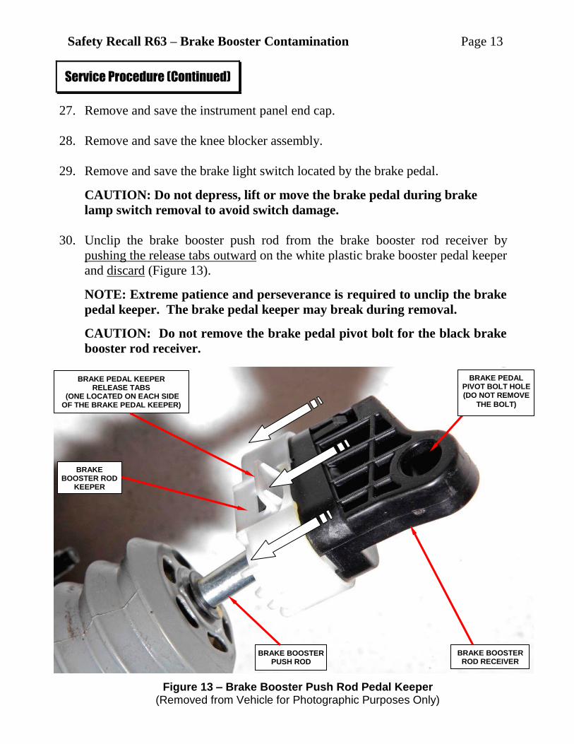
30. Unclip the brake booster push rod from the brake booster rod receiver by
pushing the release tabs outward on the white plastic brake booster pedal keeper
and discard (Figure 13).
NOTE: Extreme patience and perseverance is required to unclip the brake
pedal keeper. The brake pedal keeper may break during removal.
CAUTION: Do not remove the brake pedal pivot bolt for the black brake
booster rod receiver.
Service Procedure (Continued)
Figure 13 – Brake Booster Push Rod Pedal Keeper (Removed from Vehicle for Photographic Purposes Only)
BRAKE BOOSTER ROD RECEIVER
BRAKE BOOSTER ROD
KEEPER
BRAKE BOOSTER PUSH ROD
BRAKE PEDAL PIVOT BOLT HOLE (DO NOT REMOVE
THE BOLT)
BRAKE PEDAL KEEPER RELEASE TABS
(ONE LOCATED ON EACH SIDE OF THE BRAKE PEDAL KEEPER)
Safety Recall R63 – Brake Booster Contamination Page 14
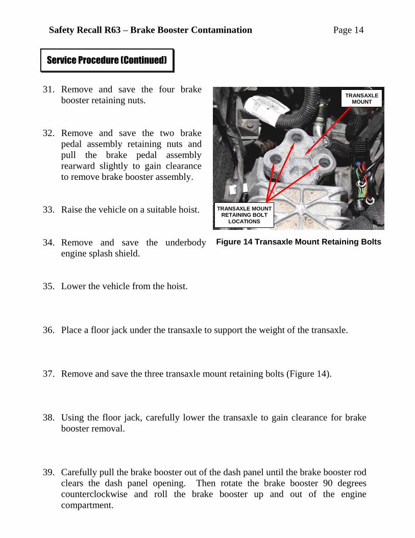
31. Remove and save the four brake
booster retaining nuts.
32. Remove and save the two brake
pedal assembly retaining nuts and
pull the brake pedal assembly
rearward slightly to gain clearance
to remove brake booster assembly.
33. Raise the vehicle on a suitable hoist.
34. Remove and save the underbody
engine splash shield.
35. Lower the vehicle from the hoist.
36. Place a floor jack under the transaxle to support the weight of the transaxle.
37. Remove and save the three transaxle mount retaining bolts (Figure 14).
38. Using the floor jack, carefully lower the transaxle to gain clearance for brake
booster removal.
39. Carefully pull the brake booster out of the dash panel until the brake booster rod
clears the dash panel opening. Then rotate the brake booster 90 degrees
counterclockwise and roll the brake booster up and out of the engine
compartment.
Service Procedure (Continued)
Figure 14 Transaxle Mount Retaining Bolts
TRANSAXLE MOUNT RETAINING BOLT
LOCATIONS
TRANSAXLE MOUNT
Safety Recall R63 – Brake Booster Contamination Page 15
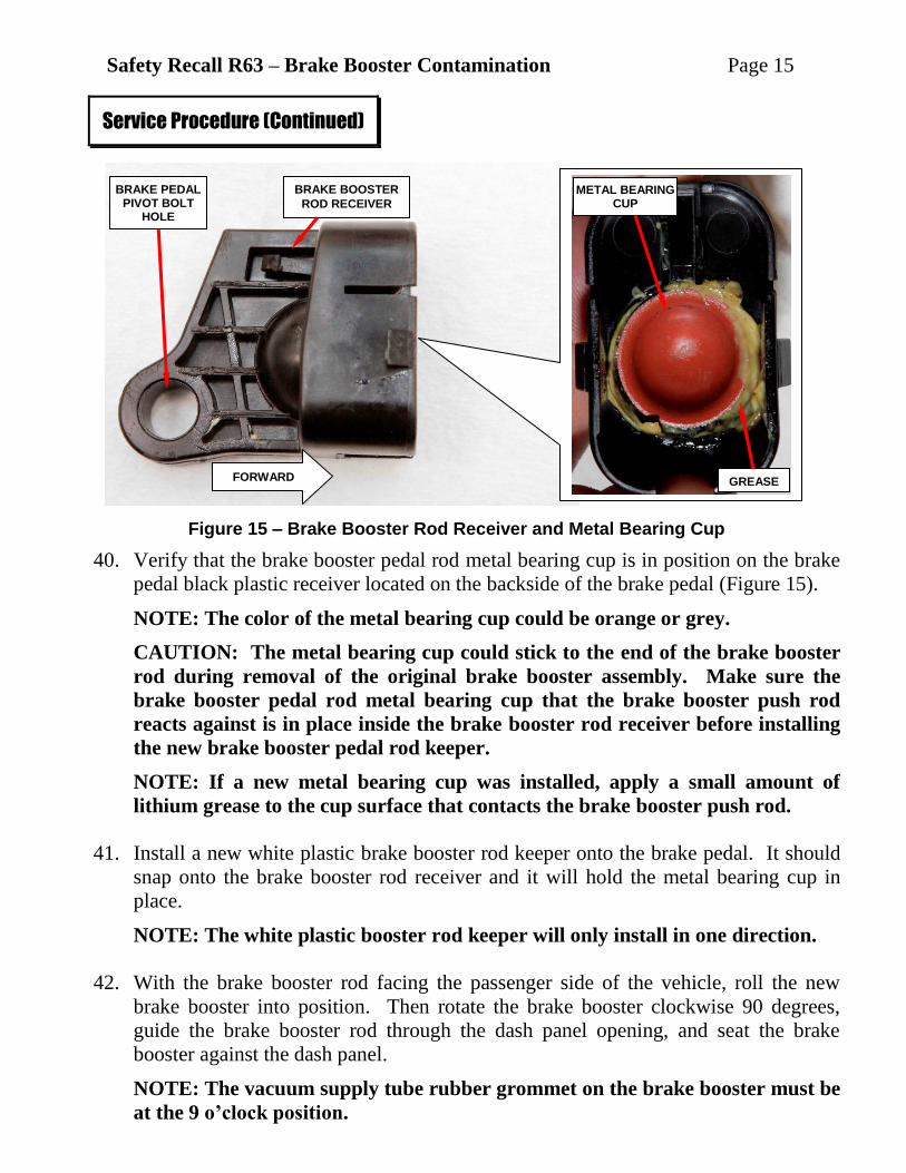
40. Verify that the brake booster pedal rod metal bearing cup is in position on the brake
pedal black plastic receiver located on the backside of the brake pedal (Figure 15).
NOTE: The color of the metal bearing cup could be orange or grey.
CAUTION: The metal bearing cup could stick to the end of the brake booster
rod during removal of the original brake booster assembly. Make sure the
brake booster pedal rod metal bearing cup that the brake booster push rod
reacts against is in place inside the brake booster rod receiver before installing
the new brake booster pedal rod keeper.
NOTE: If a new metal bearing cup was installed, apply a small amount of
lithium grease to the cup surface that contacts the brake booster push rod.
41. Install a new white plastic brake booster rod keeper onto the brake pedal. It should
snap onto the brake booster rod receiver and it will hold the metal bearing cup in
place.
NOTE: The white plastic booster rod keeper will only install in one direction.
42. With the brake booster rod facing the passenger side of the vehicle, roll the new
brake booster into position. Then rotate the brake booster clockwise 90 degrees,
guide the brake booster rod through the dash panel opening, and seat the brake
booster against the dash panel.
NOTE: The vacuum supply tube rubber grommet on the brake booster must be
at the 9 o’clock position.
Service Procedure (Continued)
Figure 15 – Brake Booster Rod Receiver and Metal Bearing Cup
BRAKE BOOSTER
ROD RECEIVER
METAL BEARING CUP
GREASE
BRAKE PEDAL PIVOT BOLT
HOLE
FORWARD
Safety Recall R63 – Brake Booster Contamination Page 16
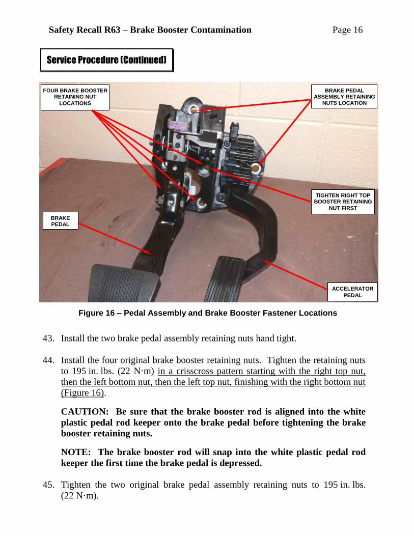
43. Install the two brake pedal assembly retaining nuts hand tight.
44. Install the four original brake booster retaining nuts. Tighten the retaining nuts
to 195 in. lbs. (22 N·m) in a crisscross pattern starting with the right top nut,
then the left bottom nut, then the left top nut, finishing with the right bottom nut
(Figure 16).
CAUTION: Be sure that the brake booster rod is aligned into the white
plastic pedal rod keeper onto the brake pedal before tightening the brake
booster retaining nuts.
NOTE: The brake booster rod will snap into the white plastic pedal rod
keeper the first time the brake pedal is depressed.
45. Tighten the two original brake pedal assembly retaining nuts to 195 in. lbs.
(22 N·m).
Service Procedure (Continued)
BRAKE PEDAL ASSEMBLY RETAINING
NUTS LOCATION
FOUR BRAKE BOOSTER RETAINING NUT
LOCATIONS
BRAKE PEDAL
ACCELERATOR
PEDAL
Figure 16 – Pedal Assembly and Brake Booster Fastener Locations
TIGHTEN RIGHT TOP BOOSTER RETAINING
NUT FIRST
Safety Recall R63 – Brake Booster Contamination Page 17
46. Press the brake pedal down to seat the brake booster push rod in the brake
booster rod receiver.
47. Using the floor jack, raise the transaxle into position and install the transaxle
mount retaining bolts. Tighten the three bolts to 77 ft. lbs. (104 N·m).
48. Lift the vehicle on the hoist.
49. Install the underbody engine splash shield.
50. Lower the vehicle from the hoist.
51. Use the following procedure to install the new vacuum pump:
NOTE: The vacuum pump must be installed at this point in the repair
procedure to allow dry time for the Mopar Gasket Maker Sealant.
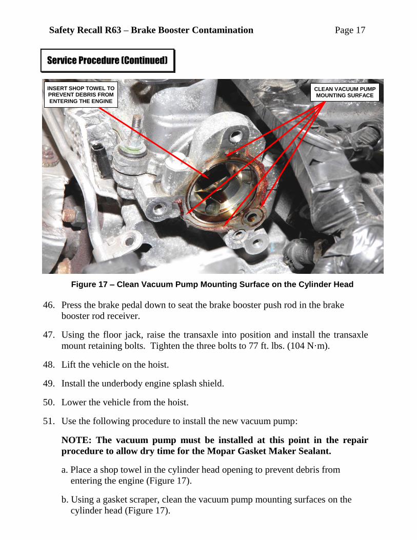
a. Place a shop towel in the cylinder head opening to prevent debris from
entering the engine (Figure 17).
b. Using a gasket scraper, clean the vacuum pump mounting surfaces on the
cylinder head (Figure 17).
Service Procedure (Continued)
Figure 17 – Clean Vacuum Pump Mounting Surface on the Cylinder Head
CLEAN VACUUM PUMP MOUNTING SURFACE
INSERT SHOP TOWEL TO PREVENT DEBRIS FROM
ENTERING THE ENGINE
Safety Recall R63 – Brake Booster Contamination Page 18
c. Spray brake clean onto a clean shop towel and carefully wipe down the
cylinder head where the vacuum pump mounts.
d. Spray brake clean onto a clean shop towel and carefully wipe down the
vacuum pump mounting surfaces.
e. Apply a thin coat of Mopar Gasket Maker sealant around both O-rings on the
new vacuum pump.
f. Install the new vacuum pump into position on the cylinder head.
g. Install the three vacuum pump retaining bolts. Tighten the retaining bolts
evenly to 180 in. lbs. (20 N·m).
NOTE: The short vacuum pump retaining bolt goes in the top location
(Figure 7).
52. Install the heater hose support bracket to the transaxle mount.
53. Install the ICU mounting bracket to the left frame rail. Tighten fasteners to
216 in. lbs. (25 N·m).
54. Install the ICU assembly to the ICU mounting bracket. Tighten fasteners to
71 in. lbs. (8 N·m).
55. Connect all of the brake tubes to the ICU assembly. Tighten the ICU tube nuts
to 160 in. lbs. (18 N·m).
56. Using special tool 8358-1, bench bleed the new master cylinder.
57. Install the master cylinder to the brake booster. Tighten the two new retaining
nuts finger tight.
NOTE: The Brake Booster Package contains a plastic bag with one extra
master cylinder rubber seal and two extra master cylinder retaining nuts.
58. For vehicles with a manual transaxle, connect the hydraulic clutch hose to the
reservoir fitting on the brake master cylinder.
59. Transfer the two brake tubes from the original master cylinder to the new
master cylinder. Tighten the tube nuts finger tight.
60. Connect the brake tubes from the master cylinder to the ICU ports.
Service Procedure (Continued)
Safety Recall R63 – Brake Booster Contamination Page 19
61. Tighten the new master cylinder-to-brake booster retaining nuts to 216 in. lbs.
(25 N·m).
NOTE: The Brake Booster Package contains a plastic bag with one extra
master cylinder rubber seal and two extra master cylinder retaining nuts.
62. Tighten the four tube nuts at both ends of the master cylinder brake tubes to
160 in. lbs. (18 N·m).
63. Connect the brake fluid level sensor electrical connector to the sensor on the
brake master cylinder fluid reservoir.
64. Install the brake light switch.
CAUTION: Do not depress, lift or move the brake pedal during brake
lamp switch installation to avoid improper switch adjustment.
65. Install the knee blocker assembly.
66. Install the instrument panel end cap.
67. Remove the protective shop towel from the intake manifold throttle body
opening.
68. Install the throttle body assembly. Tighten the mounting bolts to 71 in. lbs.
(8 N·m).
69. Install the plastic PDC housing.
70. Install the PDC fuse block.
71. Connect the electrical connectors located inside the PDC housing.
72. Connect the battery feed wires at the battery for the PDC.
73. Place the coolant tube into position and install the two retaining nuts.
74. Connect the camshaft position sensor electrical connector at the cylinder head.
75. Continue with Section C. Replace Brake Booster Vacuum Supply Tube.
Service Procedure (Continued)
Safety Recall R63 – Brake Booster Contamination Page 20
C. Replace Brake Booster Vacuum Supply Tube
1. For vehicles with the original brake booster and did not have the brake
booster grommet removed, carefully remove and discard the original brake
booster grommet and carefully install a new brake booster grommet.
2. Apply a light coat of Zipper Lube (or equivalent) to the outside of the check
valve fitting on the new brake vacuum tube.
CAUTION: DO NOT use any petroleum based lubricants on the check
valve fitting or grommet.
3. Place the new vacuum supply tube into position and connect the vacuum sensor
electrical connector to the sensor.
4. Insert the check valve fitting into the new brake booster grommet on the brake
booster body.
5. Route and clip the brake vacuum sensor harness retainers to the brake tube.
6. Route the vacuum supply tube into position and connect the tube to the vacuum
pump tube fitting.
7. If equipped, be sure the vacuum supply tube is snapped into place on the tube
routing bracket and tighten the bracket retaining screw to 71 in. lbs. (8 N·m).
8. For vehicles with a 2.4L engine, install the throttle body air inlet duct.
9. Install the engine cover.
10. Connect the negative battery cable to the negative battery post.
11. For vehicles that did not have the brake booster, vacuum pump, and
master cylinder replaced, continue with Section E. Electric Power Steering
Verification Test.
12. For vehicles that had the brake booster, vacuum pump, and master
cylinder replaced, continue with Section D. Bleed Brake Hydraulic System.
Service Procedure (Continued)
Safety Recall R63 – Brake Booster Contamination Page 21
D. Bleed Brake Hydraulic System
NOTE: There is no bleed procedure/program for the ICU in the wiTECH
scan tool.
CAUTION: Bleed the wheels in the following order: Left rear, right front,
right rear and then left front.
1. Attach a clear plastic hose to the bleeder screw and feed the hose into a clear jar
containing enough fresh brake fluid to submerge the end of the hose.
2. Have a helper pump the brake pedal three or four times and hold it in the down
position.
3. With the pedal in the down position, open the bleeder screw at least one full
turn.
4. Once the brake pedal has dropped, close the bleeder screw. After the bleeder
screw is closed, release the brake pedal.
5. Repeat the above steps until all trapped air is removed from that wheel circuit
(usually four or five times).
6. Bleed the remaining wheel circuits in the same manner until all air is removed
from the brake system. Monitor the fluid level in the master cylinder reservoir
to make sure it does not go dry.
CAUTION: Only DOT3 brake fluid must be used in the
hydraulic brake system.
7. Check and adjust brake fluid level to the “FULL” mark.
8. Check the brake pedal travel. If pedal travel is excessive or has not been
improved, some air may still be trapped in the system. Bleed the brakes again as
necessary.
9. Continue with Section E. Electric Power Steering Verification Test.
Service Procedure (Continued)
Safety Recall R63 – Brake Booster Contamination Page 22
E. Electric Power Steering Verification Test
1. Place the ignition in the “OFF” position.
2. Verify that all accessories are turned off, the battery is fully charged and the
charging system has a status of “Charged”.
3. Start a wiTECH session.
4. Turn the ignition to the “RUN” position.
5. Record all Diagnostic Trouble Codes (DTC’s).
6. Erase all DTC’s.
7. Start the engine.
8. Turn the steering wheel from stop to stop, holding at each stop position for one
second.
9. Place the ignition in the “OFF” position.
10. Wait five minutes.
11. After waiting five minutes, place the ignition in the “RUN” position.
12. Using the wiTECH scan tool, check for DTC’s.
13. Road test the vehicle for five minutes and verify that the brakes are operating
properly.
14. Verify that there are no DTC’s.
15. Return the vehicle to the customer.
Service Procedure (Continued)
Safety Recall R63 – Brake Booster Contamination Page 23
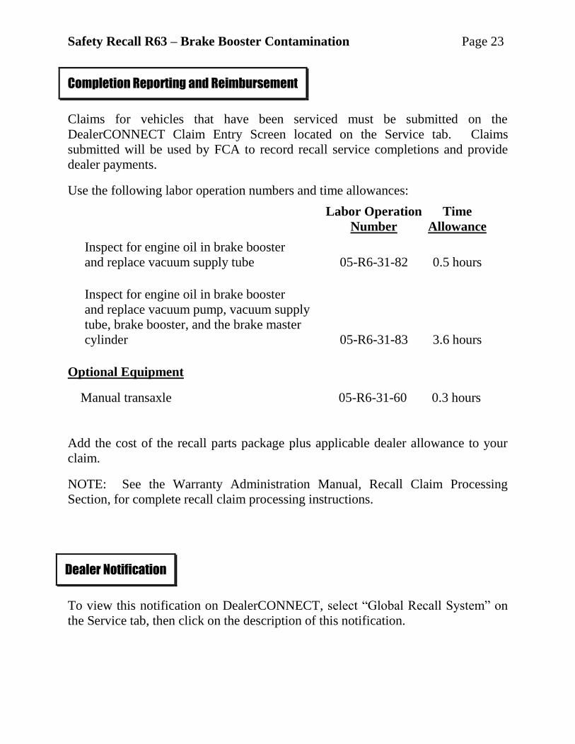
Claims for vehicles that have been serviced must be submitted on the
DealerCONNECT Claim Entry Screen located on the Service tab. Claims
submitted will be used by FCA to record recall service completions and provide
dealer payments.
Use the following labor operation numbers and time allowances:
Labor Operation Time
Number Allowance
Inspect for engine oil in brake booster
and replace vacuum supply tube 05-R6-31-82 0.5 hours
Inspect for engine oil in brake booster
and replace vacuum pump, vacuum supply
tube, brake booster, and the brake master
cylinder 05-R6-31-83 3.6 hours
Optional Equipment
Manual transaxle 05-R6-31-60 0.3 hours
Add the cost of the recall parts package plus applicable dealer allowance to your
claim.
NOTE: See the Warranty Administration Manual, Recall Claim Processing
Section, for complete recall claim processing instructions.
To view this notification on DealerCONNECT, select “Global Recall System” on
the Service tab, then click on the description of this notification.
Completion Reporting and Reimbursement
Dealer Notification
Safety Recall R63 – Brake Booster Contamination Page 24
All involved vehicle owners known to FCA are being notified of the service
requirement by first class mail. They are requested to schedule appointments for
this service with their dealers. A generic copy of the owner letter is attached.
Enclosed with each owner letter is an Owner Notification postcard to allow owners
to update our records if applicable.
All involved vehicles have been entered into the DealerCONNECT Global Recall
System (GRS) and Vehicle Information Plus (VIP) for dealer inquiry as needed. GRS provides involved dealers with an updated VIN list of their incomplete
vehicles. The owner’s name, address and phone number are listed if known.
Completed vehicles are removed from GRS within several days of repair claim
submission.
To use this system, click on the “Service” tab and then click on “Global Recall
System.” Your dealer’s VIN list for each recall displayed can be sorted by: those
vehicles that were unsold at recall launch, those with a phone number, city, zip
code, or VIN sequence.
Dealers must perform this repair on all unsold vehicles before retail delivery.
Dealers should also use the VIN list to follow up with all owners to schedule
appointments for this repair.
Recall VIN lists may contain confidential, restricted owner name and address information that
was obtained from the Department of Motor Vehicles of various states. Use of this information
is permitted for this recall only and is strictly prohibited from all other use.
If you have any questions or need assistance in completing this action, please
contact your Service and Parts District Manager.
Customer Services / Field Operations
FCA US LLC
Owner Notification and Service Scheduling
Vehicle Lists, Global Recall System, VIP and Dealer Follow Up
Additional Information
______________________________________________________________________________________
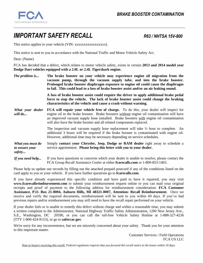
IMPORTANT SAFETY RECALL R63 / NHTSA 15V-800
This notice applies to your vehicle (VIN: xxxxxxxxxxxxxxxxx).
This notice is sent to you in accordance with the National Traffic and Motor Vehicle Safety Act.
Dear: (Name)
FCA has decided that a defect, which relates to motor vehicle safety, exists in certain 2013 and 2014 model year
Dodge Dart vehicles equipped with a 2.0L or 2.4L Tigershark engine.
The problem is... The brake booster on your vehicle may experience engine oil migration from the
vacuum pump, through the vacuum supply tube, and into the brake booster.
Prolonged brake booster diaphragm exposure to engine oil could cause the diaphragm
to fail. This could lead to a loss of brake booster assist and/or an air leaking sound.
A loss of brake booster assist could require the driver to apply additional brake pedal
force to stop the vehicle. The lack of brake booster assist could change the braking
characteristics of the vehicle and cause a crash without warning.
What your dealer
will do... FCA will repair your vehicle free of charge. To do this, your dealer will inspect for
engine oil in the brake booster. Brake boosters without engine oil contamination will have
an improved vacuum supply hose installed. Brake boosters with engine oil contamination
will also have the brake booster and all related components replaced.
The inspection and vacuum supply hose replacement will take ½ hour to complete. An
additional 3 hours will be required if the brake booster is contaminated with engine oil.
However, additional time may be necessary depending on service schedules.
What you must do
to ensure your
safety...
Simply contact your Chrysler, Jeep, Dodge or RAM dealer right away to schedule a
service appointment. Please bring this letter with you to your dealer.
If you need help... If you have questions or concerns which your dealer is unable to resolve, please contact the
FCA Group Recall Assistance Center at either fcarecalls.com or 1-800-853-1403.
Please help us update our records by filling out the attached prepaid postcard if any of the conditions listed on the
card apply to you or your vehicle. If you have further questions go to fcarecalls.com.
If you have already experienced this specific condition and have paid to have it repaired, you may visit
www.fcarecallreimbursement.com to submit your reimbursement request online or you can mail your original
receipts and proof of payment to the following address for reimbursement consideration: FCA Customer
Assistance, P.O. Box 21-8004, Auburn Hills, MI 48321-8007, Attention: Recall Reimbursement. Once we
receive and verify the required documents, reimbursement will be sent to you within 60 days. If you’ve had
previous repairs and/or reimbursement you may still need to have the recall repair performed on your vehicle.
If your dealer fails or is unable to remedy this defect without charge and within a reasonable time, you may submit
a written complaint to the Administrator, National Highway Traffic Safety Administration, 1200 New Jersey Ave.,
S.E., Washington, DC 20590, or you can call the toll-free Vehicle Safety Hotline at 1-888-327-4236
(TTY 1-800-424-9153), or go to safercar.gov.
We're sorry for any inconvenience, but we are sincerely concerned about your safety. Thank you for your attention
to this important matter.
Customer Services / Field Operations
FCA US LLC
Note to lessors receiving this recall: Federal regulation requires that you forward this recall notice to the lessee within 10 days.
BRAKE BOOSTER CONTAMINATION