Embed Size (px)
Citation preview
For Research Use Only. Not for use in diagnostic procedures.
Salt Converter-Cation Electrolytically Regenerated Suppressor 500
(Dionex SC-CERS 500)
031849 Revision 04 • December 2016
User M
anu
al
Thermo Scientific Product Manual for SC-CERS 500 Page 2 of 41 031849-04 For Research Use Only. Not for use in diagnostic procedures.
Product Manual
for
Salt Converter-Cation
Electrolytically Regenerated Suppressor 500
(Dionex SC-CERS 500)
Dionex SC-CERS 500 (4 mm) (Item # 083547)
Dionex SC-CERS 500 (2 mm) (Item # 083549)
Thermo Scientific Product Manual for SC-CERS 500 Page 3 of 41 031849-04 For Research Use Only. Not for use in diagnostic procedures.
© 2016 Thermo Fisher Scientific Inc. All rights reserved.
All trademarks are the property of Thermo Fisher Scientific Inc. and its subsidiaries.
Thermo Fisher Scientific Inc. provides this document to its customers with a product purchase to use in the product
operation. This document is copyright protected and any reproduction of the whole or any part of this document is
strictly prohibited, except with the written authorization of Thermo Fisher Scientific Inc.
The contents of this document are subject to change without notice. All technical information in this document is
for reference purposes only. System configurations and specifications in this document supersede all previous
information received by the purchaser.
Thermo Fisher Scientific Inc. makes no representations that this document is complete, accurate or error free and
assumes no responsibility and will not be liable for any errors, omissions, damage or loss that might result from
any use of this document, even if the information in the document is followed properly.
This document is not part of any sales contract between Thermo Fisher Scientific Inc. and a purchaser. This
document shall in no way govern or modify any Terms and Conditions of Sale, which Terms and Conditions of
Sale shall govern all conflicting information between the two documents.
For Research Use Only. Not for Use in Diagnostic Procedures.
Revision History:
Revision 04, December, 2016, Rebranded for Thermo Fisher Scientific Inc. Product name changed from SC-CSRS 300 to SC-CERS 500.
Thermo Scientific Product Manual for SC-CERS 500 Page 4 of 41 031849-04 For Research Use Only. Not for use in diagnostic procedures.
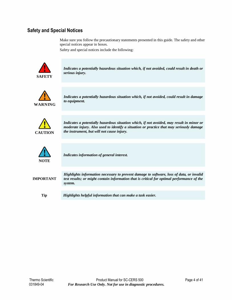
Safety and Special Notices
Make sure you follow the precautionary statements presented in this guide. The safety and other
special notices appear in boxes.
Safety and special notices include the following:
Indicates a potentially hazardous situation which, if not avoided, could result in death or
serious injury.
Indicates a potentially hazardous situation which, if not avoided, could result in damage
to equipment.
Indicates a potentially hazardous situation which, if not avoided, may result in minor or
moderate injury. Also used to identify a situation or practice that may seriously damage
the instrument, but will not cause injury.
Indicates information of general interest.
IMPORTANT
Highlights information necessary to prevent damage to software, loss of data, or invalid
test results; or might contain information that is critical for optimal performance of the
system.
Tip Highlights helpful information that can make a task easier.
SAFETY
!
WARNING
!
CAUTION
!
NOTE
!
Contents
Thermo Scientific Product Manual for SC-CERS 500 Page 5 of 41 031849-04 For Research Use Only. Not for use in diagnostic procedures.
Contents
1. Introduction to Electrolytically Regenerated Suppression for Cation Analysis ............................ 7
1.1 The Dionex Salt Converter-Cation Electrolytically Regenerated Suppressor 500
(Dionex SC-CERS 500) .............................................................................................................................. 8
1.1.1 Dionex SC-CERS 500 Operation ......................................................................................................... 9
1.2 Overview of Suppression Modes ............................................................................................................ 10
1.3 Mode of Operation Selection ................................................................................................................. 10
1.3.1 The AutoSuppression Recycle Mode ................................................................................................. 11
1.3.2 The AutoSuppression External Water Mode....................................................................................... 11
1.4 Shipment and Storage ............................................................................................................................ 12
1.4.1 Shipment ........................................................................................................................................... 12
1.4.2 Storage .............................................................................................................................................. 12
2. Installation...................................................................................................................................... 13
2.1 System Requirements ............................................................................................................................ 13
2.2 Electrolytically Regenerated Suppressor Control .................................................................................... 15
2.2.1 ERS Control for the CD20/ED40 CD25/ED50 (Dionex DX-600 instrument,
Dionex DX-500 instruments, Dionex DX-320)................................................................................... 15
2.2.2 SC20 Suppressor Controller .............................................................................................................. 17
2.2.3 Dionex RFC-10 or Dionex RFC-30 Controller ................................................................................... 18
2.3 Temperature .......................................................................................................................................... 19
2.4 Back Pressure Coils ............................................................................................................................... 19
2.5 Gas Separator Waste Tube for the Dionex SC-CERS 500 ....................................................................... 19
2.5.1 Assembly .......................................................................................................................................... 20
2.6 Electrolytically Regenerated Suppressor Current Selection ..................................................................... 20
2.6.1 Power Requirements.......................................................................................................................... 21
3. Operation ....................................................................................................................................... 22
3.1 Chemical Purity Requirements ............................................................................................................... 22
3.1.1 Inorganic Chemicals .......................................................................................................................... 22
3.1.2 Solvents ............................................................................................................................................ 22
3.1.3 Deionized Water ............................................................................................................................... 22
3.2 Installation and Start-Up ........................................................................................................................ 23
3.2.1 Dionex SC-CERS 500 Regeneration Instructions ............................................................................... 23
3.2.2 Dionex SC-CERS 500 Quick Start Instructions .................................................................................. 25
3.2.3 Installing the Dionex SC-CERS 500 .................................................................................................. 25
3.3 Plumbing for the Autosuppression Recycle Mode Operation .................................................................. 26
3.3.1 Eluent Flow Path Connections in the AutoSuppression Recycle Mode................................................ 27
3.3.2 AutoSuppression Recycle Mode Operation ........................................................................................ 27
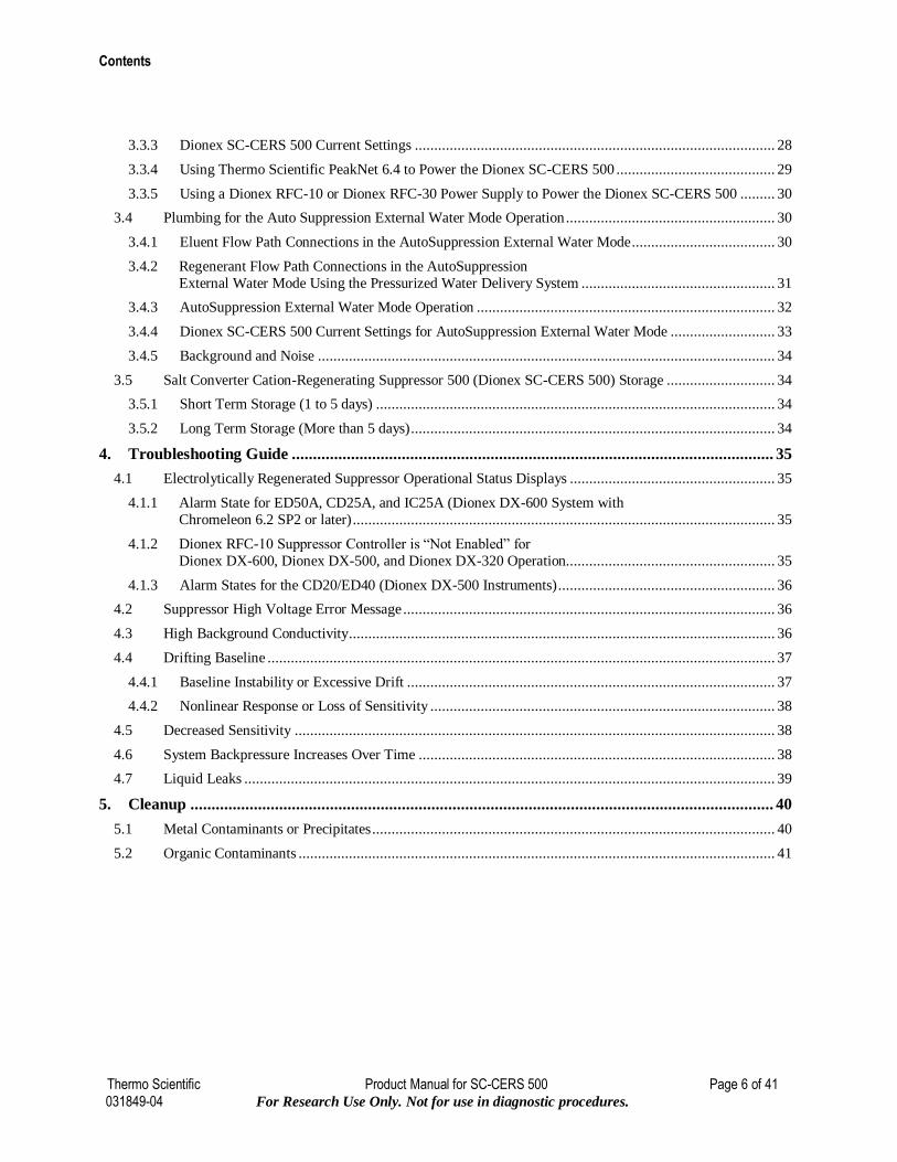
Contents
Thermo Scientific Product Manual for SC-CERS 500 Page 6 of 41 031849-04 For Research Use Only. Not for use in diagnostic procedures.
3.3.3 Dionex SC-CERS 500 Current Settings ............................................................................................. 28
3.3.4 Using Thermo Scientific PeakNet 6.4 to Power the Dionex SC-CERS 500 ......................................... 29
3.3.5 Using a Dionex RFC-10 or Dionex RFC-30 Power Supply to Power the Dionex SC-CERS 500 ......... 30
3.4 Plumbing for the Auto Suppression External Water Mode Operation ...................................................... 30
3.4.1 Eluent Flow Path Connections in the AutoSuppression External Water Mode ..................................... 30
3.4.2 Regenerant Flow Path Connections in the AutoSuppression
External Water Mode Using the Pressurized Water Delivery System .................................................. 31
3.4.3 AutoSuppression External Water Mode Operation ............................................................................. 32
3.4.4 Dionex SC-CERS 500 Current Settings for AutoSuppression External Water Mode ........................... 33
3.4.5 Background and Noise ...................................................................................................................... 34
3.5 Salt Converter Cation-Regenerating Suppressor 500 (Dionex SC-CERS 500) Storage ............................ 34
3.5.1 Short Term Storage (1 to 5 days) ....................................................................................................... 34
3.5.2 Long Term Storage (More than 5 days) .............................................................................................. 34
4. Troubleshooting Guide .................................................................................................................. 35
4.1 Electrolytically Regenerated Suppressor Operational Status Displays ..................................................... 35
4.1.1 Alarm State for ED50A, CD25A, and IC25A (Dionex DX-600 System with
Chromeleon 6.2 SP2 or later) ............................................................................................................. 35
4.1.2 Dionex RFC-10 Suppressor Controller is “Not Enabled” for
Dionex DX-600, Dionex DX-500, and Dionex DX-320 Operation...................................................... 35
4.1.3 Alarm States for the CD20/ED40 (Dionex DX-500 Instruments) ........................................................ 36
4.2 Suppressor High Voltage Error Message ................................................................................................ 36
4.3 High Background Conductivity .............................................................................................................. 36
4.4 Drifting Baseline ................................................................................................................................... 37
4.4.1 Baseline Instability or Excessive Drift ............................................................................................... 37
4.4.2 Nonlinear Response or Loss of Sensitivity ......................................................................................... 38
4.5 Decreased Sensitivity ............................................................................................................................ 38
4.6 System Backpressure Increases Over Time ............................................................................................ 38
4.7 Liquid Leaks ......................................................................................................................................... 39
5. Cleanup .......................................................................................................................................... 40
5.1 Metal Contaminants or Precipitates ........................................................................................................ 40
5.2 Organic Contaminants ........................................................................................................................... 41
1 – Introduction
Thermo Scientific Product Manual for SC-CERS 500 Page 7 of 41 031849-04 For Research Use Only. Not for use in diagnostic procedures.
1. Introduction to Electrolytically
Regenerated Suppression for Cation
Analysis
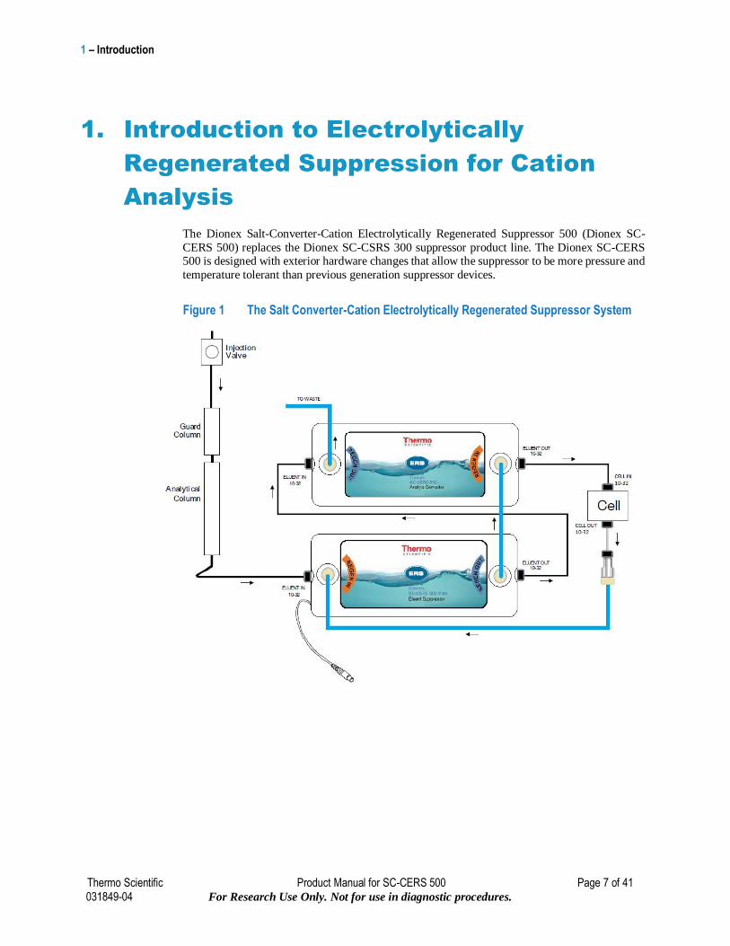
The Dionex Salt-Converter-Cation Electrolytically Regenerated Suppressor 500 (Dionex SC-
CERS 500) replaces the Dionex SC-CSRS 300 suppressor product line. The Dionex SC-CERS 500 is designed with exterior hardware changes that allow the suppressor to be more pressure and
temperature tolerant than previous generation suppressor devices.
Figure 1 The Salt Converter-Cation Electrolytically Regenerated Suppressor System
1 – Introduction
Thermo Scientific Product Manual for SC-CERS 500 Page 8 of 41 031849-04 For Research Use Only. Not for use in diagnostic procedures.
1.1 The Dionex Salt Converter-Cation Electrolytically Regenerated Suppressor 500 (Dionex SC-CERS 500)
The Dionex Salt Converter-Cation Electrolytically Regenerated Suppressor 500 (Dionex SC-
CERS® 500) is a post column electrolytic eluent suppressor for cation exchange applications
using conductivity detection. The Dionex SC-CERS 500 is used in cation exchange applications
as a replacement for the Dionex CERS 500 when extended linearity or increased sensitivity for
ammonium and amines are required. The Dionex SC-CERS 500 converts weakly ionized amines and ammonium to the highly ionized methanesulfonate acid, thus increasing their response and
extending the linear range to three orders of magnitude.
The Dionex SC-CERS 500 is a specialty suppressor package. The package consists of an Eluent
Suppressor component (ES) and an Analyte Converter component (AC), enabling the suppressed
conductivity detection of low-level ammonia and other amines with an extended linear response.
The Dionex SC-CERS 500 is installed in a cation ion exchange system and uses the same power supply used for SRS and ERS suppressors, as illustrated in Figure 1 “The Dionex Salt-Converter
Electrolytically Regenerated Suppression System.”
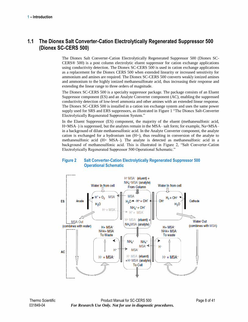
In the Eluent Suppressor (ES) component, the majority of the eluent (methanesulfonic acid,
H+MSA–) is suppressed, but the analytes remain in the MSA– salt form; for example, Na+MSA–
in a background of dilute methanesulfonic acid. In the Analyte Converter component, the analyte
cation is exchanged for a hydronium ion (H+), thus resulting in conversion of the analyte to methanesulfonic acid (H+ MSA–). The analyte is detected as methanesulfonic acid in a
background of methanesulfonic acid. This is illustrated in Figure 2, “Salt Converter-Cation
Electrolytically Regenerated Suppressor 500 Operational Schematic.”
Figure 2 Salt Converter-Cation Electrolytically Regenerated Suppressor 500 Operational Schematic
1 – Introduction
Thermo Scientific Product Manual for SC-CERS 500 Page 9 of 41 031849-04 For Research Use Only. Not for use in diagnostic procedures.
Always remember that assistance is available for any problem that may be encountered
during the shipment or operation of Thermo Scientific DIONEX instrumentation and
columns through the Thermo Scientific North America Technical Call Center at 1-800-
DIONEX-0 (1-800-346-6390) or through any of the Thermo Scientific Offices listed in,
“Thermo Scientific Worldwide Offices.”
For example, ammonium hydroxide (ammonia) which is weakly dissociated is converted to ammonium MSA in the ES component, and in the AC component the ammonium MSA is
converted to the conductive MSA form. Since MSA is fully dissociated, linear response vs.
concentration calibration is observed at a wide range of concentration.
The Dionex SC-CERS 500 suppressor is recommended and optimized for isocratic MSA
(methanesulfonic acid) only. The Dionex SC-CERS 500 is compatible with typical HPLC
solvents up to 40%. The external water mode must be used for eluents containing solvents.
The Dionex SC-CERS 500 is available in both 4 mm and 2 mm formats. The Dionex SC-CERS
500 (2 mm) is specially designed with reduced internal volume to ensure optimum performance
with 2 mm and 3 mm i. d. columns and microbore systems.
The electrolytic suppressor component of the Dionex SC-CERS 500 includes two regenerant
compartments and one eluent compartment separated by ion exchange membranes. Regenerant
flow channels and an eluent flow channel are defined by the membranes. The eluent flow is in a
direction that is concurrent to the regenerant flow in the Eluent Suppressor component and
countercurrent in the Analyte Converter.
In the Eluent Suppressor, electrodes are placed along the regenerant channels. When an electrical
potential is applied across the electrodes, water from the regenerant channels is electrolyzed,
supplying regenerant hydroxide ions (OH-) for the neutralization reaction. The membrane allows
these hydroxide ions to pass into the eluent chamber resulting in the conversion of the electrolyte
of the eluent to a weakly ionized form. Eluent anions are simultaneously passed into the
regenerant chamber to maintain charge balance. In the Eluent Suppressor the electrode lengths
are optimized to promote a transfer of methane sulfonic acid across the membranes at the outlet
end. This transfer forms dilute MSA in the eluent stream resulting in a slightly elevated
background and the analyte is in the MSA form.
The Analyte Converter is a chemical suppression system and has no electrodes. This component exchanges the analyte for hydronium ions, forming methanesulfonic acid.
1.1.1 Dionex SC-CERS 500 Operation
In operation as shown in Figure 1, the regenerant flow is in the same direction as the eluent flow
in the ES Component. This ensures that the screens and the membranes are in the MSA form and
converts the analyte to the MSA form as shown in Figure 2. The electrodes in the ES are optimized
to ensure that there is a small transfer of MSA to aid the dissociation of all species. The effluent
(MSA) from the ES is diverted into the regenerant channel of the AC in order to regenerate the
AC chemically as shown in Figure 2. All cations are converted to MSA as shown in Figure 2,
“Salt Converter-Cation Electrolytically Regenerated Suppressor 500 Operational Schematic.”
NOTE
!
1 – Introduction
Thermo Scientific Product Manual for SC-CERS 500 Page 10 of 41 031849-04 For Research Use Only. Not for use in diagnostic procedures.
1.2 Overview of Suppression Modes
There are two basic modes of suppression performed with the Dionex Salt-Converter Cation
Electrolytically Regenerated Suppressor 500 (Dionex SC-CERS 500):
AutoSuppression Recycle Mode
AutoSuppression External Water Mode
The following sections explain how each mode works and recommend which mode to use for an application. Once the mode of operation is determined, more detailed plumbing configuration and
operating instructions can be found in Section 3, “Dionex Salt- Converter-Cation Electrolytically
Regenerated Suppressor 500 Operation.”
1.3 Mode of Operation Selection
The Dionex SC-CERS 500 mode of operation depends mainly on the eluent composition. Eluents
containing organic solvents are not compatible with the AutoSuppression Recycle Mode. The
AutoSuppression External Water Mode should be used instead.
The Eluent Suppressor component of the Dionex SC-CERS 500 uses dilute MSA and electrolysis
as the regenerant to achieve substantial eluent suppression. The most common mode of operation
is the AutoSuppression Recycle Mode. In this mode of operation, substantially suppressed eluent flows from the eluent outlet of the suppressor into the conductivity cell and is then recycled
through the Dionex SC-CERS 500 regenerant chambers. This eliminates the need for an external
source of water but restricts the regenerant flow rate to the eluent flow rate. The Analyte Converter
component uses the MSA effluent from the Eluent Suppressor as a regenerant to achieve
conversion of the analytes to MSA. The AutoSuppression External Water Mode incorporates
an external source of deionized water flowing through the regenerant chambers. This requires the
installation of a water delivery system such as a pressurized bottle system or peristaltic pump to
provide an external source of water. With this configuration the regenerant flow rate is not
restricted to the eluent flow rate.
Both the AutoSuppression Recycle Mode and the AutoSuppression External Water Mode require application of electric current to the Eluent Suppressor component of the Dionex SC-
CERS 500. To improve performance and increase suppressor lifetime, the optimum current must
be applied. The optimum current setting produces just enough hydroxide ions to displace the
eluent counter ions, thus neutralizing the eluent. When using solvents in the eluent, the optimum
current setting is critical for prevention of oxidation of the solvent. See Section 3.3.3, “Dionex
SC-CERS 500 Current Settings,” on setting the optimum current.
1 – Introduction
Thermo Scientific Product Manual for SC-CERS 500 Page 11 of 41 031849-04 For Research Use Only. Not for use in diagnostic procedures.
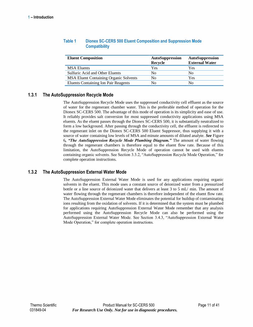
Table 1 Dionex SC-CERS 500 Eluent Composition and Suppression Mode Compatibility
Eluent Composition AutoSuppression
Recycle
AutoSuppression
External Water
MSA Eluents Yes Yes
Sulfuric Acid and Other Eluents No No
MSA Eluent Containing Organic Solvents No Yes
Eluents Containing Ion Pair Reagents No No
1.3.1 The AutoSuppression Recycle Mode
The AutoSuppression Recycle Mode uses the suppressed conductivity cell effluent as the source
of water for the regenerant chamber water. This is the preferable method of operation for the
Dionex SC-CERS 500. The advantage of this mode of operation is its simplicity and ease of use.
It reliably provides salt conversion for most suppressed conductivity applications using MSA
eluents. As the eluent passes through the Dionex SC-CERS 500, it is substantially neutralized to form a low background. After passing through the conductivity cell, the effluent is redirected to
the regenerant inlet on the Dionex SC-CERS 500 Eluent Suppressor, thus supplying it with a
source of water containing low levels of MSA and minute amounts of diluted analyte. See Figure
6, “The AutoSuppression Recycle Mode Plumbing Diagram.” The amount of water flowing
through the regenerant chambers is therefore equal to the eluent flow rate. Because of this
limitation, the AutoSuppression Recycle Mode of operation cannot be used with eluents
containing organic solvents. See Section 3.3.2, “AutoSuppression Recycle Mode Operation,” for
complete operation instructions.
1.3.2 The AutoSuppression External Water Mode
The AutoSuppression External Water Mode is used for any applications requiring organic
solvents in the eluent. This mode uses a constant source of deionized water from a pressurized
bottle or a line source of deionized water that delivers at least 3 to 5 mL/ min. The amount of
water flowing through the regenerant chambers is therefore independent of the eluent flow rate.
The AutoSuppression External Water Mode eliminates the potential for buildup of contaminating
ions resulting from the oxidation of solvents. If it is determined that the system must be plumbed
for applications requiring AutoSuppression External Water Mode remember that any analysis performed using the AutoSuppression Recycle Mode can also be performed using the
AutoSuppression External Water Mode. See Section 3.4.3, “AutoSuppression External Water
Mode Operation,” for complete operation instructions.
1 – Introduction
Thermo Scientific Product Manual for SC-CERS 500 Page 12 of 41 031849-04 For Research Use Only. Not for use in diagnostic procedures.
1.4 Shipment and Storage
1.4.1 Shipment
The Dionex Salt Converter-Cation Electrolytically Regenerated Suppressor 500 (Dionex
SC-CERS 500) contains components that are heat sensitive. The suppressor should not be
subjected to temperatures above 40°C during shipment, storage, or operation.
1.4.2 Storage
Ensure the suppressor is stored in a temperature controlled environment away from direct
exposure to sunlight or other sources of heat. Do not store the suppressor in a non-
temperature controlled environment where temperatures in excess of 40°C are commonly
experienced, such as a parked car, a tool shed, or a lab-bench in close proximity to an open
window with direct sunlight.
CAUTION
!
CAUTION
!
2 – Installation
Thermo Scientific Product Manual for SC-CERS 500 Page 13 of 41 031849-04 For Research Use Only. Not for use in diagnostic procedures.
2. Installation
2.1 System Requirements
The Dionex SC-CERS 500 is designed to be run on any Dionex Ion Chromatograph (IC) equipped with a cation exchange column set and suppressed conductivity detection. Dionex ICS-5000+,
Dionex ICS-5000, Dionex ICS-3000, Dionex ICS-2500, Dionex ICS-2100, Dionex ICS-2000,
Dionex ICS-1600, Dionex ICS-1500, Dionex ICS-1100, Dionex 1000, Dionex DX-600 (with
CD25A or ED50A) and Dionex DX-320 (with IC25A) module contain an SRS or ERS control
integrated into the detector. Dionex DX-600 systems with CD25 or ED50 detector, Dionex DX-
500 systems, Dionex DX-320 systems with IC20 or IC25 module, Dionex DX-500 systems with
CDM-3 or PED-2 systems contain an SRS or ERS control that lacks 1 mA incremental control, it
is recommended to use a Dionex RFC-10 or Dionex RFC-30 to achieve 1 mA incremental control.
Older systems require the purchase of the Dionex RFC-10 or Dionex RFC-30 Suppressor
Controller for first time installation of the Dionex SC-CERS 500. See Table 2, “Electrolytically
Regenerated Suppressor Requirements for Selected Ion Chromatographs.”
Table 2 Electrolytically Regenerated Suppressor Requirements for Selected Ion Chromatographs
Dionex Ion Chromatograph Series Module
Dionex RFC-10 or Dionex RFC-30 Suppressor Controller Required?
2000i YES
QIC YES
2000 SP YES
4000i YES
4500i YES
8000 YES
8100 CDM-2, PED CDM-3, PED-2
YES RECOMMENDED
(for 1 mA increment control)
8200 CDM-3, PED-2 RECOMMENDED (for 1 mA increment control)
Dionex DX-320 IC20 IC25 IC25A
RECOMMENDED RECOMMENDED
NO
(for 1 mA increment control) (for 1 mA increment control) (integral with detector)
Dionex DX-300 CDM-2, PED CDM-3, PED-2
YES RECOMMENDED
(for 1 mA increment control)
Dionex DX-500 RECOMMENDED (for 1 mA increment control)
Dionex DX-600 CD25 CD25A ED50 ED50A
RECOMMENDED NO
RECOMMENDED NO
(for 1 mA increment control) (integral with detector) (for 1 mA increment control) (integral with detector)
Dionex DX-800 RECOMMENDED (for 1 mA increment control)
Dionex ICS-1000/1500/2000 /1100/1600/2100
NO (integral with system)
Dionex ICS-2500 NO (integral with detector)
Dionex ICS-3000 /5000/5000+
NO (integral with detector)
2 – Installation
Thermo Scientific Product Manual for SC-CERS 500 Page 14 of 41 031849-04 For Research Use Only. Not for use in diagnostic procedures.
The Dionex SC-CERS 500 is installed in the column compartment of the chromatography module
immediately after the analytical column and before the conductivity detector cell. On the Dionex
ICS-5000+/5000/3000, the Dionex SC-CERS 500 ES mounts on the CD in the DC module; the
Dionex SC-CERS 500 AS mounts on the suppressor plate of the second detector console (if
fitted), or in the top section of the upper compartment. On the Dionex ICS-
2100/2000/1600/1500/1100/1000, the Dionex SC-CERS 500 ES mounts on the vertical
suppressor brackets between the CD cell and column in the component panel; the Dionex SC-CERS 500 AS mounts on the horizontal suppressor brackets at the top of the component panel.
On the Dionex Integrion the Dionex SC-CERS 500 ES mounts on the tangs in the detector
compartment; the Dionex SC-CERS 500 AS need to be affixed next to the ES in the detector
compartment using double sided tape or Velcro. The following components are required for the
installation of the Dionex SC-CERS 500 in a Dionex” Ion Chromatograph:
Table 3 Gas Separator Waste Tube
P/N Description
Found in: 046297 046298 045935 050130 059218 045720
ED40, ED50/A Shipkit CD20, CD25/A Shipkit CDM-3 On-Line Shipkit Dionex DX-120 Shipkit Dionex DX-320 Shipkit RFC-30 Shipkit
Additional components are required to plumb a 2-mm system:
052324 Microbore tubing (containing tubing, fittings and 2-mm backpressure coils required for plumbing a 2-mm system). NOTE: Backpressure coils must not be used Dionex SC-CERS 500.
SC-CSRS 300 Spare Parts: 016388 024305
Syringe, 1.0 mL, disposable For flushing the Dionex SC-CERS 500 at start-up. Syringe Adapter, female Luer lock, 1/4-28 threads
Installation Kit for LC30: 060044 Metal bracket, spacers and screws required for mounting the SC-CSRS 300 AC in a LC30.
Options: Pressurized Water Delivery System (used with the AutoSuppression External Water Mode)
038018 External Regenerant Installation Kit For Dionex SC-CERS 500 suppressor operation in the External Water mode when up to 40% HPLC solvents are used in the eluent. Contains one pressure regulator (0-30 psi/0-210 kPa), and all tubing and fittings required to install the Dionex SC-CERS 500.
RFC-10 / RFC-30 See the Reagent-Free Controller Manual for detailed instructions.
2 – Installation
Thermo Scientific Product Manual for SC-CERS 500 Page 15 of 41 031849-04 For Research Use Only. Not for use in diagnostic procedures.
THE DIONEX SC-CERS 500 MUST BE OPERATED WITH THE GAS SEPARATOR
WASTE TUBE (P/N 045460)
During the course of installing and using the Dionex SC-CERS 500, it may be necessary to
assemble 1/4-28 or 10-32 ferrule/ bolt style liquid lines. See, “Installation of DIONEX
Liquid Line Fittings,” Document No. 031432, for complete details.
2.2 Electrolytically Regenerated Suppressor Control
In this section, choose the detector you are using and read the discussion on Dionex SC-CERS
500 current control. See Section 3.3.3, “Dionex SC-CERS 500 Current Settings,” for choosing
the correct current settings.
Electrolytically Regenerated Suppressor Control consists of the electronic components necessary to control and provide conditioned power to the Dionex SC-CERS 500 Suppressors.
Always turn the pump and ERS Control on and off at the same time! Eluent flow through
the Dionex SC-CERS 500 is required for proper operation. However, without current, the
membranes and screens in the Dionex SC-CERS 500 will become expended by the flowing
eluent resulting in anomalous analyte peak areas and baseline drift. If this should occur,
perform the procedure outlined in Section 4.4.2, Nonlinear Response or Loss of Sensitivity.
The Dionex SC-CERS 500 can also be controlled using the Dionex RFC-10 Power Supply Module which has the capabilities of supplying the optimum current to the Dionex SC-CERS 500.
See Section 3.3.5, “Using a Dionex RFC-10 / Dionex RFC-30 Suppressor Controller to Power the
Dionex SC-CERS 500,” for information on using the Dionex RFC-10 to control the Dionex SC-
CERS 500.
2.2.1 ERS Control for the CD20/ED40 CD25/ED50 (Dionex DX-600 instrument, Dionex DX-500 instruments, Dionex DX-320)
SRS/ERS control for these instruments is accessible from the detector front panel or
PeakNet/Chromeleon software. For information on operation from PeakNet/Chromeleon, please
see the Help file in the Run or Method files.
If using the ED40, first select “Conductivity Mode” from the “Main Screen”
If using the Dionex DX-600, DX-500, or Dionex DX-320, it is recommended to use a Dionex
RFC-10 or Dionex RFC-30 power supply to provide more accurate current to the Dionex
SC-CERS 500.
To operate the SRS/ERS from the front panel of these detectors:
A. Make sure the detector is in one of the main conductivity screens by choosing “Main
Screen” or “Detail Screen.”
CAUTION
!
NOTE
!
CAUTION
!
NOTE
!
NOTE
!
2 – Installation
Thermo Scientific Product Manual for SC-CERS 500 Page 16 of 41 031849-04 For Research Use Only. Not for use in diagnostic procedures.
B. Press the MENU button until you see this as an option. Press the appropriate number
followed by “Enter.”
C. Make sure you are in 1, the “Local” mode. If you are in the “Remote” mode use the
arrow keys to select “Local” and press “Enter.”
D. In the “Main” or “Detail” screens, navigate, using the arrow keys, to the field labeled
“SRS.” Set the current output level. Increase or decrease the levels by using the select
keys. These are labeled 50, 100, 300, and 500 mA. Remember to hit “Enter” after choosing a setting.
SRS/ERS Control Connections for the CD20/ED40 (Dionex DX-500 instruments)
SRS/ERS Control Connections for the CD20/ED40 (Dionex DX-600 instruments, Dionex DX-320)
For these instruments, connect one end of the SRS/ERS control cable to slot 2, plug J3 behind the
instrument front panel. Route the cable through the chase beneath the electronics to the back.
Route the female ERS plug end to the chromatography module that you are using. Place the cable
close to the ERS and attach.
SRS/ERS Line Voltage for the CD20/ED40 (Dionex DX-500 instruments)
SRS/ERS Line Voltage for the CD20/ED40 (Dionex DX-600 instruments, Dionex DX-320) These detectors have automatic switching power supplies to adjust to the line voltage. No user
settings are required.
SRS/ERS Power Control for the CD20/ED40 (Dionex DX-500 instruments)
SRS/ERS Power Control for the CD20/ED40 (Dionex DX-600 instruments, Dionex DX-320)
The CD20 and ED40 are controlled from the instrument front panel on Dionex DX-500
instruments. Navigate to the SRS field and use the “Select” keys to scroll the current settings to
“Off” Press “Enter.”
As a general operating precaution, never apply current to the Dionex SC-CERS 500 without
eluent or water regenerant flowing through the Dionex SC-CERS 500 at the same time.
Always apply current whenever eluent is running through the suppressor.
SRS/ERS Control for the Dionex DX-120
The Dionex SC-CERS 500 is not compatible with the Dionex DX-120 power supply. A Dionex
RFC-10 or RFC-30 power supply is recommended for use with Dionex DX-120 instruments.
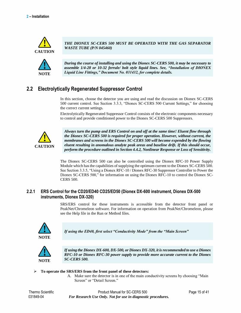
SRS/ERS Control for the CDM-3/PED-2 (Dionex DX-300 Instruments)
Figure 3 CDM-3/PED-2 Control
CAUTION
!
2 – Installation
Thermo Scientific Product Manual for SC-CERS 500 Page 17 of 41 031849-04 For Research Use Only. Not for use in diagnostic procedures.
SRS/ERS Control on the CDM-3 or PED-2 receives power when the Detector Power Switch, located on
the rear panel of the CDM-3 or the PED-2 is turned On.
The Cell OFF/ON button, on the CDM-3 or the PED-2 front panel, turns current flow On or Off to both the
cell and the Dionex SC-CERS 500.
SRS Control Current Selector switch on the CDM-3 and PED-2 is located on the top panel of the detector.
SRS/ERS Control Connections for the CDM-3/PED-2 (Dionex DX-300 Instruments) For CDM-3 and PED-2 SRS/ERS Control, use the SRS/ERS Control extension cable (P/N 045343) to
connect the SRS/ERS Control output connector on the back of the detector chassis, to the Dionex SC-CERS
500 current input connector.
SRS/ERS Line Voltage for the CDM-3/PED-2 (Dionex DX-300 Instruments) The SRS/ERS control portion of the detector receives its power directly from the CDM-3 or PED-2
detector. If the detector's voltage control (CORCOM) is properly set (see the appropriate CDM-3 or PED-2
Operator's Manual), the control portion of the detector will receive the correct power without further
adjustment.
SRS/ERS Power Control for The CDM-3/PED-2 (Dionex DX-300 Instruments)
The control and display panels on the CDM-3 and PED-2 detectors for the Dionex SC-CERS 500 are located under the top cover, visible through an opening in the cover. LED indicators inform
the operator of the system’s operational status.
The CDM-3 and the PED-2 detector VAC Power On/Off switch, located on the rear panel of the
instrument, toggles the VAC Line voltage to the CDM-3 or PED-2 detector and the internal
SRS/ERS Control on and off. SRS/ERS Control is therefore powered whenever the detector is
powered. To interrupt the current to the Dionex SC-CERS 500 while the detector is On, use the detector cell On/Off control.
A. With the detector cell On, the detector conductivity cell is On and the detector SRS/ERS
Control provides current to the SC-CERS 500.
B. With the detector cell Off, the detector conductivity cell is Off and the detector SRS/ERS
Control output current to the Dionex SC-CERS 500 is Off although the detector
SRS/ERS control still receives power.
IF USING DIONEX DX-500 IT IS RECOMMENDED TO USE A DIONEX RFC-10 OR
RFC-30 POWER SUPPLY TO PROVIDE MORE ACCURATE CURRENT TO THE
DIONEX SC-CERS 500
As a general operating precaution, never apply current to the Dionex SC-CERS 500 without
eluent or water regenerant flowing through the Dionex SC-CERS 500 at the same time.
Always apply current whenever eluent is running through the suppressor.
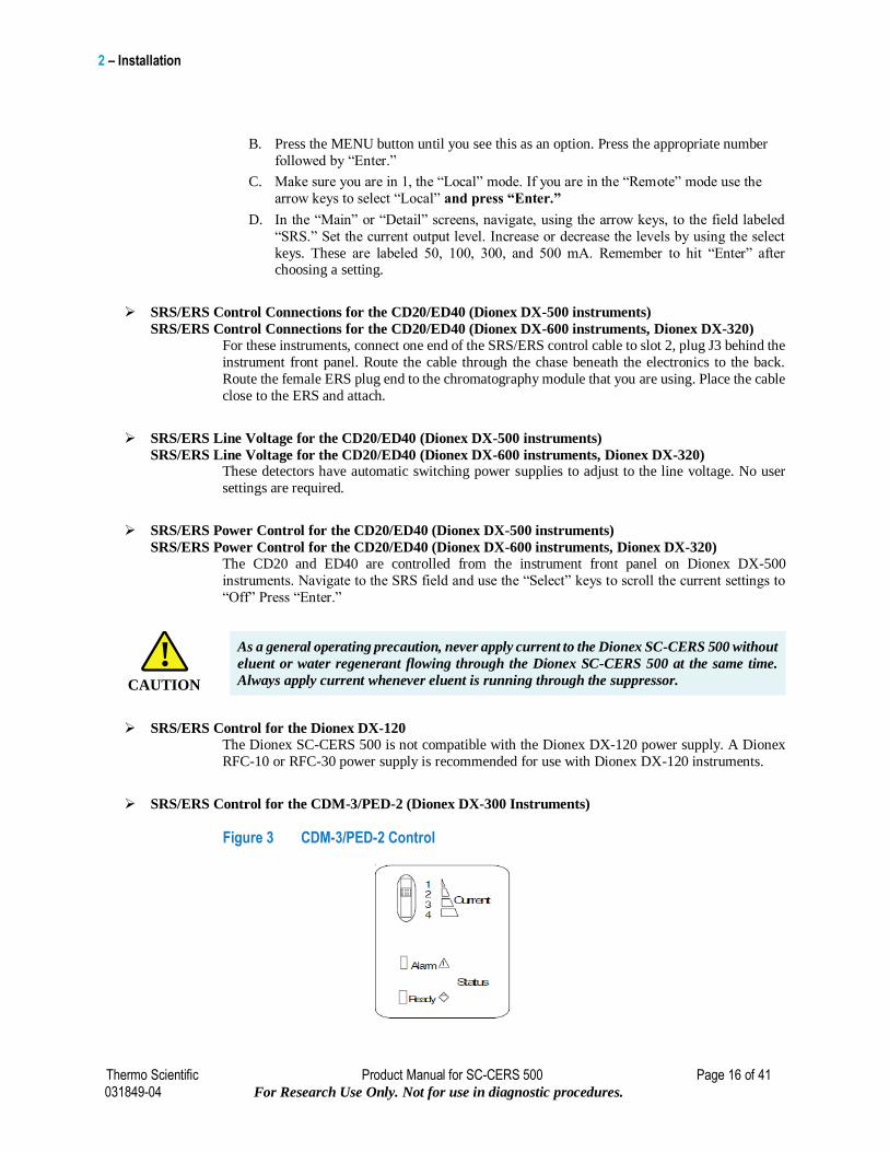
2.2.2 SC20 Suppressor Controller
Figure 4 SC 20 Suppressor Controller
NOTE
!
CAUTION
!
2 – Installation
Thermo Scientific Product Manual for SC-CERS 500 Page 18 of 41 031849-04 For Research Use Only. Not for use in diagnostic procedures.
The SC20 can be used to supply current to the Dionex SC-CERS 500 in 1 mA increments. Refer
to the SC20 manual (Document No. 031768) and Sections 3.3.3, “Dionex SC-CERS 500 Current
Settings,” and Table 5, “Matching the Current Setting and Regenerant Flow Rate to the Eluent
Concentration and Flow Rate for the Dionex SC-CERS 500 in the AutoSuppression External
Water Mode,” in Section 3.4.4 in this manual for more information.
2.2.3 Dionex RFC-10 or Dionex RFC-30 Controller
The Dionex RFC-10 and Dionex RFC-30 units can be used to supply current to the Dionex SC-
CERS 500 in 1 mA increments. Refer to the Reagent-Free Controller Operator’s Manual
(Document # 031880) for detailed instructions. Select the CERS_2MM or CERS_4MM for
Dionex SC-CERS operation and use the current settings for CERS operation.
If using DX 1-03 it is recommended to use a Dionex RFC-10 or Dionex RFC-30 power
supply to provide more accurate current to the Dionex SC-CERS 500
Dionex RFC-30 Line Voltage
The 2-position rotary switch located on the back of the RFC-30 allows the selection of either 110
V or 220 V input line voltage. It can be adjusted with a large flat-bladed screwdriver or a small coin. The unit is not frequency sensitive and will work equally well on 50 or 60 Hz without
adjustment. Each position accepts a wide range of input line voltages.
A. Use the 110 V position for all input line voltages between 85 VAC and 135 VAC.
B. Use the 220 V position for all input line voltages between 175 VAC and 265 VAC.
Dionex RFC-30 Power Control
The control and display panel on the Dionex RFC-30 is located on the front of that module’s
cabinet. LED indicators inform the operator of the system’s operational status.
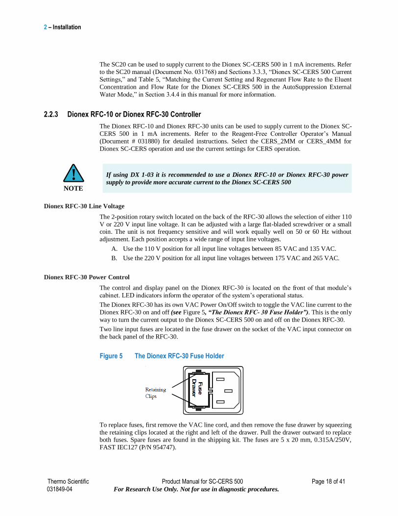
The Dionex RFC-30 has its own VAC Power On/Off switch to toggle the VAC line current to the
Dionex RFC-30 on and off (see Figure 5, “The Dionex RFC- 30 Fuse Holder”). This is the only
way to turn the current output to the Dionex SC-CERS 500 on and off on the Dionex RFC-30.
Two line input fuses are located in the fuse drawer on the socket of the VAC input connector on
the back panel of the RFC-30.
Figure 5 The Dionex RFC-30 Fuse Holder
To replace fuses, first remove the VAC line cord, and then remove the fuse drawer by squeezing
the retaining clips located at the right and left of the drawer. Pull the drawer outward to replace both fuses. Spare fuses are found in the shipping kit. The fuses are 5 x 20 mm, 0.315A/250V,
FAST IEC127 (P/N 954747).
NOTE
!

2 – Installation
Thermo Scientific Product Manual for SC-CERS 500 Page 19 of 41 031849-04 For Research Use Only. Not for use in diagnostic procedures.
It is recommended to use a Dionex RFC-10 or Dionex RFC-30 power supply to provide
more accurate current to the Dionex SC-CERS 500
As a general operating precaution, never apply current to the Dionex SC-CERS 500 without
eluent or water regenerant flowing through the Dionex SC-CERS 500 at the same time.
Always apply current whenever eluent is running through the suppressor.
2.3 Temperature
For applications requiring high temperatures (40°C to 60°C), the Dionex SC-CERS 500 must be
installed outside the chromatography oven; add a length of tubing (up to 20”, 50 cm) between the
column outlet and the suppressor inlet to allow time for the eluent to cool to room temperature if
operating the column above 40°C. Use a minimal length of tubing from the column outlet to the
ELUENT IN port of the Dionex SC-CERS 500 and from the REGEN OUT port to the
conductivity cell. The tubing should have the ends square cut so no dead volume is introduced.
The line from the cell to the REGEN IN port should be 1/8” i.d. to minimize backpressure to the
Dionex SC-CERS 500. When using a temperature controlled chromatography module, a
conductivity cell with a shield (P/N 044132) should be placed inside the oven.
The Conductivity Cell with DS3 (P/N 044130) will not compensate for temperatures above
45°C. Placing the DS3 Cell outside the oven will lead to poor sensitivity since the Dionex
SC-CERS 500 and DS3 are at a lower temperature than the oven.
2.4 Back Pressure Coils
No backpressure coils are required for the Dionex SC-CERS 500 Suppressor operation. Remove
any existing backpressure coils before installing the Dionex SC-CERS 500.
2.5 Gas Separator Waste Tube for the Dionex SC-CERS 500
The Gas Separator Waste Tube (P/N 045460) is an integral part of the Dionex SC-CERS 500
similar to the Cation Electrolytically Regenerated Suppressor (CERS 500) system. Its function is
to ensure the separation of any hydrogen/oxygen gas generated in the Dionex SC-CERS 500
during the electrolytic operation. The Gas Separator Waste Tube is used to avoid concentrating
the gas in the waste container. The Gas Separator Waste Tube is shipped in the ED40, ED50,
ED50A, CD20, CD25, CD25A, Dionex DX-320, and Dionex RFC-30 Ship Kits.
DO NOT CAP THE WASTE RESERVOIR! The very small amount of hydrogen gas
generated by the Dionex SC-CERS 500 is not dangerous unless the gas is trapped in a
closed container and allowed to concentrate. The Gas Separator Waste Tube must be open
to the atmosphere and not in a confined space to operate properly.
NOTE
!
CAUTION
!
CAUTION
!
CAUTION
!
2 – Installation
Thermo Scientific Product Manual for SC-CERS 500 Page 20 of 41 031849-04 For Research Use Only. Not for use in diagnostic procedures.
2.5.1 Assembly
Assemble and install the Gas Separator Waste Tube and waste line following the steps
below. See Figure 6, “The AutoSuppression Recycle Mode Plumbing Diagram.”
A. Use one or two couplers (P/N 045463) to connect two or three lengths of 1/2" ID black
polyethylene tubing (P/N 045462) depending of the depth of your waste container. It is
important that the top of the Waste Separator Tube extend above the top of the Waste container as shown in Figure 6, “The AutoSuppression Recycle Mode Plumbing
Diagram.”
B. Place the Gas Separator Waste Tube with the 1/8" OD tubing attached into the waste
container. Be sure that the bottom of the Gas Separator Waste Tube is resting on the floor
of the waste container, the top of the device (where the white 1/8" OD tubing meets the
black 1/2" OD tubing) is above the top of the container and that the Gas Separator Waste Tube and the waste container are open to the atmosphere
2.6 Electrolytically Regenerated Suppressor Current Selection
On CD20/25/25A, ED50/50A and ED40 detectors in Dionex DX-500, Dionex DX-600, and
Dionex DX-320 instruments, the correct current is set by navigating to the SRS field in the “Main”
menu and using the “Select” keys to change the setting. The read-out is the approximate current
level.
Refer to Sections 3.3.2, “AutoSuppression Recycle Mode Operation,” 3.3.5, “Using a Dionex
RFC-10 Suppressor Controller to Power the Dionex SC-CERS 500,” and 3.4.3 “AutoSuppression
External Water Mode Operation” of this manual for recommended Current settings required for
the chromatographic conditions required in the specific application being performed.
Some general guidelines for setting the Current are noted below.
A. The lower the concentration of the eluent, the lower the current needed for total
suppression. This depends on both the nature of the eluent components and their
concentration.
B. The lower the eluent flow rate, the lower the current required.
C. Too high a current may create unnecessary baseline noise and reduce suppressor lifetime.
D. Less current is required for Dionex SC-CERS 500 (2 mm) than Dionex SC-CERS 500
(4 mm).
E. If background increases over time at a given current setting for a given application,
increase current setting (See Section 4.3, “High Background Conductivity”). The
maximum recommended setting for the Dionex SC-CERS 500 (4 mm) is 300 mA. The maximum recommended setting for the Dionex SC-CERS 500 (2 mm) is 100 mA.
F. If solvent is used in the eluent, use the current setting recommended for electrolytic
suppression of aqueous eluents.
2 – Installation
Thermo Scientific Product Manual for SC-CERS 500 Page 21 of 41 031849-04 For Research Use Only. Not for use in diagnostic procedures.
2.6.1 Power Requirements
The existing SRS/ERS power supply can be used for powering the ES component of the Dionex
SC-CERS 500 device. Choose SRS or ERS as the suppressor option when operating from
Chromeleon, PeakNet, or from the front panel of the instrument.
The ES Component is an electrolytic device and will operate using any SRS/ERS power supply.
The AC Component is a chemical suppressor and hence requires no power.
Always use the recommended currents for a given application. Calculate the optimum current for
your application as described in Section 3.3.3, “Dionex SC-CERS 500 Current Settings,” and set
this current using the ED50A, CD25A or Dionex RFC-10/RFC-30. When using older equipment,
choose the lowest current available. For example, for 4 mm applications (such as 20 mM MSA with CS12A columns or 26 mM MSA with CS16 columns) use 100 mA setting and for 2 mm
applications use 50 mA setting. For other eluent strengths of MSA refer to Section 3.3.3, “Dionex
SC-CERS 500 Current Settings,” for calculating the optimized current setting.
3 – Operation
Thermo Scientific Product Manual for SC-CERS 500 Page 22 of 41 031849-04 For Research Use Only. Not for use in diagnostic procedures.
3. Operation
This section provides instructions for the start-up and operation of the Dionex Salt-Converter Cation Electrolytically Regenerated Suppressor 500 (Dionex SC-CERS 500). The selection and
description of each of the suppression modes of operation are covered.
3.1 Chemical Purity Requirements
Obtaining precise and accurate results requires eluents that are free of ionic impurities. Chemicals
and deionized water used to prepare MSA eluents must be of the purities described below. Water with low trace impurities and low particulate levels in eluents and regenerants also help protect
your Dionex SC-CERS 500 and system components from contamination. Thermo Fisher
Scientific cannot guarantee proper Dionex SC-CERS 500 performance when the quality of the
chemicals and water used to prepare eluents has been compromised.
3.1.1 Inorganic Chemicals
Reagent Grade inorganic chemicals should always be used to prepare ionic eluents. Whenever
possible, inorganic chemicals that meet or surpass the latest American Chemical Society standard
for purity (universally accepted standard for reagents) should be used. These inorganic chemicals
will detail the purity by having an actual lot analysis on each label. Thermo Fisher Scientific
supplies high purity methanesulfonic acid (P/N 033478).
3.1.2 Solvents
Since solvents used with the Dionex SC-CERS 500 are added to ionic eluents to modify the ion
exchange process or improve sample solubility, the solvents used must be free of ionic impurities.
However, since most manufacturers of solvents do not test for ionic impurities, it is important that
the highest grade of solvents available be used. Currently, several manufacturers are making
“Ultrahigh” purity solvents that are compatible for HPLC and spectrophotometric applications.
These “ultrahigh” purity solvents will usually ensure that your chromatography is not affected by
ionic impurities in the solvent. Currently at Thermo Fisher Scientific, we have obtained consistent
results using High Purity Solvents manufactured by Burdick and Jackson and Optima® Solvents
manufactured by Fisher Scientific.
3.1.3 Deionized Water
The deionized water used to prepare eluents should be degassed Type I Reagent Grade Water with
a specific resistance of 18.2 megohm-cm. The water used for the AutoSuppression External Water
Mode should have a specific resistance of 18.2 megohm-cm. The deionized water should be free
of ionized impurities, organics, microorganisms and particulate matter larger than 0.2 μm. It is
good practice to filter eluents through a 0.2 μm filter whenever possible. Bottled HPLC-Grade
Water should not be used since most bottled water contains an unacceptable level of ionic
impurities. Finally, thoroughly degas all deionized water prior to preparing any eluents or
regenerants.
3 – Operation
Thermo Scientific Product Manual for SC-CERS 500 Page 23 of 41 031849-04 For Research Use Only. Not for use in diagnostic procedures.
3.2 Installation and Start-Up
The Dionex SC-CERS 500 is installed in the column compartment of the chromatography module
right after the analytical column and before the conductivity detector cell. On the Dionex DX-
600, Dionex DX-500, Dionex DX-320, Dionex ICS-1000, Dionex ICS-1500, Dionex ICS-2000,
Dionex ICS-2100, Dionex ICS-2500, Dionex ICS-3000, Dionex ICS-5000, Dionex ICS-5000+
and Dionex Integrion instruments, the Dionex SC-CERS 500 mounts on tabs on the component
panel.
On the Dionex ICS-3000, Dionex ICS-5000, and the Dionex ICS-5000+, the Dionex SC-CERS
500 ES mounts on the CD in the DC module; the Dionex SC-CERS 500 AS mounts on the
suppressor plate of the second detector console (if fitted), or in the top section of the upper
compartment.
On the Dionex ICS-2100, Dionex ICS-2000, Dionex ICS-1600, Dionex ICS-1500, Dionex ICS-
1100 and Dionex ICS-1000, the Dionex SC-CERS 500 ES mounts on the vertical suppressor
brackets between the CD cell and column in the component panel; the Dionex SC-CERS 500 AS
mounts on the horizontal suppressor brackets at the top of the component panel.
On the Dionex Integrion the Dionex SC-CERS 500 ES mounts on the tangs in the detector
compartment; the Dionex SC-CERS 500 AS need to be affixed next to the ES in the detector
compartment using double sided tape or Velcro.
Orient the Dionex SC-CERS 500 with the ELUENT IN port and the cable at the top; align the slots on the back of the Dionex SC-CERS 500 with the tabs on the panel. Press in, and then down,
to lock the Dionex SC-CERS 500 in place. Lift up, then pull out to remove the Dionex SC-CERS
500. Make sure the Dionex SC-CERS 500 is plumbed properly, according to the selected mode
of operation. Refer to Section 2, “Installation,” for complete installation instructions.
The membranes and screens in the Dionex SC-CERS 500 must be completely hydrated to
maintain liquid seals and chromatographic performance. This requirement is achieved by
maintaining the regenerant chambers full of the appropriate regenerant solution when in
operation or full of water during storage. This will ensure that the membranes and screens
remain properly hydrated.
3.2.1 Dionex SC-CERS 500 Regeneration Instructions
Complete the following steps before installing the Dionex SC-CERS 500 for the first time or after
storage of the suppressor.
3.2.1.1 ES - Eluent Suppressor Regeneration
A. Disconnect the lines to the component labeled Eluent Suppressor.
B. Attach a temporary waste line from the ELUENT IN port to a waste container.
C. Use a disposable plastic syringe push approximately 3 ml of 200 mN NaOH through the
ELUENT OUT port.
D. Attach a temporary waste line from the REGEN OUT port to a waste container.
E. Push approximately 5 ml of 200 mN NaOH through the REGEN IN port.
F. Allow the ES component to sit for approximately 20 minutes to fully hydrate the
suppressor membranes and screens.
G. Displace the 200 mN NaOH by pushing 3 mL of DI water through the ELUENT OUT
port and 5 mL of DI water through the REGEN IN port.
CAUTION
!
3 – Operation
Thermo Scientific Product Manual for SC-CERS 500 Page 24 of 41 031849-04 For Research Use Only. Not for use in diagnostic procedures.
3.2.1.2 AC - Analyte Converter Regeneration
A. Disconnect the lines to the component labeled Analyte Converter.
B. Attach a temporary waste line from the ELUENT IN port to a waste container.
C. Use a disposable plastic syringe push approximately 3 mL of 200 mN MSA through the
ELUENT OUT port.
D. Attach a temporary waste line from the REGEN OUT port to a waste container.
E. Push approximately 5 mL of 200 mN MSA through the REGEN IN port.
F. Allow the AC component to sit for approximately 20 minutes to fully hydrate the
suppressor membranes and screens.
G. Displace the 200 mN MSA by pushing 3 mL of DI water through the ELUENT OUT
port and 5 mL of DI water through the REGEN IN port.
DO NOT CAP THE WASTE RESERVOIR! The very small amount of hydrogen gas
generated by the Dionex SC-CERS 500 is not dangerous unless the gas is trapped in a
closed container and allowed to accumulate. The Gas Separator Waste Tube must be open
to the atmosphere and not in a confined space to operate properly.
Follow Regeneration and then:
A. Mount the suppressors and plug in the ES power cable. Plumb the Dionex SC-CERS 500
components according to the mode of operation. See Sections 3.3 - 3.4.
B. Turn on the power to the Dionex SC-CERS 500 and establish eluent flow through the
Dionex SC-CERS 500. Be sure to turn on the SRS or ERS Control power and the pump
flow at the same time.
Always turn the pump and the SRS/ERS Control on and off at the same time!
Eluent flow through the Dionex SC-CERS 500 is required for proper operation. However,
without current, the membranes and screens in the Dionex SC-CERS 500 will become
expended of regeneration ions by the flowing eluent, resulting in small analyte peak areas.
If this should occur, perform the procedure outlined in Section 4.5, “Decreased
Sensitivity.”
C. Start operation. Allow the system to equilibrate before beginning analysis.
CAUTION
!
CAUTION
!
CAUTION
!
3 – Operation
Thermo Scientific Product Manual for SC-CERS 500 Page 25 of 41 031849-04 For Research Use Only. Not for use in diagnostic procedures.
3.2.2 Dionex SC-CERS 500 Quick Start Instructions
Complete the following steps before installing the Dionex SC-CERS 500 for the first time or after
storage of the suppressor.
3.2.2.1 ES - Eluent Suppressor Quick Start
A. Disconnect the lines to the component labeled Eluent Suppressor.
B. Attach a temporary waste line from the ELUENT IN port to a waste container.
C. Use a disposable plastic syringe push approximately 3 mL of deionized water through
the ELUENT OUT port.
D. Attach a temporary waste line from the REGEN OUT port to a waste container.
E. Push approximately 5 mL of deionized water through the REGEN IN port.
F. Allow the ES component to sit for approximately 20 minutes to fully hydrate the
suppressor membranes and screens.
3.2.2.2 AC - Analyte Converter Quick Start
A. Disconnect the lines to the component labeled Analyte Converter.
B. Attach a temporary waste line from the ELUENT IN port to a waste container.
C. Use a disposable plastic syringe push approximately 3 mL of deionized water through
the ELUENT OUT port.
D. Attach a temporary waste line from the REGEN OUT port to a waste container.
E. Push approximately 5 mL of deionized water through the REGEN IN port.
F. Allow the AC component to sit for approximately 20 minutes to fully hydrate the
suppressor membranes and screens.
3.2.3 Installing the Dionex SC-CERS 500
A. BACK PRESSURE COILS
No Backpressure coils are required for the Dionex SC-CERS 500 suppressor operation.
Remove all existing backpressure coils and long lengths of tubing leading into the
conductivity cell.
B. WASTE LINE
Assemble and install the Gas Separator Waste Tube and the waste line as directed in
Section 2.5.1.
C. INSTALLATION OF THE DIONEX SALT-CONVERTER CATION ELECTROLYTICALLY REGENERATED SUPPRESSOR 500 (DIONEX SC-CERS
500)
Install the two Regenerated Dionex SC-CERS 500 components (ES and AC
components) using the lines and fittings shipped with the Dionex SC-CERS 500. For
more detailed instructions, consult Section 3.3, Figure 6, "The AutoSuppression
Recycle Mode Plumbing Diagram" or see Section 3.4, Figure 7, "The AutoSuppression
External Water Mode Plumbing Diagram.
3 – Operation
Thermo Scientific Product Manual for SC-CERS 500 Page 26 of 41 031849-04 For Research Use Only. Not for use in diagnostic procedures.
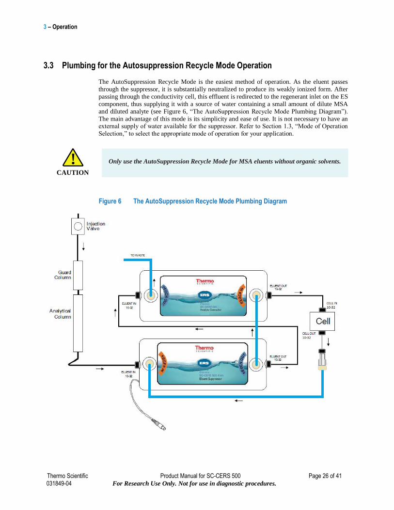
3.3 Plumbing for the Autosuppression Recycle Mode Operation
The AutoSuppression Recycle Mode is the easiest method of operation. As the eluent passes
through the suppressor, it is substantially neutralized to produce its weakly ionized form. After
passing through the conductivity cell, this effluent is redirected to the regenerant inlet on the ES
component, thus supplying it with a source of water containing a small amount of dilute MSA
and diluted analyte (see Figure 6, “The AutoSuppression Recycle Mode Plumbing Diagram”).
The main advantage of this mode is its simplicity and ease of use. It is not necessary to have an external supply of water available for the suppressor. Refer to Section 1.3, “Mode of Operation
Selection,” to select the appropriate mode of operation for your application.
Only use the AutoSuppression Recycle Mode for MSA eluents without organic solvents.
Figure 6 The AutoSuppression Recycle Mode Plumbing Diagram
CAUTION
!

3 – Operation
Thermo Scientific Product Manual for SC-CERS 500 Page 27 of 41 031849-04 For Research Use Only. Not for use in diagnostic procedures.
3.3.1 Eluent Flow Path Connections in the AutoSuppression Recycle Mode
Depending on the specific components (analytical column, conductivity cell) in the system, 1/4-
28 or 10-32 ferrule/bolt liquid lines may be required. All necessary tubing and fittings are supplied
in the system, detector, Dionex RFC-10 or Dionex RFC-30 Ship Kits. To purchase or assemble
1/4-28 or 10-32 ferrule/bolt liquid lines, refer to, “DIONEX Liquid Line Fittings” (P/N 031432).
Always use 0.005" ID PEEK tubing with 10-32 ferrule/bolt fittings on 2 mm systems. Use 0.010"
ID PEEK tubing with 10-32 ferrule/bolt fittings on 4 mm systems.
Install the Dionex SC-CERS 500 in the Chromatography Module as described in Section 2.1,
“System Requirements”.
3.3.1.1 Plumbing
The Dionex SC-CERS 500 comes pre-plumbed and the detailed plumbing schematic is shown in
Figure 6.
A. The column outlet should be connected to the line labeled “Column Out.”
B. The line labeled “Cell in” should be connected to the conductivity cell inlet.
C. Do not connect any backpressure coils or additional tubing that may add backpressure
to the conductivity cell. Remove all preinstalled tubing and backpressure coils.
D. The line from the conductivity cell should be connected using a coupler to an 1/8" line
labeled “Cell Out”. An 1/8" waste line should be connected to the port labeled “To
Waste.” Do not use 1/16" black/colored tubing for the waste line because this tubing
adds backpressure to the device.
E. Install a gas separator waste tube at the end of the waste line.
3.3.2 AutoSuppression Recycle Mode Operation
The Eluent Suppressor in the Dionex SC-CERS 500 uses dilute MSA and electrolysis as the
regenerant and has the ability to provide continuous suppression. See Section 3.3.3.3.
“Recommended Current Settings” to determine the correct amount of current that should be
applied to a Dionex SC-CERS 500. Always operate the Dionex SC-CERS 500 at the lowest
current setting that will suppress the eluent. Increasing the current setting will not improve the
performance and could damage the suppressor. The operation of the Dionex SC-CERS 500
requires a constant flow of the water over the membrane, in a direction that is concurrent to the
flow of the eluent.
In the AutoSuppression Recycle Mode, the eluent leaving the conductivity cell is recycled through
the regenerant chambers as the water supply. This eliminates the need for an external regenerant
water supply. See Figure 6, “The AutoSuppression Recycle Mode Plumbing Diagram.” When the Dionex SC-CERS 500 is operating in this mode, the amount of water flowing through the
regenerant chambers is limited to the eluent flow rate. Because of this limitation, the
AutoSuppression Recycle Mode cannot be used with eluents containing organic solvents. The
Dionex SC-CERS 500 should be operated in the AutoSuppression External Water Mode for
eluents containing organic solvents
3 – Operation
Thermo Scientific Product Manual for SC-CERS 500 Page 28 of 41 031849-04 For Research Use Only. Not for use in diagnostic procedures.
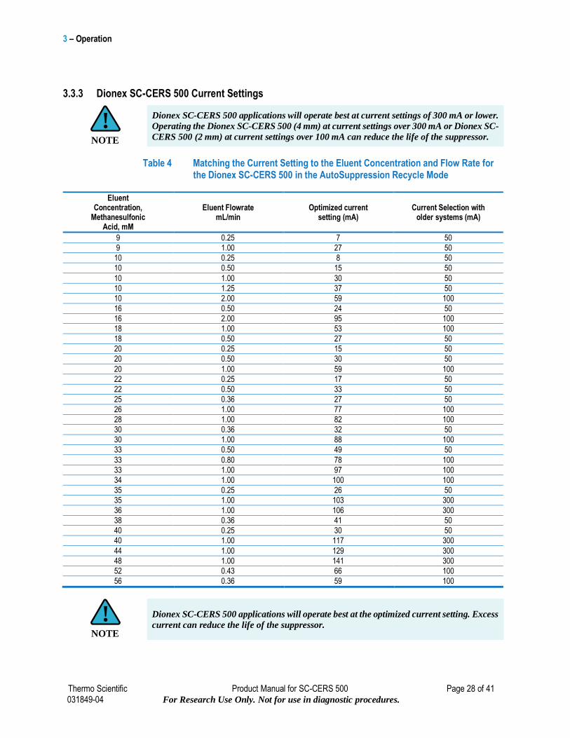
3.3.3 Dionex SC-CERS 500 Current Settings
Dionex SC-CERS 500 applications will operate best at current settings of 300 mA or lower.
Operating the Dionex SC-CERS 500 (4 mm) at current settings over 300 mA or Dionex SC-
CERS 500 (2 mm) at current settings over 100 mA can reduce the life of the suppressor.
Table 4 Matching the Current Setting to the Eluent Concentration and Flow Rate for the Dionex SC-CERS 500 in the AutoSuppression Recycle Mode
Eluent Concentration,
Methanesulfonic Acid, mM
Eluent Flowrate mL/min
Optimized current setting (mA)
Current Selection with older systems (mA)
9 0.25 7 50
9 1.00 27 50
10 0.25 8 50
10 0.50 15 50
10 1.00 30 50
10 1.25 37 50
10 2.00 59 100
16 0.50 24 50
16 2.00 95 100
18 1.00 53 100
18 0.50 27 50
20 0.25 15 50
20 0.50 30 50
20 1.00 59 100
22 0.25 17 50
22 0.50 33 50
25 0.36 27 50
26 1.00 77 100
28 1.00 82 100
30 0.36 32 50
30 1.00 88 100
33 0.50 49 50
33 0.80 78 100
33 1.00 97 100
34 1.00 100 100
35 0.25 26 50
35 1.00 103 300
36 1.00 106 300
38 0.36 41 50
40 0.25 30 50
40 1.00 117 300
44 1.00 129 300
48 1.00 141 300
52 0.43 66 100
56 0.36 59 100
Dionex SC-CERS 500 applications will operate best at the optimized current setting. Excess
current can reduce the life of the suppressor.
NOTE
!
NOTE
!
3 – Operation
Thermo Scientific Product Manual for SC-CERS 500 Page 29 of 41 031849-04 For Research Use Only. Not for use in diagnostic procedures.
3.3.3.1 ERS Maximum Current Setting
To ensure the optimal performance of the Dionex SC-CERS 500, avoid applying excess current
to the suppressors. Excess operation currents lead to excess heat generation, which can reduce the
suppressor lifetime and cause higher chromatographic baseline noise. The maximum operating
current and recommended current settings for the Dionex SC-CERS 500 can be calculated using
the equations below:
3.3.3.2 Maximum Operating Current
Dionex SC-CERS 500 (4 mm) – Do not exceed 300 mA
Maximum Current (mA) = sum of eluent concentration (mN) * flow rate (ml/min) * 4
Dionex SC-CERS 500 (2 mm) – Do not exceed 100 mA
Maximum Current (mA) = sum of eluent concentration (mN) * flow rate (ml/min) * 4
3.3.3.3 Recommended Current Settings
The following equations determine the correct amount of current that should be applied to a
Dionex SC-CERS 500 based on the eluent concentration (mN) and flow rate (mL/min) for an
application.
Dionex SC-CERS 500 (4 mm)
Operating Current (mA) = sum of eluent concentration (mN) * flow rate (mL/min) * 2.924
Dionex SC-CERS 500 (2 mm)
Operating Current (mA) = sum of eluent concentration (mN) * flow rate (mL/min) * 2.924
3.3.3.4 Maximum Suppression Capacity
Sum of Eluent Concentration Calculation
When using the Dionex SC-CERS 500 (4 mm) and Dionex SC-CERS 500 (2 mm), the sum of the
eluent concentration can be calculated using the equation below:
Sum of eluent concentration (mN) = MSA (mM)
3.3.4 Using Thermo Scientific PeakNet 6.4 to Power the Dionex SC-CERS 500
For optimal suppressor performance, it is important to use the recommended suppressor currents
for the target applications. The Program Wizard of the Dionex Chromatography Management
System (see Control Programmed Program Wizard) guides you in setting the recommended
current for the Dionex SC-CERS 500. The Wizard supplies a recommended current based on the
eluent concentration and flow rate settings (See Section 3.3.3.3. “Recommended Current
Settings” to determine the correct amount of current that should be applied to a Dionex SC-CERS
500.). The Dionex Chromatography Management System automatically enters the recommended
current into the Program and applies that current to the Dionex SC-CERS 500. When setting the
current to the Dionex SC-CERS 500 using the Chromeleon Wizard, choose CERS as the
suppressor type.
In Chromeleon, the suppressor current could also be entered manually by editing the
program file. For calculating the current manually, refer to the Section 3.3.3, “Dionex SC-
CERS 500 Current Settings.”
NOTE
!
3 – Operation
Thermo Scientific Product Manual for SC-CERS 500 Page 30 of 41 031849-04 For Research Use Only. Not for use in diagnostic procedures.
3.3.5 Using a Dionex RFC-10 or Dionex RFC-30 Power Supply to Power the Dionex SC-CERS 500
See the Reagent-Free Controller Manual for details instructions.
3.4 Plumbing for the Auto Suppression External Water Mode Operation
Any analysis that can be performed using the AutoSuppression Recycle Mode can be done using
the AutoSuppression External Water Mode, however for eluents that do not contain any
solvents the AutoSuppression Recycle Mode is preferred. A constant source of deionized water
having a specific resistance of 10 megohm or greater, is supplied to the regenerant chambers to
generate hydroxide ions for neutralization. Refer to Section 1.3, “Mode of Operation Selection,”
to select the appropriate mode of operation for your application.
The AutoSuppression External Water Mode must be used whenever organic solvents up to
40% are present in the eluent.
3.4.1 Eluent Flow Path Connections in the AutoSuppression External Water Mode
Depending on the specific components (analytical column, conductivity cell) in the system, 1/4-
28 or 10-32 ferrule/bolt liquid lines may be required. All necessary tubing and fittings are supplied
in the detector or Dionex RFC-10 or Dionex RFC-30 Ship Kits. To purchase or assemble 1/4-28
or 10-32 ferrule/bolt liquid lines, refer to, “DIONEX Liquid Line Fittings” (P/N 031432). Always use 0.005" ID PEEK tubing with 10-32 ferrule/bolt fittings on 2 mm systems. Use 0.010" ID
PEEK tubing with 10-32 ferrule/bolt fittings on 4 mm systems.
Install the Dionex SC-CERS 500 in the Chromatography Module as described in Section 2.1,
“System Requirements”.
3.4.1.1 Plumbing
The Dionex SC-CERS 500 comes pre-plumbed and the detailed plumbing schematic is shown in
Figure 7, “The AutoSuppression External Water Mode Plumbing Diagram.”
A. The column outlet should be connected to the line labeled “Column Out.”
B. The line labeled “Cell in” should be connected to the conductivity cell inlet.
C. Do not connect any backpressure coils or additional tubing that may add backpressure
to the conductivity cell. Remove all preinstalled tubing and backpressure coils.
D. The line from the conductivity cell should be connected using a coupler to an 1/8" waste
line and diverted to waste.
No backpressure is required for the Dionex SC-CERS 500 suppressor. Remove any
backpressure coils, if present.
CAUTION
!
CAUTION
!
3 – Operation
Thermo Scientific Product Manual for SC-CERS 500 Page 31 of 41 031849-04 For Research Use Only. Not for use in diagnostic procedures.
3.4.2 Regenerant Flow Path Connections in the AutoSuppression External Water Mode Using the Pressurized Water Delivery System
The External Regenerant Installation Kit (P/N 038018) contains all of the components needed to
install and operate the Dionex SC-CERS 500 with a pressurized water reservoir. The kit contains
one 4-L bottle, one pressure regulator (0-30 psi/0-210 KPa) and appropriate tubing (P/N 039164).
A. Make the following air line connections:
1. Locate the pieces of tinted 1/8" OD plastic tubing (P/N 050089) supplied in the
Installation Parts Kit.
2. Push the end of one piece of 1/8" OD tubing over the barbed fitting of the regulator.
Connect the other end of the tubing to the source of air pressure.
3. Push one end of the second piece of 1/8" OD tubing over the other barbed fitting of
the regulator. Push the other end of this tubing over the barbed fitting (P/N 050077)
in the pressure inlet of the plastic reservoir. (See Figure 7, “The AutoSuppression
External Water Mode Plumbing Diagram”).
B. Make the following water line connections. See Figure 7, “The AutoSuppression
External Water Mode Plumbing Diagram.”
1. Use a coupler (P/N 039056) to connect one end of the 30" tubing assembly (P/N 035727) that comes in the Installation Kit to the water reservoir. Connect the other
end of this tubing to the REGEN IN port of the Eluent Suppressor component of the
Dionex SC-CERS 500.
2. Using a coupler (P/N 039056) and a 1/8" OD piece of tubing (P/N 035728) from the
Installation Kit, connect one end of this line to the waste port of the Dionex SC-
CERS 500 and then connect the other end of the line to the Gas Separator Waste Tube.
C. Fill the water source reservoir. Make sure that the O-ring is inside the cap of the reservoir
before screwing the cap onto the reservoir. Screw the cap onto the reservoir tightly and
place the reservoir near the Chromatography Module.
D. With no current applied, use the air pressure gauge to adjust the external water flow rate
to approximately 3-5 mL/ min for the Dionex SC-CERS 500 (4 mm) and 1-2 mL/min
for the Dionex SC-CERS 500 (2 mm). The external water flow rate is controlled by two
factors: the pressure applied to the water reservoir (0-25 psi) and the current setting on
the Electrolytically Regenerated Suppressor Control unit. After the current is applied,
the flow rate will drop due to gas formation in the regenerant chambers and the pressure
must then be adjusted to give the correct flow rate at the specific current setting required
for the application. See Section 3.4.3, “AutoSuppression External Water Mode Operation.”
A safety relief valve on the reservoir regulator prevents pressure greater than 25 psi from
being applied to the water reservoir.
NOTE
!
3 – Operation
Thermo Scientific Product Manual for SC-CERS 500 Page 32 of 41 031849-04 For Research Use Only. Not for use in diagnostic procedures.
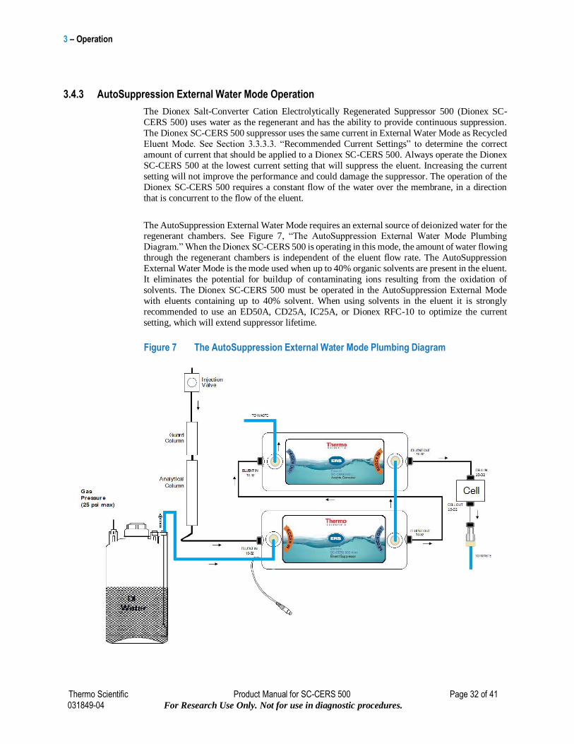
3.4.3 AutoSuppression External Water Mode Operation
The Dionex Salt-Converter Cation Electrolytically Regenerated Suppressor 500 (Dionex SC-
CERS 500) uses water as the regenerant and has the ability to provide continuous suppression.
The Dionex SC-CERS 500 suppressor uses the same current in External Water Mode as Recycled
Eluent Mode. See Section 3.3.3.3. “Recommended Current Settings” to determine the correct
amount of current that should be applied to a Dionex SC-CERS 500. Always operate the Dionex
SC-CERS 500 at the lowest current setting that will suppress the eluent. Increasing the current
setting will not improve the performance and could damage the suppressor. The operation of the
Dionex SC-CERS 500 requires a constant flow of the water over the membrane, in a direction
that is concurrent to the flow of the eluent.
The AutoSuppression External Water Mode requires an external source of deionized water for the regenerant chambers. See Figure 7, “The AutoSuppression External Water Mode Plumbing
Diagram.” When the Dionex SC-CERS 500 is operating in this mode, the amount of water flowing
through the regenerant chambers is independent of the eluent flow rate. The AutoSuppression
External Water Mode is the mode used when up to 40% organic solvents are present in the eluent.
It eliminates the potential for buildup of contaminating ions resulting from the oxidation of
solvents. The Dionex SC-CERS 500 must be operated in the AutoSuppression External Mode
with eluents containing up to 40% solvent. When using solvents in the eluent it is strongly
recommended to use an ED50A, CD25A, IC25A, or Dionex RFC-10 to optimize the current
setting, which will extend suppressor lifetime.
Figure 7 The AutoSuppression External Water Mode Plumbing Diagram
3 – Operation
Thermo Scientific Product Manual for SC-CERS 500 Page 33 of 41 031849-04 For Research Use Only. Not for use in diagnostic procedures.
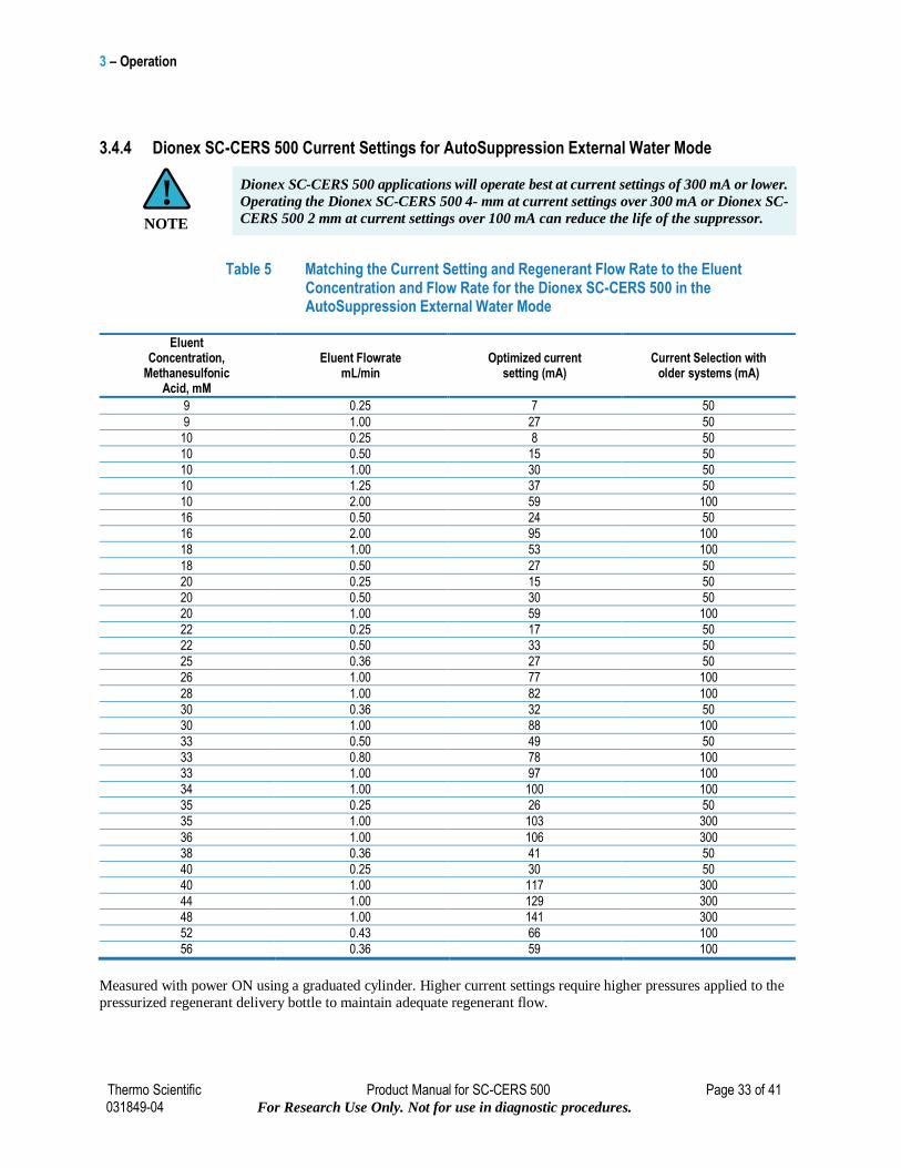
3.4.4 Dionex SC-CERS 500 Current Settings for AutoSuppression External Water Mode
Dionex SC-CERS 500 applications will operate best at current settings of 300 mA or lower.
Operating the Dionex SC-CERS 500 4- mm at current settings over 300 mA or Dionex SC-
CERS 500 2 mm at current settings over 100 mA can reduce the life of the suppressor.
Table 5 Matching the Current Setting and Regenerant Flow Rate to the Eluent Concentration and Flow Rate for the Dionex SC-CERS 500 in the AutoSuppression External Water Mode
Eluent Concentration,
Methanesulfonic Acid, mM
Eluent Flowrate mL/min
Optimized current setting (mA)
Current Selection with older systems (mA)
9 0.25 7 50
9 1.00 27 50
10 0.25 8 50
10 0.50 15 50
10 1.00 30 50
10 1.25 37 50
10 2.00 59 100
16 0.50 24 50
16 2.00 95 100
18 1.00 53 100
18 0.50 27 50
20 0.25 15 50
20 0.50 30 50
20 1.00 59 100
22 0.25 17 50
22 0.50 33 50
25 0.36 27 50
26 1.00 77 100
28 1.00 82 100
30 0.36 32 50
30 1.00 88 100
33 0.50 49 50
33 0.80 78 100
33 1.00 97 100
34 1.00 100 100
35 0.25 26 50
35 1.00 103 300
36 1.00 106 300
38 0.36 41 50
40 0.25 30 50
40 1.00 117 300
44 1.00 129 300
48 1.00 141 300
52 0.43 66 100
56 0.36 59 100
Measured with power ON using a graduated cylinder. Higher current settings require higher pressures applied to the
pressurized regenerant delivery bottle to maintain adequate regenerant flow.
NOTE
!
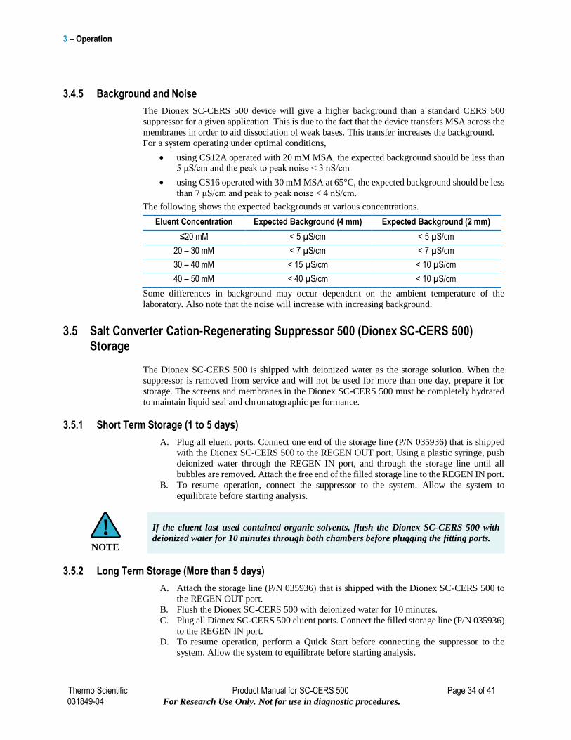
3 – Operation
Thermo Scientific Product Manual for SC-CERS 500 Page 34 of 41 031849-04 For Research Use Only. Not for use in diagnostic procedures.
3.4.5 Background and Noise
The Dionex SC-CERS 500 device will give a higher background than a standard CERS 500
suppressor for a given application. This is due to the fact that the device transfers MSA across the
membranes in order to aid dissociation of weak bases. This transfer increases the background.
For a system operating under optimal conditions,
using CS12A operated with 20 mM MSA, the expected background should be less than 5 μS/cm and the peak to peak noise < 3 nS/cm
using CS16 operated with 30 mM MSA at 65°C, the expected background should be less
than 7 μS/cm and peak to peak noise < 4 nS/cm.
The following shows the expected backgrounds at various concentrations.
Eluent Concentration Expected Background (4 mm) Expected Background (2 mm)
≤20 mM < 5 µS/cm < 5 µS/cm
20 – 30 mM < 7 µS/cm < 7 µS/cm
30 – 40 mM < 15 µS/cm < 10 µS/cm
40 – 50 mM < 40 µS/cm < 10 µS/cm
Some differences in background may occur dependent on the ambient temperature of the
laboratory. Also note that the noise will increase with increasing background.
3.5 Salt Converter Cation-Regenerating Suppressor 500 (Dionex SC-CERS 500) Storage
The Dionex SC-CERS 500 is shipped with deionized water as the storage solution. When the
suppressor is removed from service and will not be used for more than one day, prepare it for
storage. The screens and membranes in the Dionex SC-CERS 500 must be completely hydrated
to maintain liquid seal and chromatographic performance.
3.5.1 Short Term Storage (1 to 5 days)
A. Plug all eluent ports. Connect one end of the storage line (P/N 035936) that is shipped
with the Dionex SC-CERS 500 to the REGEN OUT port. Using a plastic syringe, push
deionized water through the REGEN IN port, and through the storage line until all
bubbles are removed. Attach the free end of the filled storage line to the REGEN IN port.
B. To resume operation, connect the suppressor to the system. Allow the system to
equilibrate before starting analysis.
If the eluent last used contained organic solvents, flush the Dionex SC-CERS 500 with
deionized water for 10 minutes through both chambers before plugging the fitting ports.
3.5.2 Long Term Storage (More than 5 days)
A. Attach the storage line (P/N 035936) that is shipped with the Dionex SC-CERS 500 to
the REGEN OUT port.
B. Flush the Dionex SC-CERS 500 with deionized water for 10 minutes.
C. Plug all Dionex SC-CERS 500 eluent ports. Connect the filled storage line (P/N 035936)
to the REGEN IN port. D. To resume operation, perform a Quick Start before connecting the suppressor to the
system. Allow the system to equilibrate before starting analysis.
NOTE
!
4 – Troubleshooting Guide
Thermo Scientific Product Manual for SC-CERS 500 Page 35 of 41 031849-04 For Research Use Only. Not for use in diagnostic procedures.
4. Troubleshooting Guide
The purpose of the Troubleshooting Guide is to help you solve operating problems that may arise while using the Dionex Salt-Converter Cation Electrolytically Regenerated Suppressor 500
(Dionex SC-CERS 500). For more information on problems that originate with the Ion
Chromatograph or the specific cation exchange column set in use, refer to the Troubleshooting
Guide in the appropriate Installation Manual. If you cannot solve the problem on your own,
contact the Thermo Scientific Regional Office nearest you (see, “Thermo Scientific Worldwide
Offices”).
DO NOT allow eluent to flow through the Dionex SC-CERS 500 without the power turned
on. Doing so will cause noticeable anomalous analyte peak areas. If this should occur,
perform the procedure outlined in Section 4.4.2, “Nonlinear Response or Loss of
Sensitivity.”
4.1 Electrolytically Regenerated Suppressor Operational Status Displays
4.1.1 Alarm State for ED50A, CD25A, and IC25A (Dionex DX-600 System with Chromeleon 6.2 SP2 or later)
ED50A, CD25A, and IC25A modules in Dionex DX-600 systems equipped with Chromeleon 6.2
SP2 or later chromatography workstation provides full operation control to the Dionex SC-CERS
500. When using these modules, the suppressor type and current setting will be shown on the
module front panel.
The error message, “Open circuits are detected from the suppressor.” This may be caused by incorrect identification of the suppressor being used or the suppressor is damaged. To prevent this
alarm state, make sure that (1) the SRS cable is connected properly to the Dionex SC-CERS 500
suppressor, (2) the CERS suppressor type is selected, and (3) the eluent flow is on. If the problem
persists, it is possible that the Dionex SC-CERS 500 suppressor is damaged or fouled. See Section
5, “Dionex SC-CERS 500 Cleanup.” Check and ensure the is identified as a CERS suppressor.
4.1.2 Dionex RFC-10 Suppressor Controller is “Not Enabled” for Dionex DX-600, Dionex DX-500, and Dionex DX-320 Operation
The Dionex RFC-10 suppressor controller is required to operate the Dionex SC-CERS 500 in IC
systems without Chromeleon and a Dionex ICS system with suppressor power supply. Refer to the Dionex RFC-10 operator's manual for details on its installation and operation.
When the Dionex RFC-10 module status says “not enabled” even through the pump is on, perform
the following steps to solve the problem:
A. Check the TTL-2 OUT connector for a loose wire.
B. Check that the pump TTL2 output is set to 0 Flow in the Pump Options screen.
CAUTION
!
4 – Troubleshooting Guide
Thermo Scientific Product Manual for SC-CERS 500 Page 36 of 41 031849-04 For Research Use Only. Not for use in diagnostic procedures.
4.1.3 Alarm States for the CD20/ED40 (Dionex DX-500 Instruments)
When using these detectors, the power setting will be shown on the screen when the ERS is on.
The SRS/ERS cable must be connected to the ERS and conductive liquid must be flowing to
prevent an alarm state.
When the SRS/ERS Control unit is in shutdown mode after detecting a malfunction in the system,
an alarm message “SRS Alarm” will flash on the screen. To determine the cause, press “Menu,” proceed to the “Diagnostic Menu” and press “Analog Status.” On the left side of the screen, two
fields give the SRS/ERS status as shown below:
SRS CONNECTED: Y (or N) This indicates that the Dionex SC-CERS 500 is connected. If it
shows “N,” connect the SRS/ERS cable.
SRS OVER VOLT: N (or Y) This indicates whether the Dionex SC-CERS 500 has a voltage
higher than the upper limit (7.5 to 8 V). Try lowering the power setting on the front panel.
4.2 Suppressor High Voltage Error Message
A. Verify that the Dionex SC-CERS 500 is connected to the power supply and the current
is set properly (per Section 3.3.3).
B. The Electrolytically Regenerated Suppressor does not support electrolysis: There is no
conductive liquid in the eluent and/or the regenerant chamber(s). Causes of this
malfunction may include the following:
1. Lack of eluent and regenerant flow.
2. Plugged or leaking tubing.
3. Plugged or leaking or fittings
4. Lack of pneumatic pressure on the eluent or water bottles in the AutoSuppression
External Water Mode.
5. Empty eluent or water bottles.
6. Analytical pump is not operating.
7. Eluent is non-ionic liquid.
4.3 High Background Conductivity
A. Check that the DIONEX SC-CERS is operating at the correct current (per Section 3.3.3), and that there are no suppressor alarms..
B. Check for eluent flow out of the ELUENT OUT port of the Eluent Suppressor component
of the Dionex SC-CERS 500.
1. If there is no flow out of the ELUENT OUT port, make sure that eluent is entering
the Dionex SC-CERS 500 at the ELUENT IN port. If there is no flow at this point,
trace the eluent flow path backward through the system to find and remove the
blockage.
2. If there is flow into the Dionex SC-CERS 500 but not out, and there are no visible
leaks from the side seam of the suppressor, a break in the membrane is probably
allowing eluent to leak into the regenerant chambers. If this is the case, then the
Dionex SC-CERS 500 must be replaced. The Dionex SC-CERS 500 is sealed during
manufacture. Attempting to open it will destroy it.
3. If there is flow into and out of the Eluent Suppressor, then check the Analyte
Converter for eluent flow out by following the above steps outlined in B.1 and B.2.
4 – Troubleshooting Guide
Thermo Scientific Product Manual for SC-CERS 500 Page 37 of 41 031849-04 For Research Use Only. Not for use in diagnostic procedures.
DO NOT ATTEMPT TO DISASSEMBLE THE DIONEX SALT-CONVERTER
CATION ELECTROLYTICALLY REGENERATED SUPPRESSOR 500
4. If there is flow from the ELUENT OUT ports of both suppressors, but no eluent
suppression, the membranes may have been contaminated. Try to restore system
performance by cleaning the membranes (see Section 5, “Dionex SC-CERS 500
Cleanup”).
C. Remake the eluent to be sure that the concentration is correct. Be sure that chemicals of the required purity were used to make the eluent (see Section 3.1, “Chemical Purity
Requirements”). If the eluent concentration is high, the Dionex SC-CERS 500 may not
be set up to suppress this high concentration, resulting in high background conductivity.
See Section 3.3.3.3. “Recommended Current Settings” to determine the correct amount
of current that should be applied to a Dionex SC-CERS 500.
D. Increase the power setting on the suppressor. Raising the current above 300 mA for a 4mm ES suppressor or above 100 mA for a 2mm ES suppressor will shorten the
suppressor lifetime.
4.4 Drifting Baseline
If the baseline drifts steadily upward, increase the current setting to reduce the background
conductivity. As the background conductivity decreases, the baseline drift should decrease.
4.4.1 Baseline Instability or Excessive Drift
We recommend a 1M MSA treatment for the Analyte Converter component. Wear appropriate
safety gear during this operation.
A. Disconnect the lines to the device labeled Analyte Converter and perform the following treatment to the Analyte
B. Converter device.
C. Push 3 mL of 1 M MSA using a syringe through ELUENT IN port and divert a line out
of ELUENT OUT port to waste.
D. Push 5 mL of 1 M MSA using a syringe through REGEN IN port and divert a line out of
REGEN OUT port to waste.
E. Allow the Analyte Converter unit to equilibrate for 20 minutes
F. Repeat steps 2 and 3 with DI water and reinstall the unit on the system.
4 – Troubleshooting Guide
Thermo Scientific Product Manual for SC-CERS 500 Page 38 of 41 031849-04 For Research Use Only. Not for use in diagnostic procedures.
4.4.2 Nonlinear Response or Loss of Sensitivity
Nonlinear response and loss of sensitivity may occur from carbonate contamination. We
recommend a freshly prepared 1M base treatment under these conditions for the Eluent
Suppressor component. Wear appropriate safety gear during this operation.
A. Disconnect the lines to the Eluent Suppressor and perform the following treatment on
the Eluent Suppressor component.
B. Push 3 mL of 1 M NaOH using a syringe through ELUENT IN port and divert a line out
of ELUENT OUT port to waste.
C. Push 5 mL of 1 M NaOH using a syringe through REGEN IN and divert a line out of
REGEN OUT port to waste.
D. Allow the Eluent Suppressor unit to equilibrate for 20 minutes
E. Repeat steps 2 and 3 with DI water and reinstall the unit on the system.
F. Repeat treatment for a longer time if problem persists.
4.5 Decreased Sensitivity
A. Ensure that the injection valve is operating correctly. Refer to the valve manuals that
accompany the chromatography module for troubleshooting assistance. Be sure to check the slider port faces for damage.
B. If sensitivity remains low, clean the suppressor membranes (see Section 5, “Dionex SC-
CERS 500 Cleanup”).
C. Replace the Dionex SC-CERS 500 if cleaning the suppressor membrane does not restore
sensitivity.
D. Verify that no backpressure coils are installed. Remove long lengths of connector or waste line tubing if necessary.
4.6 System Backpressure Increases Over Time
A. If the increased backpressure does not affect system performance, no maintenance is
necessary.
B. Check the inlet frits on the guard and analytical column and replace them if necessary. The most common cause of increasing system back pressure is a contaminated frit in the
analytical or guard column inlet end fitting. The complete instructions for replacing
column bed support assemblies are in Document No. 032285. Recheck the system back
pressure. If it remains high, go on to the next step. Eluents and samples should be filtered
using 0.45 μm filters.
C. Find and eliminate any system blockage. Bypass the Dionex SC-CERS 500 by coupling the lines attached to the ELUENT IN and ELUENT OUT ports. If the back pressure
decreases by less than 150 psi with the Dionex SC-CERS 500 out of line, a blockage in
the system rather than in the Dionex SC-CERS 500 is causing the high pressure.
D. Remove a blockage from Dionex SC-CERS 500 by reversing the eluent flow. If the back
pressure decreases by more than 150 psi with the Dionex SC-CERS 500 out of line, the high pressure may be caused by a blockage in the Dionex SC-CERS 500. Reverse the
direction of flow of the eluent or both the eluent and the external water through the
Dionex SC-CERS 500. After the pressure drops, allow eluent, or eluent and regenerant,
to flow to waste for several minutes after the pressure drops. Perform the steps of Section
4 – Troubleshooting Guide
Thermo Scientific Product Manual for SC-CERS 500 Page 39 of 41 031849-04 For Research Use Only. Not for use in diagnostic procedures.
3.2, “Installation and Startup,” and reinstall the Dionex SC-CERS 500 in the appropriate
configuration.
E. Clean the suppressor membranes if reversing the flow through the Dionex SC-CERS 500
does not decrease the pressure. (See Section 5, “Dionex SC-CERS 500 Cleanup”).
F. Replace the Dionex SC-CERS 500 if cleaning the suppressor membrane does not reduce
the pressure.
4.7 Liquid Leaks
If there is leakage from the bottom or side seam of the Dionex SC-CERS 500, check the system
back pressure.
1. If the system back pressure is greater than 100 psi, the leaks are caused by excessive
back pressure downstream from the Dionex SC-CERS 500. Find and eliminate the
source of the pressure. The Dionex SC-CERS 500 will usually recover from momentary overpressure conditions if allowed to stand approximately 20 minutes with the
membranes fully hydrated (see the Caution Note in Section 3.2, “Installation and
Startup”). If the Dionex SC-CERS 500 continues to leak when operated within the proper
back pressure range, it must be replaced. Backpressure greater than 125 psi after the
suppressor can cause irreversible damage.
5 – Cleanup
Thermo Scientific Product Manual for SC-CERS 500 Page 40 of 41 031849-04 For Research Use Only. Not for use in diagnostic procedures.
5. Cleanup
This section describes routine cleanup procedures for the Dionex Salt-Converter Cation Electrolytically Regenerated Suppressor 500 (Dionex SC-CERS 500) in the case of
contamination. Consult the Troubleshooting Guide (see Section 4, “Troubleshooting Guide”) to
first determine that the system is operating properly. If the Dionex SC-CERS 500 is determined
to be the source of higher than normal back pressure, higher than anticipated conductivity,
decreased suppression capacity or decreased sensitivity, cleaning the membrane may restore the
performance of the system. Use the following procedures to clean the membrane.
5.1 Metal Contaminants or Precipitates
DIONEX recommends the use of a Trap Column Suppressor Cleanup Kit (P/N 059659) for
all of the following cleanup procedures.
The suppressor voltage is a good indicator of the resistance across the suppressor. Higher
resistance may indicate contamination of the suppressor. For more information regarding
monitoring the voltage, see Document No 031814-02, “Removal of Iron Contamination
from Electrolytic Suppressors.”
A. Turn off the SRS/ERS Control unit.
B. Disconnect the analytical (and guard) column(s) from the injection valve and the Dionex
SC-CERS 500. Refer to the specific analytical column Installation Instructions and
Troubleshooting Guide for column cleanup procedures.
C. If you are running in the AutoSuppression External Water Mode, turn off the external
water and disconnect the external water line from the Dionex SC-CERS 500 REGEN IN
port. If you are running in the AutoSuppression Recycle Mode, proceed to D.
D. Disconnect the liquid line from the ELUENT OUT port of the Analyte Converter to the
cell at the cell fitting and reconnect it to the REGEN IN port of the Eluent Suppressor.
E. Connect a temporary line from the priming block or the low-pressure tee on the isocratic
or gradient pump to a container with a solution of 0.2 M oxalic acid. Pump this solution
through the Dionex SC-CERS 500 (4 mm) at 1-2 mL/min for 30 minutes. For 2 mm
systems pump this solution through the Dionex SC-CERS 500 (2 mm) at 0.25-0.50
mL/min for 30 minutes.
Bypassing internal pump manifolds when temporarily pumping high concentration
cleaning solutions significantly reduces the time required to reequilibrate the system to low
concentration eluents.
A. Flush the Dionex SC-CERS 500 components with deionized water for 10 minutes.
B. Perform the Regeneration procedure described in Section 3.2.1.
C. Turn on the SRS/ERS Control unit for the AutoSuppression Recycle or External Water
Modes of operation.
D. Flush the Dionex SC-CERS 500 components with eluent for 10 minutes.
NOTE
!
NOTE
!
NOTE
!
5 – Cleanup
Thermo Scientific Product Manual for SC-CERS 500 Page 41 of 41 031849-04 For Research Use Only. Not for use in diagnostic procedures.
E. Reinstall the analytical (and guard) column(s). Begin pumping eluent through the system
at the flow rate required for your analysis and equilibrate the system.
5.2 Organic Contaminants
A. Turn off the SRS Control unit.
B. Disconnect the analytical (and guard) column(s) from the injection valve and the Dionex
SC-CERS 500. Refer to the specific analytical column Installation Instructions and Troubleshooting Guide for column cleanup procedures.
C. If you are running in the AutoSuppression External Water Mode, turn off the external
water and disconnect the external water line from the Dionex SC-CERS 500 REGEN IN
port. If you are running in the AutoSuppression Recycle Mode, proceed to D.
D. Disconnect the liquid line from the ELUENT OUT port of the Analyte Converter to the
cell at the cell fitting and Reconnect it to the REGEN IN port of the Eluent Suppressor.
E. Connect a temporary line from the priming block or the low-pressure tee on the isocratic
or gradient pump to a container with a solution of freshly prepared 10% 1.0 M
methanesulfonic acid (MSA)/90% acetonitrile or methanol. MSA/acetonitrile solutions
are not stable during long term storage so this cleanup solution must be made
immediately before each suppressor cleanup. Alternatively, the cleaning solution can be
proportioned from 1 bottle containing 1.0 M MSA and another bottle containing 100%
acetonitrile. Pump this solution through the Dionex SC-CERS 500 (4 mm) at 1-2 mL/min
for 30 minutes. For 2 mm systems, pump this solution through the Dionex SC-CERS
500 (2 mm) at 0.25-0.50 mL/min for 30 minutes.
Bypassing internal pump manifolds when temporarily pumping high concentration
cleaning solutions significantly reduces the time required to reequilibrate the system to low
concentration eluents.
F. Flush the Dionex SC-CERS 500 components with deionized water for 10 minutes.
G. Perform the Regeneration procedures described in Section 3.2.1.
H. Turn on the SRS/ERS Control unit for the AutoSuppression Recycle or External Water
Modes of operation. Ensure that the SRS/ERS Control unit is off for the Chemical
Suppression Mode of operation.
I. Flush the Dionex SC-CERS 500 with eluent for 10 minutes.
J. Reinstall the analytical (and guard) column(s). Begin pumping eluent through the system
at the flow rate required for your analysis and equilibrate the system.
NOTE
!