Embed Size (px)
Citation preview
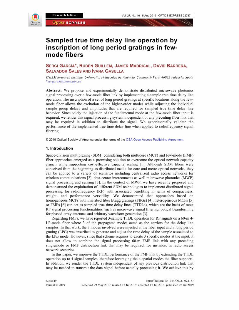
Sampled true time delay line operation by inscription of long period gratings in few-mode fibers SERGI GARCÍA*, RUBÉN GUILLEM, JAVIER MADRIGAL, DAVID BARRERA, SALVADOR SALES AND IVANA GASULLA ITEAM Research Institute, Universitat Politècnica de València, Camino de Vera, 46022 Valencia, Spain *[email protected]
Abstract: We propose and experimentally demonstrate distributed microwave photonics signal processing over a few-mode fiber link by implementing 4-sample true time delay line operation. The inscription of a set of long period gratings at specific locations along the few-mode fiber allows the excitation of the higher-order modes while adjusting the individual sample group delays and amplitudes that are required for sampled true time delay line behavior. Since solely the injection of the fundamental mode at the few-mode fiber input is required, we render this signal processing system independent of any preceding fiber link that may be required in addition to distribute the signal. We experimentally validate the performance of the implemented true time delay line when applied to radiofrequency signal filtering.
© 2019 Optical Society of America under the terms of the OSA Open Access Publishing Agreement
1. Introduction Space-division multiplexing (SDM) considering both multicore (MCF) and few-mode (FMF) fiber approaches emerged as a promising solution to overcome the optical network capacity crunch while supporting cost-effective capacity scaling [1]. Although SDM fibers were conceived from the beginning as distributed media for core and metro optical networks, they can be applied to a variety of scenarios including centralized radio access networks for wireless communications [2], data-center interconnects as well microwave photonics (MWP) signal processing and sensing [3]. In the context of MWP, we have recently proposed and demonstrated the exploitation of different SDM technologies to implement distributed signal processing for radiofrequency (RF) with associated benefiting in terms of compactness, weight, and performance versatility. We demonstrated that approaches based on homogeneous MCFs with inscribed fiber Bragg gratings (FBGs) [4], heterogeneous MCFs [5] or FMFs [6] can act as sampled true time delay lines (TTDLs), which are the basis of most RF signal processing functionalities, such as microwave signal filtering, optical beamforming for phased-array antennas and arbitrary waveform generation [3].
Regarding FMFs, we have reported 3-sample TTDL operation for RF signals on a 60-m 4-LP-mode fiber where 3 of the propagated modes acted as the carriers for the delay line samples. In that work, the 3 modes involved were injected at the fiber input and a long period grating (LPG) was inscribed to generate and adjust the time delay of the sample associated to the LP02 mode. However, since that scheme requires to excite 3 specific modes at the input, it does not allow to combine the signal processing 60-m FMF link with any preceding singlemode or FMF distribution link that may be required, for instance, in radio access network scenarios.
In this paper, we improve the TTDL performance of the FMF link by extending the TTDL operation up to 4 signal samples, therefore leveraging the 4 spatial modes the fiber supports. In addition, we render the TTDL system independent of any previous distribution link that may be needed to transmit the data signal before actually processing it. We achieve this by
Vol. 27, No. 16 | 5 Aug 2019 | OPTICS EXPRESS 22787
#368649 https://doi.org/10.1364/OE.27.022787 Journal © 2019 Received 29 May 2019; revised 17 Jul 2019; accepted 17 Jul 2019; published 25 Jul 2019

exciting only the fundamental mode while the remaining 3 higher-order modes are excited by 3 LPGs that are inscribed at proper positions along the FMF. These LPG-based mode converters excite the LP11, LP21 and LP02 modes with the pertinent sample amplitude and group delay required for TDDL operation. We experimentally validate the proposed device by successfully demonstrating RF signal filtering on different FMF link conditions.
2. Principle of operation We present a sampled TTDL built over a 4-LP-mode step-index fiber, which is provided by Prysmian. The fiber has a 15-μm-diameter core surrounded by a 125-μm-diameter cladding with a relative index contrast of 1.1%. The typical mode differential group delays per unit length (DGDs) relative to LP01 mode at a wavelength of 1550 nm are 4.4, 8.9 and 7.9 ps/m, respectively for LP11, LP21 and LP02 modes. The chromatic dispersions are 21, 26, 19 and 8 ps/nm/km respectively for LP01, LP11, LP21 and LP02 modes at 1550 nm. The light is injected/extracted into/from each mode by using mode multiplexers based on multi-plane light conversion that are provided by Cailabs. The average insertion losses and maximum modal crosstalk at 1550 nm for the pair comprising the mode multiplexer and demultiplexer when they are spliced together are 7.4 dB and below −20 dB, respectively.
Sampled TTDL operation for discrete-time signal processing requires a constant basic differential delay T between adjacent samples [3]. In our approach, the signals carried by the 4 LP modes at the FMF output correspond to the 4 TTDL samples. For each fiber mode n, the group delay per unit length τn can be expanded in first-order Taylor series around an anchor wavelength λ0 as:
( ) ( ) ( )0 0 0( ) ,n n nDτ λ τ λ λ λ λ= + − (1)
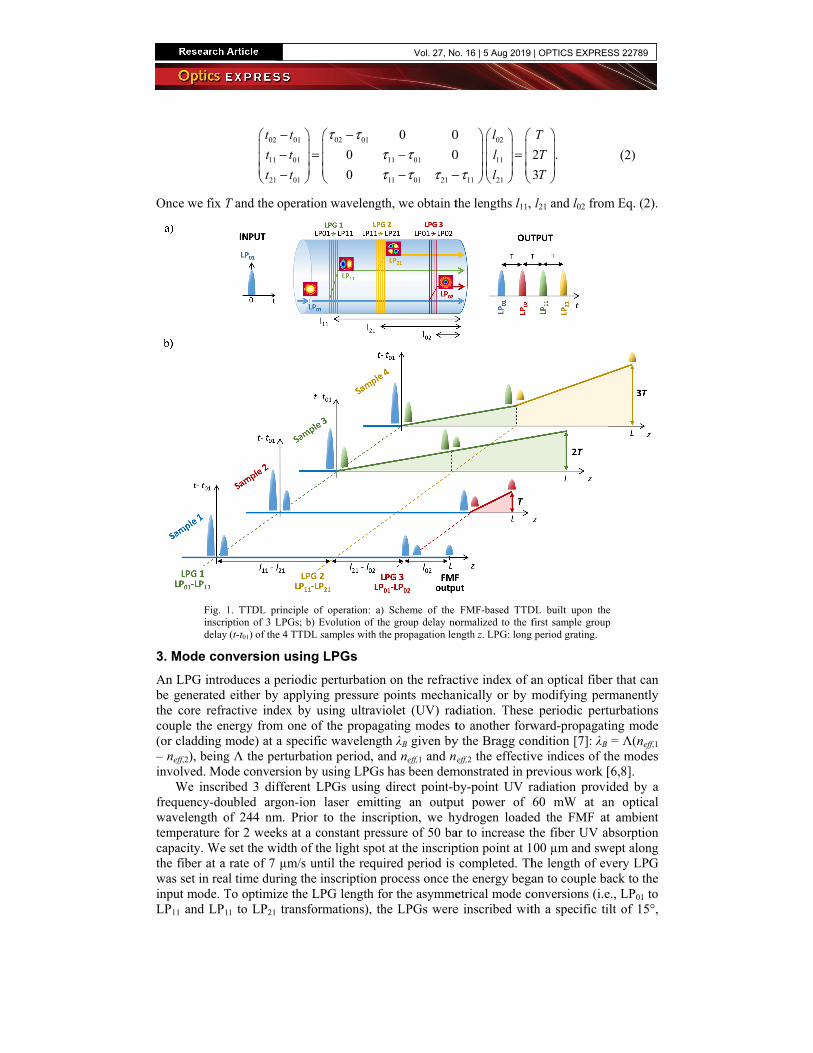
where n = {01, 11, 21, 02} and Dn is the chromatic dispersion parameter of n-th mode at λ0. Particularizing Eq. (1) with the current fiber mode parameters indicated above, we see that there is no solution for 4-sample TTDL operation in the C + L optical communications bands unless some time-delay engineering is implemented. To obtain 4 equally-spaced time samples, we propose to excite only the fundamental mode LP01 at the FMF input. Then, 3 mode converters based on LPGs are inscribed at certain positions along the fiber to couple the signal to the remaining modes while adjusting the amplitude and delay of the corresponding samples. The 3 LPGs convert: 1) LP01 to LP11 mode; 2) LP11 to LP21 mode; and 3) LP01 to LP02 mode. Each LPG must couple 50% of the power from the incoming to the generated mode to maintain the output samples with similar power level. Figure 1(a) depicts this concept.
Figure 1(b) shows the temporal evolution of the four samples referred to the first sample, t-t01, as a function of the propagation length z. At a given distance l11 from the fiber output, half the power of LP01 mode (blue) couples to LP11 mode (green) in the corresponding LPG mode converter. At the fiber output, the time delay of these samples is given by t01 = l11τ01 and t11 = l11τ11, respectively for sample 1 (output LP01 mode) and sample 3 (output LP11 mode), being τn the group delay per unit length of the n-th LP mode, n = {01, 11, 21, 02}, as given by Eq. (1). At a given distance l21 measured from the fiber output, a second LPG is inscribed to couple half the power of LP11 into LP21 mode (yellow), 0 < l21 < l11, so that the delay of sample 4 (output LP21 mode) is given by t21 = (l11 – l21)τ11 + l21τ21. In a similar way, at a distance l02 from the fiber output, 0 < l02 < l11, the last LPG is inserted to couple half the remaining LP01 power into LP02 mode (red), so that the delay of sample 2 (output LP02 mode) satisfies t02 = (l11 – l02)τ01 + l02τ02. For TTDL operation the time delay difference coming from modes LP11, LP21, LP02 related to LP01 mode must satisfy:
Vol. 27, No. 16 | 5 Aug 2019 | OPTICS EXPRESS 22788
Once we fix T
Fig. 1inscripdelay
3. Mode conAn LPG introbe generated the core refracouple the en(or cladding m– neff,2), beinginvolved. Mo
We inscrifrequency-douwavelength otemperature fcapacity. We the fiber at a was set in reainput mode. TLP11 and LP1
02 01
11 01
21 01
t t
t t
t t
− − −
T and the opera
1. TTDL principlption of 3 LPGs; (t-t01) of the 4 TTD
nversion usinoduces a periodeither by appl
active index bnergy from onemode) at a speg Λ the perturbde conversion ibed 3 differenubled argon-io
of 244 nm. Prifor 2 weeks at set the width orate of 7 µm/s
al time during tTo optimize the
1 to LP21 trans
02 01
0
0
τ τ− =
ation waveleng
e of operation: ab) Evolution of thDL samples with t
ng LPGs dic perturbationlying pressure y using ultrav
e of the propagcific waveleng
bation period, aby using LPGs
nt LPGs usingon laser emitior to the insca constant pre
of the light spos until the requhe inscription e LPG length fsformations), t
11 01
11 01 21
0 0
0τ ττ τ τ
−− −
gth, we obtain t
a) Scheme of the he group delay nothe propagation len
n on the refracpoints mechan
violet (UV) radgating modes tgth λB given byand neff,1 and ns has been dem direct point-b
tting an outpucription, we hyessure of 50 baot at the inscripuired period is process once thfor the asymmehe LPGs were
02
11
11 21
0
0 2
l
l
lτ
= −
the lengths l11,
FMF-based TTDormalized to the fngth z. LPG: long
ctive index of anically or by mdiation. Theseto another forwy the Bragg con
eff,2 the effectivmonstrated in pby-point UV rut power of ydrogen loade
ar to increase tption point at 1
completed. Thhe energy begaetrical mode coe inscribed wit
2 .
3
T
T
T
l21 and l02 from
DL built upon thefirst sample groupperiod grating.
an optical fibermodifying per
e periodic pertward-propagatindition [7]: λB ve indices of th
previous work [radiation provi60 mW at an
ed the FMF atthe fiber UV ab00 µm and swhe length of evan to couple baonversions (i.eth a specific ti
(2)
m Eq. (2).
e p
r that can rmanently turbations ing mode = Λ(neff,1
he modes [6,8]. ided by a n optical t ambient bsorption
wept along very LPG ack to the e., LP01 to ilt of 15°,
Vol. 27, No. 16 | 5 Aug 2019 | OPTICS EXPRESS 22789

measured perpendicularly to the fiber longitudinal axis. This tilt angle was determined experimentally and is given by a tradeoff between a bigger angle, which would produce a reduction on the visibility of the fringe pattern, and a lower angle, which would reduce the coupling efficiency and thus increase the coupling length. We must note that the power conversion efficiency of these asymmetrical modes strongly depends on the polarization state of the incoming optical field, so we must ensure operation at the optimal polarization state. Table 1 summarizes the main parameters describing the inscribed LPGs.
Table 1. Characteristics of the inscribed LPGs
LP01 to LP11 LP11 to LP21 LP01 to LP02
Period (µm) 685.0 545.2 262.5 Length (mm) 59.64 40.21 34.91 Tilt (deg) 15 15 0
After the inscription, heat annealing was done to ensure LPG stabilization by heating up
the fiber to 200 °C for 2 hours [9], accelerating the degradation effects derived from hydrogen diffusion and refractive index thermal decay, as reported in [6]. Figure 2 shows the optical spectrum in transmission of the three LPGs for all the LP modes once the LPGs reached a stable state after heat annealing. In the case of the asymmetrical LP modes, we represent the sum of both degenerate spatial modes, that is, LP11a + LP11b and LP21a + LP21b. The worst-case extinction ratio on the input mode is −10 dB (i.e., LP11 to LP21) at the optical wavelength λB, where almost all power is coupled to the mode excited, which is by far sufficient to allow the required 50% coupling efficiency for our TTDL scheme at a given wavelength near λB. The desired mode optical output powers can be adjusted by slightly tuning the operating wavelength to modify the mode conversion efficiency. At the wavelength of λ0 = 1558 nm, the mode conversion efficiencies are 0.58, 0.54 and 0.46 for each LPG (LP01 to LP02, LP01 to LP11 and LP11 to LP21, respectively), which allows to keep a similar amplitude level in all samples at the fiber output. Regarding crosstalk raised by the LPGs, we can see intermodal coupling values below −18 dB in all cases for the operating wavelength of 1558 nm, which are mainly due to the refractive index perturbation introduced by the LPG itself.
Fig. 2. Measured optical spectral response of each LPG in transmission for all the LP modes propagated through the FMF: a) LP01 to LP02 conversion; b) LP01 to LP11 conversion; c) LP11 to LP21 conversion.
4. Experimental validation: application to MWP signal filtering We have experimentally evaluated the performance of the implemented FMF-based TTDL in the context of MWP signal filtering. We set the operation wavelength to λ0 = 1558 nm and we looked for a sample differential delay of T = 100 ps, which translates into a RF filtering free spectral range (FSR) of 10 GHz. Prior to the LPG inscription, we characterized the DGDs of
a) b) c)
Vol. 27, No. 16 | 5 Aug 2019 | OPTICS EXPRESS 22790
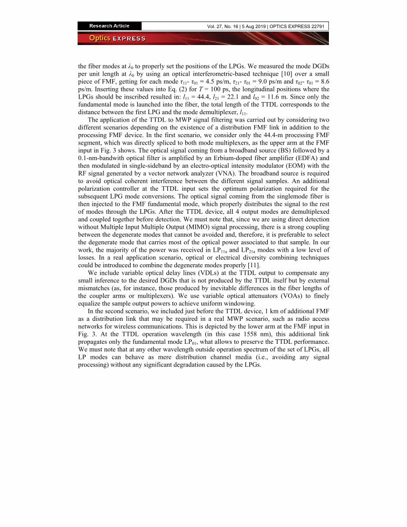
the fiber modes at λ0 to properly set the positions of the LPGs. We measured the mode DGDs per unit length at λ0 by using an optical interferometric-based technique [10] over a small piece of FMF, getting for each mode τ11- τ01 = 4.5 ps/m, τ21- τ01 = 9.0 ps/m and τ02- τ01 = 8.6 ps/m. Inserting these values into Eq. (2) for T = 100 ps, the longitudinal positions where the LPGs should be inscribed resulted in: l11 = 44.4, l21 = 22.1 and l02 = 11.6 m. Since only the fundamental mode is launched into the fiber, the total length of the TTDL corresponds to the distance between the first LPG and the mode demultiplexer, l11.
The application of the TTDL to MWP signal filtering was carried out by considering two different scenarios depending on the existence of a distribution FMF link in addition to the processing FMF device. In the first scenario, we consider only the 44.4-m processing FMF segment, which was directly spliced to both mode multiplexers, as the upper arm at the FMF input in Fig. 3 shows. The optical signal coming from a broadband source (BS) followed by a 0.1-nm-bandwith optical filter is amplified by an Erbium-doped fiber amplifier (EDFA) and then modulated in single-sideband by an electro-optical intensity modulator (EOM) with the RF signal generated by a vector network analyzer (VNA). The broadband source is required to avoid optical coherent interference between the different signal samples. An additional polarization controller at the TTDL input sets the optimum polarization required for the subsequent LPG mode conversions. The optical signal coming from the singlemode fiber is then injected to the FMF fundamental mode, which properly distributes the signal to the rest of modes through the LPGs. After the TTDL device, all 4 output modes are demultiplexed and coupled together before detection. We must note that, since we are using direct detection without Multiple Input Multiple Output (MIMO) signal processing, there is a strong coupling between the degenerate modes that cannot be avoided and, therefore, it is preferable to select the degenerate mode that carries most of the optical power associated to that sample. In our work, the majority of the power was received in LP11a and LP21a modes with a low level of losses. In a real application scenario, optical or electrical diversity combining techniques could be introduced to combine the degenerate modes properly [11].
We include variable optical delay lines (VDLs) at the TTDL output to compensate any small inference to the desired DGDs that is not produced by the TTDL itself but by external mismatches (as, for instance, those produced by inevitable differences in the fiber lengths of the coupler arms or multiplexers). We use variable optical attenuators (VOAs) to finely equalize the sample output powers to achieve uniform windowing.
In the second scenario, we included just before the TTDL device, 1 km of additional FMF as a distribution link that may be required in a real MWP scenario, such as radio access networks for wireless communications. This is depicted by the lower arm at the FMF input in Fig. 3. At the TTDL operation wavelength (in this case 1558 nm), this additional link propagates only the fundamental mode LP01, what allows to preserve the TTDL performance. We must note that at any other wavelength outside operation spectrum of the set of LPGs, all LP modes can behave as mere distribution channel media (i.e., avoiding any signal processing) without any significant degradation caused by the LPGs.
Vol. 27, No. 16 | 5 Aug 2019 | OPTICS EXPRESS 22791
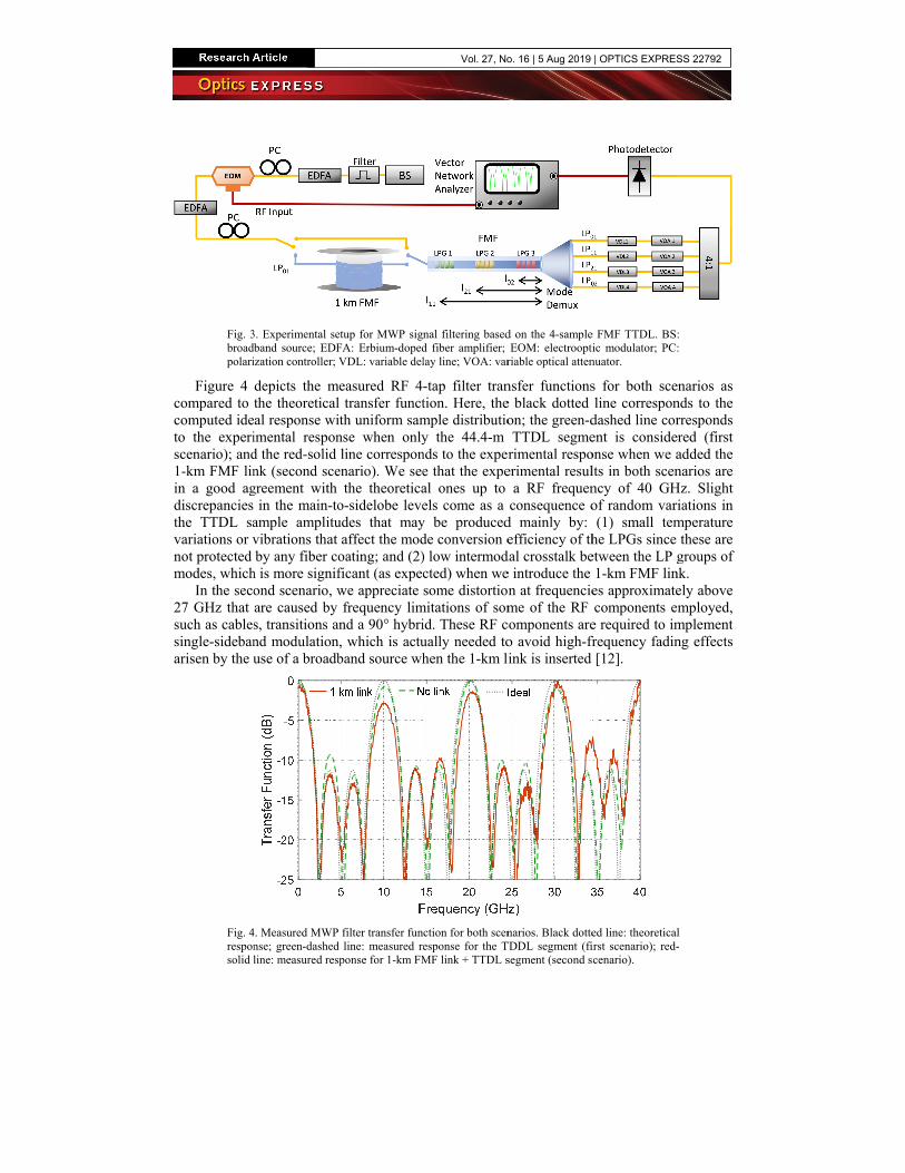
Fig. 3broadpolari
Figure 4 compared to computed ideto the experiscenario); and1-km FMF linin a good agdiscrepancies the TTDL savariations or vnot protected modes, which
In the seco27 GHz that such as cablessingle-sidebanarisen by the u
Fig. 4responsolid l
3. Experimental seband source; EDFization controller;
depicts the mthe theoreticalal response wiimental respond the red-solid nk (second scegreement with
in the main-toample amplituvibrations that by any fiber co
h is more signifond scenario, ware caused by s, transitions and modulationuse of a broadb
4. Measured MWPnse; green-dashedline: measured res
etup for MWP signFA: Erbium-dopedVDL: variable del
measured RF 4l transfer functith uniform samnse when onlyline correspon
enario). We seethe theoretica
o-sidelobe leveudes that mayaffect the mod
oating; and (2)ficant (as expecwe appreciate frequency lim
nd a 90° hybri, which is actuband source wh
filter transfer fund line: measured reponse for 1-km FM
nal filtering basedd fiber amplifier; lay line; VOA: var
-tap filter trantion. Here, themple distributioy the 44.4-m
nds to the expere that the expeal ones up to els come as a
y be producedde conversion e) low intermodcted) when wesome distortion
mitations of somid. These RF cually needed tohen the 1-km l
ction for both scenesponse for the TMF link + TTDL s
d on the 4-sampleEOM: electroopti
riable optical atten
nsfer functionse black dotted on; the green-dTTDL segme
rimental respoerimental resul
a RF frequenconsequence o
d mainly by: efficiency of th
dal crosstalk bee introduce the n at frequencieme of the RF
components areo avoid high-frink is inserted
narios. Black dotteTDDL segment (fisegment (second s
e FMF TTDL. BSic modulator; PC:
nuator.
s for both sceline correspon
dashed line corent is consideonse when we alts in both scenncy of 40 GHof random var(1) small tem
he LPGs since etween the LP g1-km FMF lines approximatecomponents e
e required to imfrequency fadin
[12].
ed line: theoreticalirst scenario); red-cenario).
: :
enarios as nds to the rresponds
ered (first added the narios are
Hz. Slight iations in
mperature these are
groups of nk. ely above mployed,
mplement ng effects
l -
Vol. 27, No. 16 | 5 Aug 2019 | OPTICS EXPRESS 22792

5. Conclusions Within the framework of fiber-distributed MWP signal processing, we have proposed and experimentally demonstrated an FMF-based sampled TTDL for RF frequencies around 10 GHz. Three LPGs conveniently inscribed along the 44.4-m FMF link provide 2 fundamental functionalities: (1) in-fiber excitement of the 3 higher-order modes and (2) tailoring of both amplitude and group delay of the signal samples as to accomplish TTDL operation. Among the variety of discrete-time signal processing applications that can be built by means of this TTDL, we demonstrated here a 4-tap periodic RF filter with an FSR of 10 GHz. We demonstrated as well that the 44.4-m processing device can coexist in short-reach radio-over-fiber scenarios, such as a radio access networks, where an additional distribution link may be required, showing no significant degradation over the TTDL performance.
We would like to point out that the rationale beyond the use of a single FMF instead of N parallel SMFs for N-sample TTDL operation lies in the reduction of size and weight by a factor N. This is an important feature for network deployment in next-generation fiber-wireless communications systems where, for instance, optical beamforming networks for phased array antennas will cope with a high number of radiating elements featuring smaller sizes. Although we have demonstrated here a 4-sample TTDL, the gain in compactness will grow more significant if we scale up the number of samples.
Funding European Research Council (ERC) (Consolidator Grant 724663); Spanish MINECO (TEC2014-60378-C2-1-R and TEC2016-80150-R projects, BES-2015-073359 scholarship for S. García, IJCI-2017-32476 fellowship for D. Barrera, Ramon y Cajal fellowship RYC-2014-16247 for I. Gasulla); Universitat Politècnica de València (PAID-01-18 scholarship for J. Madrigal).
References <jrn>1. D. J. Richardson, J. M. Fini, and L. E. Nelson, “Space-division multiplexing in optical fibers,” Nat.
Photonics 7(5), 354–362 (2013).</jrn> <jrn>2. J. M. Galve, I. Gasulla, S. Sales, and J. Capmany, “Reconfigurable radio access networks using multicore
fibers,” IEEE J. Quantum Electron. 52(1), 1–7 (2016).</jrn> <jrn>3. J. Capmany, J. Mora, I. Gasulla, J. Sancho, J. Lloret, and S. Sales, “Microwave photonic signal
procesing,” J. Lightwave Technol. 31(4), 571–586 (2013).</jrn> <jrn>4. I. Gasulla, D. Barrera, J. Hervás, and S. Sales, “Spatial Division Multiplexed Microwave Signal
processing by selective grating inscription in homogeneous multicore fibers,” Sci. Rep. 7(41727), 41727 (2017).</jrn>
<jrn>5. S. García and I. Gasulla, “Dispersion-engineered multicore fibers for distributed radiofrequency signal processing,” Opt. Express 24(18), 20641–20654 (2016).</jrn>
<jrn>6. R. Guillem, S. García, J. Madrigal, D. Barrera, and I. Gasulla, “Few-mode fiber true time delay lines for distributed radiofrequency signal processing,” Opt. Express 26(20), 25761–25768 (2018).</jrn>
<jrn>7. V. Bhatia and A. M. Vengsarkar, “Optical fiber long-period grating sensors,” Opt. Lett. 21(9), 692–694 (1996).</jrn>
<jrn>8. Y. Zhao, Y. Liu, L. Zhang, C. Zhang, J. Wen, and T. Wang, “Mode converter based on the long-period fiber gratings written in the two-mode fiber,” Opt. Express 24(6), 6186–6195 (2016).</jrn>
<jrn>9. G. Bai, T. Hwa, H. Siu, L. Shun, and D. Xiao, “Growth of long-period gratings in H2-loaded fiber after 193-nm UV inscription,” IEEE Photonics Technol. Lett. 12(6), 642–644 (2000).</jrn>
<jrn>10. C. Dorrer, N. Belabas, J. Likforman, and M. Joffre, “Spectral resolution and sampling issues in Fourier-transform spectral interferometry,” J. Opt. Soc. Am. B 17(10), 1795–1802 (2000).</jrn>
<jrn>11. I. Gasulla and J. M. Kahn, “Performance of direct-detection mode-group-division multiplexing using fussed fiber couplers,” IEEE J. Lightw. Technol. 33(9), 1748–1760 (2015).</jrn>
<jrn>12. F. Grassi, J. Mora, B. Ortega, and J. Capmany, “Subcarrier multiplexing tolerant dispersion transmission system employing optical broadband sources,” Opt. Express 17(6), 4740–4751 (2009).</jrn>
Vol. 27, No. 16 | 5 Aug 2019 | OPTICS EXPRESS 22793