Embed Size (px)
Citation preview
SAMPLING AND ANALYSIS FIELD SAMPLING PLAN FOR SITE INVESTIGATIONS AND RCRA FACILITY INVESTIGATIONS AT THE FORT CHAFFEE FACILITY, FORT CHAFFEE, ARKANSAS
by Phillip D. Hays and Gregory P. Stanton
U.S. GEOLOGICAL SURVEY Open-File Report 96-118
Prepared in cooperation with the
U.S. ARMY, FORT CHAFFEE ENVIRONMENTAL BRANCH
Little Rock, Arkansas 1996
U.S. DEPARTMENT OF THE INTERIOR
BRUCE BABBITT, Secretary
U.S. GEOLOGICAL SURVEY GORDON P. EATON, Director
For additional information Copies of this report can be write to: purchased from:
District Chief U.S. Geological Survey U.S. Geological Survey Earth Science Information Center 401 Hardin Road Open-File Reports Section Little Rock, AR 72211 Box 25286, MS 517
Federal Center Denver, CO 80225
CONTENTS
Page
Abstract.................................................................... 1Introduction................................................................ 11.0 Methods and Procedures.................................................. 2
1.1 Study Point Preparation............................................. 2
1.1.1 Borehole Construction, Lithologic Sampling, and Logging ....... 21.1.2 Monitor Well Construction and Development .................. 21.1.3 Piezometer Installation ...................................... 31.1.4 Large Equipment Decontamination Procedure.................. 31.1.5 Contaminated Media........................................ 41.1.6 Surveying ................................................. 4
1.2 Environmental Sampling............................................ 41.2.1 Soil-Gas Surveys............................................ 41.2.2 Ground-Water Sampling..................................... 51.2.3 Ground-Water Sampling Pump Decontamination .............. 111.2.4 Enzyme-Linked Immunosorbent Assay....................... 121.2.5 Soil and Sediment Sample Collection......................... 131.2.6 Water-level measurements .................................. 131.2.7 Wipe Sampling............................................ 141.2.8 Rinsate Sampling .......................................... 15
1.3 Sample Identification/Designation .................................. 151.4 Sampling Handling................................................ 181.5 Sample Custody .................................................. 19
1.6 Aquifer Testing ................................................... 20
1.6.1 Equipment................................................ 201.6.2 Slug Test Procedures ....................................... 201.6.3 Pumping Test Procedure.................................... 211.6.4 Data Management and Analysis ............................. 21
2.0 Field Measurements ..................................................... 212.1 Parameters ....................................................... 21
2.2 Equipment Calibration ............................................ 212.3 Equipment Maintenance ........................................... 23
3.0 Field Quality-Control Samples ............................................ 233.1 Trip Blanks ....................................................... 253.2 Equipment Blanks................................................. 25
CONTENTS (Continued)
Page
3.3 Ambient Condition Blanks ......................................... 253.4 Field Duplicates/Replicates ........................................ 253.5 Matrix Spikes/Matrix Spike Duplicates .............................. 26
4.0 Control Parameters...................................................... 265.0 Record Keeping and Data Management.................................... 286.0 Site Management........................................................ 29
TABLES
Table 1. QA/QC samples ....................................................162. Location type abbreviations...........................................163. Matrix designations..................................................174. Quality-control summary.............................................235. Quality analysis/quality control rationale and means.....................24
IV
SAMPLING AND ANALYSIS FIELD SAMPLING PLAN FOR SITEINVESTIGATIONS AND RCRA FACILITY INVESTIGATIONS
AT THE FORT CHAFFEE FACILITY, FORT CHAFFEE, ARKANSASBy Phillip D. Hays and Gregory P. Stanton
ABSTRACT
The Field Sampling Plan component of the Fort Chaffee Sampling and Analysis Quality Assurance Plan is designed to describe procedures that will be used during sample collection and analysis for environmental studies to be undertaken by the U.S. Geological Survey at the Fort Chaffee facility. The Field Sampling Plan provides personnel with a technical reference for guid ing data collection in the field, and in combination with the Quality Assurance Project Plan, will ensure that the data generated as a result of the Resource Conservation and Recovery Act facility investigations and site investigations are of sufficient quality and quantity to support investigation objectives.
INTRODUCTION
The Field Sampling Plan (FSP) component of the Fort Chaffee Sampling and Analysis Quality Assurance Plan is designed to describe procedures that will be used during sample collec tion and analysis for environmental studies to be undertaken by the U.S. Geological Survey (USGS) at the Fort Chaffee facility. The FSP provides personnel with a technical reference for guiding data collection in the field, and in combination with the Quality Assurance Project F'an (QUAPP), will ensure that the data generated as a result of the Resource Conservation and Recov ery Act (RCRA) facility investigations (RFI) and site investigations are of sufficient quality and quantity to support investigation objectives.
The FSP describes methodologies for sampling data-collection activities required to address environmental investigation needs at the Fort Chaffee facility, including:
Study point preparation,
Environmental sampling protocols,
Quality control sampling,
Decontamination protocols, and
Field screening techniques.
Associated with activity descriptions is a discussion of activity objectives and rationale; required equipment; location; and designation, handling, and analysis of activity products.
The FSP must meet the challenge of changing regulatory requirements, technical improve ments, and unforeseen circumstances to be encountered at the varied sites that must be addressed, and therefore, improvements must be expected to be incorporated over time to meet changing requirements and take advantage of advancing technologies and approaches.
1.0 Methods and Procedures 1.1 Study Point Preparation
1.1.1 Borehole construction, lithologic sampling, and logging Rorings will be installed with a suitable drilling unit. Auger flights and cutting head will be decontaminated between each boring by steam cleaning, followed by the standard large-equipment decontamination procedure described in section 1.1.4. During drilling at sites determined by the field team leader to have the potential for holding free product (volatiles or other hazardous materials) in the water-table aqui fer, cuttings will be monitored with an organic-vapor analyzer to screen for possible contamina tion. A descriptive log of the soil cuttings will be completed for each borehole. Lithologic descriptions will be made at 2-ft intervals unless major changes dictate more frequent description. The descriptions will follow a modified ASTM method D2488 format. The borehole log will con tain the information listed on the borehole log form and will include but is not restricted to:
1. spud start date and time,
2. drilling period times and progress,
3. well location and identifying number,
4. altitude of land-surface datum derived from topographic contour map (surveys will be con ducted after construction),
5. lithologic/soil log,
6. drill crew members,
7. positive organic vapor analyzer (OVA) readings if OVA is used,
8. borehole total depth,
9. drilling method, and
10. sampling methods.
Borehole locations will be flagged, surveyed, and recorded on the site map. Abandoned soil bor ings will be pressure cemented to surface using a cement/bentonite slurry.
Any drill cuttings or developmental water suspected of being contaminated (by screening with an OVA) will be containerized into 55-gallon drums or 1-cubic yard hazardous waste boxes. Composite samples from the drums will be sent to the laboratory for chemical analyses of the parameters of interest as determined for the site. Drums containing contaminated materials w : ll be sent to the DRMO facility at Fort Chaffee for proper disposal.
1.12 Monitor well construction and development The shallow monitor wells will be constructed of either 2- or 4-inch diameter (internal diameter (i.d.)) schedule 40 or 80 polyvinyl chloride (PVC) pipe. From 3 to 20 ft of the upper part of the surficial aquifer will be screened. Screer slot sizes selected and installed will be based on the particle-size distribution of soil samples of the surficial aquifer. All screen and casing will be threaded and flush-jointed type. Screen will extend approximately 2 ft above initially observed water levels in order to allow for fluctuation of water levels, unless the water level is within 2 ft of the surface. A clean filter-pack sand will be emplaced around the screen, extending approximately 2 ft above the screen. A 2- to 5-ft bentonite seal will be emplaced above the sand pack, and the remainder of the borehole annular space will be filled either with bentonite or a bentonite/Portland-cement slurry. A minimum of 24 hours will be allowed for hydration of bentonite pellets (if this is the form of bentonite used) and setting of
any grout used prior to initiating well development. The wells will be developed by removing a minimum of three well-casing volumes by teflon bailer or noninterfering pump. The purpose of development is to produce and remove mobile sediment and filter pack near the borehole so that representative ground-water samples can be obtained.
Well locations will be determined by examining available data. Wells will be positioned such that the vertical and horizontal extent of contamination can be defined; at least one upgradi- ent well will be installed at each site. Cluster wells will be placed in areas where there is potential for a dense nonaqueous phase liquid (DNAPL). Cluster wells will be placed so that a three- dimension definition of hydrogeology and site conditions can be defined. Well locations will be specified in each individual site work plan.
1.13 Piezometer installation~Ca.sa.grande or open-tube piezometers may be installed using the drive point method or by auger drilling. A drive point consists of a well point (typically steel) that is attached to steel casing of 1.25 to 2 inches in diameter. The well point and casing are driven into the ground to the desired depth. Piezometers completed by auger drilling will be constructed of small-diameter, PVC pipe and screen (approximately 1 inch internal diameter (i.d.)); these pie zometers will be completed in a manner similar to the monitoring well completion.
1.1.4 Large equipment decontamination /?rocedwre--Decontamination of drilling and well-instal lation equipment, e.g. casing, screen, drill bits, auger flights, drill rods, drive points, split-spoon and other samplers, will be conducted at a specially designated site at the Fort Chaffee wash rack facility. The decontamination procedure will be as follows:
1. Steam cleaning or high pressure hot water washing may be used to preclean, remove tena cious materials, and clean difficult to access internal areas (e.g. casing or auger flight interi ors) as needed. The steam cleaning/high pressure wash unit will be capable of generating a pressure of 800 pounds per square inch (psi) and water temperatures of 200 °F.
2. Potable tap water and lab-grade detergent will be used to scrub equipment with a brush, fol lowed by a tap-water rinse.
3. The equipment will be rinsed with deionized water. *Note-Decontamination liquids subse quent to the tap-water rinse must be administered with noninterfering/noncontaminating containers. These containers will be made of glass, Teflon, or stainless steel.
4. The deionized water rinse will be followed by a solvent rinse (pesticide-grade or reagent- grade methanol or isopropanol).
5. If the equipment is to be stored overnight or longer or may be exposed to extraneous con tamination, aluminum foil or plastic may be used to wrap and isolate the equipment. If plastic is used, the equipment must be thoroughly air dried prior to wrapping and storage.
In cases where equipment is painted, extensively rusted, or coated with difficult to remove materials, sandblasting may be necessary to ensure adequate decontamination.
Equipment exposed to contaminated media will be cleaned over a plastic lining that drains to a lined catchment. Minimal volumes of water and solvents will be applied, and all cleaning flu ids will be collected and containerized for disposal. Decontamination of equipment potentially contaminated with hazardous materials (as determined at the Solid Waste Management Unit (SWMU) by OVA screening, visually, or judgementally in areas where the likelihood of encoun tering contamination is great) will be conducted over a plastic liner emplaced so that rinsate is
collected in a sump trench next to the wash rack pad. If contamination of equipment during post operation cleanup is suspected or indicated by screening techniques at the site, rinsate will tr, pumped from the sump, sampled, analyzed (enzyme-linked immunosorbent assay (ELISA) will be the preferred technique for DDT and most constituents), and disposed of in a compliant fash ion if hazardous constituents are present in rinsate at concentrations above action levels outlined in CFR 40 Proposed Subpart S. Otherwise, rinsate will be routed to the sanitary sewer system.
7.7.5 Contaminated media-M OVA concentrations monitored are more than 5 parts per million (ppm) above background levels, or if evidence exists of contaminated material (visual, GC, or other indications) then drill cuttings, fluids, and materials adhering to equipment will be assumed to be contaminated. The materials will be analyzed by a more specific screening technique, such as ELIS A, or other applicable technique and will be containerized and disposed of as hazardous waste.
7.7.6 Surveying USGS personnel will spot map locations on topographic maps and survey the elevations of newly constructed monitor wells, soil borings, and other sampling points as needed. Surveyed locations will be recorded on project maps.
1.2 Environmental Sampling
7.2.7 Soil-gas surveys--Using a portable gas chromatograph and organic vapor analyzer, soil-gas (vadose zone gas) surveys will be conducted where needed to accrue real-time data on the emis sion of volatile organic compounds. While results of this type of testing are qualitative in nature, the data will aid definition of subsurface contamination and enable adjustment of drilling and sampling plans.
A Photovac 10S50 portable gas chromatograph (GC) equipped with a capillary column will be used to analyze soil-gas samples. The GC will be calibrated according to manufacturers sieci- fications for retention times using applicable analytical standards; potentially useful standards include, but are not limited to, benzene, toluene, xylene, and dichlorobenzene. Hydrocarbon-free air will be used as the carrier gas. The soil-gas sampling method to be used is as follows:
1. Syringes and other sampling equipment will be checked for contamination by drawing atmospheric air through the system and checking the results obtained against air blanks analyzed during the same period.
2. A small-diameter hole (approximately 0.75-inch diameter) will be driven into the ground to depths of approximately 0.2 to 2 ft using a plunger bar or other impact driver at each sam pling location. The developed sampling location grid will focus the majority of sampling points outside of the obviously contaminated area in order to best define the extent of con tamination.
3. A previously cleaned stainless-steel probe will be inserted into the hole; the hole will be sealed at the surface to isolate the soil gas from atmospheric gases.
4. A Foxborough flame-ionization detector/organic vapor analyzer (OVA) will be used to measure the total concentration of volatile organic compound (VOC) (i.e. total ionizaUe species concentration) in the soil gas and determine proper sample volumes to be used for GC analysis.

5. One to 5 liters of gas will be withdrawn from the hole using a low-volume pump. TH flow will be monitored to verify that the probe is not restricted and that the porosity of the soil is sufficient to yield a sample.
6. A soil-gas sample will be drawn from the evacuation line using a glass syringe; the sam pling point will be on the low pressure side of the vacuum pump and pressure meter to avoid contamination by the pump.
7. The soil-gas sample will be injected into the GC and analyzed. The GC column will be purged with hydrocarbon-free air between each sample run. System blanks will be run intervening each sample run to check for system contamination.
8. Standards will be run at the beginning and end of each sampling day and at any time during sampling when the analyst determines that the instrument needs to be field standard1 zed.
7.2.2 Ground-water sampling Ground-water samples will be collected from wells that have been fully developed. Wells will be allowed to stabilize a minimum of 10 days after development before sampling is conducted. Wells will be purged of one to five well volumes (depending upon the recovery time wells that do not recover overnight will be purged of only one well volume) prior to sampling. Temperature, pH, and specific conductance will be monitored and recorded at 10-minute intervals during purging; if these parameters have not stabilized within a range of +1.0 °C for temperature, +0.5 units for pH, and +15 microsiemens for conductivity for each 10- minute monitoring period, then a minimum of one additional well volume will be purged prior to initiating sampling. Low-yield wells that do not exhibit stable field parameters after purge and recovery may be sampled after purging two well volumes.
Purging and sample collection will be conducted using a noninterfering (stainless steel and teflon construction for surfaces exposed to the sample), positive-displacement pump or bailer.
Inorganic constituent sampling will follow USGS low-level sampling protocols designed and tested to afford reliable data at microgram/liter concentration levels. Organic sampling will follow stringent sampling procedures similar to those applied for inorganic sampling to ensure good data quality; the primary difference from inorganic sampling procedures being avoidance of a different set of contaminant interferences by way of organic-directed decontamination, sample isolation and collection, and sample handling. Equipment decontamination and field sampling methods are the critical components of sampling programs designed to provide reliable data at low concentration levels. The protocol for sampling and equipment decontamination to be fol lowed for this project is described below as a sequence of three procedures. Organic decontamina tion protocols for equipment used for organic sampling will follow Procedures 1 and 3 except that, in the final step, a methanol rinse and an organic-free water rinse step will be performed instead of an inorganic-free water rinse.
Equipment that will be in contact with the sample will be subjected to Procedure 1, a univer sal cleaning procedure intended to remove contaminants related to new or stored equipment. Pre- cleaned equipment, such as capsule filters, will not be subjected to additional cleaning, but will be used directly from unopened packaging.
Procedure 2 sets forth a sample processing and preservation method design to avoid various contamination vectors during sample filtration, bottling, and preservation.
Procedure 3 describes a field cleaning regimen designed to apply between sites in the field and ensure avoidance of any cross contamination.
PROCEDURE 1: OFFICE PREPARATIONS AND CLEANING OF EQUIPMENT
RATIONALE
New or previously used and stored equipment (stored without adequate cleaning or pacVag- ing) is likely to contain, or have adhering to it, a wide variety of potential contaminants. The pur pose of the universal cleaning procedure is to ensure that these potential contaminants are removed prior to using the equipment. This procedure is applicable for equipment that will b a, used to obtain material for subsequent analysis and will have direct contact with sampled media. This is a three-step procedure using detergent, tap water, and deionized water (DIW), as well as dilute acid, methanol, organic-free water, and inorganic-free water; the latter agents use depends upon the equipment to be applied and the target analytes. The detergent is basic, and is used in conjunction with brushes for external surfaces to remove any adhering material. Most of the detergent residue will be removed with tap water. Any remaining films and detergent residues will be removed with acid. Acid residues will be removed with deionized water. Any remaining organic compound residues will be more efficiently removed by the methanol rinse applied for equipment used for organic sampling. Low levels of any compounds left on the equipment (<?* in fluid residue) will be removed in the final organic- (for organic sampling) or inorganic-free (for inorganic sampling) rinse. Procedure 1 is not to be applied for sampling pumps and hose; a proce dure specific to pump decontamination is detailed in section 1.2.3.
REQUISITE SUPPLIES
1. DIW (Office of Water Quality Technical Memorandum 92.01),
2. Concentrated, trace-element free HC1 (Baker Instra-Analyzed (37 percent), USGS Ocala lab inorganic-free, or equivalent). Aliquots must be diluted with DIW to 5 percent (50 mL/ L, V/V) and stored in a noncontaminating container,
3. Reagent-grade methanol,
4. Organic-free water,
5. Inorganic-free water,
6. Assorted safety-labeled wash bottles for DIW and dilute acid,
7. Liquid detergent (Liquinox) that does not contain phosphates,
8. Disposable, nonpowdered vinyl gloves,
9. Noncontaminating, nonmetallic, clear/uncolored polypropylene/high-density polyethylene basins (minimum of four),
10. Various noncontaminating (nonmetallic, uncolored) brushes,
11. Assorted scalable plastic bags for storage and transport after cleaning.
Note: All cleaning fluid containers should be stored in sealed plastic bags.
PROCEDURE
1. Before cleaning the equipment, clean the four basins; label each basin and wash bottler with a waterproof marker. Each item must be cleaned with: (a) detergent, (b) tap water, (c) dilute acid, and (d) DIW. Read through this procedure and follow the appropriate steps for the items, as if they were part of the sampling/processing equipment, before beginning to clean the equipment itself.
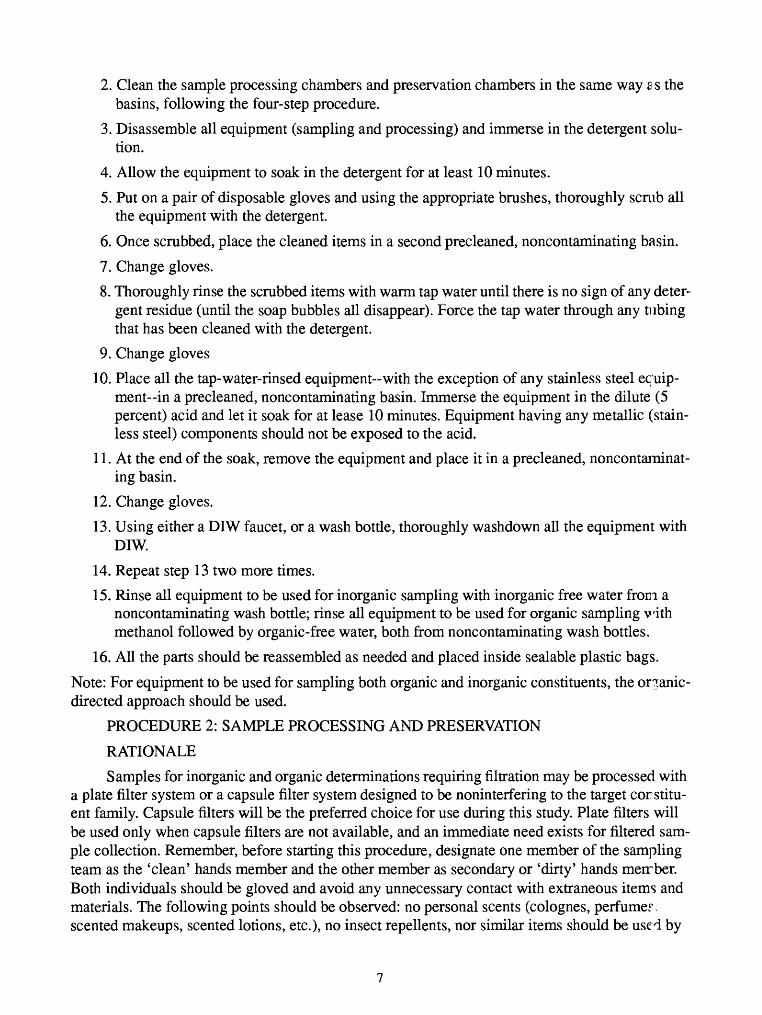
2. Clean the sample processing chambers and preservation chambers in the same way 2 s the basins, following the four-step procedure.
3. Disassemble all equipment (sampling and processing) and immerse in the detergent solu tion.
4. Allow the equipment to soak in the detergent for at least 10 minutes.
5. Put on a pair of disposable gloves and using the appropriate brushes, thoroughly scrub all the equipment with the detergent.
6. Once scrubbed, place the cleaned items in a second precleaned, noncontaminating basin.
7. Change gloves.
8. Thoroughly rinse the scrubbed items with warm tap water until there is no sign of any deter gent residue (until the soap bubbles all disappear). Force the tap water through any tubing that has been cleaned with the detergent.
9. Change gloves
10. Place all the tap-water-rinsed equipment-with the exception of any stainless steel equip ment in a precleaned, noncontaminating basin. Immerse the equipment in the dilute (5 percent) acid and let it soak for at lease 10 minutes. Equipment having any metallic (stain less steel) components should not be exposed to the acid.
11. At the end of the soak, remove the equipment and place it in a precleaned, noncontaminat ing basin.
12. Change gloves.
13. Using either a DIW faucet, or a wash bottle, thoroughly washdown all the equipment with DIW.
14. Repeat step 13 two more times.
15. Rinse all equipment to be used for inorganic sampling with inorganic free water from a noncontaminating wash bottle; rinse all equipment to be used for organic sampling with methanol followed by organic-free water, both from noncontaminating wash bottles.
16. All the parts should be reassembled as needed and placed inside scalable plastic bags.
Note: For equipment to be used for sampling both organic and inorganic constituents, the organic- directed approach should be used.
PROCEDURE 2: SAMPLE PROCESSING AND PRESERVATION
RATIONALE
Samples for inorganic and organic determinations requiring filtration may be processed with a plate filter system or a capsule filter system designed to be noninterfering to the target corstitu- ent family. Capsule filters will be the preferred choice for use during this study. Plate filters will be used only when capsule filters are not available, and an immediate need exists for filtered sam ple collection. Remember, before starting this procedure, designate one member of the sampling team as the 'clean' hands member and the other member as secondary or 'dirty' hands merrber. Both individuals should be gloved and avoid any unnecessary contact with extraneous items and materials. The following points should be observed: no personal scents (colognes, perfumer, scented makeups, scented lotions, etc.), no insect repellents, nor similar items should be used by
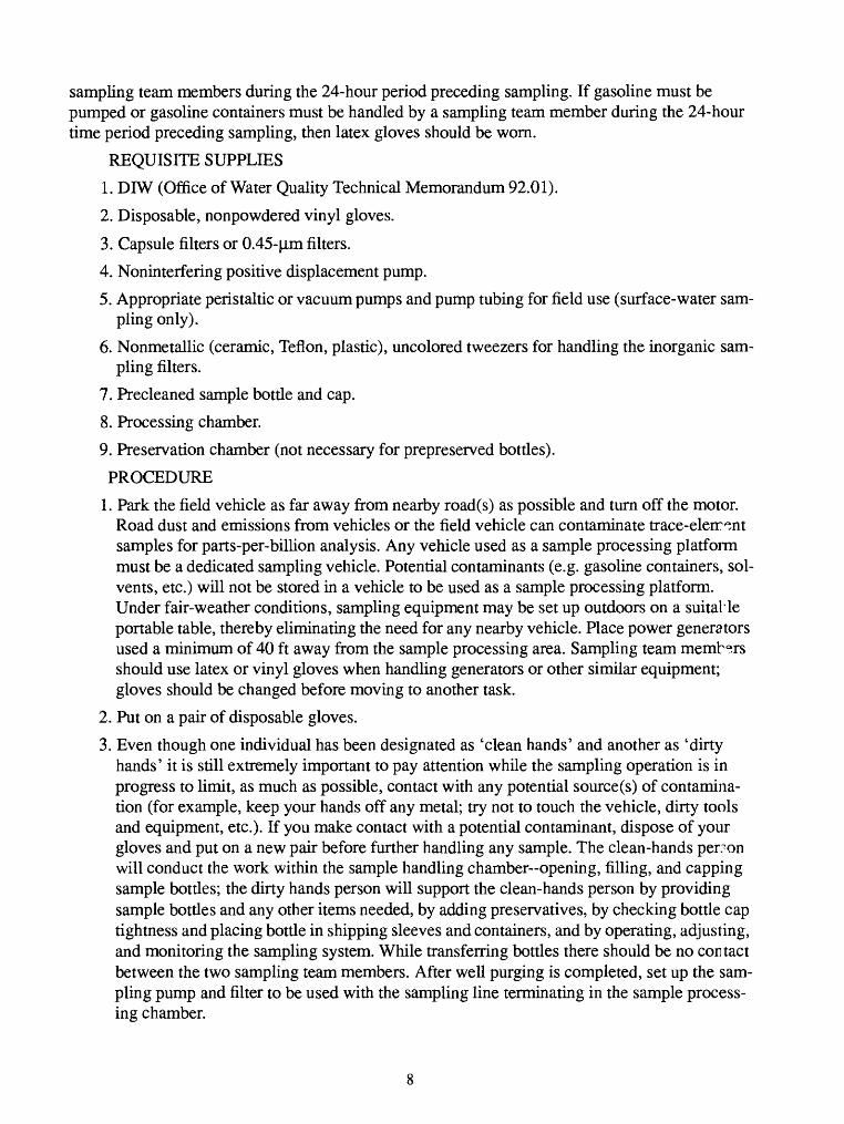
sampling team members during the 24-hour period preceding sampling. If gasoline must be pumped or gasoline containers must be handled by a sampling team member during the 24-hour time period preceding sampling, then latex gloves should be worn.
REQUISITE SUPPLIES
1. DIW (Office of Water Quality Technical Memorandum 92.01).
2. Disposable, nonpowdered vinyl gloves.
3. Capsule filters or 0.45-|J.m filters.
4. Noninterfering positive displacement pump.
5. Appropriate peristaltic or vacuum pumps and pump tubing for field use (surface-water sam pling only).
6. Nonmetallic (ceramic, Teflon, plastic), uncolored tweezers for handling the inorganic sam pling filters.
7. Precleaned sample bottle and cap.
8. Processing chamber.
9. Preservation chamber (not necessary for prepreserved bottles).
PROCEDURE
1. Park the field vehicle as far away from nearby road(s) as possible and turn off the motor. Road dust and emissions from vehicles or the field vehicle can contaminate trace-elerr^nt samples for parts-per-billion analysis. Any vehicle used as a sample processing platform must be a dedicated sampling vehicle. Potential contaminants (e.g. gasoline containers, sol vents, etc.) will not be stored in a vehicle to be used as a sample processing platform. Under fair-weather conditions, sampling equipment may be set up outdoors on a suitaHe portable table, thereby eliminating the need for any nearby vehicle. Place power generators used a minimum of 40 ft away from the sample processing area. Sampling team members should use latex or vinyl gloves when handling generators or other similar equipment; gloves should be changed before moving to another task.
2. Put on a pair of disposable gloves.
3. Even though one individual has been designated as 'clean hands' and another as 'dirty hands' it is still extremely important to pay attention while the sampling operation is in progress to limit, as much as possible, contact with any potential source(s) of contamina tion (for example, keep your hands off any metal; try not to touch the vehicle, dirty tools and equipment, etc.). If you make contact with a potential contaminant, dispose of your gloves and put on a new pair before further handling any sample. The clean-hands person will conduct the work within the sample handling chamber opening, filling, and capping sample bottles; the dirty hands person will support the clean-hands person by providing sample bottles and any other items needed, by adding preservatives, by checking bottle cap tightness and placing bottle in shipping sleeves and containers, and by operating, adjusting, and monitoring the sampling system. While transferring bottles there should be no contact between the two sampling team members. After well purging is completed, set up the sam pling pump and filter to be used with the sampling line terminating in the sample process ing chamber.
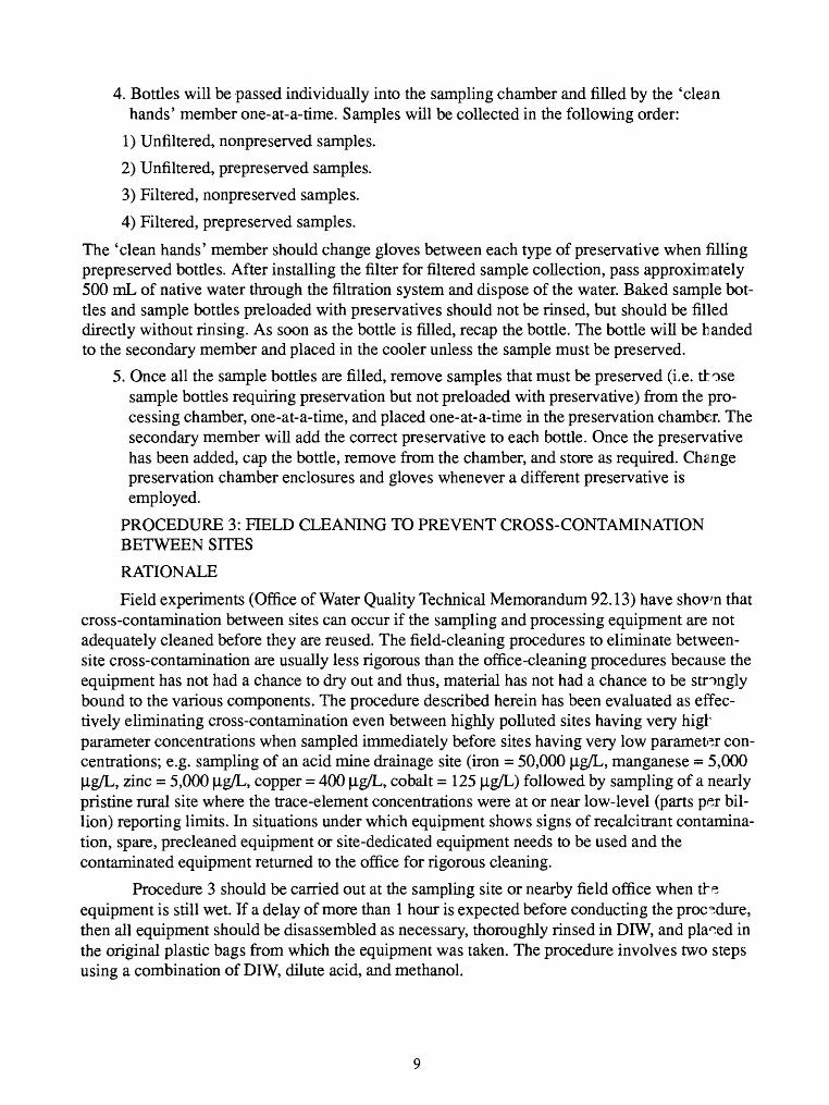
4. Bottles will be passed individually into the sampling chamber and filled by the 'clean hands' member one-at-a-time. Samples will be collected in the following order:
1) Unfiltered, nonpreserved samples.
2) Unfiltered, prepreserved samples.
3) Filtered, nonpreserved samples.
4) Filtered, prepreserved samples.
The 'clean hands' member should change gloves between each type of preservative when filling prepreserved bottles. After installing the filter for filtered sample collection, pass approximately 500 mL of native water through the filtration system and dispose of the water. Baked sample bot tles and sample bottles preloaded with preservatives should not be rinsed, but should be filled directly without rinsing. As soon as the bottle is filled, recap the bottle. The bottle will be handed to the secondary member and placed in the cooler unless the sample must be preserved.
5. Once all the sample bottles are filled, remove samples that must be preserved (i.e. those sample bottles requiring preservation but not preloaded with preservative) from the pro cessing chamber, one-at-a-time, and placed one-at-a-time in the preservation chamber. The secondary member will add the correct preservative to each bottle. Once the preservative has been added, cap the bottle, remove from the chamber, and store as required. Change preservation chamber enclosures and gloves whenever a different preservative is employed.
PROCEDURE 3: FIELD CLEANING TO PREVENT CROSS-CONTAMINATION BETWEEN SITES
RATIONALE
Field experiments (Office of Water Quality Technical Memorandum 92.13) have shown that cross-contamination between sites can occur if the sampling and processing equipment are not adequately cleaned before they are reused. The field-cleaning procedures to eliminate between- site cross-contamination are usually less rigorous than the office-cleaning procedures because the equipment has not had a chance to dry out and thus, material has not had a chance to be strongly bound to the various components. The procedure described herein has been evaluated as effec tively eliminating cross-contamination even between highly polluted sites having very high parameter concentrations when sampled immediately before sites having very low parameter con centrations; e.g. sampling of an acid mine drainage site (iron = 50,000 |ig/L, manganese = 5,000 |ig/L, zinc = 5,000 |ig/L, copper = 400 |ig/L, cobalt = 125 |ig/L) followed by sampling of a nearly pristine rural site where the trace-element concentrations were at or near low-level (parts per bil lion) reporting limits. In situations under which equipment shows signs of recalcitrant contamina tion, spare, precleaned equipment or site-dedicated equipment needs to be used and the contaminated equipment returned to the office for rigorous cleaning.
Procedure 3 should be carried out at the sampling site or nearby field office when the equipment is still wet. If a delay of more than 1 hour is expected before conducting the procedure, then all equipment should be disassembled as necessary, thoroughly rinsed in DIW, and placed in the original plastic bags from which the equipment was taken. The procedure involves two steps using a combination of DIW, dilute acid, and methanol.
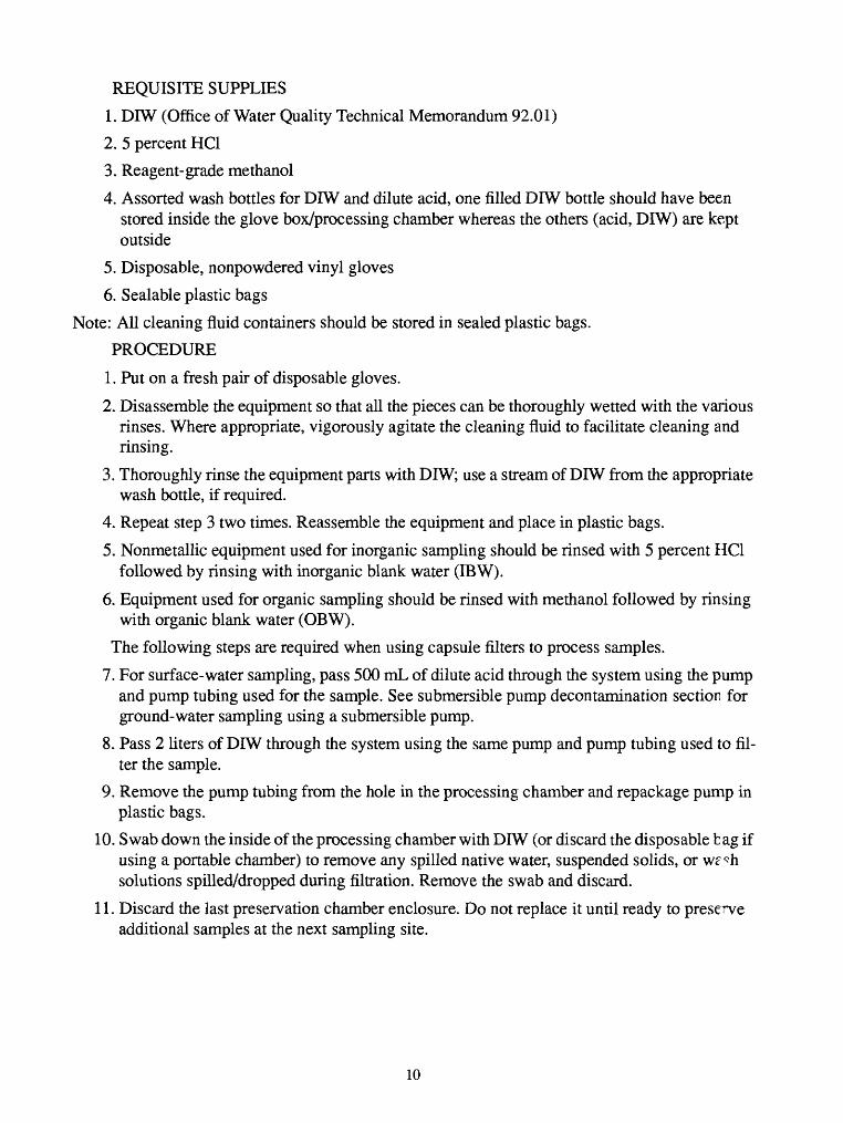
REQUISITE SUPPLIES
1. DIW (Office of Water Quality Technical Memorandum 92.01)
2. 5 percent HC1
3. Reagent-grade methanol
4. Assorted wash bottles for DIW and dilute acid, one filled DIW bottle should have been stored inside the glove box/processing chamber whereas the others (acid, DIW) are kept outside
5. Disposable, nonpowdered vinyl gloves
6. Scalable plastic bags
Note: All cleaning fluid containers should be stored in sealed plastic bags.
PROCEDURE
1. Put on a fresh pair of disposable gloves.
2. Disassemble the equipment so that all the pieces can be thoroughly wetted with the various rinses. Where appropriate, vigorously agitate the cleaning fluid to facilitate cleaning and rinsing.
3. Thoroughly rinse the equipment parts with DIW; use a stream of DIW from the appropriate wash bottle, if required.
4. Repeat step 3 two times. Reassemble the equipment and place in plastic bags.
5. Nonmetallic equipment used for inorganic sampling should be rinsed with 5 percent HC1 followed by rinsing with inorganic blank water (IBW).
6. Equipment used for organic sampling should be rinsed with methanol followed by rinsing with organic blank water (OBW).
The following steps are required when using capsule filters to process samples.
7. For surface-water sampling, pass 500 mL of dilute acid through the system using the pump and pump tubing used for the sample. See submersible pump decontamination section for ground-water sampling using a submersible pump.
8. Pass 2 liters of DIW through the system using the same pump and pump tubing used to fil ter the sample.
9. Remove the pump tubing from the hole in the processing chamber and repackage pump in plastic bags.
10. Swab down the inside of the processing chamber with DIW (or discard the disposable b ag if using a portable chamber) to remove any spilled native water, suspended solids, or w^h solutions spilled/dropped during filtration. Remove the swab and discard.
11. Discard the last preservation chamber enclosure. Do not replace it until ready to preserve additional samples at the next sampling site.
10
The following steps are required only if a plate filtration system is used to process samples.
12. Break open the filtration system inside the processing chamber and carefully remove the used membrane filter. Try to keep handling to a minimum so as not to dislodge any of the sediment and dispose of used filter. Remove the used filter, inside the plastic bag, from the processing chamber.
13. Using a wash bottle filled with DIW, thoroughly washdown all the various removable parts of the system. Pay particular attention to any grooves or crevices, any 'O' rings, and any support structures for the filter where sediment or organic matter might be trapped.
14. Put the system back together again and attach the short piece of tubing to the filtration out let.
15. For surface-water sampling, pass 500 mL of dilute acid through the system using the same pump and pump tubing used to filter the sample. Force the acid solution to cover and rinse the entire filtration system by alternately squeezing and releasing the short piece of tubing attached to the system outlet.
16. Pass 2 liters of DIW through the system using the same pump and pump tubing used to fil ter the sample.
17. Remove the pump tubing from the hole in the processing chamber and repackage pump in double plastic bags.
18. If the processing chamber is nonportable, swab down the inside with DIW to remove any spilled native water, suspended solids, or wash solutions spilled/dropped during removal of the filter, etc. Remove the swab and discard. If the processing chamber is a portable unit, discard the enclosure cover and replace with a new one.
19. Discard properly the last preservation chamber enclosure used. Do not replace enclosures until ready to preserve additional samples at the next sampling site.
12.3 Ground-water sampling pump decontamination Decontamination of submersible sampling pumps conducted under office conditions, between sampling trips, will be as follows:
1. Personnel will put on gloves and clean standpipes with detergent and tap water, followed by an acid rinse, followed by a deionized water (DIW) rinse.
2. External surfaces of pump and sample line will be washed in 1 to 2 percent (volume) deter gent solution and rinsed with tap water.
3. Detergent solution will be pumped through sample lines for two to four pump/line volume cycles from a sink or standpipe. Detergent solution may be recirculated.
4. Tap water will be pumped through sample lines until there is no evidence of detergent remaining.
5. Rinse pump exterior with DIW and place pump into DIW standpipe. Fill with DIW above pump intake. Pump DIW through sample line for at least three line volumes without recir- culating. Step 5 is the final step for inorganic-only analyses. Step 6 will continue the pro cess for organic sampling.
11
6. Wearing latex gloves, personnel shall place the pump in a methanol standpipe and fill with reagent or HPLC-grade methanol to above pump intake. Pump sufficient methanol to rinse the sample line once. Pour unused methanol back into bottle, add DIW to standpipe, and pump at least twice the line volume through the pump without recirculating.
7. Enclose pump in plastic bags or wrap and place a large plastic bag or wrap over pump and reel assembly.
Decontamination of submersible sampling pumps conducted under field conditions, between indi vidual sampling sites, will be as follows:
1. Wearing gloves and using precleaned cleaning equipment, pump 0.1 to 0.5 percent deter gent/tap water solution through pump from standpipe or bucket for two to three pump/line volumes. Solution may be recirculated.
2. Pump tap water through pump until there is no evidence of detergent remaining. Do not recirculate water.
3. Rinse pump exterior with DIW, and pump DIW through pump and lines for four line vol umes.
4. Enclose pump and lines in plastic bags or wrap.
Note: All new equipment also will be cleaned prior to use because manufacturing, handling, stor age, and shipping can leave chemical residues.
12.4 Enzyme-linkedImmunosorbent Assay Soil and water screening for contaminants such as DDT by enzyme-linked immunosorbent assay (ELISA) will be conducted as needed, following prescribed ELISA kit manufacturers methods. DDT ELISA will be carried out at SWMU No. 9 using SW-846 Method 4042. The method uses a polyclonal antibody specific for DDT (isomers and metabolites) and is sensitive to concentrations above 0.2,1.0, and 10 mg/Kg (ppm) depending on the particular kit used. Measurements are based on competitive binding of DDT extracted f-om samples with a DDT-enzyme conjugate in antibody-coated test tubes. A color reagent is added to each of the sample tubes; the reagent reacts with the test-tube-bound DDT-enzyme conjugate to generate a blue color. HC1 is added to produce a final yellow color that is monitored at 450 non- ometers (nm) using a spectrophotometer. Because there is a fixed number of antibody binding sites in each tube and the same amount of DDT-enzyme conjugate is added to each tube, the degree of coloration in the individual tubes is inversely related to the sample extract DDT concen tration. A summary of the method is included here. However, personnel will follow the instruc tions provided by the supplier of the DDT soil test kit.
1. A 5 gram soil sample is extracted by swirling the soil for 2 minutes with 5 mL of methanol in the polyethylene vials containing stainless steel ball bearings (supplied with kits).
2. The extract is filtered and retained for analysis; extracts may be stored at 2 to 7 °C in the dark at this stage.
3. Aliquots of the negative control, calibrators, and diluted sample extracts are transferred to the antibody tubes containing assay diluent. DDT-enzyme conjugate is transferred to each tube and the tubes are incubated.
4. The antibody tubes are then washed to remove unbound DDT and DDT-enzyme conjugate. Enzyme substrate is added to cause the color change reaction.
12
5. The IN HC1 stop solution is added to fix color development.
6. DDT concentration is measured using a photometer referenced to one of the calibrator tubes. The resulting color is inversely related to the DDT concentration in the soil extracted. The absorption difference between the calibrators and the negative contrc1 is evaluated as part of method quality control.
While the method does afford a qualitative assessment of compound concentration, it will not differentiate between the DDT isomers and metabolites. The method detects the preserve of DDT isomers and metabolites to varying degrees of sensitivity and yields a combined concentra tion of all present as a result. Because the DDT metabolites (DDD and DDE) are also contami nants, this lack of specificity is acceptable, even desirable, for field screening.
The USGS has intensive, ongoing research and application of ELISA methodology; as method development evolves, improvements will be adopted for the Fort Chaffee project. ELISA techniques are available for compounds other than DDT (described here), and the ELISA tech nique will be used for others where ever the method offers data of a quality to support project objectives.
7.2.5 Soil and sediment sample collection Soil-core samples will be collected using a stainless- steel 3-inch manually operated hand auger for shallow samples or a 1 3/8-inch (i.d.) or 2 1/2-inch (i.d.) or other suitable stainless-steel split spoon sampler for deeper samples. Samples will be col lected from a 2-ft interval that brackets the selected sampling depth interval. Split-spoon ssmples will be collected as follows:
1. Start from the surface or drill to the desired starting depth.
2. Mount the split-spoon sampler on the appropriate drive rod or drill rod and attach the driv ing anvil to the top of the assembly.
3. Place the split-spoon sampler at the desired starting point and drive 18 to 24 inches using a hammer-drop system (50 to 140 Ib hammer) as described in ASTM method D1586 if sam pling from a drilling unit. If not sampling from a drilling unit, a smaller, manually lifted hammer will be used to drive the sampler.
4. Retrieve the split-spoon sampler, separate the halves, and describe the sample.
5. Remove subsamples, place into appropriate containers, and chill.
6. Decontaminate sampler as described in section 1.2.2.
Surface "grab" samples of sediment and soil will be collected using a stainless-steel ?coop or hand-driven auger.
7.2.6 Water-level measurements Static water-level measurements will be taken at all wells and piezometers using a steel tape, electric tape, or pressure transducer that has been decontaminated. Water-level measurements will be plotted to map the potentiometric surface of the shallow aqui fer. Water levels will be measured from an established measuring point on the top edge of the cas ing. The depth of the water will be recorded to the nearest 0.01 ft; the measurement will be repeated until two consecutive measurements are within 0.02 ft. Water-level measurements should be taken under static conditions, i.e. prior to purging and sampling. All measurements will be recorded in the proper field book with each measurement's well identification, date, time, and
13
water level noted. If an electric tape or pressure transducer is used, the serial number and desTip- tion of the equipment will be recorded. Water levels at a specific site will be measured withir the shortest time span possible to minimize error due to natural fluctuations of the water table.
Generally, soil borings will be placed to define boundaries-areal and vertical-of contami nated zones through conducting chemical analyses on samples collected and to determine general soil physical and chemical hydrogeological characteristics (geotechnical sampling). Wells and test holes may also be used for soil sampling. Borings used for soil sampling will be drilled en a site-specific basis for sampling. The number of these boreholes, horizons sampled, and the typ^ of sampling to be performed will be specified in the individual site work plans.
7.2.7 Wipe sampling-Wipe samples will be collected to detect contamination from spills onto hard "smooth" surfaces such as metal, wood, concrete, plastic, and glass. To maintain a level of sample-area consistency, a template will be used to expose a constant area (for example, 100 cm2) to be wiped. Samples areas of 100 cm2 x 6 (the number of laboratory methods) each will be grid- ded with templates and sampled randomly. The sampling surface areas will be visually checked for consistent roughness, porosity, and fractures.
For wipe sampling for detection of semivolatile organics, pesticides and PCB's, herbicides, and non-metals, an EPA contract laboratory will provide gauze pads prewetted with hexane, shipped in metal containers. After wiping, the gauze pad will be placed back in the metal con tainer and returned to the laboratory. A separate wipe will be required for each analysis method (ICP, CVAA, GFAA, GC/MS, GC/ECD).
For wipe sampling for detection of metals, the use of Whatman 41 or equivalent filters is recommended instead of gauze pads. These filters are generally used in laboratories for filtering metals digestates and are relatively free of contamination. The wetting agent used for metals ram- pling will be dilute nitric acid. After sampling, the filter wipes are placed in plastic bottles or ziplock bags for shipment to the laboratory.
Unfortunately, wipe sampling is not quantitative because of the fairly large variability in several component parts of sampling and the relative inefficiency of analyte extraction from the wipe. For these reasons, wipe test results are not always reproducible. Every effort will be mrde to maintain consistency of component parts of sampling such as consistent wiping pressure, wip ing pattern, area to be samples, wipe type, holding time, and porosity of surface sampled. The resultant set of samples should be representative and comparable to other wipe samples within the group. Results will be reported in micrograms/wipe.
The procedures for wipe sampling are as follows:
1. The sampler arrives at a sampling site and determines the exact location where the 100 cm sample will be taken. The sample location may be marked or framed by a decontaminated plastic 10 cm x 10 cm template.
2. The sampler must be conscious of the possibility of cross-contamination during all stages of wipe sampling.
3. All surfaces must be wiped with as uniform pressure as possible.
14
4. The sampler proceeds wiping from left to right in rows from the top to the bottom of the framed sampling area. The sample area is wiped again with the same uniform pressure in columns from the top to the bottom from the left to the right side covering the entire framed area. The objective is to systematically, thoroughly, and consistently wipe th a, entire framed area twice, each time from a different direction and orientation.
5. After sampling, the gauze wipes are placed in the metal container and filter wipes (for metals) are placed in a plastic bottle or ziplock bag for shipment to the laboratory.
Template decontamination procedures will follow Procedure 1 in section 1.2.2 Ground- Water Sampling.
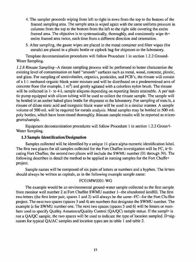
1.2.8 Rinsate Sampling--A rinsate sampling process will be performed to better characterize the existing level of contamination on hard "smooth" surfaces such as metal, wood, concrete, plastic, and glass. For sampling of semivolatiles, organics, pesticides, and PCB's, the rinsate will consist of a 1:1 methanol-organic blank water mixture and will be distributed on a predetermined area of concrete floor (for example, 1 m2) and gently agitated with a colorless nylon brush. The rinsate will be collected in 1- to 4-L sample aliquots depending on reporting limits attainable. A perstal- tic pump equipped with silicon tubing will be used to collect the rinsate sample. The sample will be bottled in an amber baked glass bottle for shipment to the laboratory. For sampling of mete Is, a rinsate of dilute nitric acid and inorganic blank water will be used in a similar manner. A sample volume of 500-mL will be required for metals analysis. Metal samples may be bottled in 500-mL poly bottles, which have been rinsed thoroughly. Rinsate sample results will be reported as micro- grams/sample.
Equipment decontamination procedures will follow Procedure 1 in section 1.2.2 Ground- Water Sampling.
1.3 Sample Identification/DesignationSamples collected will be identified by a unique 11-place alpha-numeric identification label.
The first two places for all samples collected for the Fort Chaffee investigation will be FC, irdi- cating Fort Chaffee; the second two places will include the SWMU number (01 through 39). The following describes in detail the method to be applied in naming samples for the Fort Chaffer project.
Sample names will be composed of six pairs of letters or numbers and a hyphen. The letters should always be written as capitals, as in the following example sample name:
FC01MW0201-WG
The example would be an environmental ground-water sample collected as the first sample from monitor well number 2 at Fort Chaffee SWMU number 1-the abandoned landfill. The first two letters (the first letter pair, spaces 1 and 2) will always be the same~FC~for the Fort Ch^ffee project. The next two spaces (spaces 3 and 4) are numbers that designate the SWMU number. The example is for SWMU number one. The next two spaces (spaces 5 and 6) will be letters or num bers used to specify Quality Assurance/Quality Control (QA/QC) sample status. If the sample is not a QA/QC sample, the two spaces will be used to indicate the type of location sampled. Desig nators for typical QA/AC samples and location types are in table 1 and table 2.
15
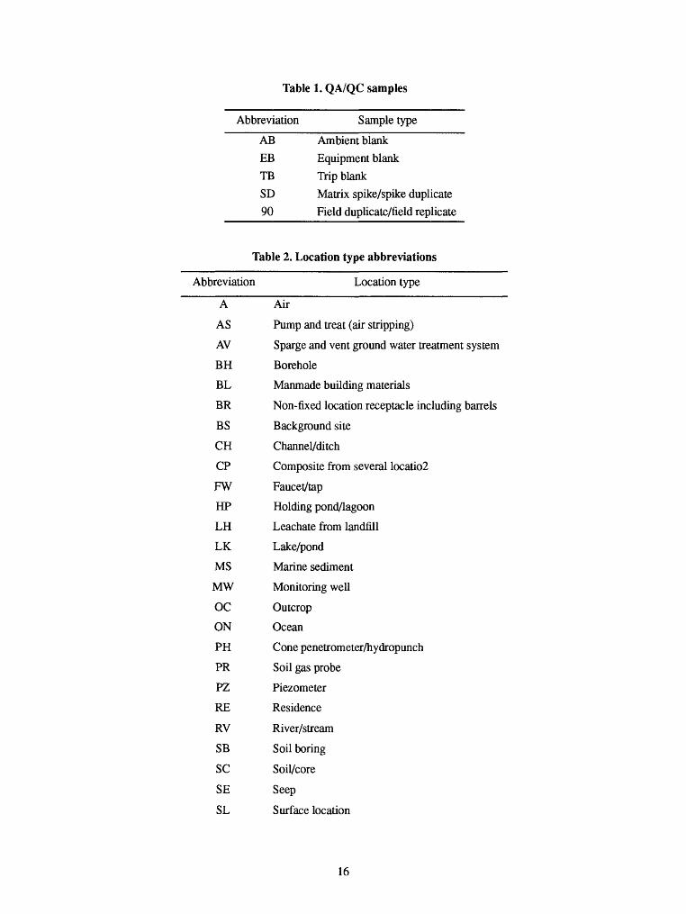
Table 1. QA/QC samples
Abbreviation Sample type
AB Ambient blank
EB Equipment blank
TB Trip blank
SD Matrix spike/spike duplicate
90 Field duplicate/field replicate
Table 2. Location type abbreviations
Abbreviation Location type
A Air
AS Pump and treat (air stripping)
AV Sparge and vent ground water treatment system
BH Borehole
BL Manmade building materials
BR Non-fixed location receptacle including barrels
BS Background site
CH Channel/ditch
CP Composite from several Iocatio2
FW Faucet/tap
HP Holding pond/lagoon
LH Leachate from landfill
LK Lake/pond
MS Marine sediment
MW Monitoring well
OC Outcrop
ON Ocean
PH Cone penetrometer/hydropunch
PR Soil gas probe
PZ Piezometer
RE Residence
RV River/stream
SB Soil boring
SC Soil/core
SE Seep
SL Surface location
16
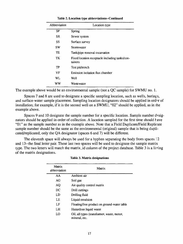
Table 2. Location type abbreviations Continued
Abbreviation Location type
SP Spring
SR Sewer system
SS Surface survey
SW Storm water
TE Tank/pipe removal excavation
TK Fixed location receptacle including tanks/con tainers
TP Test pit/trench
VF Emission isolation flux chamber
WL Well
WW Wastewater
The example above would be an environmental sample (not a QC sample) for SWMU no. 1.
Spaces 7 and 8 are used to designate a specific sampling location, such as wells, borings, and surface-water sample placement. Sampling location designators should be applied in ord0J of installation; for example, if it is the second well on a SWMU, "02" should be applied, as in the example above.
Spaces 9 and 10 designate the sample number for a specific location. Sample number desig nators should be applied in order of collection. A location sampled for the first time should h ave "01" as the sample number as in the example above. Note that a Field Duplicate/Field Replicate sample number should be the same as the environmental (original) sample that is being dupli cated/replicated, only the QA designator (spaces 6 and 7) will be different.
The eleventh space will always be used for a hyphen separating the body from spaces 12 and 13-the final letter pair. These last two spaces will be used to designate the sample matrix type. The two letters will match the matrix_id column of the project database. Table 3 is a listing of the matrix designations.
Table 3. Matrix designations
Matrix ... .,, Matnx abbreviauon
AA Ambient airAG Soil gasAQ Air quality control matrixDC Drill cuttingsLD Drilling fluidLE Liquid emulsionLF Floating/free product on ground-water table
LH Hazardous liquid wasteLO Oil, all types (transformer, waste, motor,
mineral, etc.
17
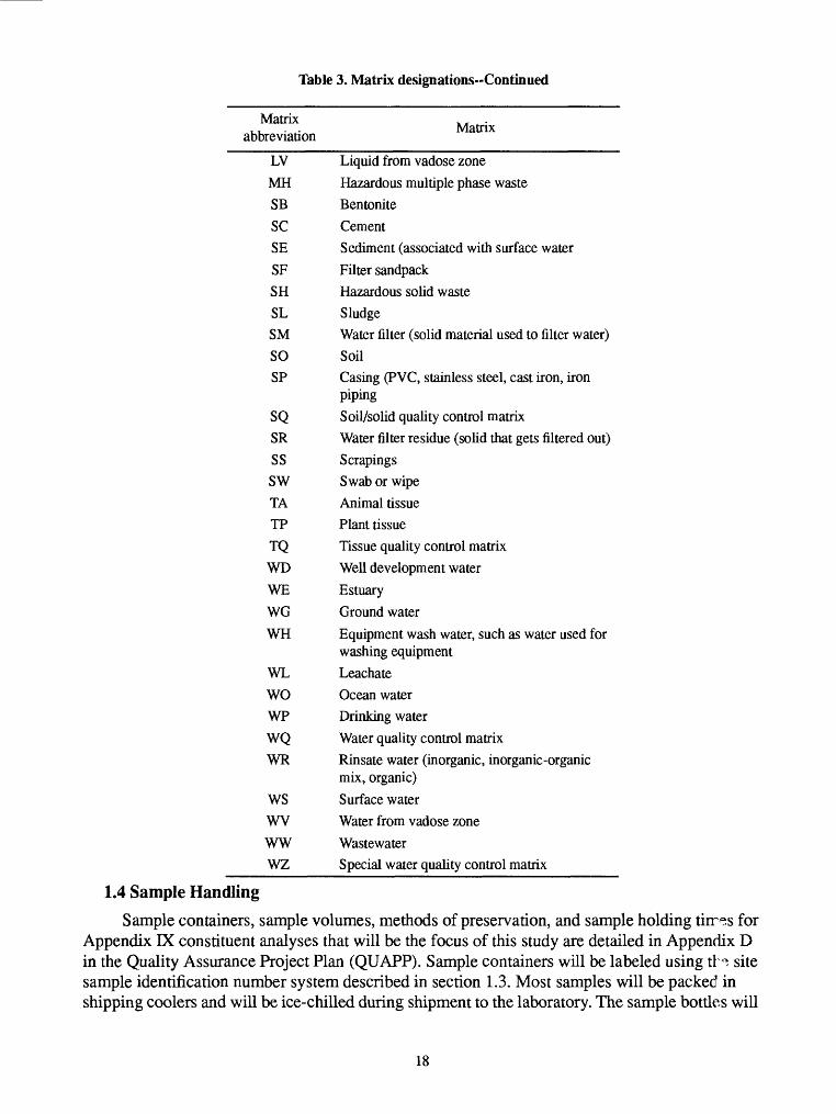
Table 3. Matrix designations-Continued
Matrix abbreviation Matrix
LV Liquid from vadose zoneMH Hazardous multiple phase wasteSB BentoniteSC CementSE Sediment (associated with surface waterSF Filter sandpackSH Hazardous solid wasteSL SludgeSM Water filter (solid material used to filter water)SO SoilSP Casing (PVC, stainless steel, cast iron, iron
pipingSQ Soil/solid quality control matrixSR Water filter residue (solid that gets filtered out)SS ScrapingsSW Swab or wipeTA Animal tissueTP Plant tissueTQ Tissue quality control matrixWD Well development waterWE EstuaryWG Ground waterWH Equipment wash water, such as water used for
washing equipmentWL LeachateWO Ocean waterWP Drinking waterWQ Water quality control matrixWR Rinsate water (inorganic, inorganic-organic
mix, organic)WS Surface waterWV Water from vadose zoneWW WastewaterWZ Special water quality control matrix
1.4 Sample Handling
Sample containers, sample volumes, methods of preservation, and sample holding tirr^s for Appendix IX constituent analyses that will be the focus of this study are detailed in Appendix D in the Quality Assurance Project Plan (QUAPP). Sample containers will be labeled using tH site sample identification number system described in section 1.3. Most samples will be packed in shipping coolers and will be ice-chilled during shipment to the laboratory. The sample bottles will
18
be sealed in plastic bags to protect the labels from water damage. The associated chain-of-custody forms will be placed in the cooler in a sealed plastic bag at the time the samples are placed in the ice chest.
Shipping containers for chilled samples will be metal or high-impact plastic ice chests. Shipping containers for samples not requiring chilling will meet U.S. Geological Survey and U.S. Department of Transportation requirements for shipment.
The chain-of-custody forms placed inside each shipping container will identify the contents and destination. The outside of the shipping container will be clearly marked with the origin rnd destination of the shipment. A shipping custody seal will be placed across the lid of the shipping ice chest Information on special handling (if any) of chilled water and soil samples in containers of any sample shipment will be clearly identified on the outside of each container. Overnight ship ment via commercial air carriers will be scheduled and implemented.
1.5 Sample CustodySample custody is important for ensuring that samples are collected, protected, stored, han
dled, analyzed, and disposed of properly by authorized personnel. A person involved in the initial collection of the sample in the field will be appointed as having initial custody of the samples. That person will ensure that field data associated with the sample are documented and that the- sample container is labeled. Standard procedures for handling, packaging, and shipping samples will be followed, and the chain-of-custody procedure will be continued when custody is trans ferred to the laboratory after shipment of the samples.
A sample is in your custody if:
1. it is in your possession,
2. it is in your view after being in possession,
3. it was in your possession and you locked it up, or
4. it is in a designated secure area.
Samples in containers will be identified using adhesive-backed sample labels. Sample laHls will be attached to the sample containers immediately after filling the containers. The following information will be entered, as a minimum, with waterproof ink on the sample label:
1. field sample ID number (see section 1.3),
2. date,
3. time,
4. sampled by (collector), and
5. preservative.
The analytical services request form includes the chain-of-custody record. This form will be filled out for each sample set at the time of sampling. The sampler will keep one copy of the ser vices request form and place the other copy in the sample shipping container with the samples going to the laboratory. Transfer of custody will be recorded in the signature block of the chair-of custody form. At the completion of analysis, the laboratory will return a completed copy of tire form showing the chain-of-custody record within the laboratory.
19
1.6 Aquifer Testing
The objective of any aquifer tests conducted will be to quantify aquifer hydrogeologi^al parameters. Aquifer test procedures will vary depending on the data required and type of test cho sen to yield the information needed; data needs and the aquifer test methods to be applied are site- specific elements and will be detailed in the individual site work plans. Wells that will be tested will also be delineated in the work plans.
Most aquifer testing to be conducted is expected to be slug testing. Reasons for this include: (1) the difficulty of maintaining a constant discharge in heterogeneous deposits common at the facility, (2) the heterogeneity of the aquifer may result in multiple boundary conditions and yield data that are difficult or impossible to interpret, (3) pumping test data from low-yield wells (less than 2 gal/min) are unreliable because of maintaining a constant discharge as mentioned above, and the fact that the well can go dry, and (4) stressing a potentially contaminated aquifer c?.n spread contamination. Pump tests will be conducted only under well constrained circumstances where the concerns stated above are not significant and there is a need for the more extensive data offered by pumping tests.
7.6.7 Equipment--^, steel tape or electrical water-level tape will be used to measure a pretext water level and to calibrate any pressure transducers to be used. Water levels during testing may be measured by electrical water-level tap and water levels recorded manually or by installing pressure transducers and an automatic data logger. A submersible pump will be used for cc nduct- ing pumping tests. Discharge will be monitored and recorded at timed intervals in the field notes. For slug tests, a predetermined volume will be removed from the borehole if a negative slug approach is to be used, or a predetermined volume of deionized water will be added to the bore hole if a positive slug approach is to be used. For negative-slug tests, a large capacity baile~ will be used to achieve rapid removal of the slug volume or a calibrated PVC slug will be removed from the well after water levels have reached equilibrium with the PVC slug in place. For posi tive-slug tests, an 8-ft standpipe with a gate valve will be used for near-instantaneous addition of the slug volume.
7.6.2 Slug Test Procedures-^ a PVC slug is to be used, the slug will be calibrated by placir^ it in a PVC pipe filled with water. Sand will be poured in the slug until a reference point is floatng a specified distance (which will vary with the column of water in the well being tested) above the water in the pipe. Because of the short distance between the water level and the bottom of some wells, care will be taken so the slug will be calibrated so as not to touch the bottom of the well during the test period. The slug will be removed from the calibration PVC pipe, and the column of water in feet that it displaced will be recorded in the field notebook. This procedure will allow cal culation of the volume of water that the slug will displace when it is lowered into the hole and the volume of water the PVC slug represents as removed when the slug taken from the well at the start of the test.
Prior to the test, static water level in the monitor well will be measured with a steel or elec trical water-level tape. An electrical water-level tape or a pressure transducer device may be used for measuring water levels during the test. If a pressure transducer is to be used, the transducer will be placed in the well and calibrated by taking readings at measured increments below the water surface and recording the readings in the field notebook. The slug will be rapidly added or taken out, and water-level monitoring--whether by electrical tape or by pressure transducer-will
20
begin with introduction of the slug and continue (periodically in the case of measurement by elec trical tape) until the water level stabilizes at or near original level. All downhole equipment will be decontaminated in accordance with the procedures described herein.
1.6.3-Pumping Test Procedure-Wells will be selected based on site-specific conditions that will produce good results (for example, aquifer continuity, lack of multiple boundary conditions, and hydrologic communication). Water levels in selected monitor wells and the control well will be measured with a steel or electrical water-level measurement tape. The water level in the control well will be monitored after installing the pump until the water returns to its original level. Elec trical water-level tape or pressure transducers may be used for water-level measurements during the tests. If pressure transducers will be used, the transducers will be placed in the wells and cali brated by taking readings at measured increments below the water surface. The pressure transduc ers will be operated for a minimum of 2 hours prior to turning on the pump to monitor for wner- level trends. The duration of the pump test will depend on the hydrologic conditions (confined, unconfined, specific yield) and will be delineated in the site work plans. The submersible pump will be turned on. The discharge must be constant during the test; therefore, discharge will be reg ulated to keep discharge at less than the wells' full capacity. The discharge water will be stored in 55-gallon drums for disposal if possibility of contaminated water production is perceived. D : s- charge will be monitored throughout the test. Pump test data will be recorded through the test. The downhole equipment will be decontaminated in accordance with the procedures detailed herein.
1.6.4 Data Management and Analysis-A bound field notebook will be used to record pertinent information relative to the aquifer tests. The notebook will be used to record pretest water level, field conditions, slug volume data, test conditions, and discharge rates as applicable. Data analysis will consist of type curve matching techniques that have developed for specific hydrogeolog^c conditions. The type curves are based on mathematical models of well drawdown for specific sit uations.
2.0 Field Measurements
2.1 Parameters
Several parameters will be tested in the field as part of the analytical protocol for samples. Water samples will be field tested for temperature, pH, specific conductance, and alkalinity using methods discussed in the following section. Soil and sediment samples will be monitored for total volatile organic concentrations with an OVA. Soil-gas samples will be analyzed in the field with a portable gas chromatograph.
2.2 Equipment Calibration
The field test equipment that will be used, the frequency of calibration, and the calibration procedures are as follows:
Thermometers - Mercury-free thermometers will be used. New thermometers will be cali brated at 0 and 25 °C in the field office or main office laboratory with a National Bureau of Stan dards (NBS) calibrated thermometer. Thermometers will be inspected for breakage or liquid- column separation before each use. Field thermometers will be checked monthly.
21
Calibration is performed by partially immersing the thermometer and an NBS calibrated thermometer in a 1-liter glass beaker filled with crushed ice and water. Let the thermometers sit in the ice and water mixture for 5 minutes and compare readings while the thermometers are still immersed in the solution. Repeat calibration with a water sample stabilized at room temperature near 25 °C. Reject any thermometer not reading within ±0.5 °C of the NBS calibrated thermome ter. Decontamination of the thermometers is performed by rinsing with deionized water and air drying.
pH Meter (Beckman Model 21, Orion Model 250, Hydrolab, or comparable unit) - -Cali brate instrument per manufacturers' recommended procedure using two pH buffer solutions~pH 7 and pH 4 or pH 10. Calibration will be done prior to first use each day, and then every 41 ours. Calibration will be checked prior to each measurement series at one location. Buffer solution must be within 5 °C of sample temperature. Buffer solutions will be kept separate from samples. Instru ment probes will be rinsed with deionized water between all measurements to prevent cross-con tamination and decontamination.Meters will be checked at the end of the day and any drift in calibration recorded in the field notebook, and measurements adjusted accordingly if the drift exceeds accuracy limits of ±0.2 pH.
Specific Conductance Meter (Beckman RB6, Labline Micromho, Orion Model 122, Fydro- lab, or comparable unit) - The instrument will initially be calibrated in the laboratory using three standards, and calibrated daily per manufacturer's recommended procedure using a KCl-type standard reference solution of known value within 1.0 percent accuracy. The standard reference solutions will be selected to be close to anticipated range of field measurements. Readings will be taken after meter response has stabilized.
Turbidity (Hach DREL-5 spectrophotometer or a comparable unit) - Calibrate meter in field by using deionized water blank to zero meter. Sample (25 mL) is then measured directly in spec trophotometer. Precision on the method is ±2 turbidity units.
Alkalinity - Alkalinity will be measured in the field using a calibrated pH meter. Clear sam ple aliquots of 50 mL will be titrated incrementally against 0.16N or 1.60N standard sulfuri^ acid solution using a Hach digital titrator kit. The standard acid is dispensed from syringe cartridges that are designed for use with the kit. The titration data, pH versus volume of acid, will be recorded in the daily logbooks. The alkalinity values will be calculated at a later date using the incremental technique by calculating the maximum change in pH for a given increment of acid.
Organic Vapor Analyzer (OVA) - The instrument is factory calibrated with respect to meth ane by the manufacturer. This calibration will be checked against a standard gas of known meth ane concentration just before use in accordance with the manufacturer's manual. If the instrument range is changed, the calibration will be rechecked.
Gas Chromatograph - Calibrate instrument per manufacturer's recommended procedure by injecting standard gas mixtures or by using the head-space technique. Using the head-space tech nique, dissolve a measured quantity of benzene, toluene, xylene, or dichlorobenzene in app~oxi- mately 20 to 30 mL of distilled water in a volatile organic analyses (VOA) vial and allow tH mixture to reach equilibrium with the vapor in the space above the liquid. Inject a known quantity of the vapor from the space above the liquid into the gas chromatograph and calibrate for tr/5 retention time and the liquid concentration of the compound(s).
22
Calibration by this procedure will be used to define general subsurface plumes of volatile organic compounds in soil gases and is not intended to quantify specific organic compounds that may be in the soil gases.
2.3 Equipment MaintenanceThe following maintenance checks will be made on the equipment used in the field:
Thermometer - Thermometers will be checked, before using, for column separation, cracks, chips, or scratches. If any separation, cracks, chips, or scratches are found, the thermometer will be discarded.
pH Meter - The battery charge level will be checked daily. Probes and connectors will b^ checked daily prior to any field operation. The pH meter will be calibrated daily prior to the com mencement of any field sampling.
Specific Conductance Meter - The battery charge level will be checked daily. Probes will be checked daily for cracks or any other damage. The specific conductance meter will be calibrated each day with standard solutions prior to the commencement of sampling.
Turbidity I Spectrophotometer - The battery charge level will be checked daily. Probes and connectors will be checked daily prior to operation. The meter will be adjusted to a reading of zero for background before use.
Organic Vapor Analyzer - The battery charge level, gas content, probe, and connectors will be checked daily prior to any field operation. The meter will be adjusted to a reading of zero for background before use.
Field Gas Chromatograph - The battery charge level will be checked daily prior to com mencement of field sampling. The carrier gas supply will be checked prior to use and then per od- ically during the day. The baseline for the columns in use will be checked prior to the day's operation by injecting a sample of clean air.
3.0 FIELD QUALITY-CONTROL (QC) SAMPLES
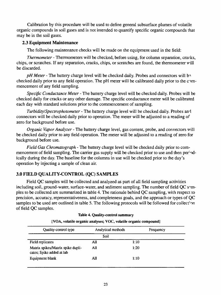
Field QC samples will be collected and analyzed as part of all field sampling activities including soil, ground-water, surface-water, and sediment sampling. The number of field QC sam ples to be collected are summarized in table 4. The rationale behind QC sampling, with respect to precision, accuracy, representativeness, and completeness goals, and the approach or types of QC samples to be used are outlined in table 5. The following protocols will be followed for collection of field QC samples.
Table 4. Quality-control summary
[VGA, volatile organic analyses; VOC, volatile organic compound]
Quality-control type Analytical methods Frequency
Soil Field replicates All 1:10Matrix spikes/Matrix spike dupli- All 1:20 cates; Spike added at labEquipment blank All 1:10
23
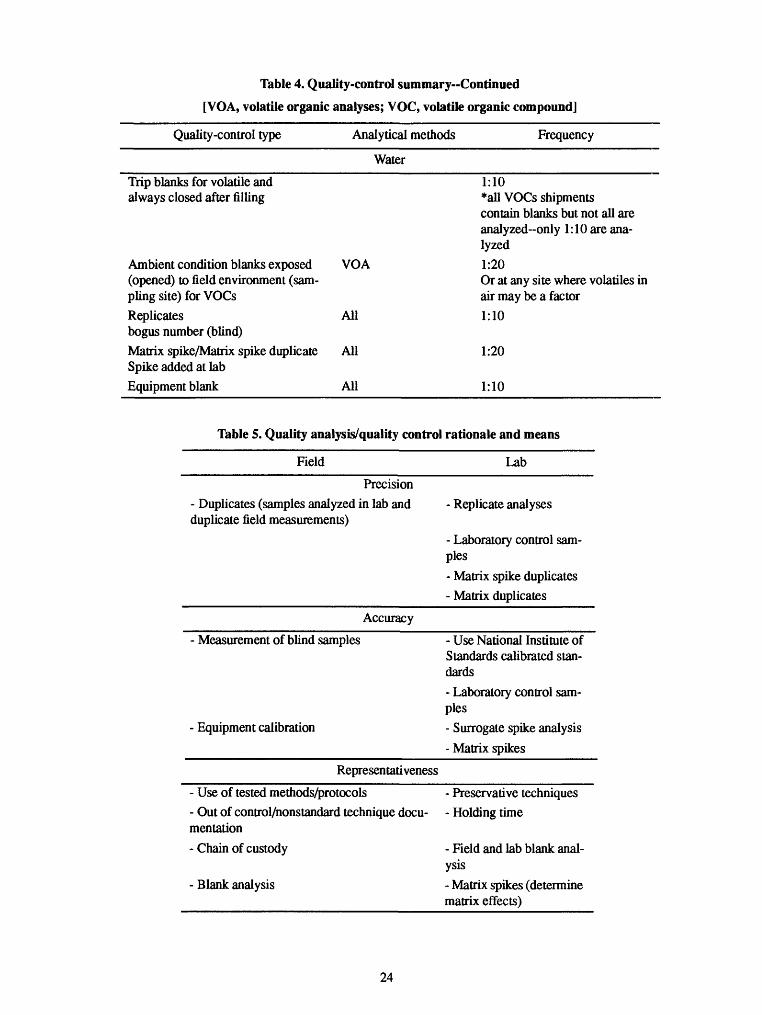
Table 4. Quality-control summary Continued
[VOA, volatile organic analyses; VOC, volatile organic compound]
Quality-control type Analytical methods Frequency
Water
Trip blanks for volatile and always closed after filling
Ambient condition blanks exposed VOA (opened) to field environment (sam pling site) for VOCsReplicates All bogus number (blind)Matrix spike/Matrix spike duplicate All Spike added at labEquipment blank All
1:10*all VOCs shipments contain blanks but not all are analyzed-only 1:10 are ana lyzed1:20Or at any site where volatiles inair may be a factor1:10
1:20
1:10
Table 5. Quality analysis/quality control rationale and means
Field Lab
Precision- Duplicates (samples analyzed in lab and duplicate field measurements)
- Replicate analyses
- Laboratory control sam ples- Matrix spike duplicates- Matrix duplicates
Accuracy
- Measurement of blind samples
- Equipment calibration
- Use National Institute of Standards calibrated stan dards- Laboratory control sam ples- Surrogate spike analysis- Matrix spikes
Representativeness
- Use of tested methods/protocols- Out of control/honstandard technique docu mentation- Chain of custody
- Blank analysis
- Preservative techniques- Holding time
- Field and lab blank anal ysis- Matrix spikes (determine matrix effects)
24
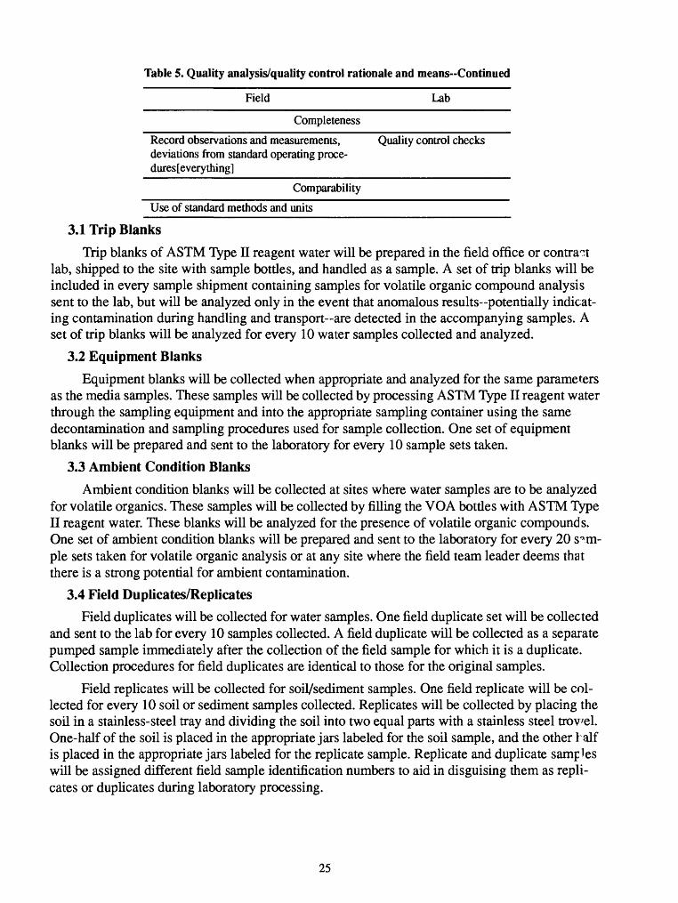
Table 5. Quality analysis/quality control rationale and means-Continued
Field Lab
Completeness
Record observations and measurements, Quality control checks deviations from standard operating proce dures [every thing]
Comparability
Use of standard methods and units
3.1 Trip Blanks
Trip blanks of ASTM Type n reagent water will be prepared in the field office or contract lab, shipped to the site with sample bottles, and handled as a sample. A set of trip blanks will be included in every sample shipment containing samples for volatile organic compound analysis sent to the lab, but will be analyzed only in the event that anomalous results-potentially indicat ing contamination during handling and transport are detected in the accompanying samples. A set of trip blanks will be analyzed for every 10 water samples collected and analyzed.
3.2 Equipment Blanks
Equipment blanks will be collected when appropriate and analyzed for the same parameters as the media samples. These samples will be collected by processing ASTM Type II reagent water through the sampling equipment and into the appropriate sampling container using the same decontamination and sampling procedures used for sample collection. One set of equipment blanks will be prepared and sent to the laboratory for every 10 sample sets taken.
3.3 Ambient Condition Blanks
Ambient condition blanks will be collected at sites where water samples are to be analyzed for volatile organics. These samples will be collected by filling the VGA bottles with ASTM Type II reagent water. These blanks will be analyzed for the presence of volatile organic compounds. One set of ambient condition blanks will be prepared and sent to the laboratory for every 20 s^rn- ple sets taken for volatile organic analysis or at any site where the field team leader deems that there is a strong potential for ambient contamination.
3.4 Field Duplicates/ReplicatesField duplicates will be collected for water samples. One field duplicate set will be collected
and sent to the lab for every 10 samples collected. A field duplicate will be collected as a separate pumped sample immediately after the collection of the field sample for which it is a duplicate. Collection procedures for field duplicates are identical to those for the original samples.
Field replicates will be collected for soil/sediment samples. One field replicate will be col lected for every 10 soil or sediment samples collected. Replicates will be collected by placing the soil in a stainless-steel tray and dividing the soil into two equal parts with a stainless steel trowel. One-half of the soil is placed in the appropriate jars labeled for the soil sample, and the other half is placed in the appropriate jars labeled for the replicate sample. Replicate and duplicate samples will be assigned different field sample identification numbers to aid in disguising them as repli cates or duplicates during laboratory processing.
25
3.5 Matrix Spikes/Matrix Spike Duplicates
The sample sets selected for matrix spike and matrix spike duplicates (MS/MSD) analysis will contain a primary soil sample and samples for duplicate spiked analysis. The MSD samples are sent to the lab where they are spiked and analyzed. One MS/MSD sample set will be p~o- cessed for every 20 samples. Samples for MS/MSD analysis will measure the effects of the sam ple matrix and provide an estimate of accuracy. These samples will all be taken from the same core barrel. Compounds and concentrations of spiking standards are given in appendix B cf the QUAPP.
MS/MSDs for water samples serve the same purpose as for soil sampling. The sample sets selected for matrix spike analysis will contain a primary water sample and samples for MS and MSD analysis. These samples will be collected during the same period of pumpage as the primary sample. One MS/MSD sample set will be processed for every 20 samples. Compounds and con centrations of spiking standards are given in appendix B of the QUAPP.
4.0 Control Parameters
The quality-assurance effort for the field investigation program has been developed to ensure and validate that error is not introduced into the data set being developed through inconsis tencies in data-collection protocols. Field-quality control checks will constitute an important seg ment of sample collection procedures in order to minimize the potential for interference or introduction of extraneous, nonrepresentative contaminants during sample collection, storage, transport, and equipment decontamination and to identify these problems if they occur.
Trip blanks, equipment blanks, duplicate or replicate samples, and ambient condition blanks will be collected, prepared, and sent to the laboratory for analysis. The analytical results will be evaluated to determine the adequacy of sample collection techniques. A description of the?e field QC samples and their frequency of collection are discussed in the previous section.
An "out-of-control" event occurring in the field is any event that would cause or require deviation from the standard operating procedure. The objective of a corrective action is to pre form an alternate procedure and document that action in sufficient detail to result in the acquisi tion of defensible data. An out-of-control event may involve the following:
1. malfunction instruments (erratic response or no response to calibration standards or sam ples),
2. accidental loss of equipment while sampling (time lost until replacement results in loss of data), and
3. hydrologic or geologic conditions such that standard operating procedures are inadequate.
The Project Chief will determine whether anomalous events are out of control and cculd possibly affect the quality of data being collected. Occurrences of out-of-control events in the field will be recorded in the daily logbooks.
When, as a result of field observations or internal performance audits, conditions in sam pling and analysis systems are shown to be in error or in any way unsatisfactory, a corrective action system will be employed. The objective is to select an alternate method and document that method in sufficient detail to result in the data meeting the Data Quality Objectives (DQO's).
26

For the field out-of-control events described above, the field team member preforming the field work will initiate corrective action, which might include repairing instruments, using backup instruments or other equipment, immediate purging of potentially contaminated instruments, reca librating instruments, and discarding containers. The Project Chief will assess each situation for proper response for the QA of the data being gathered.
Corrective action are of two kinds: (1) immediate, to correct or repair nonconforming data or equipment; and (2) long term, to eliminate causes of nonconformance. Steps comprising a closed-loop corrective action system are as follows:
1. define the problem,
2. assign responsibility for investigating the problem,
3. investigate and determine the cause of the problem,
4. determine a corrective action to eliminate the problem,
5. assign and accept responsibility for implementing the corrective action,
6. establish effectiveness of the corrective action and implement the correction,
7. verify that the corrective action has eliminated the problem, and
8. document the action taken.
Implementation of the corrective action is the responsibility of the Project Chief. The occur rence of the problem, the corrective action employed, and verification that the problem has be^n eliminated will be documented in the daily logbooks.
Out-of-control event examples and corrective actions for three field tasks are defined below:
1. Task: Water-level measurement with an electric tape.
Criteria: All measurements read to the nearest 0.01 ft. Duplicate measurements must t^ within 0.02 ft.
Corrective Action:
(A) Repeat until criteria are met.
(B) If internal surface of casing is wet, use pressure transducer to measure water level to nearest 0.01 ft.
(C) Document actions taken, including serial number and description of equipment used.
2. Task: Soil sampling from boreholes.
Criteria: Collect 18 to 24 inches of undisturbed formation material in a split-spoon sam pler at depths.
Corrective Action:
(A) Collect samples at designated depths.
(B) If formation material consists of gravel or larger elastics at these depths, the split- spoon sampler probably will not retain a sample. If no sample is recovered, record the nature of borehole material at this depth. Determine if hole should be abandoned or if the sample will be taken at a greater depth.
(C) Document actions taken.
27
3. Task: Ground-water sampling.
Criteria: Well will be purged a minimum of three well volumes and until temperature, pH, turbidity, and spe- cific conductance have stabilized using following criteria: tempera ture ±0.5°C; pH +0.1 unit; turbidity 20 TU or less; specific conductance ±10 microsie- mens per centimeter.
Corrective Action:
(A) Purge well until criteria are met; then sample.
(B) If water meeting the criteria for stabilization has not been obtained after 4 hours of purging, record volumes purged, and other analytical measurements; determine reasons criteria have not been met; decide whether sample should be taken, purging should con tinue, or well should be redeveloped.
(C) Document actions taken.
The laboratory will be alerted if there are any field problems.
5.0 RECORD KEEPING AND DATA MANAGEMENT
Field records sufficient to recreate all sampling and measurement activities will be main tained. Field records, field data, and sampling information will be recorded in either a perma nently bound daily logbook or on preprinted forms designed exclusively for recording information of a particular task. Any corrections to recorded information will be lined out NOT ERASED or BLOCKED OUT-and initialed by the collector. Any photographs taken for this study will be labeled with the site identification, the date photographed, and a brief description of the photograph.
The following information shall be recorded for all field activities:
1. identification of well,
2. well depth,
3. static water-level depth and measurement technique,
4. presence of any immiscible layers and detection method,
5. well yield - high or low-based on recovery time,
6. purge volume and pumping rate,
7. time well purged,
8. purge procedure/equipment,
9. sample withdrawal procedure/equipment,
10. date and time of sample collection,
11. well sampling sequence,
12. preservative(s) used, if any,
13. sample description (e.g. any color, odor, clarity),
14. field analysis data and method(s),
15. sample distribution and transporter,
28
16. field observations on sampling event,
17. identity of people taking measurements or collecting samples,
18. climatic conditions, including air temperature,
19. internal temperature of field and shipping (refrigerated) containers,
20. water temperature, pH, turbidity, specific conductance, and water appearance will be recorded while purging well, and
21. capsule filter lot number.
Soil samples collected by auger will be recorded in the daily logbooks. The OVA vapor level readings, time, and depths will be recorded in the appropriate daily field logbook when the OVA is used.
For soil-gas samples, the Photovac 10S50 is equipped to print out a chromatogram on a nar row paper strip. The site location, date, time, collector's name, and other samplings information will be keyed-in and printed with the chromatograms of all analyses including standards and blanks. VOC's are identified and printed out on the chromatograms with the equipment's coir- puter software. These chromatograms will be filed in the site records.
The documentation for out-of-control events in the field will be recorded in the field daily logbooks with a description of the problem and the appropriate corrective action taken. Resolu tion and verification of any out-of-control events also will be recorded in the daily logbooks.
6.0 SITE MANAGEMENT
For this study project, the Fort Chaffee Military Reservation Point of Contact (POC) will be:
Shelia Amos Environmental Branch Fort Chaffee, AR 72905 (501) 484-2926
The study sites will not be accessed until clearance has been approved through the POC. As available, an equipment storage site and staging area will be provided for equipment and materials to be used on the project. A wash rack site suitable for placement of a liner for equipment decon tamination purposes will be provided.
The Base will provide the following support to accomplish the RFI study:
1. locate underground utilities and issue digging or other appropriate permits prior to the com mencement of digging or drilling;
2. assign accumulation points within the installation to which field personnel can deliver any drill cuttings or well installation/development fluids generated from the field work that are suspected to be hazardous;
3. take custody of any drill cuttings or well installation/development fluids suspected to t ̂ hazardous and properly dispose of the material through DRMO according to applicable State and Federal regulations;
4. provide the USGS with existing engineering plans, drawings, etc., to facilitate evaluation of sites under investigation; and
29
5. arrange for, and have available prior to the start-up of field work, the following ser ices, materials, work space, and items of equipment to support the USGS during the investiga tion:
a. any personnel identification badges, vehicles passes or entry permits, and security escorts that may be required, and
b. a supply of large quantities of potable water (i.e., ordinary outdoor water faucet) and a 110/115 VAC electrical outlet must be available within 25 ft of the paved area for equip ment decontamination and steam cleaner hookup. Drainage from this paved area should be through an oil/water separator to a sanitary sewer.
In the event that circumstances arise during the field activities that could endanger personnel on site, the site will be evacuated and the Project Chief and the Base POC notified immediately. In an emergency, all personnel will be evacuated to the nearest point of safety and, if possible, will regroup at the field office or decontamination site. Provisions of the project Health and Safety Plan (provided under separate cover) will be followed in any emergency. If other contingencies arise, such as restriction of access because of military operations, the Project Chief will maintain open communications with the Base POC for information on lifting of restrictions. The USGS will immediately report to the POC or their supervisor, via telephone, any data or results gener ated during this investigation that may indicate an imminent health risk. The telephone notifica tion will be followed by a written notice within 3 days with a copy of the raw laboratory data (e.g., chromatograms, standards used for calibration, etc.) attached.
30