Embed Size (px)
Citation preview
Sampling and Analysis Plan Revision 0
JASPER POWER PLANT 1163 EAST 15TH STREET JASPER, INDIANA 47547
CARDNO ATC PROJECT NO. 170IN1507H
JANUARY 5, 2015
Prepared by: Prepared for: Cardno ATC Mr. Elliot Englert 7988 Centerpoint Drive, Suite 100 Technical Services Assistant Indianapolis, Indiana 46256 Indiana 15 Regional Planning Phone: (800) 488-2054 Commission Fax: (317) 849-4278 221 East First Street Ferdinand, Indiana 47532
Table of Contents
1 INTRODUCTION ............................................................................................................................... 1
2 BACKGROUND ................................................................................................................................. 3
3 SAMPLING AND ANALYSIS PLAN ...................................................................................................... 4
3.1 UTILITIES .................................................................................................................................................... 4 3.2 HEALTH AND SAFETY .................................................................................................................................... 4 3.3 WORK ZONES ............................................................................................................................................. 4 3.4 INVESTIGATION LOCATIONS ........................................................................................................................... 4 3.5 SUBSURFACE INVESTIGATION PROCEDURES ..................................................................................................... 5
3.5.1 Soil Sampling .................................................................................................................................. 5 3.5.2 Groundwater Sampling ................................................................................................................. 6
3.6 ASBESTOS INVESTIGATION............................................................................................................................. 6 3.7 LEAD BASED PAINT INVESTIGATION ................................................................................................................ 7 3.9 ANALYTICAL PROCEDURES............................................................................................................................. 7
3.9.1 Soil .................................................................................................................................................. 7 3.9.2 Groundwater .................................................................................................................................. 7 3.9.3 Asbestos ......................................................................................................................................... 8
3.10 DECONTAMINATION PROCEDURES ............................................................................................................. 8 3.12 SAMPLING LOCATION SURVEY ................................................................................................................... 8
4 DATA QUALITY OBJECTIVES (DQOS) ................................................................................................. 9
4.1 FIELD OBSERVATIONS AND DOCUMENTATION .................................................................................................. 9 4.2 EQUIPMENT CALIBRATION ............................................................................................................................ 9 4.3 QA/QC SAMPLES...................................................................................................................................... 10
4.3.1 Trip Blanks .................................................................................................................................... 10 4.3.2 Field Duplicates ............................................................................................................................ 10 4.3.3 Matrix Spike/Matrix Spike Duplicates (MS/MSD) or Laboratory Duplicates .............................. 10
4.4 SAMPLE PACKAGING AND SHIPMENT ............................................................................................................ 11 4.5 CHAIN OF CUSTODY PROCEDURES ................................................................................................................ 12 4.6 LABORATORY QUALITY ASSURANCE AND DELIVERABLES .................................................................................. 12 4.7 ANALYTICAL RESULTS ................................................................................................................................. 14
5 DATA QUALITY ASSESSMENT ......................................................................................................... 15
Figures Figure 1 – Proposed Boring Locations
Tables Table 1 – Proposed Sampling Program
Appendices Appendix A – Health and Safety Plan
Sampling and Analysis Plan Revision 0 Cardno ATC Project No. 170IN1507H Jasper Power Plant January 5, 2015 Jasper, Indiana Page 1
1 Introduction
In accordance with a request by the Indiana 15 Regional Planning Commission, Cardno ATC has
prepared this Sampling and Analysis Plan (SAP) to investigate the Recognized Environmental
Conditions (RECs) and other non-ASTM scope considerations identified by Cardno ATC in the
December 9, 2014 Phase I Environmental Site Assessment (Phase I) performed at the Jasper
Power Plant, located at 1163 East 15th Street in Jasper, Indiana (Site). Specifically the RECs
include the following:
The past use of the Site includes a power plant that utilized water treatment chemicals for
boiler operation and lubricants used for plant equipment. A past environmental cleanup
included the removal of coal ash from former lagoons on the Site. No evidence of soil
and/or groundwater sampling was noted in association with the cleanup.
Coal stored at the plant caught fire in August 2011 and the cleanup was coordinated with
the Environmental Protection Agency (EPA) air monitoring support. The Emergency
Response Notification System (ERNS) database reported a release to the air and soil
stemming from the August 2011 fire on the Site.
Based on available aerial photographs, apparent coal storage and an ash lagoon were
observed on the northeast portion of the Site from 1968 to 1986.
The northwest adjacent facility (assumed hydraulically upgradient of the Site) was identified
as Inwood Office Furniture (1108 E. 15th Street) was listed in the Resource Conservation
and Recovery Act (RCRA) non-generator database. The facility was a historical small
quantity generator of hazardous wastes including waste paint and solvents. Several
violations were noted at the facility in April 1999 and appeared to achieve compliance in
2000. Lilly Industries, Inc. was also listed at the facility’s address in 2000, where ignitable
hazardous wastes were historical generated. Based on the file review on the IDEM VFC,
multiple air monitoring reports were listed for the Site from 1999 to 2014. Hazardous wastes
generated at the facility included D001, F003, and F005 wastes. The violations reported in
1999 include the misuse of on-site filters and wiping cloths. Improper determination of
hazardous wastes was also noted.
Surrounding properties to the north and west were listed as Kimball Sales Division, Jasper
Desk Company, Artec, Inwood Office Furniture, and E.H. Hamilton Trucking. The adjacent
properties to the north and west are assumed to be hydraulically upgradient from the Site.
Staining was observed on several areas of the concrete floor in the plant, maintenance
shop, and storage building. Black staining and stressed vegetation was noted on the
ground on the northeast portion of the Site. Staining was also observed near several drains
in the plant basement and near a floor drain and sump in the coal transfer room. Dark
staining was also observed near a floor drain in the maintenance shop. According to Mr.
Bauer, the floor drains discharge into the sanitary sewer.
A “coal collection pit” was observed east of the plant, where coal would be dumped before
being transferred through the plant for processing. The pit appears to be constructed of
Sampling and Analysis Plan Revision 0 Cardno ATC Project No. 170IN1507H Jasper Power Plant January 5, 2015 Jasper, Indiana Page 2
concrete and has an open top (metal grate). A sump was observed in the bottom of the
coal transfer room of the plant. According to Mr. Kent Bauer, accumulated water (apparent
groundwater from leaky walls) would be pumped from the sump to a concrete pit east of the
plant. Based on observations, it appears that coal sediment (dust/debris) would make its
way into the sump and get pumped out along the accumulated water. The concrete pit
appears to retain the coal sediment and allow the water to drain out through an observed
pipe in the wall of the pit. Mr. Bauer was unsure as to where the pipe discharges. Dark gray
sediment and water was observed in the pit. Black staining was observed along the walls of
the pit.
Suspect ACMs were identified in the building in the form of floor tile, vinyl cove base,
drywall, drop-in ceiling tile, and pipe insulation. Other suspect ACMs observed on the Site
includes stored loose materials such as gaskets, mechanical insulation, and pipe insulation.
Based on the age of the Site building (1968), ACMs are likely to be present at the Site.
Cardno ATC’s Site reconnaissance included a visual inspection for suspect lead sources.
Based on the building’s age (1968); there is a potential for lead-based paint to be present at
the Site. Painted surfaces at the Site were observed in poor to good condition.
The work and all documents prepared during this scope of work is being funded through the
Indiana 15 Regional Planning Commission, which received a U.S. Environmental Protection
Agency (U.S. EPA) Hazardous Substance and Petroleum Grant (US EPA Grant No.
BF00E01209-0). This SAP has been prepared in accordance with Indiana Department of
Environmental Management’s (IDEM’s) Remediation Closure Guide (RCG), dated March 2012
(updated March 2014), and provides an outline of the objectives, organization, functional
procedures, and quality assurance (QA) and quality control (QC) protocols for sampling, sample
handling and storage, chain of custody, and field/laboratory testing and analysis.
QA/QC procedures identified herein were developed to accommodate applicable professional
technical standards, IDEM requirements, government regulations and guidelines, and specific
project goals and requirements.
Sampling and Analysis Plan Revision 0 Cardno ATC Project No. 170IN1507H Jasper Power Plant January 5, 2015 Jasper, Indiana Page 3
2 Background
The Phase I, dated December 9, 2014, identified the Site, located at 1163 East 15th Street
Jasper, Dubois County, Indiana as a former inactive coal-fired power plant situated in a relatively
hilly area characterized by undeveloped, industrial, and residential land uses. The 8.46 acre parcel
is improved with a main plant facility, located near the northwest corner of the Site and consists of
several operations rooms, offices, maintenance areas, boiler areas, a turbine room, and coal
transfer areas. Several stored containers, ASTs, and piping were also observed inside the plant.
Various oils, wastewater treatment chemicals, and cleaning chemicals were stored in or around the
plant. A maintenance shop is located southeast of the plant, which is used for storage and light
maintenance activities on the Site. A cooling tower structure is also located southeast of the plant.
A storage shed is located north of the cooling tower and is used to store wastewater treatment
chemicals for past plant operations. When in operation, the cooling tower water was re-circulated
and treated prior to re-use or discharge into the sanitary sewer system. A storage building
containing equipment and supplies is located on the southwest corner of the Site. A mobile shed is
located west of the maintenance shop and is used to store lawn equipment and fuel. Empty
concrete storage bins were observed on the northeast part of the Site. The bins were once used to
store coal during past plant operations. The bins are also used in the winter for salt and sand
storage by the City. Staining and stressed vegetation was observed north of the storage bins.
Concrete and asphalt pavement was observed on the north portion of the Site. A gravel lay-down
lot is located south of the plant for storage of utility poles by the City. Grass and wooded areas
make up the south and east portions of the Site.
A Request for Eligibility was submitted to the US EPA on October 29, 2014 for review and
approval. The US EPA approved the Eligibility Determination Request on November 4, 2014.
The objective of the scope of work described in this SAP is to investigate the soil and groundwater
quality at the in the vicinity of the RECs identified during the Phase I. Once the Site is
characterized and the environmental issues are resolved, the Site may be redeveloped for
commercial or industrial land use.
Sampling and Analysis Plan Revision 0 Cardno ATC Project No. 170IN1507H Jasper Power Plant January 5, 2015 Jasper, Indiana Page 4
3 Sampling and Analysis Plan
This SAP describes sample collection and laboratory analysis of soil and groundwater samples that
will be collected to evaluate the current site conditions in comparison with the applicable IDEM
Remediation Closure Guide (RCG) screening levels. Specifically, the results of the laboratory
analyses will be compared to the IDEM RCG screening levels for both residential and
commercial/industrial land use. This SAP is presented to define the field activities to be conducted
and protocol to be followed in order to accomplish the Data Quality Objectives outlined in
Section 4.0. This section is provided as guidance for the personnel assigned to conduct the
activities and discusses in detail the procedures and specifications required to achieve the level of
Quality Assurance (QA) necessary for the data generated. Clear sampling and analysis
procedures must be used to ensure proper QA is adhered to and that field tasks are conducted to
certify that all data generated is of sufficient quantity and quality to satisfy the project objectives.
Accordingly, all field activities, including; boring, drilling and sampling operations, will be conducted
or supervised under the direction of an Indiana Licensed Professional Geologist.
3.1 Utilities
Prior to initiating Site activities, Cardno ATC will contact the Indiana Underground Plant Protection
Service (IUPPS) and request the member utilities to identify the underground utility locations in the
rights-of-way surrounding the Site. If additional information is discovered during the course of the
subsurface investigation, it may become necessary to utilize a private locating sub-contractor to
locate the on-site utilities.
3.2 Health and Safety
The Health and Safety Plan (HASP) included within Appendix A has been developed to identify
potential human health and worker hazards and to describe appropriate worker personal protective
equipment and safety protocols. The HASP for subsurface investigation addresses worker safety
during field sample screening, sample collection, and associated testing. The HASP also
addresses potential field hazards related to heavy equipment operation and common biological
exposures (snakes, ticks, poisonous plants, etc.). Personnel involved with the subsurface
investigation will be required to hold a health and safety meeting prior to beginning work each day.
3.3 Work Zones
To reduce the accidental spread of potentially hazardous substances by workers and equipment,
work zones will be established on the site where different types of operations will occur, and the
flow of personnel among the zones will be controlled. The establishment of work zones will help
ensure that personnel are properly protected against hazards present, work activities and
contamination are confined to the appropriate areas, and personnel can be located and evacuated
in an emergency.
3.4 Investigation Locations
The subsurface investigation to evaluate the soil and groundwater quality at the Site will include the
collection and analysis of up to thirty-four soil samples and thirteen groundwater samples.
Sampling and Analysis Plan Revision 0 Cardno ATC Project No. 170IN1507H Jasper Power Plant January 5, 2015 Jasper, Indiana Page 5
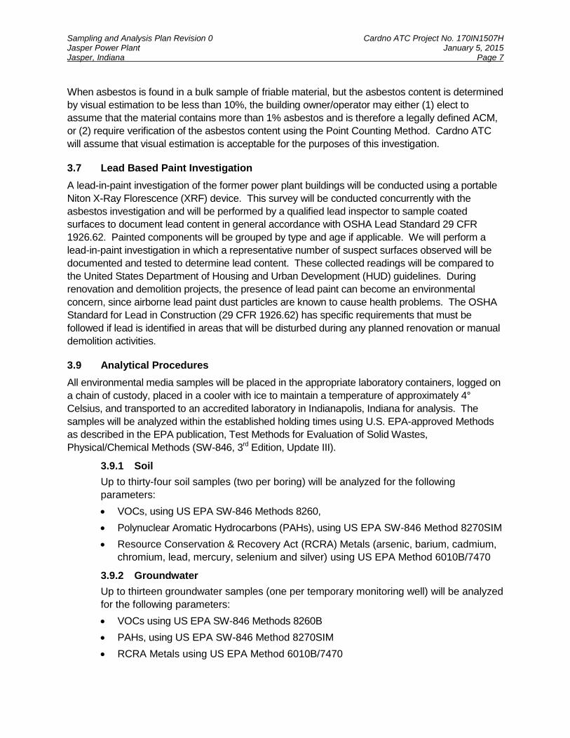
Seventeen soil borings will be advanced to a depth of approximately 30 feet below ground surface
(ft-bgs) or 5 ft below the groundwater table, whichever is shallower, with thirteen of the borings
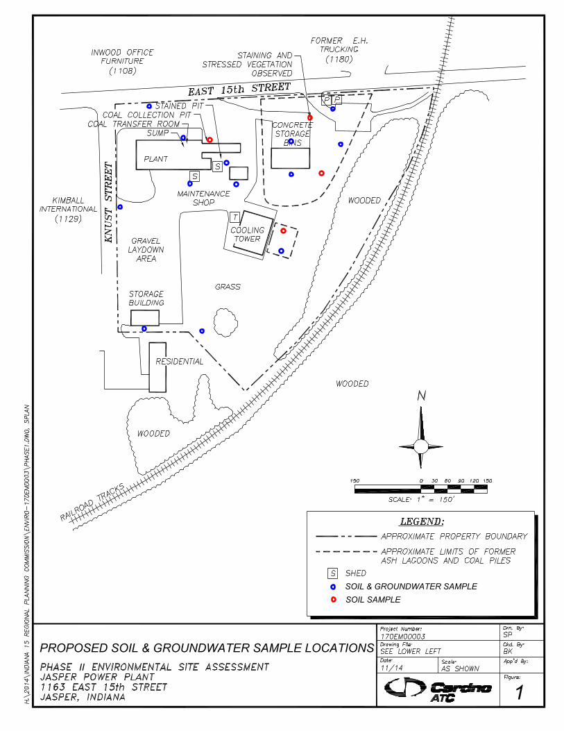
being completed as temporary monitoring wells. The proposed sampling locations are shown on
Figure 1. Although the general soil boring layout has been developed to focus on areas most
likely to have been adversely impacted by Site operations, the location of each soil boring will be
determined in the field based on access and field conditions. The proposed sample locations and
rationale are provided below:
Eight soil borings (5 temporary monitoring wells) will be advanced in the vicinity of the
former ash storage/lagoons.
Two soil borings (2 temporary monitoring wells) will be advanced along the north and west
Site boundaries to evaluate the potential migration of contaminated groundwater from
hydraulically upgradient properties.
Five soil borings (4 temporary monitoring wells) will be advanced in the vicinity of the main
building and maintenance shop.
Two soil borings (2 temporary monitoring wells) will be advanced along the southern
boundary to evaluate groundwater quality migrating from the Site.
3.5 Subsurface Investigation Procedures
Soil “grab” samples will be collected in accordance with IDEM RCG, as described in the Quality
Assurance Project Plan (QAPP) Revision 0, dated March 10, 2014, which was conditionally
approved by US EPA on June 6, 2014.
3.5.1 Soil Sampling
Each boring may initially be advanced using a stainless steel hand auger to a maximum
depth of approximately four ft-bgs to minimize the potential hazards associated with buried
utilities. The soil borings will then be advanced and soil samples collected continuously to
the desired depth using a track mounted Geoprobe® drill rig equipped with 5-foot long,
nominal 2-inch diameter Macro-core® samplers. The Macro-core samplers shall be
equipped with new plastic internal liners prior to collection of each sample.
Soil samples from a minimum of each 2-foot interval will be collected and sampled for
potential submittal to the laboratory for analysis. Each sample collected will be labeled and
placed in a cooler with ice for preservation following collection. A portion of the remaining
sample will then be placed into re-sealable plastic bag for field headspace screening. Each
soil sample will be inspected for physical evidence of contaminants such as staining, odors,
free product, etc. Soil headspace measurements will be collected for the emission of total
photo-ionizable vapors (TPVs) using a photo-ionization detector (PID) which measures
TPVs in parts per million (ppm). The inspection information, soil field descriptions, and
headspace emission measurements will be recorded on boring logs generated for each
boring location.
Two soil samples will be retained for laboratory analysis from each of the seventeen soil
borings. The samples retained for analysis will include the surface sample and the
Sampling and Analysis Plan Revision 0 Cardno ATC Project No. 170IN1507H Jasper Power Plant January 5, 2015 Jasper, Indiana Page 6
subsurface sample exhibiting the greatest potential for being impaired (i.e., highest TPV
reading, staining, odors, etc.) based on field screening and/or field inspection.
The samples retained for analysis will be containerized with minimal headspace in sample
containers provided by the laboratory, sealed using Teflon® lined caps, labeled with a
unique identification, placed in an ice-packed cooler and transported to Pace Analytical
Laboratory located in Indianapolis, Indiana using appropriate chain-of-custody protocol.
Soil samples to be analyzed for volatile organic compounds (VOCs) will be collected in
accordance with SW846 Method 5035 (Indiana Modified). Laboratory analyses will be
performed on a normal two-week turn around basis.
3.5.2 Groundwater Sampling
If groundwater is encountered and conditions permit, i.e. enough water is produced, Cardno
ATC will collect a groundwater sample from the thirteen temporary monitoring wells to be
installed. The location of the proposed wells is provided on Figure 1. Each temporary well
will be constructed of 1 inch diameter polyvinyl chloride (PVC) riser and a 10 ft factory
slotted screen. The groundwater samples will be collected using a low flow/low stress
sampling methodology. The water samples will be placed in appropriate sample containers,
labeled with a unique identification, placed in a cooler and transported to Pace Analytical
laboratory using the appropriate chain-of-custody controls. Laboratory analyses will be
performed on a normal two-week turn around basis. After the samples are collected, a
licensed water-well driller will return to the Site to properly abandon the temporary wells.
3.6 Asbestos Investigation
Conducting sampling to identify asbestos-containing materials will cost-effectively enable Indiana
15 to properly plan asbestos abatement activities, if warranted. The EPA’s National Emission
Standard for Hazardous Air Pollutants (NESHAP) standard for asbestos (40 CFR Part 61, Subpart
M) requires thorough inspections for the presence of both friable and non-friable ACMs in all
buildings to be demolished or renovated. Local, state and federal environmental agencies may
also require notification prior to any renovation or demolition activities in public or commercial
buildings, and this investigation will provide data required for in these notifications. Therefore, a
comprehensive asbestos investigation during which suspect materials observed throughout the
building will be documented and either sampled or assumed to contain asbestos. Category I non-
friable flooring and roofing material samples will not be collected as part of this survey unless
deemed by the inspector to be in friable condition, as these materials can be disposed of as regular
construction debris utilizing routine demolition activities, i.e. no cutting, abrading, sanding or
grinding. All samples will be collected by Cardno ATC building inspectors who are accredited by
the State of Indiana, as required by Indiana regulations.
During an asbestos investigation, the site will be inspected for the presence of surfacing materials
(i.e., plaster and textured paint), thermal system insulation (i.e., pipe coverings and pipe fitting
insulation) and miscellaneous materials (i.e., floor tile, wallboard and roofing materials) that may
contain more than 1 percent asbestos. All of the materials suspected of being ACMs are
categorized in homogeneous areas (HAs). Each HA consists of all observed materials found in
various locations in a building that are similar in color, appearance, texture and date of installation.
Sampling and Analysis Plan Revision 0 Cardno ATC Project No. 170IN1507H Jasper Power Plant January 5, 2015 Jasper, Indiana Page 7
When asbestos is found in a bulk sample of friable material, but the asbestos content is determined
by visual estimation to be less than 10%, the building owner/operator may either (1) elect to
assume that the material contains more than 1% asbestos and is therefore a legally defined ACM,
or (2) require verification of the asbestos content using the Point Counting Method. Cardno ATC
will assume that visual estimation is acceptable for the purposes of this investigation.
3.7 Lead Based Paint Investigation
A lead-in-paint investigation of the former power plant buildings will be conducted using a portable
Niton X-Ray Florescence (XRF) device. This survey will be conducted concurrently with the
asbestos investigation and will be performed by a qualified lead inspector to sample coated
surfaces to document lead content in general accordance with OSHA Lead Standard 29 CFR
1926.62. Painted components will be grouped by type and age if applicable. We will perform a
lead-in-paint investigation in which a representative number of suspect surfaces observed will be
documented and tested to determine lead content. These collected readings will be compared to
the United States Department of Housing and Urban Development (HUD) guidelines. During
renovation and demolition projects, the presence of lead paint can become an environmental
concern, since airborne lead paint dust particles are known to cause health problems. The OSHA
Standard for Lead in Construction (29 CFR 1926.62) has specific requirements that must be
followed if lead is identified in areas that will be disturbed during any planned renovation or manual
demolition activities.
3.9 Analytical Procedures
All environmental media samples will be placed in the appropriate laboratory containers, logged on
a chain of custody, placed in a cooler with ice to maintain a temperature of approximately 4°
Celsius, and transported to an accredited laboratory in Indianapolis, Indiana for analysis. The
samples will be analyzed within the established holding times using U.S. EPA-approved Methods
as described in the EPA publication, Test Methods for Evaluation of Solid Wastes,
Physical/Chemical Methods (SW-846, 3rd Edition, Update III).
3.9.1 Soil
Up to thirty-four soil samples (two per boring) will be analyzed for the following
parameters:
VOCs, using US EPA SW-846 Methods 8260,
Polynuclear Aromatic Hydrocarbons (PAHs), using US EPA SW-846 Method 8270SIM
Resource Conservation & Recovery Act (RCRA) Metals (arsenic, barium, cadmium,
chromium, lead, mercury, selenium and silver) using US EPA Method 6010B/7470
3.9.2 Groundwater
Up to thirteen groundwater samples (one per temporary monitoring well) will be analyzed
for the following parameters:
VOCs using US EPA SW-846 Methods 8260B
PAHs, using US EPA SW-846 Method 8270SIM
RCRA Metals using US EPA Method 6010B/7470
Sampling and Analysis Plan Revision 0 Cardno ATC Project No. 170IN1507H Jasper Power Plant January 5, 2015 Jasper, Indiana Page 8
3.9.3 Asbestos
Up to 50 suspected ACM bulk samples will be analyzed using US EPA Method
600/R-93/116. July, 1993.
In addition to the thirty-four discrete soil samples, thirteen groundwater samples described above,
two duplicate soil sample, one duplicate groundwater sample, three trip blanks, and three matrix
spike/matrix spike duplicate samples will be analyzed. A summary of the proposed sampling
program and applicable QA/QC samples is provided as Table 1.
The Method Detection Limits (MDLs) and Estimated Quantification Limits (EQLs) shall be low
enough to determine if the reported COC concentrations, if any, are in excess of the RCG
Screening Levels. Quality Assurance/Quality Control (QA/QC) shall be performed and submitted for
review in accordance with the RCG, and in accordance with the full data package criteria.
3.10 Decontamination Procedures
Sampling equipment and supplies (i.e. gloves, hand augers, etc.) will be dedicated to a specific
sample location, disposed of after use or decontaminated between sample collection. Sampling
personnel are to wear clean latex or nitrile gloves at any time they are handling equipment or
containers and will take all precautions to avoid contamination of equipment and supplies.
Geoprobe sampling equipment, which enters each borehole, will be cleaned prior to drilling. The
sampling equipment will also be cleaned between sample intervals using a solution of non-
phosphate detergent and rinsed in potable water. Parts or surfaces of the portable non-dedicated
equipment that come in contact with soil be decontaminated between sample collection points by
washing with a non-phosphate detergent wash, followed by a rinse in potable water.
3.12 Sampling Location Survey
The location of each soil boring will be recorded using a global positioning system, and the
elevation of each temporary well point will be surveyed to allow for correlation of groundwater
level data. The groundwater level data, collected prior to sample collection, will be utilized to
determine the apparent groundwater flow direction beneath the Site.
Sampling and Analysis Plan Revision 0 Cardno ATC Project No. 170IN1507H Jasper Power Plant January 5, 2015 Jasper, Indiana Page 9
4 Data Quality Objectives (DQOs)
This section discusses DQO’s for sampling and analysis of subsurface soil samples from the
area of interest identified during the IDEM’s site visits. The following types of data will be
generated in the course of this investigation:
Field observations and geologic and hydrogeologic conditions including soil
characteristics, and chemicals of concern (COC) indicators;
Field meter readings including those for measurement of water levels, basic water
chemistry, and TPV headspace screening;
Field records of onsite activities including well construction, sample collection, sample
handling, and other activities directly tied to the generation of data or the proper context
of data; and
Results of laboratory analysis of soil and groundwater samples.
The quality objective for these data types are discussed below and in further detail in the QAPP
Revision 0, dated March 10, 2014, which was conditionally approved by US EPA on June 6,
2014 for Indiana 15 Regional Planning Commission (US EPA Grant No. BF00E01209 0).
4.1 Field Observations and Documentation
Field documentation will be crucial to ensure the integrity of samples and the associated analytical
results. For these sampling tasks, documentation will include field logbooks, field data collection
forms, field meter calibration information, and chain of custody documentation. The quality of field
observations of geologic and hydrogeologic conditions relies heavily on the training and experience
of the personnel responsible for those activities. Criteria for performance are established through
standard operating procedures for the applicable activities presented in Section 3.0 (Sampling and
Analysis Plan). The quality objectives for these data will be to maintain adherence to the applicable
procedures and to maintain proper documentation.
4.2 Equipment Calibration
The quality of field meter readings relies on the proper calibration and operation of equipment.
Equipment used to gather, generate, or measure environmental data will be calibrated with
sufficient frequency and in such a manner that accuracy and reproducibility of results are
consistent with the manufacturer’s specifications.
At a minimum, each instrument will be calibrated in the laboratory or office prior to each sampling
event and operate in accordance with the manufacturer’s specifications. Equipment used during the
field sampling will be examined daily to certify that it is in operating conditions and calibrated
according to manufacturer’s instructions. If equipment malfunction is suspected and calibration
failure occurs, equipment will be removed from service and substitute equipment will be obtained.
Calibration activities will be recorded in the appropriate field forms or logbook(s).
Sampling and Analysis Plan Revision 0 Cardno ATC Project No. 170IN1507H Jasper Power Plant January 5, 2015 Jasper, Indiana Page 10
4.3 QA/QC Samples
To provide for a measurement of the precision and accuracy of the sampling event, the
following QA/QC samples will be submitted for analysis along with environmental media
samples.
4.3.1 Trip Blanks
1) Intent: Expose handling or transportation induced deterioration of the sample.
2) Method: Before the start of sampling, the laboratory will provide a blank TerraCore
Sampling Kit (1 vial with 25ml methanol and 2 vials with 5ml of DI water) to serve as a
trip blank for soil samples and a water sample trip blank for water samples) and .
These blanks will be sent from the laboratory to the site, and will be submitted for
analysis by the field sampling team. Trip Blanks will be analyzed for VOCs only.
3) Frequency: The trip blank for soil sampling will be one unused TerraCore sampling Kit
per bottle lot, and the trip blank for water samples will be one 40ml vial of laboratory
supplied DI water for each day of sampling and/or for each cooler used to store and
transport samples for VOC analysis.
4.3.2 Field Duplicates
1) Intent: Expose deficiencies in the sample collection and laboratory analysis that
influence sample precision.
2) Method: Field samples will be collected for a replicate analysis from selected
sampling locations. The sample will be collected by filling double the amount of
sample containers as called for in the sample plan. One set of samples will be
identified as the sample. The second set will be identified as a field duplicate.
3) Frequency: One field duplicate will be collected and submitted for every 20 samples
collected.
4.3.3 Matrix Spike/Matrix Spike Duplicates (MS/MSD) or Laboratory Duplicates
1) Intent: Evaluate laboratory precision, accuracy, representativeness, comparability and
completeness (PARCC) of the data parameters generated during this investigation.
2) Method: MS/MSD samples will be collected for replicate analysis from selected
sampling locations. The sample will be collected by filling triple the amount of sample
containers as called for in the sample plan. One set of samples will be identified as
the sample. The second and third sets will be identified as MS/MSD.
3) Frequency: One MS/MSD sample will be collected and submitted for every 20 samples
collected.
Sampling and Analysis Plan Revision 0 Cardno ATC Project No. 170IN1507H Jasper Power Plant January 5, 2015 Jasper, Indiana Page 11
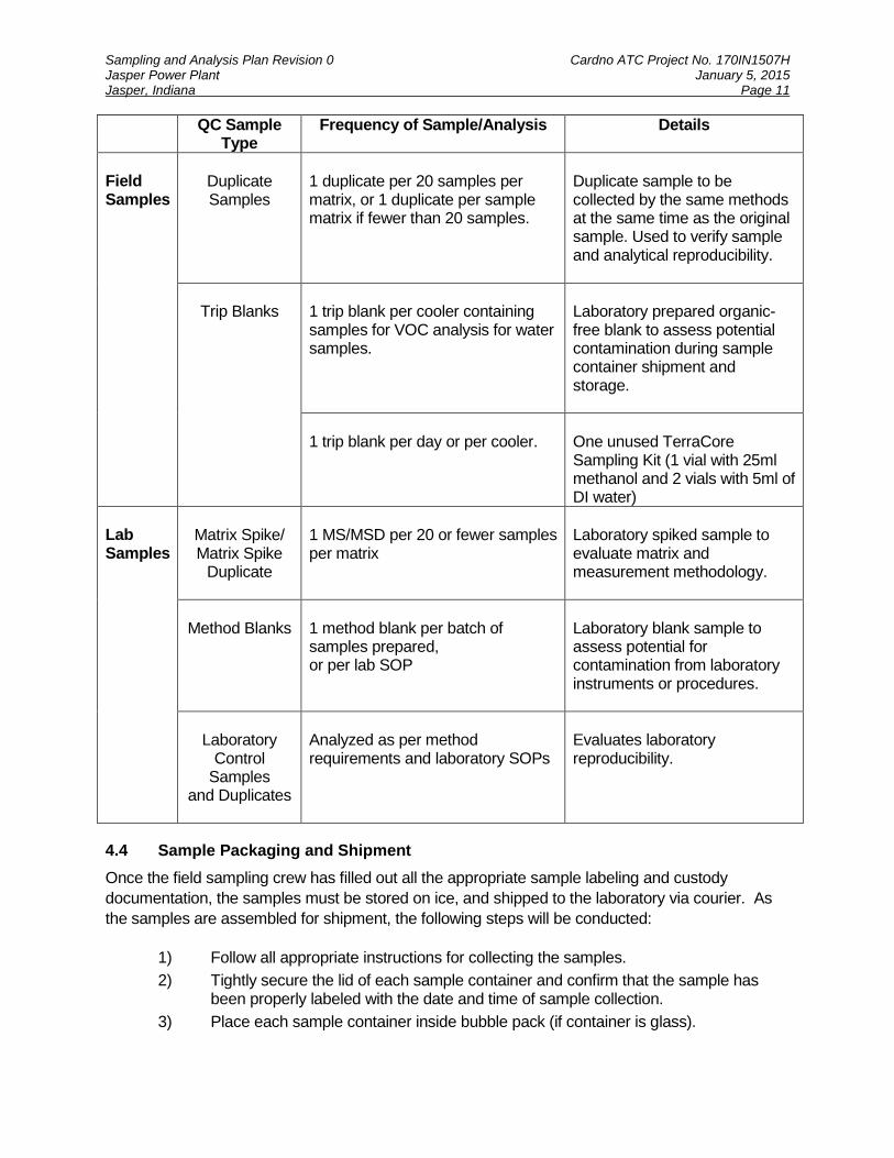
QC Sample Type
Frequency of Sample/Analysis Details
Field Samples
Duplicate Samples
1 duplicate per 20 samples per matrix, or 1 duplicate per sample matrix if fewer than 20 samples.
Duplicate sample to be collected by the same methods at the same time as the original sample. Used to verify sample and analytical reproducibility.
Trip Blanks
1 trip blank per cooler containing samples for VOC analysis for water samples.
Laboratory prepared organic-free blank to assess potential contamination during sample container shipment and storage.
1 trip blank per day or per cooler.
One unused TerraCore Sampling Kit (1 vial with 25ml methanol and 2 vials with 5ml of DI water)
Lab Samples
Matrix Spike/ Matrix Spike
Duplicate
1 MS/MSD per 20 or fewer samples per matrix
Laboratory spiked sample to evaluate matrix and measurement methodology.
Method Blanks
1 method blank per batch of samples prepared, or per lab SOP
Laboratory blank sample to assess potential for contamination from laboratory instruments or procedures.
Laboratory
Control Samples
and Duplicates
Analyzed as per method requirements and laboratory SOPs
Evaluates laboratory reproducibility.
4.4 Sample Packaging and Shipment
Once the field sampling crew has filled out all the appropriate sample labeling and custody
documentation, the samples must be stored on ice, and shipped to the laboratory via courier. As
the samples are assembled for shipment, the following steps will be conducted:
1) Follow all appropriate instructions for collecting the samples.
2) Tightly secure the lid of each sample container and confirm that the sample has been properly labeled with the date and time of sample collection.
3) Place each sample container inside bubble pack (if container is glass).
Sampling and Analysis Plan Revision 0 Cardno ATC Project No. 170IN1507H Jasper Power Plant January 5, 2015 Jasper, Indiana Page 12
4) Place the sample containers inside the sample cooler.
5) Place bubble wrap, or other suitable material that will maintain its integrity if it gets wet, between each sample container to take up any void space.
6) Add ice in the cooler containing the samples.
7) Place a chain-of-custody and any other instructions inside a resealable plastic bag and place the bag inside the cooler.
8) Close the cooler and secure closed with shipping tape by running the tape around both ends of the cooler at least two times.
9) Place one custody seal across the front of the cooler.
10) Place address label with both the "Shipped From" and "Ship To" addresses on the top of each cooler.
11) Notify the laboratory that it will be receiving the samples.
4.5 Chain of Custody Procedures
Possession of samples collected during field investigations must be traceable from the time the
samples are collected until they or their derived data are summarized used for data analysis,
interpretation, and site decision-making. Chain of custody procedures will be followed to maintain
sample accountability.
The custody form will document which individuals were in possession of the samples and when
custody was transferred from one individual to another. Any deviations from sampling protocol will
also be documented on the custody record. Additionally, the chain of custody form will double as a
request for analysis form. The custody form will specify the type and number of bottles shipped,
analysis to be performed and turnaround time requirements. The sample custody records will be
part of the final report.
Whenever the custody of samples is transferred, the individuals relinquishing and receiving the
sample will sign, date, and note the time on the record. Separate records will accompany each
sample package shipped to the laboratory. The original custody form will accompany the samples
and a copy will be retained by the sampling team.
When shipped by courier, the method of shipment and courier name will be noted in the remarks
column. For ground or air courier shipments to the laboratory, the sampling team will complete the
chain of custody, place it in the sampling cooler, and seal the cooler with shipping tape and a
custody seal. Samples will not be relinquished to the shipping firm; rather, the unbroken custody
seal will establish sample integrity during the time that the samples are in transit. Shipping return
receipts, freight bills, and bills of lading will be retained as part of the sample custody
documentation.
4.6 Laboratory Quality Assurance and Deliverables
The results of laboratory analyses are subject to the quality objectives of the Laboratory Quality
Assurance Manual (QAM), which is available on request from the laboratory that is used to
perform the analyses. The Laboratory QAM specifies methods for the maintenance and
calibration of equipment, handling of samples, execution of test procedures, and other activities
impacting the quality of the generated data.
Sampling and Analysis Plan Revision 0 Cardno ATC Project No. 170IN1507H Jasper Power Plant January 5, 2015 Jasper, Indiana Page 13
Analytical results will be validated internally by the laboratory, according to laboratory procedures.
The laboratory will assess the validity of sample results, along with duplicate, matrix spike/matrix
spike duplicate (MS/MSD), and blank sample results. Laboratory validation is performed according
to established internal quality control programs initiated by the laboratory.
Laboratory and field analytical results will be submitted in digital data files prepared in accordance
with IDEM digital data format guidance. Hardcopy analytical reports will also be submitted.
Standard, or Level II, laboratory QA/QC reporting will be provided with the original analytical
results. Level II laboratory data deliverables for performance monitoring samples will include:
Date and time of sample receipt;
Sample condition upon receipt;
Sample identification number;
Summary report of results (case narrative);
Sampling, preparation and analysis data;
Analytical and preparation methods used;
Sample, duplicate sample, and blank results;
Laboratory Control Sample results;
Matrix spike/matrix spike duplicate results;
Surrogate recoveries (for GC and GC/MS); and
Signed Chain-of-Custody sheets for all samples. In addition to the reporting elements listed above for Level II, Level III laboratory data deliverables
will include summaries of:
Instrument performance checks;
Initial calibration data;
Continuing calibration checks;
Methods;
Laboratory Control Samples;
MS/MSD results;
Surrogate recoveries;
Internal standards;
Retention times; and
GC analytical sequence In accordance with the RCG, if the laboratory results will be used for closure purposes, the final
laboratory report will include additional QA/QC documentation, including raw data. This laboratory
reporting level, referred to as Level IV, will accompany the analytical results submitted if requested.
The Level IV (Full Data Package) report will also include raw data for:
GC/MS tuning;
Continuing Calibration standards;
Initial Calibration curves;
Method blanks
Laboratory Control Samples;
Sampling and Analysis Plan Revision 0 Cardno ATC Project No. 170IN1507H Jasper Power Plant January 5, 2015 Jasper, Indiana Page 14
MS/MSD samples;
Sample Chromatograms and quantitative reports;
GC/MS Spectra;
Sample run logs; and
Extraction logs.
4.7 Analytical Results
The data will be used to evaluate if the soil and/or groundwater quality relative to the IDEM RCG
screening levels. If analytical results are found above the closure concentrations, additional soil
and groundwater assessment and/or remediation may be necessary.
When asbestos is found in a bulk sample of friable material, but the asbestos content is determined
by visual estimation to be less than 10%, the building owner/operator may either (1) elect to
assume that the material contains more than 1% asbestos and is therefore a legally defined ACM,
or (2) require verification of the asbestos content using the Point Counting Method. Cardno ATC
will assume that visual estimation is acceptable for the purposes of this investigation
Sampling and Analysis Plan Revision 0 Cardno ATC Project No. 170IN1507H Jasper Power Plant January 5, 2015 Jasper, Indiana Page 15
5 Data Quality Assessment
DQA involves assessing the effectiveness of the sample design, sampling procedure, and
laboratory analysis. DQA is used to ensure that the sampling and analytical quality are adequate
to meet the precision, accuracy, representativeness, comparability, and completeness (PARCC)
requirements established in the DQOs. DQA identifies the review process needed to support
project requirements and confirms that the field sampling QA/QC event, the field documentation,
and the QA/QC samples provide useable data. DQA also evaluates the final results of the site
investigation and compares them to the closure levels. Accordingly, DQA of field and laboratory
data collection will include the following:
Review of sampling design and data collection documentation;
Review of field measurement results;
Review of laboratory case narratives;
Review of field duplicate results;
Review of equipment blank results; and
Review of MS/MSD results and blank results.
Comparison of soil and groundwater concentrations to the IDEM RCG screening levels is part of the DQA process.

Figures
II
PROPOSED SOIL & GROUNDWATER SAMPLE LOCATIONS
1
SOIL & GROUNDWATER SAMPLE
SOIL SAMPLE

Tables
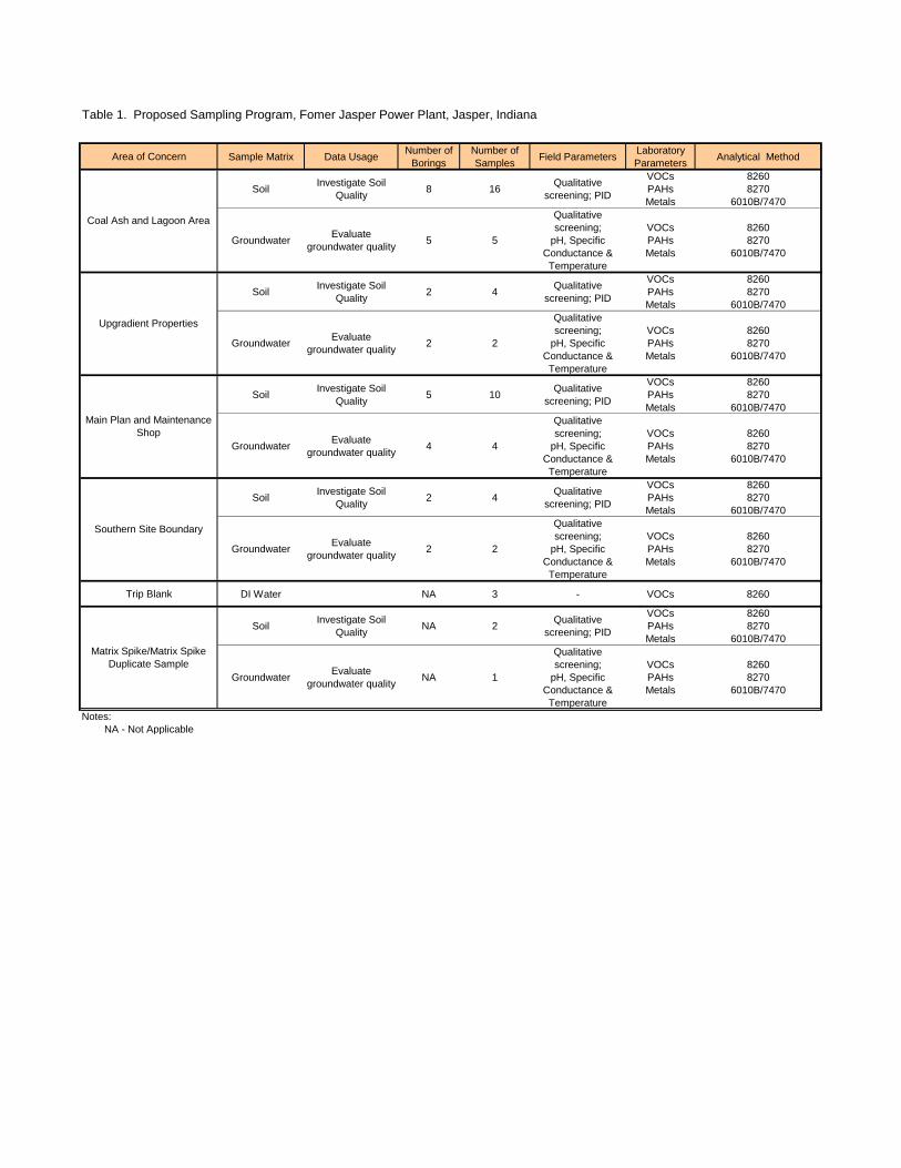
Table 1. Proposed Sampling Program, Fomer Jasper Power Plant, Jasper, Indiana
Area of Concern Sample Matrix Data UsageNumber of
Borings
Number of
SamplesField Parameters
Laboratory
ParametersAnalytical Method
SoilInvestigate Soil
Quality8 16
Qualitative
screening; PID
VOCs
PAHs
Metals
8260
8270
6010B/7470
GroundwaterEvaluate
groundwater quality5 5
Qualitative
screening;
pH, Specific
Conductance &
Temperature
VOCs
PAHs
Metals
8260
8270
6010B/7470
SoilInvestigate Soil
Quality2 4
Qualitative
screening; PID
VOCs
PAHs
Metals
8260
8270
6010B/7470
GroundwaterEvaluate
groundwater quality2 2
Qualitative
screening;
pH, Specific
Conductance &
Temperature
VOCs
PAHs
Metals
8260
8270
6010B/7470
SoilInvestigate Soil
Quality5 10
Qualitative
screening; PID
VOCs
PAHs
Metals
8260
8270
6010B/7470
GroundwaterEvaluate
groundwater quality4 4
Qualitative
screening;
pH, Specific
Conductance &
Temperature
VOCs
PAHs
Metals
8260
8270
6010B/7470
SoilInvestigate Soil
Quality2 4
Qualitative
screening; PID
VOCs
PAHs
Metals
8260
8270
6010B/7470
GroundwaterEvaluate
groundwater quality2 2
Qualitative
screening;
pH, Specific
Conductance &
Temperature
VOCs
PAHs
Metals
8260
8270
6010B/7470
Trip Blank DI Water NA 3 - VOCs 8260
SoilInvestigate Soil
QualityNA 2
Qualitative
screening; PID
VOCs
PAHs
Metals
8260
8270
6010B/7470
GroundwaterEvaluate
groundwater qualityNA 1
Qualitative
screening;
pH, Specific
Conductance &
Temperature
VOCs
PAHs
Metals
8260
8270
6010B/7470
Notes:
NA - Not Applicable
Matrix Spike/Matrix Spike
Duplicate Sample
Coal Ash and Lagoon Area
Upgradient Properties
Main Plan and Maintenance
Shop
Southern Site Boundary

Appendix A – Site Health and Safety Plan

HEALTH AND SAFETY PLAN
Prepared By: Cardno ATC
7988 Centerpoint Drive, Suite 100 Indianapolis, Indiana 46256
Prepared For:
INDIANA 15 REGIONAL PLANNING COMMISSION
JASPER POWER PLANT 1163 EAST 15TH STREET JASPER, INDIANA 47547
CARDNO ATC PROJECT NO. 170IN1507H
HASP Level III TC-1 Rev. – 01 (June 11, 2007)
CARDNO ATC HEALTH AND SAFETY PLAN (HASP)
REVIEW AND APPROVAL
CLIENT Indiana 15 Regional Planning Commission
PROJECT NUMBER: 170IN1507H
SITE NAME: Former Jasper Power Plant SITE LOCATION: Jasper, IN
PROJECT DESCRIPTION: Conduct subsurface investigation, including the collection of
near surface soil, subsurface soil, and groundwater samples.
PREPARED BY: Robert Walker Principal Geologist DATE: 1/5/15
Robert B. Walker 1/5/15 Project Manager
Signature Date
Reviewer’s Name
Signature Date
This Health and Safety Plan (Plan) has been written for the use of Cardno ATC. (ATC) and its employees. It may also be used as a guidance document by properly trained and experienced ATC subcontractors. However, ATC does not guarantee the health or safety of any person entering this Site. Due to the potential hazardous nature of this Site and the activity occurring thereon, it is not possible to discover, evaluate, and provide protection for all possible hazards which may be encountered. Strict adherence to the health and safety guidelines set forth herein will reduce, but not eliminate, the potential for injury at this Site. The health and safety guidelines in this Plan were prepared specifically for this Site and should not be used on any other Site without prior research by trained health and safety specialists. ATC claims no responsibility for use of this Plan by others. The Plan is written for the specific Site conditions, purposes, dates, and personnel specified and must be amended if these conditions change.
HASP Level III TC-2 Rev. – 01 (June 11, 2007)
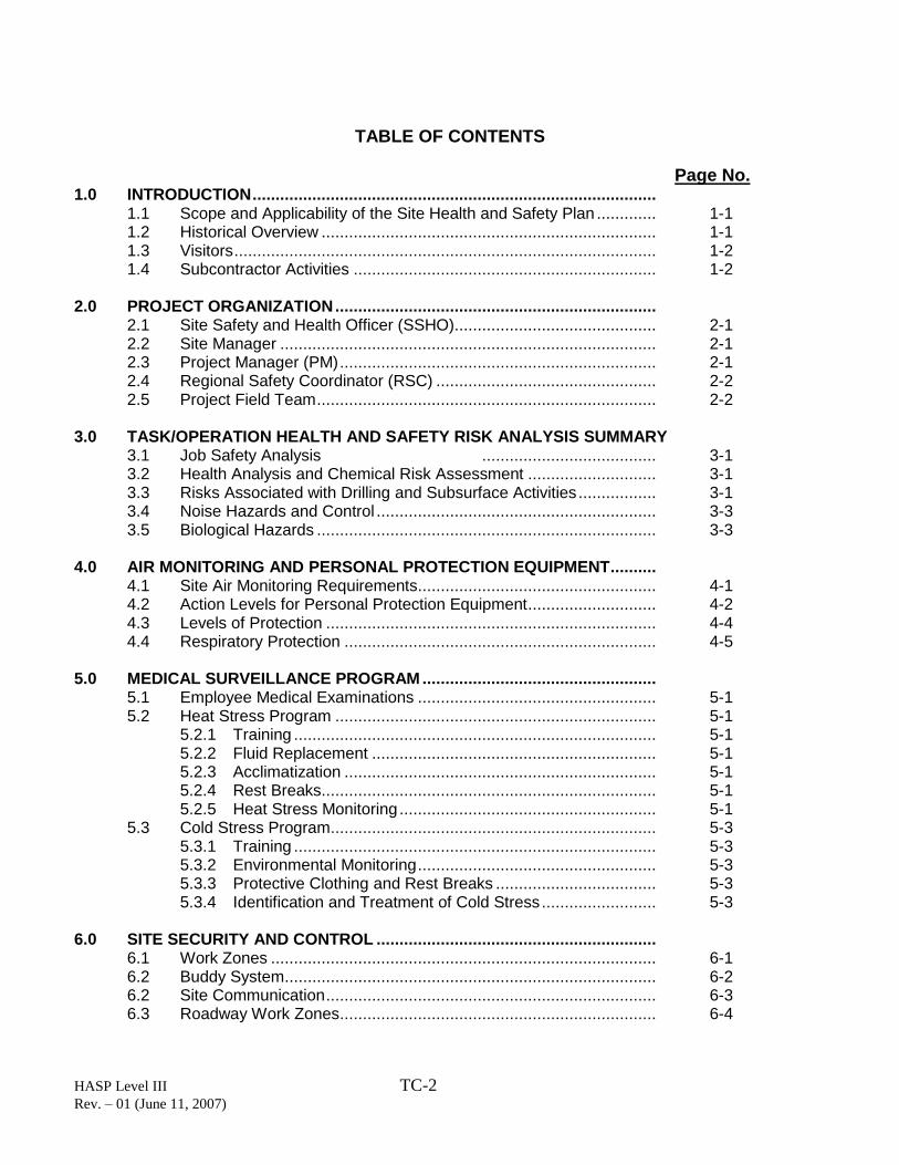
TABLE OF CONTENTS
Page No. 1.0 INTRODUCTION ........................................................................................
1.1 Scope and Applicability of the Site Health and Safety Plan ............. 1-1 1.2 Historical Overview ......................................................................... 1-1 1.3 Visitors ............................................................................................ 1-2 1.4 Subcontractor Activities .................................................................. 1-2
2.0 PROJECT ORGANIZATION ......................................................................
2.1 Site Safety and Health Officer (SSHO)............................................ 2-1 2.2 Site Manager .................................................................................. 2-1 2.3 Project Manager (PM) ..................................................................... 2-1 2.4 Regional Safety Coordinator (RSC) ................................................ 2-2 2.5 Project Field Team .......................................................................... 2-2
3.0 TASK/OPERATION HEALTH AND SAFETY RISK ANALYSIS SUMMARY
3.1 Job Safety Analysis ...................................... 3-1 3.2 Health Analysis and Chemical Risk Assessment ............................ 3-1 3.3 Risks Associated with Drilling and Subsurface Activities ................. 3-1 3.4 Noise Hazards and Control ............................................................. 3-3 3.5 Biological Hazards .......................................................................... 3-3
4.0 AIR MONITORING AND PERSONAL PROTECTION EQUIPMENT ..........
4.1 Site Air Monitoring Requirements .................................................... 4-1 4.2 Action Levels for Personal Protection Equipment ............................ 4-2 4.3 Levels of Protection ........................................................................ 4-4 4.4 Respiratory Protection .................................................................... 4-5
5.0 MEDICAL SURVEILLANCE PROGRAM ...................................................
5.1 Employee Medical Examinations .................................................... 5-1 5.2 Heat Stress Program ...................................................................... 5-1 5.2.1 Training ............................................................................... 5-1 5.2.2 Fluid Replacement .............................................................. 5-1 5.2.3 Acclimatization .................................................................... 5-1 5.2.4 Rest Breaks ......................................................................... 5-1 5.2.5 Heat Stress Monitoring ........................................................ 5-1 5.3 Cold Stress Program ....................................................................... 5-3 5.3.1 Training ............................................................................... 5-3 5.3.2 Environmental Monitoring .................................................... 5-3 5.3.3 Protective Clothing and Rest Breaks ................................... 5-3 5.3.4 Identification and Treatment of Cold Stress ......................... 5-3
6.0 SITE SECURITY AND CONTROL ............................................................. 6.1 Work Zones .................................................................................... 6-1 6.2 Buddy System ................................................................................. 6-2 6.2 Site Communication ........................................................................ 6-3 6.3 Roadway Work Zones ..................................................................... 6-4
HASP Level III TC-3 Rev. – 01 (June 11, 2007)
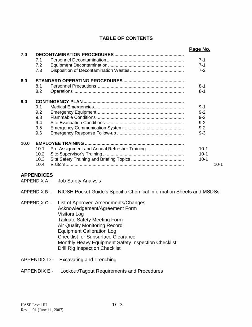
TABLE OF CONTENTS
Page No. 7.0 DECONTAMINATION PROCEDURES ......................................................
7.1 Personnel Decontamination ............................................................ 7-1 7.2 Equipment Decontamination ........................................................... 7-1 7.3 Disposition of Decontamination Wastes .......................................... 7-2
8.0 STANDARD OPERATING PROCEDURES ...............................................
8.1 Personnel Precautions .................................................................... 8-1 8.2 Operations ...................................................................................... 8-1
9.0 CONTINGENCY PLAN ..............................................................................
9.1 Medical Emergencies ...................................................................... 9-1 9.2 Emergency Equipment .................................................................... 9-2 9.3 Flammable Conditions .................................................................... 9-2 9.4 Site Evacuation Conditions ............................................................. 9-2 9.5 Emergency Communication System ............................................... 9-2 9.6 Emergency Response Follow-up .................................................... 9-3
10.0 EMPLOYEE TRAINING .............................................................................
10.1 Pre-Assignment and Annual Refresher Training ............................. 10-1 10.2 Site Supervisor’s Training ............................................................... 10-1 10.3 Site Safety Training and Briefing Topics ......................................... 10-1 10.4 Visitors ............................................................................................ 10-1
APPENDICES
APPENDIX A - Job Safety Analysis
APPENDIX B - NIOSH Pocket Guide’s Specific Chemical Information Sheets and MSDSs
APPENDIX C - List of Approved Amendments/Changes
Acknowledgement/Agreement Form Visitors Log Tailgate Safety Meeting Form Air Quality Monitoring Record Equipment Calibration Log
Checklist for Subsurface Clearance Monthly Heavy Equipment Safety Inspection Checklist Drill Rig Inspection Checklist APPENDIX D - Excavating and Trenching APPENDIX E - Lockout/Tagout Requirements and Procedures
HASP Level III TC-4 Rev. – 01 (June 11, 2007)
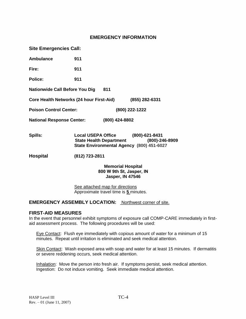
EMERGENCY INFORMATION Site Emergencies Call: Ambulance 911 Fire: 911 Police: 911 Nationwide Call Before You Dig 811 Core Health Networks (24 hour First-Aid) (855) 282-6331 Poison Control Center: (800) 222-1222 National Response Center: (800) 424-8802 Spills: Local USEPA Office (800)-621-8431 State Health Department (800)-246-8909 State Environmental Agency (800) 451-6027
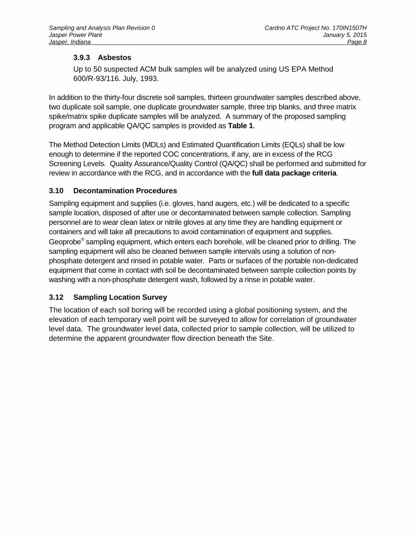
Hospital (812) 723-2811
Memorial Hospital
Jasper, IN 47546 See attached map for directions Approximate travel time is 5 minutes.
EMERGENCY ASSEMBLY LOCATION: Northwest corner of site.
FIRST-AID MEASURES In the event that personnel exhibit symptoms of exposure call COMP-CARE immediately in first-aid assessment process. The following procedures will be used:
Eye Contact: Flush eye immediately with copious amount of water for a minimum of 15 minutes. Repeat until irritation is eliminated and seek medical attention.
Skin Contact: Wash exposed area with soap and water for at least 15 minutes. If dermatitis or severe reddening occurs, seek medical attention. Inhalation: Move the person into fresh air. If symptoms persist, seek medical attention. Ingestion: Do not induce vomiting. Seek immediate medical attention.
HASP Level III TC-5 Rev. 01 – June 11, 2007
Important Numbers: Project Manager: …………………………….. Robert Walker 317-579-4014 Site Safety and Health Officer: ……………… Brian Kleeman 812-457-0043 Site Supervisor: ……………………………... Brian Kleeman 812-457-0043 Client Contact: ……………………………… Elliot Englert (812) 367-8455 Regional Safety Coordinator: ……………….. Nick Guidry (337) 262-7977 State Utility Locate Service: ………………... IUPPS 811 NOTE: For additional emergencies/important contacts, refer to your Cardno ATC Lifelines Card.

HASP Level III TC-6 Rev. 01 – June 11, 2007
EMERGENCY MEDICAL ROUTE TO HOSPITAL
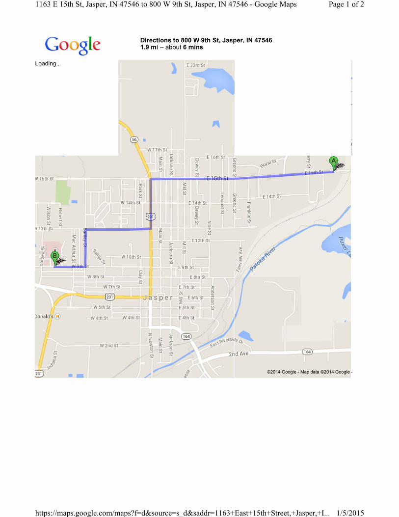
Directions to 800 W 9th St, Jasper, IN 475461.9 mi – about 6 mins
Loading...
©2014 Google - Map data ©2014 Google -
Page 1 of 21163 E 15th St, Jasper, IN 47546 to 800 W 9th St, Jasper, IN 47546 - Google Maps
1/5/2015https://maps.google.com/maps?f=d&source=s_d&saddr=1163+East+15th+Street,+Jasper,+I...
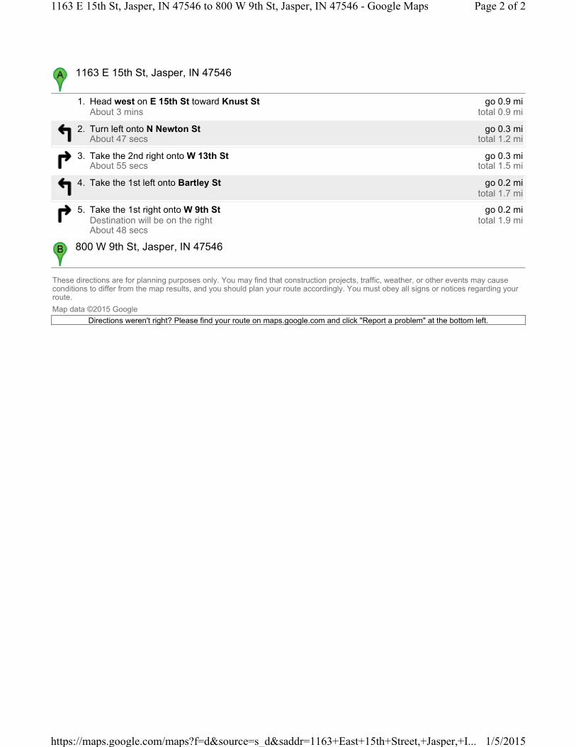
These directions are for planning purposes only. You may find that construction projects, traffic, weather, or other events may cause conditions to differ from the map results, and you should plan your route accordingly. You must obey all signs or notices regarding your route.
Map data ©2015 Google
Directions weren't right? Please find your route on maps.google.com and click "Report a problem" at the bottom left.
1. Head west on E 15th St toward Knust StAbout 3 mins
go 0.9 mitotal 0.9 mi
2. Turn left onto N Newton StAbout 47 secs
go 0.3 mitotal 1.2 mi
3. Take the 2nd right onto W 13th StAbout 55 secs
go 0.3 mitotal 1.5 mi
4. Take the 1st left onto Bartley St go 0.2 mitotal 1.7 mi
5. Take the 1st right onto W 9th StDestination will be on the rightAbout 48 secs
go 0.2 mitotal 1.9 mi
1163 E 15th St, Jasper, IN 47546
800 W 9th St, Jasper, IN 47546
Page 2 of 21163 E 15th St, Jasper, IN 47546 to 800 W 9th St, Jasper, IN 47546 - Google Maps
1/5/2015https://maps.google.com/maps?f=d&source=s_d&saddr=1163+East+15th+Street,+Jasper,+I...
HASP Level III
Rev. 01 – June 11, 2007 1-1
1.0 - INTRODUCTION
1.1 Scope and Applicability of the Site Health and Safety Plan
This Health and Safety Plan (HASP) has been prepared by Cardno ATC for the activities associated with the subsurface investigation at the Blackburn Auto Body, located in Tell City, Indiana (Site). The health and safety protocols established in this Plan are based on the Cardno ATC Employee Health and Safety Policy Manual, the Occupational Safety and Health Administration (OSHA) Regulations, past field experiences, specific Site conditions, and chemical hazards known or anticipated to be present from available Site data. The following Site Health and Safety Plan (HASP) is intended solely for use during the proposed activities described in the project documents and technical specifications. Specifications herein are subject to review and revision based on actual conditions encountered in the field during Site characterization activities. Such changes may be instituted by using the HASP List of Approved Amendments and/or Changes (see Appendix C). Before Site operations begin, all employees, including subcontractors for Cardno ATC covered by this plan, involved in these operations will have read and understood this HASP and all revisions. All Site personnel have the authority to “Stop Work” if unsafe conditions are present or discovered during Site activities. Before work begins, all affected workers will sign the Heath and Safety Plan Acknowledgment Form (see Appendix C). By signing this form, all individuals recognize the requirements of the HASP, known or suspected hazards, and will adhere to the protocols required for the project Site.
1.2 Historical Overview
The Phase I, dated December 9, 2014, identified the Site, located at 1163 East 15th Street, Jasper, Dubois County, Indiana as a former inactive coal-fired power plant situated in a relatively hilly area characterized by undeveloped, industrial, and residential land uses. The 8.46 acre parcel is improved with a main plant facility, located near the northwest corner of the Site and consists of several operations rooms, offices, maintenance areas, boiler areas, a turbine room, and coal transfer areas. Several stored containers, ASTs, and piping were also observed inside the plant. Various oils, wastewater treatment chemicals, and cleaning chemicals were stored in or around the plant. A maintenance shop is located southeast of the plant, which is used for storage and light maintenance activities on the Site. A cooling tower structure is also located southeast of the plant. A storage shed is located north of the cooling tower and is used to store wastewater treatment chemicals for past plant operations. When in operation, the cooling tower water was re-circulated and treated prior to re-use or discharge into the sanitary sewer system. A storage building containing equipment and supplies is located on the southwest corner of the Site. A mobile shed is located west of the maintenance shop and is used to store lawn equipment and fuel. Empty concrete storage bins were observed on the northeast part of the Site. The bins were once used to store coal during past plant operations. The bins are also used in the winter for salt and sand storage by the City. Staining and stressed vegetation was observed north of the storage bins. Concrete and asphalt pavement was observed on the north portion of the Site. A gravel lay-down lot is located south of the plant for storage of utility poles by the City. Grass and wooded areas make up the south and east portions of the Site. A Request for Eligibility was submitted to the US EPA on October 29, 2014 for review and approval. The US EPA approved the Eligibility Determination Request on November 4, 2014.
HASP Level III
Rev. 01 – June 15, 2007 1-2
The objective of the scope of work described in this SAP is to investigate the soil and groundwater quality at the in the vicinity of the RECs identified during the Phase I. Once the Site is characterized and the environmental issues are resolved, the Site may be redeveloped for commercial or industrial land use.
1.3 Visitors All visitors to the Site must be instructed about the hazards of the activities that Cardno ATC or its subcontractors are performing. All visitors must sign the Cardno ATC Visitors Log (see Appendix C).
1.4 Subcontractor Activities
All subcontractors used at the Site have been Pre-Approved in the Cardno ATC Subcontractor Prequalification System.