Embed Size (px)
Citation preview
5�• 1eo!F4-'0o04'11
CONTRACTOR REPORT
SAND85-71 11Unlimited ReleaseUC-70
Nevada Nuclear Waste Storage Investigations Project
Installation of Steel Linerin Blind Hole Study
Kenny Construction Company250 Northgate ParkwayWheeling, IL 60090
Prepared by Sandia National Laboratories Albuquerque, New Mexico 87185and Livermore, California 94550 for the United States Department of Energy
under Contract DE-AC04-76DP00789
Printed September 1987
"Prepared by Nevada Nuclear Waste Storage Investigations (NNWSI) Pro-ject participants as part of the Civilian Radioactive Waste ManagementProgram (CRWM). The NNWSI Project is managed by the Waste Manage-ment Project Office (WMPO) of the U. S. Department of Energy, NevadaOperations Office (DOE/NV). NNWSI Project work is sponsored by theOffice of Geologic Repositories (OGR) of the DOE Office of Civilian Radioac-tive Waste Management (OCRWM)."
Issued by Sandia National Laboratories, operated for the United StatesDepartment of Energy by Sandia Corporation.NOTICE: This report was prepared as an account of work sponsored by anagency of the United States Government. Neither the United States Govern-ment nor any agency thereof, nor any of their employees, nor any of theircontractors, subcontractors, or their employees, makes any warranty, expressor implied, or assumes any legal liability or responsibility for the accuracy,completeness, or usefulness of any information, apparatus, product, or pro-cess disclosed, or represents that its use would not infringe privately ownedrights. Reference herein to any specific commercial product, process, orservice by trade name, trademark, manufacturer, or otherwise, does notnecessarily constitute or imply its endorsement, recommendation, or favoringby the United States Government, any agency thereof or any of theircontractors or subcontractors. The views and opinions expressed herein donot necessarily state or reflect those of the United States Government, anyagency thereof or any of their contractors or subcontractors.
Printed in the United States of AmericaAvailable fromNational Technical Information ServiceU.S. Department of Commerce5285 Port Royal RoadSpringfield, VA 22161
NTIS price codesPrinted copy: A03Microfiche copy: A01
SAND85-7111Printed September 1987
DistributionCategory UC-70
INSTALLATION OF STEEL LINER IN BLIND HOLE STUDY
by
KENNY CONSTRUCTION COMPANY250 Northgate Parkway
Wheeling, Illinois 60090
for
SANDIA NATIONAL LABORATORIESP.O. Box 5800
Albuquerque, New Mexico 87185
UNDER SANDIA CONTRACT: 21-2633
Sandia Contract MonitorKenneth D. Young
Nuclear Waste EngineeringProjects Division
ABSTRACT
Lining of horizontally bored, waste-emplacement holes has beenstudied for possible use in underground nuclear wasterepositories. The principal objective of this study was todevelop and evaluate a technically feasible concept forinstalling a steel liner in a 37-in.-diameter borehole up to700 ft in length. This report reviews the history of jackingsuch lines in place, surveys existing equipment, reviews thecost estimate for this procedure, examines welding technologyfor the application, and concludes with a critical review ofthe construction risk.
iii/iv
CONTENTS
Page
1.0 INTRODUCTION 1
1.1 Background 11.2 Objectives and Approach 1
2.0 STEEL LINER INSTALLATION FEASIBILITY 3
2.1 Objectives 32.2 History of Comparable Projects 42.3 Market Survey of Existing Equipment 7
2.3.1 Equipment Manufacturers Contacted 72.3.2 Equipment Capabilities 9
2.4 Liner Installation Time and Cost Estimates 10
2.4.1 Typical Installation Sequence 102.4.2 Liner Installation Schedule 102.4.3 Basis for Liner Installation
Cost Estimate 122.4.4 Liner Installation Cost Estimate 122.4.5 Cost Summary 16
2.5 Personnel and Utility Requirements 17
2.6 Liner Welding System Feasibility 19
2.6.1 Welding Procedure 192.6.2 Weld Test 212.6.3 Welding Equipment and Costs 25
2.7 New Equipment Development, Tests, and Areasof Concern 26
2.7.1 New Equipment Development 262.7.2 Tests 292.7.3 Areas of Concern 29
3.0 CONCLUSIONS AND RECOMMENDATIONS 31
APPENDIX RIB/SEPDB DATA 33
v
FIGURES
Page
1 Jacking Pipe From a Rectangular Shaft 6
2 Jacking Steel Casing With Auger Excavation 8
3 Average Total Cost/Each 700-Ft Liner 18
4 450 "V" Bevel Butt Joint 20
5 Welding System Showing Wire Spooland Line Wire Feeder 22
6 Test Program Weld With No InternalProtrusions 23
7 Illustration of Final or Cap Weld,Average External Protrusion of 1/16 In. 24
8 Custom Liner Jacking System 27
9 Emplacement Equipment Within Haulageway 28
TABLE
Pacre
1 Liner Installation Schedule 11
vi
1.0 INTRODUCTION
1.1 Background
The work described in this report was performed for SandiaNational Laboratories (SNL) as part of the Nevada NuclearWaste Storage Investigations (NNWSI) project. SNL is oneof the principal organizations participating in the proj-ect, which is managed by the Waste Management ProjectOffice in the Department of Energy's Nevada OperationsOffice. The project is part of the Department of Energy'sprogram to develop a method to safely dispose of radio-active waste.
This report describes a system for installing a steelliner in a previously drilled, 37-in.-diameter, horizontalborehole up to 700 ft long. The report was prepared byKenny Construction Company for Sandia National Labo-ratories under Contract No. 21-2633. The system is one ofthose considered early in the development of the con-ceptual design for the emplacement of nuclear waste inlong, horizontal boreholes. The system is not thesimultaneous drill and line concept used in the SCP-CDRdesign for the NNWSi project; the simultaneous drill andline concept is an outgrowth of the evaluations presentedin this report.
1.2 Objectives and Approach
The principal objective of this study is to develop (andevaluate) a technically feasible concept for installing asteel liner in a 37-in.-diameter borehole up to 700 ft inlength. The evaluation includes consideration of thecosts and the availability of technology for use in theliner system. The approach taken in this report on asteel liner emplacement system consists of:
o developing a history of comparable projects constructedin the sizes that approximate the repository project;
o conducting a market survey of existing pipe jackingequipment and their capabilities;
o estimating liner installation time and cost estimates;
o estimating installation, manpower, and utilityrequirements including set-up, placing liner, transferto next station, etc.;
o evaluating and demonstrating a conceptual liner weldingsystem with welding time and cost estimates; and
o identifying new equipment development and proceduresthat should be addressed, recommended tests, or areasof concern.
1
The general approach used in determining the costs, choiceof equipment, and manpower was based on existingconstruction technology and comparable liner installationprojects.
2
2.0 STEEL LINER INSTALLATION FEASIBILITY
2.1 Obiectives
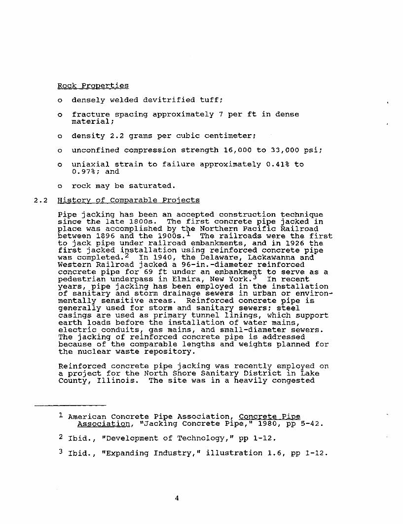
The principal objective of this study is to provide aconceptual report detailing a system to install a steelliner in a 37-in.-diameter blind hole up to 700 ft inlength. This system shall meet the following constraintsand criteria:
o The installation unit must be compact, it must becapable of operating in a 20-ft-wide by 10-ft-highhaulageway.
o The unit must comply with all mining codes andstandards.
o The unit shall be readily transportable from one holeto another with minimum setup and demobilization time.
o The liner emplacement hole direction can be from 800 to1000 from the axis of the drift and from -10° to 100elevation.
o The emplacement hole deviation will have no more than 6in. in 100 ft with no more than 12 in. accumulatedoffset.
o The unit shall be capable of being lowered down an 18-ft-diameter shaft, either intact or disassembled intomajor components.
o The emplacement hole will be considered stable with thepossibility of minimal rockfall within the hole.
o Liner shall be welded to provide a watertight joint.
o The blind end of the liner will be closed with a water-tight bulkhead.
o The liner will be assumed to be 0.5-in.-thick carbonsteel (1020), containing no internal or externalprotrusions.
Additionally, the environment and rock properties are
Underground Environment
Ambient Rock Temperature 350 C
Air Temperature 200 to 350 C
Relative Humidity Up to 100%
3
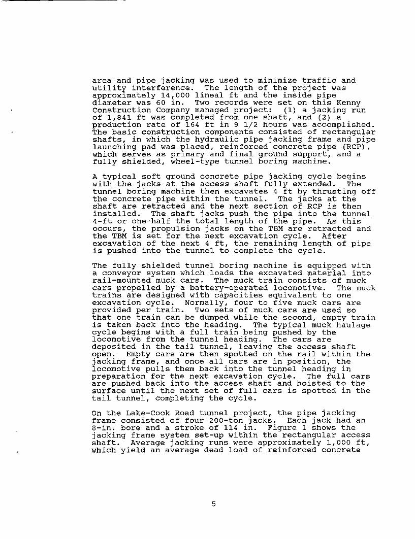
Rock Properties
o densely welded devitrified tuff;
o fracture spacing approximately 7 per ft in densematerial;
o density 2.2 grams per cubic centimeter;
o unconfined compression strength 16,000 to 33,000 psi;
o uniaxial strain to failure approximately 0.41% to0.97%; and
o rock may be saturated.
2.2 History of Comparable Projects
Pipe jacking has been an accepted construction techniquesince the late 1800s. The first concrete pipe jacked inplace was accomplished by the Northern Pacific Railroadbetween 1896 and the 1900s.1 The railroads were the firstto jack pipe under railroad embankments, and in 1926 thefirst jacked installation using reinforced concrete pipewas completed.2 In 1940, the Delaware, Lackawanna andWestern Railroad jacked a 96-in.-diameter reinforcedconcrete pipe for 69 ft under an embankment to serve as apedestrian underpass in Elmira, New York.3 In recentyears, pipe jacking has been employed in the installationof sanitary and storm drainage sewers in urban or environ-mentally sensitive areas. Reinforced concrete pipe isgenerally used for storm and sanitary sewers; steelcasings are used as primary tunnel linings, which supportearth loads before the installation of water mains,electric conduits, gas mains, and small-diameter sewers.The jacking of reinforced concrete pipe is addressedbecause of the comparable lengths and weights planned forthe nuclear waste repository.
Reinforced concrete pipe jacking was recently employed ona project for the North Shore Sanitary District in LakeCounty, Illinois. The site was in a heavily congested
1 American Concrete Pipe Association, Concrete PipeAssociation, "Jacking Concrete Pipe," 1980, pp 5-42.
2 Ibid., "Development of Technology," pp 1-12.
3 Ibid., "Expanding Industry," illustration 1.6, pp 1-12.
4
area and pipe jacking was used to minimize traffic andutility interference. The length of the project wasapproximately 14,000 lineal ft and the inside pipediameter was 60 in. Two records were set on this KennyConstruction Company managed project: (1) a jacking runof 1,841 ft was completed from one shaft, and (2) aproduction rate of 164 ft in 9 1/2 hours was accomplished.The basic construction components consisted of rectangularshafts, in which the hydraulic pipe jacking frame and pipelaunching pad was placed, reinforced concrete pipe (RCP),which serves as primary and final ground support, and afully shielded, wheel-type tunnel boring machine.
A typical soft ground concrete pipe jacking cycle beginswith the jacks at the access shaft fully extended. Thetunnel boring machine then excavates 4 ft by thrusting offthe concrete pipe within the tunnel. The jacks at theshaft are retracted and the next section of RCP is theninstalled. The shaft jacks push the pipe into the tunnel4-ft or one-half the total length of the pipe. As thisoccurs, the propulsion jacks on the TBM are retracted andthe TBM is set for the next excavation cycle. Afterexcavation of the next 4 ft, the remaining length of pipeis pushed into the tunnel to complete the cycle.
The fully shielded tunnel boring machine is equipped witha conveyor system which loads the excavated material intorail-mounted muck cars. The muck train consists of muckcars propelled by a battery-operated locomotive. The mucktrains are designed with capacities equivalent to oneexcavation cycle. Normally, four to five muck cars areprovided per train. Two sets of muck cars are used sothat one train can be dumped while the second, empty trainis taken back into the heading. The typical muck haulagecycle begins with a full train being pushed by thelocomotive from the tunnel heading. The cars aredeposited in the tail tunnel, leaving the access shaftopen. Empty cars are then spotted on the rail within thejacking frame, and once all cars are in position, thelocomotive pulls them back into the tunnel heading inpreparation for the next excavation cycle. The full carsare pushed back into the access shaft and hoisted to thesurface until the next set of full cars is spotted in thetail tunnel, completing the cycle.
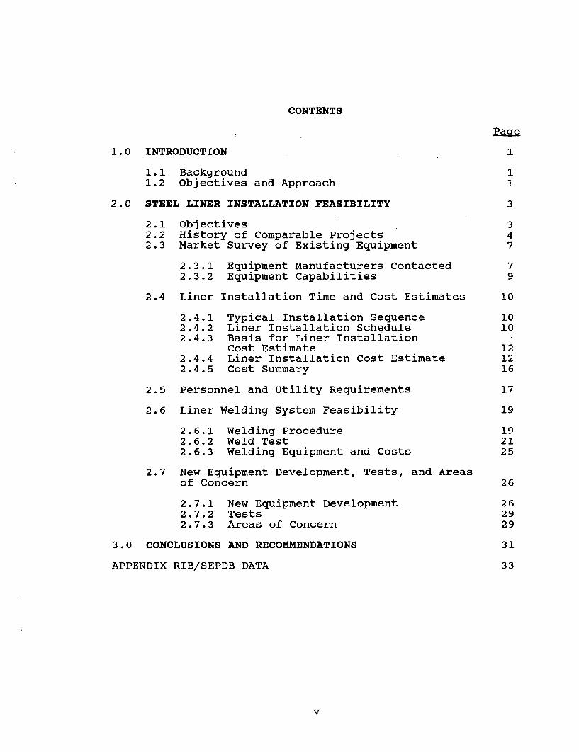
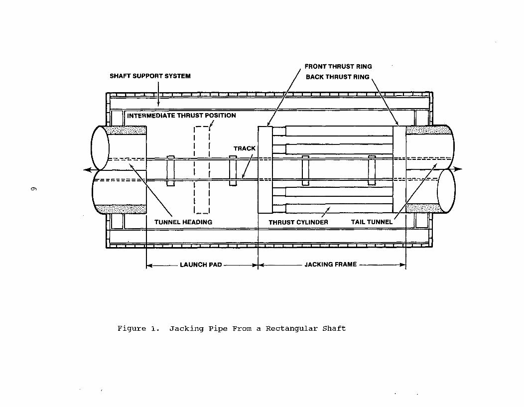
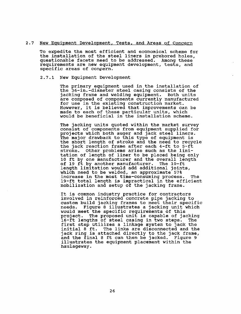
On the Lake-Cook Road tunnel project, the pipe jackingframe consisted of four 200-ton jacks. Each jack had an8-in. bore and a stroke of 114 in. Figure 1 shows thejacking frame system set-up within the rectangular accessshaft. Average jacking runs were approximately 1,000 ft,which yield an average dead load of reinforced concrete
5
SHAFT SUPPORT SYSTEMFRONT THRUST RING
BACK THRUST RING
I I mm
_ |INTERMEDIATE THRUST POSITION
II~~~T
L__~~~~~~~I_
TUNNEL HEADING
LAUNCH PAD
. . . ., . . . . . . . . . . HI 11 lai
. , ._ h _
_-
* .�
, _ _ ,
*ACK
/m-== = =1 -
/ Li -I
,___ ._ _ _ _ _ _ __ _,._ _ _ _ _ _ _ _ _ _ _ _,
_,-= =:===~=-
__
=, _
..
r
I I0 I-I . - ..... .
THRUST CYLINDER TAIL TUNNEL II IH=1~~~~~~~~~~~~~~~~~~~~~~~~~~~~~~~~~~~~~~~~~~~~~~~~~~~~-w i< JACKING FRAME -
Figure 1. Jacking Pipe From a Rectangular Shaft
pipe equal to 765 tons. To reduce friction loads and thusaxial loads on the RCP, the excavated diameter wasslightly larger than the outside diameter of the pipe.This annular space was filled with a bentonite slurrywhich acts as a lubricant and also supports the eartharound the pipe. The bentonite slurry was mixed in apumphouse at the surface and pumped to a manifold systemcarried within the pipe. The slurry was pumped into theannular space through nipples cast into the RCP by thepipe manufacturer.
Reinforced concrete pipe jacking, in association withtunnel boring machine excavation, has been successfullyemployed for diameters ranging from 42 in. through 120 in.For pipe sizes smaller than 42 in., hand excavation orcontinuous flight augers have been successful.
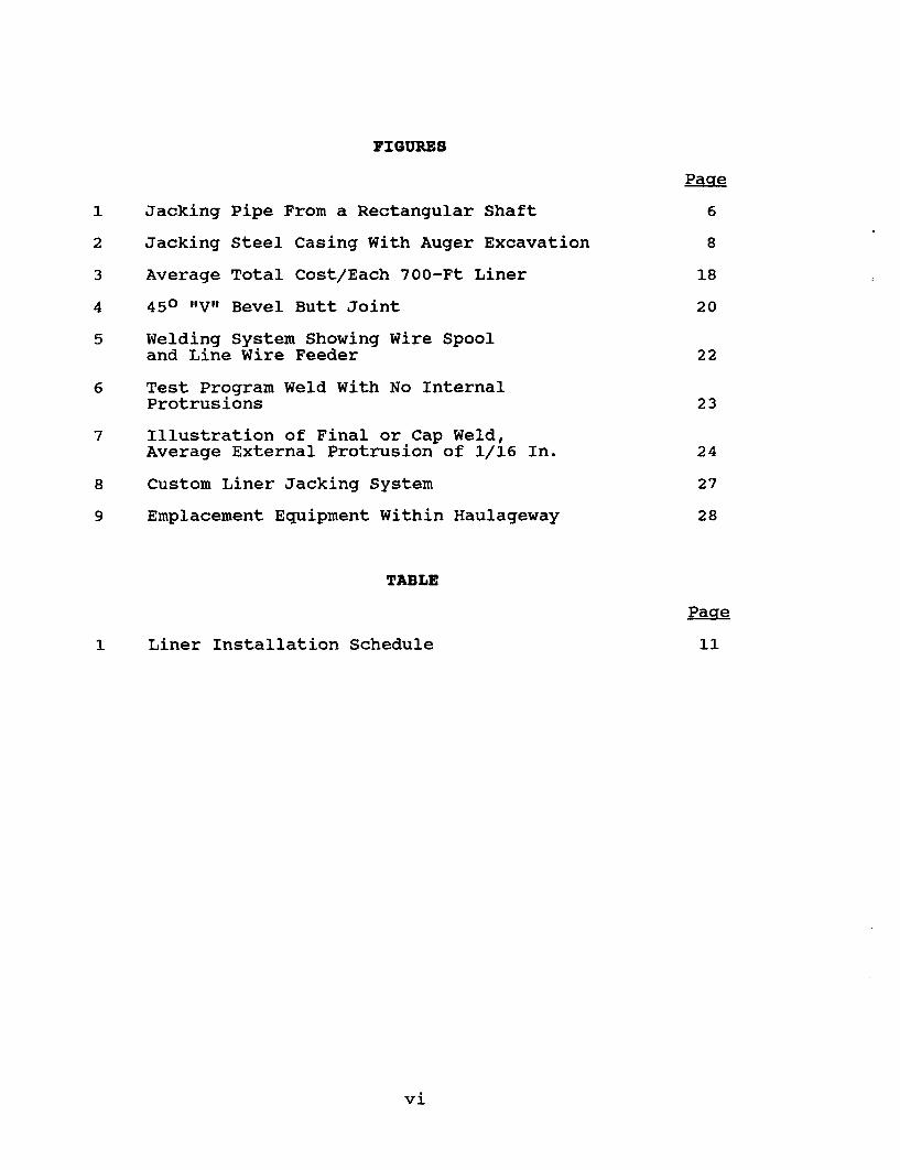
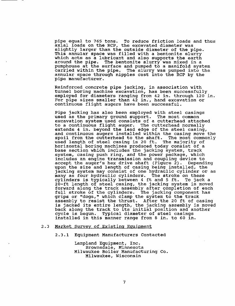
Pipe jacking has also been employed with steel casingsused as the primary ground support. The most commonexcavation system used consists of a cutterhead attachedto a continuous flight auger. The cutterhead normallyextends 4 in. beyond the lead edge of the steel casing,and continuous augers installed within the casing move thespoil from the cutterhead to the shaft. The most commonlyused length of steel casing is 20 ft. The majority ofhorizontal boring machines produced today consist of abase section which includes the jacking system, tracksystem, casing push ring, and the power package, whichincludes an engine transmission and coupling device toaccept the auger's hex drive shaft (Figure 2). Dependingupon the size and length of casing being installed, thejacking system may consist of one hydraulic cylinder or asmany as four hydraulic cylinders. The stroke on thesecylinders is typically between 4 ft and 5 ft. To jack a20-ft length of steel casing, the jacking system is movedforward along the track assembly after completion of eachfull stroke of the cylinders. The jacking component hasgrips or "dogs," which clamp the system to the trackassembly to resist the thrust. After the 20 ft of casingis jacked its entire length, the jacking assembly is movedback along the track to its initial position and anothercycle is begun. Typical diameter of steel casingsinstalled in this manner range from 8 in. to 60 in.
2.3 Market Survey of Existing Equipment
2.3.1 Equipment Manufacturers Contacted
Lampland Equipment, Inc.Brownsdale, Minnesota
Milwaukee Boiler Manufacturing Co.Milwaukee, Wisconsin
7
POWER PACKAGETRANSMISSION/ ENGINEPUSH RING & MUCK REMOVAL COMPARTMENT
CASINGCUT AWAY VIEW OF AUGER
ENGAGEDDOG SLOTCUTTER HEAD AUGER COUPLING
JACKING SYSTEM
Figure 2. Jacking Steel Casing With Auger Excavation
Carl W. Decker, Inc.Detroit, Michigan
American Augers, Inc.Detroit, Michigan
Calweld, Inc.Sante Fe Springs, California
Richmond Manufacturing Co.Ashland, Ohio
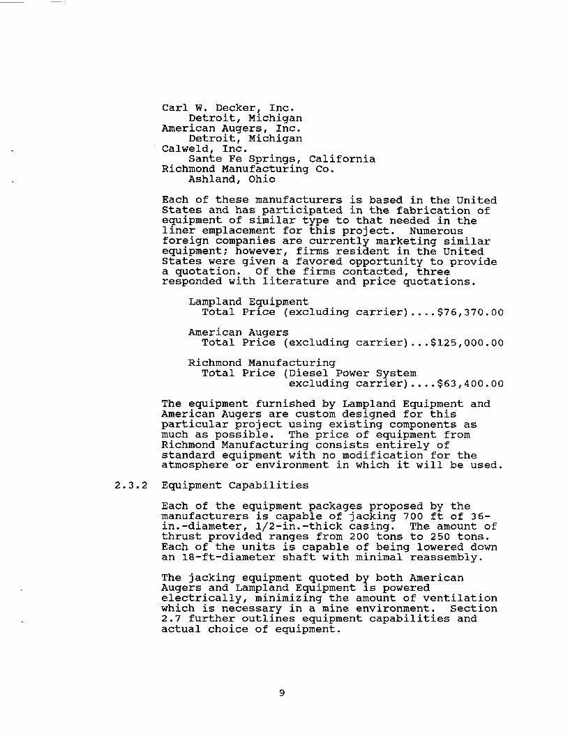
Each of these manufacturers is based in the UnitedStates and has participated in the fabrication ofequipment of similar type to that needed in theliner emplacement for this project. Numerousforeign companies are currently marketing similarequipment; however, firms resident in the UnitedStates were given a favored opportunity to providea quotation. Of the firms contacted, threeresponded with literature and price quotations.
Lampland EquipmentTotal Price (excluding carrier)....$76,370.00
American AugersTotal Price (excluding carrier).. .$125,000.00
Richmond ManufacturingTotal Price (Diesel Power System
excluding carrier)....$63,400.00
The equipment furnished by Lampland Equipment andAmerican Augers are custom designed for thisparticular project using existing components asmuch as possible. The price of equipment fromRichmond Manufacturing consists entirely ofstandard equipment with no modification for theatmosphere or environment in which it will be used.
2.3.2 Equipment Capabilities
Each of the equipment packages proposed by themanufacturers is capable of jacking 700 ft of 36-in.-diameter, l/2-in.-thick casing. The amount ofthrust provided ranges from 200 tons to 250 tons.Each of the units is capable of being lowered downan 18-ft-diameter shaft with minimal reassembly.
The jacking equipment quoted by both AmericanAugers and Lampland Equipment is poweredelectrically, minimizing the amount of ventilationwhich is necessary in a mine environment. Section2.7 further outlines equipment capabilities andactual choice of equipment.
9
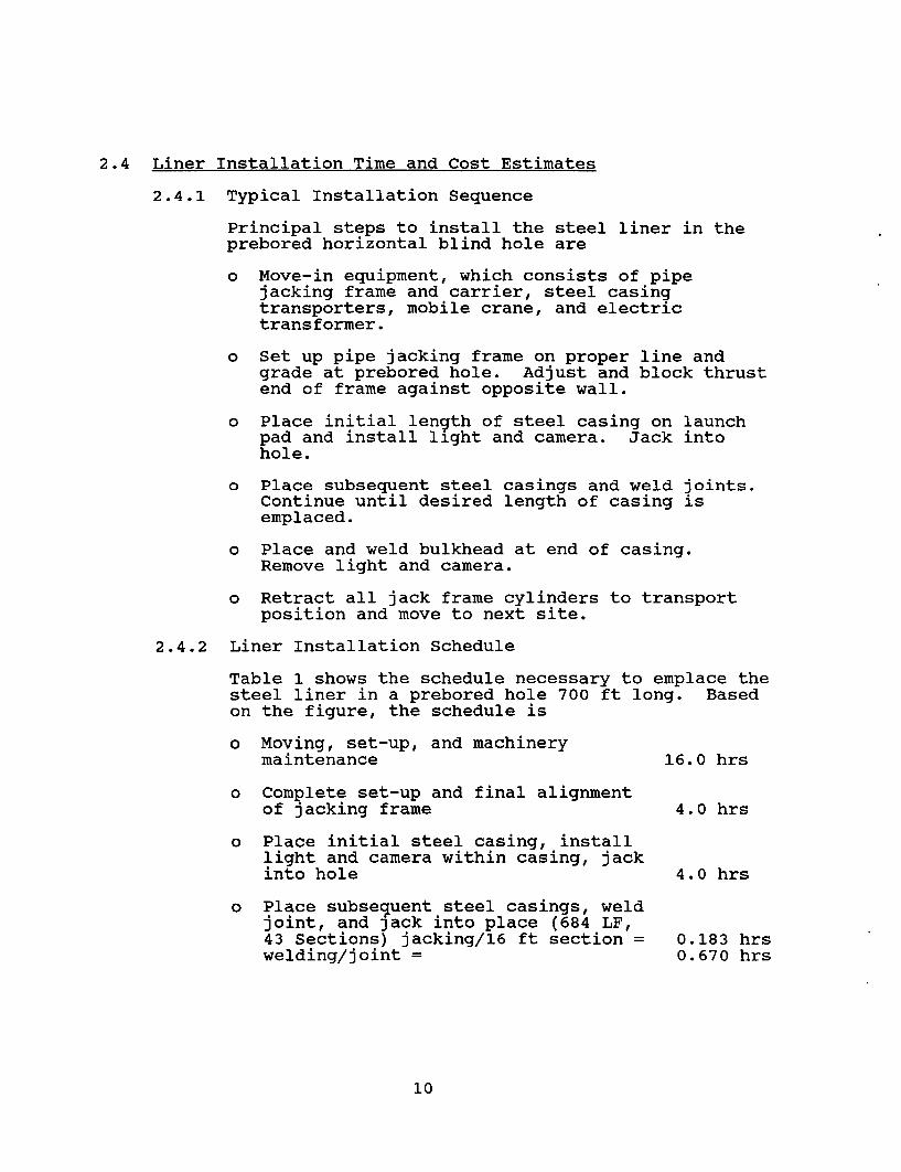
2.4 Liner Installation Time and Cost Estimates
2.4.1 Typical Installation Sequence
Principal steps to install the steel liner in theprebored horizontal blind hole are
o Move-in equipment, which consists of pipejacking frame and carrier, steel casingtransporters, mobile crane, and electrictransformer.
o Set up pipe jacking frame on proper line andgrade at prebored hole. Adjust and block thrustend of frame against opposite wall.
o Place initial length of steel casing on launchpad and install light and camera. Jack intohole.
o Place subsequent steel casings and weld joints.Continue until desired length of casing isemplaced.
o Place and weld bulkhead at end of casing.Remove light and camera.
o Retract all jack frame cylinders to transportposition and move to next site.
2.4.2 Liner Installation Schedule
Table 1 shows the schedule necessary to emplace thesteel liner in a prebored hole 700 ft long. Basedon the figure, the schedule is
o Moving, set-up, and machinerymaintenance 16.0 hrs
o Complete set-up and final alignmentof jacking frame 4.0 hrs
o Place initial steel casing, installlight and camera within casing, jackinto hole 4.0 hrs
o Place subsequent steel casings, weldjoint, and jack into place (684 LF,43 Sections) jacking/16 ft section = 0.183 hrswelding/joint = 0.670 hrs
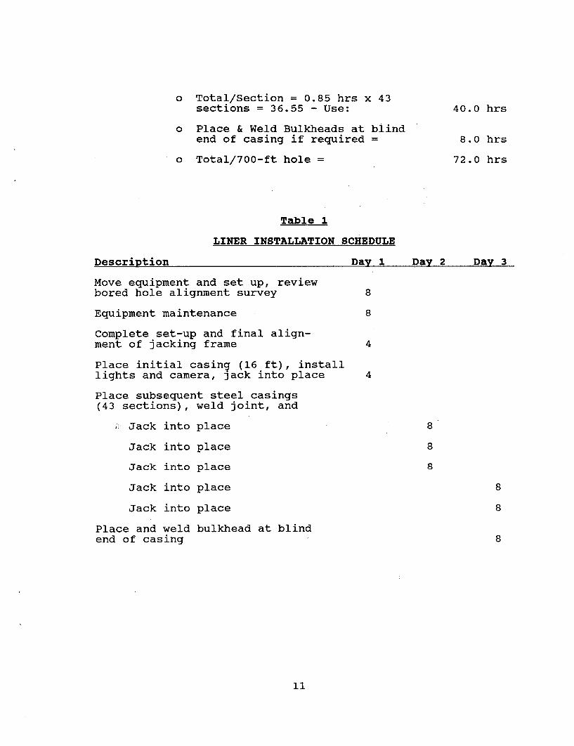
o Total/Section = 0.85 hrs x 43sections = 36.55 - Use:
o Place & Weld Bulkheads at blindend of casing if required =
o Total/700-ft hole =
40.0 hrs
8.0 hrs
72.0 hrs
Table 1
LINER INSTALLATION SCHEDULE
Description
Move equipment and set up, reviewbored hole alignment survey
Equipment maintenance
Complete set-up and final align-ment of jacking frame
Place initial casing (16 ft), installlights and camera, jack into place
Place subsequent steel casings(43 sections), weld joint, and
Jack into place
Jack into place
Jack into place
Jack into place
Jack into place
Place and weld bulkhead at blindend of casing
Day 1 nu 9 nwu 2Y ^ Calf J
_ _ J _ _ _ s _ _ _ J _
8
8
4
4
8
8
8
8
8
8
11
2.4.3 Basis for Liner Installation Cost Estimate
As a basis for the cost estimate for a demonstra-tion of this technology, the Nuclear Test Site,Nevada, was chosen as the generic site. All laborrates, material prices, and equipment freight ratescoincide with existing agreements and rates cur-rently established for this area. It has beenassumed that a minimum of six holes, approximately700 ft long, will have casings installed. Thiswill minimize the effects of a typical "learningcurve."
Services and equipment necessary, but not includedare
o electrical, water, compressed air, andventilation from surface to liner installationsites;
o unloading of equipment and materials at site;
o lowering and assembly of equipment at bottom ofshaft; and
o shaft service for men and materials duringinstallation of liners.
2.4.4 Liner Installation Cost Estimate
The cost estimate is broken into five sections,which include labor cost, materials cost, equipmentoperations expense, supervision and overhead costs,and equipment purchase costs.
(1) Total Labor Cost
The typical crew for the complete installationprocess consists of
Heavy-Duty Repairman/Welder 2 people
Jack Frame Operator 1 person
Mine Vehicle/Boom Operator 1 person
Laborer 1 personTOTAL 5 people
Nine shifts are needed to install 700 ft ofsteel casing in prebored hole, Table 1. Numberof Manhours: 9 shifts x 8 hours/shift x 5people = 360 manhours.
12
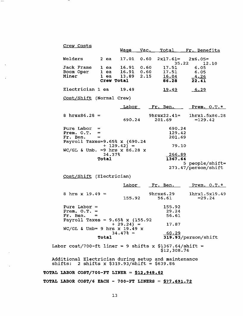
Crew CostsWare Vac. Total Fr. Benefitsq
Welders
Jack FrameBoom OperMiner
2 ea 17.01 0.60 2x17.61= 2x6.05=35.22 12.10
1 ea 16.91 0.60 17.51 6.051 ea 16.91 0.60 17.51 6.051 ea 13.89 2.15 16.04 4.26Crew Total 86.28 22.41
Electrician 1 ea 19.49 19.49 6.29
Cost/Shift (Normal Crew)
Labor Fr. Ben. Prem. 0.T.*
8 hrsx86.28 = 9hrsx22.41=201.69
lhrxl.5x86.28=129.42690.24
Pure Labor =Prem. O.T. =Fr. Ben. =Payroll Taxes=9.65% x (690.24
+ 129.42) =WC/GL & Umb. =9 hrs x 86.28 x
34.37%Total
690.24129.42201.69
79. 10
266.891367 .64
5 people/shift=273.47/person/shift
Cost/Shift (Electrician)
Labor Fr. Ben. Prem. 0.T.*
8 hrs x 19.49 = 9hrsx6.2956.61
lhrxl.5xl9.49=29.24155.92
Pure Labor =Prem. O.T. =Fr. Ben. =Payroll Taxes = 9.65% x (155.92
+ 29.24) =WC/GL & Umb= 9 hrs x 19.49 x
34.47% =Total
155.9229.2456.61
17.87
60.29319.93/person/shift
Labor cost/700-ft liner = 9 shifts x $1367.64/shift =$12,308.76
Additional Electrician during setup and maintenanceshifts: 2 shifts x $319.93/shift = $639.86
TOTAL LABOR COST/700-FT LINER = $12,948.62
TOTAL LABOR COST/6 EACH - 700-FT LINERS = $77,691.72
13
*NOTE: Premium overtime included at 1 hr shift tocompensate for travel to and from miner in-stallation area.
(2) Total Materials Cost
Steel Casing (36-in. outside diameter, 1/2-in. wallthickness, carbon steel (1020), prebeveled ends,F.O.B. jobsite)
700 ft x $61.61/LF = $43,127.00
Blind End Bulkhead Plate (1/2-in.thick, 1020 carbon steel)
1 ea. x $36.03/ea =
Welding Wire (Dual Shield II-70,.045 diameter)
$ 36.03
700 LF/16 ft per joint = 44 joints44 welded joints x $9.89/joint +10% waste = $ 478.68
Weld Shield Gas (75/25; Argon/Carbon-dioxide
44 welded joints x $3.00/joint +20% Waste =
Total Materials Cost/700-ft liner =
Total Material Cost/6 each -700-ft liners =
$ 158.40
$43,800.11
$262,800.66
(3) Total Equipment Operations Expense
Jacking Frame and Carrier
Parts and Hydraulic Oil 30% ofShift Time - 30% x 6 shifts x8 hrs/shift x $7.24/hr =
3-Ton Low Profile Diesel PoweredTruck with Scrubber and PTOHydraulic Boom
$ 104.26
9 shifts x 8 hrs/shift x$5.35/hr = $ 385.20
14
-
Liner Transport Wagons (2 ea)
6 shifts x 8 hrs/shift x 50%x 2 ea x $1.15/hr = $ 55.20
Welders & Wire Feeds (2 Sets)
7 shifts x 8 hrs/shift x 80%x 2 sets x $1.07/hr =
Total Equipment Operations Expenseper 700-ft liner =
Total Equipment operationsExpense/6 Each - 700-ft liners =
$ 95.87
$ 640.53
$3,843.18
NOTE: This amount does not include any expense forelectrical, ventilation, or other utilities supplied bythe mine site.
(4) Supervision and Overhead
Based on six installations - four-week duration
Supervision (incl. insurance,
Project ManagerSuperintendent (swing shift)Superintendent (graveyardshift)Project EngineerSafety EngineerTimekeeper/Clerk
Subtotal
tax, and benefits)
4 wk x 1933 = $77324 wk x 1610 = 6440
4444
wkwkwkwk
xxxx
1610 = 64401288 = 5152966 = 3864805 = 3220
$32,848
General Accounts
Office SuppliesEngineering SuppliesLegal & AuditSafety & First AidTelephoneSmall Tools (Direct Pure
Labor x 10%)Subsistence - 5 people x
travel-home office - dx 2 trips x 1000/trip
Moving Expenses -Safety TrainingFederal Express
1 mo1lmoLump1 mo1 mo
1 mo2 people
5 men1 mo1 Mo
x 600 =x 300 =Sum =x 600 =x 1000 =
$ 600300
10, 000600
1, 000
= 3,914x 750 = 3,750
= 4,000x 2000 = 10,000x 400 = 400x 320 = 320
$34,884Subtotal
15
Insurance
Car Insurance 4 cars x $50/month = $ 200$ 200Subtotal
Equipment
Fuel, Oil, and Grease - Cars -4 ea x $450/mo x 1 mo =
Subtotal
Plant Installation
$ 1.800$ 1,800
Office Trailer - Install & Remove =Subtotal
$ 8,000$ 8,000
TOTAL SUPERVISION AND OVER-HEAD/6 EA-700-FT LINERS = $77,732
(5) Equipment Purchase Costs
Liner Welding System (Subsection 2.6.3)Jacking System (Subsection 2.73 Ton Low Profile Diesel Powered Truck
with Scrubber & Hydraulic Boom2-Axle Transport Wagons-3 ea @ $2500Video Camera and MonitorLightingVentilation Equipment for Welding Bulk-
head of Blind End of Liner
TOTAL EQUIPMENTPURCHASE COST =
$11,327.90119,700.00
52,000.007,500. 001,400.002,650.00
2,500.00
$197,077.90
2.4.5 Cost Summary
The total cost based on a pilot program of six each700-ft liners, excluding home office G&A, and feeis
o Labor Cost = $ 77,691.22
o Materials Cost = 262,800.66
o Equipment Operations Expense - 3,843.18
o Supervision = 77,732.00
o Equipment = 197,077.90
TOTAL COST = $619,144.96
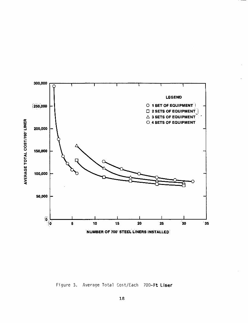
16
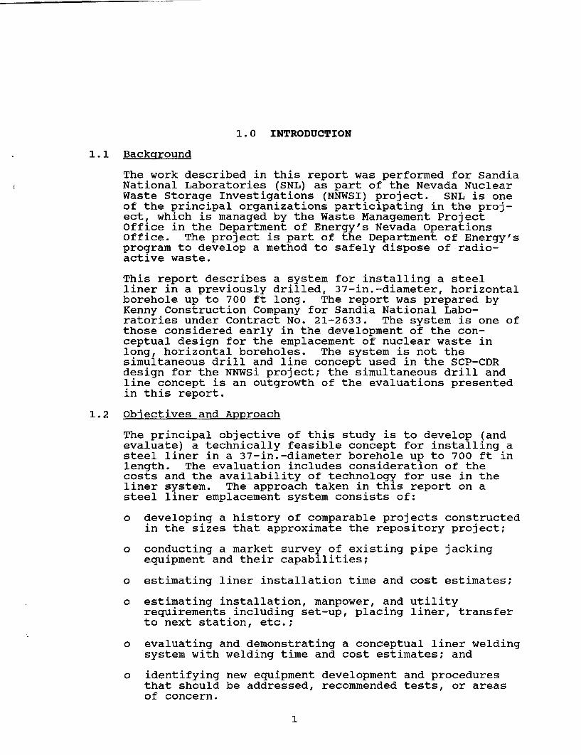
The total cost per each 700-ft liner = $103,190.83The following Figure 3 illustrates the average totalcost/each 700-ft liner installed for various numbers ofliners and differing amounts of equipment.
2.5 Personnel and Utility Requirements
To expedite the installation of the six, 700-ft long steelcasings, using one set of equipment, the followingpersonnel and utilities will be required.
The crew necessary to move the equipment from liner siteto liner site, to set up the system, to maintain theequipment, and to install the steel liners consists of
Heavy Duty Repairman/Welder - 2 peopleJack Frame Operator - 1 personMine Vehicle/Boom Operator - 1 personLaborer - 1 person
Total - 5 people
Electrician (setup &maintenance) - 1 person
Working three shifts per day yields a work force of 15people performing installation with two electriciansneeded during maintenance and setup. In addition, asupervisory staff of six is indicated. Additionalsupport, not included in the estimate, would consist of ashaft hoist operator, man hoist operator, and two toplaborers to service the underground crew duringinstallation and setup. Working three shifts per dayyields 12 support personnel. This crew could also be usedto service the drilling operations.
Utility requirements include ventilation and electricalpower. The ventilation is determined as the greatestvalue of
A. 200 CFM x No. of People + Diesel Machine RequirementsNo. of Men = 5 Standard Crew + 2 Supervisory Personnel
+ 3 inspectors = 10 people
Mine vehicle requirements = 3,000 CFM
Total CFM = 10 people x 200 CFM/person + 3,000 CFM =5,000 CFM
B. To provide enough ventilation, especially duringwelding procedures, a velocity of 30 FPM is required.Therefore, the CFM needed is equal to 30 ft per minutex the cross-sectional area of the haulageway, 10 ft x20 ft.
17
Imlz3
aP-I-Uc0
-i
0I.-
4LU
4
300,000 7
f 250,000
200,000 -
150,000
100,000
50,000
10! 0 5 10 15 20 25 30 35
NUMBER OF 700' STEEL LINERS INSTALLED
Figure 3. Average Total Cost/Each 700-Ft Liner
18
Total CFM = 30 FPM x 200 square feet= 6,000 CFM
Using the greatest value yields, a ventilationrequirement of at least 6,000 cubic feet per minute.
The electrical power needed to service the equipmentis 400 amperes, 480 volts.
2.6 Liner Welding System Feasibility
2.6.1 Welding Procedure
The task is to develop a liner welding system forjointing sections of 36-in. diameter, 1/2-in. wall,carbon steel (1020). The welded joint shall haveno internal or external protrusions and must alsobe watertight. Areas of concern include the actualjoint design, the welding procedure, and the weldmaterials.
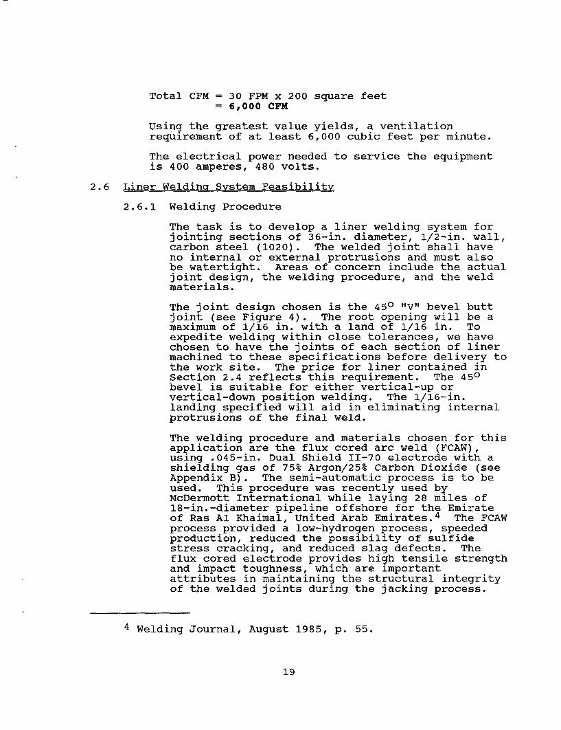
The joint design chosen is the 450 "V" bevel buttjoint (see Figure 4). The root opening will be amaximum of 1/16 in. with a land of 1/16 in. Toexpedite welding within close tolerances, we havechosen to have the joints of each section of linermachined to these specifications before delivery tothe work site. The price for liner contained inSection 2.4 reflects this requirement. The 450bevel is suitable for either vertical-up orvertical-down position welding. The 1/16-in.landing specified will aid in eliminating internalprotrusions of the final weld.
The welding procedure and materials chosen for thisapplication are the flux cored arc weld (FCAW),using .045-in. Dual Shield II-70 electrode with ashielding gas of 75% Argon/25% Carbon Dioxide (seeAppendix B). The semi-automatic process is to beused. This procedure was recently used byMcDermott International while laying 28 miles of18-in.-diameter pipeline offshore for the Emirateof Ras Al Khaimal, United Arab Emirates.4 The FCAWprocess provided a low-hydrogen process, speededproduction, reduced the possibility of sulfidestress cracking, and reduced slag defects. Theflux cored electrode provides high tensile strengthand impact toughness, which are importantattributes in maintaining the structural integrityof the welded joints during the jacking process.
4 Welding Journal, August 1985, p. 55.
19
450 "V" BEVEL
1/16" MAX. PROTRUSION
0
ROOT1/16" MAX. LANDING
Figure 4. 450 "V" Bevel Butt Joint
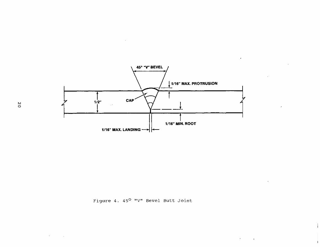
2.6.2 Weld Test
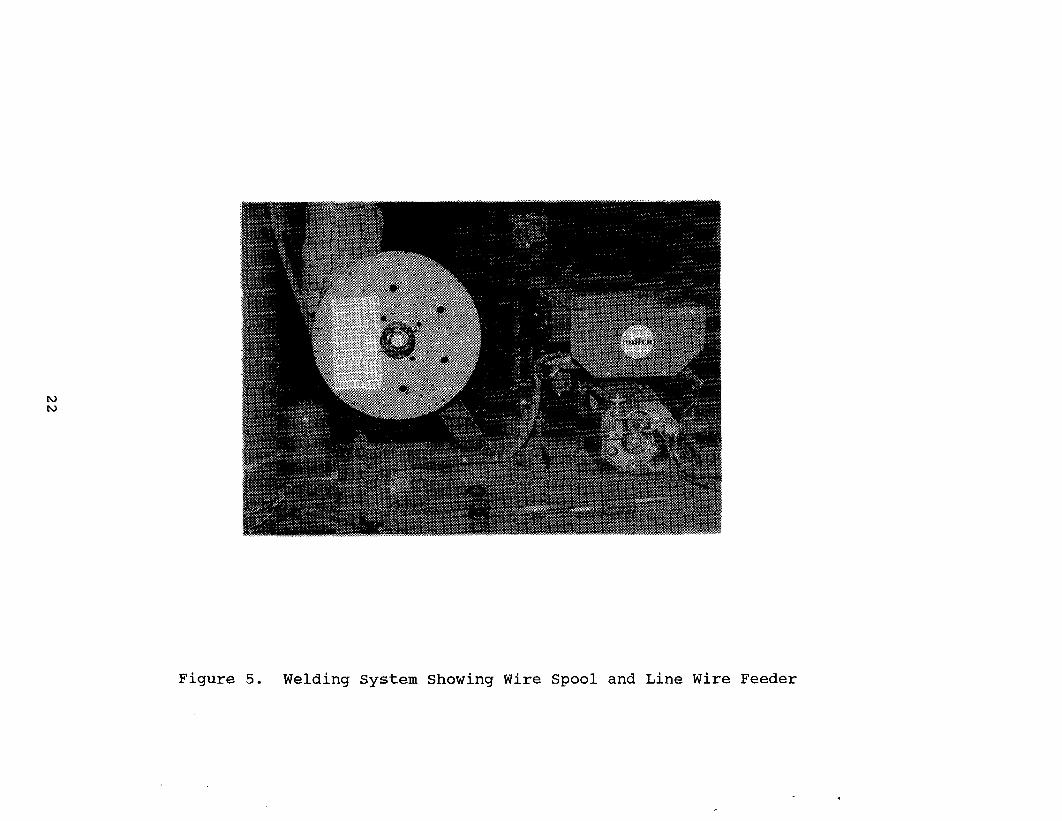
To confirm our decisions on welding procedure andmaterials, a test was conducted. The test wasundertaken on August 1, 1985, in shop conditions(Figure 5). The only deviation from the prescribedprocedure was that the joint was a 370 "VI' bevelinstead of the final design of 450.
The test results are
TIME TIMEWORK DESCRIPTION STARTING ENDING DURATION
First JointSet-up Welder 9:45 am 9:55 am 10 minTack Weld 10:07 10:12 5 minContinuous Weld - 1st Pass 10:12 10:36 24 minRemove slag 10:36 10:38 2 minContinuous Weld - 2nd Pass 10:38 11:13 35 minRemove slag 11:13 11:17 4 minContinuous Weld - 3rd Pass
(Cap) 11:17 11:54 37 minRemove slag 11:54 11:56 2 min
TOTAL 119 min
Second JointTack Weld 1:52 pm 1:57 pm 5 minWeld & Remove Slag-lst Pass 1:57 2:13 16 minWeld & Remove Slag-2nd Pass 2:13 2:38 25 minWeld & Remove Slag-3rd Pass
(Cap) 2:38 3:06 28 min
TOTAL 74 min
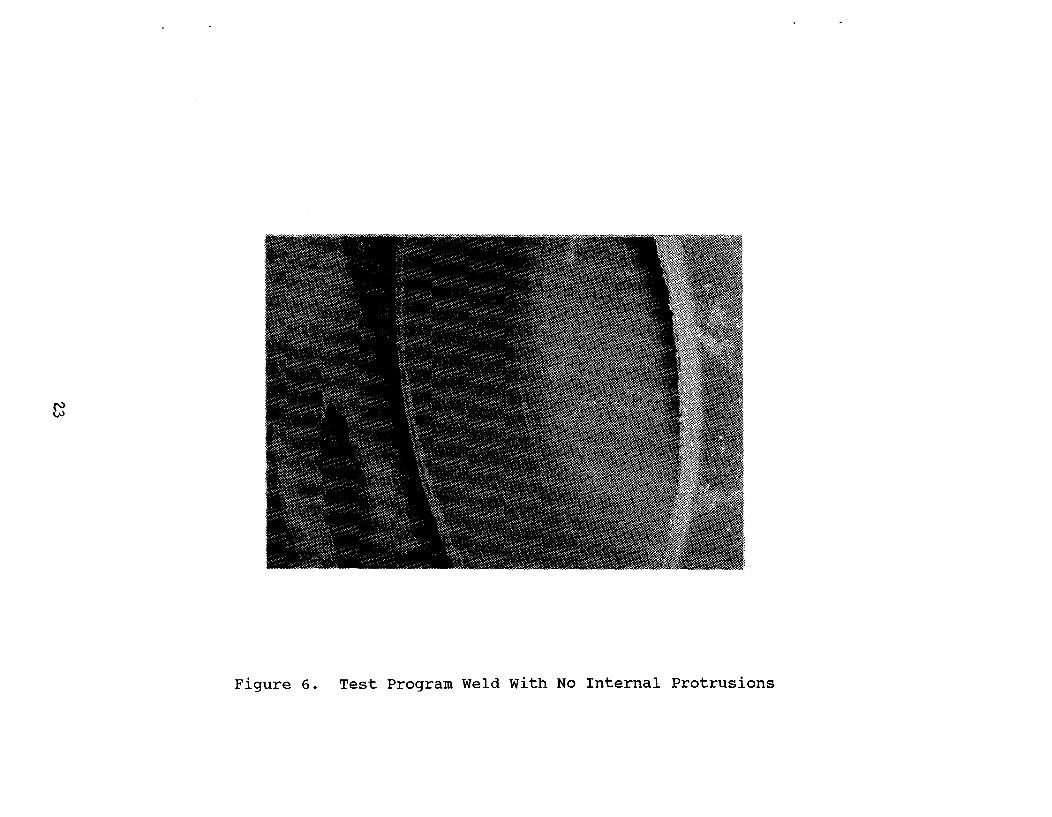
The first joint weld test was concluded to acquaintthe welder with the procedures necessary to producea joint of satisfactory quality. Numerous discus-sions and observations interrupted the actualproduction. The completed joint had no internalprotrusions (Figure 6). The cap weld protruded amaximum of 1/16 in. (Figure 7), which would causeno detrimental effect. Total weld depth averaged1/2-in. in total thickness.
21
rN)
Figure 5. Welding System Showing Wire Spool and Line Wire Feeder
Figure 5. Welding System Showing Wire Spool and Line Wire Feeder
F
Figure 6. Test Program Weld With No Internal Protrusions
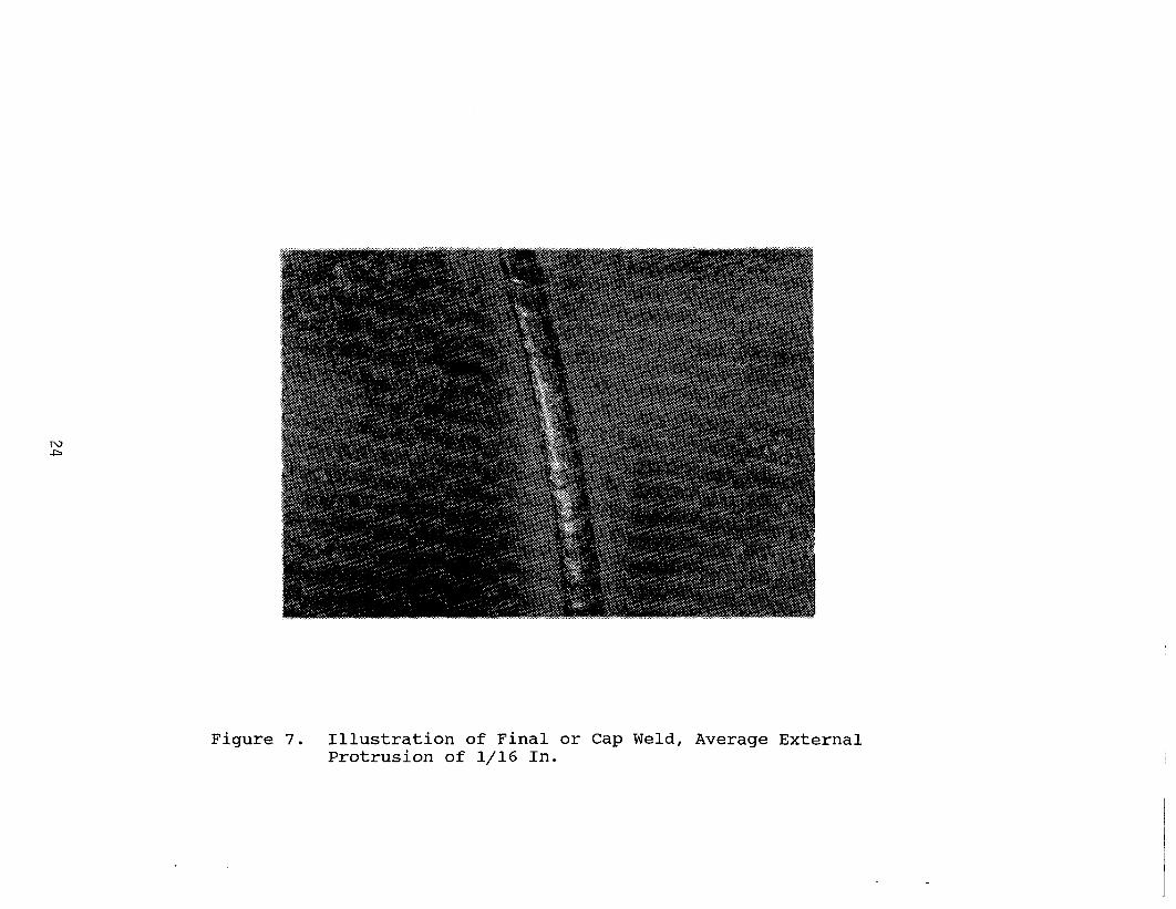
Figure 7. Illustration of Final or Cap Weld, Average ExternalProtrusion of 1/16 In.
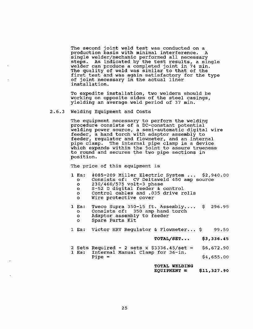
The second joint weld test was conducted on aproduction basis with minimal interference. Asingle welder/mechanic performed all necessarysteps. As indicated by the test results, a singlewelder can produce a completed joint in 74 min.The quality of weld was similar to that of thefirst test and was again satisfactory for the typeof joint necessary in the actual linerinstallation.
To expedite installation, two welders should beworking on opposite sides of the steel casings,yielding an average weld period of 37 min.
2.6.3 Welding Equipment and Costs
The equipment necessary to perform the weldingprocedure consists of a DC-constant potentialwelding power source, a semi-automatic digital wirefeeder, a hand torch with adaptor assembly tofeeder, regulator and flowmeter, and an internalpipe clamp. The internal pipe clamp is a devicewhich expands within the joint to assure truenessto round and secures the two pipe sections inposition.
The price of this equipment is
1 Ea: #085-209 Miller Electric System ... $2,940.00o Consists of: CV Deltaweld 450 amp sourceo 230/460/575 volt-3 phaseo S-52 D digital feeder & controlo Control cables and .035 drive rollso Wire protective cover
1 Ea: Tweco Supra 350-15 ft. Assembly.... $ 296.95o Consists of: 350 amp hand torcho Adaptor assembly to feedero Spare Parts Kit
1 Ea: Victor HRV Regulator & Flowmeter... $ 99.50
TOTAL/SET... $3,336.45
2 Sets Required - 2 sets x $3336.45/set = $6,672.901 Ea: Internal Manual Clamp for 36-in.
Pipe = $4,655.00
TOTAL WELDINGEQUIPMENT = $11,327.90
25
2.7 New Equipment Development. Tests, and Areas of Concern
To expedite the most efficient and economical scheme forthe installation of the steel liners in prebored holes,questionable facets need to be addressed. Among theserequirements are new equipment development, tests, andspecific areas of conpern.
2.7.1 New Equipment Development
The primary equipment used in the installation ofthe 36-in.-diameter steel casing consists of thejacking frame and welding equipment. Both unitsare composed of components currently manufacturedfor use in the existing construction market.However, it is believed that improvements can bemade to each of these particular units, whichwould be beneficial in the installation scheme.
The jacking units quoted within the market surveyconsist of components from equipment supplied forprojects which both auger and jack steel liners.The major drawback to this type of equipment isthe short length of stroke and the need to recyclethe jack reaction frame after each 4-ft to 5-ftstroke. Other problems arise such as the limi-tation of length of liner to be placed being only10 ft by one manufacturer and the overall lengthof 19 ft by another manufacturer. The 10-ftlength limitation would add additional joints,which need to be welded, an approximate 57%increase in the most time-consuming process. The19-ft total length is impractical in the efficientmobilization and setup of the jacking frame.
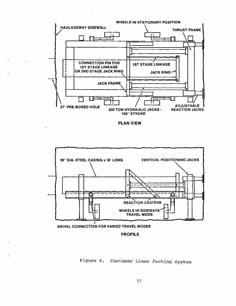
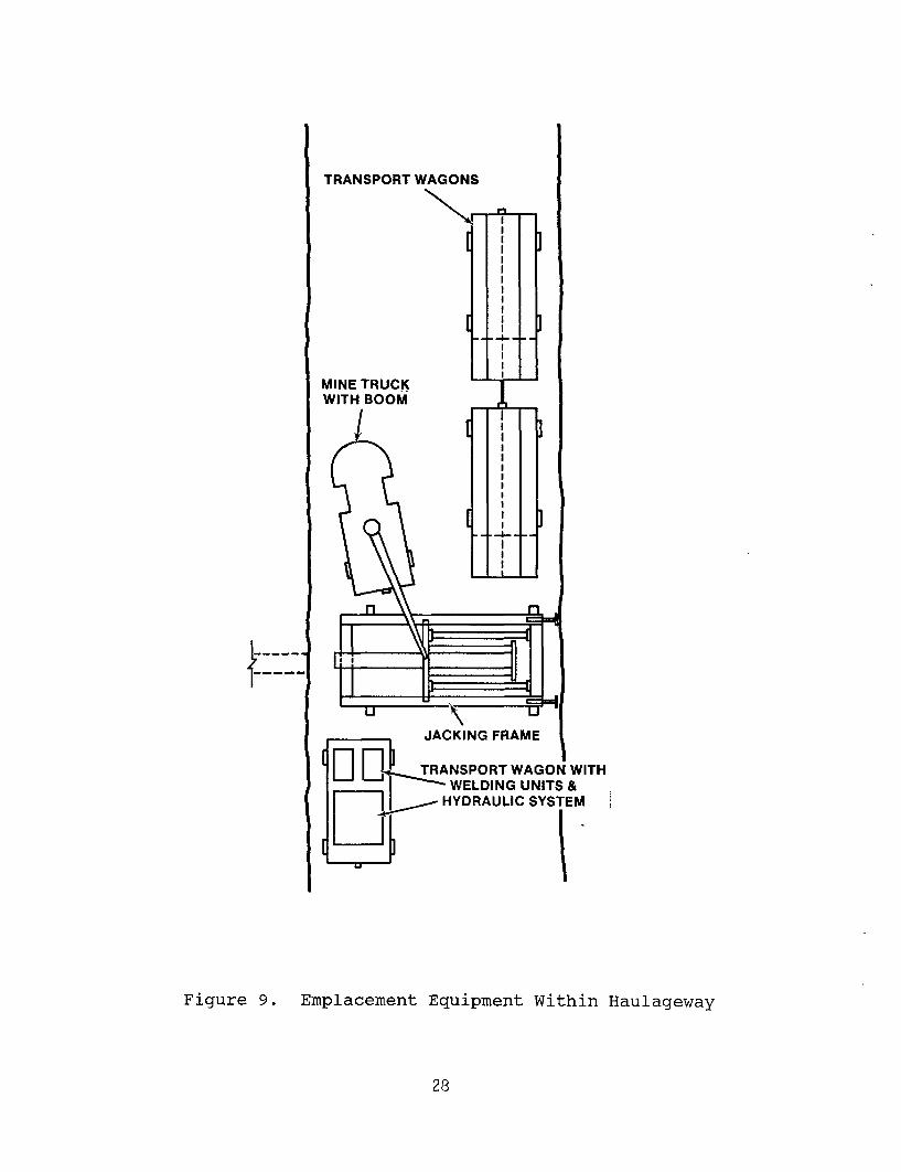
It is common industry practice for contractorsinvolved in reinforced concrete pipe jacking tocustom build jacking frames to meet their specificneeds. Figure 8 illustrates a jacking unit whichwould meet the specific requirements of thisproject. The proposed unit is capable of jacking16-ft lengths of steel casing in two steps. Thefirst step utilizes a linkage system to jack theinitial 8 ft. The links are disconnected and thejack ring is attached directly to the jack frame,and the final 8 ft can then be jacked. Figure 9illustrates the equipment placement within thehaulageway.
26
WHEELS IN STATIONARY POSII HAULAGEWAY SIDEWALL
/ I~~~~~~~-:77 I
TION
THRUST FRAME
EJf1=j- LjL
I lt==L-
7 �I I CONNECTION PIN FOR 1STSTAGE LINKAGEI I N 1ST STAGE LINKAGE
1 ST STAGE LINKAGE jJAKIN jI IOR 2ND STAGE JACK RING JACK RI NG -' .I _ _
11 JACK FRAME } i. \ _ _ ,~I I d
\37"
i /��-1- --I
PRE-BOREC P HOLE200 TON HYDRAULIC JACKS - RE
102" STROKE
ADJUSTABLEACTION JACKS
PLAN VIEW
SWIVEL CONNECTION FOR VARIED TRAVEL MODES
PROFILE
Figure 8. Customer Liner Jacking System
27
TRANSPORT WAGONS
MINE TRUCKWITH BOOM
r'lIIIIIIIIIfII
-4. -
i
i
II
II
II
II
III
I
]
I 3
I J
L
I
I
----
I
JACKING FRAME
TRANSPORT WAGON WITH-WELDING UNITS &- HYDRAULIC SYSTEM
Figure 9. Emplacement Equipment Within Haulageway
28
The electrically driven hydraulic power system iscommercially available and would be mounted on atwo-axle flatbed trailer along with the sets ofwelding machinery. The estimated cost of thetotal jacking system is $119,700.
The liner welding system, used for purposes ofthis report, is the semi-automatic type, whichrequires two welders to hand place the weld.Fully automatic welding in recent years has becomepopular, but because of limitations expressed bymanufacturers' representatives contacted, thismethod was not used. The opinions expressed werethat the side-to-side oscillation necessary in thefinal weld passes could be better controlled forthe quality of weld necessary by hand guidedtechniques. If a fully automatic system could befound which could produce the quality of weldessential for this project, a savings in laborcost could result.
2.7.2 Tests
The process of jacking steel liners is common toexisting construction techniques; however, normaljacking operations are carried out within shaftsseldom deeper than 100 vertical ft. To establishactual costs, it is suggested that a pilot programbe demonstrated within an existing mine withconditions similar to those anticipated of anactual repository site. A minimum of six preboredholes would be needed to aid in evaluation of theactual time and costs related to the installationof the 36-in.-diameter steel casings. Uponcompletion of each liner, a pneumatic orhydrostatic test should be conducted to evaluatethe watertight criteria.
2.7.3 Areas of Concern
The primary areas of concern include the alignmentof the prebored hole, stability of the hole, andthe -10° to +100 deviation from the horizontalaxis.
The alignment of the prebored hole is critical tothe liner jacking process. Deviation will causeadditional frictional and lateral loads to beapplied to the steel liner. Excessive deviationcould cause excessive jacking pressures andstructural failure of the liner. Small deviationscould be compensated for with the addition ofguide shoes on the leading edge of the liner,holding the liner in the center of the hole andpreventing the liner from cutting into theprebored surface.
29
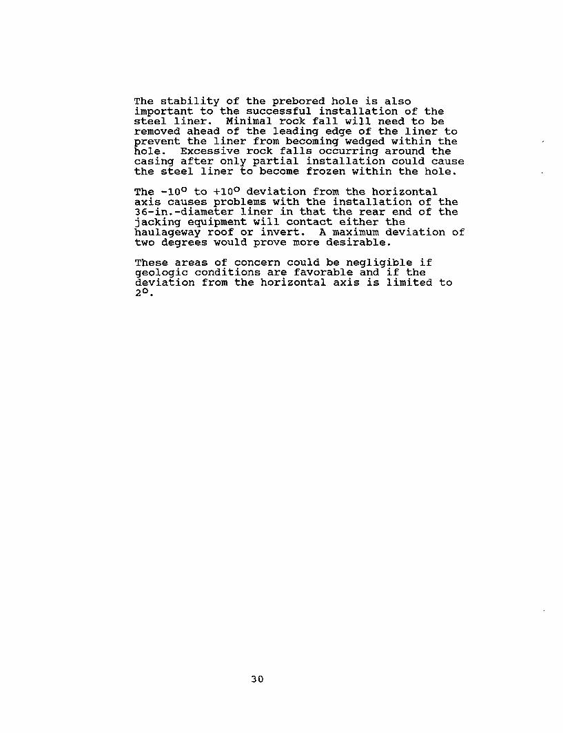
The stability of the prebored hole is alsoimportant to the successful installation of thesteel liner. Minimal rock fall will need to beremoved ahead of the leading edge of the liner toprevent the liner from becoming wedged within thehole. Excessive rock falls occurring around thecasing after only partial installation could causethe steel liner to become frozen within the hole.
The -10° to +100 deviation from the horizontalaxis causes problems with the installation of the36-in.-diameter liner in that the rear end of thejacking equipment will contact either thehaulageway roof or invert. A maximum deviation oftwo degrees would prove more desirable.
These areas of concern could be negligible ifgeologic conditions are favorable and if thedeviation from the horizontal axis is limited to20.
30
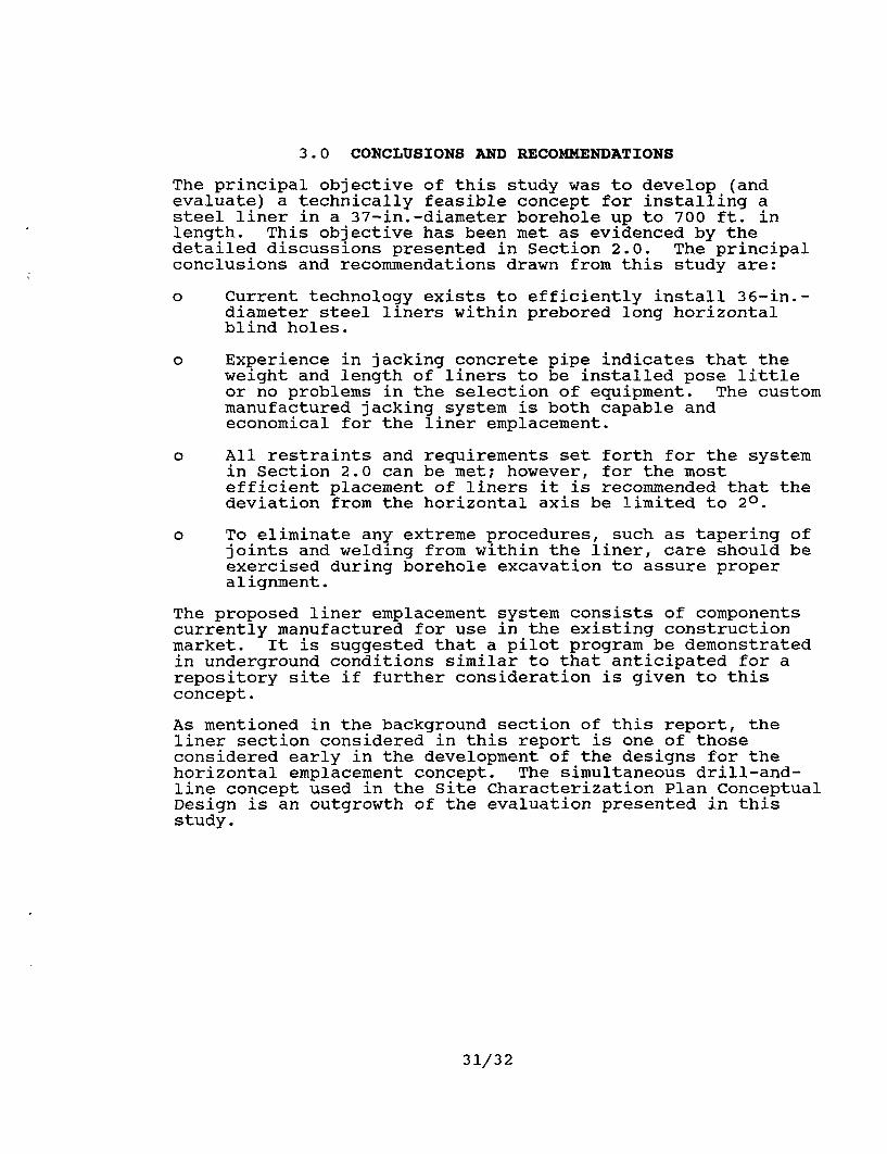
3.0 CONCLUSIONS AND RECOMMENDATIONS
The principal objective of this study was to develop (andevaluate) a technically feasible concept for installing asteel liner in a 37-in.-diameter borehole up to 700 ft. inlength. This objective has been met as evidenced by thedetailed discussions presented in Section 2.0. The principalconclusions and recommendations drawn from this study are:
o Current technology exists to efficiently install 36-in.-diameter steel liners within prebored long horizontalblind holes.
o Experience in jacking concrete pipe indicates that theweight and length of liners to be installed pose littleor no problems in the selection of equipment. The custommanufactured jacking system is both capable andeconomical for the liner emplacement.
o All restraints and requirements set forth for the systemin Section 2.0 can be met; however, for the mostefficient placement of liners it is recommended that thedeviation from the horizontal axis be limited to 20.
o To eliminate any extreme procedures, such as tapering ofjoints and welding from within the liner, care should beexercised during borehole excavation to assure properalignment.
The proposed liner emplacement system consists of componentscurrently manufactured for use in the existing constructionmarket. It is suggested that a pilot program be demonstratedin underground conditions similar to that anticipated for arepository site if further consideration is given to thisconcept.
As mentioned in the background section of this report, theliner section considered in this report is one of thoseconsidered early in the development of the designs for thehorizontal emplacement concept. The simultaneous drill-and-line concept used in the Site Characterization Plan ConceptualDesign is an outgrowth of the evaluation presented in thisstudy.
31/32
APPENDIX
This report contains no data from, or for inclusion in, theRIB and/or SEPDB.
33/34
DISTRIBUTION LIST
B. C. Rusche (RW-1)DirectorOffice of Civilian Radioactive
Waste ManagementU.S. Department of EnergyForrestal BuildingWashington, DC 20585
Ralph Stein (RW-23)Office of Civilian Radioactive
Waste ManagementU.S. Department of EnergyForrestal BuildingWashington, DC 20585
J. J. Fiore, (RW-22)Office of Civilian Radioactive
Waste ManagementU.S. Department of EnergyForrestal BuildingWashington, DC 20585
M. W. Frei (RW-23)Office of Civilian Radioactive
Waste ManagementU.S. Department of EnergyForrestal BuildingWashington, DC 20585
E. S. Burton (RW-25)Siting DivisionOffice of Geologic
RepositoriesU.S. Department of EnergyForrestal BuildingWashington, DC 20585
C. R. Cooley (RW-24).Geosciences & Technology
DivisionOffice of Geologic
RepositoriesU.S. Department of EnergyForrestal BuildingWashington, DC 20585
V. J. Cassella (RW-22)Office of Civilian Radioactive
Waste ManagementU.S. Department of EnergyForrestal BuildingWashington, DC 20585
T. P. Longo (RW-25)Program Management DivisionOffice of Geologic
RepositoriesU.S. Department of EnergyForrestal BuildingWashington, DC 20585
Cy Klingsberg (RW-24)Geosciences and Technology
DivisionOffice of Geologic
RepositoriesU.S. Department of EnergyForrestal BuildingWashington, DC 20585
B. G. Gale (RW-22)Office of Civilian Radio-
active Waste ManagementU.S. Department of EnergyForrestal BuildingWashington, DC 20585
R. J. Blaney (RW-22)Program Management DivisionOffice of Geologic
RepositoriesU.S. Department of EnergyForrestal BuildingWashington, DC 20585
R. W. Gale (RW-40)Office of Civilian Radio-
active Waste ManagementU.S. Department of EnergyForrestal BuildingWashington, DC 20585
J. E. Shaheen (RW-44)Outreach ProgramsOffice of Policy, Integration
and OutreachU.S. Department of EnergyForrestal BuildingWashington, DC 20585
35
J. 0. Neff, ManagerSalt Repository Project OfficeU.S. Department of Energy505 King AvenueColumbus, OH 43201
D. C. Newton (RW-23)Engineering & Licensing Div.Office of Geologic
RepositoriesU.S. Department of EnergyForrestal BuildingWashington, DC 20585
0. L. Olson, ManagerBasalt Waste Isolation Project
OfficeRichland Operations OfficeU.S. Department of EnergyPost Office Box 550Richland, WA 99352
Carl P. Gertz, Project Mgr(4)Waste Management Project
OfficeU.S. Department of EnergyPost Office BoxLas Vegas, NV
D. F. Miller, DirectorOffice of Public AffairsU.S. Department of EnergyPost Office Box 14100U.S. Departmentiof EnergyLas Vegas, NV 89114
P. M. Bodin (12)Office of Public AffairsU.S. Department of EnergyPost Office Box 14100Las Vegas, NV 89114
B. W. Church, DirectorHealth Physics DivisionU.S. Department of EnergyPost Office Box 14100Las Vegas, NV 89114
Chief, Repository ProjectsBranch
Division of Waste ManagementU.S. Nuclear RegulatoryCommission
Washington, DC 20555
Document Control CenterDivision of Waste ManagementU.S. Nuclear Regulatory
CommissionWashington, DC 20555
S. A. Mann, ManagerCrystalline Rock Project
OfficeU.S. Department of Energy9800 South Cass AvenueArgonne, IL 60439
K. Street, Jr.Lawrence Livermore National
LaboratoryPost Office Box 808Mail Stop L-209Livermore, CA 94550
L. D. Ramspott (3)Technical Project Officer for
NNWSILawrence Livermore National
LaboratoryP.O. Box 808Mail Stop L-204Livermore, CA 94550
W. J. Purcell (RW-20)Associate DirectorOffice of Civilian Radio-
active Waste ManagementU.S. Department of EnergyForrestal BuildingWashington, DC 20585
D. T. Oakley (4)Technical Project Officer for
NNWSILos Alamos National
LaboratoryP.O. Box 1663Mail Stop F-619Los Alamos, NM 87545
W. W. Dudley, Jr. (3)Technical Project Officer for
NNWSIU.S. Geological SurveyPost Office Box 25046418 Federal CenterDenver, CO 80225
36
NTS Section LeaderRepository Project BranchDivision of Waste ManagementU.S. Nuclear Regulatory
CommissionWashington, DC 20555
V. M. GlanzmanU.S. Geological SurveyPost Office Box 25046913 Federal CenterDenver, CO 80225
P. T. PrestholtNRC Site Representative1050 East Flamingo RoadSuite 319Las Vegas, NV 89109
M. E. SpaethTechnical Project Officer for
NNWSIScience Applications
International CorporationSuite 407101 Convention Center DriveLas Vegas, NV 89109
SAIC-T&MSS Library (2)Science Applications
International CorporationSuite 407101 Convention Center DriveLas Vegas, NV 89109
W. S. Twenhofel, ConsultantScience Applications
International Corp.820 Estes StreetLakewood, CO 89215
A. E. GurrolaVice President and General
ManagerEnergy Support DivisionHolmes & Narver, Inc.Mail Stop 580Post Office Box 14340Las Vegas, NV 89114
J. A. Cross, ManagerLas Vegas BranchFenix & Scisson, Inc.Mail Stop 514Post Office Box 14308Las Vegas, NV 89114
Neal Duncan (RW-44)Office of Policy,
Integration, and OutreachU.S. Department of EnergyForrestal BuildingWashington, DC 20585
J. S. WrightTechnical Project Officer for
NNWSIWestinghouse Electric
CorporationWaste Technology Services
DivisionNevada OperationsPost Office Box 708Mail Stop 703Mercury, NV 89023
ONWI LibraryBattelle Columbus LaboratoryOffice of Nuclear Waste
Isolation505 King AvenueColumbus, OH 43201
W. M. Hewitt, Program ManagerRoy F. Weston, Inc.955 L'Enfant Plaza,
Southwest, Suite 800Washington, DC 20024
H. D. CunninghamGeneral ManagerReynolds Electrical &
Engineering Co., Inc.Post Office Box 14400Mail Stop 555Las Vegas, NV 89114
T. Hay, Executive AssistantOffice of the GovernorState of NevadaCapitol ComplexCarson City, NV 89710
R. R. Loux, Jr., Director (3)Nevada Agency for Nuclear
ProjectsNuclear Waste Project OfficeState of NevadaCapitol ComplexCarson City, NV 89710
37
C. H. Johnson, TechnicalProgram ManagerNevada Agency for Nuclear
ProjectsNuclear Waste Project OfficeState of NevadaCapitol ComplexCarson City, NV 89710
John FordhamDesert Research InstituteWater Resources CenterPost Office Box 60220Reno, NV 89506
Department of ComprehensivePlanning
Clark County225 Bridger Avenue, 7th FloorLas Vegas, NV 89155
Lincoln County CommissionLincoln CountyPost Office Box 90Pioche, NV 89043
Community Planning and'Development
City of North Las VegasPost Office Box 4086North Las Vegas, NV 89030
City ManagerCity of HendersonHenderson, NV 89015
N. A. NormanProject ManagerBechtel National Inc.P.O. Box 3965San Francisco, CA 94119
Flo ButlerLos Alamos Technical
Associates1650 Trinity DriveLos Alamos, NM 87544
Timothy G. BarbourScience Applications
International Corporation1626 Cole Boulevard, Suite 270Golden, CO 80401
E. P. BinnallField Systems Group LeaderBuilding 50B/4235Lawrence Berkeley LaboratoryBerkeley, CA 94720
Dr. Martin MifflinDesert Research InstituteWater Resources CenterSuite 12505 Chandler AvenueLas Vegas, NV 89120
Planning DepartmentNye CountyPost Office Box 153Tonopah, NV 89049
Economic DevelopmentDepartment
City of Las Vegas400 East Stewart AvenueLas Vegas, NV 89101
Director of CommunityPlanning
City of Boulder CityPost Office Box 367Boulder City, NV 89005
Commission of theEuropean Communities
200 Rue de la LoiB-1049 BrusselsBELGIUM
Technical Information CenterRoy F. Weston, Inc.955 L'Enfant Plaza,
Southwest, Suite 800Washington, DC 20024
R. HarigParsons Brinckerhoff Quade &
Douglas, Inc.1625 Van Ness AvenueSan Francisco, CA 94109-3678
Dr. Madan M. Singh, PresidentEngineers International, Inc.98 East Naperville RoadWestmont, IL 60559-1595
38
Roger HartItasca Consulting Group, Inc.P.O. Box 14806Minneapolis, MN 55414
T. H. Isaacs (RW-22)Office of Civilian Radio-
active Waste ManagementU.S. Department of EnergyForrestal BuildingWashington, DC 20585
D. H. Alexander (RW-23)Office of Civilian Radio-
active Waste ManagementU.S. Department of EnergyForrestal BuildingWashington, DC 20585
B. J. King, Librarian (2)Basalt Waste Isolation Project
LibraryRockwell Hanford OperationsPost Office Box 800Richland, WA 99352
David K. ParrishRE/SPEC Inc.3815 Eubank, N.E.Albuquerque, NM 87191
D. L. Fraser, General ManagerReynolds Electrical &
Engineering Co., Inc.Mail Stop 555Post Office Box 14400Las Vegas, NV 89114-4400
Gerald Parker (RW-25)Office of Geologic
RepositoriesU.S. Department of EnergyForrestal BuildingWashington, DC 20585
J. P. Knight (RW-24)Office of Civilian Radio-
active Waste ManagementU.S. Department of EnergyForrestal BuildingWashington, DC 20585
Allen Jelacic (RW-23)Office of Civilian Radio-
active Waste ManagementU.S. Department of EnergyForrestal BuildingWashington, DC 20585
J. R. RolloDeputy Assistant Director
for Engineering GeologyU.S. Geological Survey106 National Center12201 Sunrise Valley DriveReston, VA 22092
R. Lindsay MundellUnited States Bureau of MinesP.O. Box 25086Building 20Denver Federal CenterDenver, CO 80225
Vincent GongTechnical Project Officer for
NNWSIReynolds Electrical &
Engineering Co., Inc.Mail Stop 615Post Office Box 14400Las Vegas, NV 89114-4400
Christopher M. St. JohnJ. F. T. Agapito Assoc., Inc.27520 Hawthorne Blvd.,;Suite 137Rolling Hills Estates, CA 90274
J. P. PedalinoTechnical Project Officer for
NNWSIHolmes & Narver, Inc.Mail Stop 605Post Office Box 14340Las Vegas, NV 89114
Eric AndersonMountain West Research-
Southwest, Inc.398 South Mill Ave., Ste. 300Tempe, AZ 85281
39
Judy Foremaster (5)City of CalientePost Office Box 158Caliente, NV 89008
S. D. MurphyTechnical Project Officer for
NNWSIFenix & Scisson, Inc.Mail Stop 940Post Office Box 15408Las Vegas, NV 89114
S. H. Kale (RW-20)Associate DirectorOffice of Civilian Radio-
active Waste ManagementU.S. Department of EnergyForrestal BuildingWashington, DC 20585
630063106310
631163116311631263136314631463146314631463146315633264303141315180243154-3
6310
R. W. LynchT. 0. Hunter22/124221/21-2633/REP-II/NQA. StevensC. MoraV. Hinkel (2)F. W. BinghamT. E. Blej wasJ. R. TillersonR. J. FloresD. A. GlowkaR. E. StinebaughC. W. TuckerK. D. Young (10)S. SinnockWMT Library (20)N. R. OrtizS. A. Landenberger (5)W. L. Garner (3)P. W. DeanC. H. Dalin (28)for DOE/OSTINNWSICF
40