Embed Size (px)
Citation preview
SAP: The Essential Guide
For Dwelling Designers And Architects
By Mike Andrews
‘The overall aim is to give the dwelling
designer a better understanding of what
SAP is, how it is used to demonstrate
compliance with Building Regulations
Part L1A, the information required by an
assessor to complete the calculations,
and which of the many input fields has
the greatest impact on the overall
results’

1 | P a g e
SAP (Standard Assessment Procedure): The Essential Guide For Dwelling Designers And Architects How it works, what input is required, and what makes a difference to achieving a pass Contents Preface Introduction PART ONE SAP and Building Regulations, SAP Software and Compliance With Part L1A Conservation of Fuel and Power Part L Approved Documents: Dwellings SAP – Simplified Process Map New Dwellings: TER/DER and TFEE/DFEE SAP Rating EPC Rating and Environmental Impact Rating (EI) Model Dwelling SAP Conventions: Summary of SAP Input, The Requirements For SAP Assessment and EPC Conventions, and What Achieves The Best Results Section 1: Drawings Section 2: Job Details Section 3: Heat Loss Floors Section 4: Heat Loss Walls Section 5: Heat Loss Roofs Section 6: Openings Section 7: Thermal Bridges Section 8: Ventilation Section 9: Space Heating Section 10: Water Heating Section 11: Renewables Section 12: Other

2 | P a g e
PART TWO SAP Input: The Details Drawings Measurement Conventions and What is Included SAP Input fields: General Information SAP and Building Regulations Compliance Structure of SAP Input – Each Section in SAP Section 1: Job Details Section 2: Dwelling Section 3: Heat Loss Floors Section 4: Heat Loss Walls Section 5: Heat Loss Roofs Section 6: Openings and Summer Overheating Section 7: Thermal Bridging. Non-Repeating Thermal Bridges Section 8: Ventilation Section 9: Heating Section 10: Domestic Hot Water (DHW) Section 11: Renewables Section 12: Other SAP Input PART THREE What is Part L1A? SAP 2012 (NCM) and The TER SAP Output Documents Assessors, Accreditation Schemes and The Rules We Have to Follow About The Author Appendices Appendix 1: Construction Details, Organisations
Appendix 2: List of Tables Appendix 3: SAP 2012 version 9.92 (October 2013), Reference Tables Appendix 4: New Build Checklist Appendix 5: As-Built SAP Checklist
Sources and Further Information Glossary & Index

3 | P a g e
Preface I decided to write this book firstly to help dwelling designers, be they architects, contractors or self-builders, to understand what SAP is, what it does and doesn’t do, and what information is required for the calculation. Secondly, I aim to explain which parts of this input information have the most influence on the end result, and why. I have completed hundreds of SAP assessments and lost count of the times a dwelling designer has met the minimum requirements of Part L, yet their dwelling fails, and the designer is left wondering how that could be. This book will provide the answers.
I’ve also taken the unusual step of presenting the book backwards. Everyone is busy, and I for one don’t like having to read my way through a whole book full of detail to get to the point right at the end. Therefore, after a brief introduction, I’ve written what really matters first – in a nutshell, so to speak. After that, if the reader wants to go into the details – and I suggest you do for a full understanding – it’s all there in Parts Two and Three.
Special thanks to Ben Smith at Batterham Matthews Architects for his input, and
thanks also to Batterham Matthews Architects, and Favonius Architects for the use of their excellent drawings.
Feedback is always welcome. If you want to contact me, please do so at: [email protected] Mike Andrews

4 | P a g e
Introduction To complete a SAP assessment and eventual Energy Performance Certificate (EPC) there are many input fields requiring information about the proposed dwelling that require entering into the chosen software. Some of these place the dwelling in a context, for example its address and built form, whilst others account for the performance and have a fundamental impact on the result. The aim of this book is to demonstrate the whole SAP input process and, by doing so, to demonstrate what factors affect the final result, and by how much. It also aims to show the process and information required by the dwelling designer for each input field in the software.
In summary, the overall aim is to give the dwelling designer a better understanding of what SAP is, how it is used to demonstrate compliance with Building Regulations Part L1A, the information required by an assessor to complete the calculations, and which of the many input fields have the greatest impact on the overall results.
The book has been written by an accredited SAP assessor and EPC provider, an
On Construction Domestic Energy Assessor (OCDEA) with information compiled from official SAP documentation, and the author’s own knowledge and experience from completing many SAP assessments over several years. A list of sources is provided at the end of the book.
The book is written in three parts: Part One outlines what the SAP process is, and
what is usually needed to gain a pass. Part Two looks in detail at the SAP input fields, what information is required and the effect this has on the overall SAP result. Part Three looks beyond the SAP calculation and focuses on what information is required to satisfy Building Regulations Part L1A.
Unlike many technical books, this one aims to be different by giving the reader
most of the answers at the beginning, without the need to read the whole thing! You can find these in Part One.
However, to really understand how the process works, I would suggest at least
reading each Section in Part Two. To help focus on the important issues, each one is summarised with the key points. If you only read one thing, go straight for these summaries at the end of each Section. They are highlighted in blue.
Part Two is for those who already have an awareness of SAP and have worked
with an assessor in gaining Building Regulations for Part L1A. So this section allows these readers to ‘dive right in’ and understand why some dwellings pass ok, whilst others are more of a challenge.
For the more technical or curious reader, Part Three is written in a similar way to
our previous documents on Part L1B and L2A, providing as it does the background information and knowledge about how the software and the calculation methodology work in relation to one another.

5 | P a g e
One of the reasons for writing this book is to show the effect that individual input can have on the results. However, the calculation works as a whole, and although there is a Model/Notional Dwelling in the calculation that must be equalled or bettered, and there are minimum back-stop values in the Building Regulations that must be equalled or bettered, the calculation process is flexible, and deliberately so. Therefore, whilst some performance values may be better than the Model/Notional Dwelling, some could be a good deal worse. If the resulting CO2 emissions and fabric energy efficiency targets are achieved, that’s fine. Therefore, although I have taken the various inputs into the SAP calculation separately, to show how these affect the result, in reality they all work together to achieve that final result.
At the time of writing (Winter 2016/2017), there are some changes planned to
Part L after a Government Consultation. These are not mentioned in this book as they are still to be decided. However, once the changes are known, this book will be updated accordingly. Any purchasers of the original will be offered a replacement for a nominal fee.

6 | P a g e
PART ONE SAP and Building Regulations, SAP Software and Compliance With Part L1A There are various SAP software packages offered by each of the accreditation schemes, for example NHER Plan Assessor, Stroma FSAP and Elmhurst Design SAP. They are all formatted differently but the input required and the outputs gained are all the same. This ensures there is a consistency in the reporting, irrespective of which software is used, or which scheme.
For the purposes of this document, I have used NHER Plan Assessor as the main test software, checking for consistency using the Stroma FSAP software.
The latest edition of the SAP software (SAP 2012) is formatted to produce
compliance documents for Building Regulations Part L1A in England 2013. It can also be used to demonstrate compliance for Part L1A Wales (2014), and Section 6 (2015) in Scotland. For Northern Ireland SAP 2009 is used. In total there are a minimum of approximately 140 input fields, and that’s with only one heat loss floor, wall, roof and one opening for a basic two-bedroom, end-of-terrace dwelling! This number can easily be doubled. It’s important to know, therefore, which of these input fields the dwelling designer must provide to the assessor, which can be influenced, and which have the greatest impact on the final SAP result. This section of the document will explain that.
Full details of the SAP calculation and procedure are available in the following
document: The Government’s Standard Assessment Procedure for Energy Rating of Dwellings
2012 Edition. Where SAP Default Values are quoted throughout this book, full details can be
found in the above. It is freely available to download from: https://www.bre.co.uk/sap2012/page.jsp?id=2759#

7 | P a g e
Conservation of Fuel and Power The requirement of Building Regulations Part L 2010 (with later amendments) is that reasonable provision shall be made for the conservation of heat and power by limiting heat gains and losses through the building fabric and services, by providing energy-efficient services and controls, and by providing the building’s owner with sufficient information for efficient operation and maintenance.
The regulations are divided into L1 for dwellings, and L2 for non-dwellings. Furthermore, L1A is for new dwellings, L1B for existing dwellings and, likewise,
L2A for new non-dwellings, L2B for existing non-dwellings. The above Regulations are also slightly different for England, Wales, Scotland and
Northern Ireland and each have their own Approved Documents. This book will focus on England only. The Welsh Regulations have many similarities to England, whilst Scotland and Northern Ireland differ in their approach. However, the SAP compliance software, the information required for the calculation, and the process followed are the same for all countries and, once a postcode is entered into the software, the appropriate Regulations are automatically applied to the calculation.
Part L Approved Documents: Dwellings
Approved Document L1A: Conservation of fuel and power (New dwellings); (2013 edition for use in England)

8 | P a g e
Approved Document L1A: Conservation of fuel and power (New dwellings); (2014 edition for use in Wales)
In Scotland, Regulations apply as follows:
• Technical Handbooks 2015 Domestic – Energy In Northern Ireland, Regulations apply as follows:
• Technical Booklet F1 Conservation of fuel and power in Dwellings 2012
Second Tier Supporting Documents
Domestic Building Services Compliance Guide 2013 – England

9 | P a g e
SAP – Simplified Process Map
*1 See Appendix 4: New Build Checklist – to be used at Design Stage to provide the required information
for the SAP Calculation.
*2 See Appendix 5: As-Built SAP Checklist – to be used upon completion of the build for confirmations required for Building Control and Energy Performance Certificate.
Dwelling Designer
provides Drawings and
Specification*1
SAP Assessor checks
information and
completes calculations
Designer agrees SAP
input or reviews after
advice if dwelling does
not pass
Once dwelling passes,
SAP submitted to
Building Control before
work starts on site
Construction begins; any
changes from
specification notified to
SAP Assessor
Upon completion, air test
carried out and As-Built
confirmations provided to
SAP Assessor*2
SAP Assessor checks all
As-Built confirmations to
ensure compliance
Assessor lodges EPC
and provides As-Built
submission to Building
Control

10 | P a g e
New Dwellings: TER/DER and TFEE/DFEE For new dwellings, compliance must be demonstrated by SAP calculations comparing CO2 emissions (kg CO2/m2/year) expressed as a Dwelling Emission Rate (DER) against a Target Emission Rate (TER). The DER must be equal to or lower than the TER. The DER is derived from all the SAP input.
The TER is calculated using a Notional Dwelling based on a Model Dwelling contained in Appendix R of SAP 2012. The calculation is shown below:
TER2013 = CH x FF + CPF + CL CH = carbon from space and hot water heating CL = carbon from internal lighting CPF = carbon from pumps and fans FF = fuel factor The TER is estimated using a parallel SAP calculation based on the same
dimensions as the proposed dwelling but using a set of reference values for the building fabric and the heating systems, etc.
These reference values include U-Values for the main building elements, specific
psi values for all junctions, a gas-fired boiler with radiators (with SEDBUK 89.5%), natural ventilation with extract fans, an air permeability of 5 m3/hm2 at 50 Pa and 100% of fixed lighting outlets being low-energy fittings.
It is this parallel dwelling from Appendix R of the SAP 2012 document that is also
the Model Dwelling found in Section 5: Model Designs from Approved Document L1A 2013 Edition.
There is also a requirement that the fabric energy efficiency, expressed as a
Dwelling Fabric Energy Efficiency (DFEE), is lower than the Target Fabric Energy Efficiency (TFEE). The DFEE is derived from the dwelling size and shape, U-Values, Air Permeability, Thermal Bridging, Thermal Mass and the number of Extract Fans and Open Flues present, and is a calculation that works out the demand energy requirement, both heating, and cooling, if present (kWh/m2/year). The TFEE rate is calculated by determining the fabric energy efficiency from a Notional Dwelling constructed according to the reference values in Table 1, below. The fabric energy efficiency is then multiplied by a factor of 1.15 (15%) to give the TFEE rate. This 15% reduction was derived from a higher FEE target originally set by the Government but was relaxed for the introduction of Part L 2013.
The TER and TFEE are figures automatically generated by the compliance
software, and are based on performance values set in the calculation, but using the same building shape, size and orientation as the proposed dwelling.
Both DER/TER and DFEE/TFEE are calculated at both design stage and again once the building is completed.
The dwelling must also achieve minimum standards of thermal efficiency in both
the construction element U-Values and air tightness, the risk of overheating in

11 | P a g e
summer must be avoided by careful design of ventilation, glazing orientation and shading, and the construction should be designed to meet minimum standards to avoid significant Thermal Bridging. Therefore, a fabric-first approach should be adopted.
Building Services should meet the minimum requirements for efficiency and use of
appropriate controls as determined in the Domestic Building Services Guide. A strategic approach should be adopted where the aim is to reduce energy
demands overall, meet the remaining energy demand with high-efficiency systems that are well controlled, and then consider the use of renewable energy to offset the energy demand. A renewable energy system should not be used as a basis for a poorly insulated building.
To help gain compliance, if the maximum U-Value targets, minimum system
efficiencies etc, as stated in Part L Approved Documents, were followed, it’s highly unlikely that the dwelling would pass. This is because the Notional or Model Dwelling, the one forming the TER and TFEE, is using values that are much lower than those in the Part L Approved documents. See Table 1, below. SAP Rating Where does the SAP rating fit in?
The SAP rating is a way of comparing dwellings, 1 being the lowest (like a tent), and 100+ being the best (Zero Carbon). The average dwelling in the UK is around 50; most new builds are up in the 80s.
The rating is calculated by estimating the average fuel costs, divided by the floor
area, and then adjusted to fit on the scale of 1–100+. The fuel costs are not the actual costs to the dwelling; they are taken from the Government Building Research Establishment Energy Model (BREDEM) calculation. It’s shown on the SAP Worksheet. This is not actual predicted energy use (kWh/yr) although it can be reasonably accurate, however it only includes regulated energy, not unregulated energy such as cooking, small electrics etc. It’s not possible to directly compare this energy use with other energy modelling, for example Passivhaus Planning Package (PHPP), mainly because the measurement conventions are different. For example, PHPP measures externally and SAP measures internally.

12 | P a g e
Example SAP Worksheet Showing SAP Rating
EPC Rating and Environmental Impact Rating (EI) The EPC rating is the SAP rating above but divided up into bands A–G. An average UK dwelling would be an E; an average new build, B–C; a zero-carbon home an A; and a tent, G.
The EI is based on the estimated CO2 emissions per m2 from space heating/cooling, water heating, ventilation and internal lighting, minus CO2 emissions saved by electricity generation. It’s expressed in the same way as the EPC rating 0–100 and A–G.

13 | P a g e
Example EPC Showing EPC Ratings

14 | P a g e
Model Dwelling Table 1: Model Dwelling England (TER/TFEE) Values Compared to Part L Regulations
Element Value Model Building
(TER/TFEE)
Building
Regulations 2013 England
Opening area Same as the proposed dwelling to
25% of floor area N/A
External walls 0.18 W/(m2K) 0.3 W/(m2K)
Party walls 0 W/(m2K) 0.2 W/(m2K)
Floor 0.13 W/(m2K) 0.25 W/(m2K)
Roof 0.13 W/(m2K) 0.2 W/(m2K)
All windows 1.4 W/(m2K) 2 W/(m2K)
Opaque doors 1 W/(m2K) 2 W/(m2K)
Semi-glazed doors 1.2 W/(m2K) 2 W/(m2K)
Air tightness 5 m3/(h.m2) 10 W/(m2K)
Linear thermal
transmittance SAP psi values or 0.05 W/(m2K) if
actual is 0.15 W/(m2K) 0.15 W/(m2K)
Ventilation Natural with extract fans (2 fans up to 70m2 TFA; 3 fans 70–100m2 TFA;
4 fans over 100m2 TFA)
N/A
Air conditioning None
Heating: gas boiler
with fan flue to
radiators 89.5% efficiency 88% efficiency
Heating controls Time and temperature zone control,
weather comp, modulating boiler with interlock
Programmer, room
stat and TRVs, interlock
DHW system Heated by boiler; if cylinder specified
150 ltrs in heated space, cylinder
stat and separate time control
Cylinder stat and separate time
control
Primary pipe work Fully insulated Fully insulated
Hot water cylinder loss
factor if specified Equal or better than 0.21 kWh/day 0.32 kWh/day
Secondary heating None N/A
Lighting 100% low energy 75% low energy
Thermal Mass
Parameter (TMP) Medium = 250 (masonry
construction) N/A
As can be seen from Table 1, above, the values for the building fabric in the Model Dwelling are considerably lower than the maximum allowed to achieve values in the Part L Approved Document, and therefore these Model Dwelling figures should be used as the basis for forming any targets to achieve in a design. It should be noted, however, that the SAP calculation works by taking all the above inputs into account, therefore if one performance value is better than the above, another can be less, and vice versa. A design strategy in terms of energy efficiency needs to encompass ALL input into the SAP calculation as it’s the overall DER and DFEE figures, derived from the input, that will determine if the dwelling passes or fails.
Table 1, above, is taken from Approved Document L1A 2013 England Section 5 Model Designs and, if it is followed, the dwelling would normally pass.

15 | P a g e
Similar information is available in Appendix B Approved Document L1A Wales. There you have it. If you follow the Model Design as indicated in the Approved
Document, your dwelling will pass. Unfortunately, it often does not. Throughout this book, I will be referring to test dwellings. These are eight
different but typical dwelling types that I have used to test and compare the SAP results.
They are:
• Ground floor, mid floor/top floor flats • Mid and end terrace house • Semi detached house (effectively the same as an end terrace)
• Standard detached house (same floor area on the ground and first floor)
• Non-standard detached house (differing floor areas, dormers etc) The results from entering the Model Building into the SAP for these real examples
demonstrates that not all will pass Criterion C1, the DER/TER, using the standard Model Dwelling specification (see Table 2, below). Fortunately, they do all pass the Fabric Energy Efficiency Criteria.
In my experience, the DER fail is usually because of two issues: First, if there is no secondary heating specified in the proposed dwellings. The
Model Design also does not have secondary heating, but as soon as secondary heating (one that is additional to the main source of heating and usually in the living room of the dwelling) is specified, it will often pass, although this would often be a closed wood burner rather than a gas fire. If secondary heating cannot be specified, then something else within the calculations must be improved so that it is better than the Model Dwelling Value.
Second, The Dwelling Fabric Energy Efficiency Value can largely be down to how
the Thermal Bridging psi values are defined. Here, Approved Construction Details (ACDs) or better alternatives usually need to be specified unless considerably better U-Values than the Model Dwelling are specified throughout the remainder of the calculation. For more details see Part Two, Section 7.
The main reason I believe the above Test Dwellings and other real assessments
do not pass Criterion 1 is because there is no secondary heating specified, or it’s the psi values applied in the Thermal Bridging calculation in the proposed dwellings.
More on this in Part Two, Section 8.

16 | P a g e
Table 2: Test Dwellings: SAP Results Using the Model Dwelling Values From Table 1
Dwelling
Type Built Form DER TER Var % DFEE TFEE Var %
House Detached 16.18 15.73 102.87 51.59 55.58 92.82
House Semi detached 15.10 14.29 105.66 47.79 49.42 96.70
House End terrace 19.32 18.76 103.00 49.80 51.20 97.26
House Detached 19.37 18.46 104.96 60.62 62.85 96.44
House Mid terrace 18.04 17.60 102.52 44.02 45.16 97.48
Flat Top Floor 16.40 16.66 98.42 40.42 45.09 89.64
Flat Ground floor 16.07 16.31 98.53 39.93 44.59 89.53
Flat Mid floor 14.98 14.67 102.07 35.93 37.29 96.35
SAP Conventions SAP Conventions or SAP Default Values apply to SAP 2012 throughout the UK. Conventions applied for design-stage calculations submitted to Building Control are usually carried through to the As-Built stage unless there has been an update between the two, in which case the latest Conventions apply. SAP provides Default Values for many of the input fields, e.g. window U-Values and boiler efficiency.
Whenever specific product information is available, that should be used rather than Default Values, and of course will usually give a better result.
However, when using any specific values there needs to be documentary
evidence to support them, and such evidence should be made available to Building Control upon request.
For items using the Product Database, the evidence required is that the specific
named product, e.g. boiler, is the one being used. At the end of each Section in Part Two the specific requirements of the SAP Conventions relevant to that Section are listed.
In a Nutshell: A Summary of SAP Input, the requirements for a SAP assessment
and EPC Conventions, and what achieves the best results. The full effect of how the various input in SAP affects the final result and whether
the dwelling will pass the Building Regulations is covered in depth in Part Two. This next section summarises all of Part Two. Therefore, if you want to gain an overview of what really makes a difference in SAP, this section will cover that.
All input is referenced to the effect each has on the DER and DFEE figures, as
these are the two main criteria for a pass in SAP. Both must be equal to or lower than the target figures, TER and TFEE.

17 | P a g e
Section 1: Drawings The only way to get an accurate assessment completed is from a good set of design drawings and a specification. The minimum drawings required are as follows:
• Site Plan • Floor Plans • Elevation Drawings • Sections Drawings through all orientations
I have been asked to carry out calculations where at least one of the above may
be missing, especially Sections (I won’t, by the way), but to provide a calculation of any worth all of the above must be provided. Section 2: Job Details Dwelling: Key Inputs For any assessment to commence, a full address and postcode are required.
Thermal Mass Parameter (TMP) If a dwelling has a low TMP it will have a lower DER/DFEE than one with a medium or high TMP. A low TMP would typically be a timber frame construction. A lightweight block in a cavity construction may also be a low TMP. This is because the TMP is measured for the first 100mm of the construction from the inside of the dwelling; everything past the first 100mm is ignored. Sheltered Sides Generally, the more exposed the dwelling, the higher the DER/DFEE will be. Orientation The orientation usually refers to the direction that the front entrance door faces, but this in itself is of little consequence to the results. However, this is also linked to the openings and, by changing the orientation, it affects the dwelling’s openings, so the effect on the DER/DFEE will be dependent very much on the number and orientation of the openings.
Dwelling Storeys and Overall Volume The SAP Calculation will use the volume of the dwelling, and this is dependent on the number of storeys, their average height, and the area of each. The higher the volume of the dwelling, the higher the DER/DFEE.
If the Storey Height remains constant, but the floor area increases, the DER/DFEE are lower.
This Section in Summary: a dwelling with a low thermal mass, i.e. lightweight, a larger floor area to storey-height ratio, i.e. compact, with sheltering from all sides, and consideration with regards to opening orientation, ideally the largest being South facing, would together give the lowest DER/DFEE.

18 | P a g e
Section 3: Heat Loss Floors Floors: Key Inputs Heat loss floor Area and Zone 1 Area (Living Room)
The greater the m2 of heat loss floors, the higher the DER and DFEE. Likewise, the larger the proportion the Zone 1 area is, the more this will affect the DER. U-Value Linked to the heat loss floor area is their U-Value. The higher the U-Value and the larger the m2 heat loss area, the worse (higher) the DER and DFEE.
Heat loss floor U-Values are themselves varied by the Floor area m2 and the heat loss perimeter. The notional Model Dwelling will use a U-Value of 0.13.
A copy of all heat loss floor U-Values must be available for final As-Built
calculation and EPC. All heat loss floors must be included in the calculation; heat loss floors other than
ground floors are those above unheated spaces, garages, corridors etc, and overhangs.
This Section in Summary: the smaller the floor area, heat loss perimeter and the lower the U-Value, the lower the DER/DFEE. The smaller the Zone 1 area, the lower the DER. All heat loss floors are included in the calculation, not just the ground floor. Section 4: Heat Loss Walls Walls: Key Inputs Wall Types All external wall types and sheltered walls are input. They are identified as either cavity, brick, stone, timber, system build or curtain walls.
Heat Loss Area The total heat loss area per wall type is required. The greater the m2 of heat loss walls, the higher the DER and DFEE. This is likely to affect the DER and DFEE results more than the heat loss floors and roofs, due mainly to the total area being larger than both roof and floors, and generally the U-Value being higher than both roof and floors.
U-Value Within each wall type the calculated U-Value is required. The higher the U-Value and the larger the m2 heat loss area, the worse (higher) the DER and DFEE.
The notional Model Dwelling will use a U-Value of 0.18.
A copy of all heat loss wall U-Values must be available for final As-Built calculation and EPC.
The Openings area is automatically subtracted from the wall area to which they
have been assigned.

19 | P a g e
Party walls can have a significant impact on the resulting DER and DFEE: a fully filled and sealed or solid party wall will have a U-Value of zero.
This Section in Summary: the smaller the heat loss wall area, the lower the U-Value, the lower the DER/DFEE. All external wall types, party walls and walls to sheltered spaces are included in the calculation. All openings are automatically subtracted from the appropriate wall type. Section 5: Heat Loss Roofs Roofs: Key Inputs All roof types are input; they are identified as either flat, insulation at rafter or insulation at joists.
Heat Loss Area The total heat loss area per roof type is required. The greater the m2 of heat loss roofs, the higher the DER and DFEE. U-Value Within each roof type the calculated U-Value is required. The higher the U-Value and the larger the m2 heat loss area, the worse (higher) the DER and DFEE.
Lower U-Values are generally achieved in rafter and flat roofs. The notional Model Dwelling will use a U-Value of 0.13.
A copy of all heat loss roofs’ U-Values must be available for final As-Built
calculation and EPC. Rafter roofs will have lower Thermal Bridging psi values than those insulated at
ceiling level. A flat roof will have lower Thermal Bridging Values than a flat roof with a parapet. The roof lights area is automatically subtracted from the roof area to which the
lights have been assigned. It is essential that section drawings are provided to calculate roof areas
accurately, where there are rooms in the roof and/or dormers.
This Section in Summary: as for walls and floors, the smaller the area and the lower the U-Value, the lower the resulting DER/DFEE will be. All roofs, including small bay windows etc, must be included. The roof lights area is automatically subtracted from the roof area in which the lights are situated. Thermal Bridging overall Y-Value can be lower if insulation is at rafter level and not ceiling level. Section 6: Openings Openings: Key Inputs All window and door types are input; they are identified as either a window, roof light, half glazed door, solid door or door to corridor.

20 | P a g e
Heat Loss Area The total area per opening type is required. The greater the m2 of all openings, the higher the DER and DFEE.
U-Value Within each opening type the calculated U-Value is required. The higher the U-Value and the larger the m2 area, the worse (higher) the DER and DFEE.
The U-Value is affected by the window type, either single glazed, double or triple glazed.
The notional Model Dwelling will use a U-Value of 1.4 for windows, and roof lights; 1.0 for solid doors.
A British Fenestration Rating Council (BRFC) or other documentary proof of U-Value and G-Value must be available for final As-Built calculation and EPC.
G-Value and Frame Factor The G-Value and the Frame Factor will also affect the DER and DFEE. The lower both Factors, the higher the DER and DFEE.
Lintel Type Either Perforated Base Plate lintel or all others can be selected. Although specifying Perforated Base Plate lintels would generally make the DER and DFEE higher, by specifying Perforated Metal Base Plate lintels, their impact on total Thermal Bridging will be lower, and this will reduce the DER and DFEE.
Orientation Orientation of openings influences the summer overheating calculation, and will also affect the DER and DFEE. Obviously this is dependent on the area m2 of openings per orientation in the dwelling.
This Section in Summary: the most important features of the Openings that help achieve a lower DER/DFEE figure are the opening size, U-Value, G-Value, orientation and the type of lintel. Full details are provided in Part Two, Section 6. Section 7: Thermal Bridges Thermal Bridges: Key Inputs All applicable Thermal Bridging junction lengths are measured and input into SAP. It is then determined what psi value is applied to those junctions, either SAP Default, Approved (Using ACDs) or User Defined, to determine the overall Y-Value.
As the notional Model Dwelling has a total Y-Value of 0.05 W/m2, to achieve this for the proposed at least Approved Construction Details for most junctions will be required, or user Defined if their psi value is lower than the Approved values.
The impact of Thermal Bridging on the overall DER and DFEE can be significant
and should be a major consideration in the dwelling design. The higher the Y-Value, the higher the DER and DFEE.

21 | P a g e
If ACDs or User-Defined psi values are used in the As-Built calculation and EPC, signed on-site checklists must be provided.
This Section in Summary: this is a complicated section of the SAP calculation that does have a significant impact on the final DER/DFEE. Full details are provided in Part Two, Section 7.
Section 8: Ventilation Ventilation: Key Inputs The ventilation strategy should not be determined by the results it produces in SAP, and instead should be designed and determined by what the dwelling requires.
However, there is some input that will have a significant impact.
Air Permeability The notional Model Dwelling has an air permeability of 5.0 m3/hm2(@50Pa). The Building Regulations’ maximum is 10m3/hm2(@50Pa).
The designed dwelling should have an air permeability as near as 5m3/hm2(@50Pa), if it is to pass the overall DER and DFEE.
If mechanical ventilation is to be installed the general recommendation would be
to obtain an air permeability of no more than 3m3/hm2(@50Pa). If an identical dwelling is not to be air tested, it will have the result of the dwelling
that is tested, plus 2.0; therefore, the target set in the SAP calculation must take this into account for such a dwelling, and still pass with this additional 2.0m3/hm2(@50Pa).
For the As-Built calculation and EPC, an Air Test certificate will be required.
Ventilation Systems Either natural ventilation with local extracts, or Mechanical Ventilation with Heat Recovery (MVHR) will give the best results in SAP. MVHR is very much dependent on the efficiency of the fans and the heat recovery percentage for a good result. I find a maximum of 0.8 W/l/s Specific Fan Power (SFP) for the fans, and a minimum heat recovery of 80%, is a good rule of thumb. Both the DER and DFEE will be affected by the input.
For the As-Built calculation and EPC a commissioning certificate stating the SFP and heat recovery percentage will be required.
Any open flues and chimneys will affect the DER and DFEE by making them worse than if there were none.
This Section in Summary: both Air Permeability and Thermal Bridging are inextricably linked. Detailing the dwelling to make it easy to achieve good air permeability results on site will involve detailed consideration of the Thermal Bridging junctions as well as service penetrations and ventilation. An air permeability target of 5m3/hm2(@50Pa) would normally be required.

22 | P a g e
If an MVHR system is to be installed, a maximum air permeability of 3m3/hm2(@50Pa) should be designed; and if the efficiency of the system is important, the lower the SFP and the higher the heat recovery gives the lowest DER.
Section 9: Space Heating Space Heating: Key Inputs A specified method of the main heating, the heating controls, the emitter (either underfloor heating, radiators or both) should be input, and not rely on either the SAP Default or an assessor recommendation that may not be adopted.
Two main heating systems can be input. For the best results the chosen method of heating will be listed in the Product
Characteristics Database (PCDB). Heating Controls must be compatible with the main system, for example time and
temperature zone control and weather compensation must work with the boiler they are paired with.
Generally, heat pumps will give a better resulting DER than a boiler. A gas boiler
will give a better result than an LPG or oil-fired boiler, and electric heating will give the worst result.
Time and Temperature Zone control gives the best resulting DER and is what the
notional Model Dwelling is based upon. A Flue Gas Heat Recovery Unit (FGHRU) added to the boiler will not make a
significant impact on reducing the DER. If secondary heating is not specified, a closed wood burner gives the lowest DER
as it reduces the heating load on the primary heating system. If secondary heating is not specified, it will raise the DER.
For the As-Built calculation and EPC a commissioning certificate or other
documentary evidence detailing the product and specification of all heating appliances will be required.
This Section in Summary: possibly the best resulting DER will come from a heat pump or efficient mains gas condensing boiler with secondary closed wood burner. However, the efficiency of the unit is an important factor, as are the system controls. Section 10: Water Heating Water Heating: Key Inputs If a Hot Water Cylinder is specified, the important information is the 24-hour standing losses. Generally, the lower the losses, the better the resulting DER.
A Thermal Store or Combined Primary Storage Unit (CPSU) can be a good energy-efficient option.

23 | P a g e
A Waste Water Heat Recovery System (WWHRS) can further reduce the DER; however, this is dependent on the type of system required and the efficiency, which can vary greatly.
For the As-Built calculation and EPC a commissioning certificate or other
documentary evidence detailing the product and specification of all hot water appliances will be required.
This Section in Summary: a thermal store or a well-insulated Domestic Hot Water (DHW) cylinder will give the lowest DER, but – like the heating – it’s the efficiency of the system that is important, both in energy used and in heat losses. Section 11: Renewables Renewables: Key Inputs Solar Thermal and Solar PV are the two main renewable systems applicable to SAP, although others can be considered.
Solar Thermal The Type of panel, m2, inclination, orientation and degree of shading are the main factors affecting the DER. A system of Flat Plate glazed panels, South facing at 45–60 degrees with no overshading will give the best DER, and obviously the greater area m2, the lower the DER.
Manufacturer loss figures will be better than SAP Default Values.
Solar PV Very similar to the above, m2, inclination, orientation and degree of shading are the main factors affecting the DER. A system South facing at 30 degrees with no overshading will give the best DER, and obviously, the greater area m2, the lower the DER.
For the As-Built calculation and EPC a commissioning certificate or, ideally, a Microgeneration Certification Scheme (MCS) certificate will be required.
This Section in Summary: Solar PV and Solar Thermal are increasingly specified in new dwellings and are an easy way of reducing the DER with very little input required in the calculation. However, orientation, inclination and shading all affect their efficiency and if not installed after design, due to cost or other considerations, will have an adverse effect on the DER. Section 12: Other Other: Key Inputs Lighting Although it doesn’t have a significant impact, 100% low-energy lighting is better than specifying the Building Regulations’ minimum of 75%.

24 | P a g e
Cooling A cooling system, perhaps surprisingly, will also not impact the DER too much; however, for the best results the Energy Efficiency Ratio (EER) should be specified, with variable speed compressor controls. The lower the floor area m2 requiring cooling, the lower the DER.

25 | P a g e
PART TWO SAP Input – The Details Throughout the rest of this book, I have specifically looked at how the SAP input affects either or both of the DER and DFEE figures. As these are the two criteria in achieving a pass overall, and the main purpose for completing a SAP calculation, and this is what is required to demonstrate compliance with Building Regulations Part L1A, all the results look at the effect on these two parameters.
Where Tables are used to demonstrate the effect of a certain measure, Green is used to highlight a positive effect or Pass DER/DFEE, and red denotes a fail.
To complete a SAP assessment and eventual Building Regulations Compliance and
EPC, the quality of input to the assessor, and the right information, are key to gaining a true and accurate result. I use a guidance checklist (see Appendix 1), which details briefly all the information I need to complete the assessment.

26 | P a g e
Drawings Before any SAP assessment can be undertaken, a full set of drawings are required. It sounds obvious but on many occasions I have been asked to undertake an assessment with at least one of these drawings missing! The other input information that is required is discussed in each of the sections below, but for drawings required, here is a minimum list: Site Plan: this is required mainly to see the orientation of the dwelling, but also other dwellings/obstacles that may provide sheltering from the wind (see Section 2, Sheltered Sides)
Illustration: Favonius Architecture
27 | P a g e
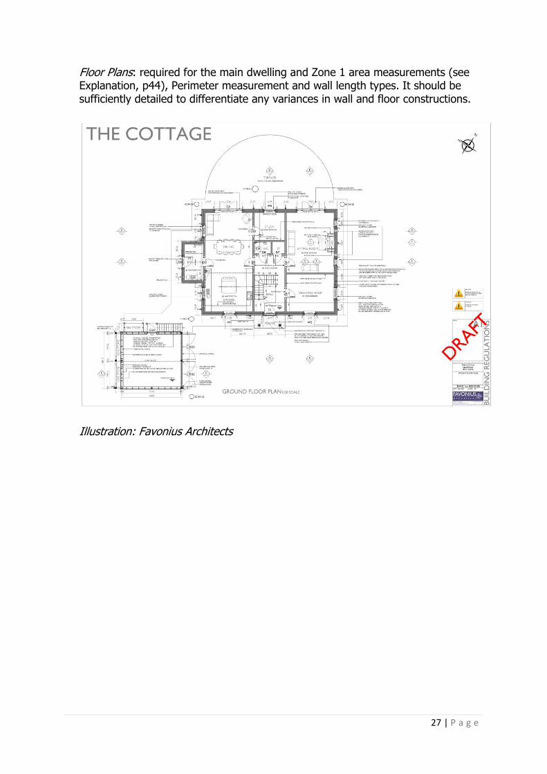
Floor Plans: required for the main dwelling and Zone 1 area measurements (see Explanation, p44), Perimeter measurement and wall length types. It should be sufficiently detailed to differentiate any variances in wall and floor constructions.
Illustration: Favonius Architects

28 | P a g e
Elevations: required to measure openings (if a full window/door schedule is unavailable), measure overshading and to check orientation.
Illustration: Favonius Architects

29 | P a g e
Sections: required to measure storey heights and, in particular, identify where the roof insulation is at rafter level, and where there are dormers or other roof protrusions. Ideally, both cross and longitudinal section drawings will be included, and if dormers or other protrusions are present, cross sections through these as well. It is almost impossible to provide an accurate calculation without section drawings, unless the dwelling is insulated at ceiling level only, and then only if the floor levels are clearly marked on elevation drawings.
Illustration: Favonius Architecture

30 | P a g e
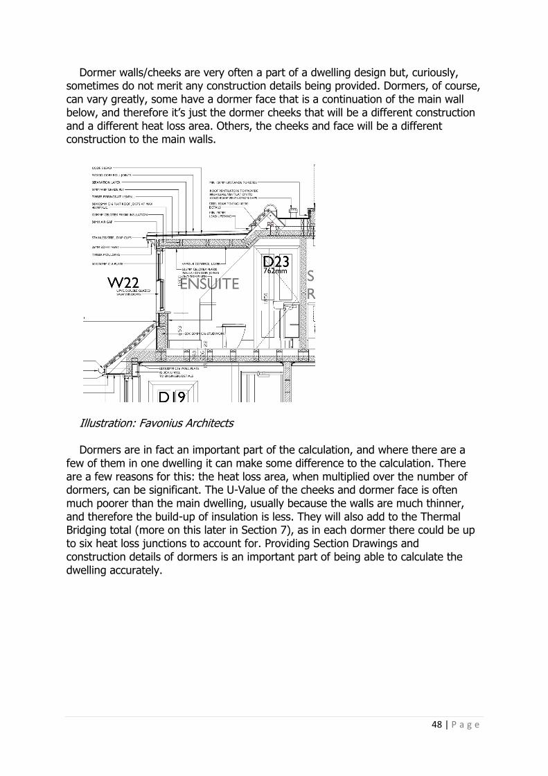
Details Drawings: these are required for all heat loss floors, external walls, party walls, sheltered walls and floors (e.g. from the dwelling to a garage) and all heat loss roofs. Often the main elements are provided, but elements such as dormer cheeks, dormer roofs, walls and floors adjacent to garages etc are not. These are all heat loss elements and as such will require a calculated U-Value for each of them.
Illustration: Batterham Matthews Architects Finally, to be able to measure from the drawings, either a dimension or a scale
bar must be included.

31 | P a g e
Measurement Conventions and What is Included The convention when measuring floor plans for SAP is to take internal measurements, following the line of the thermal envelope, i.e. the line of the insulation. It is vital, therefore, that not only are floor plans provided, but also enough sections so that it’s clearly seen how the insulation line flows throughout roof spaces and any perturbations such as dormers.
Zone 1 in a dwelling: this is the living area, and the area must be measured separately because the SAP software assumes this area is heated to 21 degrees, unlike the rest of the dwelling, which is at 18 degrees. Zone 1 is normally the living room or lounge and includes all areas that are not separated from it by walls or doors. If there is an open-plan living room, dining and kitchen it would include all these areas. If there are stairs in the living room, only the ground floor area of these is taken into account, and if there are storage spaces within the living room, these too are included. Zone 1 is covered in a little more details in Section 3: Floors.
Areas of the dwelling that should be included in addition to the main floor areas
are as follows: • Porches: if heated or not thermally separated, or within the main dwelling
envelope. They are only excluded if external to the main envelope, thermally separated and unheated
• Conservatories: only included if not thermally separated from the dwelling • Store rooms and utility rooms: included if directly accessible from the
dwelling; if they are unheated and accessed from outside, they are excluded • Basements: included if they are accessed by fixed staircase and are either
heated by fixed emitters or are open to the rest of the dwelling • Garages: only if heated by the main dwelling heating system. • Attics: only included if they are accessed by a fixed staircase
SAP Input Fields: General Information The SAP input fields are explained in detail over the next sections of this book. As with any software, the better the input, the better the output. No more is this so relevant than in the SAP software. If you want your dwelling to pass building Regulations and, perhaps more importantly, reflect the true energy use and CO2 emissions from that dwelling, then the more detailed input that can be provided, the more worthwhile it will be. At times, however, it may be necessary to use the SAP Default Values. This can happen throughout the design process where a calculation is carried out in the early stages and the full design detail is unknown. The impact of SAP Default figures in some fields can be fairly negligible, whilst others will almost certainly result in a fail overall. Which fields this applies to will be explained as appropriate in each section below.

32 | P a g e
SAP and Building Regulations Compliance This is covered fully in Part Three. For now, there are two criteria to have an understanding of, as it is these that are affected by all that follows. Part L1A – Criterion 1 – Achieving the TER and the TFEE The calculated CO2 emission rate for the dwelling (The DER: Dwelling Emission Rate) must not be greater than the target (TER: Target Emission Rate); and the DFEE (Dwelling Fabric Energy Efficiency Standard) must not be greater than the TFEE (Target Fabric Energy Efficiency). These two are the main requirements of Part L1A and are mandatory, therefore a SAP calculation is required to meet this criterion.
Throughout all the following sections, the SAP input is discussed with regards to its impact on both of these two criteria – the DER and the DFEE.
Structure of SAP Input: Each Section in SAP
Section 1: Job Details Section 2: Dwelling Section 3: Heat Loss Floors Section 4: Heat Loss Walls Section 5: Heat Loss Roofs Section 6: Openings Section 7: Thermal Bridges Section 8: Ventilation Section 9: Space Heating Section 10: Water Heating Section 11: Renewables Section 12: Other
Section 1: Job Details In this first section the input is very basic, as follows:
• Assessor, Client and Development name
• The Dwelling Type: House, Bungalow etc • Dwelling Category: either new build or existing build • Address and postcode The postcode will determine which Building Regulations apply to the calculation,
either England, Wales, Scotland or Northern Ireland, the software automatically reconfiguring to meet the requirements of each as appropriate.
It’s surprising how many assessments I get to start where the full address and
postcode are not provided. These are important, not only because it simply identifies the dwelling correctly, and will eventually appear on any certificates, but most importantly the postcode identifies the climate data that will be used. This regional climate data is used for the summer overheating risk assessment and cooling calculation, although it doesn’t affect the Building Regulations compliance or SAP rating.

33 | P a g e
Section 2: Dwelling
Dwelling Type Dwelling Type: either House, Bungalow, Flat or Maisonette.
This is used by the EPC and as such must be a correct description (according to the SAP definitions of each). An EPC produced with an incorrect dwelling type would fail an audit process.
Built Form Here the assessor can select Detached, Semi Detached, Mid Terrace, End Terrace, or Enclosed Mid or Enclosed End Terrace.
Like the dwelling type this is also displayed on the EPC, and is used in setting the Fabric Energy Efficiency Standard.
For Flats and Maisonettes only, these can be further identified by their floor
position, e.g. Ground Floor, Mid Floor or Top Floor. Maisonettes are identified where there is a flat over two or more levels and the
entrance door is clearly on the ground level. Year Built I tend to always default to the current year that the assessment is started. Electricity Tariff There are a number of tariffs from which to choose, the most used being Standard, i.e. just one. However, where it is known if there is to be a dual tariff, it is usually best when the DHW is on an immersion only and a dual core cylinder is being installed. The two tariffs being the difference between night and day tariffs, although the hours split between these can vary, as indicated by the options available, as follows:
• Standard/normal domestic electricity tariff with no off-peak element • Off-peak seven hours: allows for a single overnight period of at least seven
hours of off-peak electricity for space and water heating. An on-peak rate is charged for the rest of the day
• Off-peak ten hours: divides the off-peak hours for space and water heating into three periods (typically five hours at night, three hours in the afternoon and two hours in the evening). Lights and appliances will use the standard tariff. This tariff is only available in certain areas

34 | P a g e
• Off-peak eighteen hours: this is intended for use with electric CPSUs that have enough energy storage to provide heat for up to two hours without any electricity supply. Low-rate-price electricity is available for eighteen hours per day with interruption totalling six hours per day (with each interruption being no more than two hours). This tariff is only available in certain areas
• Twenty-four hour: this tariff is used only with whole-house, storage-based electric heating systems that are designed for about 60% storage and 40% direct-acting heaters. It is only available in certain areas
For homes that are electrically heated the above options can be significant. The
different options relate to the different times that an off-peak rate is available as well as the electricity unit prices. SAP will use the appropriate rates in the calculation of both the energy ratings and the running costs and also adjusts the ratio of on-peak to off-peak fuel use to take account of the different charging periods.
Although covered later under Heating and Hot Water, it should be said that if an
immersion-only DHW system is chosen, invariably fuelled by electricity, under the tariff options above, the resulting DER will be much higher than if the DHW were heated from the same source as the main heating system, e.g. a gas boiler. For this reason, most developments avoid heating hot water by an immersion only, and instead will use it solely for back-up purposes.
Summer Overheating: Yes or No? For a Building Regulations’ assessment this is always required, as it looks at compliance with Criterion Three of Part L1A, however this does not affect the DER. More on this in a later section.
Thermal Mass Parameter (TMP)
This is one of the only inputs in this first section that can have a significant effect
on the DER rating. 'Thermal mass' describes a material's capacity to absorb, store and release heat.
For example, water and concrete have a high capacity to store heat and are referred to as 'high thermal mass' materials. Insulation foam, by contrast, has very little heat storage capacity and is referred to as having 'low thermal mass'.
A common analogy is thermal mass as a kind of thermal battery. When heat is applied (to a limit) by radiation or warmer adjoining air, the battery charges up until which time it becomes fully charged. It discharges when heat starts to flow out as the adjoining air space becomes relatively cooler.

35 | P a g e
Thermal Mass is determined by being either Low, Medium, High, or User Defined. • Low is a TMP of up to 100 Kj/m2K
• Medium is a TMP between 101 and 250 Kj/m2K • High is a TMP between 251 and 450 Kj/m2K BRE SAP 2012 document Table 1e and Table 1f provides full details of how to
calculate the TMP if a User-Defined value is to be used. SAP Conventions 20 October 2015 (v6.0) Table 2 Thermal Mass for the Whole
Dwelling, details the types of constructions that can be referenced when determining if a dwelling is to use the Default Low, Medium or High Values.
As a rough indicator: • Timber frame is usually Low • It is Medium if there are dense blocks in the external or partition walls • It is High if at least two of the external walls, internal partition wall or party
wall have dense blocks • Internal insulation makes it Low, irrespective of the construction BRE SAP 2012 document Table 3, below, shows the basic constructions that
indicate what level of Thermal Mass should be used in the calculation if a full calculation is not undertaken.
Table 3: Indicative Constructions to Determine the Thermal Mass of a Dwelling

36 | P a g e
The effect of changing TMP on the DER. Using the test dwellings, the variations in DER are as follows:
Table 4: Test Dwellings – Difference in DER Compared to the TER by Changing the Thermal Mass Parameter (TMP)
Thermal
Mass Parameter
(TMP)
Detached
TER 18.46
Detached
TER 15.73
Semi
TER 14.29
End
Terr TER
18.76
Mid
Terr TER
17.60
GF
Flat TER
16.31
Mid
Flat TER
14.67
Top
Flat TER
16.66
DER
Low (up to
100 Kj/m2K)
16.94 14.16 13.27 17.85 16.91 14.99 14.09 15.34
Medium (up to 250 Kj/m2K)
18.29 15.24 14.24 18.45 17.29 15.39 14.37 15.72
High (up to 450 Kj/m2K)
18.98 15.78 14.71 18.81 17.53 15.62 14.55 15.94
Table 5: Test Dwellings – Difference in DFEE Compared to the TFEE by Changing the Thermal Mass Parameter (TMP)
Thermal
Mass Parameter
(TMP)
Detached
TFEE 62.9
Detached
TFEE 55.6
Semi
TFEE 49.4
End
Terr TFEE
51.2
Mid
Terr TFEE
45.2
GF
Flat TFEE
44.6
Mid
Flat TFEE
37.3
Top
Flat TFEE
45.1
DFEE
Low (up to
100 kj/m2K)
56.7 48.5 45.1 47.9 43.0 39.3 35.6 39.9
Medium (up to 250 kj/m2K)
60.6 51.6 47.8 49.8 44.00 39.9 35.9 40.4
High (up to
450 kj/m2K)
62.7 53.2 49.1 51.0 44.8 40.5 36.4 41.0

37 | P a g e
The variance in DER and DFEE will differ between dwellings as the area of the thermal elements increases/decreases, the build-up of those elements changes, and whatever the total floor area is. In the examples above, only changing to High Thermal Mass results in a higher DER than the TER in some of the dwellings. The DFEE is changed but not significantly.
The conclusion from the above could be that if a High Thermal Mass dwelling is
desired, a calculated TMP would be worth considering to ensure the correct figure is input into the SAP and the DER is not compromised any further than it may have been if the standard 450 Kj/m2K was used. This does not mean that a High Thermal Mass will automatically fail. The DER is increased, but flexibility within a calculation allows for other criteria to be improved, for example lower U-Values, to compensate for this. The next round of Building Regulations’ changes could see the requirement for TMP calculations to be carried out on all dwellings for SAP. This was a proposal for the last SAP/Part L changes in 2013 but was dropped at the time.
The calculation is completed over all the layers of the construction element,
starting at the inside surface and stopping at whichever of these conditions occurs first (including its occurrence part-way through a layer):
• Half way through the construction • An insulating layer • A maximum thickness of 100mm
The calculation is as follows: 𝑇𝑀𝑃 =sum k x A
𝑇𝐹𝐴
Where: k = Heat Capacity of Thermal Element A = Area of Thermal Element TFA = Total Floor Area Following the SAP evidence requirements for the final Building Control submission
documents and EPC, the drawings/specification should show the construction of the thermal elements and internal walls and floors, to demonstrate how the chosen TMP has been determined. If a calculated TMP has been input, supporting calculations must be available.
It can be: a. calculated from the areas and kappa values of each element, as given above,
where the kappa values are from SAP Table 1e or calculated following the guidelines in SAP Table 1e, or:
b. entered into the software as a TMP value that has been calculated, as in a. (for example, using a spreadsheet), or:
c. treated as being Low, Medium or High using the global values of 100, 250 or 450 kJ/m²K given in SAP 2012 Table 1f (shown in Table 3, above).

38 | P a g e
Conservatories Thermally Separated Heated Conservatory
Graphic: Merstham Glass
A Conservatory is included in calculations if:
• It is not thermally separated from main dwelling, or • It is heated by the dwelling's main heating system (England), or heated by
fixed heaters (Wales) A conservatory is usually defined as an extension to a dwelling that has not less
than three-quarters of its roof area and not less than half of its external wall area glazed.
However, if a highly glazed structure attached to a dwelling is not thermally
separated it is not a conservatory for the purposes of the SAP. In such a case it should be treated as an integral part of the dwelling, with the glazed part of the structure input in the same way as any other glazed area.
If it is thermally separated, although ignored by the calculation, this needs to be
identified as it is included in the EPC. It does not have any influence on the DER or U-Values in this area; it is treated as though it doesn’t exist.
Thermal separation between a dwelling and a conservatory means that: • The walls, floors, windows and doors between a dwelling and a conservatory
have U-Values similar to those of the other exposed elements • The windows or doors between a dwelling and a conservatory have similar
draught-stripping provisions as the windows and external doors elsewhere in the dwelling

39 | P a g e
Essentially, if a conservatory is thermally separated from the rest of the dwelling it is ignored; however, if any highly glazed structure is open to the rest of the heated dwelling, it is included in the calculation.
Location The Degree Day location is identified here, from the postcode entered earlier. This is used to determine the Degree Days and the level of solar insolation affecting the solar gains. The height above sea level and wind speed are automatically selected based upon the above, all of these three inputs can be entered manually although there is little advantage in doing so. The Terrain is entered as either Rural, Low Rise or Urban and is only used in the EPC recommendations to determine if a wind turbine is appropriate.
Sheltered Sides This is between 0 and 4, and refers to the number of sides on which the dwelling is sheltered from the wind by other buildings, trees or hedges etc. Zero is entered if unknown, e.g. if a site plan is unavailable, or if the site plan does not show other buildings etc that may offer sheltering.
To determine if a dwelling is sheltered or not: The obstacle that is providing the shelter must be at least as high as the dwelling,
and the dwelling must be less than five times the height of the obstacle. This can have a small impact on the DER. In Tables 6 and 7, the test dwellings
DER and DFEE vary as follows, depending on the number of sheltered sides. However, this is not really a design consideration per se; it is what it is. Having said that, if the shelter provides external shading this can have significant impact on reducing summer overheating and winter solar gain, so although not so important a consideration for the SAP calculation, external sheltering can be important when considering seasonal temperatures.
Table 6: Test Dwellings – DER/TER Percentage Variance Depending on the Number of Sheltered Sides, to Dwelling Type
Number of
Sheltered Sides
Detached
Detached
Semi
End
Terr
Mid
Terr
GF
Flat
Mid
Flat
Top
Flat
DER Percentage Variance
0 -3.13 -1.01 n/a n/a n/a -5.66 -2.14 -5.72
1 -3.01 -0.91 -0.35 -1.69 n/a -5.65 -2.09 -5.65
2 -2.97 -0.87 -0.85 -1.65 -1.76 -5.64 -2.04 -5.64
3 -2.93 -0.76 -1.21 -1.56 -1.72 -5.62 -1.99 -5.63
4 -2.88 -0.71 -1.57 -1.51 -1.67 -5.54 -1.94 -5.61
The TER as well as the DER changes, depending on the number of sheltered sides

40 | P a g e
Table 7: Test Dwellings – DFEE /TFEE Percentage Variance Depending on the Number of Sheltered Sides, to Dwelling Type
Number of
Sheltered Sides
Detached
Detached
Semi
End
Terr
Mid
Terr
GF
Flat
Mid
Flat
Top
Flat
DFEE Percentage Variance
0 -7.2 -3.7 n/a n/a n/a -10.6 -3.9 -10.5
1 -7.1 -3.6 -3.2 -2.9 n/a -10.4 -3.7 -10.5
2 -7.0 -3.5 -3.9 -2.7 -2.7 -10.5 -3.8 -10.4
3 -7.1 -3.4 -4.6 -2.6 -2.2 -10.5 -3.6 -10.4
4 -6.8 -3.3 -5.2 -2.4 -2.1 -10.4 -3.3 -10.3
The TFEE as well as the DFEE changes, depending on the number of sheltered sides As can be seen above, the DER variance can be as little as -0.35% and a more
significant -5.72%, depending on the dwelling type. The DFEE variance can be more significant, ranging from -2.1% to -10.6%, again dependant on dwelling type.
Orientation The orientation of the dwelling does have an impact on the DER. It is also linked from this input screen to the Openings, Solar Thermal and Solar PV inputs. Changing the orientation here in effect rotates the dwelling, taking with it the locations of the openings and any solar panels.
The front of the dwelling is usually determined by the orientation of the main entrance door. In flats, where the entrance is from a communal corridor, it makes little difference but does lead to consistency in identifying the placement of dwellings.
In the test dwellings, which had Openings at both North and South facing, the
front was determined here as North. Table 8, below, shows the effect of rotating the dwelling from North, and the effect on the DER. The direction the dwelling faces in itself is of little consequence. It is, however, the Openings and any Solar System orientation that influences the DER. By definition, careful siting of the dwelling with regards its orientation, and therefore the orientation of the Openings and Solar system, is a consideration.
Table 8: Test Dwellings – DER/TER Percentage Variance Depending on Dwelling Orientation, to Dwelling Type
Orientation Detached
Detached
Semi
End
Terr
Mid
Terr
GF
Flat
Mid
Flat
Top
Flat
DER Percentage Variance
North -2.94 -0.62 -0.07 -1.65 -1.76 -5.64 -2.04 -5.64
North East -3.03 -0.46 -0.14 -1.69 -1.80 -5.66 -2.09 -5.66
East -3.17 -0.41 -0.35 -1.82 -1.94 -5.65 -2.13 -5.70
South East -3.16 -0.51 -0.42 -1.77 -1.88 -5.64 -2.11 -5.69
South -3.12 -0.67 -0.35 -1.72 -1.83 -5.62 -2.17 -5.67
South West -3.11 -0.82 -0.42 -1.77 -1.88 -5.64 -2.11 -5.69
West -3.13 -0.87 -0.35 -1.82 -1.94 -5.65 -2.13 -5.70
North West -3.1 -0.77 -0.14 -1.69 -1.80- -5.66 -2.09 -5.66

41 | P a g e
Table 9: Test Dwellings – DFEE/TFEE Percentage Variance Depending on Dwelling Orientation, to Dwelling Type
Number of
Sheltered Sides
Detache
d
Detache
d
Sem
i
End
Terr
Mid
Terr
GF
Flat
Mid
Flat
Top
Flat
DFEE Percentage Variance
North -7.1 -3.0 -2.6 -2.7 -2.7 -10.5 -3.8 -10.4
North East -7.1 -2.8 -2.9 -3.1 -2.8 -10.6 -3.7 -10.5
East -7.3 -2.6 -3.2 -3.3 -3.1 -10.5 -4.1 -10.4
South East -7.3 -2.9 -3.2 -3.3 -3.1 -10.5 -4.0 -10.6
South -7.2 -3.1 -3.0 -3.2 -3.0 -10.5 -4.0 -10.6
South West -7.2 -3.4 -3.2 -3.3 -3.1 -10.5 -4.0 -10.6
West -7.2 -3.5 -3.2 -3.3 -3.1 -10.5 -4.1 -10.4
North West -7.0 -3.2 -2.9 -3.1 -2.8 -10.6 -3.7 -10.5
Both the TER and TFEE as well as the DER and DFEE change upon change of orientation.
In addition, in all the above dwellings, the change in orientation did not show a
summer overheating problem, but this may not always be so.
Storeys The final input is the area and average height of each storey of the dwelling. These are used in the volume calculation for the dwelling and do change the DER. This is because the greater the volume, the greater the heat losses, and therefore the greater the heating requirement, resulting in higher CO2 emissions.
The area and average storey height obviously has an effect on the DER, and is one of the first calculations I carry out in the SAP calculation process. The Table below shows the effect of changes to a floor area in relation to its average height, on the resulting DER. The Table uses one of the test detached dwellings.
Table 10: Test Dwelling – The Effect of Floor Area and Dwelling Storey Height on the DER
Floor Area
m2
DER at Storey
Height of 2.4m
DER at Storey
Height of 2.5m
DER at Storey
Height of 2.6m
10 23.03 23.08 23.13
15 21.36 21.43 21.49
20 20.04 20.13 20.21
25 18.98 19.08 19.17
30 18.10 18.21 18.32
35 17.35 17.47 17.59
100 12.55 12.74 12.93
As can be seen, the DER decreases as the floor area increases, due to the
reduced surface-to-volume ratio, if the same average floor height is used. However, the DER then increases as the floor height increases, or as the surface area is increased. The higher the floor area in relation to its average floor height has a greater impact on the DER than changing the average floor height in relation to its area.
42 | P a g e
Summary of Section 2 Of all the input required in the initial Dwelling set up, very little affects the DER SAP calculation. Those that do are as follows:
Thermal Mass Parameter: I find that the Thermal Mass Parameter has the greatest impact on the final DER result. A change from a dense block to a lightweight block can often be the difference between a pass and a fail overall. When it comes to assessing an As-Built SAP, the DER is very close to the TER.
Sheltered Sides: the DER impact is fairly negligible, and although this input needs
to be correct, the dwelling design/site position shouldn’t be too concerned with this. However, it is an important consideration in terms of summer overheating etc.
Orientation: the DER impact can be significant, although it’s not here that this is
accounted for, but in the orientation of the Openings and for any Solar Thermal Panels that are included. It is also of vital importance when designing for unwanted summer overheating and maximising winter solar gain. Although summer overheating is assessed within SAP, better tools (i.e. other thermal modelling software tools) are designed specifically for the purpose. If there are any concerns regarding overheating, it should be designed to be minimised outside of the SAP calculation and the results, within the realms of the SAP assessment, input accordingly.
Storeys: this also affects the DER. It has been included here because it must be
calculated correctly, but rare would it be that a dwelling is designed around specific floor area to floor height ratio.

43 | P a g e
Section 3: Heat Loss Floors
Illustration: Batterham Matthews Architects Here, all heat loss floors are entered in to the software. This is not just the ground floor, but all those other heat loss floors on upper storeys, for example overhangs, floors over unheated corridors and garages etc. It’s surprising how many of these are missed or considered less important than the obvious heat loss to the ground, but they all need to be accounted for. If the floor is semi exposed, i.e. to a corridor or garage, and is less than 10% of the rest of that same floor, it can be ignored.
Internal floors between heated storeys are not heat loss floors, so will be ignored from the calculation.
Input Required The storey location, and the type of floor, e.g. Basement, Ground or Upper. Information is taken from the floor plans and sections.
Floor Construction: Solid floor, Suspended not timber (usually beam and block), Suspended Timber Sealed and Suspended Timber not sealed. The difference between these last two will affect the ventilation loss from the dwelling, as there is obviously ventilation under the floor, although it doesn’t affect the DER or DFEE figure.
Floor Area m2: this is the total floor area for the type and location of a heat loss
floor. A new entry is made for each subsequent heat loss floor.

44 | P a g e
Zone 1: if there is any part of Zone 1 that is part of a heat loss floor, its area needs to be identified. If any part of Zone 1 floor area is not connected to a heat loss floor, this needs to be entered separately.
Obviously the larger the Zone 1 heat loss floor area, the worse the DER figures
are, due to the higher internal temperature. This has no effect on the DFEE. This is shown in Table 11, below. Interestingly, if there is no heat loss floor to Zone 1, the m2 area of Zone 1 is entered as no heat loss floor and the DER is the same as if there is a heat loss floor. The DER only changes when the Zone 1 area is increased/decreased.
Table 11: Test Dwelling – The Effect of Zone 1 Area on the DER
Total Floor Area m2 Zone 1 Area Percentage of Total
Floor Area
DER
107.08 0m2 0 18.29
107.08 10m2 9.3 18.09
107.08 20m2 18.6 18.32
107.08 30m2 28.0 18.56
107.08 18.65 (Actual) 17.4 18.29
If the Zone 1 floor is not heat loss, for example, if it was on the first floor of the
test dwelling, the DER is exactly the same as above. The important factor, therefore, is not where the Zone 1 floor is, in terms of heat loss, but the area and the U-Value attributed to the floor of which it is a part.
Swimming Pool: if a swimming pool is present, the basin is in effect ignored;
however, it is still a heat loss floor, and in the SAP calculation the U-Value of the floor surrounding the pool basin is taken for the whole floor area of the pool room.
U-Value W/m2K: the calculated U-Value for each different heat loss floor. Full details of how to complete U-Value calculations can be found by consulting
the BRE’s Conventions for U-Value Calculations; however, there are a few items worth mentioning here in relation to heat loss floors.
For all U-Value calculations, not just floors, the origin of the lambda value W/m. K
should be from a verified source, e.g. a BBA Certificate. When calculating U-Values, the thickness (mm) and thermal conductivity (lambda
W/m. K) of each layer is required. In addition, to calculate the U-Value, the heat loss floor area (m2) and heat loss perimeter (m) are also required from the floor plans. In addition, the wall thickness (mm) is also required.
In heated basement floors, the total depth (m) of the basement is required; and
in unheated basements, in addition to the above, the height above ground (m), the U-Value of the walls above, the U-Value of the floor above and the external walls, plus the air-change rate are required.

45 | P a g e
For suspended floors, the depth of the space below ground, the floor height above ground, and the U-Value of the external wall above ground are required.
As mentioned, the U-Value the heat loss floor will have has an impact on the DER
and DFEE figures, which can be considerable. Therefore, the more accurate the information that can be entered into the U-Value calculation the better, most of which should be available to see from a Section and Plan Drawing. Table 12: Test Dwellings – The Effect on the DER/DFEE of Ground Floor U-Values of the Notional U-
Values Compared to Part L Maximum U-Values
Dwelling
Type
TER
Notional
U-Value
(0.13 W/m2K)
DER
Part L
Max. U-
Value (0.25
W/m2K) DER
TFEE
Notional
DFEE
Part L
Max.
DFEE
Detached 15.73 15.24 15.90 55.6 51.6 55.0 Semi Detached
14.29 14.24 14.75 49.4 47.8 50.3
End Terrace 18.76 18.45 19.14 51.2 49.8 53.2 Detached 18.46 18.30 19.00 62.9 60.7 64.3 Mid Terrace 17.6 17.29 17.99 45.2 44.0 47.5 Top Floor
Flat 16.66 n/a n/a 45.1 n/a n/a
Ground Floor Flat
16.31 15.39 16.09 44.6 39.9 43.4
Mid Floor
Flat 14.67 n/a n/a 37.3 n/a n/a
As can be seen from Table 12, above, obviously the difference between the two
U-Values has an immediate impact on the resulting DER/DFEE. On average, across these dwellings there is a 4% DER variance between Notional and Part L maximum; and, for the DFEE, a 6% variance. It highlights the need to be designing to a figure as near as possible to the Notional, rather than to the Part L Limiting Maximum U-Value.
SAP Evidence Requirements For the final Building Control submission documents and EPC, the drawings/specification must show the construction of the thermal elements, and U-Value calculations (U-Value calculation data sheet including construction layers [materials, thickness and thermal properties] and U-Value corrections) must be available.
SAP assessors must establish the specification of the construction for each element and must satisfy themselves that the U-Values used in the calculation are correct.
Acceptable routes are: • Calculation provided by a person accredited for U-Value calculations • Calculation undertaken by the assessor • Calculation provided by another party and checked by the assessor

46 | P a g e
In some cases, the calculation may depend on other pre-calculated results; in
those cases, the sources of the data used must be available. For example, a suspended floor where the thermal resistance of the floor deck has been calculated by numerical modelling. Building Regulations and the Notional Building The maximum U-Value for a ground floor in Part L1A is 0.25 W/m2K. The Notional/Model Dwelling used in the SAP calculation, and which informs the TER and TFEE result, is a U-Value of 0.13 W/m2K. This does not mean that all heat loss floors must be 0.13 W/m2K, but the area weighted average of each heat loss floor should be as near this as possible if a pass is to be achieved overall, in particular the DFEE figure.
Summary of Section 3 In reality, the whole of the input here will affect the DER and DFEE figures. The key points are as follows:
Provide detailed floor plans and section drawings, plus any detail drawings, of each heat loss floor. Include all floors that are heat loss, not just the ground floor (or basement floor).
Ensure thickness and type of materials are provided so that accurate U-Value
calculations can be carried out. The heat loss floor area combined with heat loss perimeter, and the thermal
resistance of materials used in the floor will determine the U-Value. The U-Value and the heat loss floor area will affect the DER and DFEE figure and,
by a small margin, the Zone 1 area will affect these too. Designing to a U-Value as near to the Notional of 0.13 W/m2K will be beneficial to
achieving the required DER/DFEE to meet the TER/TFEE.

47 | P a g e
Section 4: Heat Loss Walls
Illustration: Batterham Matthews Architects The input for walls follows in a very similar way to heat loss floors. All heat loss walls are included in the calculation.
Input Required Description of the wall: usually Wall Type from architect’s drawings.
Type: External, Basement, Sheltered or Party. If the dwelling type in Section 1 has been selected as Terrace or Semi Detached, the software assumes a Party Wall will be present.
Construction: Stone, Brick, Cavity, Timber, System Build, Curtain. None of the above will affect the results. However, they do need to be correct for
both the Building Regulations’ compliance document and the EPC. Total area: this is the total area of each different wall type. Any opening area
included in this total area; the openings being subtracted when they are entered into the software as they are assigned to a particular wall.
Gable walls are included when the insulation for the roof is at rafter level. If the
insulation is at ceiling level and therefore the roof a cold space, they would be ignored.
48 | P a g e
Dormer walls/cheeks are very often a part of a dwelling design but, curiously, sometimes do not merit any construction details being provided. Dormers, of course, can vary greatly, some have a dormer face that is a continuation of the main wall below, and therefore it’s just the dormer cheeks that will be a different construction and a different heat loss area. Others, the cheeks and face will be a different construction to the main walls.
Illustration: Favonius Architects
Dormers are in fact an important part of the calculation, and where there are a few of them in one dwelling it can make some difference to the calculation. There are a few reasons for this: the heat loss area, when multiplied over the number of dormers, can be significant. The U-Value of the cheeks and dormer face is often much poorer than the main dwelling, usually because the walls are much thinner, and therefore the build-up of insulation is less. They will also add to the Thermal Bridging total (more on this later in Section 7), as in each dormer there could be up to six heat loss junctions to account for. Providing Section Drawings and construction details of dormers is an important part of being able to calculate the dwelling accurately.

49 | P a g e
Party Walls
Since the 2010 Regulations, Party Walls have been deemed to be heat loss walls. In Party Walls the U-Value is based on the heat loss caused by air movement in the cavity, not the thermal resistance of the materials of the party wall. Therefore, the way to improve the U-Value is to restrict or prevent air movement within a cavity.
U-Value calculations are not carried out, instead there are four options in the software to choose from:
• Solid: this will have a heat loss of zero • Fully filled cavity with sealed edges: this too will have a heat loss of zero. To
qualify as fully filled, the cavity must be completely fully filled with insulation, including in a timber frame. If there are two walls fully filled but with a gap in-between, this is not fully filled. To be sealed, the wall must be sealed at both top and bottom, and along its height
• Unfilled with sealed edges: this will have a U-Value of 0.2 W/m2K. The sealing should be as described above
• Unfilled with unsealed edges: this will have a U-Value of 0.5 W/m2K Robust Details supply a number of construction details that satisfy the different
methods of filling Party Walls to achieve a zero U-Value and comply with both Building Regulations Part E and Part L.

50 | P a g e
The choice of Party Wall will affect the DER and DFEE, using one of the test detached dwellings, as the following Table shows:
Table 13: Test Dwelling (Mid Terrace) – The Effect on the DER and DFEE with Different Party Wall Constructions
Party Wall
Type
U-Value TER DER TFEE DFEE
Solid 0.0 W/m2K 17.60 17.29 45.2 44.00 Fully filled cavity
with sealed edges
0.0 W/m2K 17.60 17.29 45.2 44.00
Unfilled with
sealed edges
0.2 W/m2K 17.60 19.44 45.2 54.7
Unfilled with
unsealed edges
0.5 W/m2K 17.60 22.53 45.2 70.3
Table 13, above, highlights the effect the Party Wall U-Value can have on the
DER/DFEE, particularly in a Mid Terrace House or a flat where the proportion of Party Walls could be much greater than external heat loss walls.
SAP Evidence requirements: Party Wall U-Values Sealing
• Specification on plans of location of edge sealing, including edge sealing detail, e.g. drawing or named system, or:
• Written confirmation from builder that sealing has been done Filling and Sealing
• Confirmation that Mineral Wool Insulation Manufacturers Association (MIMA) Guidance 1 has been adhered to, or:
• Written confirmation from builder that filling and sealing has been done Curtain Walling: increasingly specified as an option for dwellings, these are
modelled in SAP in the same way as for any other external wall. However, there are some important differences that will affect the resulting DER.
Establishing the correct U-Value for the whole wall is important. This should
include allowances for linear Thermal Bridging associated with the glazing surrounds and heat losses from mullions, spandrels and transoms in the curtain walling.
Normal linear Thermal Bridging lengths entered in the Thermal Bridging input is
also changed when curtain walling is input, with the lengths entered as zero but the psi values remaining in place. There is more detail on Thermal Bridging in Section 7, but suffice to say here, if the Thermal Bridging is input incorrectly because the curtain walling specification is misunderstood, the effect on the overall result can be serious.
Sheltered Walls: for example, a wall to a garage or unheated corridors for flats.
The heat loss from these is lower than the corresponding external walls, due to the sheltering effect of the external wall beyond, but these are still included within the calculation as a separate wall.

51 | P a g e
U-Value W/m2K: the calculated U-Value for each different heat loss wall. The U-Values are calculated following the same conventions as for heat loss floors
and roofs from BRE’s Conventions for U-Value Calculations. There are a few points worth mentioning here in regard to wall U-Value
calculations. It’s not just the insulation type and thickness of it that will make a considerable difference, although from the information I am sometimes provided with you would think this is the only important input!
In a cavity wall using blocks, the variance in conductivity of the block ranges from
a Solar block at 0.11 W/m. K, to a heavy block at 1.13 W/m. K, an enormous difference that will affect the final U-Value result. Corrections for steel wall ties and air space emissivity will also make a difference, and of course the multitude of wall insulation types available and their comparative thermal performance is vast.
Specifying is one thing, communicating this is another. To specify ‘Celotex’ for
example, when there are three or four different insulations for cavity wall is not very helpful; better would be to specify the Celotex specific product. Likewise, specifying ‘Dritherm’, rather than Dritherm 32, 34 or 37, can allow mistakes in the U-Value calculation and, therefore, in the final SAP result.
A U-Value calculation for a full-fill cavity wall using Dritherm, for example, would
be for: • Dritherm 32–0.24 W/m2K • Dritherm 34–0.25 W/m2K • Dritherm 37–0.26 W/m2K Not a huge difference you may think but when trying to achieve the DFEE figure
when the Notional external wall is 0.18 W/m2K, every little will help! Wall ties: these are also accounted for as one of the corrections in the U-Value
calculation. If used in a timber-framed wall they are ignored altogether. It’s only for masonry walls where plastic or basalt wall ties are used, as long as the lambda value is below 1.0, they can also be ignored and no correction required. For normal stainless steel wall ties, a correction is made to the wall U-Value, the Default density of 2.5 per m2 is used, although this can be adjusted, and the cross-section area. (For cavities up to 150mm, 12.5 in mm2 is usually used; in a cavity over 150mm, 80.0 in mm2 is used.)
In effect, the differences in U-Values are not significant except where the
numbers per cross section are increased. In an example 100mm cavity, depending on storey height and exposure, the choice of wall tie could be between 3.5mm2 and 60mm2, the U-Value difference being 0.285 W/m2K and 0.3 W/m2K. Multiply this by the area of external wall and the resulting DER change could be significant.
As mentioned earlier in the floor section, the U-Value of the heat loss wall will also
have an impact on the DER and DFEE figures, which can be considerable, therefore

52 | P a g e
the more accurate the information that can be entered into the U-Value calculation the better, most of which should be available to see from a Section and Plan Drawing. Table 14: Test Dwellings – The Effect on the DER/DFEE of External Wall U-Values of the Notional U-
Values Compared to Part L Maximum U-Values
Dwelling Type
TER Notional U-Value
(0.18 W/m2K)
DER
Part L Max. U-
Value (0.30
W/m2K)
DER
TFEE Notional DFEE
Part L Max.
DFEE
Detached 15.73 15.24 16.56 55.6 51.6 58.3 Semi
Detached 14.29 14.24 15.27 49.4 47.8 53.0
End Terrace 18.76 18.45 19.94 51.2 49.8 57.2 Detached 18.46 18.30 19.65 62.9 60.7 67.6 Mid Terrace 17.6 17.29 18.09 45.2 44.0 48.0 Top Floor Flat
16.66 15.72 17.18 45.1 40.4 47.8
Ground
Floor Flat 16.31 15.39 16.95 44.6 39.9 47.8
Mid Floor
Flat 14.67 14.37 15.85 37.3 35.9 43.3
From Table 14, above, like the floor U-Values in Table 12, the difference between the two U-Values has an immediate impact on the resulting DER/DFEE, but even more so. On average across these dwellings, there is an 8% DER variance between Notional and Part L maximum, and for the DFEE a whopping 13% variance. Again, it highlights the need to be designing to a figure as near to the Notional as possible, rather than the Part L Limiting Maximum U-Value.
SAP Evidence Requirements For the final Building Control submission documents and EPC, the drawings/specification must show the construction of the thermal elements, and U-Value calculations (U-Value calculation data sheet including construction layers [materials, thickness and thermal properties] and U-Value corrections) must be available.
SAP assessors must establish the specification of the construction for each element and must satisfy themselves that the U-Values used in the calculation are correct.
Acceptable routes are: • Calculation provided by a person accredited for U-Value calculations
• Calculation undertaken by the assessor • Calculation provided by another party and checked by the assessor In some cases, the calculation may depend on other pre-calculated results; in
those cases, the sources of the data used must be available.

53 | P a g e
Building Regulations and the Notional Building The maximum U-Value for an External Wall in Part L1A is 0.30 W/m2K. The Notional Building used in the SAP calculation, and which informs the TER and TFEE result, is a U-Value of 0.18 W/m2K. This does not mean that all heat loss walls must be 0.18, but the area weighted average of each heat loss wall should be as near this as possible if a pass is to be achieved overall, in particular the DFEE figure. Summary of Section 4 It probably goes without saying that the external and other heat loss walls will make up the largest heat loss area of the dwelling, and usually more than the roof, so of course this is going to affect the end result enormously. So what are the key points to bear in mind, other than the larger the area the greater the heat loss, depending on how low the U-Value is?
Main external walls: specify the insulation and block type – both vary a great deal, even from one manufacturer like Celotex or Hanson. By doing so, a more accurate U-Value calculation will be produced.
Include all heat loss walls. Things such as sheltered walls to garages, unheated
loft spaces, unheated corridors in flats, for example, all need to be considered as they will affect the end result.
Party walls are important and vary in their U-Value depending on effective sealing
and insulation. If specifying Curtain Walls, it should be established how the U-Value has been
derived. U-Value calculations for walls are subject to numerous variances in input, all will
have an effect on the resulting U-Value and, therefore, the DER. Therefore, the more detailed the specification, the higher the likelihood of a more accurate U-Value.
Design U-Values should be as near as possible to the Notional U-Value of 0.18
W/m2K in order to meet the required DER/DFEE, which in turn will improve the TER/TFEE.

54 | P a g e
Section 5: Heat Loss Roofs
Illustration: Batterham Matthews Architects The final Building Elements section to be input is Roofs. All roofs should be entered into the calculation. This includes roofs such as terraces, entrance porches (if heated and open to the dwelling), dormers and roofs from basements where there is no building above. It often happens that I am given details for the main roof, but all these other areas are forgotten and yet collectively they may all be a significant heat loss area. Input Required Roof Description and Roof Construction: Pitched Rafters, Pitched Joists or Flat.
Area: the convention is to follow the line of insulation and identify all the different roof types and U-Values.
Mansard roofs, and other roofs where the angle of the roof slope is over 70
degrees, are treated in SAP as a heat loss wall. Therefore, in some instances, the roof area could be lower than the highest storey floor area.
U-Value: the overall roof U-Value is input. Calculating roof U-Values is
straightforward enough; there are a couple of things to note, however, which will affect the end result. This involves the various corrections that are required for roofs where the ceiling either does not follow the line of insulation, for example, in a roof insulated at rafter level with a flat ceiling. This U-Value will be worse than for a roof with no flat ceiling and open to the rafters, by as much as 0.03 W/m2 K in a normal construction of 150mm PIR between the rafters.
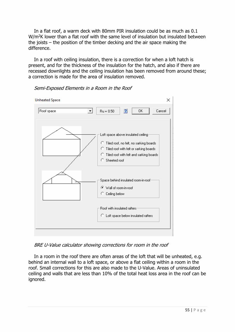
55 | P a g e
In a flat roof, a warm deck with 80mm PIR insulation could be as much as 0.1 W/m2K lower than a flat roof with the same level of insulation but insulated between the joists – the position of the timber decking and the air space making the difference.
In a roof with ceiling insulation, there is a correction for when a loft hatch is
present, and for the thickness of the insulation for the hatch, and also if there are recessed downlights and the ceiling insulation has been removed from around these; a correction is made for the area of insulation removed.
Semi-Exposed Elements in a Room in the Roof
BRE U-Value calculator showing corrections for room in the roof In a room in the roof there are often areas of the loft that will be unheated, e.g.
behind an internal wall to a loft space, or above a flat ceiling within a room in the roof. Small corrections for this are also made to the U-Value. Areas of uninsulated ceiling and walls that are less than 10% of the total heat loss area in the roof can be ignored.

56 | P a g e
Table 15: Test Dwellings: The Effect on the DER/DFEE of Roof U-Values of the Notional U-Values Compared to Part L Maximum U-Values
Dwelling
Type
TER Notional
U-Value (0.13 W/m2K) DER
Part L
Max. U-Value
(0.20 W/m2K)
DER
TFEE Notional
DFEE
Part L
Max. DFEE
Detached 15.73 15.24 15.63 55.6 51.6 53.6 Semi
Detached 14.29 14.24 14.58 49.4 47.8 49.5
End Terrace 18.76 18.45 18.86 51.2 49.8 51.8 Detached 18.46 18.30 18.76 62.9 60.7 63.0 Mid Terrace 17.6 17.29 17.7 45.2 44.0 46.0 Top Floor
Flat 16.66 15.72 16.24 45.1 40.4 43.1
Ground
Floor Flat* 16.31 15.39 15.44 44.6 39.9 40.2
Mid Floor Flat
14.67 n/a n/a 37.3 n/a n/a
* The Ground floor flat has a small 5m2 area of roof.
From Table 15, above, like the floor and wall U-Values in Table 12 and 13, the
difference between the two U-Values has an immediate impact on the resulting DER/DFEE, but even more than you would perhaps realise. On average, across these dwellings, there is a 2% DER variance between Notional and Part L maximum, and for the DFEE a 4% variance. It highlights the need to design to a figure as near to the Notional as possible, rather than the Part L Limiting Maximum U-Value, although the impact of doing so in these Test Dwellings is less compared to the effect of designing to the Notional Value for the heat loss floors and walls.
SAP Evidence Requirements For the final Building Control submission documents and EPC, the drawings/specification must show the construction of the thermal elements, and U-Value calculations (U-Value calculation data sheet including construction layers [materials, thickness and thermal properties] and U-Value corrections) must be available. SAP assessors should establish the specification of the construction for each element and should satisfy themselves that the U-Values used in the calculation are correct.
Acceptable routes are: • Calculation provided by a person accredited for U-Value calculations • Calculation undertaken by the assessor • Calculation provided by another party and checked by the assessor In some cases, the calculation may depend on other pre-calculated results; in
those cases, the sources of the data used must be available.

57 | P a g e
Building Regulations and the Notional Building The maximum U-Value for a roof in Part L1A is 0.2 W/m2K. The Notional Building used in the SAP calculation, and which informs the TER and TFEE result, is a U-Value of 0.13 W/m2K. This does not mean that all heat loss roofs must be 0.13 W/m2K, but the area weighted average of each heat loss wall should be as near this as possible if a pass of the overall DFEE figure is to be achieved.
Summary of Section 5 It’s important to provide enough Section Drawings to be able to calculate the roof areas accurately, particularly areas of the roof that have multiple insulation types, e.g. insulation in the rafter slopes, and a different insulation in a flat ceiling.
Also important is to provide Section Drawings through dormers, again because often the insulation is different to the main roof, but also so that the area may be calculated accurately.
Roof types where there is insulation at rafters (some roofs have a ceiling and
others do not) will vary the U-Value. Likewise, corrections are made to the U-Value where there are spaces behind loft walls and above ceilings in rooms in the roof, and if there is a loft space below insulated rafters.
Generally, insulation at rafters achieves better U-Values than insulation at ceiling,
usually due to the type of insulation specified. Rigid insulation with a lower lambda value will be specified for insulation at rafters, whereas mineral wool insulation will be specified for flat ceilings. Having said this, the Thermal Bridging Ψ-Value for roofs insulated at ceiling is four to five times lower than the Ψ-Value for those insulated at rafters, so there is a trade-off in terms of the effect on the DER/DFEE. (More on this in Section 7.)
Design U-Values should be as near as possible to the Notional U-Value of 0.13
W/m2K in order to meet the required DER/DFEE, which will improve the TER/TFEE.

58 | P a g e
Section 6: Openings and Summer Overheating
Graphic: Internorm
Controlled Elements, i.e. windows, doors and roof lights must all be measured and entered individually into the calculation. Up to fifty openings can be entered.
Input Required Opening types are determined as follows:
• Windows (which includes patio and glazed doors) • Roof lights • Doors: solid, half glazed, and doors to corridors for flats
Windows, doors and roof lights have more input fields than most of the other sections in SAP. I will explain below what each of the inputs are, and then Table 18 will show the differences between the most important of these. Windows Location: each opening is given an external wall type from the previous external wall input. The sum of all the areas of windows is then deducted from the wall type within the calculation.
Description from Source – this is either: • SAP 2012 Table 6e values: this is rarely used in new build as the U-Values
given are fairly poor. For example, soft-coated, double low e glazed, argon-filled UPVC window would be 1.8 W/m2K
• British Fenestration Rating Council (BRFC): the U-Value and the G-Value are taken from the BRFC certificate. This is usually only known at the As-Built stage, therefore a ‘target’ U-Value is usually input at design stage
• From the Manufacturer: this allows either user-defined input or to rely on SAP Default Values. This is usually the most common and flexible way of inputting all openings as the data entries can be easily updated/changed as required
Glazing type input
• Single/Double/Double low e/Triple/Triple low e/Secondary • Low e coating – soft/hard
• Emissivity – either defined between 0.05 and 0.2, or a Default of 0.1. A soft low e coating will default to 0.1, a hard coating to 0.2. If unknown, a hard coating is input

59 | P a g e
• Emissivity affects the U-Value by a factor of 0.1. The Table below shows the effect of emissivity on a typical UPVC double-glazed, low e argon-filled window. Table 16: The Effect of Emissivity on Overall Window U-Value
User-defined
Emissivity
Overall window U-
Value
0.05 1.7 W/m2K
0.1 1.8 W/m2K
0.15 1.9 W/m2K
0.2 2.0 W/m2K
The figures have come from the SAP software, where a window has been entered
by selecting the following criteria: Double-glazed, low e soft coated pane, 16+mm gap, UPVC frame, no user-
defined U-Value. The effect of different emissivity (εn) values on the U-Value of different types of
window can also be seen in Table 6e of the SAP 2012 document. Obviously if the U-Value were user defined, this would override the effect of
entering a user-defined emissivity. The above has been provided to show the effect of differing emissivity figures on a U-Value. However, for a window to be input correctly, ALL user-defined information would give the truest result in the calculation, but maybe not the best result. A low G-Value (see below), e.g. under 0.5, would affect both the DER and DFEE.
Argon filled: Yes/No. In the same typical window as above, an argon-filled window would be 1.8
W/m2K; if not, then 1.9 W/m2K Air gap: 6mm/12mm or 16+mm. Again, in the typical window above, a 6mm gap would result in a U-Value of 2.3
W/m2K, a 12mm gap a U-Value of 1.9 W/m2K, and a 16+mm gap a U-Value of 1.8 W/m2K.
Orientation Overshading: none/average/more than average/heavy Neither the Orientation nor the Overshading will affect the overall U-Value. However, these will affect the summer overheating calculation, reducing the need for electric lighting, and adding to the solar gains in winter. Any overhangs will affect the summer overheating calculations when this option has been selected, but they do not influence the actual DER/SAP ratings (which are based on winter gains – see SAP 2012, section 6.5).

60 | P a g e
There are four options of overshading based on how much of the view of the sky through the windows is blocked, as listed in the following Table:
Table 17: Overshading Definition Used in SAP
Overshading Percentage of sky blocked by obstacles
Very little Less than 20%
Average or unknown Between 20% and 60%
More than average Between 60% and 80%
Heavy More than 80%
Size: Width and Height are required and, if overshaded, the overhang depth and
width. The window size is obviously linked to the U-Value and G-Value of the window
and, therefore, the heat losses through it, and ultimately the DER result.
Frame Frame material: Wood/UPVC/ Metal. If a metal frame – also the thermal break, if present, between 4mm and 32mm.
Wood and UPVC will result in the same U-Value if not defined; metal windows will be higher. In the typical example above, a wood or UPVC frame would be an overall U-Value of 1.8 W/m2K; a metal frame would be 2.3 W/m2K.
Draught Proofing: Yes/No This will not affect the U-Value or the overall DER.
Lintel Type: Perforated baseplate/Other
Graphic: IG Lintels

61 | P a g e
Perforated base plate lintels are much what the title would suggest. They have a perforated base plate on the inner leaf of a cavity wall and are fully insulated. It’s the combination of these two elements in the design that reduces the Thermal Bridging through the junction. Using these lintels for a test house with sixteen windows would result in a DER of 18.38. If other lintels were used, i.e. concrete, timber or no perforated base plate metal lintels, the DER would be 17.25. What’s the point of using something that makes the DER go up? Although the DER does go up, the U-Value for the window is unaffected.
However, in the Thermal Bridging screen, where the Ψ value is entered for the chosen window, this will be less than the Default Ψ-Value, but could also be better than the generic Ψ-Value used in ACDs. There will be more on this in the next Section. There is an advantage on the one hand, a disadvantage on the other. Usually, because of the overall effect on Thermal Bridging that lintels have, it’s more advantageous to go with these types of perforated lintels.
It is a case of gaining in one area and losing in another, and is a trade-off,
depending on what is required. Transmittance factor: G-Value (a measurement of the solar energy transmittance
of glass, where 0 is nil, and 100 is maximum) – if defined, the known value is input; if not, a Default of 0.63 is used. There is a small gain to be had if the figure can be determined. It will be present on a BRFC certificate, but is often missing from manufacturers’ data. However, it should be determined for the final Building Regulations certificates. In terms of its effect on the final DER, it is generally not significant although this is dependent upon the number of openings and the value. The higher the G-Value, the lower the DER. There is also a light transmittance factor (gL) that is used for the calculation of the daylighting factor, which contributes to the calculation of the energy used for lighting (see appendix L of the SAP 2012 document). This is always defaulted according to the type of glazing (single, double or triple).
Frame Factor (FF): (the proportion of the opening that is glazed). If defined, the
known value is input; if not, a Default of 0.7 (70%) for wood and UPVC, and 0.8 for metal windows, is used. Like the G-Factor it can affect the DER, depending on the quantity of windows. The lower the FF, the higher the resulting DER. This is also used for the calculation of both the winter and summer solar gains and for the daylighting factor for the energy used for lighting.
U-Value: if defined, enter the value; if not, a Default is used by the calculation,
depending on the other input, as above. Obviously, the lower the U-Value the better, not only in terms of heat losses but also in the resulting DER/DFEE. The U-Value is that of the complete window, not that of the glazing alone.
If entering a user-defined U-Value, the U-Value of the complete unit, including the
frame but without any allowance for curtains or blinds (the program will automatically include a curtaining allowance), is input. User-defined U-Values should

62 | P a g e
be approved U-Values calculated or measured according to the appropriate British Standards (BS EN ISO 10077-1, 10077-2 or 12567-1).
For Building Regulation purposes, it is acceptable to use an average U-Value, as
long as the U-Value used is based upon a standard Glass and Glazing Federation (GGF) 1230 x 1480mm test window, in accordance with BS EN ISO 10077-1. The GGF window is a two-pane window with one open and one fixed pane.
However, it is preferable to assign a specific U-Value to individual windows (which
manufacturers can usually provide). If the design has large areas of glazing, a better DER/DFEE usually results by using individual window U-Values (and individual frame factors for solar gain).
Table 18: Test dwelling – The Effect on the DER/DFEE of Window U-Value Options in SAP
Window U-
Value
TER DER TFEE DFEE
Building Regs maximum 2.0
15.73 16.28 55.6 56.8
Standard *Double
Glazed window 1.6
15.73 15.59 55.6 53.4
Notional Dwelling
1.4 15.73 15.24 55.6 51.6
* Double-glazed UPVC window, low e argon filled, 16mm gap, Default Frame Factor 0.7, Default G-
Value 0.63.
Table 19: Test dwelling – The Effect on the DER/DFEE of Window G-Value Options in SAP
Window G-
Value
TER DER TFEE DFEE
SAP Default G-
Value 0.63 15.73 15.24 55.6 51.6
G-Value 0.50 15.73 15.75 55.6 53.9 G-Value 0.7 15.73 14.98 55.6 50.4
SAP Evidence Requirements

63 | P a g e
For the final Building Control submission documents and EPC, the drawings/specification must show the specification of the Controlled Elements, with both U-Value and G-Value documentation.
A BRFC certificate or other manufacturer’s document would be appropriate as this details all the information required. In the case of manufacturer-declared properties of windows, documentary evidence is needed of the U-Value, G-Value for the glazing, and frame factor.
Roof light U-Values from manufacturers is usually given for the window in the
vertical plane. This is to allow comparison of different products that may be used in different inclinations. For the SAP calculation, the U-Value should relate to the angle that it is installed in the building, which, depending on the roof light angle in the roof plane, will be between +0.1 and +0.5 added to the stated U-Value.
Other evidence could be a Statement from developer or equivalent person
confirming the window properties as built, or that the windows meet minimum requirements of building regulations.

64 | P a g e
Summer Overheating
Graphic: Zero Carbon Hub The SAP 2012 Version 9.92 (October 2013), Appendix P, assessment of internal temperature in summer: Provides a method for assessing the likelihood of a house to have high internal temperature in hot weather. It does not provide an estimate of cooling needs. The procedure is not integral to SAP and does not affect the calculated SAP rating or CO2 emissions.
The calculation is related to the factors that contribute to internal temperature: solar gain (orientation, shading and glazing transmission); ventilation (window opening in hot weather); thermal capacity; and mean summer temperature for the location of the dwelling.
The calculation is undertaken for the months of June, July and August using the
Weather data of the region in which the property is situated.
Input Required Air Change Rate Either a User-Defined Air Change Rate is input, available only if MVHR is specified – which it rarely is, in my experience – otherwise, for natural ventilation, the following is input:
Is Cross Ventilation possible on most floors: Cross Ventilation can be assumed only if at least half of the storeys in the dwelling have windows on opposite sides and there is a route for the ventilation air. Normally, bungalows and two-storey houses can be cross ventilated because internal doors can be left open. Three-storey houses and other situations with two connected storeys, of which one is more than 4.5m above ground level, often have floors which have fire doors onto stairs that prevent cross ventilation.

65 | P a g e
Window Ventilation: either Fully Open Half the Time, Fully Open, Slightly Open (50mm), Trickle Vents only.
Slightly Open refers to windows that can be securely locked with a gap of about
50mm. Often, this option will not give sufficient ventilation. Windows on ground floors cannot be left open all night because of security issues.
Windows on other floors can. Fully Open would refer to dwellings where security is not an issue (e.g. an upper-floor flat) or where there is secure night-time ventilation (e.g. by means of grilles, shutters with vents or purpose-made ventilators). In most cases where there are ground- and upper-floor windows, ‘windows open half the time’ would be applicable, which refers principally to night-time ventilation (ground floor, evening only; upper floors open all night).
Air Change Rates assumed by SAP for natural ventilation are detailed in ‘SAP 2012
Version 9.92 (October 2013), Appendix P: assessment of internal temperature in summer Table P1: Effective air change rate’ and are as follows:
Trickle Vents: either 0.1 or 0.2 ach (Air Changes per Hour) Slightly Open (50mm): 0.5–1.0 ach Fully open half the time: 2.0–4.0 ach Fully Open: 4.0–8.0 ach As can be seen above, there is a significant difference between the opening
options.
Window Shading options are then input:
• Curtains closed in daylight hours – usually always yes • Fraction closed is usually 1, and then there are a number of selections
available for the type and colour of internal shading External shading of windows is considered in the openings input. This also
influences the overheating risk calculation. Solar gains in summer (see SAP Appendix P) takes account of blinds or curtains that can be drawn to reduce solar gain, and overhangs above windows and doors. These factors are not included in the calculation of solar gains in the winter period.

66 | P a g e
Solar gains for openings: The heat gain through windows and glazed doors is calculated as: G solar = 0.9 x Aw x S x g^ x FF x Z where: G solar is the average solar gain in watts 0.9 is a factor representing the ratio of typical average transmittance to that at normal incidence Aw is the area of an opening (a window or a glazed door), m² S is the solar flux on the applicable surface from SAP Table U3 in Appendix U, W/m² g^ is the total solar energy transmittance factor of the glazing at normal incidence (see SAP Table 6b) FF is the frame factor for windows and doors (fraction of opening that is glazed) Z is the solar access factor from SAP Table 6d Frame factors (FF) should be assigned per window (or per group of similar
windows) particularly where the areas of the windows differ on different façades on the dwelling. Default Values are given in SAP Table 6c.
In the case of a window certified by the British Fenestration Rating Council
(BFRC) – see www.bfrc.org – the quoted solar factor is g window, which is equal to 0.9 × gi × FF.
The solar gain for such windows is calculated as G solar = Aw x S x g window x Z The solar access factor describes the extent to which radiation is prevented from
entering the building by nearby obstacles. The overshading categories are dependent on how much the view of the sky through the windows is blocked. The categories are defined in SAP Table 6d in terms of the percentage of sky obscured by obstacles (the ‘average’ category applies in many cases, and can be used for SAP calculations if the overshading is not known).
Openings should be classified as windows, glazed doors or solid doors, according
to the percentage of glazed area (the percentage of total area of opening that is glass, i.e. excluding framing, mullions, transoms, solid panels etc). Window or glazed door > 60% and Roof Windows All cases. Patio doors which have large glazing areas, generally 70% or more, should be treated as windows and so should take account of solar gain. French windows often have high frame factors (around 50%) and are thus classified as semi-glazed doors, for which no solar gain is included.
If the calculation highlights a summer overheating (June/July/August) risk of ≥
22.0°C and < 23.5°C Medium or ≥ 23.5°C High, it will show a fail on Part L1A Criterion 3. It will not affect Criterion 1, therefore the dwelling could pass overall but fail on this Criterion alone.
SAP Evidence Requirements Cross-ventilation routes on floor plans, the presence and location of any fire doors, the window opening types and security arrangements regarding window openings.

67 | P a g e
Summary of Section 6 The key factors when specifying windows are the U-Value and the G-Value as these will directly affect the DER. The Model Dwelling uses a U-Value of 1.4, Building Regulations’ maximum is 2.0. In reality, as near to the Model Dwelling value is required without the need to make up for a shortfall in achieving the DER elsewhere in the calculation. More important, however, is the effect the U-Value will have in achieving the DFEE, particularly if there are a large number of windows. However, many of the other inputs will also affect the U-Value, therefore it’s important to have an understanding of the effect of these, in particular low e coating type, emissivity, the size of the gap between panes of glass, and what gas that gap is filled with.
Frame material can make a difference to the U-Value, although as long as the overall U-Value of the window is given, and not a centre pane U-Value, this becomes less important.
Lintel type is important, not for the openings’ U-Value, but for the overall DER
figure, and the results from the Thermal Bridging calculations, which is covered in the next Section.
Summer Overheating, whilst not affecting the DER or DFEE figures, is none-the-
less an important part of Part L1A. The reporting of a risk is often a consequence of the input elsewhere, i.e. openings and thermal mass, and therefore it’s checked on the Building Regulations compliance output. If a risk is there, it’s highlighted for the Dwelling Designer, who can then review the input to address this.
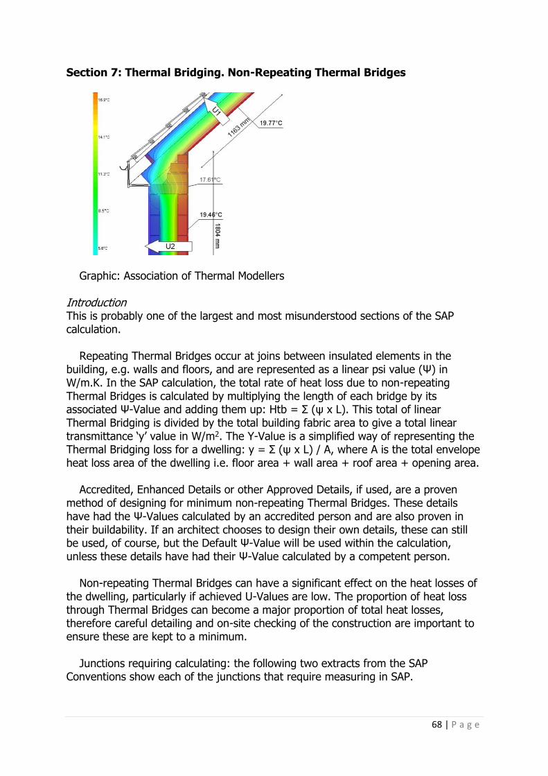
68 | P a g e
Section 7: Thermal Bridging. Non-Repeating Thermal Bridges
Graphic: Association of Thermal Modellers Introduction This is probably one of the largest and most misunderstood sections of the SAP calculation.
Repeating Thermal Bridges occur at joins between insulated elements in the building, e.g. walls and floors, and are represented as a linear psi value (Ψ) in W/m.K. In the SAP calculation, the total rate of heat loss due to non-repeating Thermal Bridges is calculated by multiplying the length of each bridge by its associated Ψ-Value and adding them up: Htb = Σ (ψ x L). This total of linear Thermal Bridging is divided by the total building fabric area to give a total linear transmittance ‘y’ value in W/m2. The Y-Value is a simplified way of representing the Thermal Bridging loss for a dwelling: y = Σ (ψ x L) / A, where A is the total envelope heat loss area of the dwelling i.e. floor area + wall area + roof area + opening area.
Accredited, Enhanced Details or other Approved Details, if used, are a proven
method of designing for minimum non-repeating Thermal Bridges. These details have had the Ψ-Values calculated by an accredited person and are also proven in their buildability. If an architect chooses to design their own details, these can still be used, of course, but the Default Ψ-Value will be used within the calculation, unless these details have had their Ψ-Value calculated by a competent person.
Non-repeating Thermal Bridges can have a significant effect on the heat losses of
the dwelling, particularly if achieved U-Values are low. The proportion of heat loss through Thermal Bridges can become a major proportion of total heat losses, therefore careful detailing and on-site checking of the construction are important to ensure these are kept to a minimum.
Junctions requiring calculating: the following two extracts from the SAP
Conventions show each of the junctions that require measuring in SAP.

69 | P a g e
Graphic Extract: from the SAP Conventions 17 May 2016 (v6.1)

70 | P a g e
Graphic: Extract from the SAP Conventions 17 May 2016 (v6.1)

71 | P a g e
Graphic: Extracts from the SAP Conventions 17 May 2016 (v6.1) Each junction length is measured from the architect’s drawings and entered in the SAP software. In the software I use there is an option to automatically fill the lengths of the windows junctions – Lintels, Sills and Jambs – which the software takes directly from the openings’ dimensions entered previously. However, if different lintel Ψ-Values are used due to differing-length lintels, these must be entered manually.

72 | P a g e
All other junction lengths must be measured and entered. If there are different constructions where the Ψ-Value could differ, for example a masonry wall corner junction, and timber frame dormer wall corner, then separate entries are made.
Once all the lengths of junctions are added, the appropriate Ψ-Value is selected from three available options:
• Default • Approved
• User Defined: Ψ-Values have been calculated by a person with suitable
expertise and experience using the guidance set out in ‘BR 497, Conventions for calculating linear thermal transmittance and temperature factors’, and ‘BRE IP 1/06, Assessing the effects of thermal bridging at junctions and around openings’

73 | P a g e
Table K1 in SAP 2012 Version 9.92 (October 2013) lists the junctions and the corresponding psi values for each, depending on whether Default or Approved is selected.

74 | P a g e
The first thing to notice about Table K1 is that the Approved Ψ-Values are half the value of the Default Values. The Model Dwelling uses the Approved values, and from my experience it’s rare that any new-build dwelling in SAP will achieve the DFEE required to better the TFEE without the use of Approved details or User Defined details for Thermal Bridging.
It is also worth noting which junctions have the greatest impact, by referring to
the psi values in the table. Of particular note are Lintels, Jambs, Ground floor and Gable insulation at ceiling level. These four junctions should, if possible, be looked at first as their effect on the total Y-Value will be the highest.
Approved Details are ACDs (Accredited Construction Details) and are freely
available from the now archived Planning Portal Website: http://webarchive.nationalarchives.gov.uk/20151113141044/http://www.planningportal.gov.uk/buildingregulations/approveddocuments/partl/bcassociateddocuments9/acd
Graphic: ACD example The problem with these details is that they are a rather ‘one size fits all’ and new dwellings are certainly not all the same. So, whilst some of these details can and should be used, there are better details available, all of which will come under the User-Defined entry. There are many schemes now offering Ψ-Values which can be used within the calculation, see Appendix 1.
How does Thermal Bridging affect the SAP result? Using the eight test dwellings, Table 20 below shows how the Default and Approved will vary the DER and DFEE. I’ve not shown any User Defined as this would depend on what construction was used and what details were chosen. Not all User-Defined details are better than the Approved, some are slightly worse. Therefore, it’s always wise to check before using any of them, not only because of the result in SAP, but more importantly that they are the correct junction details for the job.
I should also point out that it’s not all or nothing. The Thermal Bridging screen can have psi values from different sources for different junctions, and for the same type of junctions. The calculation could have Default Values for those where Approved do not exist, like the Roof Ridge, Approved for Ground floor to External Wall, and User Defined for a Lintel, and so on. The number of entries can also be

75 | P a g e
increased for a particular junction, so if it’s a masonry cavity wall, an Approved detail may be used for some junctions, but it could be a different construction for a masonry cavity wall elsewhere in the dwelling, and for this a User Defined is used. It should also be noted that not all junctions have an ACD, although there may be a calculated Ψ-Value in one of the sources listed in Appendix 1, which would be better than using the Default given in Table K1.
One final note: if, once the Thermal Bridging calculation is complete and the total
Y-Value is over 0.15, it is acceptable to default back by accepting the option to use the Default Thermal-Bridging Y-Value of 0.15. This is generally an option that is used when calculating L1B SAP for existing buildings, where Thermal Bridging calculations are not required. For all new-build dwellings, the lengths of junctions and the appropriate Ψ-Values must be calculated and entered, and only then if collectively they amount to a higher Y-Value than 0.15, can this Default option be used. This actually happens quite a lot on flats, especially mid-floor flats, where some of the junctions can be very long.
To keep Table 20, below, from being too unwieldy, I have shown the results for
the dwellings using either all Default Values, or all Approved. Obviously, where a greater or lesser proportion of Approved is used, the results will vary and, of course, if User Defined were used this would change the results further. The Table is, therefore, here as an illustrative guide only as to the effect of better detailing! Table 20: Default and Approved Y-Values and Their Effect on the DER and DFEE
Dwelling Type TER DER with Default
DER with Approved
TFEE DFEE with Default
DFEE with Approved
Detached 18.46 20.49 18.30 62.9 71.9 60.7
Semi detached 14.29 16.22 14.24 49.4 57.8 47.8
End terrace 18.76 20.23 18.45 51.2 58.7 49.8
Detached 15.73 17.54 15.24 55.6 63.3 51.6
Mid terrace 17.6 19.30 17.29 45.2 54.0 44.0
Top Floor 16.66 17.66 15.72 45.1 50.3 40.4
Ground floor 16.31 17.16 15.46 44.6 48.9 40.3
Mid floor 14.67 16.13 14.44 37.3 44.7 36.2
As can be seen, the impact of using Approved Details (or better User Defined) for
Thermal Bridging cannot be over emphasised. With such a difference in the figures between DFEE/TFEE, it would very difficult to make up the shortfall from other input that will affect the result to such a dramatic effect. The DER/TER difference is possible to make up elsewhere, because the DER/TER includes all the SAP input, including the Mechanical and Electrical (M&E), whereas the DFEE/TFEE only uses the input from the thermal efficiency of the dwelling: U-Values, Air Permeability, Thermal Bridging and Ventilation Loss.

76 | P a g e
SAP Evidence Requirements For the final Building Control submission documents and EPC, options include:
• Junction reference numbers and associated signed checklists for any ACDs or ECDs used
• Ψ-Values and checklists by professional bodies • Manufacturers’ Ψ-Values and checklists where they have indicated that the
calculations have been done by persons with suitable expertise and experience • Written confirmation that individual Ψ-Values have been calculated by
someone with suitable expertise and experience The transmission heat transfer coefficient associated with non-repeating Thermal
Bridges must be calculated, or the calculation verified, by the SAP assessor; a Y-Value can only be used if it is:
(a) the Default Value of 0.15, or: (b) derived from Thermal Bridges calculated following the rules in SAP 2012
Appendix K, or: (c) calculated for another dwelling that is identical except for orientation.
At the design stage: For a junction to be assigned a Ψ-Value for an Accredited Construction Detail (ACD) or an Enhanced Construction Detail (ECD) for the purposes of SAP calculations, a list of the intended junction detail reference numbers should be confirmed by the client/designer. The Thermal Bridging should be specified using (a), (b) or (c) above.
At the As-Built stage: For a junction to be assigned a Ψ-Value for an ACD or an ECD for the purposes of SAP calculations, confirmation is needed from the builder that the specific junction has been built in accordance with Accredited Construction Details and that the associated checklists have been completed. A list of the junction detail reference numbers should be confirmed by the client/designer. The values for the design stage are used provided that (a) they were fully specified at the design stage and (b) it is confirmed that no design alterations were made. Summary of Section 7 All Thermal Bridging lengths are measured and multiplied by an appropriate Ψ-Value to generate an overall Y-Value. This figure represents the heat losses in W/m2 due to non-repeating Thermal Bridges.
The Ψ-Value for each junction can either be the SAP Default, an Approved Ψ-Value, or a User-Defined Ψ-Value.
It’s unlikely the dwelling will pass the DFEE/TFEE requirement with the use of
Default Ψ-Values for at least the Lintels, Jambs, Ground-Floor-to-Wall and Gable/Wall (insulated at ceiling) junctions, if not considerably more junctions. Instead, Approved or User Defined are likely to be required.

77 | P a g e
All dwelling designs must consider the heat losses due to non-repeating Thermal Bridges, how to avoid them as much as possible, and understand the effect these can have on the total heat loss of the dwelling, but also how these will be accounted for in the SAP calculation and the effect that they will have on the final results.

78 | P a g e
Section 8: Ventilation This section covers the input for air permeability, Ventilation, both natural and mechanical, and also chimneys, flues and fans.
Air Permeability
Graphic: Air Tightness Testing (UK) Ltd Air permeability for dwellings has a Building Regulations’ maximum level of 10 m3/(h.m2) measured at 50 pascals. This is determined by an air-pressure test conducted on completion of the construction. Each dwelling type will need to be tested, however, on multi dwelling sites. A minimum of three of every dwelling type should be tested. For those untested dwellings, a confidence factor of 2.0 will be added to the test figure when applied to those untested dwellings. This means that air permeability design figures on multiple dwelling sites will need to be set at a maximum of 8 for any dwellings that will not be tested, to be certain that if the actual test figure of 8 is achieved, when the confidence factor is added, the untested dwellings still result in a maximum compliance level of 10.
Input Required for Air Permeability Determine the Design Air Permeability: Yes or No. For Building Regulations compliance an air permeability figure of 10 m3/(h.m2) or less is required.
If seeking an exemption due to < 3 dwellings, this can also be input. A Default of 15 m3/hm2 (@50Pa) will be used in the calculation; although allowed by Building Control, this would, however, be very unlikely to pass the overall DER and DFEE.
Design Air Permeability Rate: this is where the target Design Air Permeability Rate
is input. The Model Dwelling is 5 m3/hm2 (@50Pa) and, for most dwellings, this would be a reasonable figure to achieve.

79 | P a g e
Once the dwelling is completed, there are other fields available to complete, as follows:
Measured Air Permeability Rate: this is taken from the Air test Certificate. This figure will automatically generate an As-Built Air Permeability Rate. They are usually the same figure, except where one dwelling has been tested, and another has not but is identical and, therefore, using the same Air Test Certificate. In this instance the Measured Air Permeability Rate will have 2.0 m3/hm2 (@50Pa) added to the Air Test Certificate figure to produce the As-Built Air Permeability Rate.
An Air Test Certificate reference is input also, this links the SAP calculation with
the Air test Result. Air Tests must be carried out by an ATTMA (Air Tightness Testing & Measurement
Association), a Government-authorised Competent Persons Scheme for the Air Tightness Testing industry, or iATS (Independent Airtightness Testing Scheme). iATS has been developed arising from the withdrawal of The British Institute of Non-Destructive Testing (BINDT) as Scheme Manager of the current competent person scheme for air tightness testing.
Certificates: from ATTMA and iATS Table 21: Test Dwellings – The Effect of Various Air Test Results on the DER
Dwellin
g Type Air
Permeability
15 (Exempt
from test)
Air Permeability
10 (Building
Regs’ maximum)
Air Permeability
5 (Model
Dwelling)
Air Permeability
3
(Requiring MVHR)
TER DER DER DER DER
Detache
d
15.73 17.11 16.73 15.24 14.85
End terrace
18.76 21.29 19.6 18.45 18.15
Mid
terrace
17.60 20.18 18.46 17.29 16.98

80 | P a g e
Table 22: Test Dwellings – The Effect of Various Air Test Results on the DFEE
Dwellin
g Type Air
Permeability
15 (Exempt from test)
Air
Permeability
10 (Building Regs’
maximum)
Air
Permeability 5
(Model Dwelling)
Air
Permeability 3
(Requiring MVHR)
TFEE DFEE DFEE DFEE DFEE
Detache
d
55.6 61.2 59.2 51.6 49.6
End
terrace
51.2 64.1 55.6 49.8 48.3
Mid terrace
45.2 58.5 49.9 44.0 42.5
Mechanical Ventilation
Graphic: Fairair Input Required for Mechanical Ventilation If a mechanical ventilation is not present the Calculation assumes natural ventilation, and no other input is required.
The following forms of mechanical Ventilation are possible to model: • Balanced with heat recovery (MVHR: Mechanical Ventilation with Heat
Recovery) • Balanced without heat recovery (MV: Mechanical Ventilation) • Centralised Whole House Extract • Decentralised Whole House Extract • Positive Input from Loft
• Positive Input from Outside

81 | P a g e
Balanced with heat recovery The system efficiencies can either be chosen by selecting the SAP Default, Design Estimates, or the Product Database. This system is usually required when the air permeability is designed to be 3m3/(h.m2) or below.
It’s preferable that the Make and Model are known, and the appropriate Model is selected from the Product Database. This will ensure the Specific Fan Power (SFP W/l/s) and Heat Exchange Efficiency are correct.
If the Make and Model are not confirmed, design estimates for the above figures
could be input. The Building Regulations’ maximum performance is an SFP of 1.5 W/l/s and a Heat Exchange Efficiency of 70%.
The SAP Default is an SFP 2.0 W/l/s and a Heat Exchange Efficiency of 66%;
using this would flag up a fail for Part L. (SAP 2012 Version 9.92 [October 2013] Table 4g: Default specific fan power for mechanical ventilation systems and heat-recovery efficiency for MVHR systems.)
The Product Database lists products with an SFP as low as 0.51 W/l/s and a Heat
Exchange Efficiency as high as 94%.
Mechanical ventilation systems with heat recovery often do improve the SAP rating, but they may not. This is due to the electricity used in the fans associated with the system, hence the lower the SFP in relation to the volume of the dwelling, the better. Where the cost of the electricity consumed is greater than the cost of the heat saved then the total running costs and CO2 emissions will increase and the energy ratings will decrease.
If the SFP of the fans is below 1 W/(l/s) of extract air, then the total running costs
and CO2 emissions should decrease and the energy ratings increase.
Other Input Required: Is the Installer Approved or not? A lower in-use factor is assumed in the SAP calculation where an approved installation scheme is used. This only applies to balanced systems and centralised whole house systems. The appropriate quantity of wet rooms plus the kitchen. The Duct type, either flexible/mixed, rigid or semi-rigid.
The Duct Source: this can either be the SAP Default, which is usually ok as the alternative, or Ducting from the Product Characteristics Database (PCDB), but this has only eighteen systems currently listed. Lower in-use factors are assumed in the SAP calculation if rigid ductwork is selected or if semi-rigid ducts are listed in the PCDB (see SAP 2012 Version 9.92 [October 2013], Table 4h).
The final input is if the ductwork is insulated or un-insulated – one would hope it was! The in-use factor for heat recovery efficiency is 0.7 where there are un-

82 | P a g e
insulated ducts, and 0.85 where there are insulated ducts. Insulated ductwork is input when all of the ductwork is inside the insulated envelope of the dwelling, even if the ductwork itself is not insulated.
Balanced without heat recovery This is a similar system to the above, but without the heat recovery element. There are none in the Product Database, so really the only option is to enter SAP Default with its SFP 2.0 W/l/s.
The issue with this system, is why would it be specified instead of one which is more efficient with heat recovery? In most dwellings it would seem odd to do so.
For both of the above Balanced type ventilation systems, in the SAP calculation, a
throughput of 0.5 air changes per hour is assumed through the mechanical ventilation system (which is then added to the estimated infiltration rate to calculate the total air-change rate).
Centralised Whole House Extract and Decentralised Whole House Extract
Graphic: Greenwood Airvac
There are systems listed in the PCDB, with SFPs as low as 0.17 W/l/s for Centralised and 0.12 W/l/s for Decentralised.
The SAP Default can also be selected, but the SFP is 0.8 W/l/s.
Other Input Required: if the Installer is Approved or not, and the appropriate quantity of wet rooms plus the kitchen.
Centralised Whole House Extract refers to a fan-driven ventilation system that only exhausts air from the wet rooms in a dwelling via ducting and a central fan. Again, a throughput of 0.5 air changes per hour is assumed in the SAP calculation.
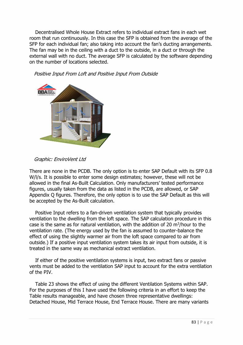
83 | P a g e
Decentralised Whole House Extract refers to individual extract fans in each wet room that run continuously. In this case the SFP is obtained from the average of the SFP for each individual fan; also taking into account the fan’s ducting arrangements. The fan may be in the ceiling with a duct to the outside, in a duct or through the external wall with no duct. The average SFP is calculated by the software depending on the number of locations selected. Positive Input From Loft and Positive Input From Outside
Graphic: EnviroVent Ltd There are none in the PCDB. The only option is to enter SAP Default with its SFP 0.8 W/l/s. It is possible to enter some design estimates; however, these will not be allowed in the final As-Built Calculation. Only manufacturers’ tested performance figures, usually taken from the data as listed in the PCDB, are allowed, or SAP Appendix Q figures. Therefore, the only option is to use the SAP Default as this will be accepted by the As-Built calculation.
Positive Input refers to a fan-driven ventilation system that typically provides ventilation to the dwelling from the loft space. The SAP calculation procedure in this case is the same as for natural ventilation, with the addition of 20 m3/hour to the ventilation rate. (The energy used by the fan is assumed to counter-balance the effect of using the slightly warmer air from the loft space compared to air from outside.) If a positive input ventilation system takes its air input from outside, it is treated in the same way as mechanical extract ventilation.
If either of the positive ventilation systems is input, two extract fans or passive
vents must be added to the ventilation SAP input to account for the extra ventilation of the PIV.
Table 23 shows the effect of using the different Ventilation Systems within SAP. For the purposes of this I have used the following criteria in an effort to keep the Table results manageable, and have chosen three representative dwellings: Detached House, Mid Terrace House, End Terrace House. There are many variants
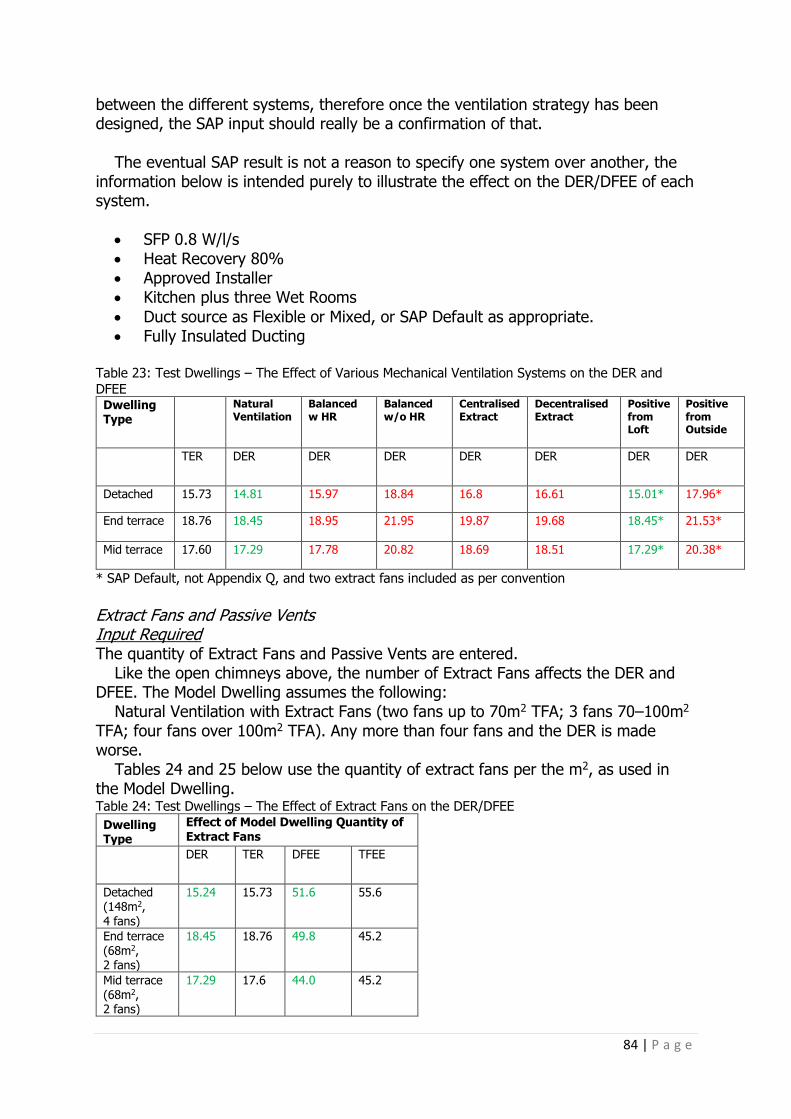
84 | P a g e
between the different systems, therefore once the ventilation strategy has been designed, the SAP input should really be a confirmation of that.
The eventual SAP result is not a reason to specify one system over another, the information below is intended purely to illustrate the effect on the DER/DFEE of each system.
• SFP 0.8 W/l/s • Heat Recovery 80% • Approved Installer • Kitchen plus three Wet Rooms
• Duct source as Flexible or Mixed, or SAP Default as appropriate. • Fully Insulated Ducting
Table 23: Test Dwellings – The Effect of Various Mechanical Ventilation Systems on the DER and
DFEE Dwelling Type
Natural Ventilation
Balanced w HR
Balanced w/o HR
Centralised Extract
Decentralised Extract
Positive from Loft
Positive from Outside
TER DER DER DER DER DER DER DER
Detached 15.73 14.81 15.97 18.84 16.8 16.61 15.01* 17.96*
End terrace 18.76 18.45 18.95 21.95 19.87 19.68 18.45* 21.53*
Mid terrace 17.60 17.29 17.78 20.82 18.69 18.51 17.29* 20.38*
* SAP Default, not Appendix Q, and two extract fans included as per convention
Extract Fans and Passive Vents Input Required The quantity of Extract Fans and Passive Vents are entered.
Like the open chimneys above, the number of Extract Fans affects the DER and DFEE. The Model Dwelling assumes the following:
Natural Ventilation with Extract Fans (two fans up to 70m2 TFA; 3 fans 70–100m2 TFA; four fans over 100m2 TFA). Any more than four fans and the DER is made worse.
Tables 24 and 25 below use the quantity of extract fans per the m2, as used in the Model Dwelling. Table 24: Test Dwellings – The Effect of Extract Fans on the DER/DFEE
Dwelling Type
Effect of Model Dwelling Quantity of Extract Fans
DER TER DFEE TFEE
Detached (148m2, 4 fans)
15.24 15.73 51.6 55.6
End terrace (68m2, 2 fans)
18.45 18.76 49.8 45.2
Mid terrace (68m2, 2 fans)
17.29 17.6 44.0 45.2

85 | P a g e
Table 25: Test Dwellings – The Effect of Passive Vents on the DER/DFEE
Dwelling Type
Effect of Model Dwelling Quantity of Passive Vents
DER TER DFEE TFEE
Detached (148m2, 4 fans)
14.81 15.73 51.6 55.6
End terrace (68m2, 2 fans)
18.93 18.76 49.8 51.2
Mid terrace
(68m2, 2 fans)
17.78 17.6 44.0 45.2
Chimneys and Flues Input Required The quantity of Chimneys and Flues are entered. Any vertical opening with an area greater than a duct of 200mm diameter counts as a chimney, any less and it’s a flue. Flueless gas fires are assumed to lead to the same air-change rate as an open chimney (40 m3/hour). Table 26: Test Dwellings – How Open Fires Affect DER and the DFEE
Dwelling Type
Effect of 1 x Open Fireplace If No Open
Fireplace
TER DER TFEE DFEE DER DFEE
Detached 15.73 15.81 55.6 54.5 15.24 51.6
End
terrace
18.76 19.54 45.2 55.2 18.45 49.8
Mid
terrace
17.6 19.3 45.2 53.3 17.29 44.0
Table 27: Test Dwellings – How Open Flues Affect DER and the DFEE
Dwelling
Type
Effect of 1 x Open Flue If No Open Flue
TER DER TFEE DFEE DER DFEE
Detached 15.73 16.15 55.6 56.2 15.24 51.6
End
terrace 18.76 18.93 45.2 52.2 18.45 49.8
Mid
terrace 17.6 17.78 45.2 46.5 17.29 44.0

86 | P a g e
Table 28: Test Dwellings – How Flueless Gas Fires affect DER and the DFEE
Dwelling
Type
Effect of 1 x Flueless Gas Fire If No Flueless
Gas Fire
TER DER TFEE DFEE DER DFEE
Detached 15.7 16.15 55.6 56.2 15.24 51.6
End terrace
18.7 19.54 45.2 55.2 18.45 49.8
Mid
terrace 17.6 18.39 45.2 45.2 17.29 44.00
SAP Evidence Requirements: Air Permeability Air Permeability – Pressure test – For the final Building Control submission documents and EPC.
The As-Built assessment cannot be processed unless: (a) pressure test data is provided: the test results, or a certificate from a person
registered by an authorised air pressure testing scheme, for that dwelling. For a dwelling that was not tested: • The test results, or a certificate from a person registered by an authorised air
pressure testing scheme, for dwellings of the same dwelling type that were used to derive the input value on each development site; or
• If the dwelling is on a development site with no more than two dwellings: – test results, or a certificate from a person registered by an authorised air
pressure testing scheme, of a dwelling of the same dwelling type constructed by the same builder during the preceding twelve-month period, or;
– Where the test results or a certificate cannot be provided, the value of 15m3/(h.m2) at 50Pa may be used in the SAP calculation.
(b) In England the special conditions of AD L1A 2013 paragraph 3.22, or AD L1A
2010 paragraph 5.23 apply, or: (c) Evidence of a specific dispensation issued in writing by Building Control.
Mechanical Ventilation Systems: SAP Evidence Requirements For the final Building Control submission documents and EPC: Commissioning Certificates for Mechanical ventilations and Extract systems, including installed SFP W/l/s, and, where applicable, the Heat Recovery percentage.
Confirmation of the number of Extract fans if electric or passive extract fans.
Summary of Section 8 This section of SAP is very much a reflection of the design criteria for the dwelling. In as much as SAP should not be used as a Design Tool, but so often is, this section is one of those where it most definitely should not. The ventilation strategy has a completely separate design criteria and the SAP calculation should reflect that designed strategy. Having said this, it’s worth knowing what will adversely affect the

87 | P a g e
DER/DFEE, in so much as if the dwelling needs a certain type of ventilation/extract, other measures may need to be improved to counteract the effect of this strategy.
Natural Ventilation with local extracts is usually the best resulting strategy, depending on the number of extracts required in comparison to the Model Dwelling.
Mechanical Ventilation, with heat recovery, can also benefit the DER/DFEE as long
as the SFP of the fans is below 1.0 W/(l/s) of extract air, then the total running costs and CO2 emissions should decrease and the energy ratings increase.
Other forms of Mechanical Ventilation usually do give a poorer result (see Table 23, above) but this does not mean they should not be used, if the design requires
it. Open Flues, Chimneys etc are not part of the ventilation system in terms of
providing the required fresh air. Instead, they are to take gasses away, so although essential if an appliance requires it, they are ‘holes’ in the building fabric that will also let heat out, therefore these will be penalised in the DER/DFEE results, and this will need to be accounted for elsewhere in the design.
Air tightness: The Model Dwelling has an air tightness of 5.0 m3/hm2 (@50Pa), so
although the Building Regulations states a maximum of 10 m3/hm2 (@50Pa), the dwelling is unlikely to pass at that level. If MVHR is installed, air tightness should really be set at a maximum of 3.0 m3/hm2 (@50Pa).
All air-tightness targets must be confirmed with an air test upon the dwelling’s
completion.

88 | P a g e
Section 9: Space Heating This looks in detail at the heating input required for SAP. Obviously, the range of heating types is wide so whilst trying to show the effect of each type in a calculation, there are too many variants to show them all.
The energy required from the heating system is calculated from the specific heat loss, the degree-days and the solar and internal gains to determine the space heating requirements. The SAP calculations assume that the heating system(s) is(are) capable of heating the entire dwelling.
First, let’s look at the input required into the SAP software.
Input Required Either one or two Individual Heating Systems, or one main Community Heating System and a number of back-up systems can be input. When there are two main systems, system one always heats the living area. If a system is capable of heating at least 30% of the dwelling, this is the main heating system.
If the main heating is two systems, this is divided between them based upon the floor area that they serve. If there are two boilers serving the same distribution system, or where there are two solid-fuel systems, the fraction of heat from both is taken as 0.5.
One Secondary Heating System may be input, for example a wood burner. This is
one that would supplement the main heating, or is for rooms not heated by the main system. If there is an open chimney and hearth capable of supporting an open fire, this must also be included. And if Storage Heaters or off-peak electric under-floor heating are the main heating system, secondary heating must be input as direct-acting, electric room heaters.
SAP 2012 Version 9.92 (October 2013), Table 11: fraction of heat supplied by secondary heating systems. All secondary heating is 10%, except when the main is electric room heaters (20%), and non-fan-assisted electric storage heaters (15%). When heat pumps are the main heating source, the fraction will vary; see SAP 2012 Version 9.92 (October 2013), Appendix N3.7.
If secondary heating is not present, a secondary heating system is still used for
the calculation of the energy use and energy ratings where the main system is not sufficient to heat all habitable rooms in the dwelling to the level on which the SAP is based (21°C in the living area and 18°C elsewhere). This is applicable if there are any habitable rooms without heat emitters associated with the main heating system.
If no secondary heating is present but there is an open chimney, it will have an adverse effect on the DER. If there is an unconnected gas point in the location this should also be input although it makes no difference to any results.

89 | P a g e
Table 29: Test Dwelling – Comparing the DER with Secondary Heating, Specified and Not Specified, Where There is an Open Flue or Chimney
Detached Dwelling With Secondary Heating Without Secondary Heating
and Open Flue or Chimney
TER DER DER
15.73 15.24 16.18
If no main heating is specified – unusual, but it can happen (Passivhaus can be
designed without a main heating system) – then direct-acting electric heaters are input even though they are not actually present. This would make it very difficult to achieve an overall pass with the DER if the dwelling was anything other than a higher-performing Passivhaus designed dwelling. The poor performance by the electric heaters as main heating would be offset by the very low U-Values and, in particular, the very low air permeability of a Passivhaus, which would be unlikely to be achieved in a dwelling which had not been designed to Passivhaus standard.
Boiler as a main heating system Efficiency Source: this can either be the SAP Default, Manufacturer Declared, from the Micro Combined Heat & Power (CHP) Database, if applicable, or most likely – and most preferable – from the PCDB.
The PCDB lists over six thousand products and is updated at the beginning of each month. The SAP software should be updated accordingly each month. When I am asked to complete the As-Built assessment, I need to know the exact boiler make and model number, and am often given, ‘It’s a Worcester Greenstar 27.’ Below is a screenshot of the PCDB showing the number of Worcester Greenstar 27s! Note the differences in efficiencies.

90 | P a g e
Screenshot PCDB
Graphic: Screenshot from NHER Plan Assessor Further information can be found from http://www.ncm-pcdb.org.uk/sap/searchpod.jsp?id=17 if required. For the purposes of this book, I will assume the chosen method of heating is listed in the PCDB, as one of its main purposes is to show the difference the various inputs have on the final results.
If a SAP Default is used, it’s invariably going to be of a lower efficiency than an actual product in the Database. Full details are in SAP 2012 Version 9.92 (October 2013), Table 4b: Seasonal Efficiency for gas and oil boilers. The Winter Seasonal Efficiency is the figure used for space heating.
By selecting a boiler from the Database, the boiler type, fuel (if condensing or
not), the flue type, and if fan-assisted are all fields that are automatically completed. If any of the other options are selected for a boiler, all of the above need to be manually input.

91 | P a g e
Table 30: Test Dwelling – The Effect of Boilers Selected From Either SAP Default or the Product Database on DER
SAP Table 4b:
Seasonal Efficiency
Building Regulations’
Minimum Efficiency
Specified Boiler
From Product Database*
Boiler Efficiency 84% 88% 89.5%
TER 15.73 15.73 15.73
DER 16.60 15.79 15.56
*Glow-worm Ultracom 2 12sxi
All boilers in the Table above have the following criteria: Regular gas boiler, Balanced fan-assisted flue, Condensing with Auto Ignition (1998 or later).
Heating Controls
Boiler Controls need to be selected from the following options, although in reality ‘Time and Temperature Zone Control’ (T&TZC) is the only one that gives a good result on the DER. This is because the Model Dwelling also has this. There are two options for selecting this: T&TZC Plumbing Circuit, and T&TZC Database. The only issue with this is that there is nothing in the Database as yet, therefore the only option is to select plumbing circuit. As it’s the only option, it makes no difference that can be seen in the DER, but once products do start to appear, this probably won’t always be so. Time and Temperature Zone Control For a system to be specified with time and temperature zone control it must be possible to programme the heating times of at least two zones independently, as well as having independent temperature controls. In the case of boiler-based systems, this requires separate plumbing circuits and at least two programmers or separate time channels in the programmer. In the case of electric heating systems, time and temperature zone control can be achieved by providing separate time and temperature controls for different rooms.

92 | P a g e
Time and Temperature Zone Control is applicable when the following conditions are met:
• There are at least two zones in which heating times and temperatures are
controlled independently of each other • Each zone i.e. either a single room or a number of joined rooms and the zone
are separated by internal doors • One of the zones includes the living room • If the controls are programmable/communicating TRVs, they are fitted to all
radiators in the zone • Zones with time and temperature control, taken together, cover at least 80%
of the floor area • Timing does not depend on a shared time switch or programmer controlling
all zones simultaneously • Where there is no demand for heating in a zone, boiler interlock is assured • If domestic hot water is controlled by the same device as that for Time and
Temperature Zone control, it must have its own time and temperature control for the hot water
Other controls options: • No Time or Temperature Control • Programmer, no room thermostat • Room thermostat only
• Programmer and room thermostat • Programmer and at least two room thermostats • Programmer, room thermostat and TRVs • TRVs and Bypass • Programmer, TRVs and Bypass
• Programmer, TRVs and flow switch • Programmer, TRVs and energy manager
Table 31: Test Dwelling – The Effect of Different Boiler Control Options on the DER
Boiler Control Type TER DER
Time and Temp Zone Control – Plumbing Circuit
15.73 15.24
Programmer, TRVs and energy manager
15.73 16.49
Programmer, TRVs and flow
switch
15.73 16.49
Programmer, TRVs and Bypass 15.73 16.52
TRVs and Bypass 15.73 16.52
Programmer, room thermostat
and TRVs
15.73 16.49
Programmer and at least two
room thermostat
15.73 16.49
Programmer and room thermostat
15.73 17.00
Room thermostat only 15.73 17.00
Programmer, no room thermostat
15.73 17.92
No Time or Temperature Control 15.73 17.92

93 | P a g e
Other issues under the Controls are also taken into the calculation: Boiler Interlock: without this present the boiler fails the minimum requirements of
Part L1A of the Building Regulations in England, and in reality, it’s unlikely it wouldn’t be there in the heating design.
Delayed Start Thermostat: if the room temperature has not dropped as much as
usual during the heating off period, the delayed-start thermostat delays the heating switch from coming on at the start of a heating period. It has a limited effect on the DER, if present.
Table 32: Test Dwelling – The Effect on the DER of the Presence of a Delayed-Start Thermostat
Boiler Control Type TER DER
Delayed-Start Thermostat Present
15.73 15.03
Delayed-Start Thermostat Not
Present
15.73 15.24
Weather or Load Compensation: compensators can be applied only if located in
the database. This is only applicable to condensing boilers or heat pumps supplying a wet heating system. When either an enhanced load compensator or weather compensator is fitted to a condensing boiler it enables the boiler to operate more efficiently.
The specific load or weather compensator has to be selected from the Product
Database, and the efficiency adjustment applied is determined by the data in the Database.
A weather compensator adjusts the temperature of the water circulating through
the heating system according to the temperature measured outside the dwelling. An enhanced load compensator maintains the temperature inside the dwelling by
sensing and limiting the temperature of the water circulating through the boiler and heat emitters in relation to the temperature measured inside the building.
Not all boilers are compatible with the above. If the selected boiler is not
compatible, it’s not possible to select a compensator from the PCDB. Therefore, if required, it’s best to know if the chosen boiler has this as an option. It’s possible to ascertain this from the PCDB using the binary code displayed when a boiler is selected. Each control or weather-compensator product family (set of similar controls from a manufacturer) in the PCDB has a position in the Control type binary number assigned to it. Each boiler then has either a 1 if compatible, or a 0 if not compatible in each of those positions. An assessor has access to this, so checking which compatible controls the proposed boiler has is relatively easy.
The Model Dwelling does have weather compensation included, so, if possible, it’s
worth considering. The effect of the compensator on the DER is noticeable.
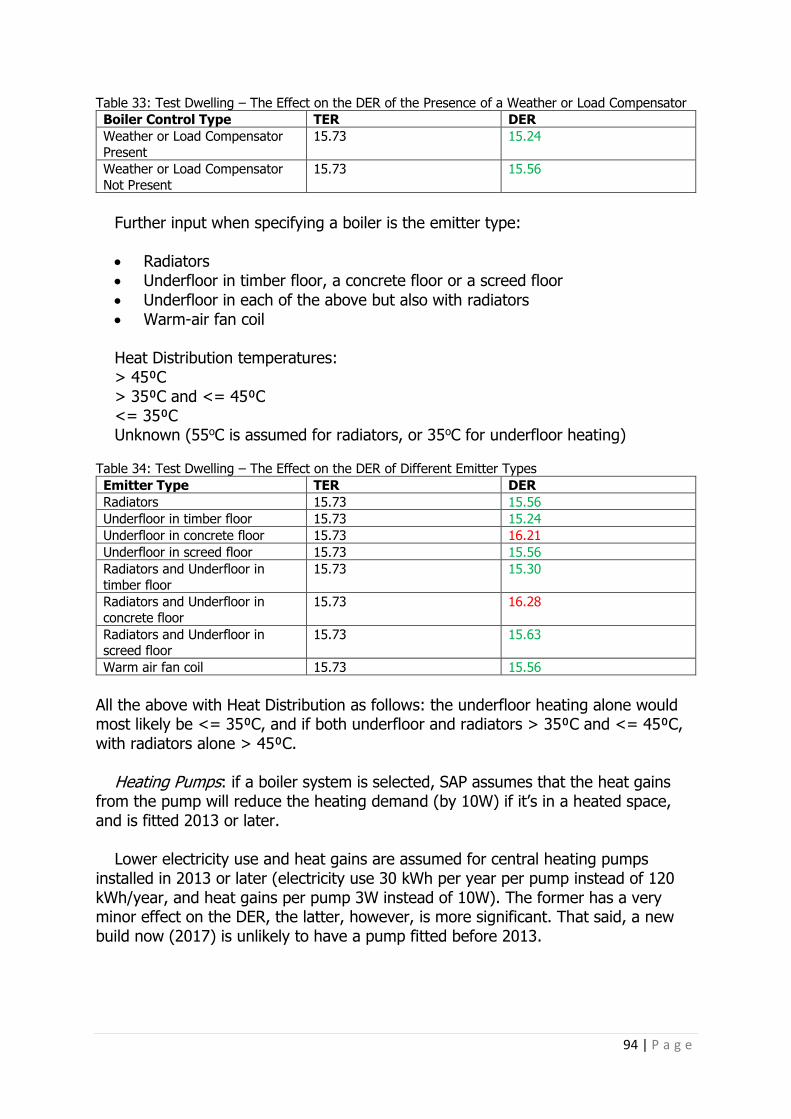
94 | P a g e
Table 33: Test Dwelling – The Effect on the DER of the Presence of a Weather or Load Compensator
Boiler Control Type TER DER
Weather or Load Compensator
Present
15.73 15.24
Weather or Load Compensator
Not Present
15.73 15.56
Further input when specifying a boiler is the emitter type: • Radiators • Underfloor in timber floor, a concrete floor or a screed floor
• Underfloor in each of the above but also with radiators • Warm-air fan coil Heat Distribution temperatures: > 45⁰C > 35⁰C and <= 45⁰C <= 35⁰C Unknown (55oC is assumed for radiators, or 35oC for underfloor heating)
Table 34: Test Dwelling – The Effect on the DER of Different Emitter Types
Emitter Type TER DER
Radiators 15.73 15.56
Underfloor in timber floor 15.73 15.24
Underfloor in concrete floor 15.73 16.21
Underfloor in screed floor 15.73 15.56
Radiators and Underfloor in
timber floor
15.73 15.30
Radiators and Underfloor in
concrete floor
15.73 16.28
Radiators and Underfloor in screed floor
15.73 15.63
Warm air fan coil 15.73 15.56
All the above with Heat Distribution as follows: the underfloor heating alone would most likely be <= 35⁰C, and if both underfloor and radiators > 35⁰C and <= 45⁰C, with radiators alone > 45⁰C.
Heating Pumps: if a boiler system is selected, SAP assumes that the heat gains from the pump will reduce the heating demand (by 10W) if it’s in a heated space, and is fitted 2013 or later.
Lower electricity use and heat gains are assumed for central heating pumps
installed in 2013 or later (electricity use 30 kWh per year per pump instead of 120 kWh/year, and heat gains per pump 3W instead of 10W). The former has a very minor effect on the DER, the latter, however, is more significant. That said, a new build now (2017) is unlikely to have a pump fitted before 2013.

95 | P a g e
Flue Gas Heat Recovery Systems (FGHRS)
Graphic: SuperHomes
If a FGHRS is present, this can also be modelled in SAP and the advantages of installing one can be a reduction in the DER. All available FGHRS are listed in the PCDB. Therefore, if it’s not listed, it can’t be used in the calculation; there is no SAP Default version. Currently, there are only twenty-two available but they are not linked to particular boilers, unlike the weather compensators, so it is possible to specify a FGHRS on a boiler that cannot accommodate it. It is, therefore, vital that a check is made to ensure the system is compatible, otherwise the benefit of the FGHRS will be lost when the final As-Built checks are made. Table 35: Test Dwelling – The Effect of a FGHRS on a Boiler System
Dwelling Type Boiler Model FGHRS Model TER DER
Detached
House
Glow Worm
Ultracom 2
n/a 15.73 15.24
Detached
House
Glow Worm
Ultracom 2
Glow Worm
PFGHRD/1 60/100
15.73 15.17
Mid Terrace House
Glow Worm Ultracom 2
n/a 17.6 17.29
Mid Terrace
House
Glow Worm
Ultracom 2
Glow Worm
PFGHRD/1 60/100
17.6 16.98
Detached
House
Baxi Eco Blue 12
System ERP
n/a 15.73 15.61
Detached House
Baxi Eco Blue 12 System ERP
Zenex GS-1 15.73 15.19
Mid Terrace
House
Baxi Eco Blue 12
System ERP
n/a 17.6 17.58
Mid Terrace
House
Baxi Eco Blue 12
System ERP
Zenex GS-1 17.6 17.07
The claims made by some manufacturers are perhaps more than they deliver.
However, the different FGHRS combined with the different boiler models will give varying results, so although the example above looks as if not having one makes very little difference, the choice of system will be important. If a FGHRS is present,

96 | P a g e
the efficiency increase assigned to underfloor heating and load/weather compensation is not applied (to avoid double counting).
Significance of Fuel Type The SAP calculation uses Fuel emissions factors within the calculation methodology: each fuel type has its own CO2 emissions factor, detailed in full in ‘SAP 2012 Version 9.92 (October 2013), Table 12: Fuel prices, emission factors and primary energy factors’.
Table 36: Fuel Emissions Factors Used in SAP
Fuel Emissions kg CO2 per kWh
Wood Logs 0.019 Main Gas 0.216 LPG 0.241 Oil 0.298 Electricity 0.519
I won’t dwell on the figures themselves, the main point is the difference between
them as this is directly represented in the eventual DER results. If a heating source uses electricity, it’s going to have a much higher CO2 emission associated with it than mains gas, and, therefore, is going to be more difficult to achieve a pass overall. Likewise, in secondary heating, if a closed wood burner is input, compared to a mains gas fire, the wood burner is going to produce a much lower DER than the gas fire. Often the choice of fuel is a given – in towns where mains gas is available, it is usually used, unless electric is the preferred option. In rural areas where no mains gas is available, the only options are to go with LPG, oil, electricity or perhaps some form of biomass/biogas.
If we take one of the test houses and replace the gas boiler with a boiler that
uses either LPG or Oil, the results are as follows: Table 37: Test Dwelling – The Effect of Boiler Fuel Type on the DER
Boiler
Efficiency
Fuel TER DER
89.5% Mains Gas 15.73 15.56
89.7% LPG 15.73 16.69
89.5% Oil 15.73 19.48
The above doesn’t use the exact same boiler in each case. However, the point is
to see the effect that fuel plays on the DER, and, as can be seen, there is a significant difference between them. If mains gas cannot be used, then this difference in the DER, by using the other fuels, will have to be accounted for elsewhere in the design.

97 | P a g e
Electric Heating
You may have already determined that heating by electric, due to the high CO2
emissions factors, as detailed above, is going to be much harder to gain a pass overall than a gas system.
The choice of Electric systems are as follows: • Storage Heaters • Warm Air • Heat Pump: wet system or warm air • Room Heaters • Electric Ceiling Heating
• Electric Underfloor Heating
Electric Heating Required Input Storage heaters: either the SAP Default or PCDB can be used to select the models.
Warm air: either the SAP Default or Product Database can be used to select the models.
Room Heaters: either the SAP Default or Manufacturer-Declared values are used. System choice is between Panel, Convector or Radiant Heaters, Fan Heaters,
Portable Electric Heaters or Water-/Oil-filled Radiators. There are various controls options, Programmer and Room Thermostat giving the
lowest DER. As long as the efficiency and the controls are the same, it doesn’t make any
difference which emitter is selected in the DER result. Electric Ceiling Heating: there is just direct input for this heating type, with a
choice of controls only, the rest of the input being assumed by the SAP software. Electric Underfloor Heating: again, this is just direct input, as above, except that
the floor type is selected, in Timber Floor, Screed Floor, Concrete Floor or integrated with direct-acting heaters, either on standard-rate electricity or with a low rate.

98 | P a g e
Control selection is the same as for other electric heating. Like the boiler to underfloor heating, the worst performing is the concrete floor,
the best a timber floor. Integrated with direct-acting heaters is better with duel-rate electricity than the
single rate.
Table 38: Test Dwelling – The Effect of Boiler and Electric Heating Options on the DER, in the Same Dwelling
Heat Source DHW TER DER
Gas Boiler From gas boiler 15.73 15.24 Storage Heater Dual immersion 23.28 30.64 Warm Air Heating Dual immersion 15.75 19.17 Panel Heater Dual immersion 23.28 28.75 Electric Ceiling Heating Dual immersion 23.28 30.79 Electric Underfloor
Heating Dual immersion 23.28 30.04
Table 38 notes: in a test dwelling, for electric heating, the electricity tariff has
been changed to Off-Peak 7 hour, and the hot water to a dual-core electric immersion.
Warm air: the model chosen for the above Table has an efficiency of 88% and
time and temperature zone controls. Panel Heater: in the above Table an efficiency of 95%. Electric under-floor heating in a timber floor, with time and temp zone controls.
It would seem, when assessing the above electric options for heating and comparing to the same dwelling, that doing so would not be possible because they all fail. This is true to a point, but it also highlights that the SAP calculation input cannot be taken in isolation. Electric heating may be necessary in some dwellings, and if so this is fine, as long as other measures are taken to improve performance elsewhere to account for the effect electric heating has on the DER. The obvious solution, of course, would be to introduce a renewable like Photovoltaic (PV), as this will obviously work very well when combined with an all-electric system, at least for part of the year anyway.
Heat Pumps

99 | P a g e
Heat Pump: Wet Systems includes both ASHP and GSHP in the PCDB If a heat pump is the chosen heating system, the selection criteria is very similar to that of a boiler. Either the SAP Default or from the PCDB. Like a boiler, selecting from the PCDB is preferable and will automatically populate a number of input fields based upon the selected model.
‘SAP 2012 Version 9.92 (October 2013), Table 4a: Heating Systems (space and water) Category 5: HEAT PUMPS WITH WARM AIR DISTRIBUTION’ lists the efficiencies used in the SAP Default, the efficiency for ASHP at a seasonal efficiency of 170%, and GSHP/WSHP at 230%, considerably lower than might be expected from manufacturers’ data.
If installed by an MCS-accredited installer, this should be input. The Control selection is the same as those for a boiler. Weather compensation will
be automatically included if part of the chosen system. The type of emitter is, likewise, the same as for boilers. For many heat pumps, the hot water storage cylinder will also be automatically
populated. However, this can be overwritten should the chosen cylinder be a different capacity or heat loss.
Assuming all the above is directly taken from the chosen heat pump – in this
example, a Daikin Altherma to underfloor heating with a heat distribution of 35⁰C – the result is TER 23.24/DER14.86. for the same dwelling used in the examples above for electric heating. Note a very healthy pass. Heat Pump: Warm Air There are only two models in the Product Database, and rarely is this type of system specified, therefore I won’t spend much time on it here. Suffice to say the input is similar to that of an ASHP. In addition, the ventilation screen will need amending and the system invariably will provide mechanical ventilation, too. If the system is one of the two Nilan, with Nilan MVHR, the result is a TER 23.29/DER 10.19; again, a very good pass.
If the SAP Default is selected for a wet system heat pump, there is a choice to select either GSHP, ASHP or Water Source Heat Pump, all with either heat distribution of <= 35⁰C, or over.
Even when the basic information assumed for an ASHP to underfloor heating in
screed, where the model and heat distribution temperature is unknown, and there is time and temperature zone control but no weather comp, and hot water is from the SAP Default, the result is a TER is 23.29/DER 19.49. Still a pass.

100 | P a g e
Heat-Loss Parameter (HLP) Well-insulated dwellings may not require heating in all rooms to achieve adequate comfort temperatures. In general, a Heat-Loss Parameter (HLP) of less than 2 means that internal heat transfers between the rooms will ensure that a few rooms can be left unheated.
The HLP is a reflection of the overall level of insulation since most of the areas of heat-loss elements increase with floor area – it can be regarded as an overall average house U-Value. It also takes into account thermal-bridging losses and ventilation losses and is calculated by adding these losses up and dividing by the floor area. A very well designed low-energy house with a high level of all-round insulation would have an HLP of approximately 1.0.
If the HLP is very different from the value expected then the problem is going to
be with one of the losses as identified above, and easily checked by reviewing the input. Community Heating This is only really being specified for larger schemes in the true sense of community heating, although it is also used where one heat source is being used to heat smaller developments too, of maybe only three or four dwellings.
Input Required Heat Sources If the community heating system happens to be in Lerwick, then the Product Database can be used as this contains just the one system, otherwise all the input is entered manually, as follows:
Efficiency is either the SAP Default or Manufacturer details. If the SAP Default is used, the efficiency is as per the SAP Table 4a.
The Type of Heating: Boiler, CHP, Heat Pump, Waste Heat from Power Station or
Geothermal Heat Source. Fuel Type: the Fraction of heat from the main heat source, the Efficiency of the
main heat source and the Heat-to-Power Ratio if it’s a CHP as the main heat source. The same is then repeated for any other heat sources forming part of the system.
It’s unlikely the community heating will be just the one heat source as this will need servicing etc and when it is, a backup is required. Therefore, there is usually always a back system to the main one.
Community System If the Distribution Loss Factor is known, it should be entered.
The Heat Distribution System for all new builds will be either unknown, or preferably either low, medium or high temp full flow, pre insulated.
Controls are options from Flat Rate Charging or Charging Linked to Use.

101 | P a g e
The type of Emitter is the same as for individual heating systems. The results from community heating are very varied, depending on the options
chosen to match the design criteria. As an example, taking one of the test dwellings (a detached house), the following is derived from input provided by a CHP provider:
Main heat source: Gas CHP, 72.7% efficiency, Heat-to-Power Ratio 2.38. Backup Heat Source: Gas Boiler, 89% efficiency. 50/50 split between the two systems. Distribution loss factor of 1.05. Controls are a programmer and at least two thermostats, charging linked to use. Emitter underfloor heating in screed.
Community Heating and DHW When inputting a community system, this also affects the DHW input, which is given here in full rather than in the next section.
For this example, the DHW is from the main heat source, a central cylinder and a plate heat exchanger in the dwelling with a loss factor of 0.5 kWh/24hr and a volume of 10 ltrs.
The DER/TER in the dwelling with an individual gas boiler and cylinder is
TER15.73/DER15.24. The same dwelling, changing to the community heating and DHW, as detailed
above, is TER 15.50/TER 15.35. Both still pass and although the figures have changed, the pass rate is very
similar. The factors that will affect by how much the dwellings pass when community heating is designed, is by the fraction split between the two (or more) systems, their efficiency, and the fuel they use. Sap Evidence Requirements SAP evidence requirements for the final Building Control submission documents and EPC.
Items from the PCDB: heating and hot water systems, heating controllers, mechanical ventilation, FGHRS, WWHRS.
Written confirmation from the developer that the specific products have been
used in the dwelling concerned (sufficient to retrieve from the database). Manufacturer’s declared efficiency values for room heaters: manufacturer’s
declared value as specified in E2 in Appendix E of SAP 2012. Community heating: if not from community network’s database then: • Evidence for plant configuration and efficiency values; • Evidence for choice of distribution loss factor

102 | P a g e
Heating Controls and any compensators must also be confirmed – in particular, time and temperature zone control. This should be manufacturer’s data/information providing such information as to prove they meet the criteria for each control.
Summary of Section 9 It’s important to include a known make and model number of heat source so that it can be selected from the PCDB and all its attributes included within the design calculation. Using SAP Default for a boiler will lead to a poorer result and, if a suggested boiler is used in the calculation, this invariably leads to problems at the As-Built stage if a different model is selected. The SAP Default can, however, usually be ok when a heat pump is specified if the actual model is unknown at design stage.
Know the heat distribution temperature the system will be designed to and the type of emitters to be used.
Apart from Biomass/Biogas, mains gas is still the preferred heating fuel in terms
of lower CO2 emissions. The exception is heating from electric Heat Pumps where their efficiency is such that, although it uses electricity, the level of heat output for each kW of electricity used to produce it can be at least two to three times more, if not higher.
Other forms of electric heating are very CO2-emissions heavy, which will need to
be accounted for elsewhere in the design to make up the shortfall that will invariably be in the DER when using such systems.
Heating Controls and Compensators are important, not only to ensure the system
meets the requirements of Part L1A, but also to achieve the DER. The Model Dwelling will use the best of the Heating Controls, Time and Temperature Zone Control, and also Weather Compensation. There are a number of ways to achieve Time and Temperature Zone Control, and, to use weather compensation, it must be compatible with the chosen heating system.
Flue Gas Heat Recovery can be a way of boosting the results in SAP, although the
better reason to install one may be overall running cost reduction. Secondary heating can have a considerable impact on the DER and, as such, is
important to consider. The best result will come when a closed wood burner is selected, whereas any open fire or electric secondary heat source will be penalised due to either the CO2 emissions or by virtue of there being an open chimney in the dwelling.

103 | P a g e
Section 10: Domestic Hot Water (DHW)
Graphic: Plumb Centre Input Required Type of system: this will be either DHW from the main system, or another source, as follows:
• Immersion • Instant Electric
• Single or Multi-Point gas water heater • Hot-Water-Only boiler, range cooker, heat pump or community scheme Fuel Type: depending on the system type selected, the available fuels for that
type can also be selected. You can’t, for example, select gas if the type is an immersion.
Is the Water separately timed? Usually this is always Yes as this is a Part L1A
requirement. It will also adversely affect the DER if it’s not. Being separately timed is assumed to reduce the storage losses from the hot water system and thus improve the energy rating. To qualify as water separately timed, it must be possible to programme the water for two or more time periods a day, and the space heating to be programmed for at least two different periods per day. This requires a time switch or programmer with more than one time-control channel.
If a Thermal Store or Combined Primary Storage Unit (CPSU) is specified: In the SAP it is required to know if the CPSU is integrated with the main heat
source, or for hot water only, and, if so, is it in an airing cupboard and in a single unit.

104 | P a g e
Storage Details For Hot Water, Cylinder-Based systems the storage losses and the controls will affect the overall performance of the water heating system and the internal gains generated by the system.
There is a choice of selecting Heat Losses (kWh/day), either SAP Default or from the manufacturer.
If from a manufacturer, the only other information required is if the hot water
store is in a heated space or not. If the SAP Default is used then the volume, insulation type and thickness is
entered, plus whether there is a thermostat present, and if the primary pipe work is insulated of not. Pipes must be insulated at least 1m from the cylinder. A thermostat is required to comply with Part L1A, so one is usually assumed to be present in calculation. If the cylinder is not in a heated space there is a minor negative effect on the DER.
‘SAP 2012 Version 9.92 (October 2013), Table 2: Hot water storage loss factor’
provides further details of how the losses are calculated if the SAP Default is used. Let’s take the Test Dwelling – a detached house where the DHW is from the main
heating source, in this case a gas boiler, and is also separately timed. In this example the cylinder losses are known: 1.5 kWh/day with a 250 capacity, it has fully insulated pipework, and is in a heated space with a thermostat present. In other words, a fairly typical design.
If various changes are made to that cylinder, the results of each can be seen
below in Table 38. These are the most significant of the input that will affect the DER.
Table 39: Test Dwelling – The Effect on the DER of Changes in DHW Cylinder Specification
DHW Type Cylinder Heat
Loss
Cylinder
Capacity
Pipework
Insulation
TER DER
From gas
boiler
Manufacturer 1.5
kWh/day
250 ltrs Fully Insulated 15.83 15.54
From gas boiler
Manufacturer 1.8 kWh/day
250 ltrs Fully Insulated 15.83 15.60
From gas
boiler
SAP Default* 250 ltrs Fully Insulated 15.83 15.71
From gas
boiler
SAP Default* 300 ltrs Fully Insulated 15.83 15.78
From gas boiler
Manufacturer 1.5 kWh/day
250 ltrs 1m from cylinder
15.83 15.79
Immersion Manufacturer 1.5
kWh/day
250 ltrs n/a 15.83 18.79
Instant Electric
n/a n/a n/a 15.73 17.12
Single point gas water
heater
n/a n/a n/a 15.73 15.15

105 | P a g e
* Assumes Spray foam insulation at 80mm thickness. If this were 50mm, the DER drops to 15.88, a fail overall.
As can be seen from the above, obviously the more detailed information is given about the cylinder, in particular the storage losses, as well as how well the pipework is insulated, the better the resulting DER. If the losses are known, the volume is irrelevant to the calculation, it’s only when the losses are not known, using the SAP Default, that this becomes important.
The two instantaneous methods of DHW, either by electric or gas, are shown to
indicate how the effect of fuel choice affects the DER. Thermal Stores and CPSU The DHW cylinder specified is usually a basic unvented/vented or indirect/direct hot water cylinder. However, there are alternatives in either a Thermal Store or a CPSU (combined primary storage unit). They both can be modelled in SAP although they are treated the same, in that the input is the same for both, as follows:
If it’s providing heating hot water only and/or an integrated system with the heating.
If it’s in a separate unit or if the store is an integral part of the boiler, which will lead to lower losses.
If not a single unit, is the primary pipework <1.5m. Lower storage losses and therefore a higher energy rating are assumed if the
store is located in an airing cupboard. It makes a very minor negative difference to the DER if not.
The declared loss factor, volume and if the primary pipework is insulated, as for a
regular cylinder, is also input.
Table 40: Test Dwelling – The Effect on the DER Comparing DHW Cylinder, Thermal Store and CPSU
Type of System Cylinder Loss Cylinder
Volume
TER DER
DHW cylinder Manufacturer 1.5
kWh/day
250 ltrs 15.73 15.54
Integrated Thermal
Store/CPSU
Manufacturer 1.5 kWh/day
250 ltrs 15.73 15.19
Hot Water only Manufacturer 1.5 kWh/day
250 ltrs 15.73 15.33
Integrated or Hot Water units, either a single unit or not, give the same DER
result, as long as the pipework is insulated, which it needs to be to meet Part L1A requirements.
The results from specifying a Thermal Store or CPSU can be slightly better than
for a usual DHW cylinder. However, like the cylinder, it’s the storage loss factor which is the most important consideration and the one that will affect the SAP result.

106 | P a g e
Hot-Water-Only Heat Pump If a dwelling is required to have electric heating, either panel, convector or storage heaters, one way of achieving a pass is to specify a heat pump that supplies the domestic hot water only.
There are not many on the market and, in fact, the PCDB currently has only one model to select from: a Dimplex unit. A workaround is currently required in the software to enter this and get the best DER result, which involves entering two heating systems: the first electric, as above, but the second as a heat pump. Although this second doesn’t provide heating, the software picks up that it only provides hot water. In the hot water input the model is then selected.
Waste-Water Heat-Recovery System (WWHRS) A waste-water heat-recovery system works by extracting the heat from the water a shower or bath sends down the drain. This heat is used to warm the incoming mains water, reducing the load on the boiler and the energy required to heat the water up to temperature. They typically take the form of a long vertical copper pipe, where the warm water runs alongside the colder mains water to exchange the heat.
Graphic: ACES Energy
The procedure in SAP is to input if the WWHRS has water storage or not. If it’s an instantaneous system, i.e. no storage, the number of systems are input along with the number of rooms with a bath or shower.
An Instantaneous System is where reclaimed heat is delivered directly to the incoming water supply, to a combi boiler or to the hot water cylinder. This type can only be used with showers.
A Storage System is where a dedicated additional hot water store is provided to
pre-heat the domestic hot water. This type can be used with baths as well as showers. At present, a storage WWHRS cannot be assessed if there is also solar hot water.

107 | P a g e
The appropriate WWHRS is selected from the PCDB, and allocated to either a mixer shower with a bath or without. Two WWHRS can be included in the calculation.
The efficiency of the instantaneous systems varies greatly, from 16.2% to 69.3%. For storage systems, there are only four in the PCDB, all with efficiency of around
36%. Table 41: Test Dwelling – The Effect on the DER of Various WWHRS
WWHRS Percentage Efficiency
TER DER
Without A WWHRS n/a 15.73 15.24
Recoup Retro fit + 16.5% 15.73 15.16
Power pipe R4-120 69.3% 15.73 14.94
Reaqua with storage 36.7% 15.73 15.33
As can be seen from Table 41, above, the change in the DER by adding a WWHRS
is relatively small, this is based on one of the bathrooms in the Test Detached House. Obviously, the more WWHRS there are, the better the result. However, so far in the SAP calculations I have undertaken, I have never had one of these units specified – the cost of the unit being the main reason why. Their benefit to the dwelling owner in reducing heating bills may be a good reason to install them, but the SAP result alone would not be, unless one of the high-efficiency units is specified, and perhaps two of them, then it may see a reasonable reduction in the DER.
SAP Evidence requirements For As-Built assessments, documentary evidence in the form of a completed WWHRS checklist is required.
Items from the PCDB: written confirmation from the developer that the specific products have been used in the dwelling concerned (sufficient to retrieve from the database).
Summary of Section 10 Most often in dwellings the DHW supply is from the same source as the main heating system, and usually this is a gas boiler or a heat pump. If a hot water cylinder is present the two most important inputs into the SAP are the 24-hr standing losses (kW/24hr), and how insulated the primary pipework is.
If the DW is from a combi boiler there is no other input required. Electric immersion only DHW is going to give a poor result in SAP because it’s
using electricity to provide that DHW supply. If this cannot be avoided, it’s best to use a DHW cylinder with the lowest 24-hr standing losses possible.
A thermal store is a good option for an efficient method of storing DHW, and
likewise is a CPSU.

108 | P a g e
A WWHRS, whilst being strongly promoted by the suppliers of such systems, seems to provide little impact on the DER, although the efficiency of such a system will be a critical factor in determining how much of an effect on the DER a system has.

109 | P a g e
Section 11: Renewables In this section the following renewables are addressed:
• Solar Water Heating • Photovoltaic • Micro Wind Turbine
• Small Scale Hydro Electric • Additional Allowable Generation I am going to focus only on the Solar Thermal and Solar PV details, the others
very rarely ever being specified in a domestic design. Below is a brief summary of the input required if the other systems are specified.
Micro Wind Turbines: the only input required is the number of turbines, the rotor
diameter, and the height above the roof ridge line that the centre of the rotor will be. 70% of the electricity generated is used directly in the dwelling and 30% of the electricity generated is exported to the grid.
Small Scale Hydroelectric: the information required is the Electricity Generated, in
kWh/yr. Additional Allowable Generation: this is not used in the SAP calculation, it used to
be used by the Code for Sustainable Homes, and now is only used for Stamp Duty Land Tax Exemption. This is most likely to apply to a wind turbine that is supplying electricity to more than one dwelling, but it could also apply to a communal Solar PV system or Micro-Hydro system.
Electricity Generated in kWh/yr and the Total Floor Area m2 is all the input that is
required.
Solar Water Heating
Input Required Either the SAP Default or Manufacturer Declared can be input. Obviously, like all the other input into SAP, Manufacturer-Declared values are going to be better than the SAP Default. Having said this, there are only three input fields that are required if Manufacturer Declared Efficiency is input:

110 | P a g e
Zero-loss collector efficiency (η0): this is the proportion of incident solar radiation absorbed in the absence of any thermal loss.
Linear Heat-loss coefficient (al): this is the heat loss from the collector to the environment per unit area and temperature difference.
Second Order heat-loss coefficient (a2): this is used in calculating the collector performance ratio.
The performance of a solar collector depends on all of the above as well as the
ratio of the aperture area to the gross area of the panels. At the design stage these are often unknown, if the particular panels are
unknown, and can often be unknown at the As-Built stage too, usually because the figures have not been provided by the installer. For the purposes of showing the effect of installing Solar Thermal, SAP Default will be used for the DER figures, but the reader should know that if the three values above are given, the results will usually be better.
Collector Type: this will be Evacuated Tubes, Flat Plate Glazed or Unglazed (least
efficient). The Collector Orientation and Tilt, and if there is any Overshading: if there are
two arrays of panels in different orientations and tilts, these can be averaged to input into the calculation.
The Area of Collector: either Gross area m2 or the Aperture area of the solar
panel. If the Solar DHW Store is combined or not and what the dedicated solar store
volume is.
Where there is a boiler-based heating system, it’s common for a combined hot water cylinder to be used, with the solar energy input going via the lower coil and the additional heat from the boiler going via the upper coil when necessary.
A single coil hot water cylinder may be used with an immersion heater, as an
additional solar cylinder to the separate cylinder heated by a boiler, or to pre-heat the water input to a solar-compatible combination boiler.
A Solar Circulating Pump is entered, if present, either PV or mains electric
powered. If showers are present, are they electric or non-electric, both, or is just a bath
present. There are so many variables here that to show the results over different dwelling
types would be unwieldy, therefore only results for a Detached House are shown. The effect on different dwellings is similar.

111 | P a g e
The base scenario is as follows, with the variables in the tables derived from this base:
SAP Default for efficiencies for Zero-loss collector efficiency (η0), Linear heat-loss coefficient (al) and Second Order heat-loss coefficient (a2). Gross area being 4m2 of Flat Plate Glazed panels, South facing at 45 degrees, no Overshading.
A Combined storage of 150 ltrs dedicated solar volume, 150 non solar, with an electric-powered pump and non-electric showers.
Table 42: Test Dwelling – The Effect on the DER of Various Types of Solar Thermal Systems
Collector Type TER DER
No Solar Thermal 15.73 15.24
Evacuated Tube 15.73 13.58
Flat Plate Glazed 15.73 13.50
Unglazed 15.73 14.02
Table 43: Test Dwelling – The Effect on the DER of Orientation of Solar Thermal Systems
Collector Orientation TER DER
South 15.73 13.50
South West/South East 15.73 13.55
East/West 15.73 13.67
North West/North East 15.73 13.83
North 15.73 13.91
Table 44: Test Dwelling – The Effect on the DER of Inclination of Solar Thermal Systems
Collector Inclination at South
TER DER
Horizontal 15.73 13.65
30 15.73 13.53
45 15.73 13.50
60 15.73 13.50
Vertical 15.73 13.65
Table 45: Test Dwelling – The Effect on the DER of Overshading of Solar Thermal Systems
Collector Overshading TER DER
None <20% 15.73 13.50
Modest <20%–60% 15.73 13.60
Significant <60%–80% 15.73 13.73
Heavy >80% 15.73 13.92
Table 46: Test Dwelling – The Effect on the DER of Gross M2 of Solar Thermal Systems
Collector M2 TER DER
2m2 gross 15.73 13.92
4m2 gross 15.73 13.50
2m2 aperture 15.73 13.84
4m2 aperture 15.73 13.46
Combining or not of the solar store and the volume makes an insignificant difference to the DER.

112 | P a g e
Table 47: Test Dwelling – The Effect on the DER of Various Solar Pump Power of Solar Thermal Systems
Solar Circulating pump TER DER
None 15.73 13.32
Electric powered 15.73 13.50
PV powered 15.73 13.32
Table 48: Test Dwelling – The Effect on the DER of Various Shower/Bath Combinations and Solar Thermal Systems
Showers Present TER DER
Non Electric showers 15.73 13.50
Electric showers 15.73 14.21
Both non and electric showers 15.73 13.75
Bath only 15.73 13.66
As can be determined from the Tables above, specifying Solar Thermal (even
using Default Values) will achieve a positive result on the DER. As Solar Thermal is a renewable technology, you would hope this was so. The best combination is to input the known Values for the losses of a Flat Plate system, South facing at 45 degrees, no shading, with a PV-powered pump and non-electric showers. The larger the area of m2, the better the result. SAP Evidence Requirements Data sheet or equivalent, giving manufacturer name and the area, efficiency and heat-loss coefficient of the panels. Photovoltaic
The input for PV is very simple, and three systems can be input to take into account different roofs, orientation etc.

113 | P a g e
Input Required The Installed Peak Power kWp of a PV module: this is the rate of electricity generation under radiation of 1 kW/m2 at 25 degrees C. The peak power depends on the type of PV cells and the effective area of the module. The peak power of currently available PV systems ranges from about 30 to 120 W/m2.
The efficiency of PV panels can vary, but is easily calculated by the following equation:
Peak Power of the Panel i.e. 250W or 0.250 kWp Area of the panel 1.5m x 0.99m = 1.485m2 Efficiency Rating 0.250kWp/1.485m2 = 25%
Collector Orientation, Tilt and Overshading Is the system connected to either a landlord supply or individual dwelling? This is used where there is a block of flats, for example, and the PV is connected to the common landlord-controlled areas instead of the flats. If a PV system on a block of flats is connected to the landlord’s electricity supply, the reduced emissions due to the electricity generated are taken into account in the DER calculation, but not in the SAP rating.
The convention is to share the benefit of the PV system in relation to the CO2 emissions between all the dwellings in the block, in proportion to their floor areas.
If a PV system serves a group of individual dwellings (as distinct from a block of
flats) then the PV system will be entered using the additional ‘allowable generation’ option in SAP, and will not benefit by reducing the DER or improving the SAP rating.
Like the Solar Thermal above, Orientation, Tilt and Overshading are going to
make some difference to the DER, but of course the highest impact will be the installed kWp.
For this example, a 4 kWp system will be used to show the difference on the DER
for Orientation, Tilt and Overshading, with a final table showing various effects of changing the kWp.
Table 49: Test Dwelling – The Effect on the DER of Orientation of a Solar PV System
Collector Orientation TER DER
South 15.73 3.25
South West/South East 15.73 3.97
East/West 15.73 5.67
North West/North East 15.73 7.65
North 15.73 8.53

114 | P a g e
Table 50: Test Dwelling – The Effect on the DER of Inclination of a Solar PV System
Collector Inclination at
South
TER DER
Horizontal 15.73 4.57
30 15.73 3.12
45 15.73 3.25
60 15.73 3.94
Vertical 15.73 6.64
Table 51: Test Dwelling – The Effect on the DER of Overshading of a Solar PV System
Collector Overshading TER DER
None <20% 15.73 3.25
Modest <20%–60% 15.73 5.65
Significant <60%–80% 15.73 7.45
Heavy >80% 15.73 9.25
Table 52: Test Dwelling – The Effect on the DER of Varying kWp of a Solar PV System
Collector kWp TER DER
1 15.73 12.24
4 15.73 3.25
6 15.73 -2.74
8 15.73 -8.73
The amount of energy produced by the PV system is estimated from the installed peak power, the annual solar radiation for the location, orientation and tilt applicable (from SAP Appendix U), and the overshading factor. The effect of these is seen in the Tables above.
The reduction in electricity cost for the SAP is then calculated using the following
assumptions: 50% of the electricity generated is used directly in the dwelling and 50% of the
electricity generated is exported to the grid. The assumed price obtained for exported electricity is the same as the assumed
price for electricity supplied, i.e. the Standard Tariff from SAP document Table 12 (or a weighted average of high and low rates from SAP Table 12a, where off-peak tariffs are used).
The value of the electricity used directly in the dwelling is also taken to be the same as the unit cost for electricity purchased from the grid.
As can be seen from the Tables above, the effect on the DER is similar to that of
Solar Thermal Systems, only greater. The same variances of Orientation, Tilt and Overshading affect the results in a similar way, with the greater size of PV array having the highest impact overall. SAP Evidence Requirements Data sheet or equivalent giving manufacturer name and the installed kWp.

115 | P a g e
Summary of Section 11 The two most likely renewable energy systems to be used in the SAP calculation are Solar Thermal for hot water, and Solar PV for electricity. The Solar Thermal system will lower the DER more if the loss factors are known, instead of relying on the SAP Default, although good results will still be achieved.
Both Solar Thermal and Solar PV will give the best results if the orientation is South, at 45 degrees and with no shading. And, of course, the larger the system, the greater the results. Having said this, the effect on the DER does diminish the larger the system. So, for example, a 4kWp PV system will show a dramatic improvement from where none is planned, but an 8kWp system will not show double the improvement.
Solar PV will provide better results, i.e. a lower DER, than can be achieved with a
Solar Thermal System.
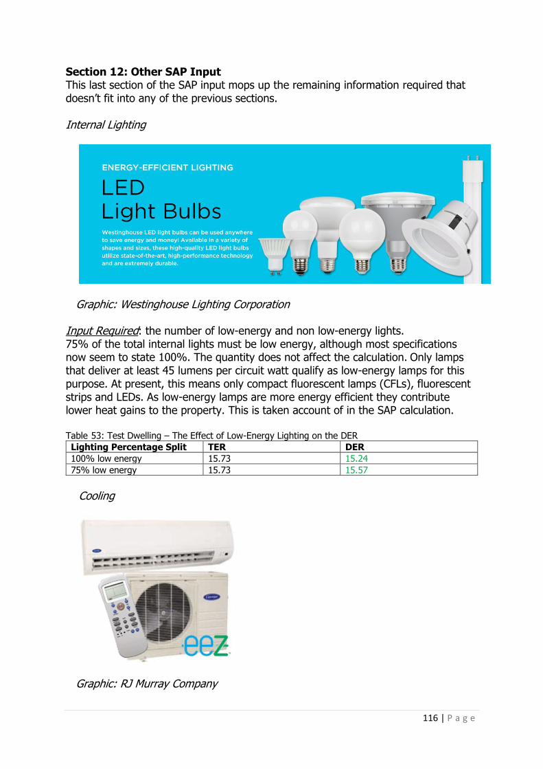
116 | P a g e
Section 12: Other SAP Input This last section of the SAP input mops up the remaining information required that doesn’t fit into any of the previous sections. Internal Lighting
Graphic: Westinghouse Lighting Corporation Input Required: the number of low-energy and non low-energy lights. 75% of the total internal lights must be low energy, although most specifications now seem to state 100%. The quantity does not affect the calculation. Only lamps that deliver at least 45 lumens per circuit watt qualify as low-energy lamps for this purpose. At present, this means only compact fluorescent lamps (CFLs), fluorescent strips and LEDs. As low-energy lamps are more energy efficient they contribute lower heat gains to the property. This is taken account of in the SAP calculation. Table 53: Test Dwelling – The Effect of Low-Energy Lighting on the DER
Lighting Percentage Split TER DER
100% low energy 15.73 15.24
75% low energy 15.73 15.57
Cooling
Graphic: RJ Murray Company

117 | P a g e
Input Required If mechanical cooling is to be installed, this will not alleviate any summer overheating warning (see next Section for more details), and also does not affect the summer overheating calculation.
However, Cooling can affect the Fabric Energy Efficiency calculation. The cooling load of a dwelling is affected by the Thermal Mass Parameter (TMP), the Heat Loss Parameter (HLP), the Degree Day Region and the level of heat gains in summer. Further information about the cooling calculation in SAP can be found in SAP 2012 Version 9.92 (October 2013), Section 10.
The Data can either be the SAP Default or declared for the EER (Energy Efficiency
Ratio) and SEER (Seasonal Energy Efficiency Ratio) figures.
The Cooled area m2 is required: this is the floor area of the rooms to be cooled as
it may not be the whole dwelling. Energy Label Class: between A–G or unknown; if using the SAP Default option,
this will determine the EER/SEER efficiency figures. Air Conditioning Controls: either on/off or Variable Speed Compressor; these will
also determine the EER/SEER efficiency figures. SAP 2012 Version 9.92 (October 2013), Table 10c: EER and SEER have further
details of what these figures are. If the Manufacturer Declared option is selected then the only input is the EER and
the control type, in addition to the area to be cooled. Most of the input has very little effect on the DER, except for the area m2, the
fewer m2 requiring cooling the better. The lowest DER comes from the lower floor area, combined with a Split or Multi-
split system, an Energy Labelling class of A, with a variable speed compressor. Appendix Q
Appendix Q is sort of a holding area before technologies are taken into the PCDB.

118 | P a g e
It currently has three technologies for use in SAP 2012: • Dynamic Insulation
• Solar Air Positive Input Ventilation • Solar Assisted Heat Pumps To use any of these in the SAP calculation, the appropriate Appendix Q worksheet
needs to be completed to derive the appropriate figures to enter into the calculation.
For the purpose of this document I am not going to explain the above any further, as so far in all the calculations I have undertaken, none of these technologies have been specified.
Summary of Section 12 The number of internal lights and the presence of Cooling is not going to make a significant impact on the DER and, therefore, it is more a matter of inputting the correct information, and ensuring that both meet the minimum requirements of Part L1A. For lighting, a minimum of 75% of the total is dedicated low energy and, for any cooling equipment, the minimum efficiencies are achieved.

119 | P a g e
PART THREE This Part of the book summarises the main requirements of Part L, its relationship to the Approved Document AD L1A, and also its link to SAP 2012.
What is Part L1A? Below is the Requirement from the Building Regulations, the text copied verbatim to avoid any confusion. It’s here because the Regulation itself is very simple, and the Approved Document is the usual way of complying with this, demonstrated by undertaking a SAP calculation and providing the various outputs from that calculation as evidence to show compliance.
Schedule 1: Part L Conservation of fuel and power
L1. Reasonable provision shall be made for the conservation of fuel and power in buildings by:
(a) Limiting heat gains and losses: (i) Through thermal elements and other parts of the building fabric; and (ii) From pipes, ducts and vessels used for space heating, space cooling and hot
water services; (b) Providing fixed building services which: (i) Are energy efficient; (ii) Have effective controls, and; (iii) Are commissioned by testing and adjusting as necessary to ensure they use
no more fuel and power than is reasonable in the circumstances.

120 | P a g e
What buildings are covered in Part L1A? Appendix B in the Approved Document (ADL Part L1A)
- Construction of new dwellings - Live work units If a unit contains both living accommodation and space to be used for commercial
purposes, the whole building should be treated as a dwelling as long as the commercial could revert to domestic use. That doesn’t mean that a small flat in a large office can be treated as a dwelling!
- Mixed use developments This means that ADL1A is used for the dwellings, and common areas such as
heated corridors, or offices and shops in the same building, come under the guidance in ADL2A. In a block of flats, for example, it’s best from a Part L compliance perspective only that the common corridors and stairwells remain unheated. Otherwise, if heated, they will require a Simplified Building Energy Model (SBEM) calculation to comply with ADL2A, which in many instances can be a problem in just gaining compliance with the BER/TER.
- Material change of use Erecting a new dwelling is not a material change of use, this is only applicable to
existing buildings that are, well, changing use, and therefore ADL1B would be applicable.
Reporting Evidence of Compliance Appendix C in Approved Document (ADL Part L1A)
Once a SAP calculation is complete, the software, no matter which one is used, will have a number of outputs that clearly show all that is required by Building Control to demonstrate compliance with L1A.
There will be two versions, one at completion of the Design Stage, submitted
before any building work starts, and a second within thirty days of completion, detailing the actual As-Built specification.
Building Control may in addition want to see the U-Value calculations and the
design specification to determine them, along with a summary of any performance criteria deemed to be better than would be typical. This is detailed in Appendix C in L1A. As a minimum, Building Control should be provided with:
• The Regulations Compliance report, and • Listing of the input data list, and • Predicted Energy Assessment (PEA) (if design stage) or EPC (if As-Built stage) Building Control should also be supplied with any supporting information that they
may request. The Compliance Report may show a fail under some headings; in these circumstances it is the decision of Building Control as to whether or not they approve the construction.

121 | P a g e
Any differences between the as-designed specification and the As-Built specification should be highlighted on the input data list.
Often an issue that does arise is where the As-Built calculation does differ from
the Design calculation, usually due to changes made throughout the build process. This is not an issue unless the performance criteria input at design stage also changes, for example changes in insulation that affect a U-Value, or a change of heating type. If these changes are not notified to the SAP assessor before physical completion, then there is a high risk the calculation may fail on either or both the DER/TER and DFEE/TFEE. It doesn’t mean to say that by checking the changes and noticing that it fails, the assessor can do anything about it – they are not the designer, after all – but it does mean that the designer will be forewarned and can do something before it’s too late. It sounds obvious, but the number of dwellings I have assessed at As-Built stage that fail due to changes made throughout the build, are too numerous to mention.
What does an assessor do when completing the SAP calculation and providing an EPC?
It is to demonstrate compliance with five Criteria of Part L1A. These are as follows:
- Criterion 1 Achieving the TER and the TFEE The calculated CO2 emission rate for the building (The DER: Dwelling Emission
Rate) must not be greater than the target (TER: Target Emission Rate) and the DFEE (Dwelling Fabric Energy Efficiency Standard) must not be greater than the TFEE (Target Fabric Energy Efficiency). This is the main requirement of Part L1A and is mandatory, so a SAP calculation is required to meet this criterion.
- The other Criteria are, strictly speaking, guidance only. However, the
compliance submission document lists them, and showing a fail would mean that another method of demonstrating compliance would need to be found. It’s a lot simpler, in most respects, to follow the guidance in ADL1A to meet these other Criteria.
- Criterion 2 Limits on design flexibility The performance of the building fabric and the heating, hot water and fixed
lighting systems should achieve reasonable overall standards of energy efficiency. - Criterion 3 Limiting the effects of heat gains in the summer Demonstrate that the building has appropriate passive control measures to limit
solar gains. The purpose here is to reduce the need for installed capacity of air conditioning systems in summer.
Heat losses and gains from circulation pipes Reasonable provision should be made to limit the heat losses from pipes, as set
out in the Domestic Building Services Compliance Guide.
122 | P a g e
- Criterion 4 The performance of the dwelling, as built, should be consistent with the DER.
Essentially, this is dealing with the gap between the performance As-Designed and performance As-Built, often with the latter being lower than expected. It includes information regarding continuity of insulation, air permeability and pressure testing, party walls and other thermal bypasses, and commissioning of heating and hot water systems.
- Criterion 5 Provisions for energy-efficient operation of the building The necessary provisions for enabling energy-efficient operation of the building
should be put in place.
Of the five Criteria above, producing a SAP calculation will cover Criteria 1 and 2 explicitly; and will provide information for the compliance of 3 and 4; but does not cover Criterion 5. Criterion 5 is provision of sufficient information for the owner to operate the dwelling as efficiently as possible. A copy of the As-Built SAP calculation and EPC should be part of this information.
To provide an EPC there are conventions and evidence requirements that must be met. To help with this process I have a SAP As-Built EPC Checklist; see Appendix 5. I ask clients to complete, sign and return this to me with a number of documents noted within the Checklist. This serves two purposes: the first is to tell me what has been constructed, and, if any changes have been made between the design stage and the As-Built stage, what those changes are. Second, it serves to meet the evidence requirements of the EPC, and can also be requested by Building Control to provide evidence for the Building Regulations’ pass criteria.
Apart from the checklist document itself, which is a signed declaration by either
the builder, architect or client, the following documents are required: • As-Built Drawings and Specification • U-Value calculations • Party Wall: confirmation of sealing and filling • BRFC or other documentation stating U-Value and G-Value
• TMP Calculations (as appropriate) • Thermal Bridging Psi Value Calculations (as appropriate) • Thermal Bridging: signed ACD or other on site checklists • Air Test Certificate • Commissioning Certificates or other written documentation for all items in the
Product Database • MCS or other commissioning certificates for Heat Pumps, Solar Thermal and
Solar PV
What is actually required to gain compliance: The Details DER (Dwelling Emission Rate) and TER (Target Emission Rate) This is the main one. If the TER is higher than the DER, the dwelling fails. How you affect the DER is multi-faceted, and having an understanding of what goes into

123 | P a g e
making the TER is also important, so that you know what you are up against. This has been helped by the addition in the latest Approved Document of a Model Dwelling Criteria (see Part One, above, for full details).
The DER is derived from the design input that also goes into complying with the other criteria. Achieving target U-Values, air permeability figures, system efficiencies and type of heating, hot water, lighting etc all impact on the DER figure, of course.
The DER and TER is a measure of the CO2 emitted annually, per square metre:
kgCO2/m2/year.
DFEE (Dwelling Fabric Energy Efficiency) and TFEE (Target Fabric Energy Efficiency) Since the change in Building Regulations in April 2014, this is the second mandatory target that must be achieved, in addition to the TER, to demonstrate compliance.
The DFEE is calculated from the SAP input of U-Values, Air Permeability, Thermal Bridging and Ventilation, and the DFEE must be equal to or lower than the TFEE.
The DFEE and TFEE are a measure of the energy demand annually, per square
metre: kWh/m2/year. The National Calculation Methodology (NCM), for Part L1A, is SAP 2012, and
determines the TER/TFEE. It’s based on minimum standards being met for thermal performance and a minimum set of efficiencies for the Mechanical and Electrical services as detailed for the Model Dwelling.
The TER/TFEE is based on a dwelling that is the same size and shape as the
actual dwelling, constructed to a specification as detailed in SAP 2012. When we talk about the TER, this is the Notional Dwelling or Model Dwelling. If you see Model Dwelling, as mentioned in ADL1A, Notional Dwelling, or TER, they are all in effect the same thing. The Model/Notional Dwelling is the dwelling whose performance is expressed as the TER and TFEE.
It is useful to know what affects the TER/TFEE, particularly when determining
what U-Values or air permeability the dwelling should be, amongst other information, because the values given to the Notional Dwelling are not the same as those as minimum standards in ADL1A. In most cases they are lower in the Notional Dwelling, so, for example, you may have thought achieving a U-Value of 0.20 for the roof would be ok, but the Notional Building has a U-Value of 0.13. That’s a considerable difference in performance.
124 | P a g e
SAP 2012 (NCM) and The TER
The Notional Dwelling The TER/TFEE is determined by the performance of the Notional Building.
The Notional Dwelling is automatically determined by the information input to the SAP calculation as follows:
• The dwelling will have the same size and shape as the actual dwelling • It will have the same orientation as the actual dwelling, and have the UK
average weather data applied • Living Area, the same as the actual dwelling • Sheltered sides, the same as the actual dwelling
• Any heating, ventilation and cooling attributed to a zone in the actual building will be mirrored in the Notional
The Actual Dwelling, the one As-Designed, will be input using the information
provided by the designer, using plans and specifications. However, in many situations, the information – particularly at design stage – is not always known, although this does also occur at the As-Built stage – which, frankly, surprises me. Don’t they know what they built it from? Anyway, if information is not available, we have to accept the use of SAP Default figures. These are usually nowhere near as good as those actually installed, and certainly a dwelling will not pass if relying only on these Defaults. This has been demonstrated throughout Part Two of this book.

125 | P a g e
The full SAP Default Values are given in SAP 2012 Version 9.92 (October 2013). To illustrate the difference between the Notional Building, Building Regulations’
maximums, and the Defaults used in SAP, I have compared them throughout the next section.
Notional Dwelling Specification If the Notional Dwelling specification were input into SAP 2012, the dwelling would normally pass both the DER/TER and the DFEE/TFEE. In the Approved Document L1A, Section 5 Model Design, Table 4, there is an abbreviated specification for the Notional Dwelling, with a full specification listed in the SAP 2012 Version 9.92 (October 2013), Appendix R.
Opening Areas: these will be the same as the actual dwelling, up to a maximum of 25% of the total floor area. If the proposed area is over 25%, then those additional heat losses caused by the over glazing, glazing and doors having a higher U-Value than for walls and roofs, for example, will need to be made up for elsewhere in the design. It is worth mentioning now that this will be the same for any of the input that is ‘worse’ than the Notional Dwelling; it will need to be accounted for somewhere.
External Walls: Notional Dwelling U-Value of 0.18. Building Regulations’ maximum is 0.3. No Default Value in SAP. Party Walls: Notional Dwelling U-Value of 0.0 either a solid party wall, or a fully-filled and sealed cavity wall. Building Regulations’ maximum is 0.2, sealed but not fully filled. In SAP there is an option to input unfilled and unsealed, which gives a Default of 0.5. Floor: Notional Dwelling U-Value of 0.13. Building Regulations’ maximum is 0.25. No Default Value in SAP. Roofs: Notional Dwelling U-Value of 0.13. Building Regulations’ maximum is 0.20. No Default Value in SAP. Windows, roof windows, glazed roof lights and glazed doors: Notional Dwelling U-Value of 1.4. Building Regulations’ maximum is 2.0. In SAP there are variations in the Default Values depending on the types of window/door/roof windows that are input. For example, a double-glazed UPVC window, argon filled, low e soft coated using Default Values for both frame factor and G factor will be 1.8. Opaque doors <30% glazed: Notional Dwelling U-Value of 1.0. Building Regulations’ maximum is 2.0. SAP Default U-Value of 3.0.

126 | P a g e
Semi-glazed doors 30%–60% glazed; Notional Dwelling U-Value of 1.2. Building Regulations’ maximum is 2.0. SAP Default U-Value of 2.4. Curtain Walling: same area as the actual dwelling. If above 25% of the floor area, the glazed area is reduced to 25%, and the opaque sections have a U-Value of 0.18 and the glazed areas a U-Value of 1.5. Building Regulations is 2.0. No Default Value in SAP. Air Tightness: Notional Dwelling is 5m3/(h.m2) Building Regulations: 10m3/(h.m2). If an exemption is applied, the Default in SAP is 15m3/(h.m2). This is based on an air permeability of 15 divided by a shelter factor plus infiltration from fans, flues and chimneys. If no exemption and no target is input, SAP determines a figure based upon infiltration from the structure type, windows, fans, flues and chimneys as input. This can give a better result in the DER/DFEE than if an exemption were applied. Linear Thermal Transmittance (Non-Repeating Thermal Bridging): the Notional Dwelling uses the lengths as calculated and the Default Ψ-Values from SAP Appendix R. These are the same values as a Default in SAP. The Ψ-Values can only be changed to much-improved values if Accredited Construction Details or other similar Approved Details are used. The total value of these will usually be much lower than 0.15 W/m2K. If the actual building uses a total figure of y=0.15 W/m2K, the Notional will use 0.05 W/m2K. If the window area is over 25% of the floor area, the lengths for linear Thermal Bridging in the Notional will be the same as calculated for the actual, even though the window area in the Notional will only be 25% of the floor area. Thermal Mass Parameter (TMP): Medium. There is no Building Regulations requirement. Ventilation Type: natural, with extract fans as follows: 2 fans for up to TFA 70m2 3 fans for up to TFA >70–100m2 4 fans for TFA >100m2. There is no minimum number required under Part L, although there is under Part F. There is no Default number in SAP. Chimneys, Open Flues and Air Conditioning: none Main Heating System: Notional Dwelling assumes mains gas, combi or regular boiler of 89.5% efficiency to radiators, with a room-sealed fan flue. Building Regulations’ minimum efficiency is 88%. SAP Default for a gas combi or regular boiler is 87% efficiency.
127 | P a g e
In the proposed dwelling if a system other than a gas boiler is input the Notional building will still be the boiler, as above. However, depending on which system is input (electric heating, wood boiler, LPG boiler, etc) will determine how it performs against a gas boiler. If electric heating, this is invariably worse; if a heat pump, or wood boiler, for example, it’s usually much better. This is because of the varying fuel factors and emissions factors associated with the different fuel types. Main Heating Controls: the Notional assumes Time and Temperature zone control, weather compensation and modulating boiler with interlock. Unless a single-storey dwelling where the living area is greater than 70% of the total floor area, a programmer and room stat. Hot water storage system: the Notional will assume DHW heated by the main system with the same volume as the specified cylinder, if present. A cylinder will be in a heated space, thermostat controlled with separate time control. Primary pipe work fully insulated, and cylinder loss factor equal or better than 0.85 x (0.2+0.051 V 2/3) kWh/day. The Building Regulations’ minimum is 1.15 x (0.2+0.051 V 2/3) kWh/day, where V is the volume of the cylinder. Secondary Heating: none Low-Energy Lighting: 100%. The Building Regulations’ minimum is 75% low energy.
SAP Calculation Methodology The SAP 2012 Version 9.92 (October 2013) document details how the SAP Software will calculate the SAP result and produce the resulting compliance documents. There is little to be gained by repeating that document here. I have repeated the introductory summary below as this details exactly what SAP is and what it does.
This manual describes the Government’s Standard Assessment Procedure (SAP) for assessing the energy performance of dwellings. The indicators of energy performance are Fabric Energy Efficiency (FEE), energy consumption per unit floor area, energy cost rating (the SAP rating), Environmental Impact rating based on CO2
emissions (the EI rating) and Dwelling CO2 Emission Rate (DER). The SAP rating is based on the energy costs associated with space heating, water
heating, ventilation and lighting, less cost savings from energy-generation technologies. It is adjusted for floor area so that it is essentially independent of dwelling size for a given built form. The SAP rating is expressed on a scale of 1–100; the higher the number the lower the running costs.
The Environmental Impact rating is based on the annual CO2 emissions associated
with space heating, water heating, ventilation and lighting, less the emissions saved by energy-generation technologies. It is adjusted for floor area so that it is essentially independent of dwelling size for a given built form. The Environmental Impact rating is expressed on a scale of 1–100; the higher the number the better the standard.

128 | P a g e
The Dwelling CO2 Emission Rate is a similar indicator to the Environmental Impact rating, which is used for the purposes of compliance with Building Regulations. It is equal to the annual CO2 emissions per unit floor area for space heating, water heating, ventilation and lighting, less the emissions saved by energy-generation technologies, expressed in kg/m²/year.
The method of calculating the energy performance and the ratings is set out in
the form of a worksheet, accompanied by a series of tables (see Appendix 2). The methodology is compliant with the Energy Performance of Buildings Directive. The calculation should be carried out using a computer programme that implements the worksheet and is approved for SAP calculations (BRE approves SAP software used within schemes recognised by Government on behalf of the Department for Energy and Climate Change; the Department for Communities and Local Government; the Scottish Government; the National Assembly for Wales; and the Department of Finance and Personnel).

129 | P a g e
SAP Output Documents Building Regulations
L1A Compliance Document: details of the compliance with the five Building Regulations’ criteria (including those not directly produced from the SAP assessment) in accordance with the Part L1A document.

130 | P a g e
DER Worksheet
This provides a version of the SAP Worksheet completed with the details used to calculate the DER (which are slightly different to the details used for the SAP). This is part of the Part L1A assessment expressed as DER kg CO2/m2/year and Variance against the TER as a percentage.

131 | P a g e
DER Worksheet Contents: • Overall Dwelling Dimensions • Ventilation Rate • Heat Losses and Heat Parameter • Water Heating Energy Requirement • Internal Gains
• Solar Gains • Mean Internal Temperature • Space Heating Requirement • Energy Requirements • Fuel Costs
• SAP Rating • CO2 Emissions • Primary Energy

132 | P a g e
DFEE Worksheet
This provides a version of the SAP Worksheet completed with the details used to calculate the DFEE. This is part of the Part L1A assessment expressed as DFEE kWh/m2/year and Variance against the TFEE as a percentage.

133 | P a g e
DFEE Worksheet Contents: • Overall Dwelling Dimensions • Ventilation Rate • Heat Losses and Heat Parameter • Water Heating Energy Requirement • Internal Gains
• Solar Gains • Mean Internal Temperature • Space Heating Requirement • Space Cooling Requirement • Fabric Energy Efficiency DFEE

134 | P a g e
SAP Worksheet – SAP 2012 Assessment – Determines the SAP Rating, Environmental Impact (EI)
135 | P a g e
Rating from the CO2 emissions. The SAP rating scale has been set so that SAP 100 is achieved at zero-ECF. It can rise above 100 if the dwelling is a net exporter of energy. The SAP rating is essentially independent of floor area.
Energy efficiency rating bands are defined by the SAP rating according to Table
14. The EI rating scale has been set so that EI 100 is achieved at zero net emissions.
It can rise above 100 if the dwelling is a net exporter of energy. The EI rating is essentially independent of floor area.
Environmental impact rating bands are defined by the EI rating according to Table 14.
SAP 2012 version 9.92 (October 2013), Table 14: rating bands The rating is assigned to a rating band according to the following Table. It applies
to both the SAP rating and the Environmental Impact rating.
Rating Band 1–20: G 21–38: F 39–54: E 55–68: D 69–80: C 81–91: B 92 or more: A CO2 emissions attributable to a dwelling are those for space and water heating,
ventilation and lighting, less the emissions saved by energy-generation technologies. These are expressed as CO2 Emissions Kg CO2/year and CO2 Emissions Rate Kg CO2/m2/year. SAP Worksheet contents:
• Overall Dwelling Dimensions • Ventilation Rate • Heat Losses and Heat Parameter • Water Heating Energy Requirement • Internal Gains • Solar Gains
• Mean Internal Temperature • Space Heating Requirement • Energy Requirements • Fuel Costs • SAP Rating
• CO2 Emissions • Primary Energy

136 | P a g e
Predicted Energy Assessment (at Design Stage Only)
The PEA can be given to the prospective householder when a dwelling is marketed from plans and later replaced by the EPC.

137 | P a g e
Energy Performance Certificate (Upon Completion Only)
An EPC can be produced from an As Built Final record; all EPCs are valid for a maximum of ten years. After that time a new EPC must be produced when the property is next offered for sale on the open market. This new EPC has to be produced using the procedure for existing homes, i.e. RDSAP (Reduced Data SAP).
The Predicted Energy Assessment (PEA) is appropriate for all developers selling dwellings off-plan. PEAs should be replaced with an EPC once the dwelling is physically complete.

138 | P a g e
A dwelling is deemed ‘physically complete’ when all the following conditions are met:
a) Commissioning of the heating system has been satisfactorily completed, and b) Accredited details are signed off, and c) Air permeability is confirmed via pressure testing of representative dwellings,
and d) The dwelling itself is complete and could be pressure tested. It is the developer’s responsibility to use the PEA until a dwelling is physically
complete, at which time they should feed information about changes from the Design Stage to the As Built stage to the On Construction Domestic Energy Assessor (OCDEA), so that an EPC can be produced. You should not produce an EPC without such information. However, you may find you need to prompt the developer to produce the required information.
Provide a copy of the EPC to the client (in electronic or paper form) as well as the
Report Reference Number (RRN), to be passed to the Building Control body.

139 | P a g e
Assessors, Accreditation Schemes and The Rules We Have to Follow Assessors must complete a training course using their chosen SAP modelling tool, pass an exam, submit several dwellings for assessment and, once passed, can practice as an Approved Assessor. They must also belong to an Approved Accreditation Scheme and follow each scheme’s Code of Conduct, have appropriate insurance, and carry out a prescribed number of hours of Continuing Personal Development each year.
There is one level of competence for an OCDEA: assessors can only produce Energy Performance Certificates (EPCs) for new dwellings and existing buildings that have been part of an L1B calculation.
SAP Assessors/OCDEAs are the only assessors who can produce Part L1A/L1B
compliance checks and EPCs on both existing and new Dwellings. A Domestic Energy Assessor can provide EPCs on existing dwellings only that are for sale or rent, and to do so they use the RDSAP software. There is a Reduced Data version of the full SAP, which allows for on-site data collection/assessment of the dwelling and cannot be used for Building Regulations compliance. As such, the training and competences of the two streams of assessors are different, and both require separate training, examination and certification before carrying out assessments. About The Author We set up Energy Saving Experts in 2007, and I have been producing calculations and reports for all aspects of Part L for several years, working with Architects and Building Control bodies providing guidance and training in all aspects of Part L, and work with them to help clients gain compliance. It’s important to me that the result is the best that is achievable, and not just a pass to gain compliance minimums; if you are going to do the job you may as well do it to the best possible standard.
I am qualified to produce SAP calculations and EPCs as an OCDEA for domestic work for compliance with L1A and L1B.
I am also qualified to provide level 4 Non-Domestic Energy assessments and EPCs
using SBEM, and am a Public Building Assessor able to produce Display Energy Certificates (DECs). I have worked on hundreds of buildings of all types, from single flats to over a hundred houses in a single development; from tower blocks, warehouses and retail shops to very large office buildings and factories.
I also provide several calculations for Planning purposes, and will soon bring
together both surveying and assessment services to offer a service for energy efficient retrofit of existing buildings.
Life outside of work is either walking and cycling, an ongoing creation of a wildlife
garden, family life, Bath Rugby, and some would say an unhealthy obsession with the music of Miles Davis.
A proportion of the profits from this book will go to the Bumblebee Conservation
Trust.

140 | P a g e
Appendices Appendix 1: Organisations Providing Thermal Bridging PSI Values Concrete Block Association: www.cba-blocks.org.uk/tech/thermal-bridge.html

141 | P a g e
LABC Construction Details: www.labc.co.uk/registration-schemes/construction-details

142 | P a g e
Enhanced Construction Details: Energy Saving Trust http://tools.energysavingtrust.org.uk/Organisations/Technology/Free-resources-for-housing-professionals/New-build/Enhanced-construction-details

143 | P a g e
AECB Silver and Gold Details: http://www.aecb.net/publications/thermal-bridges/

144 | P a g e
Scottish ACDs, available from the Scottish Government Website (can also be used in England): http://www.gov.scot/Topics/Built-Environment/Building/Building-standards/publications/pubtech/techaccconstrdetails
There are various Manufacturers’ own details too, including the following: Kingspan TEK: www.kingspantek.co.uk Kingspan will provide many details upon request.

145 | P a g e
Xtratherm: http://www.xtratherm.com/technical-information/thermalbridging

146 | P a g e
Logix: http://www.logix.uk.com/icfs_benefits_fact_sheet.html

147 | P a g e
As can be seen from the above examples, there are hundreds of details available that have been verified to use in the User Defined category, and probably as many that can be found on the internet that have not. Always look for psi values that have been calculated by a person with suitable expertise and experience using the guidance set out in ‘BR 497, Conventions for calculating linear thermal transmittance and temperature factors’ and ‘BRE IP 1/06, Assessing the effects of thermal bridging at junctions and around openings’.
Upon searching out details, there are also those that do not appear in Appendix K1, above. For example, the Scottish ACDs list one for a loft hatch (see below). This cannot be used in the SAP calculation in the Thermal Bridging screen, but would be good evidence to demonstrate that the loft hatch is insulated. Not only is this good practice, but it is used as a correction in a roof U-Value calculation.

148 | P a g e
Appendix 2: List of Tables Table 1: Model Dwelling England (TER/TFEE) Values Compared to Part L Regulations Table 2: Test Dwellings – SAP Results Using the Model Dwelling Values from Table 1 Table 3: Indicative Constructions to Determine the Thermal Mass of a Dwelling Table 4: Test Dwellings – Difference in DER Compared to the TER by Changing the Thermal Mass Parameter (TMP) Table 5: Test Dwellings – Difference in DFEE Compared to the TFEE by changing the Thermal Mass Parameter (TMP) Table 6: Test Dwellings – DER/TER Percentage Variance Depending on the Number of Sheltered Sides, to Dwelling Type Table 7: Test Dwellings – DFEE /TFEE Percentage Variance Depending on the Number of Sheltered Sides, to Dwelling Type Table 8: Test Dwellings – DER/TER Percentage Variance Depending on Dwelling Orientation, to Dwelling Type Table 9: Test Dwellings – DFEE/TFEE Percentage Variance Depending on Dwelling Orientation, to Dwelling Type Table 10: Test Dwelling – The Effect of Floor Area and Dwelling Storey Height on the DER Table 11: Test Dwelling – The Effect of Zone 1 Area on the DER Table 12: Test Dwellings – The Effect on the DER/DFEE of Ground Floor U-Values of the Notional U-Values Compared to Part L Maximum U-Values Table 13: Test Dwelling (Mid Terrace) – The Effect on the DER and DFEE With Different Party Wall Constructions Table 14: Test Dwellings – The Effect on the DER/DFEE of External Wall U-Values of the Notional U-Values Compared to Part L Maximum U-Values Table 15: Test Dwellings – The Effect on the DER/DFEE of Roof U-Values of the Notional U-Values Compared to Part L Maximum U-Values Table 16: The Effect of Emissivity on Overall Window U-Value Table 17: Overshading Definition used in SAP Table 18: Test Dwelling – The Effect on the DER/DFEE of Window U-Value Options in SAP Table 19: Test Dwelling – The Effect on the DER/DFEE of Window G-Value Options in SAP Table 20: Default and Approved Y-Values and Their Effect on the DER and DFEE Table 21: Test Dwellings – The Effect of Various Air Test Results on the DER Table 22: Test Dwellings – The Effect of Various Air Test Results on the DFEE Table 23: Test Dwellings – The Effect of Various Mechanical Ventilation Systems on the DER and DFEE Table 24: Test Dwellings – The Effect of Extract Fans on the DER/DFEE Table 25: Test Dwellings – The Effect of Passive Vents on the DER/DFEE Table 26: Test Dwellings – How Open Fires Affect DER and the DFEE Table 27: Test Dwellings – How Open Flues Affect DER and the DFEE Table 28: Test Dwellings – How Flueless Gas Fires Affect DER and the DFEE Table 29: Test Dwelling – Comparing the DER with Secondary Heating, Specified and not Specified, Where There is an Open Flue or Chimney Table 30: Test Dwelling – The Effect of Boilers Selected From Either SAP Default or the Product Database on DER Table 31: Test Dwelling – The Effect of Different Boiler Control Options on the DER

149 | P a g e
Table 32: Test Dwelling – The Effect on the DER of the Presence of a Delayed-Start Thermostat Table 33: Test Dwelling – The Effect on the DER of the Presence of a Weather or Load Compensator Table 34: Test Dwelling – The Effect on the DER of Different Emitter Types Table 35: Test Dwelling – The Effect of a FGHRS on a Boiler System Table 36: Fuel Emissions Factors Used in SAP Table 37: Test Dwelling – The Effect of Boiler Fuel Type on the DER. Table 38: Test Dwelling – The Effect of Boiler and Electric Heating Options on the DER, in the Same Dwelling. Table 39: Test Dwelling – The Effect on the DER of Changes in DHW Cylinder Specification Table 40: Test Dwelling – The Effect on the DER Comparing DHW Cylinder, Thermal Store and CPSU Table 41: Test Dwelling – The Effect on the DER of Various WWHRS Table 42: Test Dwelling – The Effect on the DER of Various Types of Solar Thermal Systems Table 43: Test Dwelling – The Effect on the DER of Orientation of Solar Thermal Systems Table 44: Test Dwelling – The Effect on the DER of Inclination of Solar Thermal Systems Table 45: Test Dwelling – The Effect on the DER of Overshading of Solar Thermal Systems Table 46: Test Dwelling – The Effect on the DER of Gross M2 of Solar Thermal Systems Table 47: Test Dwelling – The Effect on the DER of Various Solar Pump Power of Solar Thermal Systems. Table 48: Test Dwelling – The Effect on the DER of Various Shower/Bath Combinations and Solar Thermal Systems Table 49: Test Dwelling – The Effect on the DER of Orientation of a Solar PV System Table 50: Test Dwelling – The Effect on the DER of Inclination of a Solar PV System Table 51: Test Dwelling – The Effect on the DER of Overshading of a Solar PV System Table 52: Test Dwelling – The Effect on the DER of Varying kWp of a Solar PV System Table 53: Test Dwelling – The Effect of Low-Energy Lighting on the DER

150 | P a g e
Appendix 3: SAP 2012 version 9.92 (October 2013), Reference Tables The Reference Tables in the above SAP Document are listed below. These are invaluable for a full understanding of the input used in SAP, particularly the Default Value so often referred to throughout the book. Table 1a: Number of days in month: nm Table 1b: Occupancy and domestic hot water usage Table 1c: Monthly factors for hot water usage Table 1d: Temperature rise of hot water drawn off (DTm, in K) Table 1e: Heat capacities for some common constructions Table 1f: Thermal mass parameter Table 2: Hot water storage loss factor 135 Table 2a: Volume factor for cylinders and storage combis 135 Table 2b: Factors applied to losses for cylinders, thermal stores and CPSUs, and storage combi boilers not tested to EN 13203-2 or OPS 26 136 Table 3: Primary circuit loss 137 Table 3a: Additional losses for combi boilers not tested to EN 13203-2 or OPS 26 137 Table 3b: Losses for combi boilers tested to EN 13203-2 or OPS 26, schedule 2 only 138 Table 3c: Losses for combi boilers tested to EN 13203-2 or OPS 26, two schedules 139 Table 4a: Heating systems (space and water) 140 Table 4b: Seasonal efficiency for gas and oil boilers 145 Table 4c: Efficiency adjustments 146 Table 4d: Heating type and responsiveness for wet systems depending on heat emitter 147 Table 4e: Heating system controls 148 Table 4f: Electricity for fans and pumps and electric keep-hot facility 151 Table 4g: Default specific fan power for mechanical ventilation systems and heat recovery efficiency for MVHR systems 152 Table 4h: In-use factors for mechanical ventilation systems 152 Table 5: Internal heat gains 153 Table 5a: Gains from pumps and fans 153 Table 6b: Transmittance factors for glazing 154 Table 6c: Frame factors for windows and glazed doors 154 Table 6d: Solar and light access factors 154 Table 6e: Default U-Values (W/m2K) for windows, doors and roof windows 155 Table 9: Heating periods and heating temperatures 157 Table 9a: Utilisation factor for heating 157 Table 9b: Temperature reduction when heating is off 158 Table 9c: Heating requirement 158 Table 10a: Utilisation factor for cooling 160 Table 10b: Cooling requirement 160 Table 10c: Energy Efficiency Ratio (EER) and System Energy Efficiency Ratio (SEER) 161 Table 11: Fraction of heat supplied by secondary heating systems 162 Table 12: Fuel prices, emission factors and primary energy factors 163 Table 12a: High-rate fractions for systems using 7-hour and 10-hour tariffs 165

151 | P a g e
Table 12b: Solid Fuels 166 Table 12c: Distribution loss factor for group and community heating schemes 167 Table 13: High-rate fraction for electric DHW heating 168 Table 14: Rating bands 169 Table 15: Relationship between SAP 2009 ratings and SAP 2012 ratings 169 Table 16: Relationship between Environmental Impact ratings, SAP 2009 and SAP 2012 170

152 | P a g e
Appendix 4: New Build Checklist – to be used at Design Stage to provide required information for the SAP Calculation.
New Build Checklist To enable us to complete your energy assessment we will require: 1) This completed Checklist 2) Drawings: Floor Plans, Internal Sections and External elevations (scale 1:100, 1:50), PDF preferable. 3) Window and Door schedule 4) Site layout and location plan showing orientation Please complete this checklist in full. JOB NUMBER: _______________________________________________________________ PROJECT DETAILS: _______________________________________________________________ Person Completing this Checklist: _______________________________________________________________ Date: _______________________________________________________________ Name and Signature: _______________________________________________________________ Email and contact phone number: _______________________________________________________________ Site Address and Postcode: _______________________________________________________________ _______________________________________________________________ INVOICE DETAILS: Company Name: _______________________________________________________________ Contact Name: _______________________________________________________________ Telephone: _______________________________________________________________ Email:

153 | P a g e
_______________________________________________________________ PAYMENT DETAILS: BACS transaction: ________________BACS reference:___________________ BACS date and amount: ____________________ ___________________________________________ (Co-operative Bank sort code: 08-92-50. Energy Saving Experts Ltd account: 68007045) Cheque enclosed: _________________Name on cheque:__________________ TIMESCALE: Has this project already been submitted to Building Control? Yes / No Date: ____ ___________________________________________________________ Estimated completion date of build: ____________________________ ___________________________________ Energy Performance Certificate required? ________________________________ _______________________________ Please provide the following information: If not enough space, please use another sheet if necessary. 1. Ground floor construction Floor covering (e.g. screed) Floor covering thickness (mm) Insulation type Insulation thickness (mm) Floor type (e.g. Block and Beam)
Enter details or provide drawing/specification reference number:

154 | P a g e
2. Other floor type Floor covering (e.g. screed) Floor covering thickness (mm) Insulation type Insulation thickness (mm) Floor type (e.g. Block and Beam) 3. Main wall structure Outer Skin (e.g. brick) Cavity Cavity width (mm) Insulation type Insulation thickness (mm) Inner skin (e.g. Celcon solar block) Finish (e.g. Plasterboard on dabs) 4. Secondary wall type (E.g. Stud walls, wall between garage and dwelling, dormer cheeks) Outer Skin (e.g. brick) Cavity width (mm) Insulation type and thickness (mm) Inner skin (e.g. Celcon solar block) Finish (e.g. Plasterboard on dabs)
Enter details or provide drawing/specification reference number:
Enter details or provide drawing/specification reference number:
Enter details or provide drawing/specification reference number:

155 | P a g e
5. Party wall types (if applicable) Please tick which apply: Solid / Unfilled cavity with unsealed edges / Unfilled cavity with sealed edges / Fully filled cavity with sealed edges
6. Roof construction Habitable area in roof space? Yes / No Warm Roof / Cold Roof Cavity Insulation type and thickness (mm) Finish (e.g. Plasterboard) 7. Other roof type Habitable area in roof space? Yes / No Warm Roof / Cold Roof Cavity Insulation type and thickness (mm) Finish (e.g. Plasterboard)
Enter details or provide drawing/specification reference number:
Enter details or provide drawing/specification reference number:

156 | P a g e
8. Glazing Please circle all that apply: Casement / sash windows etc Air gap: 6mm / 12mm / 16mm / 16mm + Single / Double / Triple UPVC / Timber / Metal / Aluminum Low E ‘soft coat’ / Low E ‘hard coat’ / Argon filled U-Values: Are perforated base plate metal lintels used? Yes / No For metal windows only: Thermal break: None / 4mm / 8mm / 12mm / 20mm / 32mm Roof windows: Air gap: 6mm / 12mm / 16mm / 16mm + Single / Double / Triple UPVC / Timber / Metal / Aluminum Low E ‘soft coat’ / Low E ‘hard coat’ / Argon filled U-Values: 9. External doors Please circle all that apply: Front: solid / half glazed / fully glazed Side: solid / half glazed / fully glazed Rear: solid / half glazed / fully glazed U-Values: 10. Ventilation Number of low-energy extraction fans: ___________ Number of standard extraction fans: ____________ Whole House Mechanical ventilation system: Yes / No If yes, what type of system? Please circle all that apply: Balanced with heat recovery / Balanced without heat recovery / Centralised extract Positive input from loft / Positive input from outside / Decentralised whole house extract Ductwork insulated / uninsulated Rigid / flexible ductwork

157 | P a g e
Manufacturer/Product Name/Details: ________________________________________________________________ ________________________________________________________________ 11. Main Heating System Fuel: _____________________ Model: ________________________________ Manufacturer: ________________________________________________________________ Radiators / Underfloor Heating / Both If a Heat Pump is being installed, please circle all that apply: Air to water / Ground to water / Ground to water with auxiliary heater / Water to water 12. Heating control details Please circle all that apply: Programmer / Zone control / Room stat/s/ Thermostatic Radiator valves / Interlock Load compensator / Delayed-Start thermostat / Weather Compensation 13. Flue Gas Heat Recovery Manufacturer/Product Name/Details: ________________________________________________________________ ________________________________________________________________ 14. Secondary heating Manufacturer/Product Name/Details: __________________________________________________________________ Type: _________________________________ Fuel: _______________________ Hetas Approved? Yes / No 15. Electric tariff Please circle all that apply: Standard / off-peak 7 / off-peak 10 / 24 hour 16. Hot water Is it from the central heating boiler? Yes / No Is it separately timed? Yes / No If No, what system is used for water heating? ________________________________________________________________

158 | P a g e
17. Waste Water Heat Recovery System Manufacturer/Product Name/Details: ________________________________________________________________ ________________________________________________________________ 18. Cylinder Capacity (litres): Insulation thickness (mm): Unventilated: Yes / No Thermal Store? Integrated or Hot Water Only: Immersion: Yes / No Thermostat: Yes / No Primary pipework insulated? Yes / No 19. Water Use < 125 litres / person / day? Yes / No (We can provide the approved Part G water use calculations for you for an additional charge of £35. Contact us for a list of requirements) 20. Lighting Total number of standard light fittings: __________________________________ Total number of low ‘E’ lights: __________________________________________ 21. Air Test If Design Stage SAP – Projected air permeability rate: … m3/hm2(@50Pa) _______ Seek exemption < 3 dwellings? Yes / No If As-Built SAP: Measured Air permeability rate … m3 / hm2(@50Pa)________________________ As-Built ref: ________________________________________________________ As-Built test date: ___________________________________________________ Please include a copy of the certificate. 22. Thermal Bridging All Thermal Bridge lengths will be calculated. If Accredited Construction Details are to be used, the appropriate ACD reference checklists must be supplied before these Values can be input into the final As-Built SAP calculation. For Design Stage, please supply ACD reference numbers. Thermal Mass: is this building Low / Medium / High

159 | P a g e
23. Renewable Technology Please tick all that apply: a) Solar Water Heating Collector type: Evacuated tube / Flat Plate glazed / Flat Plate unglazed Area of collectors: m2 (gross or net) Orientation: N / NE / E / SE / S / SW / W / NW Evacuated tube / Flat plate Glazed / Unglazed Connected to hot water tank? Yes / No Dedicated solar store volume? Litres: _____________________________________ Other details, if known, e.g. collector efficiency (0), heat-loss efficiency (a1):
____________________________________________________________________ ____________________________________________________________________ Solar circulating pump? No / PV powered / electrically powered b) Photovoltaic Panels Installed Peak Power (kWp) Orientation: N / NE / E / SE / S / SW / W / NW c) Micro Wind Turbines Total Number: Rotor Diameter (cm): Height above ridge (m): d) Small Scale Hydro Electricity generated: ________________ kWh/yr Other details: __________________________________________________________________ IMPORTANT NOTICE: calculations are provided subject to the correct information being supplied. Energy Saving Experts Ltd will accept no responsibility for incorrect calculations caused by provision of inaccurate information and plans not to scale. To produce an EPC, all information input into the SAP calculation must be verifiable by documentary evidence. This Checklist and the drawings

160 | P a g e
supplied are part of that process. Should you require any assistance with this Checklist, please contact us at: [email protected] 0791 215 9195 01225 862266 When completed, send to: [email protected]
161 | P a g e
Appendix 5: As Built SAP Checklist, to be used upon completion of the build and for confirmations required for a Building Control submission and for the EPC.
SAP AS-BUILT EPC Checklist Instructions: Please complete the following information in full, and provide the documents listed in RED on this form; this is required to complete the EPC and final SAP Building Regulations Certificate. Completing this Checklist in full is mandatory and a requirement of the SAP and EPC Conventions. Failure to complete this Checklist, and provide the documentary evidence required, means we will be unable to issue the EPC and Building Regulations Certificates. Please note we will only start work on the As-Built Calculations/Certificates when all the information has been provided. If you have any queries or questions, please ask; we are here to help.
The following are the minimum requirements by DCLG to provide an EPC:
Drawings: As-Built floor plans, elevations and internal cross sections (including dimensions or to scale)
Site Plan showing the location/orientation Full As-Built specification detailing: heating system/controls; secondary heating (if
applicable); water heating; lighting; floor/wall/party wall/roof construction; window specifications; and ventilation system
As-Built U-Value calculations for all floor/wall/roof elements – we calculate these from the information above
Confirmation of each Thermal Bridging Value used and appropriate sign off sheets (where values other than the Defaults have been used)
Air Pressure Test Certificate Renewables: MCS Certificate/installation data sheet A statement from the developer, or equivalent person, that the building has been
constructed in line with the design. This Checklist provides that statement. Section 1: Building Address and Postcode Please ensure this is accurate as it will appear as written on the Certificates. Changes after lodgement incur a fee.
Section 2: Construction Details Please confirm that the constructions for walls, roof, and floors are unchanged from the design.
Yes: No:
If No, and changes were made, please provide drawings/specification detailing the changes. This is required to calculate new U-Values. If target U-Values were used in the design, we will need to calculate U-Values for the As-Built Certificates.
All our U-Value calculations need to be available for inspection, if required

162 | P a g e
Section 3: Party Walls (walls between separate dwellings), as applicable Confirm if Party Wall has been edge sealed or fully filled and edge sealed:
Sealed: Fully filled and Sealed:
Section 4: Windows, Doors and Roof Lights Please confirm the overall U-Values for each of the above (U-Value should be whole window, not centre pane) and enclose BFRC/Other Certificate, or Manufacturer Declaration of U-Value and G-Value.
For Timber and UPVC windows and doors only, we can calculate the U-Values. There is an additional cost for this; please contact us if this is required.
Opening Whole Unit U-Value
G-Value of the Glazing
Manufacturer/Supplier BFRC Cert/Other
Windows type 1
Windows type 2
Glazed Doors
Solid Doors n/a n/a
Roof lights
Section 5: Thermal Bridging Were Accredited Construction Details or other approved psi calculations used for Thermal Bridging?
Yes: No:
If Yes: please provide signed ACD or other relevant checklists/calculations for each junction, where used. Without these checklists we cannot enter an ACD psi value. Section 6: Ventilation Has an Air Pressure test been completed?
Yes: No:
If Yes: Please provide Air Pressure Test Certificate/s for each plot, where completed. Without this Certificate, we cannot enter an Air-Test Value and will revert to the Default Value of 15.
Is Mechanical Ventilation installed? (Not required for extract-only systems)
Yes: No:
If Yes: Complete the following details:
Make Model Number SFP Heat Recovery Efficiency Percentage
Please confirm that the appropriate installation checklists have been completed and provide a copy, if available:
Yes: No:
Section 7: Heating and Hot Water Main Heating Please provide full details below, and include a copy of the MCS/HETAS/GAS SAFE Certificates, as applicable.
Make Model Number
Type 1:
Type 2:
Please confirm that the appropriate installation checklists have been completed, and provide a copy. (A Benchmark or MCS certificate would suffice for this.)
Yes: No:

163 | P a g e
Main Heating Controls Please confirm which controls have been installed for main heating; tick all that apply:
Control: Yes/No Make and Model Number
Control: Yes/No Make and Model Number
Time and Temperature Zone Control
Delayed-Start Thermostat
Programmer Enhanced Load Compensator
Room Thermostats and Quantity
Weather Compensator
TRVs Other:
If Secondary Heating in a living room, i.e. wood burner, gas fire etc Please provide full details below, and include a copy of the MCS/HETAS/GAS SAFE Certificates, as applicable.
Make Model Number Efficiency HETAS Approved Y/N
Hot Water Cylinder Please provide full details below, and include a copy of the commissioning Certificates, as applicable.
Make Model Number Capacity in Litres Declared Cylinder Losses kWh/24 hrs
FGHR And WWHRS If a Flue Gas Heat Recovery Unit or Waste Water Heat Recovery System installed, please list below:
Make Model Number
Type 1:
Type 2:
Please confirm that the appropriate installation checklists have been completed, and provide a copy.
Yes: No:
Cooling-Only Systems Please provide full details below, and include a copy of the installation Certificates, as applicable.
Make Model Number EER Controls, including any compensators
N/A
Section 8: Renewables Please complete the details of each system, and provide a copy of the MCS Certificate. Solar PV
Make Model Number Installed kWp
Solar Thermal
Make Model Number Gross Area Zero-Loss Efficiency
(0)
Heat-Loss Coefficient (a1)
Dedicated Solar Store Volume Ltrs
Section 9: Internal Lighting (fixed lighting only, do not include table lamps etc)
Quantity of Low-Energy Lamps: Quantity of Non Low-Energy Lamps:
Please provide the quantity of lamps, NOT a percentage.

164 | P a g e
Declarations A Schedule of the Design SAP input (Data Input Report pdf) is provided with this document. If there are any changes, other than those listed above, please provide written details, and provide any necessary drawings and specifications required for re-calculations.
I confirm that all the above information is complete and correct and that there are no other changes to the Design Dwelling as provided to the assessor at design stage.
If Certificates have to be reproduced because incorrect information has been provided on this form, an additional fee of £100 + VAT will be charged.
Name: Organisation:
Signed: Date:
This Checklist is invalid without being signed and dated.
Please return the completed Checklist and all other documentation to: Email: [email protected] If you have any queries, please call us; we’re happy to help: 01225 862266; 07912159195 Energy Saving Experts Ltd First Floor Office 28 Silver Street Bradford on Avon Wiltshire BA15 1JY

165 | P a g e
Sources Approved Document ADL1A Conservation of Fuel and Power 2013 edition, incorporating 2016 amendments; for use in England https://www.gov.uk/government/publications/conservation-of-fuel-and-power-approved-document-l Domestic Building Services Compliance Guide 2013 edition; for use in England https://www.gov.uk/government/publications/conservation-of-fuel-and-power-approved-document-l SAP 2012 Conventions 17 May 2016 (v 6.1) SAP 2012 The Government’s Standard Assessment Procedure for Energy Rating of Dwellings 2012 edition v9.92, BRE, Garston, Watford, WD25 9X

166 | P a g e
Glossary Additional Allowable Generation: renewable technologies, e.g. water turbine, not included in the SAP calculation, used for Stamp Duty Land Tax Exemption Air Changes Per Hour (ACH): a measure of the air volume added to or removed from a space (normally a room or house), divided by the volume of the space Air Source Heat Pump (ASHP) Air Tightness Testing & Measurement Association (ATTMA) Approved Construction Details (ACDs) Balanced with heat recovery: refers to Mechanical Ventilation with Heat Recovery (MVHR) Balanced without heat recovery: refers to Mechanical Ventilation (MV) BRE’s Conventions for U-Value Calculations 2006 edition; latest BRE document BRE Domestic Energy Model (BREDEM): methodology for calculating the energy use and fuel requirements of dwellings, based on their characteristics, i.e. SAP British Fenestration Rating Council (BRFC) Combined Heat and Power (CHP) Combined Primary Storage Unit (CPSU) Criterion C1 – From Part L – Criterion 1: Predicted CO2 emissions (DER) do not exceed a Target (TER) Domestic Hot Water (DHW) Dwelling Emission Rate (DER) Dwelling Fabric Energy Efficiency (DFEE) Emissivity (εn) values: Emissivity is the measure of an object's ability to emit infrared energy. In SAP this is usually seen in the glazing input, as low e soft-coated or hard-coated glass. It can also be defined as different from the Default Values Energy Efficiency Ratio (EER) Energy Performance Certificate (EPC)
167 | P a g e
Enhanced Construction Detail (ECD) Environmental Impact Rating (EI): the EI is based on the estimated CO2 emissions per m2 from space heating/cooling, water heating, ventilation and internal lighting, minus CO2 emissions saved by electricity generation. It is expressed in the same way as the EPC rating 0–100 and A–G, as seen on an EPC Flue Gas Heat Recovery Unit (FGHRU) Frame Factor (FF): the ratio of glazing-to-frame in a window or glazed door G-Value: coefficient to measure the solar energy transmittance of glass Glass and Glazing Federation (GGF) Government’s Standard Assessment Procedure (SAP) Ground Source Heat Pump (GSHP) Heat Capacity of a Thermal Element Kappa (k): heat capacity of a building element per unit area (kappa value, k, expressed in kJ/m²K) Heat Recovery: usually referring to the MVHR system, this is the percentage of heat recovery from extracted air that the unit is capable of Independent Airtightness Testing Scheme (iATS) (kWh): kilowatt Hours Load Compensator: a load compensator adjusts the radiator circulating temperature to be hotter when the house is cold m3/hm2(@50Pa): the measurement used for an Air Pressure Test Mechanical Ventilation with Heat Recovery (MVHR) Micro Wind Turbine: a small wind turbine is a wind turbine used for microgeneration Microgeneration Certification Scheme (MCS) Mineral Wool Insulation Manufacturers Association (MIMA) On Construction Domestic Energy Assessor (OCDEA) Passivhaus Planning Package (PHPP)

168 | P a g e
Photovoltaic (PV): solar panels to generate electricity Product Characteristics Database (PCDB) Ψ (psi) value: Repeating Thermal Bridges occur at joins between insulated elements in the building, e.g. walls and floors, and are represented as a linear psi value (Ψ) in W/m.K
Reduced Data Standard Assessment Procedure (RDSAP): the reduced version of SAP, to be used for existing dwellings to complete an EPC
Report Reference Number (RRN) SAP 2012 version 9.92 (October 2013): Latest Government’s Standard Assessment Procedure for Energy Rating of Dwellings 2012 SAP Conventions 20 October 2015 (v6.0): the latest conventions required by assessors to follow when conducting SAP assessments Seasonal Efficiency of Domestic Boilers in the UK (SEDBUK): old database used until SAP 2006, now replaced by the PCDB Small-Scale Hydro Electric: capture the energy in flowing water and convert it to usable energy Solar Thermal: solar panels to generate hot water Specific Fan Power (SFP): measured in W/l/s Target Emission Rate (TER) Target Fabric Energy Efficiency (TFEE)
The British Institute of Non-Destructive Testing (BINDT)
The National Calculation Methodology (NCM) Thermal Conductivity – lambda W/mK: used in the U-Value calculation; is the propensity of a material to conduct heat
Thermal Mass Parameter (TMP): measured in Kj/m2K
Thermal Resistance – m2K/W: is a heat property and a measurement of a temperature difference by which an object or material resists a heat flow

169 | P a g e
Thermostatic Radiator Valves (TRVs)
Total Floor Area (TFA)
Total Useful Floor Area (TUFA)
U-Value: measured in W/(m2K) Waste Water Heat Recovery System (WWHRS) Water Source Heat Pump (WSHP) Weather Compensator: an electronic controller for weather compensation in the heating system can pro-actively adjust the supply of heat to keep it at exactly that point by detecting changes in the weather conditions outside
Y-Value: the total of Linear Thermal Bridging is divided by the total building fabric area, to give a total linear transmittance ‘y’ value in W/m2. The Y-Value is a simplified way of representing the Thermal Bridging loss for a dwelling Zone 1 Area: the area of the living room entered into SAP

170 | P a g e
Index
Contents Page
PART ONE: SAP and Building Regulations, SAP Software
and Compliance with Part L1A 6 Conservation of Fuel and Power 7
Part L Approved Documents: Dwellings 7
SAP – Simplified Process Map 9 New Dwellings: TER/DER and TFEE/DFEE 10
SAP Rating 11 EPC Rating and Environmental Impact Rating (EI) 12
Model Dwelling 14 Sap Conventions 16 Section 1: Drawings 17 Section 2: Job Details 17 Section 3: Heat Loss Floors 18 Section 4: Heat Loss Walls 18
Section 5: Heat Loss Roofs 19 Section 6: Openings 19 Section 7: Thermal Bridges 20
Section 8: Ventilation 21
Section 9: Space Heating 22 Section 10: Water Heating 22
Section 11: Renewables 23 Section 12: Other 23
PART TWO: SAP Input 25
Drawings 26 Site Plan 26 Floor Plans 27 Elevations 28 Sections 29 Details drawings 30
Measurement Conventions and What is Included 31 SAP Input Fields General Information 31
SAP and Building Regulations Compliance 32
Structure of SAP Input: Each Section in SAP 32
Section 1: Job Details 32
Section 2: Dwelling 33
Built Form 33 Year Built 33 Electricity Tariff 33 Summer Overheating: Yes or No? 34 Conservatories 38 Location 39 Sheltered Sides 39 Orientation 40 Storeys 41 Summary of Section 2 42

171 | P a g e
Section 3: Heat Loss Floors 43 Input Required 43 The Storey Location, and the Type of Floor 43 Floor Construction 43 Floor Area m2 43 Zone 1 44 Swimming Pool 44 U-Value W/m2K 44 SAP Evidence Requirements 45 Building Regulations and the Notional Building 46 Summary of Section 3 46
Section 4: Heat Loss Walls 47 Input Required 47 Description of the Wall 47 Type 47 Construction 47 Total Area 47 Party Walls 49 SAP Evidence Requirements: Party Wall U-Values 50 Curtain Walling 50 Sheltered Walls 50 U-Value W/m2K 51 SAP Evidence Requirements 52 Building Regulations and the Notional Building 53 Summary of Section 4 53 Section 5: Heat Loss Roofs 54
Input Required 54 Roof Description and Roof Construction Area 54 U-Value 54 Semi-exposed Elements in a Room in the Roof 55 SAP Evidence Requirements 56 Building Regulations and the Notional Building 57 Summary of Section 5 57
Section 6: Openings and Summer Overheating 58 Input Required 58 Windows 58 Location 58 Glazing Type Input 58 Orientation 59 Frame 60 Lintel Type 60 Transmittance Factor: G-Value 61 Frame Factor (FF) 61 U-Value 61 SAP Evidence Requirements 62 Summer Overheating 64 Input Required 64
Air Change Rate 64 Is Cross Ventilation Possible on Most Floors? 64 Window Ventilation 65 Window Shading 65 Solar Gains for Openings 66 SAP Evidence Requirements 66 Summary of Section 6 67

172 | P a g e
Section 7: Thermal Bridging. Non-Repeating Thermal Bridges 68
Introduction 68 SAP Conventions 17 May 2016 (v6.1) 69 Table K1 in SAP 2012 version 9.92 (October 2013) 73
How Does Thermal Bridging Affect the SAP Result? 74 SAP Evidence Requirements 76 Summary of Section 7 76 Section 8: Ventilation 78 Air Permeability 78 Input Required for Air Permeability 78 Determine the Design Air Permeability 78 Measured Air Permeability Rate 78 Mechanical Ventilation 79 Input Required for Mechanical Ventilation 80 Balanced With Heat Recovery 80 The Duct Type 81 The Duct Source 81 Balanced Without Heat Recovery 81 Centralised Whole House Extract and DeCentralised Whole House Extract 82 Positive Input from Loft and Positive Input from Outside 83 Extract Fans and Passive Vents 84 Chimneys and Flues 85 SAP Evidence Requirements: Air Permeability 86 Mechanical Ventilation Systems: SAP Evidence Requirements 86 Summary of Section 8 86 Section 9: Heating 88
Input Required 88 Boiler as a Main Heating System 89 Efficiency Source 89 Heating Controls 91 Time and Temperature Zone Control 91 Other Control Options 92 Boiler Interlock 93 Delayed-Start Thermostat 93 Weather or Load Compensation 93 Heating Pumps 94 Flue Gas Heat Recovery Systems (FGHRS) 95 Significance of Fuel Type 96 Electric Heating 97 Electric Heating Required Input 97 Heat Pumps 98 Heat-Loss Parameter (HLP) 100 Community Heating 100 Community Heating and DHW 101 SAP Evidence Requirements 101 Summary of Section 9 102 Section 10: Water Heating 103
Input Required 103 Type of System 103 Store Details 104 Thermal Stores and CPSU 105 Hot Water Only Heat Pump 106 Waste Water Heat Recovery System (WWHRS) 106 SAP Evidence Requirements 107

173 | P a g e
Summary of Section 10 107
Section 11: Renewables 109 Solar Water Heating 109 Input Required 109 Zero Loss Collector Efficiency (η0) 110 Linear Heat-Loss Coefficient (al) 110
Second Order Heat-Loss Coefficient (a2) 110 Collector Type 110
The Collector Orientation and Tilt 110 The Area of Collector 110 SAP Evidence Requirements 112 Photovoltaic 112 Input Required 113 The Installed Peak Power kWp of a PV Module 113 Collector Orientation, Tilt and Overshading 113 SAP Evidence Requirements 114
Summary of Section 11 115
Section 12: Other SAP Input 116 Internal Lighting 116 Cooling 116 Input Required 117 The Cooled area m2 is Required 117 Energy Label Class 117 Air Conditioning Controls 117 Appendix Q 117 Summary of Section 12 118 PART THREE 119 What is Part L1A? 119 What buildings are covered in Part L1A? 120 Reporting Evidence of Compliance 120 What does an Assessor do when completing the SAP calculation and providing an EPC? 121 Criterion 1: Achieving the TER and the TFEE 121 Criterion 2: Limits on design flexibility 121
Criterion 3: Limiting the effects of heat gains in the summer 121 Criterion 4: As-Built Performance 122
Criterion 5: Provisions for energy-efficient operation of the building 122 What is actually required to gain compliance: The Details 122 DER (Building Emission Rate) and TER (Target Emission Rate) 122 DFEE (Dwelling Fabric Energy Efficiency) and TFEE (Target Fabric Energy Efficiency) 123 SAP 2012 (NCM) and the TER 124 The Notional Dwelling 124 Notional Dwelling Specification 125 SAP Calculation Methodology 127 SAP Output Documents 129 Building Regulations 129 DER Worksheet 130 DFEE Worksheet 132 SAP Worksheet – SAP 2012 Assessment 134 Predicted Energy Assessment 136 Energy Performance Certificate 137 Assessors, Accreditation Schemes and the Rules we have to follow 139 About the Author 139

174 | P a g e
Appendices 140
Appendix 1: Organisations providing Thermal Bridging psi values 140 Appendix 2: List of Tables 148 Appendix 3: SAP 2012 version 9.92 (October 2013) Reference Tables 150 Appendix 4: New Build Checklist – to be used at Design Stage to provide Required Information for the SAP Calculation 152 Appendix 5: As-Built SAP Checklist, to be used upon completion of the build for confirmations required for Building Control and EPC 161 Sources 165 Glossary 166

175 | P a g e
©Copyright Mike Andrews/Energy Saving Experts Ltd, 2017
The PDF version of this book may be freely copied/shared within an organisation only where an
original copy was purchased. In all other circumstances, All rights reserved. No portion of this book may be reproduced, stored in a retrieval system or transmitted at any time or by any means
mechanical, electronic, photocopying, recording or otherwise, without the prior, written permission of the author.
The right of Mike Andrews to be identified as author of this work has been asserted by him in
accordance with the Copyright, Designs and Patent act 1988.
First printed May 2017
ISBN 978-1-9997149-0-1