Embed Size (px)
Citation preview

1
Heating and hot water for the professionals
01773 828100
I N W A R R A N T YT E C H N I C A L H E L P L I N E
01773 828400THIS IS A CAT II2H3+ APPLIANCE
THEMA F
Installation and Servicing Instructions
2
INSTALLATION AND SERVICING INSTRUCTIONS
THEMA F 23 E - THEMA F SB 18 E - THEMA F SB 23 E
Note!The boiler serial number is marked on the label attached to the inside of the boiler. Refer to the
'Introduction' section page 3 for a description of the basic functions of the boiler. To safely operatethe boiler, refer to the Users Instructions.
INSTALLATION SECTIONIntroduction .................................................. Page 3Dimensions ............................................................. 3Technical data ................................................. 4 - 5Boiler schematic .................................................... 6Fixing jig .................................................................. 7Domestic hot water system design..................... 7Heating system design ......................................... 8Piping system installation ...................................... 8Boiler location ........................................................ 9Boiler installation .................................................. 10Rear outlet flue installation ......................... 11 - 12Top outlet flue installation .................................. 13Electrical connection ......................................... 14Commissioning ............................................. 15 - 16Safety devices ..................................................... 16Settings .................................................................. 17Changing gas type ............................................. 17
Routine cleaning and inspection ....Page 18 - 19Replacement of parts ................................. 19 - 24Microswitch assembly ......................................... 19Fan ......................................................................... 19Air pressure switch ............................................... 19Spark generator ................................................... 19Main printed circuit board ................................. 19Ignition printed circuit board ............................. 20Pump ..................................................................... 20Temperature/Pressure gauge............................ 20Reversing valve assembly .................................. 20Reversing valve front section ............................ 21Loss of water switch ............................................ 21Water valve or diaphragm ................................ 21Gas valve ............................................................. 22Modulating coil ................................................... 22Central heating safety valve ............................. 23Heat exchanger .................................................. 23Expansion vessel .................................................. 23Boiler thermistor ................................................... 23Overheat thermostat .......................................... 24Combustion chamber insulation....................... 24Ignition electrode ................................................ 24Flame sense electrode ....................................... 24Burner .................................................................... 24Burner injectors .................................................... 24Timeclock ............................................................. 24Schematic wiring diagram ................................ 25Fault finding................................................... 26 - 27Spare parts ........................................................... 27
SERVICING SECTION
Mandatory warning notice for CEE countriesWARNING, this appliance is designed, approved and inspected to meet the requirements of the
English market. The identification plate located on the inside of the appliance certifies the origin where theproduct was manufactured and the country for which it is intended.If you see any exception to this rule, please contact your nearest Saunier Duval dealer.Thank you in advance for you assistance.
UK
3
INTRODUCTION
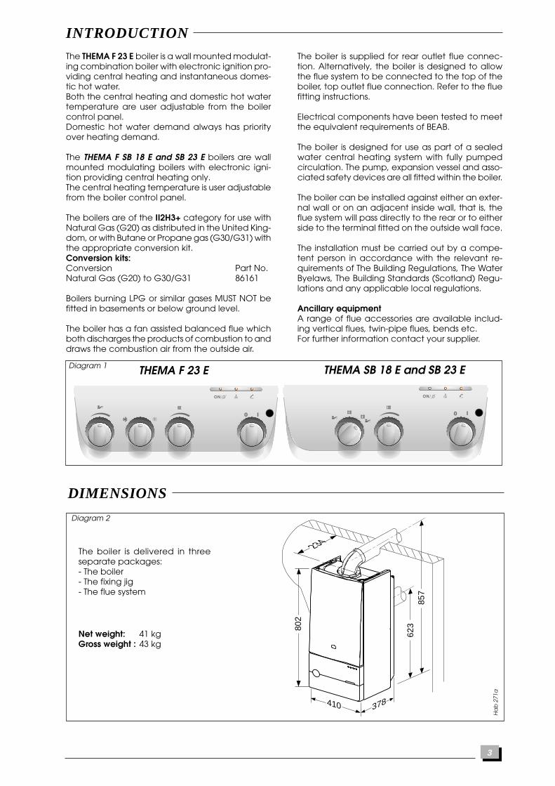
The THEMA F 23 E boiler is a wall mounted modulat-ing combination boiler with electronic ignition pro-viding central heating and instantaneous domes-tic hot water.Both the central heating and domestic hot watertemperature are user adjustable from the boilercontrol panel.Domestic hot water demand always has priorityover heating demand.
The THEMA F SB 18 E and SB 23 E boilers are wallmounted modulating boilers with electronic igni-tion providing central heating only.The central heating temperature is user adjustablefrom the boiler control panel.
The boilers are of the II2H3+ category for use withNatural Gas (G20) as distributed in the United King-dom, or with Butane or Propane gas (G30/G31) withthe appropriate conversion kit.Conversion kits:Conversion Part No.Natural Gas (G20) to G30/G31 86161
Boilers burning LPG or similar gases MUST NOT befitted in basements or below ground level.
The boiler has a fan assisted balanced flue whichboth discharges the products of combustion to anddraws the combustion air from the outside air.
The boiler is supplied for rear outlet flue connec-tion. Alternatively, the boiler is designed to allowthe flue system to be connected to the top of theboiler, top outlet flue connection. Refer to the fluefitting instructions.
Electrical components have been tested to meetthe equivalent requirements of BEAB.
The boiler is designed for use as part of a sealedwater central heating system with fully pumpedcirculation. The pump, expansion vessel and asso-ciated safety devices are all fitted within the boiler.
The boiler can be installed against either an exter-nal wall or on an adjacent inside wall, that is, theflue system will pass directly to the rear or to eitherside to the terminal fitted on the outside wall face.
The installation must be carried out by a compe-tent person in accordance with the relevant re-quirements of The Building Regulations, The WaterByelaws, The Building Standards (Scotland) Regu-lations and any applicable local regulations.
Ancillary equipmentA range of flue accessories are available includ-ing vertical flues, twin-pipe flues, bends etc.For further information contact your supplier.
Diagram 1 THEMA SB 18 E and SB 23 ETHEMA F 23 E
Diagram 2
DIMENSIONS
The boiler is delivered in threeseparate packages:- The boiler- The fixing jig- The flue system
Net weight: 41 kgGross weight : 43 kg
Ha
b 2
71a
378410
857
234
62380
2
4
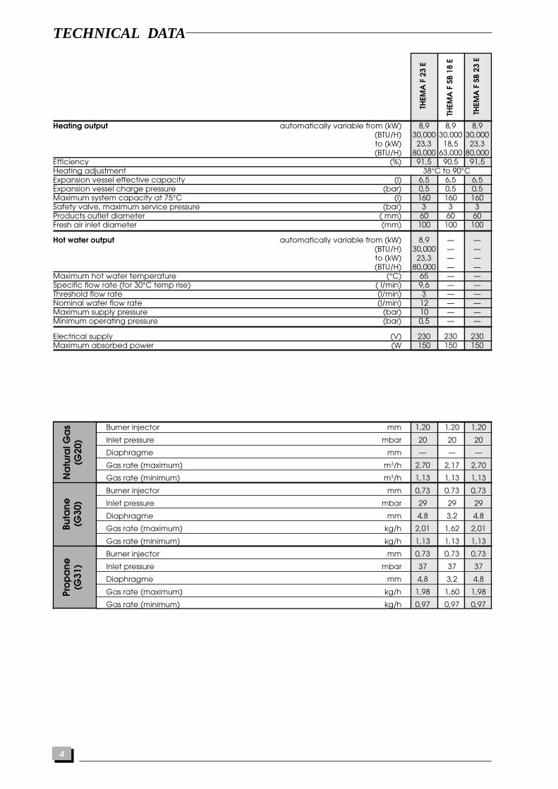
Burner injector mm 1,20 1,20 1,20
Inlet pressure mbar 20 20 20
Diaphragme mm — — —
Gas rate (maximum) m3/h 2,70 2,17 2,70
Gas rate (minimum) m3/h 1,13 1,13 1,13
Burner injector mm 0,73 0,73 0,73
Inlet pressure mbar 29 29 29
Diaphragme mm 4,8 3,2 4,8
Gas rate (maximum) kg/h 2,01 1,62 2,01
Gas rate (minimum) kg/h 1,13 1,13 1,13
Burner injector mm 0,73 0,73 0,73
Inlet pressure mbar 37 37 37
Diaphragme mm 4,8 3,2 4,8
Gas rate (maximum) kg/h 1,98 1,60 1,98
Gas rate (minimum) kg/h 0,97 0,97 0,97
Burner injector mm 2,4 2,4 2,4
Inlet pressure mbar 8 8 8
Diaphragme mm — — —
Gas rate (maximum) m3/h 3,88 3,88
Gas rate (minimum) m3/h 1,63 1,63 1,63
THEM
A F
23
E
TECHNICAL DATA
THEM
A F
SB
18 E
THEM
A F
SB
23 E
Heating output automatically variable from (kW) 8,9 8,9 8,9(BTU/H) 30,000 30,000 30,000to (kW) 23,3 18,5 23,3(BTU/H) 80,000 63,000 80,000
Efficiency (%) 91,5 90,5 91,5Heating adjustment 38°C to 90°CExpansion vessel effective capacity (l) 6,5 6,5 6,5Expansion vessel charge pressure (bar) 0,5 0,5 0,5Maximum system capacity at 75°C (l) 160 160 160Safety valve, maximum service pressure (bar) 3 3 3Products outlet diameter ( mm) 60 60 60Fresh air inlet diameter (mm) 100 100 100
Hot water output automatically variable from (kW) 8,9 — —(BTU/H) 30,000 — —to (kW) 23,3 — —(BTU/H) 80,000 — —
Maximum hot water temperature (°C) 65 — —Specific flow rate (for 30°C temp rise) ( l/min) 9,6 — —Threshold flow rate (l/min) 3 — —Nominal water flow rate (l/min) 12 — —Maximum supply pressure (bar) 10 — —Minimum operating pressure (bar) 0,5 — —
Electrical supply (V) 230 230 230Maximum absorbed power (W 150 150 150
Na
tura
l Ga
s(G
20)
Buta
ne(G
30)
Pro
pa
ne(G
31)
Tow
n g
as
(G13
0)
5
Ava
ilab
le p
ress
ure
(kP
a)
be
twe
en
hea
ting
flow
and
retu
rn
(10 kPa = 1 m WG)
1
2
3
4
5
50
40
30
20
10
0 500 1000
1
23
5
4
Flow rate through heating system (I/h)
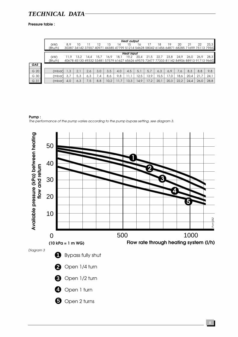
Pump :The performance of the pump varies according to the pump bypass setting, see diagram 3.
Diagram 3
TECHNICAL DATA
Heat output(kW) 8,9 10 11 12 13 14 15 16 17 18 19 20 21 22 23,3
(Btu/h) 30387 34142 37557 40971 44385 47799 51214 54628 58042 61456 64871 68285 71699 75113 79552
Heat input(kW) 11,9 13,2 14,4 15,7 16,9 18,1 19,2 20,4 21,5 22,7 23,8 24,9 26,0 26,9 28,3
(Btu/h) 40678 45130 49332 53481 57579 61627 65626 69575 73477 77333 81142 84906 88913 91713 96602GAS
G 20 (mbar) 1,3 2,1 2,6 3,0 3,5 4,0 4,5 5,1 5,7 6,3 6,9 7,6 8,3 8,8 9,8
G 30 (mbar) 3,7 5,3 6,3 7,4 8,6 9,8 11,1 12,5 13,9 15,5 17,0 18,6 20,4 21,7 24,1
G 31 (mbar) 4,0 6,3 7,5 8,8 10,2 11,7 13,3 14,9 17,2 20,1 20,3 22,2 24,4 26,0 28,8
Bypass fully shut
Open 1/4 turn
Open 1/2 turn
Open 1 turn
Open 2 turns
Po
m 0
52
Pressure table :

6
BOILER SCHEMATIC
Shy
131
A B C D E
4
5
14
3
17
19
8
9
10
11
13
12
16
20
21
6
24
2223
Diagram 4
3 - Ignition module4 - Heating temperature adjuster5 - Hot water temperature adjuster6 - Temperature/ressure gauge8 - Expansion vessel9 - Pump
10 - Automatic air vent11 - Burner12 - Heat exchanger bleed pipe13 - Heatexchanger14 - Gas valve16 - Heating and hot water thermistor17 - Ignition electrode19 - Overheat thermostat20 - Flame sense electrode21 - Loss of water pressure switch22 - Fan23 - Air pressure switch24 - Gas cock
A - Heating returnB - Cold water inletC - Heating flowD - Domestic hot water flowE - Gas supply
THEMA F 23 E
2223
A C E
4
16
17
19
6
8
9
10
11
13
12
21
3
14
24
3 - Ignition module4 - Heating temperature adjuster6 - Temperature/pressure gauge8 - Expansion vessel9 - Pump
10 - Automatic air vent11 - Burner12 - Heat exchanger bleed pipe13 - Heatexchanger14 - Gas valve16 - Heating and hot water thermistor17 - Ignition electrode19 - Overheat thermostat20 - Flame sense electrode21 - Loss of water pressure switch22 - Fan23 - Air pressure switch24 - Gas cock
A - Heating returnB - Cold water inletC - Heating flowD - Domestic hot water flowE - Gas supply
THEMA F SB 18 E - THEMA F SB 23 E
7
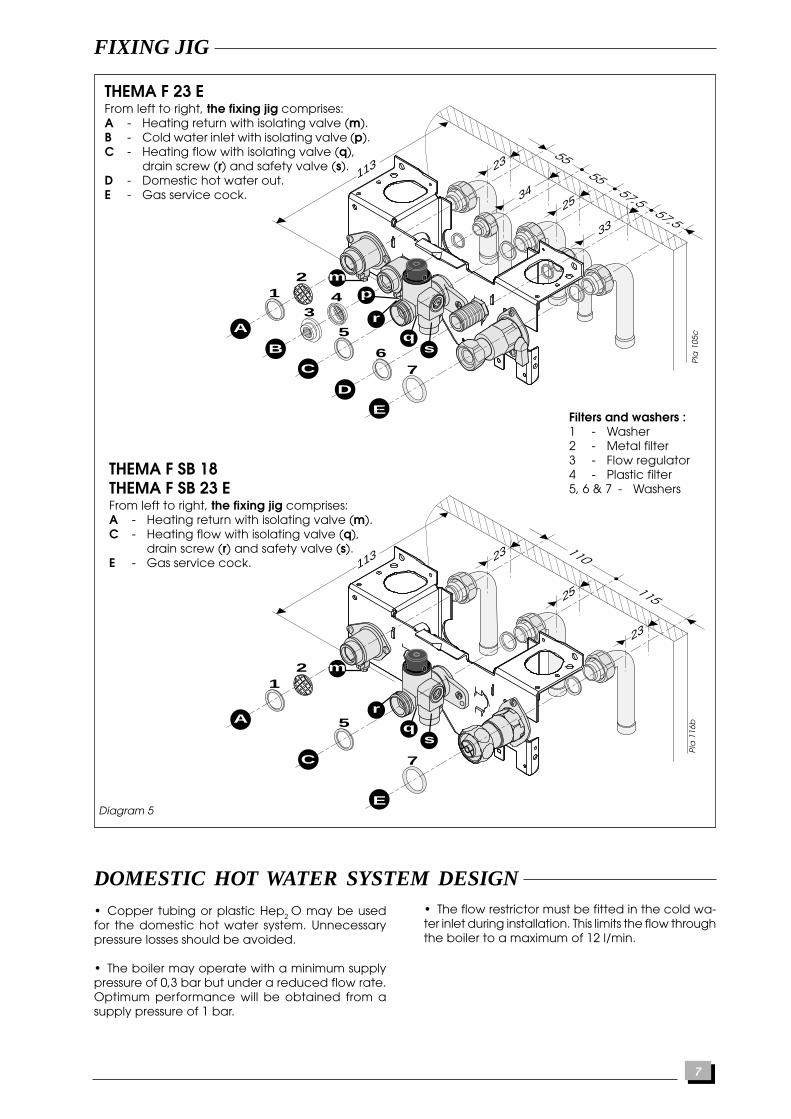
THEMA F 23 EFrom left to right, the fixing jig comprises:A - Heating return with isolating valve (m).B - Cold water inlet with isolating valve (p).C - Heating flow with isolating valve (q),
drain screw (r) and safety valve (s).D - Domestic hot water out.E - Gas service cock.
FIXING JIG
12
3
5
67
4
5555
57,557,5
r
p
q
3425
23113
s
33
A
B
C
D
E
m
Pla
105
c
Filters and washers :1 - Washer2 - Metal filter3 - Flow regulator4 - Plastic filter5, 6 & 7 - Washers
Diagram 5
THEMA F SB 18THEMA F SB 23 EFrom left to right, the fixing jig comprises:A - Heating return with isolating valve (m).C - Heating flow with isolating valve (q),
drain screw (r) and safety valve (s).E - Gas service cock.
12
5
7
r
p
q
25
23113
23
s
A
C
E
m
115
110
Pla
116
b
DOMESTIC HOT WATER SYSTEM DESIGN• Copper tubing or plastic Hep2 O may be usedfor the domestic hot water system. Unnecessarypressure losses should be avoided.
• The boiler may operate with a minimum supplypressure of 0,3 bar but under a reduced flow rate.Optimum performance will be obtained from asupply pressure of 1 bar.
• The flow restrictor must be fitted in the cold wa-ter inlet during installation. This limits the flow throughthe boiler to a maximum of 12 l/min.

8
HEATING SYSTEM DESIGN
Diagram 6
• The THEMA F boiler is compatible with any type ofinstallation.• Heating surfaces may consist of radiators, convec-tors or fan assisted convectors.• Pipe sectional areas shall be determined in accord-ance with normal practices, using the output/pres-sure curve (diagram 3). The distribution system shallbe calculated in accordance with the output require-ments of the actual system, not the maximum outputof the boiler. However, provision shall be made toensure sufficient flow so that the temperature differ-ence between the flow and return pipes be less thanor equal to 20°C. The minimum flow is 500 l/h.• The piping system shall be routed so as to avoidany air pockets and facilitate permanent venting ofthe installation. Bleed fittings shall be provided atevery high point of the system and on all radiators.• The total volume of water permitted for the heat-ing system depends, amongst other things, on thestatic head in the cold condition.The expansion vessel on the boiler is pressurised at 1bar (corresponding to a static head of 5 m w.g.) andallows a maximum system volume of 140 litres for anaverage temperature of 75°C and a maximum serv-ice pressure of 3 bar. This pressure setting can be modi-fied at commissioning stage if the static head differs.
An additional expansion vessel can be fitted to thesystem if required, see diagram 6.• Provision shall be made for a drain valve at thelowest point of the system.• Where thermostatic radiator valves are fitted, notall radiators must be fitted with this type of valve, andin particular, where the room thermostat is installed.• In the case of an existing installation, it is ESSENTIALthat the system is thoroughly flushed prior to installingthe new boiler using a proprietary product such asFernox or Sentinel. Contact the product manufac-turers for specific details.
Filling the systemProvision must be made for filling the system at lowlevel. The use of a WRC approved filling loop is stronglyrecommended, connected as shown in diagram 6.
Safety valve dischargeWARNING. It must not discharge above an en-trance or window or any type of public accessarea.Connect the safety valve discharge pipe to theboiler, the discharge must be extended using notless than 15 m o.d. pipe, to discharge in a visibleposition outside the building, facing downwardpreferably over a drain. The pipe must have a con-tinuous fall and be routed to a position so that anydischarge of water, possibly boiling or steam, can-not create any danger to persons, damage toproperty or external electrical components andwiring. Tighten all pipe connection joints.
Gas connection• The supply from the governed gas meter mustbe of adequate size to provide a constant inletworking pressure of 20 mbar (8 in w.g.).To avoid low gas pressure problems, it is recom-mended that the gas supply is connected using 22mm pipe.• On completion, the gas installation must betested using the pressure drop method and purgedin accordance with the current issue of BS6891.
Gas Safety (Installation and Use) RegulationsIn your interests and that of gas safety, it is the lawthat ALL gas appliances are installed and servicedby a competent person in accordance with theabove regulations.Flow
control valve Drain point
Filling point
Bypassvalve
Minimum 22 mm diameter
Tundish(supplied)
Pressurereducingvalve(supplied)
Domesticwater
Heatingcircuit
Return
Additionalexpansionvessel(if required)
Boiler
Hot
Col
d su
pply
Sch
173
• Heating system connections - Pipe diam 22 mm• Hot water system connections - Pipe diam 15 mm• Gas connection - Pipe diam 22 mm• Safety valve discharge - Pipe diam 15 mm
Water connectionConnect the water pipes to the fixing jig using thecopper tails supplied, see diagram 5.Warning: To prevent damage to the isolating cocks,do not solder joints or fittings with the copper tailsconnected.Connect the system pipework to the boiler observ-ing the correct flow and return format as shown indiagram 6.
PIPING SYSTEM INSTALLATION

9
234
50mini
29 60
255 mini
BOILER LOCATION
ClearancesThe position of the boiler must be such that there isadequate space for servicing.The recommended clearances are:40 mm either side of the boiler.600 mm at the front of the boiler.300 mm below the boiler.
Fixing jigThe fixing jig comprises three parts:1) The connecting plate which allows the connec-tion and soundness testing of all the pipework be-fore the boiler is fitted and helps support the weightof the boiler.2) The hook which supports the weight of the boiler.3) The template which ensures the hook and con-necting plate are correctly fitted relative to oneanother.
• Place template on wall in required position, mak-ing allowances for the necessary clearances etc.,see diagram 7.Note: It is permissible to install the boiler with re-duced clearances at the bottom and sides of theboiler PROVIDING that adequate consideration isgiven for Servicing/Repairs at a later date. If anydoubt exists, contact the Saunier Duval TechnicalHelpline 01773 828400.
• Mark the position of the holes for the hook andconnecting plate.• Drill, plug and fix the connecting plate and hookto the wall using suitable screws.• Check that both the hook and connecting plateare level.
If the boiler is not installed immediately, protect thevarious couplings to prevent any ingress of foreignmaterials e.g. plaster, paint etc.
Terminal positionThe minimum acceptable spacings from the ter-minal to obstructions and ventilation openings areshown in diagram 8.
Ins
012a
Diagram 7
The boiler must be installed so that the terminal isexposed to the external air.Note: Under certain weather conditions the fluemay produce a plume of condensation, this is quitenormal.If the terminal is fitted within 850mm of a plastic orpainted gutter or 450m of painted eaves, an alu-minium shield of a minimum length of 750mmshould be fitted to the underside of the gutter orpainted surface.
Should any doubt exist as to the permissible posi-tion of the terminal, contact the Saunier DuvalTechnical Helpline 01773 828400.
Cupboard or compartment ventilationThe boiler can be fitted in a cupboard or compart-ment without need for permanent ventilation.
Ve
n 0
60b
Diagram. 8
NC
D
M
AB
E F
G
I HL
A - Under a window ................................................. 300B - Under an air vent ................................................ 300C - Under a gutter ....................................................... 75D - Under a balcony ................................................. 300E - From an adjacent window ................................ 300F - From an adjacent air vent ................................. 300G - From vertical drain pipes or soil pipes .................. 75H - From an external corner of the building .......... 300I - From an internal corner of the building ........... 300L - From the ground or from another floor ............ 300M - Between two terminals vertically .................... 1500N - Between two terminals horizontally .................. 300
Minimum dimensions (in mm) for the positioning of flue terminals
10
BOILER INSTALLATION
Statutory requirementsThe installation of this boiler must be carried out bya competent person in accordance with the rel-evant requirements of the current issue of:
The Gas Safety (Installation and Use) RegulationsThe Building RegulationsThe local water company ByelawsThe Building Standards Regulations (Scotland)The Health and Safety at Work Act
Sheet metal partsWARNING. When installing or servicing this boiler,care should be taken when handling the edges ofsheet metal parts to avoid the possibility of personalinjury.
Ins
020
Ins
021
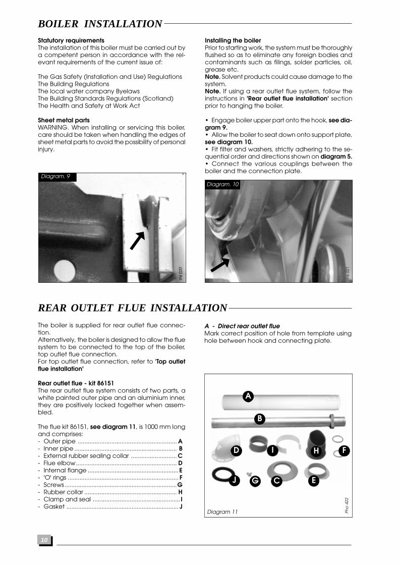
Installing the boilerPrior to starting work, the system must be thoroughlyflushed so as to eliminate any foreign bodies andcontaminants such as filings, solder particles, oil,grease etc.Note. Solvent products could cause damage to thesystem.Note. If using a rear outlet flue system, follow theinstructions in 'Rear outlet flue installation' sectionprior to hanging the boiler.
• Engage boiler upper part onto the hook, see dia-gram 9.• Allow the boiler to seat down onto support plate,see diagram 10.• Fit filter and washers, strictly adhering to the se-quential order and directions shown on diagram 5.• Connect the various couplings between theboiler and the connection plate.
Diagram. 9
Diagram. 10
REAR OUTLET FLUE INSTALLATION
The boiler is supplied for rear outlet flue connec-tion.Alternatively, the boiler is designed to allow the fluesystem to be connected to the top of the boiler,top outlet flue connection.For top outlet flue connection, refer to 'Top outletflue installation'
Rear outlet flue - kit 86151The rear outlet flue system consists of two parts, awhite painted outer pipe and an aluminium inner,they are positively locked together when assem-bled.
The flue kit 86151, see diagram 11, is 1000 mm longand comprises:- Outer pipe ........................................................... A- Inner pipe ............................................................. B- External rubber sealing collar ........................... C- Flue elbow............................................................ D- Internal flange ......................................................E- 'O' rings .................................................................. F- Screws ...................................................................G- Rubber collar ....................................................... H- Clamp and seal .................................................... I- Gasket ................................................................... J
A - Direct rear outlet flueMark correct position of hole from template usinghole between hook and connecting plate.
Ph
o 4
22
Diagram 11
A
B
CJ
HD F
EG
I
11
234
50mini
29 60
255 mini
REAR OUTLET FLUE INSTALLATION
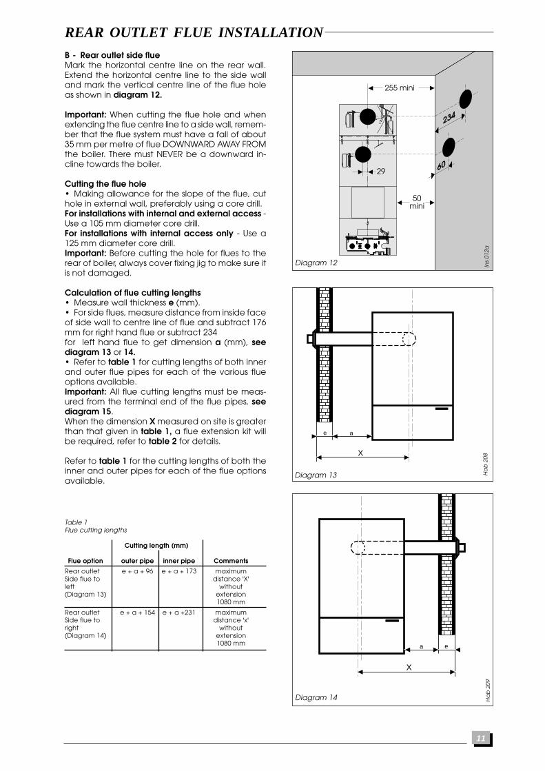
B - Rear outlet side flueMark the horizontal centre line on the rear wall.Extend the horizontal centre line to the side walland mark the vertical centre line of the flue holeas shown in diagram 12.
Important: When cutting the flue hole and whenextending the flue centre line to a side wall, remem-ber that the flue system must have a fall of about35 mm per metre of flue DOWNWARD AWAY FROMthe boiler. There must NEVER be a downward in-cline towards the boiler.
Cutting the flue hole• Making allowance for the slope of the flue, cuthole in external wall, preferably using a core drill.For installations with internal and external access -Use a 105 mm diameter core drill.For installations with internal access only - Use a125 mm diameter core drill.Important: Before cutting the hole for flues to therear of boiler, always cover fixing jig to make sure itis not damaged.
Calculation of flue cutting lengths• Measure wall thickness e (mm).• For side flues, measure distance from inside faceof side wall to centre line of flue and subtract 176mm for right hand flue or subtract 234for left hand flue to get dimension a (mm), seediagram 13 or 14.• Refer to table 1 for cutting lengths of both innerand outer flue pipes for each of the various flueoptions available.Important: All flue cutting lengths must be meas-ured from the terminal end of the flue pipes, seediagram 15.When the dimension X measured on site is greaterthan that given in table 1, a flue extension kit willbe required, refer to table 2 for details.
Refer to table 1 for the cutting lengths of both theinner and outer pipes for each of the flue optionsavailable.
Ha
b 2
09
Table 1Flue cutting lengths
Cutting length (mm)
Flue option outer pipe inner pipe Comments
Rear outlet e + a + 96 e + a + 173 maximumSide flue to distance 'X'left without(Diagram 13) extension
1080 mm
Rear outlet e + a + 154 e + a +231 maximumSide flue to distance 'x'right without(Diagram 14) extension
1080 mm
Diagram 12 Ins
012a
e a
X
Diagram 13 Ha
b 2
08
ea
X
Diagram 14

12
REAR OUTLET FLUE INSTALLATION
Extended flueThe horizontal flue is extended by using one or moreof the 1000 mm extension pipes, Saunier Duval partnumber 85091. These are connected together bypush fit type joints, clamps and seals.
Calculation of flue cutting lengths for extended flue• Using the correct number of extension kits as ta-ble 2, measure dimensions a and e, see diagram13 or 14. Cut both the inner and outer pipe to thedimensions given in table 3.
Important: All cutting lengths should be measuredfrom the push fit end of the extension pipe. Do notleave any burrs or sharp edges on the cut ends ofthe pipes.
Installation of flue assembly-direct rear flue• Fit rubber sealing collar (C) into groove at theouter end of pipe (A), see diagram 16.• Fit outer pipe (A) into wall with groove to theoutside.• Pull pipe inwards to bring rubber sealing collarhard up against external wall, see diagram16.• Fit internal plastic flange (F) onto outer pipe. Pushalong the pipe until engaged against internal wall.• From inside, insert inner pipe (B) into outer pipeturning anti-clockwise to allow inner to fully enterouter pipe.• Fit rubber sleeve (H) onto outer pipe.• Take hold of inner flue,twist clockwise and pushgently onto fan outlet.• Pull rubber sleeve onto boiler spigot ensuring agood seal.
Installation of flue assembly-side flue• Fit rubber sealing collar (C) into groove at theouter end of pipe (A), see diagram 16.• Fit outer pipe (A) into wall with groove to theoutside.• Pull pipe inwards to bring rubber sealing collarhard up against external wall, see diagram16.• Fit internal plastic flange (F) onto outer pipe. Pushalong the pipe until engaged against internal wall.• From inside, push inner pipe (B) into outer pipeturning anti-clockwise to allow inner to fully enterouter pipe.• Fit rubber sleeve (H) onto outer pipe.• Fit both 'O' rings (F) into flue elbow (D), one atthe inlet, one at the outlet. By necessity, they are aloose fit, apply a small amount of silicone greaseto each 'O' ring when fitting.
Important: If the flue has been cut, ensure that thereare no burrs that could damage the 'O' ring.
• Remove the backing from the self adhesive gas-ket (J) and carefully fit gasket to base of flue el-bow.• Fit elbow onto boiler and secure with the fourscrews (G).• Take hold of inner flue, twist clockwise and pushgently onto the elbow outlet taking care not to tearthe 'O' ring.• Pull rubber sleeve onto elbow ensuring a goodseal.
Table 2Number of extension kits required
Flue option Dimension 'X' No. ofextension kits
Side flue 1081 to 1811mm 1(left or right) 1812 to 2542 mm 2
Diagram 15 Ve
n 0
89
Cutting length
Outer pipe
Inner pipe
Cutting length
Table 3Extended flue cutting lengths
Cutting length (mm)
Flue option outer pipe inner pipe Comments
Rear outlet e + a - 906 e + a + 829 maximumSide flue to distance 'X'left without(Diagram 13) extension
1080 mm
Rear outlet e + a - 848 e + a + 771 maximumSide flue to distance 'x'right without(Diagram 14) extension
1080 mm
Ph
o 0
87
Diagram 16
13
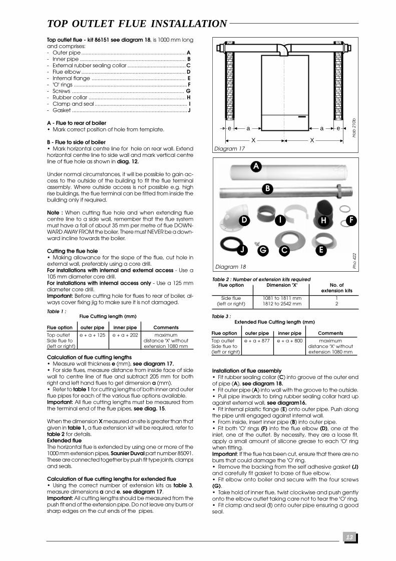
TOP OUTLET FLUE INSTALLATIONTop outlet flue - kit 86151 see diagram 18, is 1000 mm longand comprises:- Outer pipe ....................................................................... A- Inner pipe ........................................................................ B- External rubber sealing collar ........................................ C- Flue elbow ....................................................................... D- Internal flange ................................................................ E- 'O' rings ............................................................................. F- Screws ............................................................................ G- Rubber collar .................................................................. H- Clamp and seal ............................................................... I- Gasket .............................................................................. J
A - Flue to rear of boiler• Mark correct position of hole from template.
B - Flue to side of boiler• Mark horizontal centre line for hole on rear wall. Extendhorizontal centre line to side wall and mark vertical centreline of flue hole as shown in diag. 12.
Under normal circumstances, it will be possible to gain ac-cess to the outside of the building to fit the flue terminalassembly. Where outside access is not possible e.g. highrise buildings, the flue terminal can be fitted from inside thebuilding only if required.
Note : When cutting flue hole and when extending fluecentre line to a side wall, remember that the flue systemmust have a fall of about 35 mm per metre of flue DOWN-WARD AWAY FROM the boiler. There must NEVER be a down-ward incline towards the boiler.
Cutting the flue hole• Making allowance for the slope of the flue, cut hole inexternal wall, preferably using a core drill.For installations with internal and external access - Use a105 mm diameter core drill.For installations with internal access only - Use a 125 mmdiameter core drill.Important: Before cutting hole for flues to rear of boiler, al-ways cover fixing jig to make sure it is not damaged.
Ha
b 2
10b
Diagram 17
A
B
CJ
HD F
EG
I
Diagram 18 Ph
o 4
22
ee aa
XX
Table 2 : Number of extension kits requiredFlue option Dimension 'X' No. of
extension kits
Side flue 1081 to 1811 mm 1(left or right) 1812 to 2542 mm 2
Flue Cutting length (mm)
Flue option outer pipe inner pipe Comments
Top outlet e + a + 125 e + a + 202 maximumSide flue to distance 'X' without(left or right) extension 1080 mm
Calculation of flue cutting lengths• Measure wall thickness e (mm), see diagram 17.• For side flues, measure distance from inside face of sidewall to centre line of flue and subtract 205 mm for bothright and left hand flues to get dimension a (mm).• Refer to table 1 for cutting lengths of both inner and outerflue pipes for each of the various flue options available.Important: All flue cutting lengths must be measured fromthe terminal end of the flue pipes, see diag. 15.
When the dimension X measured on site is greater than thatgiven in table 1, a flue extension kit will be required, refer totable 2 for details.Extended flueThe horizontal flue is extended by using one or more of the1000 mm extension pipes, Saunier Duval part number 85091.These are connected together by push fit type joints, clampsand seals.
Calculation of flue cutting lengths for extended flue• Using the correct number of extension kits as table 3,measure dimensions a and e, see diagram 17.Important: All cutting lengths should be measured from thepush fit end of the extension pipe. Do not leave any burrs orsharp edges on the cut ends of the pipes.
Table 3 : Extended Flue Cutting length (mm)
Flue option outer pipe inner pipe Comments
Top outlet e + a + 877 e + a + 800 maximumSide flue to distance 'X' without(left or right) extension 1080 mm
Installation of flue assembly• Fit rubber sealing collar (C) into groove at the outer endof pipe (A), see diagram 18.• Fit outer pipe (A) into wall with the groove to the outside.• Pull pipe inwards to bring rubber sealing collar hard upagainst external wall, see diagram16.• Fit internal plastic flange (E) onto outer pipe. Push alongthe pipe until engaged against internal wall.• From inside, insert inner pipe (B) into outer pipe.• Fit both 'O' rings (F) into the flue elbow (D), one at theinlet, one at the outlet. By necessity, they are a loose fit,apply a small amount of silicone grease to each 'O' ringwhen fitting.Important: If the flue has been cut, ensure that there are noburrs that could damage the 'O' ring.• Remove the backing from the self adhesive gasket (J)and carefully fit gasket to base of flue elbow.• Fit elbow onto boiler and secure with the four screws(G).• Take hold of inner flue, twist clockwise and push gentlyonto the elbow outlet taking care not to tear the 'O' ring.• Fit clamp and seal (I) onto outer pipe ensuring a goodseal.
Table 1 :
14
ELECTRICAL CONNECTION
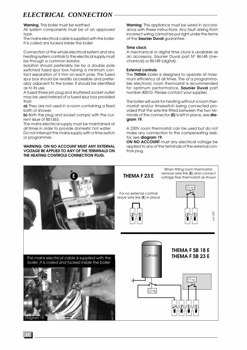
Warning. This boiler must be earthedAll system components must be of an approvedtype.The mains electrical cable is supplied with the boiler.It is coiled ans tucked inside the boiler
Connection of the whole electrical system and anyheating system controls to the electrical supply mustbe through a common isolator.Isolation should preferably be by a double poleswitched fused spur box having a minimum con-tact separation of 3 mm on each pole. The fusedspur box should be readily accessible and prefer-ably adjacent to the boiler. It should be identifiedas to its use.A fused three pin plug and shuttered socket outletmay be used instead of a fused spur box providedthat:a) They are not used in a room containing a fixedbath or shower.b) Both the plug and socket comply with the cur-rent issue of BS1363.The mains electrical supply must be maintained atall times in order to provide domestic hot water.Do not interrupt the mains supply with a time switchor programmer.
WARNING: ON NO ACCOUNT MUST ANY EXTERNALVOLTAGE BE APPLIED TO ANY OF THE TERMINALS ONTHE HEATING CONTROLS CONNECTION PLUG.
Warning: This appliance must be wired in accord-ance with these instructions. Any fault arising fromincorrect wiring cannot be put right under the termsof the Saunier Duval guarantee.
Time clockA mechanical or digital time clock is available asan accessory, Saunier Duval part N° 86148 (me-chanical) or 86149 (digital).
External controlsThe THEMA boiler is designed to operate at maxi-mum efficiency at all times. The of a programma-ble electronic room thermostat is recommendedfor optimum performance, Saunier Duval partnumber 40010. Please contact your supplier.
The boiler will work for heating without a room ther-mostat and/or timeswitch being connected pro-vided that the wire link fitted between the two ter-minals of the connector (E) is left in place, see dia-gram 19.
A 230V room thermostat can be used but do notmake any connection to the compensating resis-tor, see diagram 19.ON NO ACCOUNT must any electrical voltage beapplied to any of the terminals of the external con-trols plug.
sch
229
sch
228
E
°CFor no external controls
leave wire link (E) in place
When fitting room thermostat,remove wire link (E) and connectvoltage free thermostat as shown
Diagram 19 sch
227
°C
°C
The mains electrical cable is supplied with theboiler. It is coiled and tucked inside the boiler
THEMA F 23 E
THEMA F SB 18 ETHEMA F SB 23 ECylinder
15
COMMISSIONING
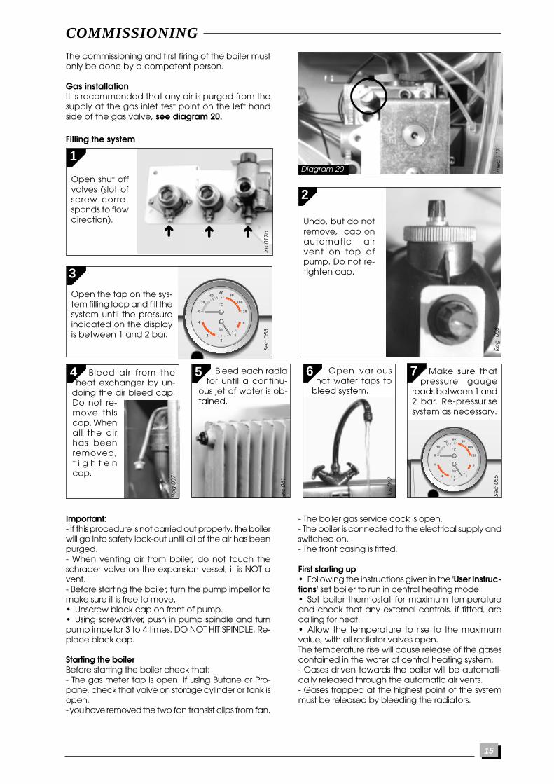
Important:- If this procedure is not carried out properly, the boilerwill go into safety lock-out until all of the air has beenpurged.- When venting air from boiler, do not touch theschrader valve on the expansion vessel, it is NOT avent.- Before starting the boiler, turn the pump impellor tomake sure it is free to move.• Unscrew black cap on front of pump.• Using screwdriver, push in pump spindle and turnpump impellor 3 to 4 times. DO NOT HIT SPINDLE. Re-place black cap.
Starting the boilerBefore starting the boiler check that:- The gas meter tap is open. If using Butane or Pro-pane, check that valve on storage cylinder or tank isopen.- you have removed the two fan transist clips from fan.
Ins
017a
The commissioning and first firing of the boiler mustonly be done by a competent person.
Gas installationIt is recommended that any air is purged from thesupply at the gas inlet test point on the left handside of the gas valve, see diagram 20.
- The boiler gas service cock is open.- The boiler is connected to the electrical supply andswitched on.- The front casing is fitted.
First starting up• Following the instructions given in the 'User Instruc-tions' set boiler to run in central heating mode.• Set boiler thermostat for maximum temperatureand check that any external controls, if fitted, arecalling for heat.• Allow the temperature to rise to the maximumvalue, with all radiator valves open.The temperature rise will cause release of the gasescontained in the water of central heating system.- Gases driven towards the boiler will be automati-cally released through the automatic air vents.- Gases trapped at the highest point of the systemmust be released by bleeding the radiators.
Diagram 20
Filling the system
1
Open shut offvalves (slot ofscrew corre-sponds to flowdirection).
Sec
055
7
Sec
055
Make sure thatpressure gauge
reads between 1 and2 bar. Re-pressurisesystem as necessary.
4 6 Open varioushot water taps to
bleed system.In
s 06
2
Ins
061
5 Bleed each radiator until a continu-
ous jet of water is ob-tained.
Re
g 0
07
B leed air from theheat exchanger by un-
doing the air bleed cap.Do not re-move thiscap. Whenall the airhas beenremoved,t i g h t e ncap.
2
3
Open the tap on the sys-tem filling loop and fill thesystem until the pressureindicated on the displayis between 1 and 2 bar.
Undo, but do notremove, cap onautomatic airvent on top ofpump. Do not re-tighten cap.
Re
g 0
08m
ec
117
16
De
s 04
4
COMMISSIONING
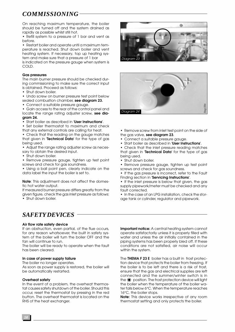
On reaching maximum temperature, the boilershould be turned off and the system drained asrapidly as possible whilst still hot.• Refill system to a pressure of 1 bar and vent asbefore.• Restart boiler and operate until a maximum tem-perature is reached. Shut down boiler and ventheating system. If necessary, top up heating sys-tem and make sure that a pressure of 1 baris indicated on the pressure gauge when system isCOLD.
Gas pressuresThe main burner pressure should be checked dur-ing commissioning to make sure the correct inputis obtained. Proceed as follows:• Shut down boiler.• Undo screw on burner pressure test point belowsealed combustion chamber, see diagram 23.• Connect a suitable pressure gauge.• Gain access to the rear of the control panel andlocate the range rating adjuster screw, see dia-gram 24.• Start boiler as described in 'User Instructions'.• Set boiler thermostat to maximum and checkthat any external controls are calling for heat.• Check that the reading on the gauge matchesthat given in 'Technical Data' for the type of gasbeing used.• Adjust the range rating adjuster screw as neces-sary to obtain the desired input.• Shut down boiler.• Remove pressure gauge, tighten up test pointscrews and check for gas soundness.• Using a ball point pen, clearly indicate on thedata label the input the boiler is set to.
Note: This adjustment does not affect the domes-tic hot water output.If measured burner pressure differs greatly from thegiven figure, check the gas inlet pressure as follows:• Shut down boiler.
Diagram 23
SAFETY DEVICESAir flow rate safety deviceIf an obstruction, even partial, of the flue occurs,for any reason whatsoever, the built in safety sys-tem of the boiler will turn the boiler OFF and thefan will continue to run.The boiler will be ready to operate when the faulthas been cleared.
In case of power supply failureThe boiler no longer operates.As soon as power supply is restored, the boiler willbe automatically restarted.
Overheat safetyIn the event of a problem, the overheat thermos-tat causes safety shutdown of the boiler. Should thisoccur, reset the thermostat by pressing in the redbutton. The overheat thermostat is located on theRHS of the heat exchanger.
Important notice: A central heating system cannotoperate satisfactorily unless it is properly filled withwater and unless the air initially contained in thepiping systems has been properly bled off. If theseconditions are not satisfied, air noise will occurwithin the system.
The THEMA F 23 E boiler has a built in frost protec-tion device that protects the boiler from freezing. Ifthe boiler is to be left and there is a risk of frost,ensure that the gas and electrical supplies are leftconnected and the summer/winter switch is inthe position. The frost protection device will lightthe boiler when the temperature of the boiler wa-ter falls below 6°C. When the temperature reaches16°C, the boiler stops.Note: This device works irrespective of any roomthermostat setting and only protects the boiler.
• Remove screw from inlet test point on the side ofthe gas valve, see diagram 23.• Connect a suitable pressure gauge.• Start boiler as described in 'User Instructions'.• Check that the inlet pressure reading matchesthat given in 'Technical Data' for the type of gasbeing used.• Shut down boiler.• Remove pressure gauge, tighten up test pointscrews and check for gas soundness.• If the gas pressure is incorrect, refer to the FaultFinding section in 'Servicing Instructions'.• If the inlet pressure is below that given, the gassupply pipework/meter must be checked and anyfault corrected.• In the case of an LPG installation, check the stor-age tank or cylinder, regulator and pipework.
Re
g 0
56
Diagram 24
17
SETTINGS
CHANGING GAS TYPE
Gas valve settingAll boilers are tested and factory set during manu-facture. Should it be necessary to reset a gas valve,for example after replacement, proceed as follows:• Shut down boiler.• Connect a suitable pressure gauge as describedin 'Commissioning'.
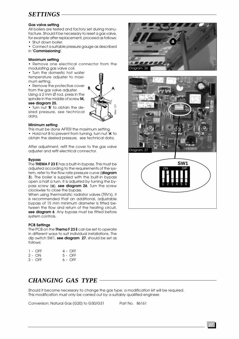
Maximum setting• Remove one electrical connector from themodulating gas valve coil.• Turn the domestic hot watertemperature adjuster to maxi-mum setting.• Remove the protective coverfrom the gas valve adjuster.Using a 2 mm Ø rod, press in thespindle in the middle of screw M,see diagram 25.• Turn nut 'B' to obtain the de-sired pressure, see technicaldata.
Minimum settingThis must be done AFTER the maximum setting.• Hold not B to prevent from turning, turn nut 'A' toobtain the desired pressure, see technical data.
After adjustment, refit the cover to the gas valveadjuster and refit electrical connector.
BypassThe THEMA F 23 E has a built-in bypass. This must beadjusted according to the requirements of the sys-tem, refer to the flow rate pressure curve (diagram3). The boiler is supplied with the built-in bypassopen a half a turn. It is adjusted by turning the by-pass screw (a), see diagram 26. Turn the screwclockwise to close the bypass.When using thermostatic radiator valves (TRV's), itis recommended that an additional, adjustablebypass of 15 mm minimum diameter is fitted be-tween the flow and return of the heating circuit,see diagram 6. Any bypass must be fitted beforesystem controls.
PCB SettingsThe PCB on the Thema F 23 E can be set to operatein different ways to suit individual installations. Thedip switch SW1, see diagram 27, should be set asfollows:
1 - OFF 4 - OFF2 - ON 5 - OFF3 - OFF 6 - OFF
Should it become necessary to change the gas type, a modification kit will be required.This modification must only be carried out by a suitably qualified engineer.
Conversion: Natural Gas (G20) to G30/G31 Part No. 86161
Re
g 0
13
a
Diagram. 26
Diagram. 27 Re
g 0
55
1 2 3 4 5 6
SW1ON DIP
Me
c 1
21
AB
18
To ensure the continued efficient and safe opera-tion of the boiler it is recommended that it ischecked and serviced at regular intervals. The fre-quency of servicing will depend upon the particu-lar installation conditions and usage, but in gen-eral once a year should be enough.
It is the law that any servicing is carried out by acompetent person.
Service Check and Preparation.• Operate boiler and check for any faults thatneed to be put right.• Isolate boiler from the gas and electrical supplies.• On completion check all gas carrying parts forsoundness with leak detection fluid.• The maximum domestic hot water flow rate is 12litres/minute.• Remove boiler casing as follows:
Upper front panel• Hinge down control cover to gain access to con-trol panel.• Disengage the two 'quarter turn' fasteners byturning the heads of the screws a quarter of a turntowards the centre of the boiler.• Carefully lower the panel down on its hinge untilit is horizontal.• Turn both plastic catches to release upper frontpanel.• Remove upper front panel by pulling forward atthe bottom and lifting off.Note: The upper front panel is retained by a plasticsafety strap, disengage this before removal.
Side panels• From below boiler, unscrew and remove blackplastic screws securing side panels to the boiler.• Prise out black plastic inserts and lift panel offboiler.
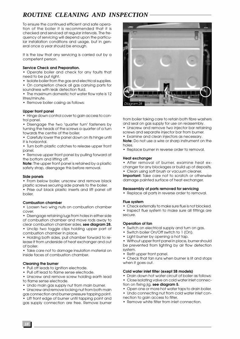
Combustion chamber• Loosen two wing nuts on combustion chambercover.• Disengage retaining lugs from holes in either sideof combustion chamber and move rods away toclear combustion chamber sides, see diagram 28.• Unclip two toggle clips holding upper part ofcombustion chamber in place.• Holding both sides, pull chamber forward to re-lease it from underside of heat exchanger and outof boiler.• Take care not to damage insulation material oninside faces of combustion chamber.
Cleaning the burner• Pull off leads to ignition electrode.• Pull off lead to flame sense electrode.• Unscrew and remove screw holding earth leadto flame sense electrode.• Undo main gas supply nut from main burner.• Unscrew and remove locking nut from both maingas connection and burner pressure tapping point.• Lift front edge of burner until tapping point andgas supply connection are free. Remove burner
De
s 04
7
ROUTINE CLEANING AND INSPECTION
Diagram 28
from boiler taking care to retain both fibre washersand seal on gas supply for use on reassembly.• Unscrew and remove two injector bar retainingscrews and separate injector bar from burner.• Examine and clean injectors as necessary.Note: Do not use a wire or sharp instrument on theholes.• Replace burner in reverse order to removal.
Heat exchanger• After removal of burner, examine heat ex-changer for any blockages or build up of deposits.• Clean using soft brush or vacuum cleaner.Important: Take care not to scratch or otherwisedamage painted surface of heat exchanger.
Reassembly of parts removed for servicing• Replace all parts in reverse order to removal.
Flue system• Check externally to make sure flue is not blocked.• Inspect flue system to make sure all fittings aresecure.
Operation of fan• Switch on electrical supply and turn on gas.• Switch boiler On/Off switch to 1 (On).• Light burner by opening a hot tap.• Without upper front panel in place, burner shouldbe prevented from lighting by air flow detectionsystem.• Refit upper front panel.• Check that fan runs when burner is lit and stopswhen it goes out.
Cold water inlet filter (exept SB models)• Drain down hot water circuit of boiler as follows:• Close isolating valve on cold water inlet connec-tion on fixing jig, see diagram 5.• Open one or more hot water taps to drain boiler.• Undo connecting nut from cold water inlet con-nection to gain access to filter.• Remove white filter from inlet connection.

19
REPLACEMENT OF PARTS
• Undo and remove screw securing spark genera-tor to bracket and remove spark generator.• Fit replacement spark generator in reverse orderto removal.• Reconnect two grey power supply leads and twoclear ignition leads to spark generator, the polarityis not important.• Refit lower terminal cover.
To replace main printed circuit board (PCB)• With lower front panel down as described previ-ously, undo and remove screw holding pump con-nection cover to PCB cover, see diagram 30.• Open cover and unclip plastic clip securingpump cable to lower front panel.• Pull off pump connector and earth lead.• Undo and remove four screws securing PCBcover to lower front panel.• Lift off PCB cover.• Pull off connectors CN6, CN7, CN8 and CN9 onPCB.• Undo and remove screw holding PCB to lowerfront panel.• Lifting PCB up slightly on LHS, pull PCB out of elec-trical connector on ignition PCB. Leave ignition PCBin place.
Note: Connecting pipework is telescopic, it may benecessary to slide sleeve back for easier access tofilter.• Clean and inspect filter, replace if necessary.• With both flow restrictor and filter in place, re-connect pipe to inlet connection and tighten.• Fully open isolating cock on cold water inlet con-nection and check for leaks.
Operation of water valve (exept SB models)• With the Summer/Winter control in the 'Summer'position, slowly open a convenient tap until boilerlights.• Measure water flow, it should not be greater than3,5 litres/minute.• If necessary, replace diaphragm.• Replace all outer panels.
ROUTINE CLEANING AND INSPECTION
To replace microswitch assembly exept SB models)• Disconnect microswitch by pulling off plug.• Unclip external controls connector from mount-ing bracket.• Undo two screws securing microswitch assemblyto reversing valve assembly, see diagram 29.• Remove microswitch assembly from reversingvalve.• Fit replacement microswitch assembly in reverseorder to removal.• Reconnect plug and refit external controls con-nection to bracket.
To replace fan• Disconnect power supply and earth leads to fan.• Unscrew and remove two fan retaining screwslocated at front edge of fan mounting plate.• Remove fan with mounting plate attached bypulling forwards and out of boiler.• Unscrew and remove three screws securing fanto fan mounting plate.• Fit replacement fan to mounting plate and se-cure with screws.• Fit replacement fan to boiler in reverse order toremoval making sure that mounting plate retain-ing lugs are properly engaged into flue hood.• Reconnect power supply and earth leads.Important: Make sure that fan outlet is correctly fit-ted into either the flue elbow for top outlet flue, orthe rear connector for rear outlet flue.Before commissioning boiler, remove the two plas-tic transit clips from replacement fan.
To replace air pressure switch• Locate air pressure switch in upper left hand cor-ner of sealed chamber.• Pull off plastic tube from left hand connection.• Grasp pressure switch and disengage it frombracket clips by pulling from the top.• Remove electrical connections from switch.• Fit electrical connections to terminals 1 and 3 ofreplacement switch.• Fit replacement switch in reverse order to re-moval.Important: Refit plastic tube to LEFT hand connec-tor (marked P1).
To replace spark generator• Locate spark generator on bracket to right handside of gas valve.• Undo and remove screw securing lower termi-nal cover to bracket and remove bracket.• Disconnect four leads from spark generator.
Diagram 30
Sch
228
Ha
b 2
86
Diagram 29
microswitch on THEMA F 23 E
20
• Fit replacement PCB in reverse order to removal.Important: When fitting replacement PCB, ensurethat control knob spindles correctly locate into PCBadjuster slots.• Refit connectors and covers in reverse order toremoval.
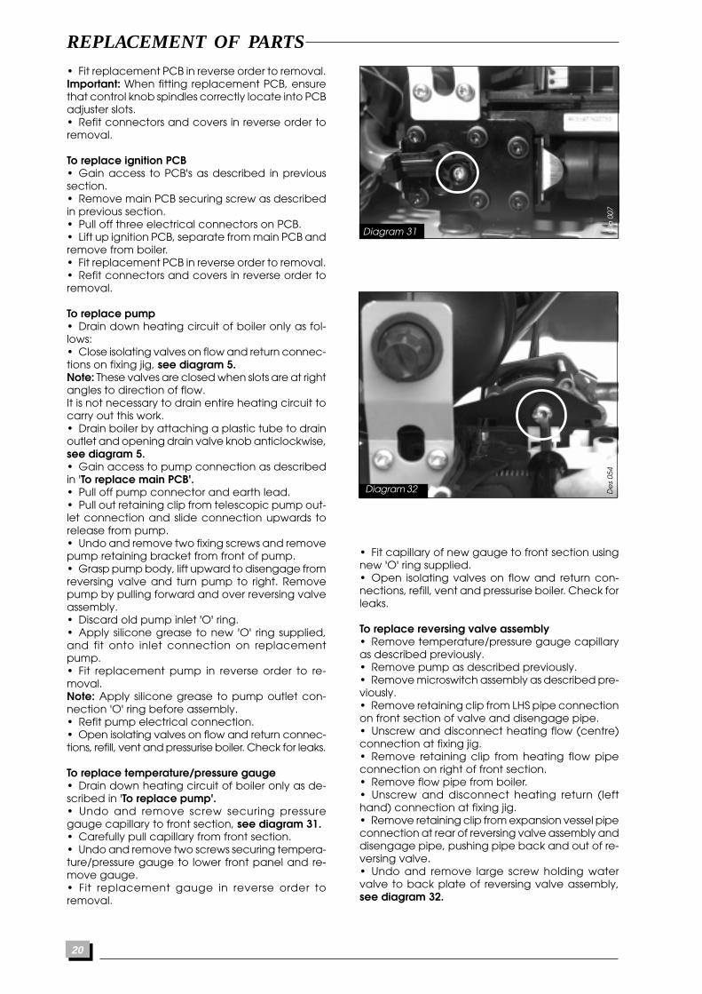
To replace ignition PCB• Gain access to PCB's as described in previoussection.• Remove main PCB securing screw as describedin previous section.• Pull off three electrical connectors on PCB.• Lift up ignition PCB, separate from main PCB andremove from boiler.• Fit replacement PCB in reverse order to removal.• Refit connectors and covers in reverse order toremoval.
To replace pump• Drain down heating circuit of boiler only as fol-lows:• Close isolating valves on flow and return connec-tions on fixing jig, see diagram 5.Note: These valves are closed when slots are at rightangles to direction of flow.It is not necessary to drain entire heating circuit tocarry out this work.• Drain boiler by attaching a plastic tube to drainoutlet and opening drain valve knob anticlockwise,see diagram 5.• Gain access to pump connection as describedin 'To replace main PCB'.• Pull off pump connector and earth lead.• Pull out retaining clip from telescopic pump out-let connection and slide connection upwards torelease from pump.• Undo and remove two fixing screws and removepump retaining bracket from front of pump.• Grasp pump body, lift upward to disengage fromreversing valve and turn pump to right. Removepump by pulling forward and over reversing valveassembly.• Discard old pump inlet 'O' ring.• Apply silicone grease to new 'O' ring supplied,and fit onto inlet connection on replacementpump.• Fit replacement pump in reverse order to re-moval.Note: Apply silicone grease to pump outlet con-nection 'O' ring before assembly.• Refit pump electrical connection.• Open isolating valves on flow and return connec-tions, refill, vent and pressurise boiler. Check for leaks.
To replace temperature/pressure gauge• Drain down heating circuit of boiler only as de-scribed in 'To replace pump'.• Undo and remove screw securing pressuregauge capillary to front section, see diagram 31.• Carefully pull capillary from front section.• Undo and remove two screws securing tempera-ture/pressure gauge to lower front panel and re-move gauge.• Fit replacement gauge in reverse order toremoval.
REPLACEMENT OF PARTS
• Fit capillary of new gauge to front section usingnew 'O' ring supplied.• Open isolating valves on flow and return con-nections, refill, vent and pressurise boiler. Check forleaks.
To replace reversing valve assembly• Remove temperature/pressure gauge capillaryas described previously.• Remove pump as described previously.• Remove microswitch assembly as described pre-viously.• Remove retaining clip from LHS pipe connectionon front section of valve and disengage pipe.• Unscrew and disconnect heating flow (centre)connection at fixing jig.• Remove retaining clip from heating flow pipeconnection on right of front section.• Remove flow pipe from boiler.• Unscrew and disconnect heating return (lefthand) connection at fixing jig.• Remove retaining clip from expansion vessel pipeconnection at rear of reversing valve assembly anddisengage pipe, pushing pipe back and out of re-versing valve.• Undo and remove large screw holding watervalve to back plate of reversing valve assembly,see diagram 32.
Diagram 31 Cla
007
De
s 05
4
Diagram 32

21
REPLACEMENT OF PARTS
• Push water valve back to disengage it from re-versing valve.• Unclip and remove loss of water pressure switchfrom left of reversing valve assembly, see diagram33.• From below boiler, undo and remove threescrews holding reversing valve to bottom plate ofboiler. Remove complete reversing valve assem-bly from boiler.• Undo and remove heating return connectingpipe and hose from rear of reversing valve assem-bly. Fit hose to replacement reversing valve assem-bly.• Fit replacement reversing valve into boiler in re-verse order to removal.Note: Use new 'O' rings, retaining clip, filter andwasher provided.• Unscrew and remove microswitch assembly fromtop of replacement reversing valve assembly toallow refitting of water valve.Note: fit expansion vessel pipe and loss of waterswitch to reversing valve assembly before pump,to ensure that it is correctly located. Apply siliconegrease to all 'O' rings and hoses prior to assembly.• Open isolating valves on flow and return con-nections, refill, vent and pressurise boiler. Check forleaks.
To replace reversing valve front section• Remove pressure gauge capillary as describedpreviously.• Remove pipe connections from either side ofreversing valve front section, refer to previous sec-tion.• Move short selector lever on front of valve to lefthand position.• From below boiler, undo and remove single screwholding reversing valve front plate to bottom plateof boiler.• Undo and remove six screws holding front sec-tion to rear section of reversing valve, see diagram34.• Remove front plate complete with pump bracketand then front section from reversing valve, alongwith rubber sealing gasket.• Assemble bypass valve provided and fit into holein underside of replacement front section. Fit 'U'shaped retaining clip.Note: Use bypass valve fitted to original front sec-tion for guidance.• Fit replacement front section, with gasket, to rearsection.• Locate front plate and replace six fixing screws.Take care to evenly tighten screws ensuring theyare not cross threaded.• Refit pipe connections to either side of front sec-tion using new 'O' rings provided. Apply siliconegrease to 'O' rings before fitting.• Refit pressure gauge capillary in reverse order toremoval.• Ensure short selector lever on front of valve is setto right hand position.• Open isolating valves on flow and return con-nections, refill, vent and pressurise boiler. Check forleaks.
To replace loss of water switch• Drain down heating circuit of boiler only as de-scribed in 'To replace pump'.Note: It is not necessary to drain entire heating cir-cuit to carry out this work.• Pinch plastic cover to release retaing clips andremove cover from switch. Pull plug lead fromswitch terminals.• Remove clip holding switch into left side of re-versing valve assembly.• Pull switch out of reversing valve assembly, seediagram 33.• Fit replacement switch in reverse order to re-moval, using new 'O' ring provided and applyingsilicone grease to 'O' ring before fitting.• Reconnect plug to switch terminals.• Open isolating valves on flow and return con-nections, refill, vent and pressurise boiler. Check forleaks.
To replace water valve or diaphragm (except SBmodels)• Drain down hot water circuit of boiler only asdescribed in 'Routine Cleaning and Inspection'.• Remove microswitch assembly as described pre-viously.• Unscrew connecting nut from cold water inletconnection, second from left on fixing jig. Keep fil-ter and flow regulator.• Remove clip holding connecting pipe in rear ofwater valve. From below boiler, grip clip with longnosed pliers and pull down.Note: This connecting pipe is telescopic, it may benecessary to slide back brass sleeve to facilitateremoval.
Diagram 33 Sec
059
Diagram 34 Cla
007
22
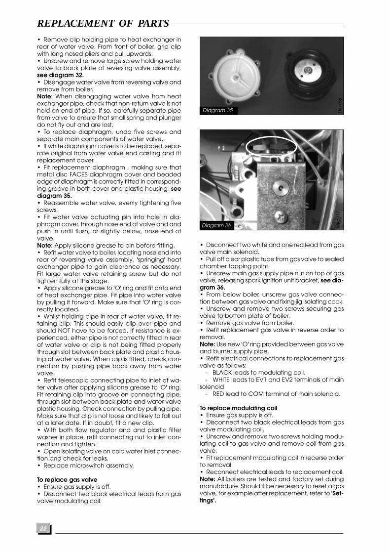
• Remove clip holding pipe to heat exchanger inrear of water valve. From front of boiler, grip clipwith long nosed pliers and pull upwards.• Unscrew and remove large screw holding watervalve to back plate of reversing valve assembly,see diagram 32.• Disengage water valve from reversing valve andremove from boiler.Note: When disengaging water valve from heatexchanger pipe, check that non-return valve is notheld on end of pipe. If so, carefully separate pipefrom valve to ensure that small spring and plungerdo not fly out and are lost.• To replace diaphragm, undo five screws andseparate main components of water valve.• If white diaphragm cover is to be replaced, sepa-rate original from water valve end casting and fitreplacement cover.• Fit replacement diaphragm , making sure thatmetal disc FACES diaphragm cover and beadededge of diaphragm is correctly fitted in correspond-ing groove in both cover and plastic housing, seediagram 35.• Reassemble water valve, evenly tightening fivescrews.• Fit water valve actuating pin into hole in dia-phragm cover, through nose end of valve and andpush in until flush, or slightly below, nose end ofvalve.Note: Apply silicone grease to pin before fitting.• Refit water valve to boiler, locating nose end intorear of reversing valve assembly, 'springing' heatexchanger pipe to gain clearance as necessary.Fit large water valve retaining screw but do nottighten fully at this stage.• Apply silicone grease to 'O' ring and fit onto endof heat exchanger pipe. Fit pipe into water valveby pulling it forward. Make sure that 'O' ring is cor-rectly located.• Whilst holding pipe in rear of water valve, fit re-taining clip. This should easily clip over pipe andshould NOT have to be forced. If resistance is ex-perienced, either pipe is not correctly fitted in rearof water valve or clip is not being fitted properlythrough slot between back plate and plastic hous-ing of water valve. When clip is fitted, check con-nection by pushing pipe back away from watervalve.• Refit telescopic connecting pipe to inlet of wa-ter valve after applying silicone grease to 'O' ring.Fit retaining clip into groove on connecting pipe,through slot between back plate and water valveplastic housing. Check connection by pulling pipe.Make sure that clip is not loose and likely to fall outat a later date. If in doubt, fit a new clip.• With both flow regulator and and plastic filterwasher in place, refit connecting nut to inlet con-nection and tighten.• Open isolating valve on cold water inlet connec-tion and check for leaks.• Replace microswitch assembly.
To replace gas valve• Ensure gas supply is off.• Disconnect two black electrical leads from gasvalve modulating coil.
REPLACEMENT OF PARTS
De
s 05
8
• Disconnect two white and one red lead from gasvalve main solenoid.• Pull off clear plastic tube from gas valve to sealedchamber tapping point.• Unscrew main gas supply pipe nut on top of gasvalve, releasing spark ignition unit bracket, see dia-gram 36.• From below boiler, unscrew gas valve connec-tion between gas valve and fixing jig isolating cock.• Unscrew and remove two screws securing gasvalve to bottom plate of boiler.• Remove gas valve from boiler.• Refit replacement gas valve in reverse order toremoval.Note: Use new 'O' ring provided between gas valveand burner supply pipe.• Refit electrical connections to replacement gasvalve as follows:
- BLACK leads to modulating coil.- WHITE leads to EV1 and EV2 terminals of main
solenoid- RED lead to COM terminal of main solenoid.
To replace modulating coil• Ensure gas supply is off.• Disconnect two black electrical leads from gasvalve modulating coil.• Unscrew and remove two screws holding modu-lating coil to gas valve and remove coil from gasvalve.• Fit replacement modulating coil in recerse orderto removal.• Reconnect electrical leads to replacement coil.Note: All boilers are tested and factory set duringmanufacture. Should it be necessary to reset a gasvalve, for example after replacement, refer to 'Set-tings'.
Diagram 35
Diagram 36 Me
c 1
17
23
REPLACEMENT OF PARTS
To replace safety valve• Drain down entire heating system.• From below boiler, disconnect heating flow pipefrom rear of fixing jig.• Undo heating flow connection on front of fixingjig. Remove clip from heating flow pipe connec-tion on right of front section of reversing valve. Pullpipe towards right and out of reversing valve. Re-move pipe from boiler and keep.• From below boiler, disconnect safety valve dis-charge pipe.• Working through boiler from the front using a longscrewdriver, undo and remove screw holding safetyvalve assembly to fixing jig.• Remove complete safety valve assembly fromfixing jig and remove from boiler.• Fit replacement safety valve in reverse order toremoval.Note: Apply silicone grease to 'O' ring before fixingpipe into right hand side of reversing valve.• Refill heating system and boiler, vent and pres-surise as described previously.
To replace heat exchanger• Drain down both heating and hot water circuitsof boiler only as described previously.Note: It is not necessary to drain entire heating sys-tem to carry out this work.• Remove combustion chamber cover as de-scribed in 'Routine Cleaning and Inspection'.• Remove two clips from heating connections toleft side of heat exchanger.• Remove clip holding pump outlet connectioninto pump and slide connection up pump outletpipe. Pull complete pipe down to disengage fromheat exchanger.• Remove retaining clip from LHS pipe connectionon front section of valve and disengage pipe.• Disengage pipe downwards from heat ex-changer.• Unscrew and disconnect two hot water connec-tions to right side of heat exchanger.• Grasp both sides of heat exchanger and slideforwards and out of boiler.• Fit replacement heat exchanger in reverse or-der to removal.Note: Use new sealing washers and 'O' rings pro-vided.• Open isolating valves on flow and return con-nections, refill, vent and pressurise boiler. Check forleaks.
To replace expansion vessel1 Boiler in placeNote: The expansion vessel can be replaced withthe boiler in place provided that there is a mini-mum clearance of 400mm on one side of the boilerand that no vertical pipework passes betweenboiler and wall on that side.• Drain down the heating circuit of the boiler onlyas described in 'To replace pump'.Note: It is not necessary to drain entire heating sys-tem to carry out this work.• Remove pump from boiler as described previ-ously.
• Unscrew pipe connection nut from expansionvessel and disengage pipe from connection. Keepsealing washer.• Whilst supporting weight of vessel, push bottomof vessel away from boiler, disengaging threadedconnection from hole in rear of boiler. Allow vesselto drop out of its two upper retaining brackets.• Remove vessel to side of boiler.• Fit replacement expansion vessel in reverse or-der to removal ensuring that sealing washer is fit-ted to vessel pipe connection.• Check that vessel charge pressure is 1bar. Cor-rect if necessary.• Open isolating valves on flow and return con-nections, refill, vent and pressurise boiler. Check forleaks.
2 Boiler removed from wall• Drain down the heating circuit of the boiler onlyas described in 'To replace pump'.Note: It is not necessary to drain entire heating sys-tem to carry out this work.• Ensure that gas and electrical supplies to boilerare turned off.• Disconnect flue from either rear or top of boileras applicable.• Disconnect external controls connections, if ap-plicable.• Unscrew and disconnect five connections be-tween fixing jig and boiler.• Disengage pipe connections. Lift boiler off hang-ing bracket and place on a convenient workingsurface.• Remove expansion vessel from boiler as de-scribed in previous section.• Fit replacement vessel in reverse order to removaland check charge pressure.• Replace boiler on wall, tighten all connections,gas connection first, ensuring that all sealing wash-ers, filters and the cold water flow regulator are fit-ted before tightening.• Reconnect flue system.• Open isolating valves on flow and return con-nections, refill, vent and pressurise boiler. Check forleaks.• Reconnect external controls connections, if ap-plicable.• Reconnect gas and electrical supplies to boiler.• Check for gas soundness.
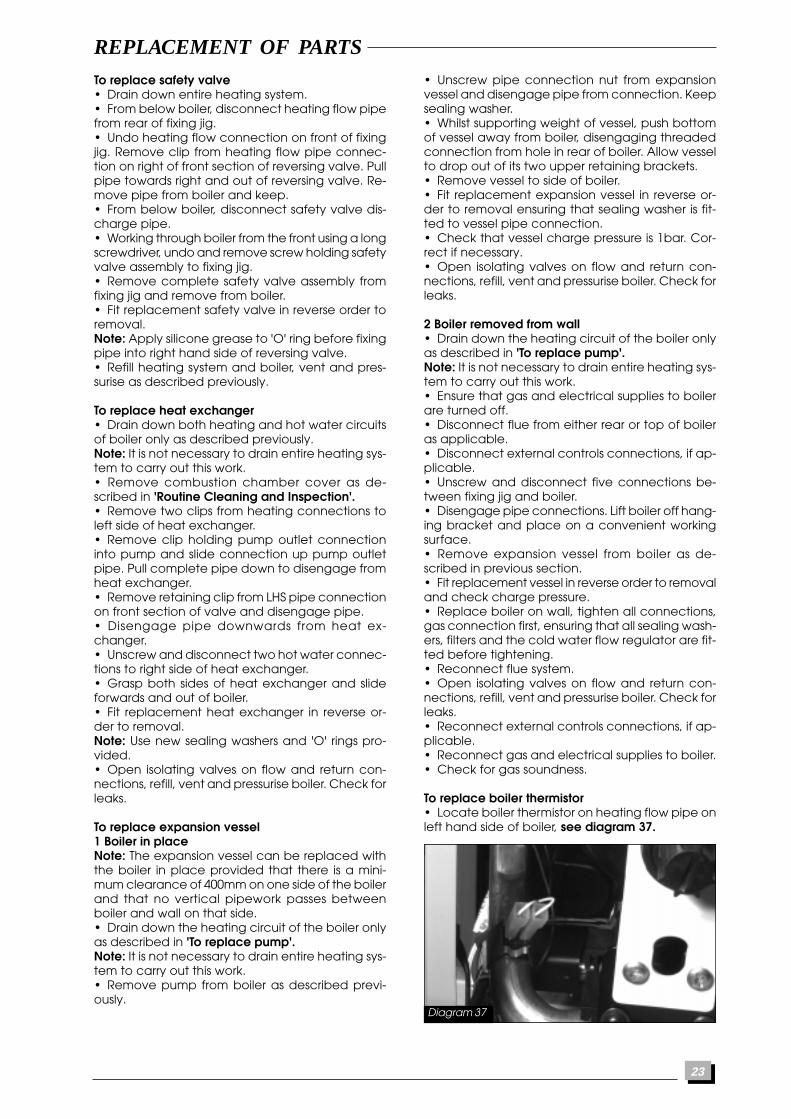
To replace boiler thermistor• Locate boiler thermistor on heating flow pipe onleft hand side of boiler, see diagram 37.
Diagram 37

24
REPLACEMENT OF PARTS
• Unclip thermistor from pipe.• Pull off electrical cennections from thermistor.• Fit replacement thermistor in reverse order to re-moval.Note: No heat sink compound is required. The po-larity of the connections is not important.
To replace overheat thermostat• Locate the overheat thermostat on the righthand side of the heat exchanger.• Pull off the electrical connections from the ther-mostat.• Unscrew and remove two screws holding ther-mostat to heat exchanger.• Fit replacement thermostat in reverse order toremoval, using heat sink compound on the con-tact surface of thermostat.• Refit electrical leads, the polarity is not impor-tant.
To replace combustion chamber insulationFront section• Remove combustion chamber from boiler asdescribed in 'Routine Cleaning and Inspection'.• Slide side panels out of combustion chambersides.• Lift front insulation panel free from retaining lugsand away from cover.• Fit replacement panels in reverse order to re-moval.
Rear panel• Remove burner from boiler as described in 'Rou-tine Cleaning and Inspection'.• Remove clip from base of insulation panel.• Pull bottom edge of insulation panel forward,downward and out from behind heat exchanger.• Fit replacement panel in reverse order to re-moval.• Replace burner into boiler in reverse order to re-moval.
To replace ignition electrode• Remove combustion chamber from boiler asdescribed in 'Routine Cleaning and Inspection'.• Pull off ignition leads from ignition electrode.• Unscrew and remove two screws holding igni-tion electrode onto burner.• Fit replacement ignition electrode in reverse or-der to removal.• Refit ignition leads, the polarity is not important.
To replace flame sense electrode• Remove combustion chamber from boiler asdescribed in 'Routine Cleaning and Inspection'.• Pull off lead from flame sense electrode.• Unscrew and remove screw holding earth leadto flame sense electrode.• Unscrew and remove screw holding flame senseelectrode onto burner.• Fit replacement flame sense electrode in reverseorder to removal.• Refit lead.
To replace burner• Pull off ignition and flame sense leads from elec-trodes.• Remove burner from boiler as described in 'Rou-tine Cleaning and Inspection'.• Remove ignition and flame sense electrodes asdescribed in previous sections.• Unscrew and remove two screws holding burnerinjector bar to burner and remove injector bar.• Asemble replacement burner, supplied in parts,as follows:• Fit burner injectors to injector bar and tighten.• Assemble burner elements (14) into front and rearburner supports with securing pins and rods, usingoriginal burner for guidance.• Fit burner injector bar to burner.• Fit ignition and flame sense electrodes to burner.• Fit replacement burner to boiler in reverse orderto removal.• Reconnect ignition and flame sense leads toelectrodes. Reconnect earth lead to flame senseelectrode. The polarity of the ignition leads is notimportant.
To replace burner injectors• Remove burner as described previously.• Remove ignition and flame sense electrodes asdescribed in previous sections.• Unscrew and remove two screws holding burnerinjector bar to burner and remove injector bar.• Unscrew and remove burner injectors from burnerbar.• Fit replacement injectors to injector bar andtighten.Note: make sure that injector size, marked on eachinjector, is the same as that given in 'Technical Data'.• Reassemble burner and replace into boiler inreverse order to removal.
To replace timeclock• Gain access to rear of lower control panel asdescribed in 'Routine Cleaning and Inspection'.• Unscrew and remove two screws holdingtimeclock to lower control panel.• Remove PCB cover.• Remove timeclock plug from connection CN7on main PCB.• Fit replacement timeclock in reverse order to re-moval.
25
SCHEMATIC WIRING DIAGRAM
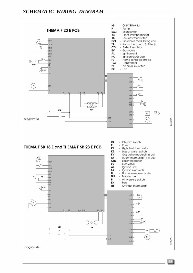
Sch
242
IG - ON/OFF switchP - PumpSW3 - MicroswitchK4 - Hight limit thermostatK5 - Loss of water switchEV1 - Gas valve modulating coilTA - Room thermostat (if fitted)CTN - Boiler thermistorEV - Gas valveAL - Ignition unitFA - Ignition electrodeFL - Flame sense electrodeTRA - TransformerPr - Air pressure switchEX - Fan
Diagram 38
N
L
P
Ex
EV1
EV
TRA
6.14
6.13
6.15
6.11
CTN
SW3
TA
K5
K4
Pr
FL
Ra
FAAl
6.12
6.9
13.2
13.3
13.1
13.4
14.114.214.7
14.3
14.4
14.5
14.6
14.8
14.9
6.8
6.66.46.2
6.3
2.2
2.1
9.1 9.2 8.4 8.3 8.2 8.1
12.1
12.2
PTHEMA F 23 E PCB
N
L
P
Ex
EV1
EV
TRA
6.14
6.15
6.11
CTN
TH
V3V
TA
K5
K4
Pr
FL
Ra
FAAl
6.12
6.9
13.2
13.3
13.1
13.4
14.114.214.7
14.3
14.4
14.5
14.6
14.8
14.9
6.8
6.66.46.2
6.3
3.33.2
3.1
2.2
2.1
9.1 9.2 8.4 8.3 8.2 8.1
12.1
12.2
Diagram 39
Sch
240
IG - ON/OFF switchP - PumpK4 - Hight limit thermostatK5 - Loss of water switchEV1 - Gas valve modulating coilTA - Room thermostat (if fitted)CTN - Boiler thermistorEV - Gas valveAL - Ignition unitFA - Ignition electrodeFL - Flame sense electrodeTRA - TransformerPr - Air pressure switchEX - FanTH - Cylinder thermostat
THEMA F SB 18 E and THEMA F SB 23 E PCB
IG
IG
26
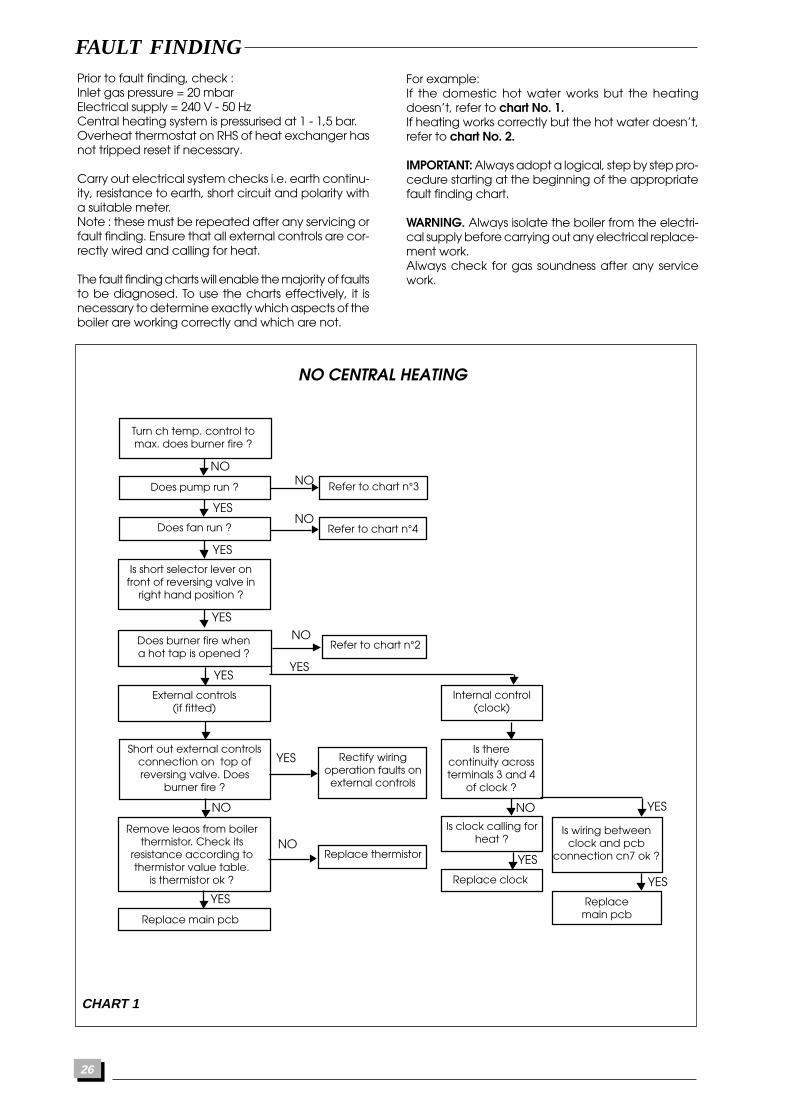
FAULT FINDINGPrior to fault finding, check :Inlet gas pressure = 20 mbarElectrical supply = 240 V - 50 HzCentral heating system is pressurised at 1 - 1,5 bar.Overheat thermostat on RHS of heat exchanger hasnot tripped reset if necessary.
Carry out electrical system checks i.e. earth continu-ity, resistance to earth, short circuit and polarity witha suitable meter.Note : these must be repeated after any servicing orfault finding. Ensure that all external controls are cor-rectly wired and calling for heat.
The fault finding charts will enable the majority of faultsto be diagnosed. To use the charts effectively, it isnecessary to determine exactly which aspects of theboiler are working correctly and which are not.
For example:If the domestic hot water works but the heatingdoesn’t, refer to chart No. 1.If heating works correctly but the hot water doesn’t,refer to chart No. 2.
IMPORTANT: Always adopt a logical, step by step pro-cedure starting at the beginning of the appropriatefault finding chart.
WARNING. Always isolate the boiler from the electri-cal supply before carrying out any electrical replace-ment work.Always check for gas soundness after any servicework.
NO CENTRAL HEATING
CHART 1
Replace main pcb
Replace clock
Refer to chart n°3
Refer to chart n°4Does fan run ?
Does pump run ?
Internal control(clock)
External controls(if fitted)
Remove leaos from boilerthermistor. Check its
resistance according tothermistor value table.
is thermistor ok ?
Short out external controlsconnection on top ofreversing valve. Does
burner fire ?
Rectify wiringoperation faults on
external controls
Is wiring betweenclock and pcb
connection cn7 ok ?Replace thermistor
Is clock calling forheat ?
Is therecontinuity acrossterminals 3 and 4
of clock ?
Replacemain pcb
Turn ch temp. control tomax. does burner fire ?
NO
NO
NO
NO
NONO
YES
NO
YES
YES
YES
YES
YES
YES
Is short selector lever onfront of reversing valve in
right hand position ?
Does burner fire whena hot tap is opened ?
Refer to chart n°2
YES
YES
YES
27
FAULT FINDING
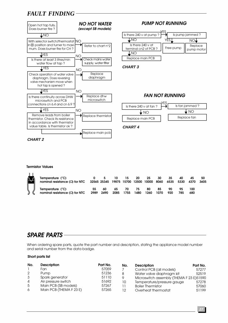
NO HOT WATER
Replace main pcb
Refer to chart n°2
Check mains watersupply, water filter
Is there at least 3 litres/minwater flow at tap ?
Remove leads from boilerthermistor. Check its resistancein accordance with thermistorvalue table. Is thermistor ok ?
Check operation of water valvediaphragm. Does reversing
valve mechanism move whenhot tap is opened ?
Replacediaphragm
Replace thermistor
Open hot tap fully.Does burner fire ?
YES
NO
NO
YES
YES
NO
With selector switch/thermostatin position and turner to maxi-mum. Does burner fire for CH ?
Is there continuity across DHWmicroswitch and PCB
connections cn 6.4 and cn 6.9 ?
YES
Replace dhwmicroswitch
Is there 240 v at pump ?YES
Is there 240 v atterminal cn2 of PCB ?
Is there 240 v at fan ?
NO
YES
CHART 2
NO
NO
NO
CHART 3
PUMP NOT RUNNING
FAN NOT RUNNING
Replace main PCB
YES
CHART 4
NO
NO
Is pump jammed ?
Replacepump motor
NO
Free pump
Replace main PCB
Is fan jammed ?
Replace fan
NO
SPARE PARTSWhen ordering spare parts, quote the part number and description, stating the appliance model numberand serial number from the data badge.
Short parts list
No. Description Part No.1 Fan 570592 Pump 512363 Spark generator 511104 Air pressure switch 516925 Main PCB (SB models) 572676 Main PCB (THEMA F 23 E) 57265
No. Description Part No.7 Control PCB (all models) 572778 Water valve diaphragm kit 525199 Microswitch assembly (THEMA F 23 E)5159010 Temperature/pressure gauge 5727811 Boiler Thermistor 5706012 Overheat thermostat 51199
Temperature (°C) 0 5 10 15 20 25 30 35 40 45 50nominal resistance (Ω) for NTC 32565 25345 19875 15700 12500 10000 8060 6535 5330 4370 3605
Temperature (°C) 55 60 65 70 75 80 85 90 95 100nominal resistance (Ω) for NTC 2989 2490 2085 1755 1480 1260 1070 920 785 680
Termistor Values
(except SB models)

28 108198 B 06/98