Embed Size (px)
Citation preview
SCALANCE W786 outdoor access point
___________________
___________________
___________________
___________________
___________________
___________________
___________________
___________________
SIMATIC NET
Industrial Wireless LAN SCALANCE W786 outdoor access point
Operating Instructions
06/2013 A5E02280428-08
Information on the Internet 1
Safety instructions 2
Introduction 3
Description 4
Mounting 5
Connecting up 6
Technical specifications 7
Certification 8
Siemens AG Industry Sector Postfach 48 48 90026 NÜRNBERG GERMANY
Order number: A5E02280428-08 Ⓟ 07/2013 Technical data subject to change
Copyright © Siemens AG 2008 - 2013. All rights reserved
Legal information Warning notice system
This manual contains notices you have to observe in order to ensure your personal safety, as well as to prevent damage to property. The notices referring to your personal safety are highlighted in the manual by a safety alert symbol, notices referring only to property damage have no safety alert symbol. These notices shown below are graded according to the degree of danger.
DANGER indicates that death or severe personal injury will result if proper precautions are not taken.
WARNING indicates that death or severe personal injury may result if proper precautions are not taken.
CAUTION indicates that minor personal injury can result if proper precautions are not taken.
NOTICE indicates that property damage can result if proper precautions are not taken.
If more than one degree of danger is present, the warning notice representing the highest degree of danger will be used. A notice warning of injury to persons with a safety alert symbol may also include a warning relating to property damage.
Qualified Personnel The product/system described in this documentation may be operated only by personnel qualified for the specific task in accordance with the relevant documentation, in particular its warning notices and safety instructions. Qualified personnel are those who, based on their training and experience, are capable of identifying risks and avoiding potential hazards when working with these products/systems.
Proper use of Siemens products Note the following:
WARNING Siemens products may only be used for the applications described in the catalog and in the relevant technical documentation. If products and components from other manufacturers are used, these must be recommended or approved by Siemens. Proper transport, storage, installation, assembly, commissioning, operation and maintenance are required to ensure that the products operate safely and without any problems. The permissible ambient conditions must be complied with. The information in the relevant documentation must be observed.
Trademarks All names identified by ® are registered trademarks of Siemens AG. The remaining trademarks in this publication may be trademarks whose use by third parties for their own purposes could violate the rights of the owner.
Disclaimer of Liability We have reviewed the contents of this publication to ensure consistency with the hardware and software described. Since variance cannot be precluded entirely, we cannot guarantee full consistency. However, the information in this publication is reviewed regularly and any necessary corrections are included in subsequent editions.
SCALANCE W786 outdoor access point Operating Instructions, 06/2013, A5E02280428-08 3
Contents
1 Information on the Internet ...................................................................................................................... 5
2 Safety instructions ................................................................................................................................... 7
2.1 General safety information for the SCALANCE W786 .................................................................. 7
3 Introduction ............................................................................................................................................. 9
3.1 Information on the Operating Instructions ...................................................................................... 9
3.2 Type designations ........................................................................................................................ 10
4 Description ............................................................................................................................................ 13
4.1 Scope of delivery.......................................................................................................................... 13
4.2 LED display .................................................................................................................................. 13
4.3 Reset button ................................................................................................................................. 17
5 Mounting ............................................................................................................................................... 19
5.1 Removing / fitting the housing cover ............................................................................................ 19
5.2 Connecting up cables .................................................................................................................. 21
5.3 Mounting without an adapter (wall mounting only) ...................................................................... 24
5.4 Mounting with mounting plate ...................................................................................................... 26 5.4.1 Fitting the mounting plate to a wall .............................................................................................. 26 5.4.2 Screwing the cover plate for the cable feedthrough to the mounting plate ................................. 28 5.4.3 Fitting the mounting plate to an S7-300 standard rail .................................................................. 29 5.4.4 Fitting the mounting plate to a DIN rail ........................................................................................ 30 5.4.5 Fitting the mounting plate to a mast ............................................................................................. 31 5.4.6 Fitting/removing the SCALANCE W786 to/from a mounting plate .............................................. 32
6 Connecting up ....................................................................................................................................... 35
6.1 Lightning protection, power supply, and grounding ..................................................................... 35
6.2 Suitable cables for the SCALANCE W786 .................................................................................. 40
6.3 Connecting the cables ................................................................................................................. 42
6.4 Connectors for the power supply of the SCALANCE W786 ........................................................ 45
6.5 Connecting a power supply adapter ............................................................................................ 47
6.6 Connection for Industrial Ethernet ............................................................................................... 51
6.7 Connectors for external antennas ................................................................................................ 52
6.8 Inserting / removing the C-PLUG ................................................................................................. 53
7 Technical specifications ........................................................................................................................ 55
7.1 SCALANCE W786 technical specifications ................................................................................. 55
7.2 Dimension drawing SCALANCE W786 ....................................................................................... 59
Contents
SCALANCE W786 outdoor access point 4 Operating Instructions, 06/2013, A5E02280428-08
7.3 Permitted antennas ..................................................................................................................... 60
7.4 Radiation patterns diagrams of SCALANCE W786 internal antennas ....................................... 61
8 Certification ........................................................................................................................................... 65
8.1 Approvals for SCALANCE W786 ................................................................................................ 65
8.2 National approvals ...................................................................................................................... 77

SCALANCE W786 outdoor access point Operating Instructions, 06/2013, A5E02280428-08 5
Information on the Internet 1
Bitte beachten Sie die Warnhinweise und zusätzlichen Informationen in der Betriebsanleitung (kompakt) in Ihrer Sprache im Internet: http://support.automation.siemens.com/ww/view/at/10806097 http://support.automation.siemens.com/ww/view/ch/10806097 http://support.automation.siemens.com/ww/view/de/10806097 http://support.automation.siemens.com/ww/view/li/10806097 http://support.automation.siemens.com/ww/view/lu/10806097
Please observe the warnings and additional information in the user manual (compact) in your language in the Internet: http://support.automation.siemens.com/ww/view/au/10806097 http://support.automation.siemens.com/ww/view/ca/10806097 http://support.automation.siemens.com/ww/view/gb/10806097 http://support.automation.siemens.com/ww/view/ie/10806097 http://support.automation.siemens.com/ww/view/us/10806097 http://support.automation.siemens.com/ww/view/za/10806097
Veuillez observer les avertissements et informations supplémentaires du manuel d’utilisation (compact) dans votre langue dans l’internet: http://support.automation.siemens.com/ww/view/be/10806097 http://support.automation.siemens.com/ww/view/ch/10806097 http://support.automation.siemens.com/ww/view/fr/10806097 http://support.automation.siemens.com/ww/view/lu/10806097
Osservare le avvertenze di sicurezza e le informazioni aggiuntive nel manuale d'istruzioni (compatto) nella propria lingua in Internet: http://support.automation.siemens.com/ww/view/it/10806097
Por favor, observe las indicaciones de advertencia y las informaciones adicionales en las instrucciones de servicio (compactas) en su idioma disponibles en Internet: http://support.automation.siemens.com/ww/view/cl/10806097 http://support.automation.siemens.com/ww/view/es/10806097
Berte prosím v úvahu výstražné pokyny a dodatečné informace v provozním návodu (kompakt) na internetu ve vaší řeči: http://support.automation.siemens.com/ww/view/cz/10806097
De bedes iagttage advarselsanvisningerne og de yderligere informationer i betjeningsvejledningen (kompakt) for Deres sprog på internettet: http://support.automation.siemens.com/ww/view/dk/10806097
Huomioi internetissä oman kielisessäsi käyttöohjeessa (kompakti) olevat varoitusohjeet ja lisäinformaatiot: http://support.automation.siemens.com/ww/view/fi/10806097
Προσέξτε παρακαλώ τις προειδοποιητικές υποδείξεις και τις πρόσθετες πληροφορίες στις οδηγίες λειτουργίας (συνεπτηγμένες) στη γλώσσα σας στο διαδίκτυο. http://support.automation.siemens.com/ww/view/gr/10806097
Information on the Internet
SCALANCE W786 outdoor access point 6 Operating Instructions, 06/2013, A5E02280428-08
请遵守互联网上用您的语言编写的用户手册(简易版)中的警告信息和附加说明: http://support.automation.siemens.com/ww/view/cn/10806097 http://support.automation.siemens.com/ww/view/hk/10806097 http://support.automation.siemens.com/ww/view/sg/10806097
Kérjük, vegye figyelembe az Interneten található magyar nyelvű használati utasításban (kompakt) olvasható figyelmeztető utasításokat és a kiegészítő információkat! http://support.automation.siemens.com/ww/view/hu/10806097
Vinsamlegast athugið varúðarábendingar og viðbótarupplýsingar í notendahandbókinni (stytt útgáfa) á Netinu: http://support.automation.siemens.com/ww/view/is/10806097
以下のインターネットアドレスでお客様の言語による取扱説明書(コンパクト版)をご覧 http://support.automation.siemens.com/ww/view/jp/10806097 いただけます。同取扱説明書内に記載された警告事項および補足情報にご注意ください。
인터넷 http://support.automation.siemens.com/ww/view/kr/10806097에서 귀하의 사용 언어로 된 사용자 설명서(컴팩트)의 경고 및 추가 정보를 확인하십시오.
ىلإ هبنتلا بجي صخلملا ليغشتلا ليلد يف ةروكذملا ةيفاضإلا تامولعملا و ريذحتلا ثاداشرا يف ةروكذملا ةيفاضإلا تامولعملا و ريذحتلا تنرتنالا ةكبش ىلع دوجوملا و مكتغلب تنرتنالا ةكبش ىلع دوجوملا و مكتغلب صخلملا ليغشتلا ليلدhttp://support.automation.siemens.com/ww/view/kw/10806097
Neem de waarschuwingen en de bijkomende informatie in acht, te vinden in de handleiding (compact) in uw taal in het internet: http://support.automation.siemens.com/ww/view/be/10806097 http://support.automation.siemens.com/ww/view/nl/10806097
Vennligst se advarsler og ytterligere opplysninger i driftsveiledningen (kompakt) på ditt språk i Internett: http://support.automation.siemens.com/ww/view/no/10806097
Por favor observe as advertências e as informações adicionais no manual de instruções (compacto) na sua língua na internet: http://support.automation.siemens.com/ww/view/po/10806097
Var vänlig observera varningarna och tilläggsinformationerna i bruksanvisningen (kompakt) på ditt språk på Internet: http://support.automation.siemens.com/ww/view/se/10806097
Lütfen internette sizin dilinizde sunulan işletme kılavuzundaki (yoğunlaştırılmış) uyarı bilgilerine ve ek bilgilere dikkat ediniz: http://support.automation.siemens.com/ww/view/tr/10806097
SCALANCE W786 outdoor access point Operating Instructions, 06/2013, A5E02280428-08 7
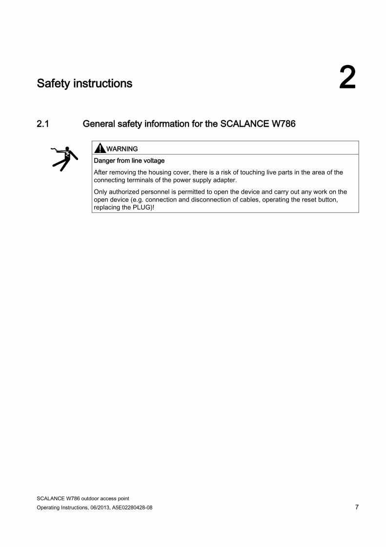
Safety instructions 2 2.1 General safety information for the SCALANCE W786
WARNING
Danger from line voltage
After removing the housing cover, there is a risk of touching live parts in the area of the connecting terminals of the power supply adapter.
Only authorized personnel is permitted to open the device and carry out any work on the open device (e.g. connection and disconnection of cables, operating the reset button, replacing the PLUG)!

Safety instructions 2.1 General safety information for the SCALANCE W786
SCALANCE W786 outdoor access point 8 Operating Instructions, 06/2013, A5E02280428-08
SCALANCE W786 outdoor access point Operating Instructions, 06/2013, A5E02280428-08 9
Introduction 3 3.1 Information on the Operating Instructions
Validity of the Operating Instructions (compact) These operating instructions cover the following products:
● SCALANCE W786-1PRO
● SCALANCE W786-2PRO
● SCALANCE W786-3PRO
● SCALANCE W786-2RR
These operating instructions apply to the following software version:
● SCALANCE W786 firmware as of version 4.4 Hardware version AS 3 (RJ-45 interface) Hardware version AS 4 (fiber-optic interface)
Note
These Operating Instructions do not apply to the SCALANCE W786-2HPW.
Purpose of the Operating Instructions Using the Operating Instructions, you will be able to install and connect the SCALANCE W786 correctly. Configuring the SCALANCE W786 and integrating the SCALANCE W786 in a WLAN are not dealt with in this manual.
Documentation on the accompanying CD You will find detailed information on configuration in the configuration manual SCALANCE W-700 on the accompanying CD in the file:
PH_SCALANCE-W-700_76.pdf
Note
Make sure that you read the explanations and instructions in the README.txt file
Introduction 3.2 Type designations
SCALANCE W786 outdoor access point 10 Operating Instructions, 06/2013, A5E02280428-08
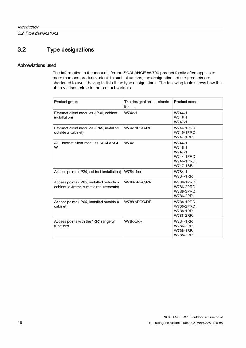
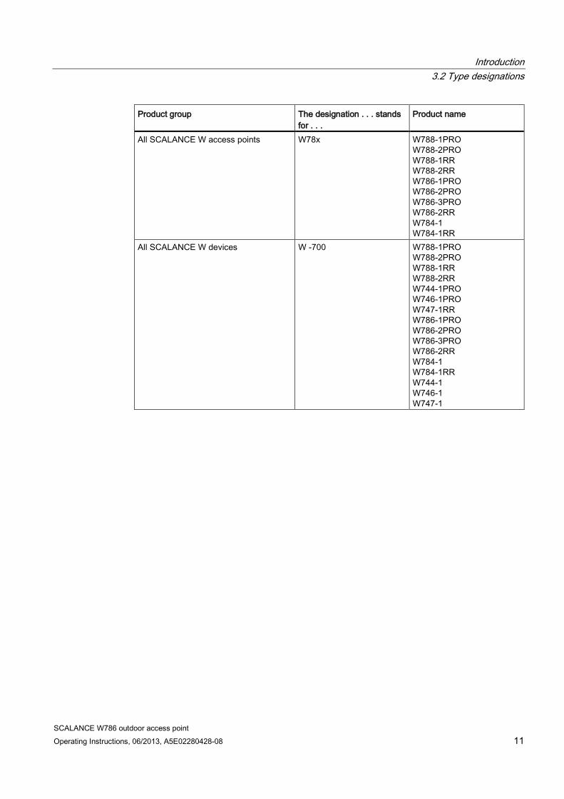
3.2 Type designations
Abbreviations used The information in the manuals for the SCALANCE W-700 product family often applies to more than one product variant. In such situations, the designations of the products are shortened to avoid having to list all the type designations. The following table shows how the abbreviations relate to the product variants.
Product group The designation . . . stands
for . . . Product name
Ethernet client modules (IP30, cabinet installation)
W74x-1 W744-1 W746-1 W747-1
Ethernet client modules (IP65, installed outside a cabinet)
W74x-1PRO/RR W744-1PRO W746-1PRO W747-1RR
All Ethernet client modules SCALANCE W
W74x W744-1 W746-1 W747-1 W744-1PRO W746-1PRO W747-1RR
Access points (IP30, cabinet installation) W784-1xx W784-1 W784-1RR
Access points (IP65, installed outside a cabinet, extreme climatic requirements)
W786-xPRO/RR W786-1PRO W786-2PRO W786-3PRO W786-2RR
Access points (IP65, installed outside a cabinet)
W788-xPRO/RR W788-1PRO W788-2PRO W788-1RR W788-2RR
Access points with the "RR" range of functions
W78x-xRR W784-1RR W786-2RR W788-1RR W788-2RR
Introduction 3.2 Type designations
SCALANCE W786 outdoor access point Operating Instructions, 06/2013, A5E02280428-08 11
Product group The designation . . . stands for . . .
Product name
All SCALANCE W access points W78x W788-1PRO W788-2PRO W788-1RR W788-2RR W786-1PRO W786-2PRO W786-3PRO W786-2RR W784-1 W784-1RR
All SCALANCE W devices W -700 W788-1PRO W788-2PRO W788-1RR W788-2RR W744-1PRO W746-1PRO W747-1RR W786-1PRO W786-2PRO W786-3PRO W786-2RR W784-1 W784-1RR W744-1 W746-1 W747-1

Introduction 3.2 Type designations
SCALANCE W786 outdoor access point 12 Operating Instructions, 06/2013, A5E02280428-08
SCALANCE W786 outdoor access point Operating Instructions, 06/2013, A5E02280428-08 13
Description 4 4.1 Scope of delivery
4.2 LED display
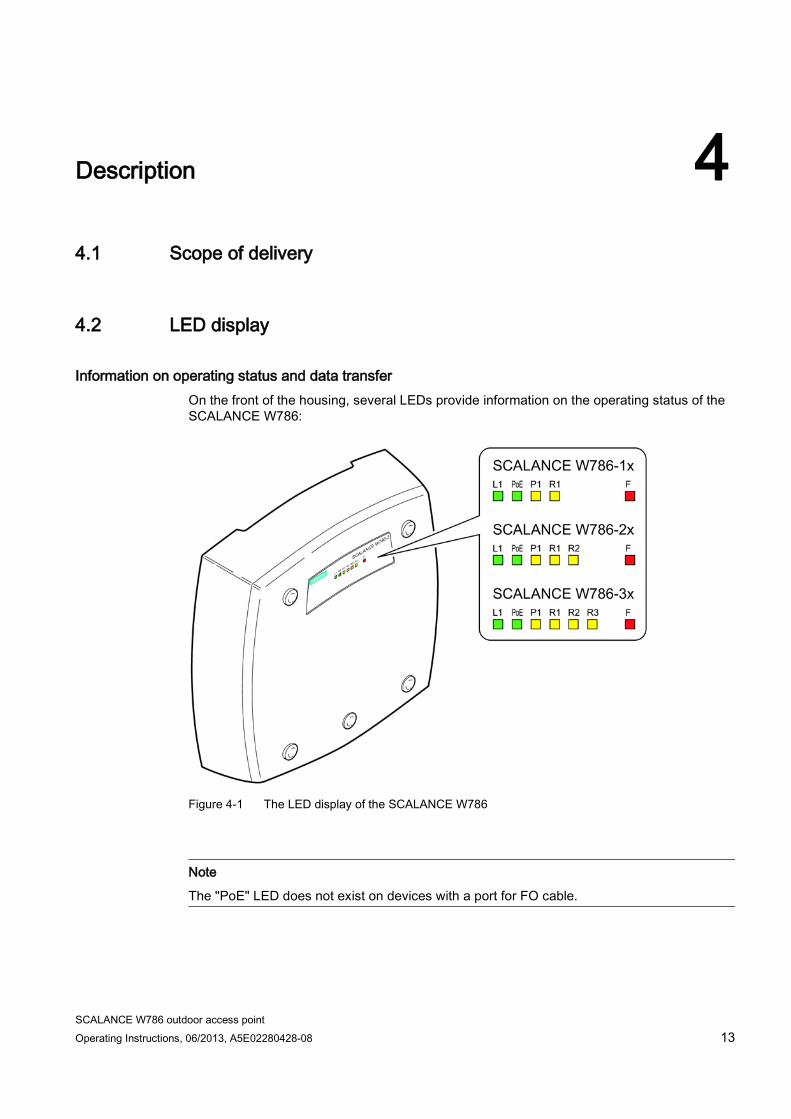
Information on operating status and data transfer On the front of the housing, several LEDs provide information on the operating status of the SCALANCE W786:
Figure 4-1 The LED display of the SCALANCE W786
Note
The "PoE" LED does not exist on devices with a port for FO cable.

Description 4.2 LED display
SCALANCE W786 outdoor access point 14 Operating Instructions, 06/2013, A5E02280428-08
LED Color Meaning L1 Green Power supply over a power supply adapter or the 48 V DC energy
contacts of devices with a port for FO cable. PoE Green Power over Ethernet or power over the 48 V DC energy contacts of
devices with an RJ-45 port. P1 Yellow Data transfer over the Ethernet interface (traffic).
Green There is a connection over the Ethernet port. (Link). Flashing yellow PRESET-PLUG detected. Yellow/green PRESET function completed successfully. Flashing green "Flashing" enabled over PST.
R1 Yellow Data transfer over the first WLAN interface. Green Access Point Mode:
The WLAN interface is initialized and ready for operation. Client Mode: There is a connection over the first WLAN port.
Flashing green Access Point Mode: The channels are being scanned. Client Mode: The client is searching for a connection to an access point or ad hoc network.
Green flashing quickly
Access Point Mode: With 802.11h, the channel is scanned for one minute for primary users before the channel can be used for data traffic. Client Mode: The client waits for the adopt MAC address due to the setting <Auto Find Adopt MAC> and is connected to no access point.
Green 3x fast, 1x long flashing
Client Mode: The client waits for the adopt MAC address due to the setting <Auto Find Adopt MAC> and is connected to an access point.
Flashing yellow PRESET-PLUG detected. Yellow/green PRESET function completed successfully.
R2 Yellow Access Point Mode: Data transfer over the second WLAN port. Client Mode: The LED is always off because the 2nd port is not available in client mode.
Green Access Point Mode: The WLAN interface is initialized and ready for operation. Client Mode: The LED is always off because the 2nd port is not available in client mode.
Flashing green Access Point Mode: The channels are being scanned. Client Mode: The LED is always off because the 2nd port is not available in client mode.
Description 4.2 LED display
SCALANCE W786 outdoor access point Operating Instructions, 06/2013, A5E02280428-08 15
LED Color Meaning Green flashing quickly
Access Point Mode: With 802.11h, the channel is scanned for one minute for primary users before the channel can be used for data traffic. Client Mode: The LED is always off because the 2nd port is not available in client mode.
Flashing yellow PRESET-PLUG detected. Yellow/green PRESET function completed successfully.
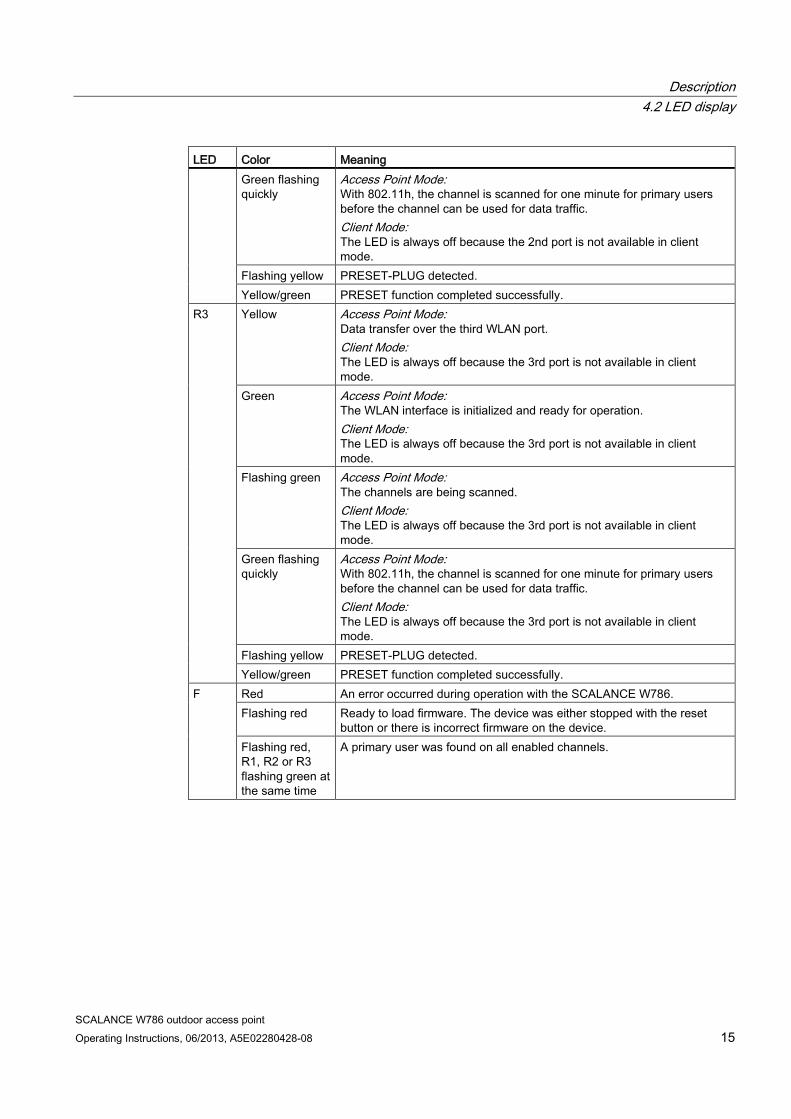
R3 Yellow Access Point Mode: Data transfer over the third WLAN port. Client Mode: The LED is always off because the 3rd port is not available in client mode.
Green Access Point Mode: The WLAN interface is initialized and ready for operation. Client Mode: The LED is always off because the 3rd port is not available in client mode.
Flashing green Access Point Mode: The channels are being scanned. Client Mode: The LED is always off because the 3rd port is not available in client mode.
Green flashing quickly
Access Point Mode: With 802.11h, the channel is scanned for one minute for primary users before the channel can be used for data traffic. Client Mode: The LED is always off because the 3rd port is not available in client mode.
Flashing yellow PRESET-PLUG detected. Yellow/green PRESET function completed successfully.
F Red An error occurred during operation with the SCALANCE W786. Flashing red Ready to load firmware. The device was either stopped with the reset
button or there is incorrect firmware on the device. Flashing red, R1, R2 or R3 flashing green at the same time
A primary user was found on all enabled channels.
Description 4.2 LED display
SCALANCE W786 outdoor access point 16 Operating Instructions, 06/2013, A5E02280428-08
Note
If the LED for the WLAN port is not green when the device starts up, although it is activated, the port is not ready for operation (interface not initialized).
The main reason for this is usually that during commissioning of the SCALANCE W78x products, a waiting time of up to 15 minutes can occur when the ambient temperature is below zero. The device is ready for operation at the specified ambient temperature as soon as the LED for the WLAN interface is lit green.
Note Primary user (radar) on all enabled channels
If the device detects a primary user on all enabled channels (for example radio waves of a radar station), the LEDs F and R1 flash. No data traffic is then possible for the next 30 minutes. After this time, the device runs the scan again and checks whether a primary user still exists. If no primary user is detected, data traffic is possible again.
The wait time of 30 minutes is necessary due to legal requirements and cannot be shortened even by resetting the device.
Description 4.3 Reset button
SCALANCE W786 outdoor access point Operating Instructions, 06/2013, A5E02280428-08 17
4.3 Reset button
WARNING
Danger from line voltage
Once you have removed the housing cover, there is the danger from line voltage in the area of the connecting terminals on the power supply adapter.
Only authorized personnel is permitted to open the device and carry out any work on the open device (e.g. connection and disconnection of lines, operating the reset button, replacing the C-PLUG)!
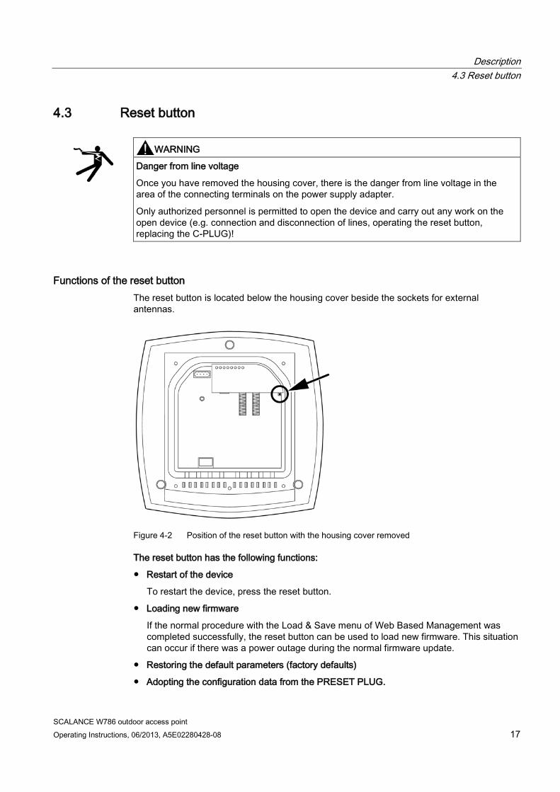
Functions of the reset button The reset button is located below the housing cover beside the sockets for external antennas.
Figure 4-2 Position of the reset button with the housing cover removed
The reset button has the following functions:
● Restart of the device
To restart the device, press the reset button.
● Loading new firmware
If the normal procedure with the Load & Save menu of Web Based Management was completed successfully, the reset button can be used to load new firmware. This situation can occur if there was a power outage during the normal firmware update.
● Restoring the default parameters (factory defaults)
● Adopting the configuration data from the PRESET PLUG.

Description 4.3 Reset button
SCALANCE W786 outdoor access point 18 Operating Instructions, 06/2013, A5E02280428-08
SCALANCE W786 outdoor access point Operating Instructions, 06/2013, A5E02280428-08 19
Mounting 5 5.1 Removing / fitting the housing cover
When does the housing cover need to be removed? You can only perform the following activities when the cover is removed.
● You want to screw the SCALANCE W786 to a wall or onto the optional mounting plate.
● You want to connect cables to the SCALANCE W786 for the power supply, for Ethernet or for external antennas.
● You want to insert a PLUG in the device or replace an existing PLUG.
● You want to use the reset button.
Removing the housing cover
WARNING
Danger from line voltage
After removing the housing cover, there is a risk of touching live parts in the area of the connecting terminals of the power supply adapter.
Only authorized personnel is permitted to open the device and carry out any work on the open device (e.g. connection and disconnection of cables, operating the reset button, replacing the PLUG)!
Mounting 5.1 Removing / fitting the housing cover
SCALANCE W786 outdoor access point 20 Operating Instructions, 06/2013, A5E02280428-08
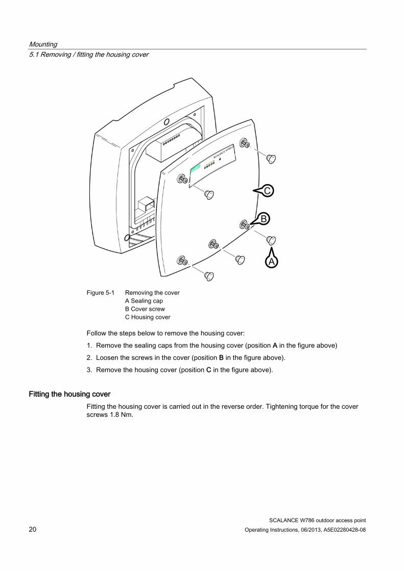
Figure 5-1 Removing the cover
A Sealing cap B Cover screw C Housing cover
Follow the steps below to remove the housing cover:
1. Remove the sealing caps from the housing cover (position A in the figure above)
2. Loosen the screws in the cover (position B in the figure above).
3. Remove the housing cover (position C in the figure above).
Fitting the housing cover Fitting the housing cover is carried out in the reverse order. Tightening torque for the cover screws 1.8 Nm.
Mounting 5.2 Connecting up cables
SCALANCE W786 outdoor access point Operating Instructions, 06/2013, A5E02280428-08 21
5.2 Connecting up cables
Connecting up cables prior to mounting Before you screw a SCALANCE W786 to a wall or to the optional mounting plate, the cables for the power supply, for Ethernet, and, when necessary, for the external antennas must be connected up first. The available options are as follows:
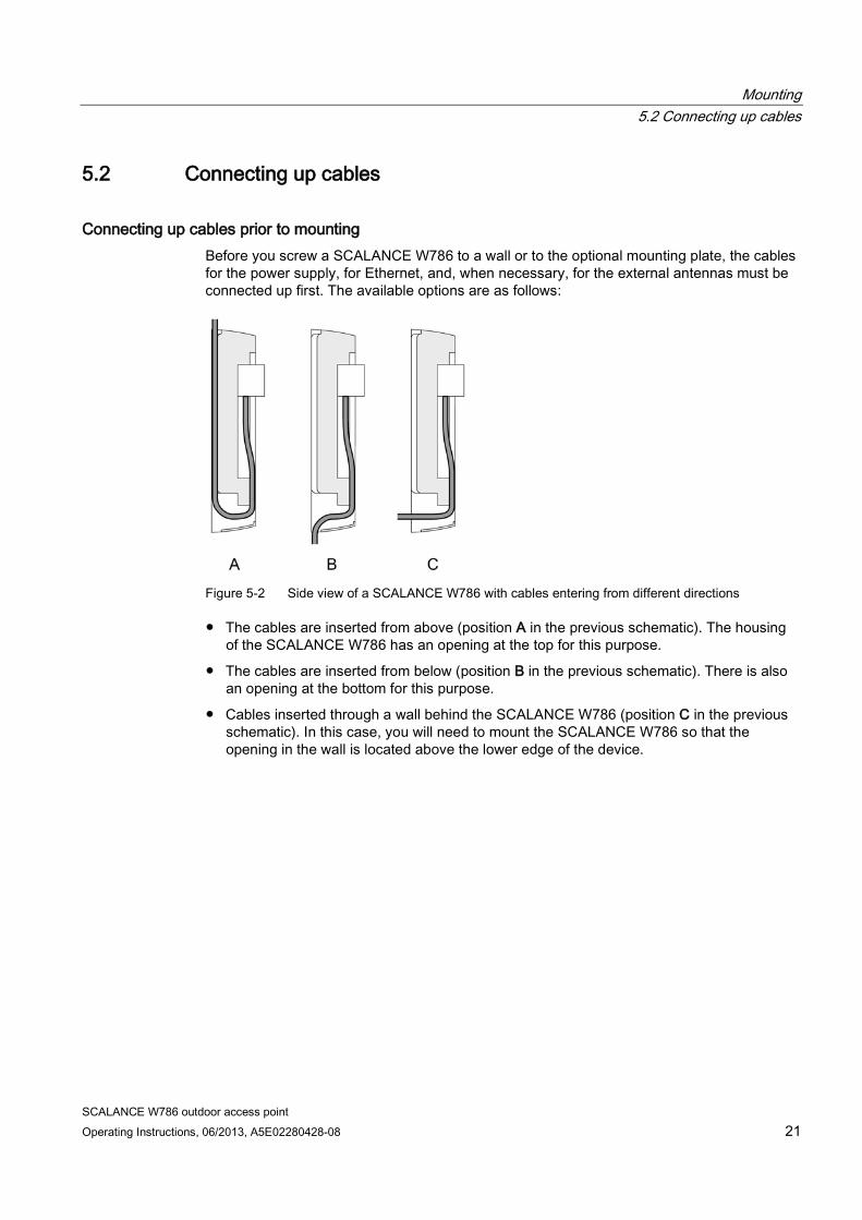
Figure 5-2 Side view of a SCALANCE W786 with cables entering from different directions
● The cables are inserted from above (position A in the previous schematic). The housing of the SCALANCE W786 has an opening at the top for this purpose.
● The cables are inserted from below (position B in the previous schematic). There is also an opening at the bottom for this purpose.
● Cables inserted through a wall behind the SCALANCE W786 (position C in the previous schematic). In this case, you will need to mount the SCALANCE W786 so that the opening in the wall is located above the lower edge of the device.
Mounting 5.2 Connecting up cables
SCALANCE W786 outdoor access point 22 Operating Instructions, 06/2013, A5E02280428-08
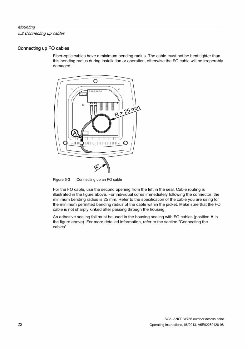
Connecting up FO cables Fiber-optic cables have a minimum bending radius. The cable must not be bent tighter than this bending radius during installation or operation, otherwise the FO cable will be irreperably damaged.
Figure 5-3 Connecting up an FO cable
For the FO cable, use the second opening from the left in the seal. Cable routing is illustrated in the figure above. For individual cores immediately following the connector, the minimum bending radius is 25 mm. Refer to the specification of the cable you are using for the minimum permitted bending radius of the cable within the jacket. Make sure that the FO cable is not sharply kinked after passing through the housing.
An adhesive sealing foil must be used in the housing sealing with FO cables (position A in the figure above). For more detailed information, refer to the section "Connecting the cables".
Mounting 5.2 Connecting up cables
SCALANCE W786 outdoor access point Operating Instructions, 06/2013, A5E02280428-08 23
Grounding terminal
WARNING
To operate the SCALANCE W786 safely, the chassis ground connector must have a suitable cable connected. Do not use the SCALANCE W786 without a ground cable connected.
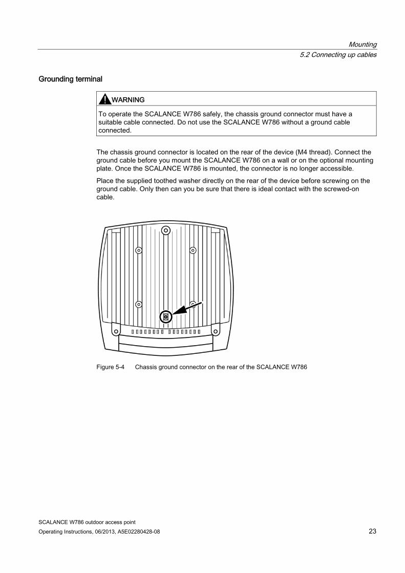
The chassis ground connector is located on the rear of the device (M4 thread). Connect the ground cable before you mount the SCALANCE W786 on a wall or on the optional mounting plate. Once the SCALANCE W786 is mounted, the connector is no longer accessible.
Place the supplied toothed washer directly on the rear of the device before screwing on the ground cable. Only then can you be sure that there is ideal contact with the screwed-on cable.
Figure 5-4 Chassis ground connector on the rear of the SCALANCE W786
Mounting 5.3 Mounting without an adapter (wall mounting only)
SCALANCE W786 outdoor access point 24 Operating Instructions, 06/2013, A5E02280428-08
5.3 Mounting without an adapter (wall mounting only)
Drilling template
Note Installation location
The following should be noted with regard to the installation location: • Devices with an internal antenna must be aligned according to the characteristics of the
internal antenna (refer to the technical specifications of the antenna --> Radiation pattern diagrams). Since the internal antennas are integrated in the housing, the location and alignment of the housing decides the radiation direction of the antennas.
• There are no restrictions relating to devices without internal antennas.
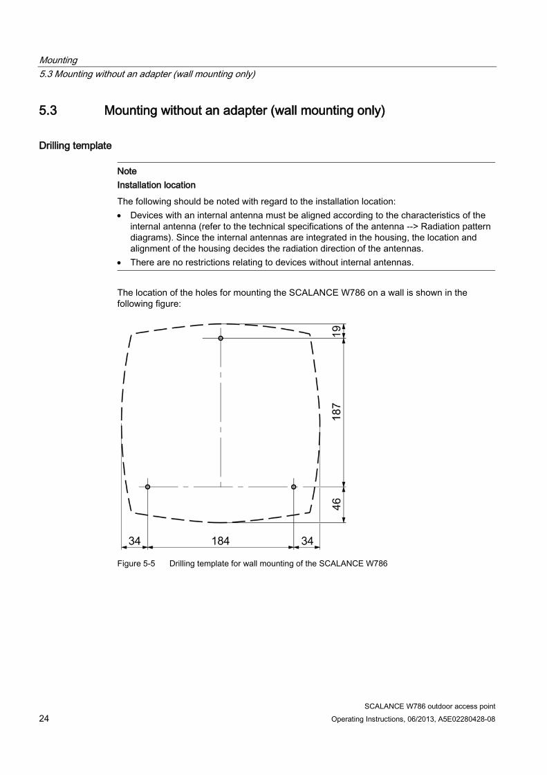
The location of the holes for mounting the SCALANCE W786 on a wall is shown in the following figure:
Figure 5-5 Drilling template for wall mounting of the SCALANCE W786
Mounting 5.3 Mounting without an adapter (wall mounting only)
SCALANCE W786 outdoor access point Operating Instructions, 06/2013, A5E02280428-08 25
Procedure
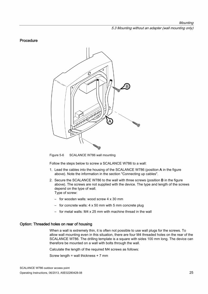
Figure 5-6 SCALANCE W786 wall mounting
Follow the steps below to screw a SCALANCE W786 to a wall:
1. Lead the cables into the housing of the SCALANCE W786 (position A in the figure above). Note the information in the section "Connecting up cables".
2. Secure the SCALANCE W786 to the wall with three screws (position B in the figure above). The screws are not supplied with the device. The type and length of the screws depend on the type of wall. Type of screw:
– for wooden walls: wood screw 4 x 30 mm
– for concrete walls: 4 x 50 mm with 5 mm concrete plug
– for metal walls: M4 x 25 mm with machine thread in the wall
Option: Threaded holes on rear of housing When a wall is extremely thin, it is often not possible to use wall plugs for the screws. To allow wall mounting even in this situation, there are four M4 threaded holes on the rear of the SCALANCE W786. The drilling template is a square with sides 100 mm long. The device can therefore be mounted on a wall with bolts through the wall.
Calculate the length of the required M4 screws as follows:
Screw length = wall thickness + 7 mm
Mounting 5.4 Mounting with mounting plate
SCALANCE W786 outdoor access point 26 Operating Instructions, 06/2013, A5E02280428-08
5.4 Mounting with mounting plate
5.4.1 Fitting the mounting plate to a wall
Drilling template
Note Installation location
The following should be noted with regard to the installation location: • Devices with an internal antenna must be aligned according to the characteristics of the
internal antenna (refer to the technical specifications of the antenna --> Radiation pattern diagrams). Since the internal antennas are integrated in the housing, the location and alignment of the housing decides the radiation direction of the antennas.
• There are no restrictions relating to devices without internal antennas.
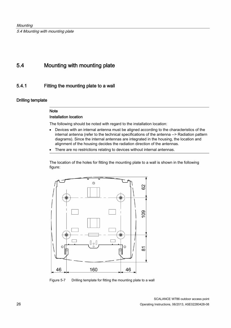
The location of the holes for fitting the mounting plate to a wall is shown in the following figure:
Figure 5-7 Drilling template for fitting the mounting plate to a wall
Mounting 5.4 Mounting with mounting plate
SCALANCE W786 outdoor access point Operating Instructions, 06/2013, A5E02280428-08 27
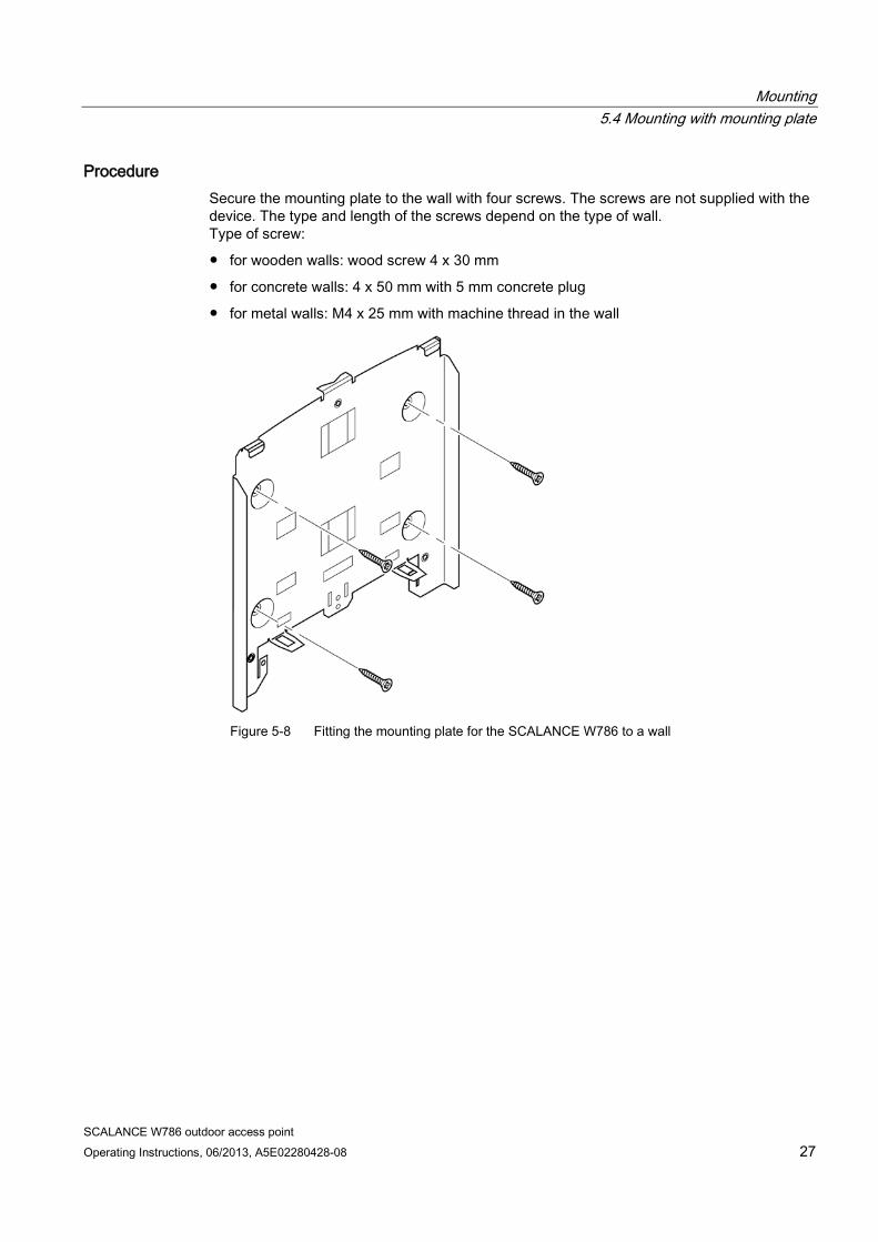
Procedure Secure the mounting plate to the wall with four screws. The screws are not supplied with the device. The type and length of the screws depend on the type of wall. Type of screw:
● for wooden walls: wood screw 4 x 30 mm
● for concrete walls: 4 x 50 mm with 5 mm concrete plug
● for metal walls: M4 x 25 mm with machine thread in the wall
Figure 5-8 Fitting the mounting plate for the SCALANCE W786 to a wall
Mounting 5.4 Mounting with mounting plate
SCALANCE W786 outdoor access point 28 Operating Instructions, 06/2013, A5E02280428-08
5.4.2 Screwing the cover plate for the cable feedthrough to the mounting plate
Protection of the cable feedthrough against strong water jets The cabling of a SCALANCE W786 is led out of the rear of the device. The housing seal is effective only when it is not subjected to water jets. If the device is mounted on a wall, this is the case and no further measures are necessary. When mounted in any other way, except for mounting on an S7-300 standard rail, an additional cover plate must be screwed to the mounting plate.
WARNING
Danger from line voltage
If the cable feedthrough is subjected to strong water jets, water can penetrate the device and create a live connection to the line voltage. There is then a risk of electric shock.
Make sure that you use the cover plate for the cable feedthrough if you do not mount the SCALANCE W786 on a wall.
Procedure
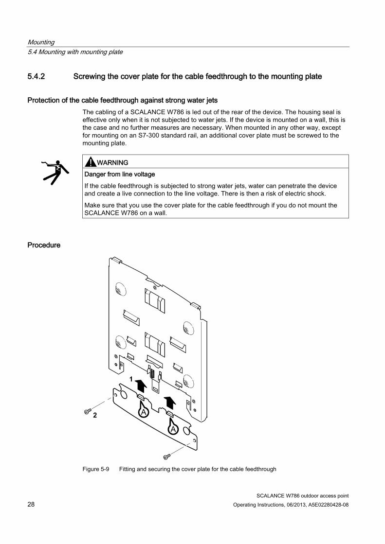
Figure 5-9 Fitting and securing the cover plate for the cable feedthrough
Mounting 5.4 Mounting with mounting plate
SCALANCE W786 outdoor access point Operating Instructions, 06/2013, A5E02280428-08 29
To screw the cover plate for the cable feedthrough to the mounting plate, follow the steps below:
1. Fit the cover plate on the mounting plate from below until the two lugs (position A in the figure above) engage the lower edge of the mounting plate.
2. Secure the cover plate to the mounting plate with two M4 screws. The screws are supplied with the assembly kit.
5.4.3 Fitting the mounting plate to an S7-300 standard rail
Procedure
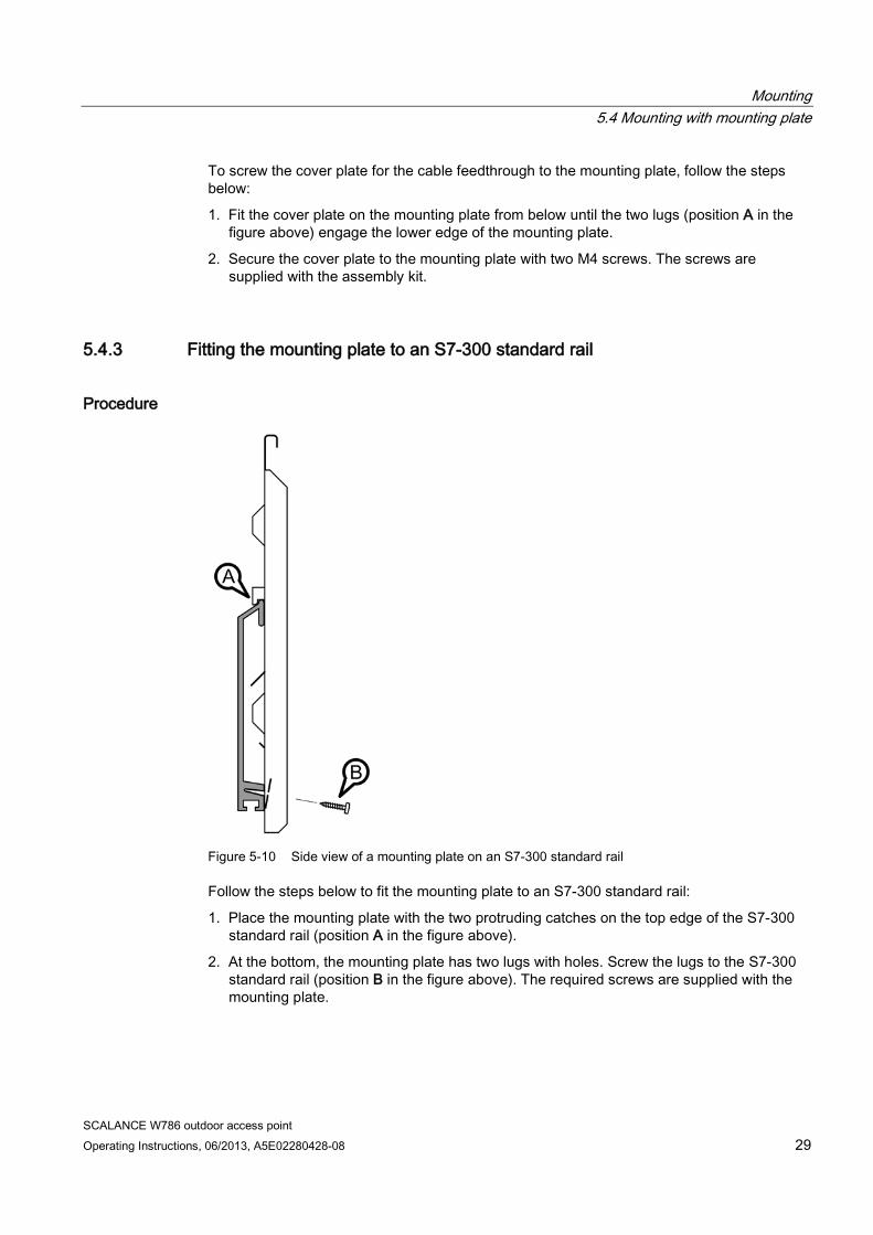
Figure 5-10 Side view of a mounting plate on an S7-300 standard rail
Follow the steps below to fit the mounting plate to an S7-300 standard rail:
1. Place the mounting plate with the two protruding catches on the top edge of the S7-300 standard rail (position A in the figure above).
2. At the bottom, the mounting plate has two lugs with holes. Screw the lugs to the S7-300 standard rail (position B in the figure above). The required screws are supplied with the mounting plate.
Mounting 5.4 Mounting with mounting plate
SCALANCE W786 outdoor access point 30 Operating Instructions, 06/2013, A5E02280428-08
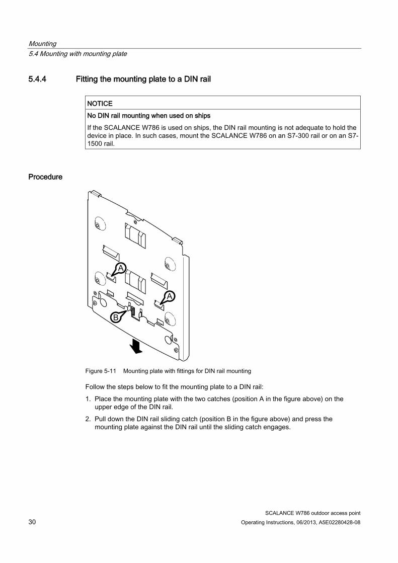
5.4.4 Fitting the mounting plate to a DIN rail
NOTICE
No DIN rail mounting when used on ships
If the SCALANCE W786 is used on ships, the DIN rail mounting is not adequate to hold the device in place. In such cases, mount the SCALANCE W786 on an S7-300 rail or on an S7-1500 rail.
Procedure
Figure 5-11 Mounting plate with fittings for DIN rail mounting
Follow the steps below to fit the mounting plate to a DIN rail:
1. Place the mounting plate with the two catches (position A in the figure above) on the upper edge of the DIN rail.
2. Pull down the DIN rail sliding catch (position B in the figure above) and press the mounting plate against the DIN rail until the sliding catch engages.
Mounting 5.4 Mounting with mounting plate
SCALANCE W786 outdoor access point Operating Instructions, 06/2013, A5E02280428-08 31
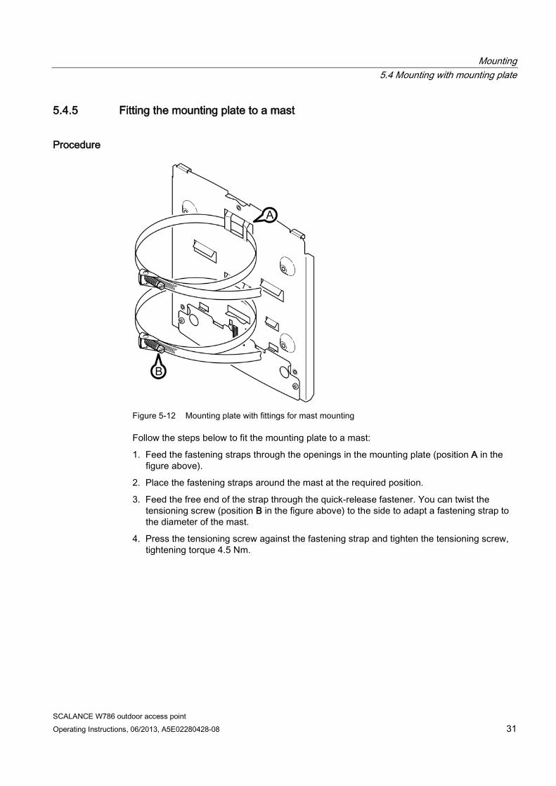
5.4.5 Fitting the mounting plate to a mast
Procedure
Figure 5-12 Mounting plate with fittings for mast mounting
Follow the steps below to fit the mounting plate to a mast:
1. Feed the fastening straps through the openings in the mounting plate (position A in the figure above).
2. Place the fastening straps around the mast at the required position.
3. Feed the free end of the strap through the quick-release fastener. You can twist the tensioning screw (position B in the figure above) to the side to adapt a fastening strap to the diameter of the mast.
4. Press the tensioning screw against the fastening strap and tighten the tensioning screw, tightening torque 4.5 Nm.
Mounting 5.4 Mounting with mounting plate
SCALANCE W786 outdoor access point 32 Operating Instructions, 06/2013, A5E02280428-08
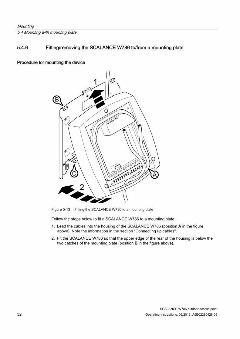
5.4.6 Fitting/removing the SCALANCE W786 to/from a mounting plate
Procedure for mounting the device
Figure 5-13 Fitting the SCALANCE W786 to a mounting plate
Follow the steps below to fit a SCALANCE W786 to a mounting plate:
1. Lead the cables into the housing of the SCALANCE W786 (position A in the figure above). Note the information in the section "Connecting up cables".
2. Fit the SCALANCE W786 so that the upper edge of the rear of the housing is below the two catches of the mounting plate (position B in the figure above).
Mounting 5.4 Mounting with mounting plate
SCALANCE W786 outdoor access point Operating Instructions, 06/2013, A5E02280428-08 33
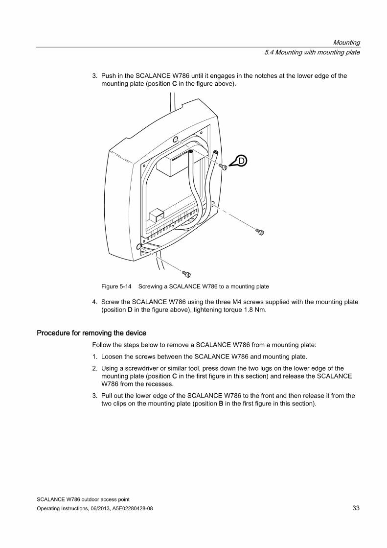
3. Push in the SCALANCE W786 until it engages in the notches at the lower edge of the mounting plate (position C in the figure above).
Figure 5-14 Screwing a SCALANCE W786 to a mounting plate
4. Screw the SCALANCE W786 using the three M4 screws supplied with the mounting plate (position D in the figure above), tightening torque 1.8 Nm.
Procedure for removing the device Follow the steps below to remove a SCALANCE W786 from a mounting plate:
1. Loosen the screws between the SCALANCE W786 and mounting plate.
2. Using a screwdriver or similar tool, press down the two lugs on the lower edge of the mounting plate (position C in the first figure in this section) and release the SCALANCE W786 from the recesses.
3. Pull out the lower edge of the SCALANCE W786 to the front and then release it from the two clips on the mounting plate (position B in the first figure in this section).

Mounting 5.4 Mounting with mounting plate
SCALANCE W786 outdoor access point 34 Operating Instructions, 06/2013, A5E02280428-08
SCALANCE W786 outdoor access point Operating Instructions, 06/2013, A5E02280428-08 35
Connecting up 6 6.1 Lightning protection, power supply, and grounding
Notes on lightning protection
WARNING
Danger due to lightning strikes
Antennas installed outdoors must be within the area covered by a lightning protection system. Make sure that all conducting systems entering from outdoors can be protected by a lightning protection potential equalization system.
When implementing your lightning protection concept, make sure you adhere to the VDE 0182 or IEC 62305 standard.
Suitable lightning conductors are available in the range of accessories of SIMATIC NET Industrial WLAN:
Lightning protector LP798-2N (order no. 6GK5798-2LP10-2AA6 is the most suitable version)
Lightning protector LP798-1N (order no. 6GK5798-2LP00-2AA6)
WARNING
Danger due to lightning strikes
Installing one of these lightning protectors between an antenna and a SCALANCE W-700 is not adequate protection against a lightning strike. The LP798-2N and LP798-1N lightening protectors only work within the framework of a comprehensive lightning protection concept. If you have questions, ask a qualified specialist company.
Note
The requirements of EN61000-4-5, surge immunity tests on power supply lines, are met only when a Blitzductor is used with 12 - 24 V DC and 48 V DC:
12 - 24 V DC: VT AD 24V type no. 918 402
48 V DC: BXT ML2 BD S48, Part no. 920245 BXT BAS, Part no. 920300 (base)
Manufacturer: DEHN+SÖHNE GmbH+Co.KG, Hans Dehn Str. 1, Postfach 1640, D - 92306 Neumarkt, Germany
Connecting up 6.1 Lightning protection, power supply, and grounding
SCALANCE W786 outdoor access point 36 Operating Instructions, 06/2013, A5E02280428-08
Note 48 V lightning protector
When using the 48 V DC lightning protector, the power supply must be fused with 1 A.
Safety extra low voltage
WARNING
Danger to life from overvoltage, fire hazard
The equipment is designed for operation with Safety Extra Low Voltage, SELV by a Limited Power Source, LPS. (This does not apply to 100 V ... 240 V devices.)
This means that only Safety Extra Low Voltage (SELV) with Limited Power Source, LPS complying with EN60950 / EN 60950-1 / VDE0805 must be connected to the power supply terminals. The power supply unit for the equipment power supply must comply with NEC Class 2, as described by the National Electrical Code (r) (ANSI / NFPA 70).
If the equipment is connected to a redundant power supply (two separate power supplies), both must meet these requirements.
Exception:
Power supply with PELV (according to VDE 0100-410 or IEC 60364-4-41) is also possible if the generated rated voltage does not exceed the voltage limits 25 V AC or 60 V DC.
WARNING
Take measures to prevent transient voltage surges of more than 40% of the rated voltage. This is the case if you only operate devices with SELV (safety extra-low voltage).
Redundant power supply
NOTICE
Setup with redundant power supply (Power over Ethernet + 24 V DC or 48 V DC)
To use a redundant 24 V power supply (or 48 V with SCALANCE W786) and Power over Ethernet (PoE), a separate floating 24 V source (or 48 V source for W786) must be available for each SCALANCE W-700. Otherwise there is no longer isolation of the input voltages of different devices required for the PoE function and functionality may be disturbed.
Connecting up 6.1 Lightning protection, power supply, and grounding
SCALANCE W786 outdoor access point Operating Instructions, 06/2013, A5E02280428-08 37
Power supply without power grid To operate the device without a connection to the power grid, you can use a solar panel. The company Solis Energy (www.solisenergy.com) offers suitable solutions. The size of the panel required depends on the daily hours of sunlight. The manufacturer provides assistance in selecting the panel. The solar solution must be designed for 15 watts.
Grounding
NOTICE
Damage to the device due to potential differences
To fully eliminate the influence of electromagnetic interference, the device must be grounded. There must be no potential difference between the following parts, otherwise the device or other connected device could be severely damaged: • Housing of the SCALANCE W-700 and the ground potential of the antenna. • Housing of the SCALANCE W-700 and the ground potential of a device connected over
Ethernet. • Housing of the SCALANCE W-700 and the shield contact of the connected Ethernet
cable.
Connect both grounds to the same foundation earth or use an equipotential bonding cable.
Interruption of the power supply
NOTICE
Damage to the Ethernet interface
Repeated fast removal and insertion of the Ethernet cable when using Power-over-Ethernet and when there is a redundant power supply can cause damage to the Ethernet interface.
Avoid repeatedly removing and inserting the Ethernet cable when using Power-over-Ethernet and a redundant power supply.
Connecting up 6.1 Lightning protection, power supply, and grounding
SCALANCE W786 outdoor access point 38 Operating Instructions, 06/2013, A5E02280428-08
Notes on operating the device in a hazardous area
WARNING
EXPLOSION HAZARD
DO NOT CONNECT OR DISCONNECT EQUIPMENT WHEN A FLAMMABLE OR COMBUSTIBLE ATMOSPHERE IS PRESENT.
WARNING
EXPLOSION HAZARD
SUBSTITUTION OF COMPONENTS MAY IMPAIR SUITABILITY FOR CLASS I, DIVISION 2 OR ZONE 2.
WARNING
EXPLOSION HAZARD
DO NOT OPEN WHEN ENERGIZED.
Connecting up 6.1 Lightning protection, power supply, and grounding
SCALANCE W786 outdoor access point Operating Instructions, 06/2013, A5E02280428-08 39
Special notes for the SCALANCE W786-xPRO/RR
Warning Notices cULus haz.loc.
This equipment is suitable for use in Class I, Division 2, Groups A, B, C, D; Class I, Zone 2, Group IIC or non-hazardous locations.
WARNING - Cat. Nos. EAP-Wx-yy-zx (US installation only):
- PLTC cable type and manufacturer shall be specified: Listed (QPTZ), Type 5240U1 (Waterdog PLTC-ER) manufactured by Belden.
- The PLTC cable for the power supply must be installed in a manner to avoid tensile stress at the termination fittings in accordance with Article 501.10 (B)(1)(4) of the NEC.
- The PLTC cable for the power supply must be installed in accordance with Article 725.154 (D)(1) through (D)(4) of the NEC.
WARNING -Cat. Nos. EAP-Wx-yy-zx (Canadian installation only):
- TC cable type and manufacturer shall be specified: Listed (QPOR), Type JZ-604 TC manufactured by Helukabel GmbH.
- The TC cable for the power supply must be installed in areas of industrial establishments that are inaccessible to the public and in a manner that meets the requirements in Rule 12-2202(2) of the CEC: Installed in conduit, other suitable raceway, or direct buried, when not in cable tray. Provided with mechanical protection where subject to damage either during or after installation. Installed only where qualified persons service the installation.
When operated in potential hazardous areas:
WARNING - Explosion Hazard – Do not disconnect while circuit is live unless area is known to be non-hazardous
Connecting up 6.2 Suitable cables for the SCALANCE W786
SCALANCE W786 outdoor access point 40 Operating Instructions, 06/2013, A5E02280428-08
6.2 Suitable cables for the SCALANCE W786
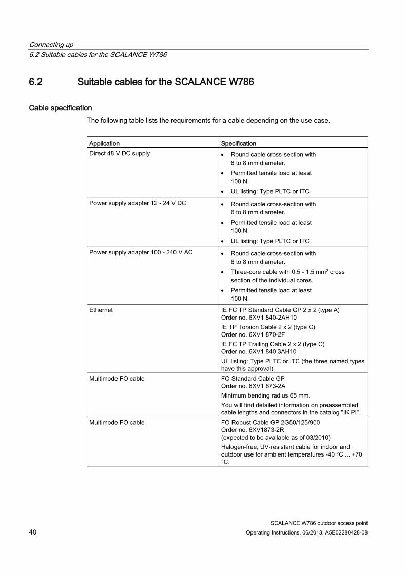
Cable specification The following table lists the requirements for a cable depending on the use case.
Application Specification Direct 48 V DC supply • Round cable cross-section with
6 to 8 mm diameter. • Permitted tensile load at least
100 N. • UL listing: Type PLTC or ITC
Power supply adapter 12 - 24 V DC • Round cable cross-section with 6 to 8 mm diameter.
• Permitted tensile load at least 100 N.
• UL listing: Type PLTC or ITC
Power supply adapter 100 - 240 V AC • Round cable cross-section with 6 to 8 mm diameter.
• Three-core cable with 0.5 - 1.5 mm2 cross section of the individual cores.
• Permitted tensile load at least 100 N.
Ethernet IE FC TP Standard Cable GP 2 x 2 (type A) Order no. 6XV1 840-2AH10 IE TP Torsion Cable 2 x 2 (type C) Order no. 6XV1 870-2F IE FC TP Trailing Cable 2 x 2 (type C) Order no. 6XV1 840 3AH10 UL listing: Type PLTC or ITC (the three named types have this approval)
Multimode FO cable FO Standard Cable GP Order no. 6XV1 873-2A Minimum bending radius 65 mm. You will find detailed information on preassembled cable lengths and connectors in the catalog "IK PI".
Multimode FO cable FO Robust Cable GP 2G50/125/900 Order no. 6XV1873-2R (expected to be available as of 03/2010) Halogen-free, UV-resistant cable for indoor and outdoor use for ambient temperatures -40 °C ... +70 °C.
Connecting up 6.2 Suitable cables for the SCALANCE W786
SCALANCE W786 outdoor access point Operating Instructions, 06/2013, A5E02280428-08 41
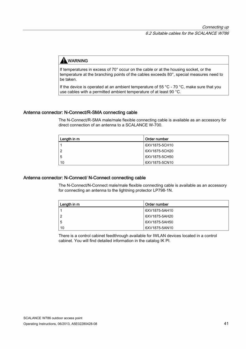
WARNING
If temperatures in excess of 70° occur on the cable or at the housing socket, or the temperature at the branching points of the cables exceeds 80°, special measures need to be taken.
If the device is operated at an ambient temperature of 55 °C - 70 °C, make sure that you use cables with a permitted ambient temperature of at least 90 °C.
Antenna connector: N-Connect/R-SMA connecting cable The N-Connect/R-SMA male/male flexible connecting cable is available as an accessory for direct connection of an antenna to a SCALANCE W-700.
Length in m Order number 1 2 5 10
6XV1875-5CH10 6XV1875-5CH20 6XV1875-5CH50 6XV1875-5CN10
Antenna connector: N-Connect/ N-Connect connecting cable The N-Connect/N-Connect male/male flexible connecting cable is available as an accessory for connecting an antenna to the lightning protector LP798-1N.
Length in m Order number 1 2 5 10
6XV1875-5AH10 6XV1875-5AH20 6XV1875-5AH50 6XV1875-5AN10
There is a control cabinet feedthrough available for IWLAN devices located in a control cabinet. You will find detailed information in the catalog IK PI.
Connecting up 6.3 Connecting the cables
SCALANCE W786 outdoor access point 42 Operating Instructions, 06/2013, A5E02280428-08
6.3 Connecting the cables
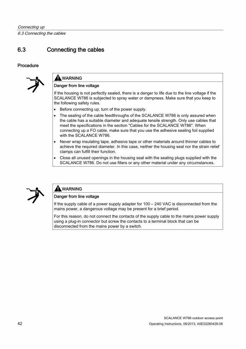
Procedure
WARNING
Danger from line voltage
If the housing is not perfectly sealed, there is a danger to life due to the line voltage if the SCALANCE W786 is subjected to spray water or dampness. Make sure that you keep to the following safety rules. • Before connecting up, turn of the power supply. • The sealing of the cable feedthroughs of the SCALANCE W786 is only assured when
the cable has a suitable diameter and adequate tensile strength. Only use cables that meet the specifications in the section "Cables for the SCALANCE W786". When connecting up a FO cable, make sure that you use the adhesive sealing foil supplied with the SCALANCE W786.
• Never wrap insulating tape, adhesive tape or other materials around thinner cables to achieve the required diameter. In this case, neither the housing seal nor the strain relief clamps can fulfill their function.
• Close all unused openings in the housing seal with the sealing plugs supplied with the SCALANCE W786. Do not use fillers or any other material under any circumstances.
WARNING
Danger from line voltage
If the supply cable of a power supply adapter for 100 – 240 VAC is disconnected from the mains power, a dangerous voltage may be present for a brief period.
For this reason, do not connect the contacts of the supply cable to the mains power supply using a plug-in connector but screw the contacts to a terminal block that can be disconnected from the mains power by a switch.
Connecting up 6.3 Connecting the cables
SCALANCE W786 outdoor access point Operating Instructions, 06/2013, A5E02280428-08 43
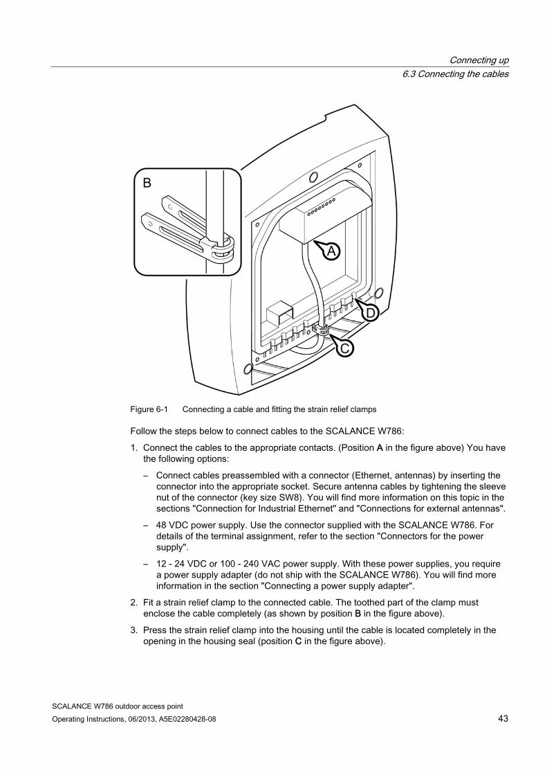
Figure 6-1 Connecting a cable and fitting the strain relief clamps
Follow the steps below to connect cables to the SCALANCE W786:
1. Connect the cables to the appropriate contacts. (Position A in the figure above) You have the following options:
– Connect cables preassembled with a connector (Ethernet, antennas) by inserting the connector into the appropriate socket. Secure antenna cables by tightening the sleeve nut of the connector (key size SW8). You will find more information on this topic in the sections "Connection for Industrial Ethernet" and "Connections for external antennas".
– 48 VDC power supply. Use the connector supplied with the SCALANCE W786. For details of the terminal assignment, refer to the section "Connectors for the power supply".
– 12 - 24 VDC or 100 - 240 VAC power supply. With these power supplies, you require a power supply adapter (do not ship with the SCALANCE W786). You will find more information in the section "Connecting a power supply adapter".
2. Fit a strain relief clamp to the connected cable. The toothed part of the clamp must enclose the cable completely (as shown by position B in the figure above).
3. Press the strain relief clamp into the housing until the cable is located completely in the opening in the housing seal (position C in the figure above).
Connecting up 6.3 Connecting the cables
SCALANCE W786 outdoor access point 44 Operating Instructions, 06/2013, A5E02280428-08
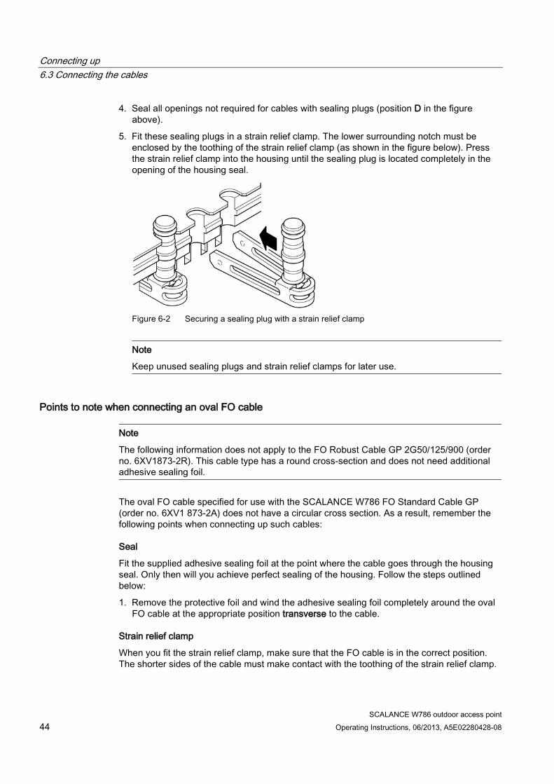
4. Seal all openings not required for cables with sealing plugs (position D in the figure above).
5. Fit these sealing plugs in a strain relief clamp. The lower surrounding notch must be enclosed by the toothing of the strain relief clamp (as shown in the figure below). Press the strain relief clamp into the housing until the sealing plug is located completely in the opening of the housing seal.
Figure 6-2 Securing a sealing plug with a strain relief clamp
Note
Keep unused sealing plugs and strain relief clamps for later use.
Points to note when connecting an oval FO cable
Note
The following information does not apply to the FO Robust Cable GP 2G50/125/900 (order no. 6XV1873-2R). This cable type has a round cross-section and does not need additional adhesive sealing foil.
The oval FO cable specified for use with the SCALANCE W786 FO Standard Cable GP (order no. 6XV1 873-2A) does not have a circular cross section. As a result, remember the following points when connecting up such cables:
Seal
Fit the supplied adhesive sealing foil at the point where the cable goes through the housing seal. Only then will you achieve perfect sealing of the housing. Follow the steps outlined below:
1. Remove the protective foil and wind the adhesive sealing foil completely around the oval FO cable at the appropriate position transverse to the cable.
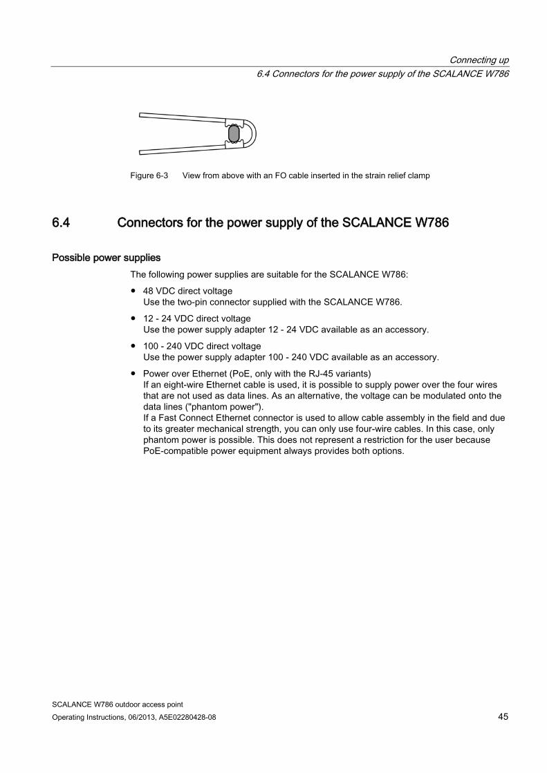
Strain relief clamp
When you fit the strain relief clamp, make sure that the FO cable is in the correct position. The shorter sides of the cable must make contact with the toothing of the strain relief clamp.
Connecting up 6.4 Connectors for the power supply of the SCALANCE W786
SCALANCE W786 outdoor access point Operating Instructions, 06/2013, A5E02280428-08 45
Figure 6-3 View from above with an FO cable inserted in the strain relief clamp
6.4 Connectors for the power supply of the SCALANCE W786
Possible power supplies The following power supplies are suitable for the SCALANCE W786:
● 48 VDC direct voltage Use the two-pin connector supplied with the SCALANCE W786.
● 12 - 24 VDC direct voltage Use the power supply adapter 12 - 24 VDC available as an accessory.
● 100 - 240 VDC direct voltage Use the power supply adapter 100 - 240 VDC available as an accessory.
● Power over Ethernet (PoE, only with the RJ-45 variants) If an eight-wire Ethernet cable is used, it is possible to supply power over the four wires that are not used as data lines. As an alternative, the voltage can be modulated onto the data lines ("phantom power"). If a Fast Connect Ethernet connector is used to allow cable assembly in the field and due to its greater mechanical strength, you can only use four-wire cables. In this case, only phantom power is possible. This does not represent a restriction for the user because PoE-compatible power equipment always provides both options.
Connecting up 6.4 Connectors for the power supply of the SCALANCE W786
SCALANCE W786 outdoor access point 46 Operating Instructions, 06/2013, A5E02280428-08
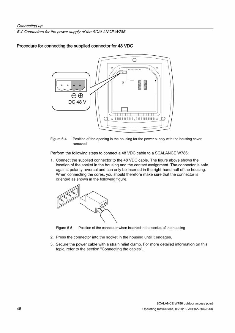
Procedure for connecting the supplied connector for 48 VDC
Figure 6-4 Position of the opening in the housing for the power supply with the housing cover
removed
Perform the following steps to connect a 48 VDC cable to a SCALANCE W786:
1. Connect the supplied connector to the 48 VDC cable. The figure above shows the location of the socket in the housing and the contact assignment. The connector is safe against polarity reversal and can only be inserted in the right-hand half of the housing. When connecting the cores, you should therefore make sure that the connector is oriented as shown in the following figure.
Figure 6-5 Position of the connector when inserted in the socket of the housing
2. Press the connector into the socket in the housing until it engages.
3. Secure the power cable with a strain relief clamp. For more detailed information on this topic, refer to the section "Connecting the cables".
Connecting up 6.5 Connecting a power supply adapter
SCALANCE W786 outdoor access point Operating Instructions, 06/2013, A5E02280428-08 47
6.5 Connecting a power supply adapter
Input voltage options The optional power supply adapter is available in two versions:
● Power supply adapter for 12 - 24 V DC direct voltage
● Power supply adapter for 100 - 240 V AC alternating voltage
Note
Applies only to SCALANCE W786-3xx
If a SCALANCE W786-3xx is operated with diversity for three antenna pairs, the power for 12 - 24 V DC cannot be supplied redundantly. In this case, there is no further opening in the housing for a second power cable.
How to fit the power supply adapter
WARNING
Danger from line voltage
Only electrical specialists may open the device and connect the power supply adapter!
Connect or disconnect power supply cables only when the power is turned off!
Start the SCALANCE W786 only when you have screwed down the housing cover again so that there is once again protection against touching live parts!

Connecting up 6.5 Connecting a power supply adapter
SCALANCE W786 outdoor access point 48 Operating Instructions, 06/2013, A5E02280428-08
NOTICE
Exceeding the EMC limit values • SCALANCE W786 with RJ-45 interface with DC power supply adapter or without power
supply adapter
When using a SCALANCE W786 with RJ-45 connector without a power supply adapter or with a DC power adapter, no additional measures are necessary for use in a residential environment. • SCALANCE W786 with RJ-45 interface with AC power supply adapter PS791-2AC
When using a SCALANCE W786 with a power supply adapter PS791-2AC (100-240 V AC), the requirements for use in an industrial environment are met without any additional measures being necessary.
When used in a residential environment, noise produced by this configuration can be reduced by fitting an EMC ferrite (a snap ferrite) to the power supply cable as close as possible to the power supply adapter. You can order suitable ferrites from the following company:
Würth Elektronik eiSos GmbH & Co. KG Max-Eyth-Strasse 1 – 3 D-74638 Waldenburg, Germany
Model designation: STAR-TEC with safety key technology cable diameter 6 – 7.5 mm: Order no. 74271131 cable diameter 7 – 8.5 mm: Order no. 74271132 • SCALANCE W786 with fiber-optic interface
The SCALANCE W786 devices with a fiber-optic interface generally only meet the emission limit values for use in an industrial environment.
If you use the power supply adapter PS791-2AC (100 -240 V AC voltage) in a domestic area (EMV class B), fit an EMC ferrite (a snap ferrite) to the supply cable as close as possible to the power supply adapter. This measure is unnecessary in an industrial environment.
Connecting up 6.5 Connecting a power supply adapter
SCALANCE W786 outdoor access point Operating Instructions, 06/2013, A5E02280428-08 49
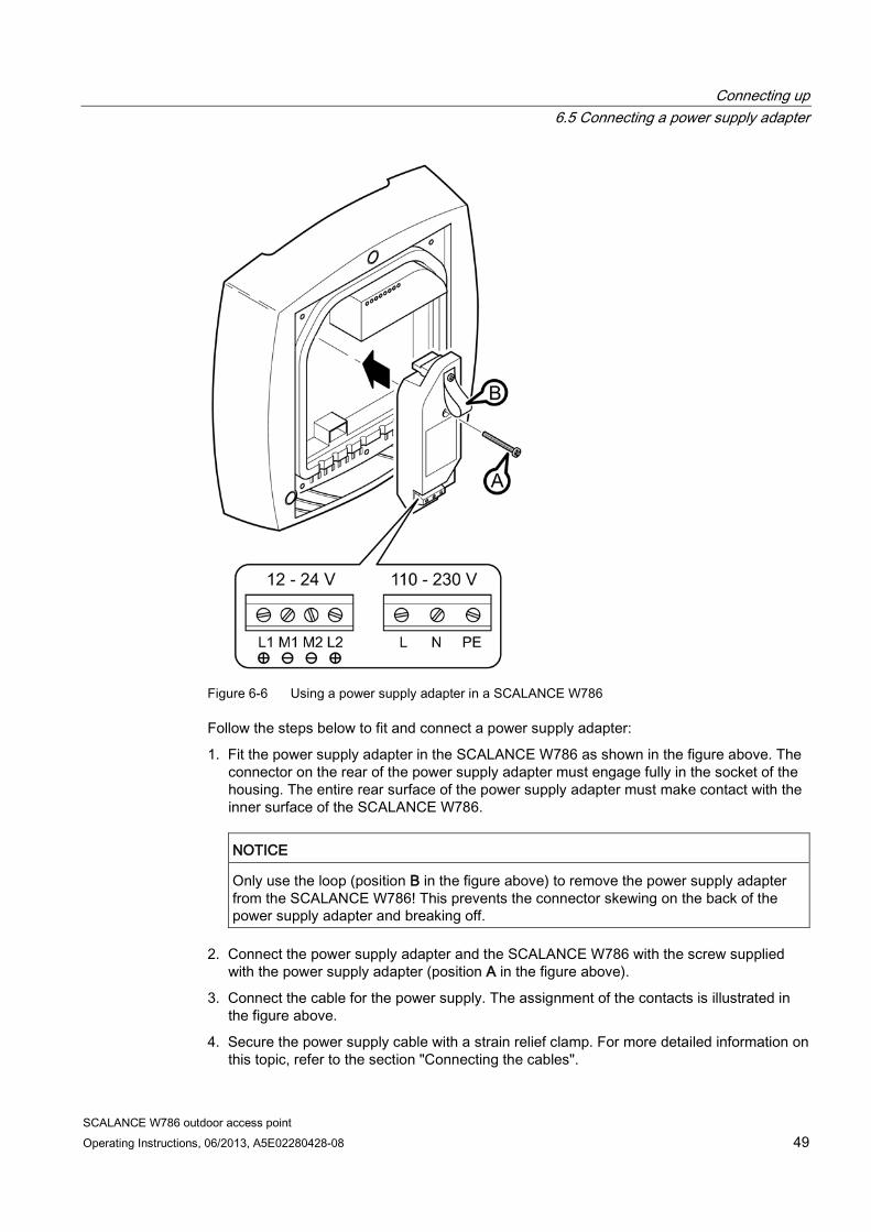
Figure 6-6 Using a power supply adapter in a SCALANCE W786
Follow the steps below to fit and connect a power supply adapter:
1. Fit the power supply adapter in the SCALANCE W786 as shown in the figure above. The connector on the rear of the power supply adapter must engage fully in the socket of the housing. The entire rear surface of the power supply adapter must make contact with the inner surface of the SCALANCE W786.
NOTICE
Only use the loop (position B in the figure above) to remove the power supply adapter from the SCALANCE W786! This prevents the connector skewing on the back of the power supply adapter and breaking off.
2. Connect the power supply adapter and the SCALANCE W786 with the screw supplied with the power supply adapter (position A in the figure above).
3. Connect the cable for the power supply. The assignment of the contacts is illustrated in the figure above.
4. Secure the power supply cable with a strain relief clamp. For more detailed information on this topic, refer to the section "Connecting the cables".
Connecting up 6.5 Connecting a power supply adapter
SCALANCE W786 outdoor access point 50 Operating Instructions, 06/2013, A5E02280428-08
The following applies to the PS791-2AC (AC 100 – 240 V) only:
WARNING
Danger from line voltage
The strain relief clamp may damage the insulation under unfavorable circumstances. You run the risk of encountering danger from line voltage through the strain relief clamp.
For a line with 100 to 240 VAC use an insulated strain relief clamp only; it is included in the scope of delivery for the power supply adapter!
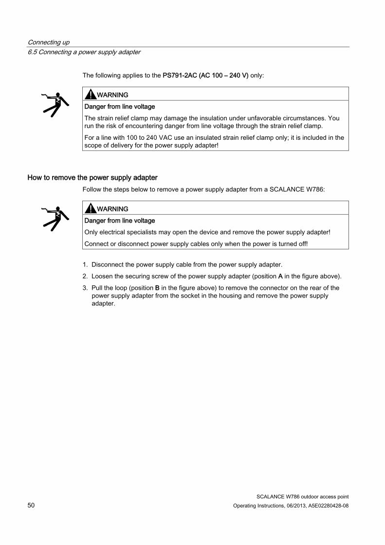
How to remove the power supply adapter Follow the steps below to remove a power supply adapter from a SCALANCE W786:
WARNING
Danger from line voltage
Only electrical specialists may open the device and remove the power supply adapter!
Connect or disconnect power supply cables only when the power is turned off!
1. Disconnect the power supply cable from the power supply adapter.
2. Loosen the securing screw of the power supply adapter (position A in the figure above).
3. Pull the loop (position B in the figure above) to remove the connector on the rear of the power supply adapter from the socket in the housing and remove the power supply adapter.
Connecting up 6.6 Connection for Industrial Ethernet
SCALANCE W786 outdoor access point Operating Instructions, 06/2013, A5E02280428-08 51
6.6 Connection for Industrial Ethernet
Device variants With a SCALANCE W786, you have the choice of two Ethernet ports:
● RJ-45 jack
● ST duplex socket for multimode FO cables 1310 nm and a maximum cable length of 3000 m
Procedure for connecting an Ethernet cable
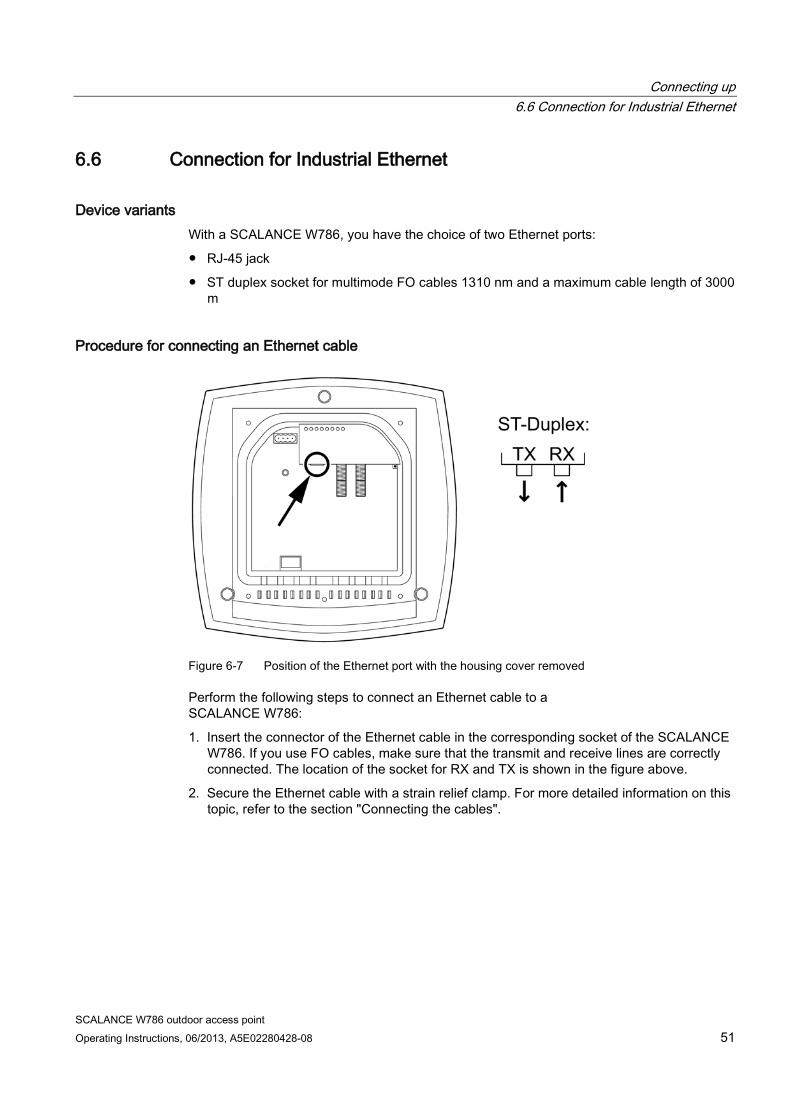
Figure 6-7 Position of the Ethernet port with the housing cover removed
Perform the following steps to connect an Ethernet cable to a SCALANCE W786:
1. Insert the connector of the Ethernet cable in the corresponding socket of the SCALANCE W786. If you use FO cables, make sure that the transmit and receive lines are correctly connected. The location of the socket for RX and TX is shown in the figure above.
2. Secure the Ethernet cable with a strain relief clamp. For more detailed information on this topic, refer to the section "Connecting the cables".
Connecting up 6.7 Connectors for external antennas
SCALANCE W786 outdoor access point 52 Operating Instructions, 06/2013, A5E02280428-08
6.7 Connectors for external antennas
How to connect external antennas
Note
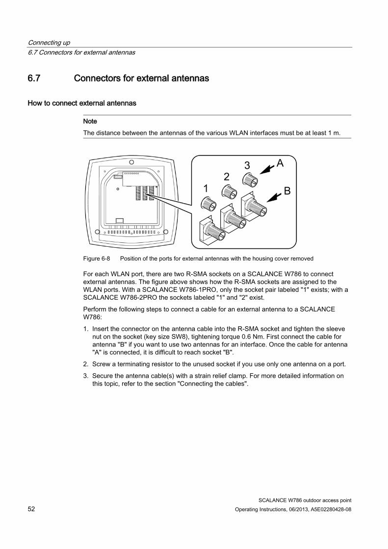
The distance between the antennas of the various WLAN interfaces must be at least 1 m.
Figure 6-8 Position of the ports for external antennas with the housing cover removed
For each WLAN port, there are two R-SMA sockets on a SCALANCE W786 to connect external antennas. The figure above shows how the R-SMA sockets are assigned to the WLAN ports. With a SCALANCE W786-1PRO, only the socket pair labeled "1" exists; with a SCALANCE W786-2PRO the sockets labeled "1" and "2" exist.
Perform the following steps to connect a cable for an external antenna to a SCALANCE W786:
1. Insert the connector on the antenna cable into the R-SMA socket and tighten the sleeve nut on the socket (key size SW8), tightening torque 0.6 Nm. First connect the cable for antenna "B" if you want to use two antennas for an interface. Once the cable for antenna "A" is connected, it is difficult to reach socket "B".
2. Screw a terminating resistor to the unused socket if you use only one antenna on a port.
3. Secure the antenna cable(s) with a strain relief clamp. For more detailed information on this topic, refer to the section "Connecting the cables".
Connecting up 6.8 Inserting / removing the C-PLUG
SCALANCE W786 outdoor access point Operating Instructions, 06/2013, A5E02280428-08 53
6.8 Inserting / removing the C-PLUG
WARNING
Danger from line voltage
Once you have removed the housing cover, there is the danger from line voltage in the area of the connecting terminals on the power supply adapter.
Only authorized personnel is permitted to open the device and carry out any work on the open device (e.g. connection and disconnection of lines, operating the reset button, replacing the C-PLUG).
NOTICE
A C-PLUG may only be inserted or removed when the device is turned off.
Inserting the C-PLUG
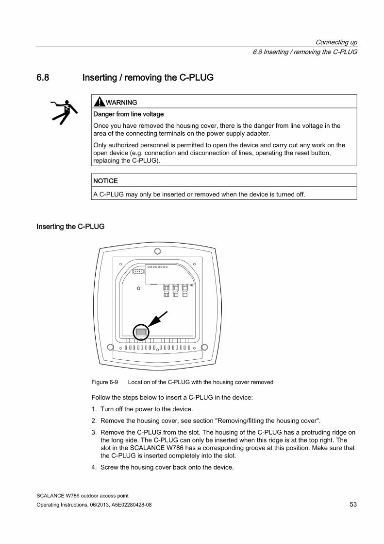
Figure 6-9 Location of the C-PLUG with the housing cover removed
Follow the steps below to insert a C-PLUG in the device:
1. Turn off the power to the device.
2. Remove the housing cover, see section "Removing/fitting the housing cover".
3. Remove the C-PLUG from the slot. The housing of the C-PLUG has a protruding ridge on the long side. The C-PLUG can only be inserted when this ridge is at the top right. The slot in the SCALANCE W786 has a corresponding groove at this position. Make sure that the C-PLUG is inserted completely into the slot.
4. Screw the housing cover back onto the device.
Connecting up 6.8 Inserting / removing the C-PLUG
SCALANCE W786 outdoor access point 54 Operating Instructions, 06/2013, A5E02280428-08
Removing the C-PLUG Follow the steps below to remove a C-PLUG from the device:
1. Turn off the power to the device.
2. Remove the housing cover, see section "Removing/fitting the housing cover".
3. Insert a screwdriver between the front edge of the C-PLUG and the slot and release the C-PLUG.
4. Remove the C-PLUG from the slot.
5. Screw the housing cover back onto the device.
SCALANCE W786 outdoor access point Operating Instructions, 06/2013, A5E02280428-08 55
Technical specifications 7 7.1 SCALANCE W786 technical specifications
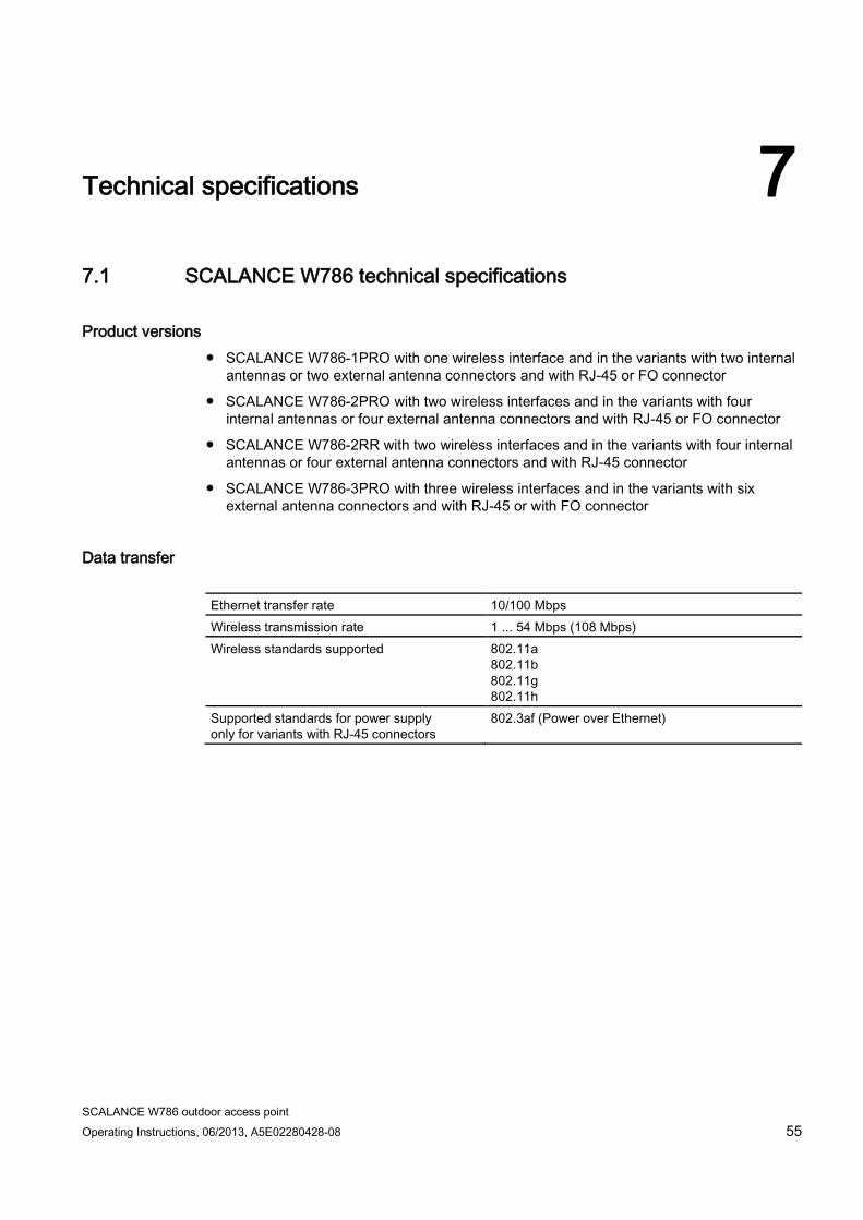
Product versions ● SCALANCE W786-1PRO with one wireless interface and in the variants with two internal
antennas or two external antenna connectors and with RJ-45 or FO connector
● SCALANCE W786-2PRO with two wireless interfaces and in the variants with four internal antennas or four external antenna connectors and with RJ-45 or FO connector
● SCALANCE W786-2RR with two wireless interfaces and in the variants with four internal antennas or four external antenna connectors and with RJ-45 connector
● SCALANCE W786-3PRO with three wireless interfaces and in the variants with six external antenna connectors and with RJ-45 or with FO connector
Data transfer Ethernet transfer rate 10/100 Mbps Wireless transmission rate 1 ... 54 Mbps (108 Mbps) Wireless standards supported
802.11a 802.11b 802.11g 802.11h
Supported standards for power supply only for variants with RJ-45 connectors
802.3af (Power over Ethernet)
Technical specifications 7.1 SCALANCE W786 technical specifications
SCALANCE W786 outdoor access point 56 Operating Instructions, 06/2013, A5E02280428-08
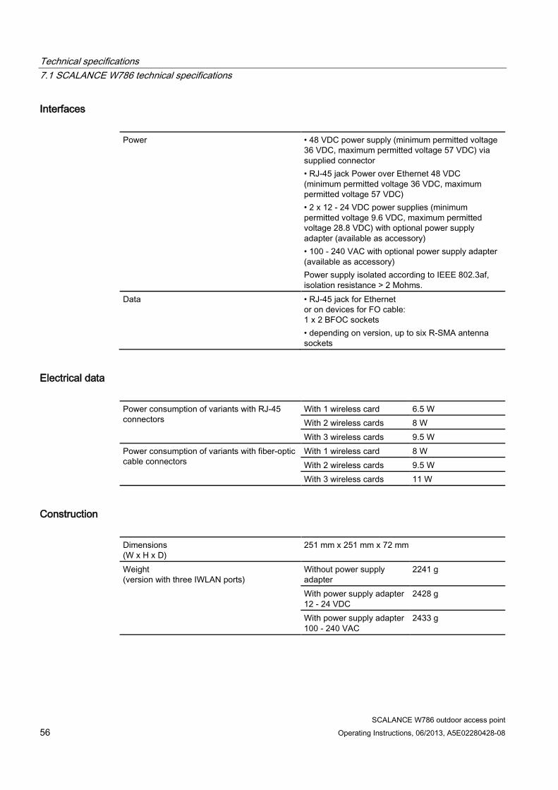
Interfaces Power • 48 VDC power supply (minimum permitted voltage
36 VDC, maximum permitted voltage 57 VDC) via supplied connector • RJ-45 jack Power over Ethernet 48 VDC (minimum permitted voltage 36 VDC, maximum permitted voltage 57 VDC) • 2 x 12 - 24 VDC power supplies (minimum permitted voltage 9.6 VDC, maximum permitted voltage 28.8 VDC) with optional power supply adapter (available as accessory) • 100 - 240 VAC with optional power supply adapter (available as accessory) Power supply isolated according to IEEE 802.3af, isolation resistance > 2 Mohms.
Data • RJ-45 jack for Ethernet or on devices for FO cable: 1 x 2 BFOC sockets • depending on version, up to six R-SMA antenna sockets
Electrical data Power consumption of variants with RJ-45 connectors
With 1 wireless card 6.5 W With 2 wireless cards 8 W With 3 wireless cards 9.5 W
Power consumption of variants with fiber-optic cable connectors
With 1 wireless card 8 W With 2 wireless cards 9.5 W With 3 wireless cards 11 W
Construction Dimensions (W x H x D)
251 mm x 251 mm x 72 mm
Weight (version with three IWLAN ports)
Without power supply adapter
2241 g
With power supply adapter 12 - 24 VDC
2428 g
With power supply adapter 100 - 240 VAC
2433 g
Technical specifications 7.1 SCALANCE W786 technical specifications
SCALANCE W786 outdoor access point Operating Instructions, 06/2013, A5E02280428-08 57
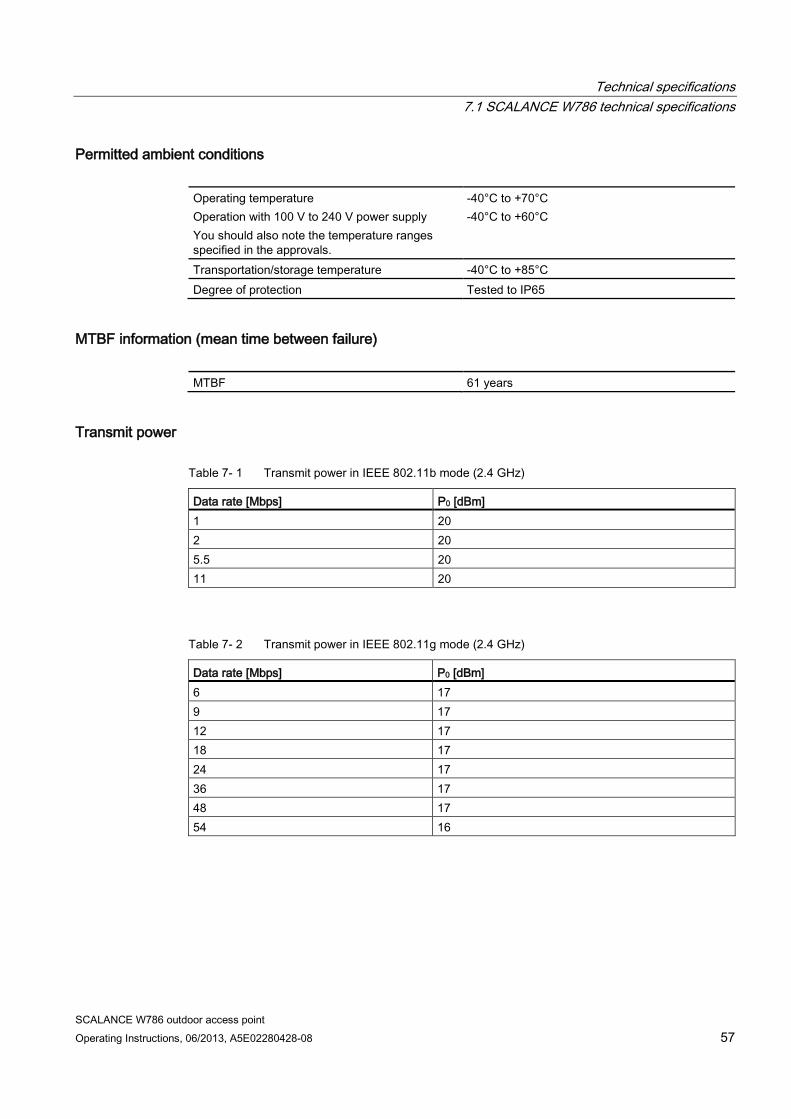
Permitted ambient conditions Operating temperature Operation with 100 V to 240 V power supply You should also note the temperature ranges specified in the approvals.
-40°C to +70°C -40°C to +60°C
Transportation/storage temperature -40°C to +85°C Degree of protection Tested to IP65
MTBF information (mean time between failure) MTBF 61 years
Transmit power
Table 7- 1 Transmit power in IEEE 802.11b mode (2.4 GHz)
Data rate [Mbps] P0 [dBm] 1 20 2 20 5.5 20 11 20
Table 7- 2 Transmit power in IEEE 802.11g mode (2.4 GHz)
Data rate [Mbps] P0 [dBm] 6 17 9 17 12 17 18 17 24 17 36 17 48 17 54 16
Technical specifications 7.1 SCALANCE W786 technical specifications
SCALANCE W786 outdoor access point 58 Operating Instructions, 06/2013, A5E02280428-08
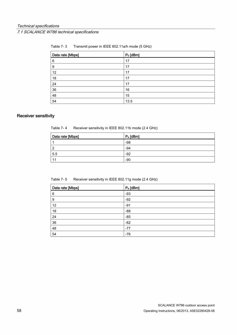
Table 7- 3 Transmit power in IEEE 802.11a/h mode (5 GHz)
Data rate [Mbps] P0 [dBm] 6 17 9 17 12 17 18 17 24 17 36 16 48 15 54 13.5
Receiver sensitivity
Table 7- 4 Receiver sensitivity in IEEE 802.11b mode (2.4 GHz)
Data rate [Mbps] Pe [dBm] 1 -98 2 -94 5.5 -92 11 -90
Table 7- 5 Receiver sensitivity in IEEE 802.11g mode (2.4 GHz)
Data rate [Mbps] Pe [dBm] 6 -93 9 -92 12 -91 18 -88 24 -85 36 -82 48 -77 54 -76
Technical specifications 7.2 Dimension drawing SCALANCE W786
SCALANCE W786 outdoor access point Operating Instructions, 06/2013, A5E02280428-08 59
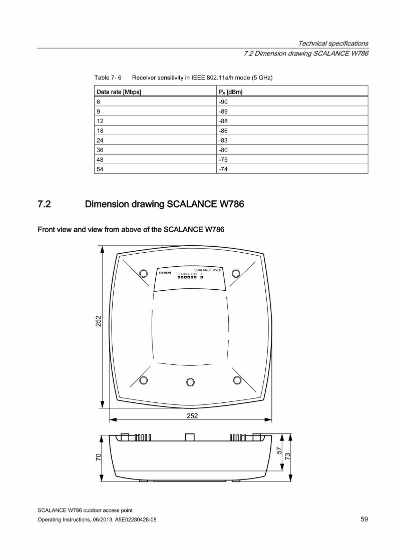
Table 7- 6 Receiver sensitivity in IEEE 802.11a/h mode (5 GHz)
Data rate [Mbps] Pe [dBm] 6 -90 9 -89 12 -88 18 -86 24 -83 36 -80 48 -75 54 -74
7.2 Dimension drawing SCALANCE W786
Front view and view from above of the SCALANCE W786
Technical specifications 7.3 Permitted antennas
SCALANCE W786 outdoor access point 60 Operating Instructions, 06/2013, A5E02280428-08
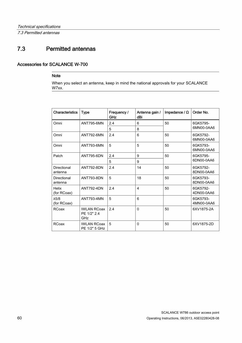
7.3 Permitted antennas
Accessories for SCALANCE W-700
Note
When you select an antenna, keep in mind the national approvals for your SCALANCE W7xx.
Characteristics Type Frequency /
GHz Antenna gain / dBi
Impedance / Ω Order No.
Omni ANT795-6MN 2.4 6 50 6GK5795-6MN00-0AA6 5 8
Omni ANT792-6MN 2.4 6 50 6GK5792-6MN00-0AA6
Omni ANT793-6MN 5 5 50 6GK5793-6MN00-0AA6
Patch ANT795-6DN 2.4 9 50 6GK5795-6DN00-0AA6 5 9
Directional antenna
ANT792-8DN 2.4 14 50 6GK5792-8DN00-0AA6
Directional antenna
ANT793-8DN 5 18 50 6GK5793-8DN00-0AA6
Helix (for RCoax)
ANT792-4DN 2.4 4 50 6GK5792-4DN00-0AA6
λ5/8 (for RCoax)
ANT793-4MN 5 6 6GK5793-4MN00-0AA6
RCoax IWLAN RCoax PE 1/2" 2.4 GHz
2.4 0 50 6XV1875-2A
RCoax IWLAN RCoax PE 1/2" 5 GHz
5 0 50 6XV1875-2D
Technical specifications 7.4 Radiation patterns diagrams of SCALANCE W786 internal antennas
SCALANCE W786 outdoor access point Operating Instructions, 06/2013, A5E02280428-08 61
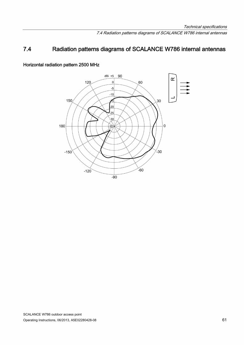
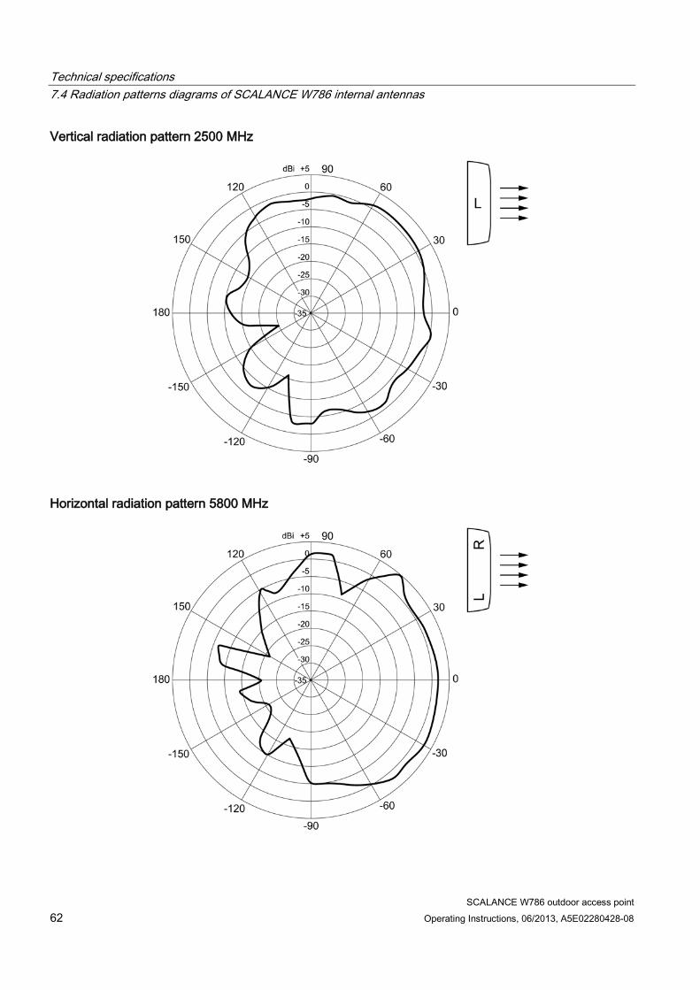
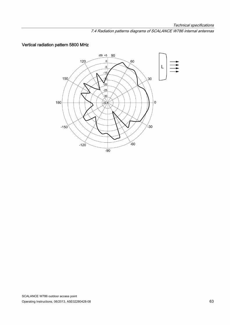
7.4 Radiation patterns diagrams of SCALANCE W786 internal antennas
Horizontal radiation pattern 2500 MHz
Technical specifications 7.4 Radiation patterns diagrams of SCALANCE W786 internal antennas
SCALANCE W786 outdoor access point 62 Operating Instructions, 06/2013, A5E02280428-08
Vertical radiation pattern 2500 MHz
Horizontal radiation pattern 5800 MHz
Technical specifications 7.4 Radiation patterns diagrams of SCALANCE W786 internal antennas
SCALANCE W786 outdoor access point Operating Instructions, 06/2013, A5E02280428-08 63
Vertical radiation pattern 5800 MHz

Technical specifications 7.4 Radiation patterns diagrams of SCALANCE W786 internal antennas
SCALANCE W786 outdoor access point 64 Operating Instructions, 06/2013, A5E02280428-08
SCALANCE W786 outdoor access point Operating Instructions, 06/2013, A5E02280428-08 65
Certification 8 8.1 Approvals for SCALANCE W786
CE conformity The products
SIMATIC NET SCALANCE W786-1PRO SIMATIC NET SCALANCE W786-2PRO SIMATIC NET SCALANCE W786-3PRO SIMATIC NET SCALANCE W786-2RR in the version put into circulation by Siemens AG meet the regulations of the following European directives:
● 99/5/EC Directive of the European Parliament and of the Council on radio equipment and telecommunications terminal equipment and the mutual recognition of their conformity. Conformity with the basic requirement of the directive is attested by adherence to the following standards:
● EN 60950-1 Information technology equipment - Safety - Part 1: General requirements
● EN 301489-1 V1.9.2 Electromagnetic compatibility and radio spectrum matters (ERM) - Electromagnetic compatibility for radio equipment and services - Part 1 : Common technical requirements (V1.9.2).
● EN 301489-17 V2.2.1 Electromagnetic compatibility and radio spectrum matters (ERM) - Electromagnetic compatibility for radio equipment and services - Part 17: Specific conditions for 2.4 GHz broadband transmission systems and 5 GHz high performance RLAN equipment
● EN 300328 V1.7.1 Electromagnetic Compatibility and Radio Spectrum Matters (ERM); — Broadband transmission systems — Data transmission equipment operating in the 2.4 GHz ISM band and using spread spectrum modulation techniques — Harmonized EN covering essential requirements under article 3.2 of the R&TTE Directive
● EN 301893 V1.7.1 Broadband Radio Access Networks (BRAN) - 5 GHz high performance RLAN - Harmonized EN covering essential requirements of article 3.2 of the R&TTE Directive
Certification 8.1 Approvals for SCALANCE W786
SCALANCE W786 outdoor access point 66 Operating Instructions, 06/2013, A5E02280428-08
● EN 50385 Product standard to demonstrate the compliance of radio base stations and fixed terminal stations for wireless telecommunication systems with the basic restrictions or the reference levels related to human exposure to radio frequency electromagnetic fields (110 MHz - 40 GHz) - General public
● 1999/519/EC Council recommendation on the limitation of exposure of the general public to electromagnetic fields (0 Hz to 300 GHz)
Devices connected to the system must meet the relevant safety regulations.
The EC Declaration of Conformity is available for the responsible authorities according to the above-mentioned EC Directive at the following address:
Siemens Aktiengesellschaft Industry Sector Postfach 4848 D-90026 Nürnberg
This declaration certifies compliance with the directives named above, but does not guarantee any specific properties.
Note
The specified approvals apply only when the corresponding mark is printed on the product.
Certification 8.1 Approvals for SCALANCE W786
SCALANCE W786 outdoor access point Operating Instructions, 06/2013, A5E02280428-08 67
ATEX, FM and cULus approvals The products
SCALANCE W786-1PRO SCALANCE W786-2PRO SCALANCE W786-3PRO SCALANCE W786-2RR
have the following approvals
● EN 60079-15 : 2005 EN 60079-0 : 2006 II 3 G Ex nA II T4 KEMA 07 ATEX 0145 X Ta: -40 °C to +60 ℃
● FM 3611 CL. 1, Div. 2 GP.A.B.C.D T4 CL. 1, Zone 2, GP.IIC. T4 Ta: -40 °C ... +70 ℃ 100 V ... 240 V Ta: -40 °C to +60 ℃
● c-UL-us UL 60950-1, CSA C22.2 No. 60950-1 Ta: -40 °C ... 70℃ 100 V ... 240 V Ta: -40 °C to +60 ℃
● c-UL-us for hazardous location: UL 1604, CSA C22.2 No. 213-M1987 CL. 1, Div. 2 GP. A.B.C.D T4 CL. 1, Zone 2, GP, IIC, T4 Ta : -40°C … 70°C 100 V ... 240 V Ta: -40 °C to +60 ℃
Note
The specified approvals apply only when the corresponding mark is printed on the product.
NEMA 4X The products
SCALANCE W786-1PRO SCALANCE W786-2PRO SCALANCE W786-3PRO SCALANCE W786-2RR
have the following approval
● NEMA 250 : 2003
Other approvals The products
Certification 8.1 Approvals for SCALANCE W786
SCALANCE W786 outdoor access point 68 Operating Instructions, 06/2013, A5E02280428-08
SCALANCE W786-1PRO SCALANCE W786-2PRO SCALANCE W786-3PRO SCALANCE W786-2RR
meet the stipulations of the following directives or standards:
● Directive 72/245/EC, last changed by directive 2006/28/EC Type approval number e1*72/245*2006/28*5311*00 E1: Number of approval 025311
Note
The requirements are met only when the device is screwed to a mounting plate and a cover plate for the cabling. For detailed information, refer to the section "Mounting with mounting plate".
Certification 8.1 Approvals for SCALANCE W786
SCALANCE W786 outdoor access point Operating Instructions, 06/2013, A5E02280428-08 69
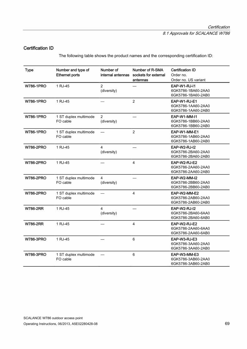
Certification ID The following table shows the product names and the corresponding certification ID:
Type Number and type of Ethernet ports
Number of internal antennas
Number of R-SMA sockets for external antennas
Certification ID Order no. Order no. US variant
W786-1PRO 1 RJ-45 2 (diversity)
— EAP-W1-RJ-I1 6GK5786-1BA60-2AA0 6GK5786-1BA60-2AB0
W786-1PRO 1 RJ-45 — 2 EAP-W1-RJ-E1 6GK5786-1AA60-2AA0 6GK5786-1AA60-2AB0
W786-1PRO 1 ST duplex multimode FO cable
2 (diversity)
— EAP-W1-MM-I1 6GK5786-1BB60-2AA0 6GK5786-1BB60-2AB0
W786-1PRO 1 ST duplex multimode FO cable
— 2 EAP-W1-MM-E1 6GK5786-1AB60-2AA0 6GK5786-1AB60-2AB0
W786-2PRO 1 RJ-45 4 (diversity)
— EAP-W2-RJ-I2 6GK5786-2BA60-2AA0 6GK5786-2BA60-2AB0
W786-2PRO 1 RJ-45 — 4 EAP-W2-RJ-E2 6GK5786-2AA60-2AA0 6GK5786-2AA60-2AB0
W786-2PRO 1 ST duplex multimode FO cable
4 (diversity)
— EAP-W2-MM-I2 6GK5786-2BB60-2AA0 6GK5786-2BB60-2AB0
W786-2PRO 1 ST duplex multimode FO cable
— 4 EAP-W2-MM-E2 6GK5786-2AB60-2AA0 6GK5786-2AB60-2AB0
W786-2RR 1 RJ-45 4 (diversity)
— EAP-W2-RJ-I2 6GK5786-2BA60-6AA0 6GK5786-2BA60-6AB0
W786-2RR 1 RJ-45 — 4 EAP-W2-RJ-E2 6GK5786-2AA60-6AA0 6GK5786-2AA60-6AB0
W786-3PRO 1 RJ-45 — 6 EAP-W3-RJ-E3 6GK5786-3AA60-2AA0 6GK5786-3AA60-2AB0
W786-3PRO 1 ST duplex multimode FO cable
— 6 EAP-W3-MM-E3 6GK5786-3AB60-2AA0 6GK5786-3AB60-2AB0
Certification 8.1 Approvals for SCALANCE W786
SCALANCE W786 outdoor access point 70 Operating Instructions, 06/2013, A5E02280428-08
Certification 8.1 Approvals for SCALANCE W786
SCALANCE W786 outdoor access point Operating Instructions, 06/2013, A5E02280428-08 71
FCC approval This device complies with Part 15 of the FCC Rules
Operation is subject to the following two conditions:
(1) this device may not cause harmful interference, and (2) this device must accept any interference received, including interference that may cause undesired operation.
IEEE802.11b or g operation of this product in the USA is firmware-limited to channels 1 through11.
___________________________________________________________________________
Notice
Changes or modifications made to this equipment not expressly approved by SIEMENS may void the FCC authorization to operate this equipment. ___________________________________________________________________________
This equipment has been tested and found to comply with the limits for a Class B digital device, pursuant to Part 15 of the FCC Rules. These limits are designed to provide reasonable protection against harmful interference in a residential installation. This equipment generates, uses and can radiate radio frequency energy and, if not installed and used in accordance with the instructions, may cause harmful interference to radio communications. However, there is no guarantee that interference will not occur in a particular installation. If this equipment does cause harmful interference to radio or television reception, which can be determined by turning the equipment off and on, the user is encouraged to try to correct the interference by one or more of the following measures:
● Reorient or relocate the receiving antenna.
● Increase the separation between the equipment and receiver.
● Connect the equipment into an outlet on a circuit different from that to which the receiver is connected.
● Consult the dealer or an experienced radio/TV technician for help.
___________________________________________________________________________
Notice
This equipment complies with FCC radiation exposure limits set forth for an uncontrolled environment. This equipment should be installed and operated with minimum distance 20 cm between the radiator and your body.
___________________________________________________________________________
This transmitter must not be co-located or operating in conjunction with any other antenna or transmitter.
Professional Installation Notice:

Certification 8.1 Approvals for SCALANCE W786
SCALANCE W786 outdoor access point 72 Operating Instructions, 06/2013, A5E02280428-08
To comply with FCC part 15 rules in the United States, the system must be professionally installed to ensure compliance with the Part 15 certification. It is the responsibility of the operator and professional installer to ensure that only certified systems are deployed in the United States. The use of the system in any other combination (such as co-located antennas transmitting the same information) is expressly forbidden.
Note
In the USA, the "ANT793-8DN" antenna is approved only for wireless mode 802.11a!
Note
The specified approvals apply only when the corresponding mark is printed on the product.
RSS-210 of Industry Canada "Operation is subject to the following two conditions: (1) this device may not cause interference, and (2) this device must accept any interference, including interference that may cause undesired operation of the device."
"This device has been designed to operate with the antennas listed below*, and having a maximum gain of 18 dBi. Antennas not included in this list or having a gain greater than 18 dBi are strictly prohibited for use with this device. The required antenna impedance is 50 ohms."
"To reduce potential radio interference to other users, the antenna type and its gain should be so chosen that the equivalent isotropically radiated power (e.i.r.p.) is not more than that permitted for successful communication."
"That the device for the band 5150-5250 MHz is only for indoor usage to reduce potential for harmful interference to co-channel mobile satellite systems."
"Users should also be cautioned to take note that high power radars are allocated as primary users (meaning they have priority) of 5250-5350 MHz and 5650-5850 MHz and these radars could cause interference and/or damage to LE-LAN devices."
* For more detailed information on the approved antennas, refer to the section "Technical specifications".
Note
In Canada, the "ANT793-8DN" antenna is approved only for wireless mode 802.11a!
Note
The specified approvals apply only when the corresponding mark is printed on the product.
Certification 8.1 Approvals for SCALANCE W786
SCALANCE W786 outdoor access point Operating Instructions, 06/2013, A5E02280428-08 73
NCC Warning Statement (Taiwan) Article 12 Without permission, any company, firm or user shall not alter the frequency, increase the power, or change the characteristics and functions of the original design of the certified lower power frequency electric machinery.
Article 14 The application of low power frequency electric machineries shall not affect the navigation safety nor interfere a legal communication, if an interference is found, the service will be suspended until improvement is made and the interference no longer exists.
Note
The "ANT793-8DN" antenna is not approved in Taiwan!
Note
The specified approvals apply only when the corresponding mark is printed on the product.
KCC Statement (Republic of Korea) 사용자안내문(제5조제1항제1호관련)
기 종 별 사 용 자 안 내 문 A 급 기기 (업무용 방송통신기기)
이 기기는 업무용(A 급)으로 전자파적합등록을 한 기기이오니 판매자 또는 사용자는 이 점을 주의하시기 바라며, 가정외의 지역에서 사용하는 것을 목적으로 합니다.
"당해 무선설비는 전파혼신 가능성이 있으므로 인명안전과 관련된 서비스는 할 수 없음"
Note
The specified approvals apply only when the corresponding mark is printed on the product.
Notes on approval in Mexico
Certification ID Certification number EAP-W1-RJ-E1 RCPSIEA08-0713 EAP-W1-RJ-I1 RCPSIEA08-0713-A1 EAP-W1-MM-E1 RCPSIEA08-0713-A5 EAP-W1-MM-I1 RCPSIEA08-0713-A6
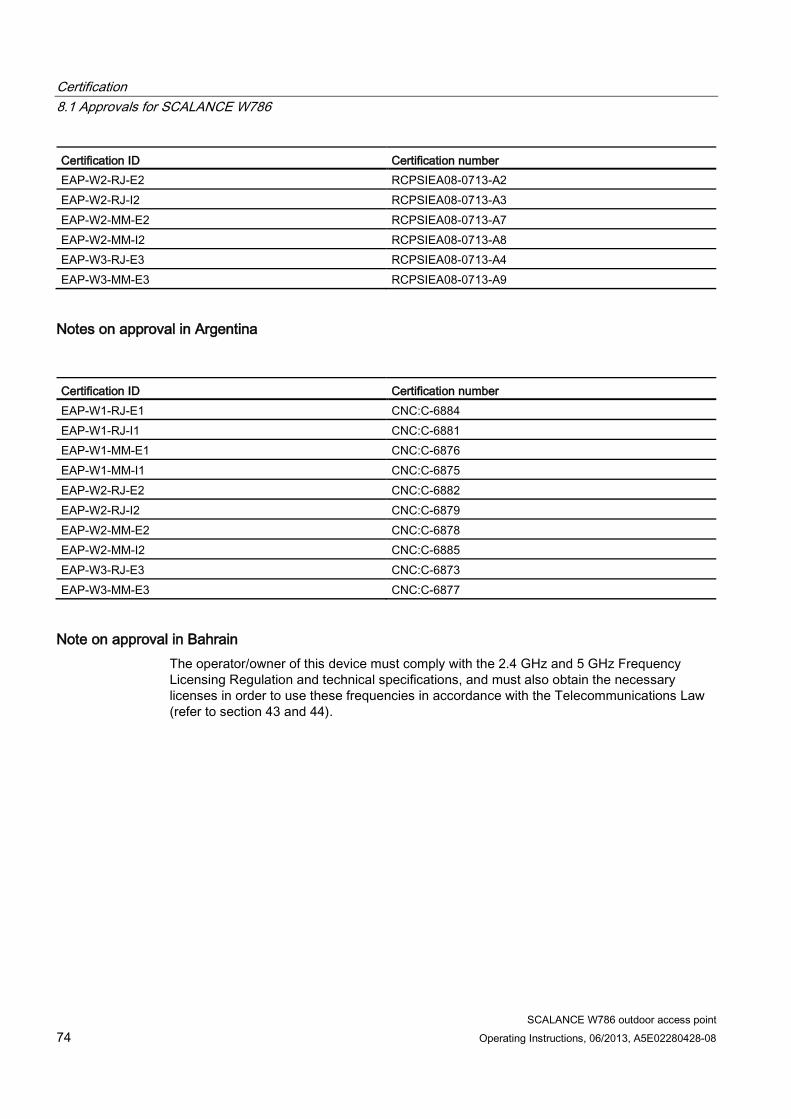
Certification 8.1 Approvals for SCALANCE W786
SCALANCE W786 outdoor access point 74 Operating Instructions, 06/2013, A5E02280428-08
Certification ID Certification number EAP-W2-RJ-E2 RCPSIEA08-0713-A2 EAP-W2-RJ-I2 RCPSIEA08-0713-A3 EAP-W2-MM-E2 RCPSIEA08-0713-A7 EAP-W2-MM-I2 RCPSIEA08-0713-A8 EAP-W3-RJ-E3 RCPSIEA08-0713-A4 EAP-W3-MM-E3 RCPSIEA08-0713-A9
Notes on approval in Argentina
Certification ID Certification number EAP-W1-RJ-E1 CNC:C-6884 EAP-W1-RJ-I1 CNC:C-6881 EAP-W1-MM-E1 CNC:C-6876 EAP-W1-MM-I1 CNC:C-6875 EAP-W2-RJ-E2 CNC:C-6882 EAP-W2-RJ-I2 CNC:C-6879 EAP-W2-MM-E2 CNC:C-6878 EAP-W2-MM-I2 CNC:C-6885 EAP-W3-RJ-E3 CNC:C-6873 EAP-W3-MM-E3 CNC:C-6877
Note on approval in Bahrain The operator/owner of this device must comply with the 2.4 GHz and 5 GHz Frequency Licensing Regulation and technical specifications, and must also obtain the necessary licenses in order to use these frequencies in accordance with the Telecommunications Law (refer to section 43 and 44).
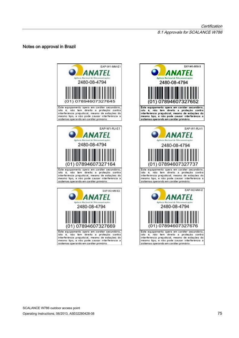
Certification 8.1 Approvals for SCALANCE W786
SCALANCE W786 outdoor access point Operating Instructions, 06/2013, A5E02280428-08 75
Notes on approval in Brazil
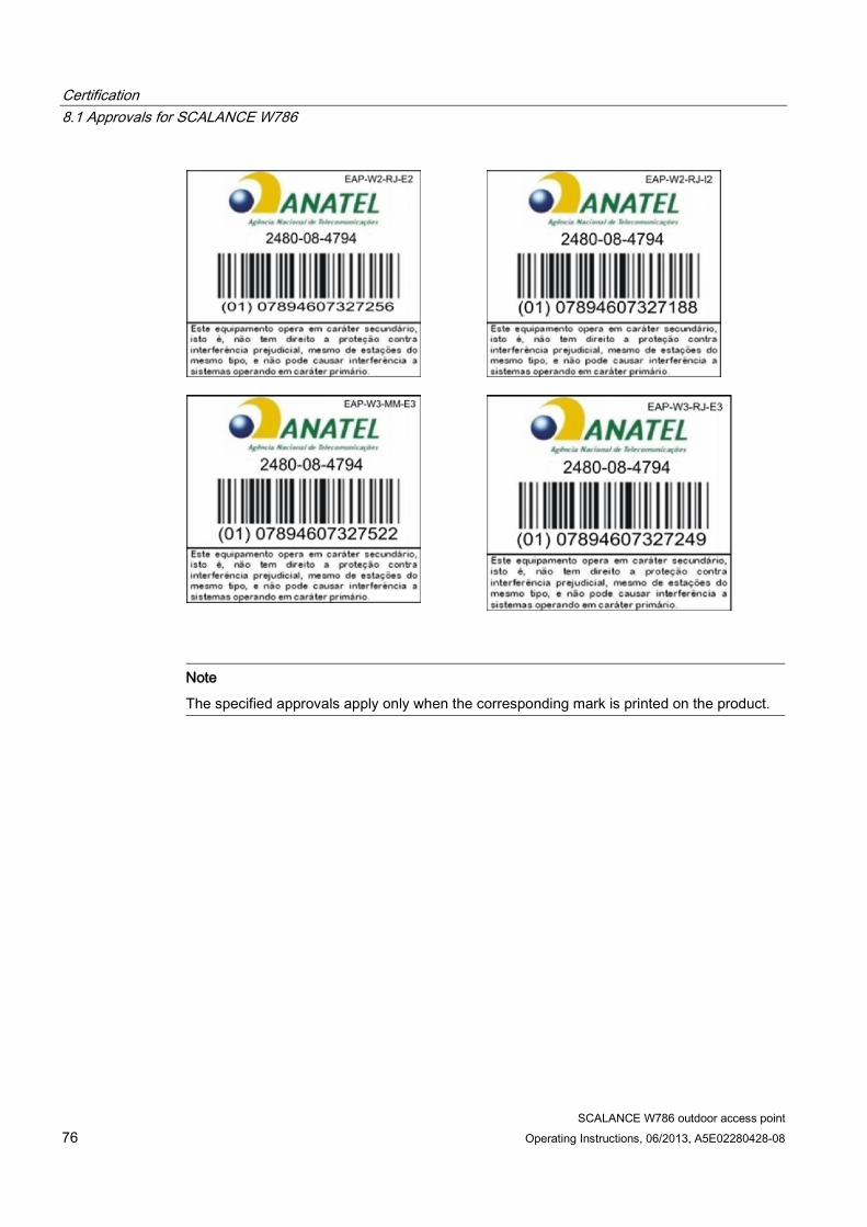
Certification 8.1 Approvals for SCALANCE W786
SCALANCE W786 outdoor access point 76 Operating Instructions, 06/2013, A5E02280428-08
Note
The specified approvals apply only when the corresponding mark is printed on the product.
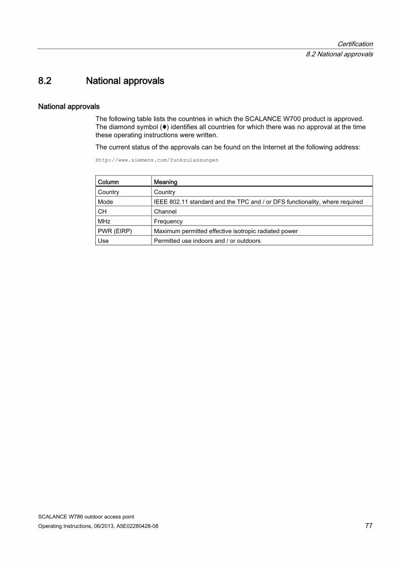
Certification 8.2 National approvals
SCALANCE W786 outdoor access point Operating Instructions, 06/2013, A5E02280428-08 77
8.2 National approvals
National approvals The following table lists the countries in which the SCALANCE W700 product is approved. The diamond symbol (♦) identifies all countries for which there was no approval at the time these operating instructions were written.
The current status of the approvals can be found on the Internet at the following address:
Http://www.siemens.com/funkzulassungen
Column Meaning Country Country Mode IEEE 802.11 standard and the TPC and / or DFS functionality, where required CH Channel MHz Frequency PWR (EIRP) Maximum permitted effective isotropic radiated power Use Permitted use indoors and / or outdoors
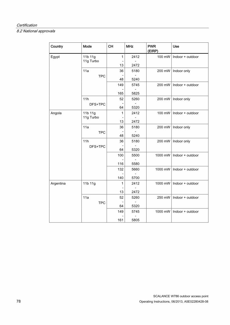
Certification 8.2 National approvals
SCALANCE W786 outdoor access point 78 Operating Instructions, 06/2013, A5E02280428-08
Country Mode CH MHz PWR (EIRP)
Use
Egypt 11b 11g 11g Turbo
1 -
13
2412 -
2472
100 mW Indoor + outdoor
11a TPC
36 -
48
5180 -
5240
200 mW Indoor only
149 -
165
5745 -
5825
200 mW Indoor + outdoor
11h DFS+TPC
52 -
64
5260 -
5320
200 mW Indoor only
Angola 11b 11g 11g Turbo
1 -
13
2412 -
2472
100 mW Indoor + outdoor
11a TPC
36 -
48
5180 -
5240
200 mW Indoor only
11h DFS+TPC
36 -
64
5180 -
5320
200 mW Indoor only
100 -
116
5500 -
5580
1000 mW Indoor + outdoor
132 -
140
5660 -
5700
1000 mW Indoor + outdoor
Argentina 11b 11g 1 -
13
2412 -
2472
1000 mW Indoor + outdoor
11a TPC
52 -
64
5260 -
5320
250 mW Indoor + outdoor
149 -
161
5745 -
5805
1000 mW Indoor + outdoor
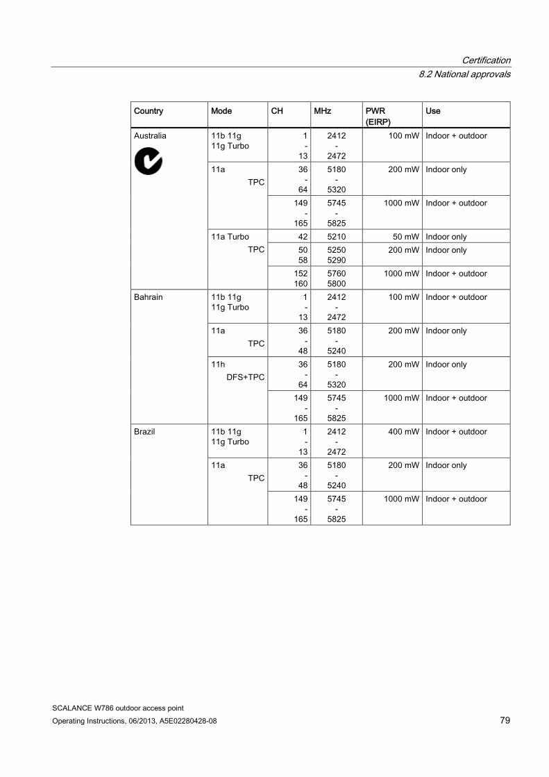
Certification 8.2 National approvals
SCALANCE W786 outdoor access point Operating Instructions, 06/2013, A5E02280428-08 79
Country Mode CH MHz PWR (EIRP)
Use
Australia
11b 11g 11g Turbo
1 -
13
2412 -
2472
100 mW Indoor + outdoor
11a TPC
36 -
64
5180 -
5320
200 mW Indoor only
149 -
165
5745 -
5825
1000 mW Indoor + outdoor
11a Turbo TPC
42 5210 50 mW Indoor only 50 58
5250 5290
200 mW Indoor only
152 160
5760 5800
1000 mW Indoor + outdoor
Bahrain 11b 11g 11g Turbo
1 -
13
2412 -
2472
100 mW Indoor + outdoor
11a TPC
36 -
48
5180 -
5240
200 mW Indoor only
11h DFS+TPC
36 -
64
5180 -
5320
200 mW Indoor only
149 -
165
5745 -
5825
1000 mW Indoor + outdoor
Brazil 11b 11g 11g Turbo
1 -
13
2412 -
2472
400 mW Indoor + outdoor
11a TPC
36 -
48
5180 -
5240
200 mW Indoor only
149 -
165
5745 -
5825
1000 mW Indoor + outdoor
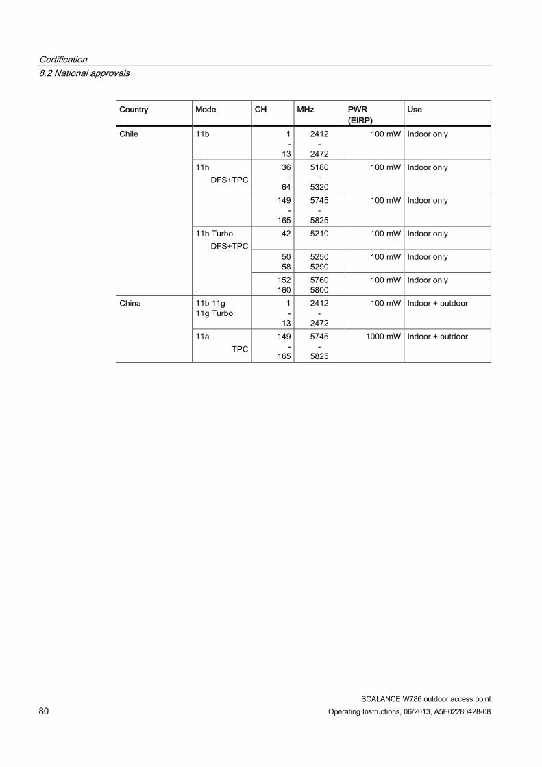
Certification 8.2 National approvals
SCALANCE W786 outdoor access point 80 Operating Instructions, 06/2013, A5E02280428-08
Country Mode CH MHz PWR (EIRP)
Use
Chile 11b 1 -
13
2412 -
2472
100 mW Indoor only
11h DFS+TPC
36 -
64
5180 -
5320
100 mW Indoor only
149 -
165
5745 -
5825
100 mW Indoor only
11h Turbo DFS+TPC
42
5210
100 mW Indoor only
50 58
5250 5290
100 mW Indoor only
152 160
5760 5800
100 mW Indoor only
China 11b 11g 11g Turbo
1 -
13
2412 -
2472
100 mW Indoor + outdoor
11a TPC
149 -
165
5745 -
5825
1000 mW Indoor + outdoor
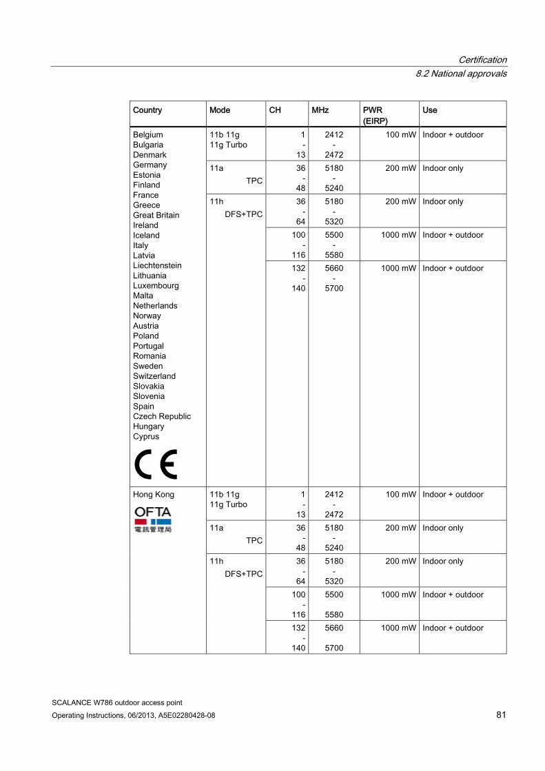
Certification 8.2 National approvals
SCALANCE W786 outdoor access point Operating Instructions, 06/2013, A5E02280428-08 81
Country Mode CH MHz PWR (EIRP)
Use
Belgium Bulgaria Denmark Germany Estonia Finland France Greece Great Britain Ireland Iceland Italy Latvia Liechtenstein Lithuania Luxembourg Malta Netherlands Norway Austria Poland Portugal Romania Sweden Switzerland Slovakia Slovenia Spain Czech Republic Hungary Cyprus
11b 11g 11g Turbo
1 -
13
2412 -
2472
100 mW Indoor + outdoor
11a TPC
36 -
48
5180 -
5240
200 mW Indoor only
11h DFS+TPC
36 -
64
5180 -
5320
200 mW Indoor only
100 -
116
5500 -
5580
1000 mW Indoor + outdoor
132 -
140
5660 -
5700
1000 mW Indoor + outdoor
Hong Kong
11b 11g 11g Turbo
1 -
13
2412 -
2472
100 mW Indoor + outdoor
11a TPC
36 -
48
5180 -
5240
200 mW Indoor only
11h DFS+TPC
36 -
64
5180 -
5320
200 mW Indoor only
100 -
116
5500
5580
1000 mW Indoor + outdoor
132 -
140
5660
5700
1000 mW Indoor + outdoor
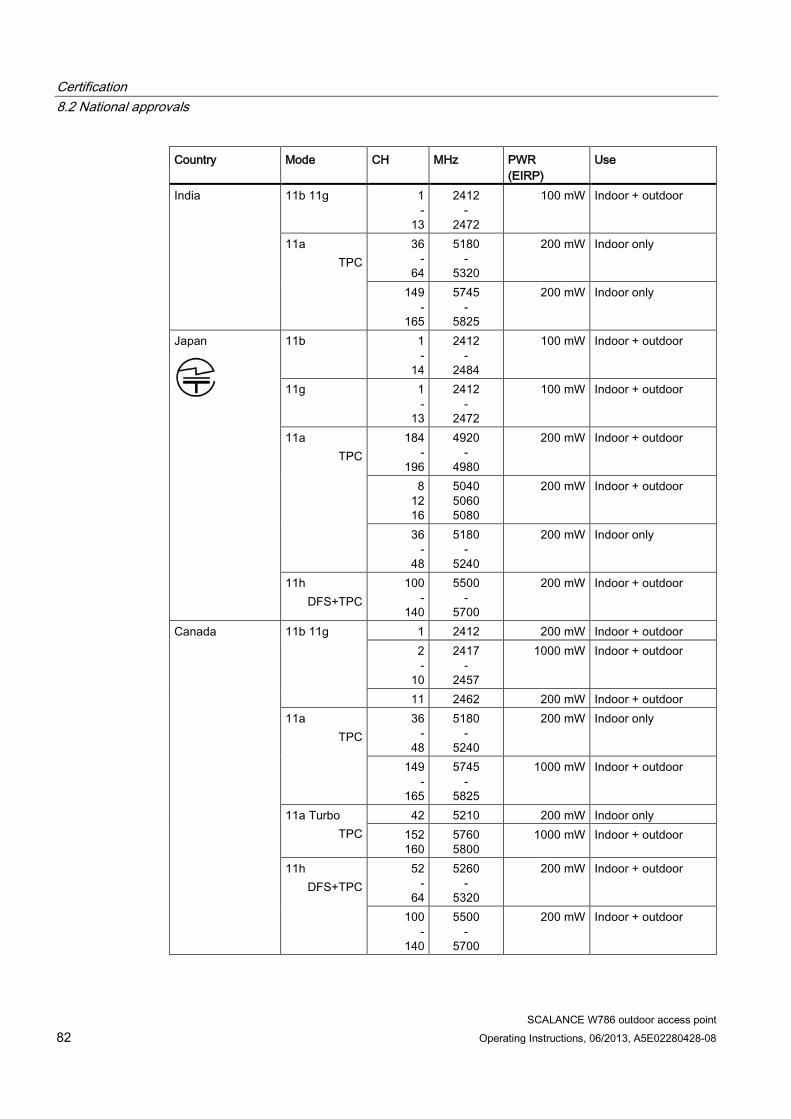
Certification 8.2 National approvals
SCALANCE W786 outdoor access point 82 Operating Instructions, 06/2013, A5E02280428-08
Country Mode CH MHz PWR (EIRP)
Use
India 11b 11g 1 -
13
2412 -
2472
100 mW Indoor + outdoor
11a TPC
36 -
64
5180 -
5320
200 mW Indoor only
149 -
165
5745 -
5825
200 mW Indoor only
Japan
11b 1 -
14
2412 -
2484
100 mW Indoor + outdoor
11g 1 -
13
2412 -
2472
100 mW Indoor + outdoor
11a TPC
184 -
196
4920 -
4980
200 mW Indoor + outdoor
8 12 16
5040 5060 5080
200 mW Indoor + outdoor
36 -
48
5180 -
5240
200 mW Indoor only
11h DFS+TPC
100 -
140
5500 -
5700
200 mW Indoor + outdoor
Canada 11b 11g 1 2412 200 mW Indoor + outdoor 2 -
10
2417 -
2457
1000 mW Indoor + outdoor
11 2462 200 mW Indoor + outdoor 11a
TPC 36
- 48
5180 -
5240
200 mW Indoor only
149 -
165
5745 -
5825
1000 mW Indoor + outdoor
11a Turbo TPC
42 5210 200 mW Indoor only 152 160
5760 5800
1000 mW Indoor + outdoor
11h DFS+TPC
52 -
64
5260 -
5320
200 mW Indoor + outdoor
100 -
140
5500 -
5700
200 mW Indoor + outdoor
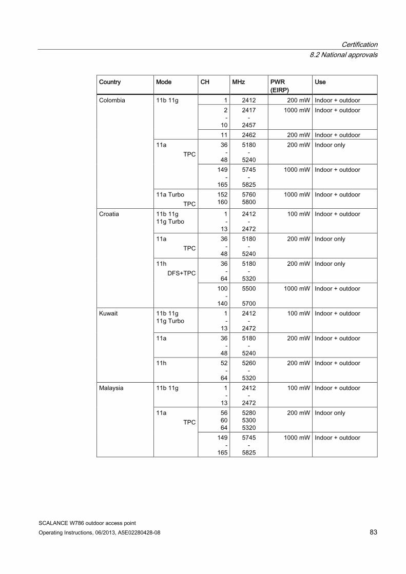
Certification 8.2 National approvals
SCALANCE W786 outdoor access point Operating Instructions, 06/2013, A5E02280428-08 83
Country Mode CH MHz PWR (EIRP)
Use
Colombia 11b 11g
1 2412 200 mW Indoor + outdoor 2 -
10
2417 -
2457
1000 mW Indoor + outdoor
11 2462 200 mW Indoor + outdoor 11a
TPC 36
- 48
5180 -
5240
200 mW Indoor only
149 -
165
5745 -
5825
1000 mW Indoor + outdoor
11a Turbo TPC
152 160
5760 5800
1000 mW Indoor + outdoor
Croatia 11b 11g 11g Turbo
1 -
13
2412 -
2472
100 mW Indoor + outdoor
11a TPC
36 -
48
5180 -
5240
200 mW Indoor only
11h DFS+TPC
36 -
64
5180 -
5320
200 mW Indoor only
100 -
140
5500
5700
1000 mW Indoor + outdoor
Kuwait 11b 11g 11g Turbo
1 -
13
2412 -
2472
100 mW Indoor + outdoor
11a 36 -
48
5180 -
5240
200 mW Indoor + outdoor
11h 52 -
64
5260 -
5320
200 mW Indoor + outdoor
Malaysia 11b 11g 1 -
13
2412 -
2472
100 mW Indoor + outdoor
11a TPC
56 60 64
5280 5300 5320
200 mW Indoor only
149 -
165
5745 -
5825
1000 mW Indoor + outdoor
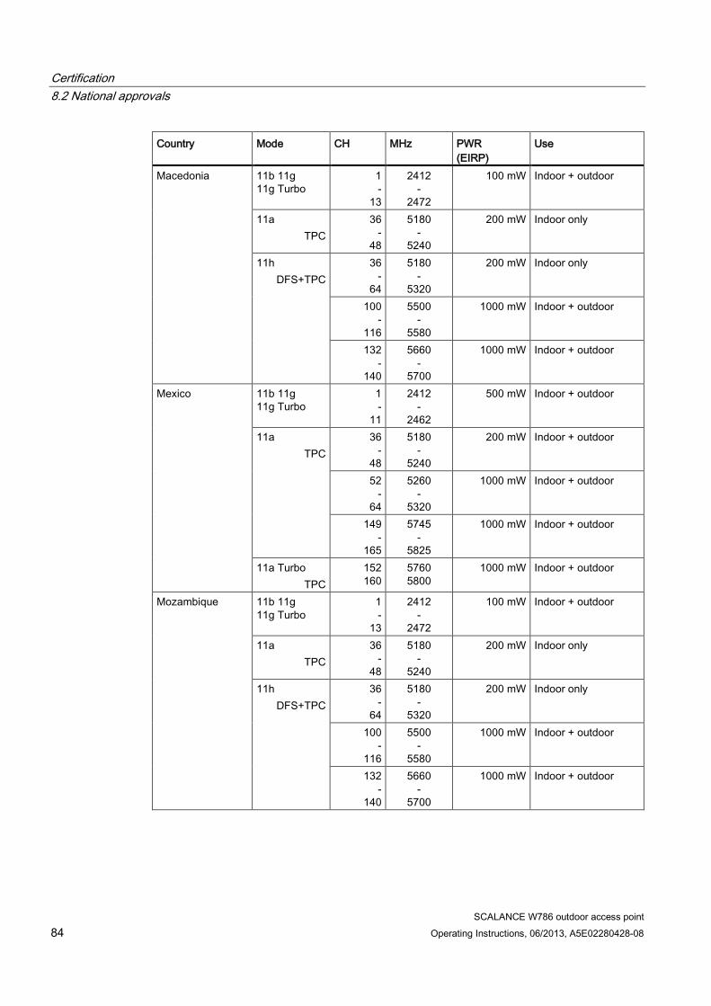
Certification 8.2 National approvals
SCALANCE W786 outdoor access point 84 Operating Instructions, 06/2013, A5E02280428-08
Country Mode CH MHz PWR (EIRP)
Use
Macedonia 11b 11g 11g Turbo
1 -
13
2412 -
2472
100 mW Indoor + outdoor
11a TPC
36 -
48
5180 -
5240
200 mW Indoor only
11h DFS+TPC
36 -
64
5180 -
5320
200 mW Indoor only
100 -
116
5500 -
5580
1000 mW Indoor + outdoor
132 -
140
5660 -
5700
1000 mW Indoor + outdoor
Mexico 11b 11g 11g Turbo
1 -
11
2412 -
2462
500 mW Indoor + outdoor
11a TPC
36 -
48
5180 -
5240
200 mW Indoor + outdoor
52 -
64
5260 -
5320
1000 mW Indoor + outdoor
149 -
165
5745 -
5825
1000 mW Indoor + outdoor
11a Turbo TPC
152 160
5760 5800
1000 mW Indoor + outdoor
Mozambique 11b 11g 11g Turbo
1 -
13
2412 -
2472
100 mW Indoor + outdoor
11a TPC
36 -
48
5180 -
5240
200 mW Indoor only
11h DFS+TPC
36 -
64
5180 -
5320
200 mW Indoor only
100 -
116
5500 -
5580
1000 mW Indoor + outdoor
132 -
140
5660 -
5700
1000 mW Indoor + outdoor
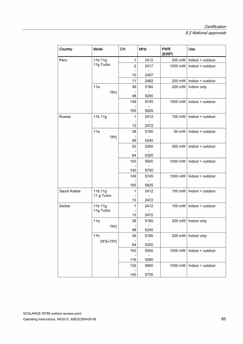
Certification 8.2 National approvals
SCALANCE W786 outdoor access point Operating Instructions, 06/2013, A5E02280428-08 85
Country Mode CH MHz PWR (EIRP)
Use
Peru 11b 11g 11g Turbo
1 2412 200 mW Indoor + outdoor 2 -
10
2417 -
2457
1000 mW Indoor + outdoor
11 2462 200 mW Indoor + outdoor 11a
TPC 36
- 48
5180 -
5240
200 mW Indoor only
149 -
165
5745 -
5825
1000 mW Indoor + outdoor
Russia 11b 11g 1 -
13
2412 -
2472
100 mW Indoor + outdoor
11a TPC
36 -
48
5180 -
5240
50 mW Indoor + outdoor
52 -
64
5260 -
5320
250 mW Indoor + outdoor
100 -
140
5500 -
5700
1000 mW Indoor + outdoor
149 -
165
5745 -
5825
1000 mW Indoor + outdoor
Saudi Arabia 11b 11g 11 g Turbo
1 -
13
2412 -
2472
100 mW Indoor + outdoor
Serbia 11b 11g 11g Turbo
1 -
13
2412 -
2472
100 mW Indoor + outdoor
11a TPC
36 -
48
5180 -
5240
200 mW Indoor only
11h DFS+TPC
36 -
64
5180 -
5320
200 mW Indoor only
100 -
116
5500 -
5580
1000 mW Indoor + outdoor
132 -
140
5660 -
5700
1000 mW Indoor + outdoor
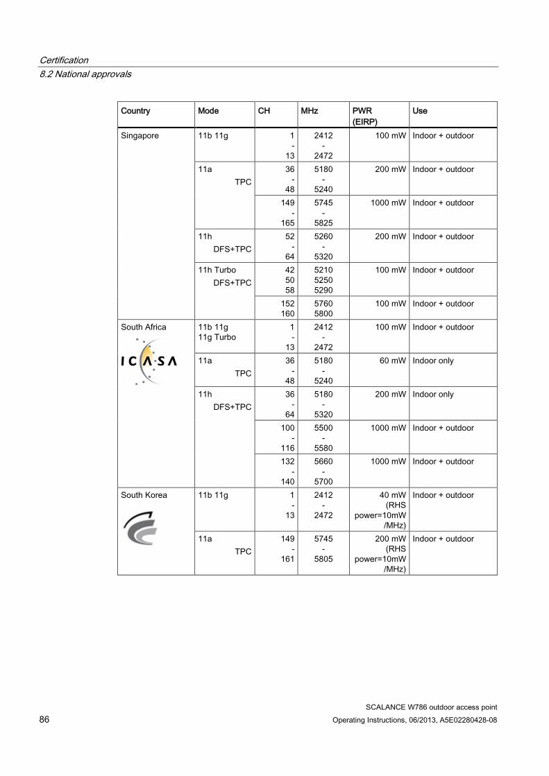
Certification 8.2 National approvals
SCALANCE W786 outdoor access point 86 Operating Instructions, 06/2013, A5E02280428-08
Country Mode CH MHz PWR (EIRP)
Use
Singapore 11b 11g
1 -
13
2412 -
2472
100 mW Indoor + outdoor
11a TPC
36 -
48
5180 -
5240
200 mW Indoor + outdoor
149 -
165
5745 -
5825
1000 mW Indoor + outdoor
11h DFS+TPC
52 -
64
5260 -
5320
200 mW Indoor + outdoor
11h Turbo DFS+TPC
42 50 58
5210 5250 5290
100 mW Indoor + outdoor
152 160
5760 5800
100 mW Indoor + outdoor
South Africa
11b 11g 11g Turbo
1 -
13
2412 -
2472
100 mW Indoor + outdoor
11a TPC
36 -
48
5180 -
5240
60 mW Indoor only
11h DFS+TPC
36 -
64
5180 -
5320
200 mW Indoor only
100 -
116
5500 -
5580
1000 mW Indoor + outdoor
132 -
140
5660 -
5700
1000 mW Indoor + outdoor
South Korea
11b 11g 1 -
13
2412 -
2472
40 mW (RHS
power=10mW/MHz)
Indoor + outdoor
11a TPC
149 -
161
5745 -
5805
200 mW (RHS
power=10mW/MHz)
Indoor + outdoor
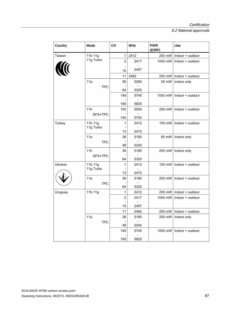
Certification 8.2 National approvals
SCALANCE W786 outdoor access point Operating Instructions, 06/2013, A5E02280428-08 87
Country Mode CH MHz PWR (EIRP)
Use
Taiwan
11b 11g 11g Turbo
1 2412 200 mW Indoor + outdoor 2 -
10
2417 -
2457
1000 mW Indoor + outdoor
11 2462 200 mW Indoor + outdoor 11a
TPC 56
- 64
5280 -
5320
50 mW Indoor only
149 -
165
5745 -
5825
1000 mW Indoor + outdoor
11h DFS+TPC
100 -
140
5500 -
5700
250 mW Indoor + outdoor
Turkey 11b 11g 11g Turbo
1 -
13
2412 -
2472
100 mW Indoor + outdoor
11a TPC
36 -
48
5180 -
5240
60 mW Indoor only
11h DFS+TPC
36 -
64
5180 -
5320
200 mW Indoor only
Ukraine
11b 11g 11g Turbo
1 -
13
2412 -
2472
100 mW Indoor + outdoor
11a TPC
36 -
64
5180 -
5320
200 mW Indoor + outdoor
Uruguay 11b 11g 1 2412 200 mW Indoor + outdoor 2 -
10
2417 -
2457
1000 mW Indoor + outdoor
11 2462 200 mW Indoor + outdoor 11a
TPC 36
- 48
5180 -
5240
200 mW Indoor only
149 -
165
5745 -
5825
1000 mW Indoor + outdoor

Certification 8.2 National approvals
SCALANCE W786 outdoor access point 88 Operating Instructions, 06/2013, A5E02280428-08
Country Mode CH MHz PWR (EIRP)
Use
United Arab Emirates
11b 11g 11g Turbo
1 -
13
2412 -
2472
100 mW Indoor + outdoor
11a TPC
36 -
48
5180 -
5240
200 mW Indoor only
11h DFS+TPC
36 -
64
5180 -
5320
200 mW Indoor only
100 -
116
5500 -
5580
1000 mW Indoor only
132 -
140
5660 -
5700
1000 mW Indoor only
Venezuela 11b 11g 11g Turbo
1 -
13
2412 -
2472
1000 mW Indoor + outdoor
11a TPC
36 -
64
5180 -
5320
200 mW Indoor only
149 -
165
5745 -
5825
200 mW Indoor + outdoor
11h 52 -
64
5260 -
5320
1000 mW Indoor + outdoor
United States of America
11b 11g 1 2412 200 mW Indoor + outdoor 2 -
10
2417 -
2457
1000 mW Indoor + outdoor
11 2462 200 mW Indoor + outdoor 11a
TPC 36
- 48
5180 -
5240
200 mW Indoor only
149 -
165
5745 -
5825
1000 mW Indoor + outdoor
11a Turbo TPC
152 160
5760 5800
1000 mW Indoor + outdoor
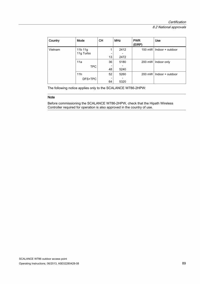
Certification 8.2 National approvals
SCALANCE W786 outdoor access point Operating Instructions, 06/2013, A5E02280428-08 89
Country Mode CH MHz PWR (EIRP)
Use
Vietnam 11b 11g 11g Turbo
1 -
13
2412 -
2472
100 mW Indoor + outdoor
11a TPC
36 -
48
5180 -
5240
200 mW Indoor only
11h DFS+TPC
52 -
64
5260 -
5320
200 mW Indoor + outdoor
The following notice applies only to the SCALANCE W786-2HPW:
Note
Before commissioning the SCALANCE W786-2HPW, check that the Hipath Wireless Controller required for operation is also approved in the country of use.

Certification 8.2 National approvals
SCALANCE W786 outdoor access point 90 Operating Instructions, 06/2013, A5E02280428-08