Embed Size (px)
Citation preview
SIMATIC NET
SCALANCE X204RNA SCALANCE X204RNA EEC (PRP) Operating Instructions
C79000-G8976-C294-03
Introduction 1
Safety notes 2
Network topologies and redundancy
3
Product characteristics 4
Installation 5
Connection 6
Functional description and configuration using Web based Management
7
Approvals and marking 8
Technical data 9
Accessories and compatible devices
10
References 11
Dimension drawings 12
Legal information Warning notice system
This manual contains notices you have to observe in order to ensure your personal safety, as well as to prevent damage to property. The notices referring to your personal safety are highlighted in the manual by a safety alert symbol, notices referring only to property damage have no safety alert symbol. These notices shown below are graded according to the degree of danger.
DANGER indicates that death or severe personal injury will result if proper precautions are not taken.
WARNING indicates that death or severe personal injury may result if proper precautions are not taken.
CAUTION with a safety alert symbol, indicates that minor personal injury can result if proper precautions are not taken.
CAUTION without a safety alert symbol, indicates that property damage can result if proper precautions are not taken.
NOTICE indicates that an unintended result or situation can occur if the relevant information is not taken into account.
If more than one degree of danger is present, the warning notice representing the highest degree of danger will be used. A notice warning of injury to persons with a safety alert symbol may also include a warning relating to property damage.
Qualified Personnel The product/system described in this documentation may be operated only by personnel qualified for the specific task in accordance with the relevant documentation, in particular its warning notices and safety instructions. Qualified personnel are those who, based on their training and experience, are capable of identifying risks and avoiding potential hazards when working with these products/systems.
Proper use of Siemens products Note the following:
WARNING Siemens products may only be used for the applications described in the catalog and in the relevant technical documentation. If products and components from other manufacturers are used, these must be recommended or approved by Siemens. Proper transport, storage, installation, assembly, commissioning, operation and maintenance are required to ensure that the products operate safely and without any problems. The permissible ambient conditions must be complied with. The information in the relevant documentation must be observed.
Trademarks All names identified by ® are registered trademarks of Siemens AG. The remaining trademarks in this publication may be trademarks whose use by third parties for their own purposes could violate the rights of the owner.
Disclaimer of Liability We have reviewed the contents of this publication to ensure consistency with the hardware and software described. Since variance cannot be precluded entirely, we cannot guarantee full consistency. However, the information in this publication is reviewed regularly and any necessary corrections are included in subsequent editions.
Siemens AG Industry Sector Postfach 48 48 90026 NÜRNBERG GERMANY
Order number: C79000-G8976-C294 Ⓟ 07/2012 Technical data subject to change
Copyright © Siemens AG 2011-2012. All rights reserved
SCALANCE X204RNA SCALANCE X204RNA EEC (PRP) Operating Instructions, , C79000-G8976-C294-03 3
Table of contents
1 Introduction................................................................................................................................................ 7
1.1 Introduction ....................................................................................................................................7
2 Safety notes............................................................................................................................................... 9
2.1 Safety notices.................................................................................................................................9
3 Network topologies and redundancy........................................................................................................ 13
3.1 Network topology and redundancy ..............................................................................................13
4 Product characteristics ............................................................................................................................ 15
4.1 Overview of the product characteristics.......................................................................................15
4.2 Components of the product..........................................................................................................17
4.3 Unpacking and checking..............................................................................................................17
4.4 SCALANCE X204RNA.................................................................................................................18 4.4.1 SCALANCE X204RNA product characteristics ...........................................................................18 4.4.2 SCALANCE X204RNA TP interfaces ..........................................................................................19
4.5 SCALANCE X204RNA EEC ........................................................................................................21 4.5.1 SCALANCE X204RNA EEC product characteristics...................................................................21 4.5.2 SCALANCE X204RNA EEC TP interfaces..................................................................................22 4.5.3 SCALANCE X204RNA EEC SFP interface .................................................................................23
4.6 C-PLUG........................................................................................................................................25
4.7 SET button ...................................................................................................................................27
4.8 Displays........................................................................................................................................29 4.8.1 Fault indicator (yellow/red LED)...................................................................................................29 4.8.2 Power display...............................................................................................................................29 4.8.3 Port status indication....................................................................................................................30 4.8.4 LED displays during startup .........................................................................................................30
5 Installation ............................................................................................................................................... 31
5.1 Types of installation .....................................................................................................................31
5.2 Mounting on DIN rails ..................................................................................................................33
5.3 Wall mounting ..............................................................................................................................36
6 Connection .............................................................................................................................................. 37
6.1 Power supply................................................................................................................................37
6.2 Signaling contact..........................................................................................................................40
6.3 Connecting the SFP transceiver ..................................................................................................41
6.4 Grounding ....................................................................................................................................41
7 Functional description and configuration using Web based Management ............................................... 43
Table of contents
SCALANCE X204RNA SCALANCE X204RNA EEC (PRP) 4 Operating Instructions, , C79000-G8976-C294-03
7.1 Introduction ................................................................................................................................. 43
7.2 Prerequisite ................................................................................................................................. 44
7.3 LED simulation of the WBM ........................................................................................................ 46
7.4 Working with the WBM................................................................................................................ 48
7.5 The System menu ....................................................................................................................... 49 7.5.1 System Configuration.................................................................................................................. 49 7.5.2 System Identification & Maintenance.......................................................................................... 50 7.5.3 System Restart & Defaults .......................................................................................................... 51 7.5.4 System Save & Load................................................................................................................... 52 7.5.5 System Version Numbers ........................................................................................................... 55 7.5.6 System Passwords...................................................................................................................... 56 7.5.7 System Select/Set Button ........................................................................................................... 57 7.5.8 System Event Log Table menu................................................................................................... 58 7.5.9 "C-PLUG Information" menu ....................................................................................................... 59
7.6 The X200 menu........................................................................................................................... 61 7.6.1 X200 Status................................................................................................................................. 61 7.6.2 PRP configuration ....................................................................................................................... 62 7.6.3 Fault Mask................................................................................................................................... 63
7.7 The Agent menu.......................................................................................................................... 67 7.7.1 Agent Configuration .................................................................................................................... 67 7.7.2 Agent Ping................................................................................................................................... 69 7.7.3 Agent SNMP Configuration......................................................................................................... 71 7.7.4 SNMP Trap Configuration........................................................................................................... 73 7.7.5 SNMP v3 Groups ........................................................................................................................ 74 7.7.6 SNMP v3 User ............................................................................................................................ 76 7.7.7 Agent Timeout Configuration ...................................................................................................... 78 7.7.8 Agent Event Configuration .......................................................................................................... 79 7.7.9 Agent E-Mail Configuration ......................................................................................................... 82 7.7.10 Agent Syslog Configuration......................................................................................................... 83 7.7.11 Agent DHCP Configuration ......................................................................................................... 84 7.7.12 Agent Time Configuration ........................................................................................................... 86
7.8 The Switch menu ........................................................................................................................ 88 7.8.1 Introduction ................................................................................................................................. 88 7.8.2 Switch Config .............................................................................................................................. 88 7.8.3 Port status ................................................................................................................................... 89 7.8.4 Switch Forwarding Database ...................................................................................................... 91 7.8.5 the Statistics menu...................................................................................................................... 93 7.8.6 Packet Size Statistic.................................................................................................................... 93 7.8.7 Packet Type Statistic................................................................................................................... 95 7.8.8 Packet Error Statistic................................................................................................................... 97 7.8.9 PRP Statistic ............................................................................................................................. 100
8 Approvals and marking .......................................................................................................................... 101
8.1 Approvals and marking ............................................................................................................. 101
9 Technical data ....................................................................................................................................... 107
9.1 Technical specifications ............................................................................................................ 107
10 Accessories and compatible devices ..................................................................................................... 111

Table of contents
SCALANCE X204RNA SCALANCE X204RNA EEC (PRP) Operating Instructions, , C79000-G8976-C294-03 5
10.1 Accessories................................................................................................................................111
10.2 Compatible devices....................................................................................................................113
11 References ............................................................................................................................................ 117
11.1 References.................................................................................................................................117
12 Dimension drawings .............................................................................................................................. 119
12.1 Dimension drawings...................................................................................................................119
Glossary ................................................................................................................................................ 123
Index...................................................................................................................................................... 131

Table of contents
SCALANCE X204RNA SCALANCE X204RNA EEC (PRP) 6 Operating Instructions, , C79000-G8976-C294-03
SCALANCE X204RNA SCALANCE X204RNA EEC (PRP) Operating Instructions, , C79000-G8976-C294-03 7
Introduction 11.1 Introduction
Overview of SCALANCE X-200RNA The SCALANCE X-200RNA product family is part of the SCALANCE X product family. Below, you will find a brief overview of this product family.
The SCALANCE X family comprises various product lines that complement each other and that are carefully tuned to specific automation tasks.
What is possible? The devices of the SCALANCE X-200RNA product line allow the cost-effective setup of Industrial Ethernet structures with Parallel Redundancy Protocol functionality.
Purpose of the Operating Instructions These Operating Instructions support you when commissioning networks with the devices of the product line SCALANCE X200RNA.
Validity of the Operating Instructions These Operating Instructions are valid for the following devices of the SCALANCE X-200RNA product line
SIMATIC NET SCALANCE X204RNA 6GK5204-0BA00-2KB2 SIMATIC NET SCALANCE X204RNA EEC 6GK5204-0BS00-3LA3
Names of the devices in these operating instructions The descriptions in these operating instructions always apply to the devices of the SCALANCE X-200RNA product line listed under "Validity of the Operating Instructions" in this document unless the description relates to a specific device of the product line.
Further documentation The "SIMATIC NET Industrial Ethernet Twisted Pair and Fiber Optic Networks" manual contains additional information on other SIMATIC NET products that you can operate along with the devices of the SCALANCE X-200 product line in an Industrial Ethernet network.
Introduction 1.1 Introduction
SCALANCE X204RNA SCALANCE X204RNA EEC (PRP) 8 Operating Instructions, , C79000-G8976-C294-03
Finding information To help you to find the information you require more quickly, the manual includes not only the table of contents but also the following sections in the Appendix:
● Index
● Glossary
Audience These Operating Instructions are intended for persons commissioning Ethernet networks with the Parallel Redundancy Protocol (PRP).
Standards and approvals The devices of the SCALANCE X-200RNA product line meet the requirements for the CE mark. You will find detailed information in the section "Approvals and markings" in these operating instructions.
Note
The specified approvals apply only when the corresponding mark is printed on the product.
SCALANCE X204RNA SCALANCE X204RNA EEC (PRP) Operating Instructions, , C79000-G8976-C294-03 9
Safety notes 22.1 Safety notices
Important notes on using the device
Safety notices on the use of the device The following safety notices must be adhered to when setting up and operating the device and during all associated work such as installation, connecting up, replacing devices or opening the device.
General notices
WARNING Safety extra low voltage
The SCALANCE X204RNA is designed for operation with Safety Extra-Low Voltage (SELV) by a Limited Power Source (LPS). (This does not apply to the SCALANCE X204RNA EEC.)
This means that only SELV / LPS complying with IEC 60950 1 / EN 60950 1 / VDE 0805 1 must be connected to the power supply terminals. The power supply unit for the equipment power supply must comply with NEC Class 2, as described by the National Electrical Code (r) (ANSI / NFPA 70).
If the equipment is connected to a redundant power supply (two separate power supplies), both must meet these requirements.
WARNING The maximum current via the terminals is 10 A. You should therefore include a fuse that trips at a current higher than 10 A. The fuse must meet the following requirements: Suitable for 300 VDC / 250 VAC / max. 10 A Breaking current at least 10 kA UL/CSA listed (UL 248-1 / CSA 22.2 No. 248.1)
As an alternative, the following requirements: Breaking current at least 10 kA Approved in compliance with IEC 60127-1 / EN 60127-1 Breaking characteristics: B or C for a circuit breaker or slow-blow fuse
Safety notes 2.1 Safety notices
SCALANCE X204RNA SCALANCE X204RNA EEC (PRP) 10 Operating Instructions, , C79000-G8976-C294-03
WARNING Opening the device
WARNING – EXPLOSION HAZARD
DO NOT OPEN WHEN ENERGIZED.
General notices on use in hazardous areas
WARNING Risk of explosion when connecting or disconnecting the device
WARNING – EXPLOSION HAZARD
DO NOT CONNECT OR DISCONNECT EQUIPMENT WHEN A FLAMMABLE OR COMBUSTIBLE ATMOSPHERE IS PRESENT.
WARNING Replacing components
WARNING – EXPLOSION HAZARD
SUBSTITUTION OF COMPONENTS MAY IMPAIR SUITABILITY FOR CLASS I, DIVISION 2 OR ZONE 2.
WARNING Requirements for the cabinet/enclosure
When used in hazardous environments corresponding to Class I, Division 2 or Class I, Zone 2, the device must be installed in a cabinet or a suitable enclosure.
General notices on use in hazardous areas according to ATEX (SCALANCE X204RNA only)
WARNING Requirements for the cabinet/enclosure
To comply with EC Directive 94/9 (ATEX95), this enclosure must meet the requirements of at least IP54 in compliance with EN 60529.
Safety notes 2.1 Safety notices
SCALANCE X204RNA SCALANCE X204RNA EEC (PRP) Operating Instructions, , C79000-G8976-C294-03 11
WARNING Suitable cables for temperatures in excess of 70 °C
If the cable or conduit entry point exceeds 70°C or the branching point of conductors exceeds 80°C, special precautions must be taken. If the equipment is operated in an air ambient in excess of 50 °C to 70 °C, only use cables with admitted maximum operating temperature of at least 80 °C.
WARNING Protection against transient voltage surges
Take measures to prevent transient voltage surges of more than 40% of the rated voltage. This is the case if you only operate devices with SELV (safety extra-low voltage).
Safety requirements 100 to 240 VAC (SCALANCE X204RNA EEC only) Safety requirements for installation
According to the IEC 61131-2 standard and therefore in accordance with the EU directive 2006/95/EC (Low Voltage Directive), the devices are "open equipment" and in accordance with UL/CSA certification, they are an "open type".
To fulfill requirements for safe operation with regard to mechanical stability, flame retardation, stability, and shock-hazard protection, the following alternative types of installation are specified:
● Installation in a suitable cabinet.
● Installation in a suitable enclosure.
● Installation in a suitably equipped, enclosed control room.

Safety notes 2.1 Safety notices
SCALANCE X204RNA SCALANCE X204RNA EEC (PRP) 12 Operating Instructions, , C79000-G8976-C294-03
SCALANCE X204RNA SCALANCE X204RNA EEC (PRP) Operating Instructions, , C79000-G8976-C294-03 13
Network topologies and redundancy 33.1 Network topology and redundancy
Parallel Redundancy Protocol The Parallel Redundancy Protocol is a redundancy protocol for Ethernet networks. It is defined in Part 3 of the IEC 62439 standard. The SCALANCE X-200RNA devices support the PRP method. The areas of application of PRP are distributed real-time applications with high reliability demands that depend on the high availability of the network. Compared with classic fault-tolerant networks, PRP provides bumpless redundancy. This redundancy procedure allows data communication to be maintained without interruption if there are interruptions in the network. Other redundancy procedures have a reconfiguration time of the network of, for example 200 ms (MRP, 50 nodes in the ring) or 300 ms (High Speed Redundancy, 50 nodes in the ring) and can therefore not be used for substation applications or other applications that require high network availability.
The PRP method has the advantage that it uses parallel, separate networks made up of standard network components. The end devices that use this method are connected to the two networks via a preceding device or via two integrated device interfaces. This means that the frame of the end device can be transferred at the same time via both networks. If a transmission path is interrupted, the frame arrives at its destination via the second path.
The devices of the SCALANCE X-200RNA family are used to connect end devices without integrated PRP interfaces to parallel networks.
Which topologies can be implemented? With the SCALANCE X-200RNA devices, nodes or entire network segments without PRP capability can be connected to a "Parallel Redundancy Protocol" network.
The SCALANCE X-200RNA products with their PRP capability can be used to implement an integrated solution for network components and protective devices for a substation and also process application.
The SCALANCE X-200RNA can manage a maximum of 1023 MAC addresses.
Note
Make sure that the maximum permitted cable lengths for the relevant devices are not exceeded. You will find the permitted cable lengths in the technical specifications.
Network topologies and redundancy 3.1 Network topology and redundancy
SCALANCE X204RNA SCALANCE X204RNA EEC (PRP) 14 Operating Instructions, , C79000-G8976-C294-03
Parallel Redundancy Protocol
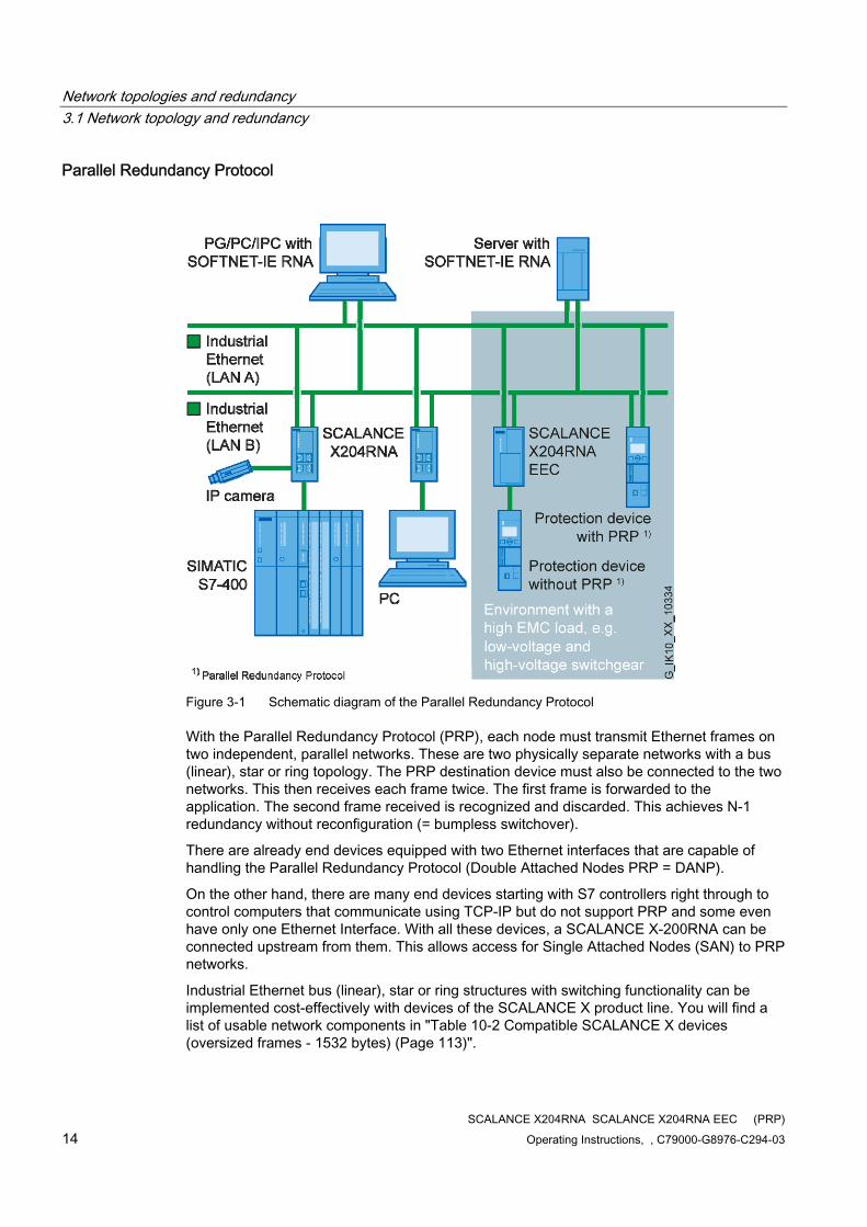
Figure 3-1 Schematic diagram of the Parallel Redundancy Protocol
With the Parallel Redundancy Protocol (PRP), each node must transmit Ethernet frames on two independent, parallel networks. These are two physically separate networks with a bus (linear), star or ring topology. The PRP destination device must also be connected to the two networks. This then receives each frame twice. The first frame is forwarded to the application. The second frame received is recognized and discarded. This achieves N-1 redundancy without reconfiguration (= bumpless switchover).
There are already end devices equipped with two Ethernet interfaces that are capable of handling the Parallel Redundancy Protocol (Double Attached Nodes PRP = DANP).
On the other hand, there are many end devices starting with S7 controllers right through to control computers that communicate using TCP-IP but do not support PRP and some even have only one Ethernet Interface. With all these devices, a SCALANCE X-200RNA can be connected upstream from them. This allows access for Single Attached Nodes (SAN) to PRP networks.
Industrial Ethernet bus (linear), star or ring structures with switching functionality can be implemented cost-effectively with devices of the SCALANCE X product line. You will find a list of usable network components in "Table 10-2 Compatible SCALANCE X devices (oversized frames - 1532 bytes) (Page 113)".
SCALANCE X204RNA SCALANCE X204RNA EEC (PRP) Operating Instructions, , C79000-G8976-C294-03 15
Product characteristics 44.1 Overview of the product characteristics
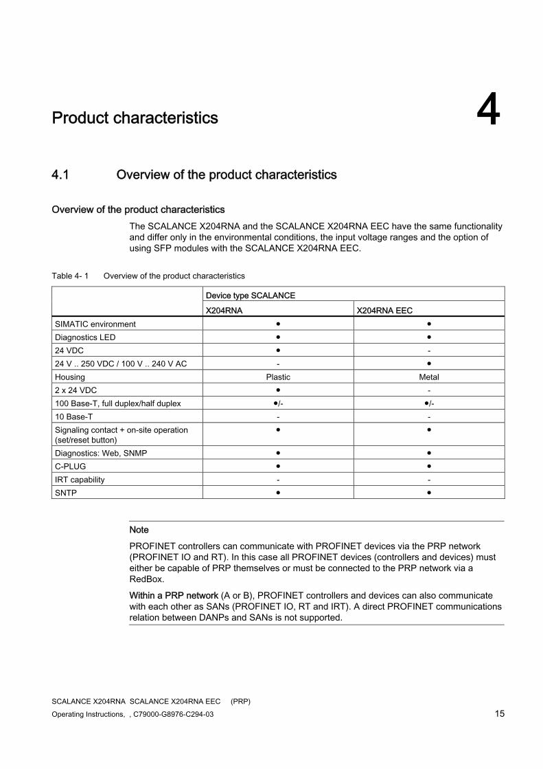
Overview of the product characteristics The SCALANCE X204RNA and the SCALANCE X204RNA EEC have the same functionality and differ only in the environmental conditions, the input voltage ranges and the option of using SFP modules with the SCALANCE X204RNA EEC.
Table 4- 1 Overview of the product characteristics
Device type SCALANCE
X204RNA X204RNA EEC SIMATIC environment ● ● Diagnostics LED ● ● 24 VDC ● - 24 V .. 250 VDC / 100 V .. 240 V AC - ● Housing Plastic Metal 2 x 24 VDC ● - 100 Base-T, full duplex/half duplex ●/- ●/- 10 Base-T - - Signaling contact + on-site operation (set/reset button)
● ●
Diagnostics: Web, SNMP ● ● C-PLUG ● ● IRT capability - - SNTP ● ●
Note
PROFINET controllers can communicate with PROFINET devices via the PRP network (PROFINET IO and RT). In this case all PROFINET devices (controllers and devices) must either be capable of PRP themselves or must be connected to the PRP network via a RedBox.
Within a PRP network (A or B), PROFINET controllers and devices can also communicate with each other as SANs (PROFINET IO, RT and IRT). A direct PROFINET communications relation between DANPs and SANs is not supported.
Product characteristics 4.1 Overview of the product characteristics
SCALANCE X204RNA SCALANCE X204RNA EEC (PRP) 16 Operating Instructions, , C79000-G8976-C294-03
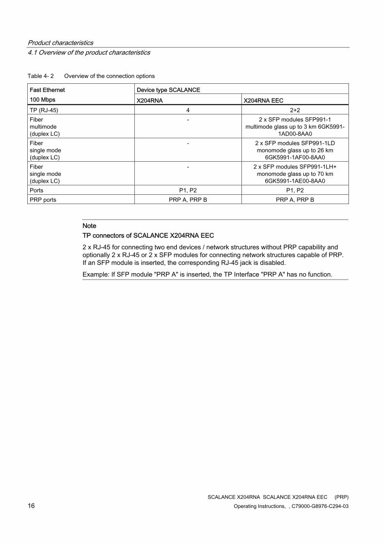
Table 4- 2 Overview of the connection options
Device type SCALANCE Fast Ethernet 100 Mbps X204RNA X204RNA EEC TP (RJ-45) 4 2+2 Fiber multimode (duplex LC)
- 2 x SFP modules SFP991-1 multimode glass up to 3 km 6GK5991-
1AD00-8AA0 Fiber single mode (duplex LC)
- 2 x SFP modules SFP991-1LD monomode glass up to 26 km
6GK5991-1AF00-8AA0 Fiber single mode (duplex LC)
- 2 x SFP modules SFP991-1LH+ monomode glass up to 70 km
6GK5991-1AE00-8AA0 Ports P1, P2 P1, P2 PRP ports PRP A, PRP B PRP A, PRP B
Note TP connectors of SCALANCE X204RNA EEC
2 x RJ-45 for connecting two end devices / network structures without PRP capability and optionally 2 x RJ-45 or 2 x SFP modules for connecting network structures capable of PRP. If an SFP module is inserted, the corresponding RJ-45 jack is disabled.
Example: If SFP module "PRP A" is inserted, the TP Interface "PRP A" has no function.
Product characteristics 4.2 Components of the product
SCALANCE X204RNA SCALANCE X204RNA EEC (PRP) Operating Instructions, , C79000-G8976-C294-03 17
4.2 Components of the product
SCALANCE X204RNA The following components are supplied with the SCALANCE X204RNA:
● SCALANCE X204RNA device
● 2-pin plug-in terminal block (signaling contact)
● 4-pin plug-in terminal block (redundant power supply)
● Safety notices
● CD (Operating Instructions, PST Tool)
SCALANCE X204RNA EEC The following components are supplied with the SCALANCE X204RNA EEC:
● SCALANCE X204RNA EEC device
● 3-pin plug-in terminal block (signaling contact)
● 3-pin plug-in terminal block (power supply)
● Safety notices
● CD (Operating Instructions, PST Tool)
● Bracket for guiding the cable (mechanical protection)
4.3 Unpacking and checking
Unpacking, checking 1. Make sure that the package is complete.
2. Check all the parts for transport damage.
WARNING
Do not use any parts that show evidence of damage!
Product characteristics 4.4 SCALANCE X204RNA
SCALANCE X204RNA SCALANCE X204RNA EEC (PRP) 18 Operating Instructions, , C79000-G8976-C294-03
4.4 SCALANCE X204RNA
4.4.1 SCALANCE X204RNA product characteristics
SCALANCE X204RNA product characteristics
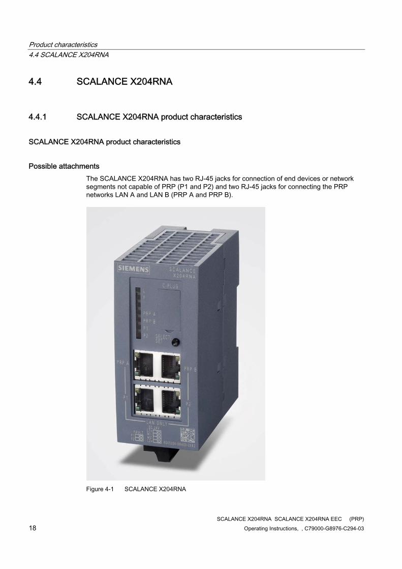
Possible attachments The SCALANCE X204RNA has two RJ-45 jacks for connection of end devices or network segments not capable of PRP (P1 and P2) and two RJ-45 jacks for connecting the PRP networks LAN A and LAN B (PRP A and PRP B).
Figure 4-1 SCALANCE X204RNA
Product characteristics 4.4 SCALANCE X204RNA
SCALANCE X204RNA SCALANCE X204RNA EEC (PRP) Operating Instructions, , C79000-G8976-C294-03 19
4.4.2 SCALANCE X204RNA TP interfaces
SCALANCE X204RNA TP interfaces
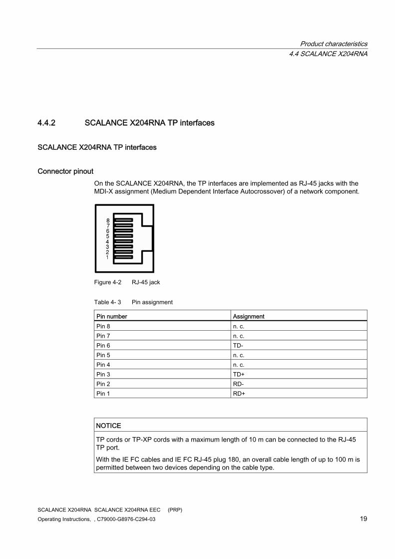
Connector pinout On the SCALANCE X204RNA, the TP interfaces are implemented as RJ-45 jacks with the MDI-X assignment (Medium Dependent Interface Autocrossover) of a network component.
Figure 4-2 RJ-45 jack
Table 4- 3 Pin assignment
Pin number Assignment Pin 8 n. c. Pin 7 n. c. Pin 6 TD- Pin 5 n. c. Pin 4 n. c. Pin 3 TD+ Pin 2 RD- Pin 1 RD+
NOTICE TP cords or TP-XP cords with a maximum length of 10 m can be connected to the RJ-45 TP port.
With the IE FC cables and IE FC RJ-45 plug 180, an overall cable length of up to 100 m is permitted between two devices depending on the cable type.
Product characteristics 4.4 SCALANCE X204RNA
SCALANCE X204RNA SCALANCE X204RNA EEC (PRP) 20 Operating Instructions, , C79000-G8976-C294-03
Note
The interfaces of the SCALANCE X204RNA meet the requirements for environment B according to IEEE 802.3, section 33.4.1.1.
Autonegotiation Autonegotiation means the automatic detection of the functionality of the port at the opposite end. Using autonegotiation, repeaters or end devices can detect the functionality available at the port of a partner device allowing automatic configuration of different types of device. With autonegotiation, two components connected to a link segment can exchange parameters and set themselves to match the supported communication functionality.
Note
The SCALANCE X204RNA operates permanently in autonegotiation mode and can therefore be connected to other devices that either also use the autonegotiation mode or the 100 Mbps mode FD (full duplex).
Note
The SCALANCE X204RNA is a plug-and-play device that does not require settings to be made for commissioning.
MDI / MDIX autocrossover function The advantage of the MDI / MDIX autocrossover function is that straight-through cables can be used throughout and external Ethernet crossover cables are unnecessary. This prevents malfunctions resulting from mismatching send and receive wires. This makes installation much easier for the user.
The SCALANCE X204RNA supports the MDI / MDIX autocrossover function.
Note
Please note that the direct connection of two ports on the switch or accidental connection over several switches causes an illegal loop. Such a loop can lead to network overload and network failures.
Transmission speed The transmission speed of the Fast Ethernet ports is 100 Mbps full duplex.
Product characteristics 4.5 SCALANCE X204RNA EEC
SCALANCE X204RNA SCALANCE X204RNA EEC (PRP) Operating Instructions, , C79000-G8976-C294-03 21
4.5 SCALANCE X204RNA EEC
4.5.1 SCALANCE X204RNA EEC product characteristics
SCALANCE X204RNA EEC product characteristics
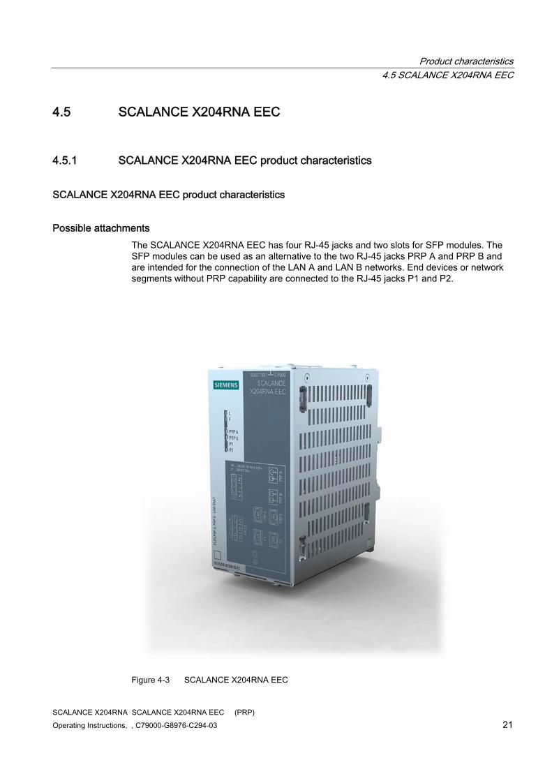
Possible attachments The SCALANCE X204RNA EEC has four RJ-45 jacks and two slots for SFP modules. The SFP modules can be used as an alternative to the two RJ-45 jacks PRP A and PRP B and are intended for the connection of the LAN A and LAN B networks. End devices or network segments without PRP capability are connected to the RJ-45 jacks P1 and P2.
Figure 4-3 SCALANCE X204RNA EEC
Product characteristics 4.5 SCALANCE X204RNA EEC
SCALANCE X204RNA SCALANCE X204RNA EEC (PRP) 22 Operating Instructions, , C79000-G8976-C294-03
4.5.2 SCALANCE X204RNA EEC TP interfaces
SCALANCE X204RNA EEC TP interfaces
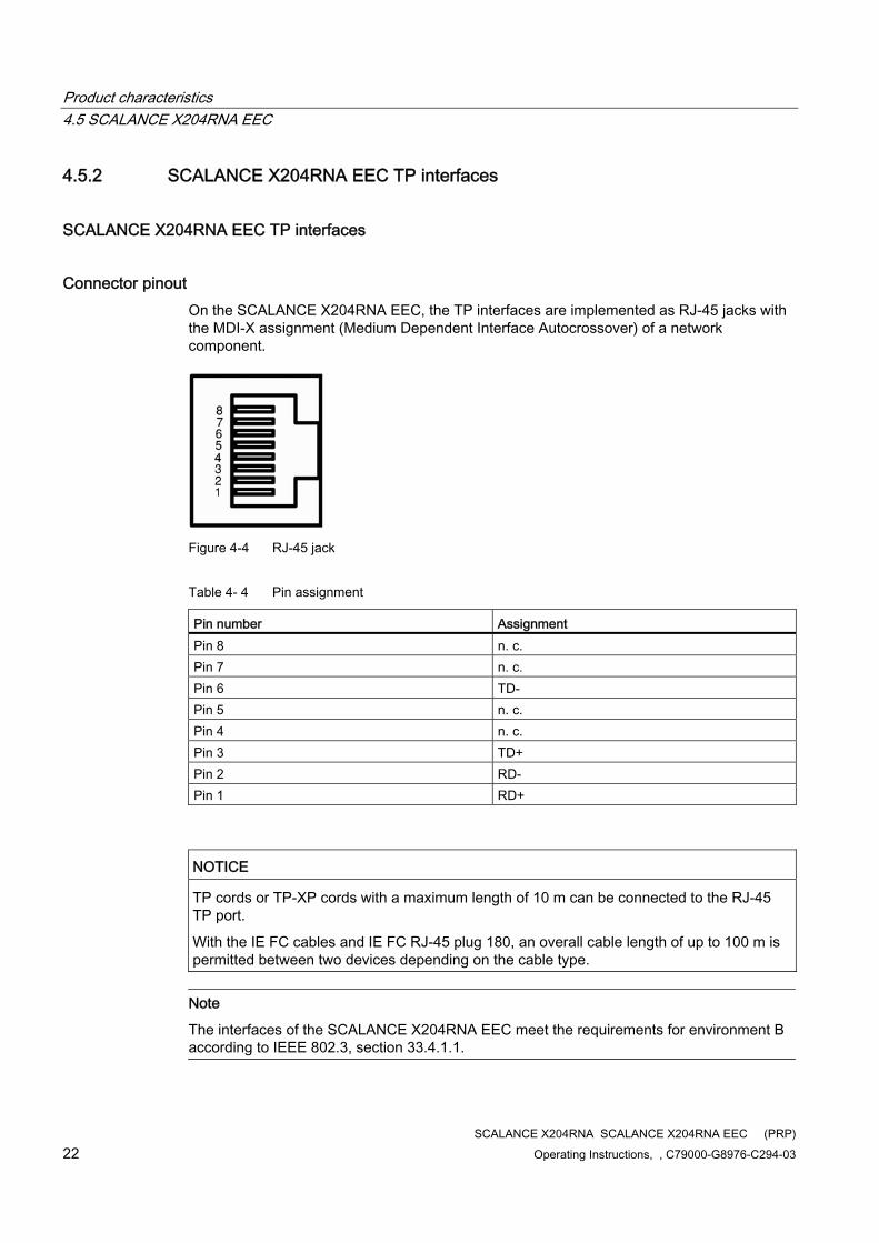
Connector pinout On the SCALANCE X204RNA EEC, the TP interfaces are implemented as RJ-45 jacks with the MDI-X assignment (Medium Dependent Interface Autocrossover) of a network component.
Figure 4-4 RJ-45 jack
Table 4- 4 Pin assignment
Pin number Assignment Pin 8 n. c. Pin 7 n. c. Pin 6 TD- Pin 5 n. c. Pin 4 n. c. Pin 3 TD+ Pin 2 RD- Pin 1 RD+
NOTICE TP cords or TP-XP cords with a maximum length of 10 m can be connected to the RJ-45 TP port.
With the IE FC cables and IE FC RJ-45 plug 180, an overall cable length of up to 100 m is permitted between two devices depending on the cable type.
Note
The interfaces of the SCALANCE X204RNA EEC meet the requirements for environment B according to IEEE 802.3, section 33.4.1.1.
Product characteristics 4.5 SCALANCE X204RNA EEC
SCALANCE X204RNA SCALANCE X204RNA EEC (PRP) Operating Instructions, , C79000-G8976-C294-03 23
Autonegotiation Autonegotiation means the automatic detection of the functionality of the port at the opposite end. Using autonegotiation, repeaters or end devices can detect the functionality available at the port of a partner device allowing automatic configuration of different types of device. With autonegotiation, two components connected to a link segment can exchange parameters and set themselves to match the supported communication functionality.
Note
The SCALANCE X204RNA EEC operates permanently in autonegotiation mode and can therefore be connected to other devices that either also use the autonegotiation mode or the 100 Mbps mode FD (full duplex).
Note
The SCALANCE X204RNA EEC is a plug-and-play device that does not require settings to be made for commissioning.
MDI / MDIX autocrossover function The advantage of the MDI / MDIX autocrossover function is that straight-through cables can be used throughout and external Ethernet crossover cables are unnecessary. This prevents malfunctions resulting from mismatching send and receive wires. This makes installation much easier for the user.
The SCALANCE X204RNA EEC supports the MDI / MDIX autocrossover function.
Note
Please note that the direct connection of two ports on the switch or accidental connection over several switches causes an illegal loop. Such a loop can lead to network overload and network failures.
Transmission speed The transmission speed of the Fast Ethernet ports is 100 Mbps full duplex.
4.5.3 SCALANCE X204RNA EEC SFP interface
SCALANCE X204RNA EEC SFP interface The SFF slots are used to insert suitable SFP modules.
Here the use of transceivers with an optical interface is particularly practical.
Product characteristics 4.5 SCALANCE X204RNA EEC
SCALANCE X204RNA SCALANCE X204RNA EEC (PRP) 24 Operating Instructions, , C79000-G8976-C294-03
Transmission medium and range
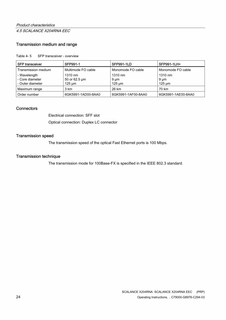
Table 4- 5 SFP transceiver - overview
SFP transceiver SFP991-1 SFP991-1LD SFP991-1LH+ Transmission medium - Wavelength - Core diameter - Outer diameter
Multimode FO cable 1310 nm 50 or 62.5 µm 125 µm
Monomode FO cable 1310 nm 9 µm 125 µm
Monomode FO cable 1310 nm 9 µm 125 µm
Maximum range 3 km 26 km 70 km Order number 6GK5991-1AD00-8AA0 6GK5991-1AF00-8AA0 6GK5991-1AE00-8AA0
Connectors Electrical connection: SFF slot
Optical connection: Duplex LC connector
Transmission speed The transmission speed of the optical Fast Ethernet ports is 100 Mbps.
Transmission technique The transmission mode for 100Base-FX is specified in the IEEE 802.3 standard.
Product characteristics 4.6 C-PLUG
SCALANCE X204RNA SCALANCE X204RNA EEC (PRP) Operating Instructions, , C79000-G8976-C294-03 25
4.6 C-PLUG
CPLUG (configuration plug)
Area of application The C-PLUG is an exchangeable medium for storage of the configuration and project engineering data of the basic device. This means that the configuration data remains available if the basic device is replaced.
How it works Power is supplied by the basic device. The C-PLUG retains all data permanently when the power is turned off.
If an empty C-PLUG (factory settings) is inserted, all configuration data of the SCALANCE X-200RNA is saved to it when the device starts up. Changes to the configuration during operation are also saved on the C-PLUG without any operator intervention being necessary.
A basic device with an inserted C-PLUG automatically uses the configuration data of the C-PLUG when it starts up. This is, however, only possible when the data was written by a compatible device type.
This allows fast and simple replacement of the basic device. If a device needs to be replaced, the C-PLUG is simply taken from the failed component and inserted in the replacement device. The first time it is started up, the replacement device has the same configuration as the failed device except for the MAC address set by the vendor.
Compatible devices As a general rule, the data on the C-PLUG is only compatible with devices having an identical order number and the same device name.
Over and above this, the data of the SCALANCE X204RNA and the SCALANCE X204RNA is compatible.
Using a previously written C-PLUG If you want to insert a C-PLUG that has already been used and has been written to in a SCALANCE X-200RNA with a different configuration, the existing C-PLUG data must first be deleted.
Note
An IE Switch X-200 normally starts up with the configuration of the C-PLUG, assuming this was written to by a compatible device type.
Product characteristics 4.6 C-PLUG
SCALANCE X204RNA SCALANCE X204RNA EEC (PRP) 26 Operating Instructions, , C79000-G8976-C294-03
Diagnostics Inserting a C-PLUG that does not contain the configuration of a compatible device type or general malfunctions of the C-PLUG are signaled by the diagnostics mechanisms of the SCALANCE X-200RNA (LEDs, SNMP, WBM, etc.).
Inserting in the C-PLUG slot The C-PLUG is not supplied with the SCALANCE X-200RNA. It is available as an optional accessory.
The slot for the C-PLUG is located as follows:
●With a SCALANCE X204RNA on the front of the device
●With the SCALANCE X204RNA EEC on the top of the device
Refer to Figure 4-6 Position of the C-PLUG and SET button (Page 28)
To insert the C-PLUG, remove the protective cover. The C-PLUG is inserted in the slot.
The protective cover must then be closed correctly.
NOTICE The C-PLUG may only be inserted or removed when the power is off!
Removing the C-PLUG It is only necessary to remove the C-PLUG if a fault occurs on the SCALANCE X-200RNA.
The C-PLUG can be removed from the slot using flat pliers, tweezers, or a small screwdriver.
See also SET button (Page 27)
Product characteristics 4.7 SET button
SCALANCE X204RNA SCALANCE X204RNA EEC (PRP) Operating Instructions, , C79000-G8976-C294-03 27
4.7 SET button
SET button
Button function You can change various device settings with the button. Modified settings are retained after device power off/on.
The SELECT / SET button is used to switch over the display mode and to make other settings. After turning on the SCALANCE X-200RNA, it is in the display mode.
The button has three functions:
● Triggering a device restart
● Reset to the factory defaults All settings made are overwritten by the factory defaults.
● Define the fault mask and the display at the LEDs. The current states of all ports and the states of the power supplies L1 and L2 are included in the fault mask. The previous fault mask is then overwritten.
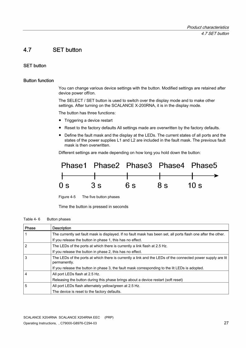
Different settings are made depending on how long you hold down the button:
Figure 4-5 The five button phases
Time the button is pressed in seconds
Table 4- 6 Button phases
Phase Description 1 The currently set fault mask is displayed. If no fault mask has been set, all ports flash one after the other.
If you release the button in phase 1, this has no effect. 2 The LEDs of the ports at which there is currently a link flash at 2.5 Hz.
If you release the button in phase 2, this has no effect. 3 The LEDs of the ports at which there is currently a link and the LEDs of the connected power supply are lit
permanently. If you release the button in phase 3, the fault mask corresponding to the lit LEDs is adopted.
4 All port LEDs flash at 2.5 Hz. Releasing the button during this phase brings about a device restart (soft reset)
5 All port LEDs flash alternately yellow/green at 2.5 Hz. The device is reset to the factory defaults.
Product characteristics 4.7 SET button
SCALANCE X204RNA SCALANCE X204RNA EEC (PRP) 28 Operating Instructions, , C79000-G8976-C294-03
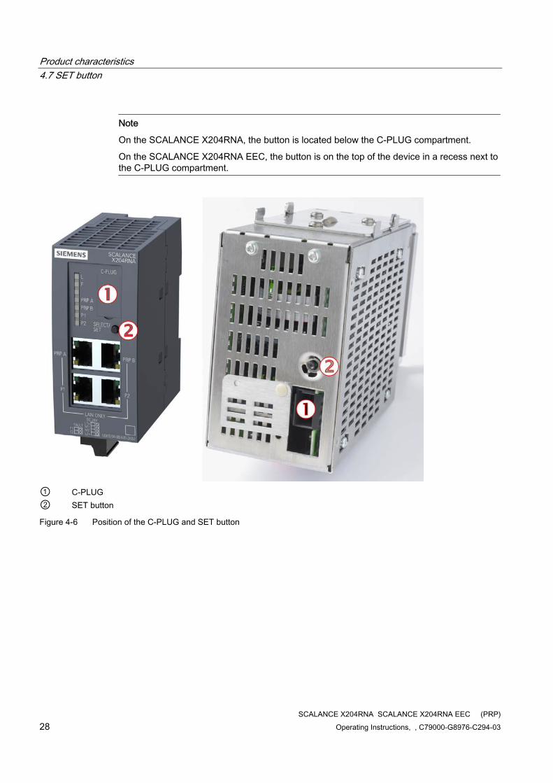
Note
On the SCALANCE X204RNA, the button is located below the C-PLUG compartment.
On the SCALANCE X204RNA EEC, the button is on the top of the device in a recess next to the C-PLUG compartment.
① C-PLUG ② SET button
Figure 4-6 Position of the C-PLUG and SET button
Product characteristics 4.8 Displays
SCALANCE X204RNA SCALANCE X204RNA EEC (PRP) Operating Instructions, , C79000-G8976-C294-03 29
4.8 Displays
4.8.1 Fault indicator (yellow/red LED)
Fault indicator (yellow/red LED) If the LED is lit red, a SCALANCE X-200RNA has detected an error/fault.
At the same time, the signaling contact opens assuming that the response of the signaling contact has not been configured differently.
The LED signals that the SCALANCE X-200RNA can adopt the following statuses:
Device type SCALANCE LED lit red LED lit yellow LED not lit X204RNA 1, 2, 3, 4, 5 6 7 X204RNA EEC 1, 3, 4, 5 6 7
1. Link down event on a monitored port.
2. Failure of one of the two redundant power supplies.
3. C-PLUG error
4. Device startup, the LED is lit for approx. 20 seconds.
5. Internal error.
6. A redundancy error was detected.
7. No problem has been detected by the SCALANCE X-200RNA.
4.8.2 Power display
Power display The LEDs signal the following statuses of the SCALANCE X-200RNA.
The status of the power supply is indicated by a green LED:
Device type SCALANCE LED lit green LED lit yellow LED not lit X204RNA 1 2 3 X204RNA EEC 4 - 5
1. Both L power supplies are connected (redundant supply).
2. One L power supply is connected (non-redundant supply).
3. Power supply L1 and L2 are not connected or supply voltages are <14 V.
Product characteristics 4.8 Displays
SCALANCE X204RNA SCALANCE X204RNA EEC (PRP) 30 Operating Instructions, , C79000-G8976-C294-03
4. Power supply L is connected
5. Power supply L is not connected or the supply voltage is too low.
4.8.3 Port status indication
Port status indicator (green/yellow LEDs) The LEDs signal the following port statuses of the SCALANCE X-200RNA.
The status of interfaces is indicated by two-color LEDs:
Device type SCALANCE
Number of LEDs
LED lit green LED lit yellow LED flashes yellow
2 port LEDs 1 2, 3 4 X204RNA 2 PRP port LEDs 1 2, 3 4 2 port LEDs 1 2, 3 4 X204RNA EEX 2 PRP port LEDs 1 2, 3 4
1. TP link exists, no data reception.
2. TP link, data received at TP port.
3. Device startup, the LED is lit for approx. 6 seconds.
4. Setting or display of the fault mask.
4.8.4 LED displays during startup
LED displays during startup When a device starts up, the following displays light up in the order shown:
1. Power LEDs (green) light up immediately after turning on the power.
2. Port LEDs go off, the red error LED is lit for approx. 10 seconds.
3. Following startup, the correct link status is indicated by the port LEDs after approximately 5 seconds.
4. The SCALANCE X-200RNA is now ready for operation.
SCALANCE X204RNA SCALANCE X204RNA EEC (PRP) Operating Instructions, , C79000-G8976-C294-03 31
Installation 55.1 Types of installation
Types of installation The SCALANCE X-200RNA devices can be mounted on a 35 mm DIN rail. Wall mounting is also possible.
Note
Installation on a SIMATIC S7-300 standard rail is not possible
Note
When installing and operating the device, keep to the installation instructions and safety-related notices in this description and in the SIMATIC NET Industrial Ethernet network manual (Page 117).
Unless stated otherwise, the mounting options listed below apply to all SCALANCE X-200RNA devices.
Note
Provide suitable shade to protect the SCALANCE X-200RNA devices against direct sunlight. This avoids unwanted warming of the SCALANCE X-200RNA devices and prevents premature aging of the device and cabling.
WARNING If a SCALANCE X204RNA EEC is operated at ambient temperatures between 60 °C and 70 °C, the housing temperature may exceed 70 °C.
When installing the X204RNA EEC, select a location where only qualified service personnel or trained users have access to it.
Operation of the SCALANCE X204RNA EEC at ambient temperatures of 60 °C - 70 °C is only permitted under these conditions.
WARNING If temperatures in excess of 70 °C occur on cables or at cable feed-in points, or the temperature at the branching point of the cables exceeds 80 °C, special measures need to be taken. If the equipment is operated at an ambient temperature of 50 °C - 60 °C, use cables with a permitted ambient temperature of at least 80 °C.
Installation 5.1 Types of installation
SCALANCE X204RNA SCALANCE X204RNA EEC (PRP) 32 Operating Instructions, , C79000-G8976-C294-03
CAUTION Do not cover the ventilation grilles
During installation, select a mounting position so that the ventilation grilles are always free to achieve adequate cooling. With normal orientation, the ventilation grilles are on the top, bottom and sides (X204RNA EEC only) of the housing.
Minimum clearances If you install the SCALANCE X-200RNA without forced ventilation or cooling, minimum clearances must be maintained to neighboring devices or the wall of the housing. By keeping to the minimum clearances, there is then an adequate stream of air for heat dissipation during operation. Keep to the following minimum clearances to neighboring devices.
Table 5- 1 Minimum clearances when installing in cabinets
Minimum clearance to devices below the X-200RNA 100 mm Minimum clearance to devices above the X-200RNA 100 mm Minimum lateral clearance to devices (X204RNA EEC only) 20 mm
Installation 5.2 Mounting on DIN rails
SCALANCE X204RNA SCALANCE X204RNA EEC (PRP) Operating Instructions, , C79000-G8976-C294-03 33
5.2 Mounting on DIN rails
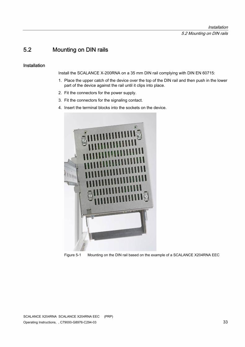
Installation Install the SCALANCE X-200RNA on a 35 mm DIN rail complying with DIN EN 60715:
1. Place the upper catch of the device over the top of the DIN rail and then push in the lower part of the device against the rail until it clips into place.
2. Fit the connectors for the power supply.
3. Fit the connectors for the signaling contact.
4. Insert the terminal blocks into the sockets on the device.
Figure 5-1 Mounting on the DIN rail based on the example of a SCALANCE X204RNA EEC
Installation 5.2 Mounting on DIN rails
SCALANCE X204RNA SCALANCE X204RNA EEC (PRP) 34 Operating Instructions, , C79000-G8976-C294-03
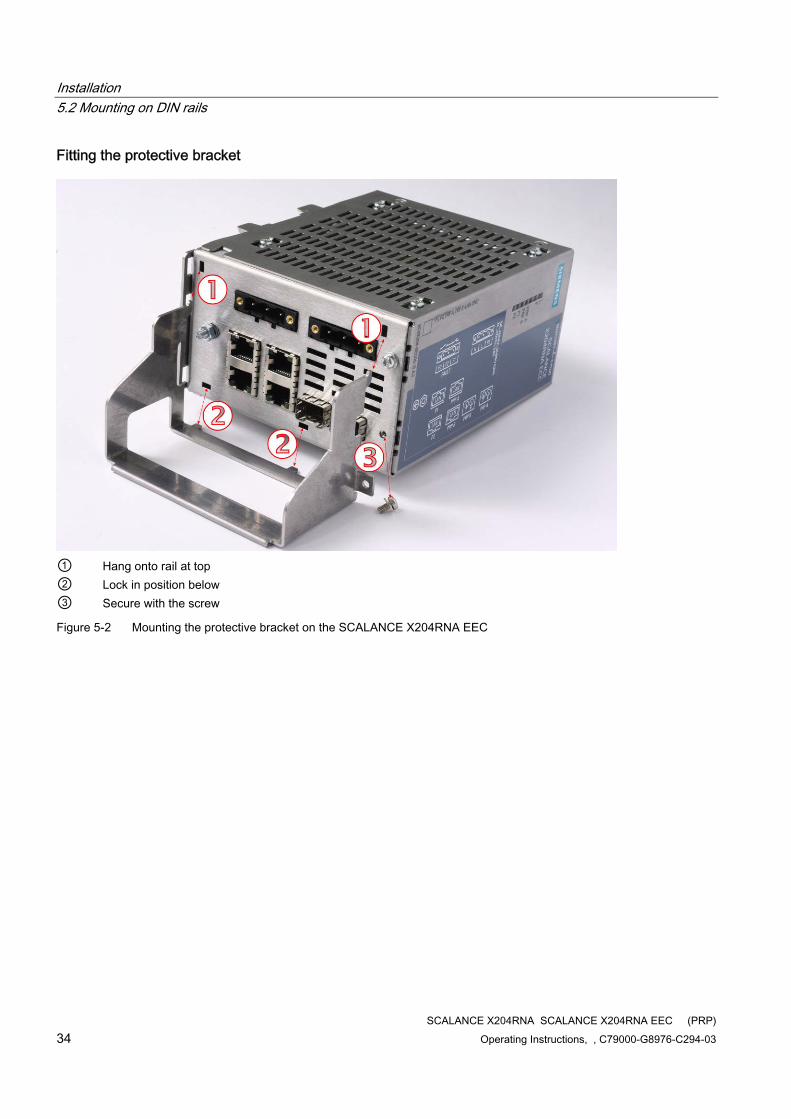
Fitting the protective bracket
① Hang onto rail at top ② Lock in position below ③ Secure with the screw
Figure 5-2 Mounting the protective bracket on the SCALANCE X204RNA EEC
Installation 5.2 Mounting on DIN rails
SCALANCE X204RNA SCALANCE X204RNA EEC (PRP) Operating Instructions, , C79000-G8976-C294-03 35
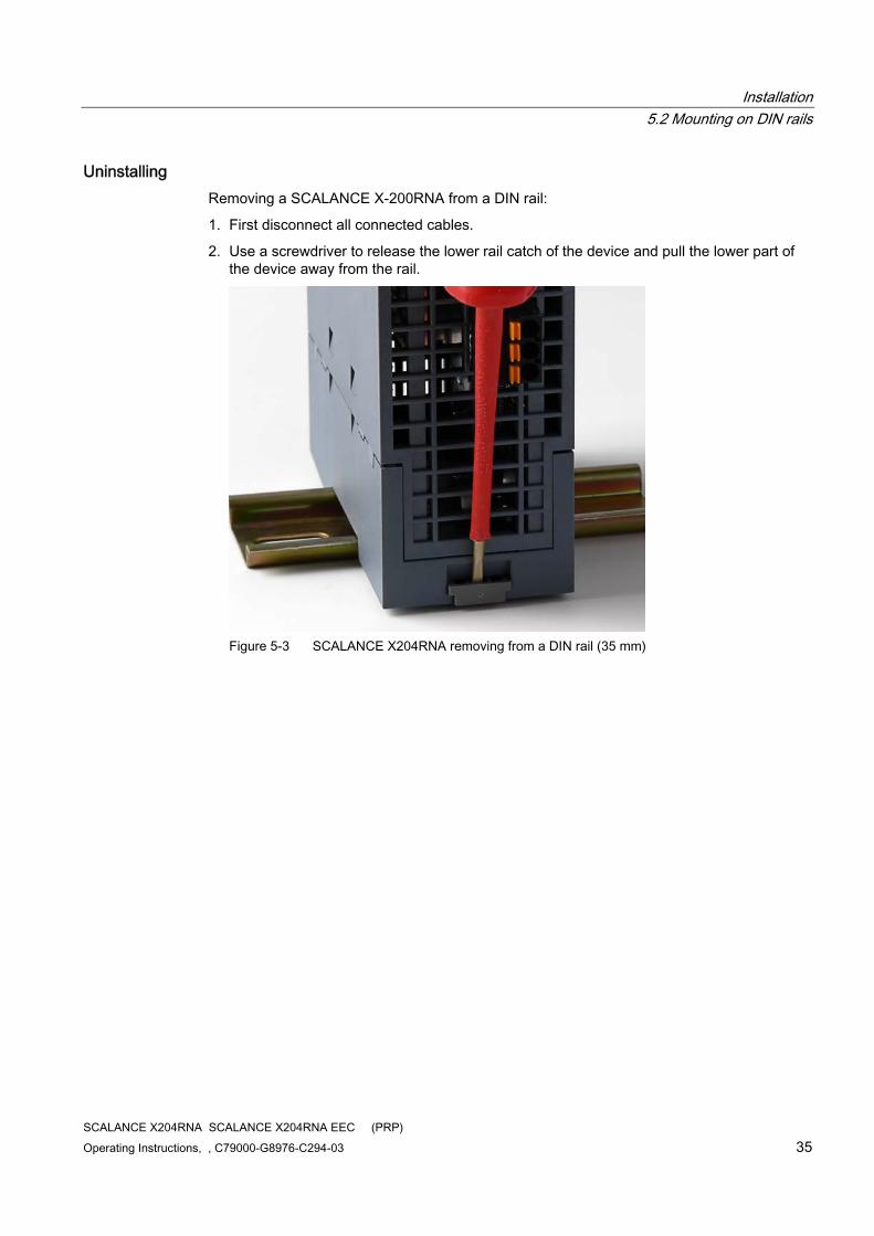
Uninstalling Removing a SCALANCE X-200RNA from a DIN rail:
1. First disconnect all connected cables.
2. Use a screwdriver to release the lower rail catch of the device and pull the lower part of the device away from the rail.
Figure 5-3 SCALANCE X204RNA removing from a DIN rail (35 mm)
Installation 5.3 Wall mounting
SCALANCE X204RNA SCALANCE X204RNA EEC (PRP) 36 Operating Instructions, , C79000-G8976-C294-03
5.3 Wall mounting
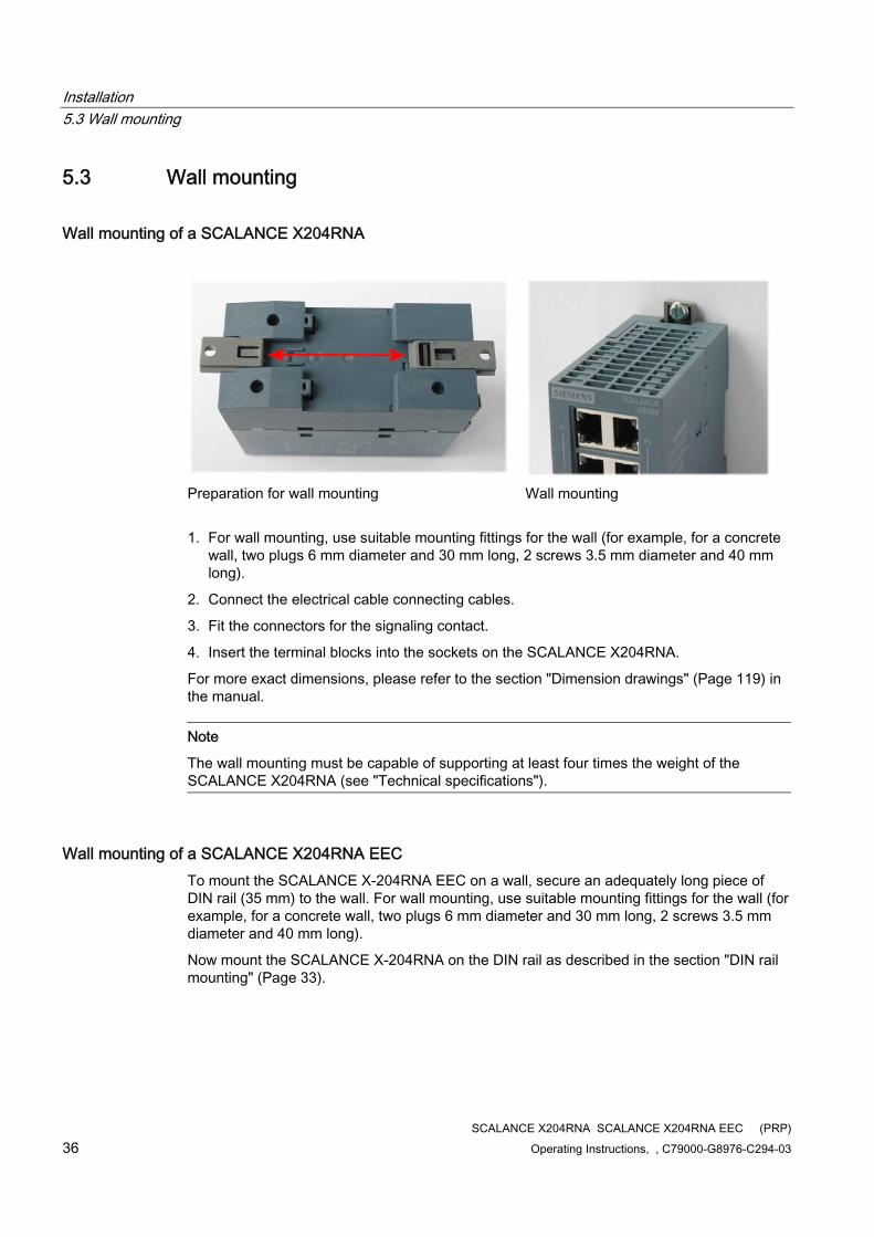
Wall mounting of a SCALANCE X204RNA
Preparation for wall mounting
Wall mounting
1. For wall mounting, use suitable mounting fittings for the wall (for example, for a concrete wall, two plugs 6 mm diameter and 30 mm long, 2 screws 3.5 mm diameter and 40 mm long).
2. Connect the electrical cable connecting cables.
3. Fit the connectors for the signaling contact.
4. Insert the terminal blocks into the sockets on the SCALANCE X204RNA.
For more exact dimensions, please refer to the section "Dimension drawings" (Page 119) in the manual.
Note
The wall mounting must be capable of supporting at least four times the weight of the SCALANCE X204RNA (see "Technical specifications").
Wall mounting of a SCALANCE X204RNA EEC To mount the SCALANCE X-204RNA EEC on a wall, secure an adequately long piece of DIN rail (35 mm) to the wall. For wall mounting, use suitable mounting fittings for the wall (for example, for a concrete wall, two plugs 6 mm diameter and 30 mm long, 2 screws 3.5 mm diameter and 40 mm long).
Now mount the SCALANCE X-204RNA on the DIN rail as described in the section "DIN rail mounting" (Page 33).
SCALANCE X204RNA SCALANCE X204RNA EEC (PRP) Operating Instructions, , C79000-G8976-C294-03 37
Connection 66.1 Power supply
Power supply The power supply is connected using a 3- or 4-pin plug-in terminal block. Usable cable cross-section 0.25 to 2.5 mm2. Tightening torque 0.57 - 0.79 Nm (5 - 7 in.lb.).
The power supply is non-floating. The signal cables of the Ethernet TP ports are floating.
Note
Removing or inserting the power connector with the power on is not permitted.
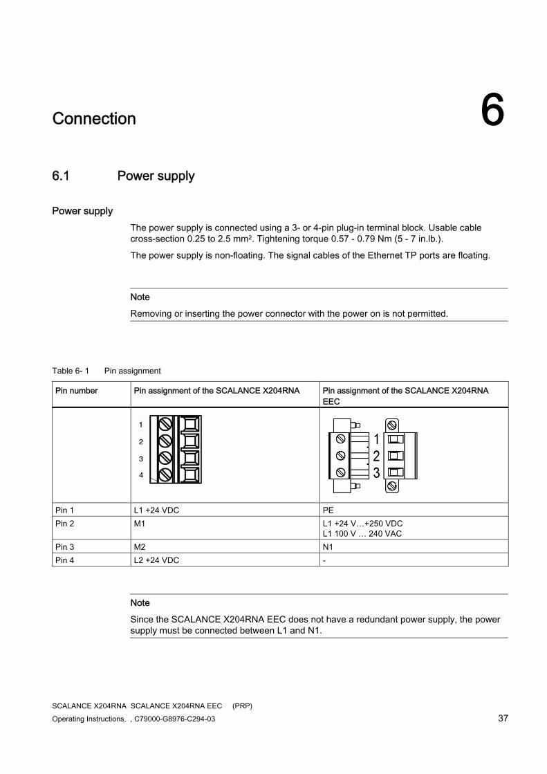
Table 6- 1 Pin assignment
Pin number Pin assignment of the SCALANCE X204RNA Pin assignment of the SCALANCE X204RNA EEC
Pin 1 L1 +24 VDC PE Pin 2 M1 L1 +24 V…+250 VDC
L1 100 V … 240 VAC Pin 3 M2 N1 Pin 4 L2 +24 VDC -
Note
Since the SCALANCE X204RNA EEC does not have a redundant power supply, the power supply must be connected between L1 and N1.
Connection 6.1 Power supply
SCALANCE X204RNA SCALANCE X204RNA EEC (PRP) 38 Operating Instructions, , C79000-G8976-C294-03
WARNING The SCALANCE X204RNA is designed for operation with safety extra-low voltage (SELV). This means that only safety extra-low voltages (SELV) complying with IEC950/EN60950/ VDE0805 can be connected to the power supply terminals.
Measures must be taken to prevent transient overvoltages of more than 40% of the rated voltage. This is the case if the devices are operated exclusively with SELV (Safety Extra Low Voltage).
The power supply unit for the SCALANCE X204RNA power supply must meet NEC Class 2, as described by the National Electrical Code(r) (ANSI/NFPA 70).
The power of all connected power supply units must total the equivalent of a power source with limited power (LPS limited power source).
If the device is connected to a redundant power supply (two separate power supplies), both must meet these requirements.
The signaling contact can be subjected to a maximum load of 100 mA (safety extra-low voltage (SELV), 24 VDC).
Never operate the SCALANCE X204RNA with AC voltage or DC voltage higher than 28.8 V DC.
24 VDC power supply
CAUTION If the SCALANCE X204RNA is supplied over long 24 V power supply lines or networks, measures are necessary to prevent interference by strong electromagnetic pulses on the supply lines. These can result, for example, due to lightning or switching of large inductive loads.
One of the tests used to attest the immunity of the SCALANCE X204RNA to electromagnetic interference is the "surge immunity test" according to EN61000-4-5. This test requires overvoltage protection for the power supply lines. A suitable device is, for example, the Dehn Blitzductor VT AD 24 V type no. 918 402 or comparable protective element.
Vendor: DEHN+SÖHNE GmbH+Co.KG, Hans-Dehn-Str.1, Postfach 1640, D-92306 Neumarkt, Germany.
Connection 6.1 Power supply
SCALANCE X204RNA SCALANCE X204RNA EEC (PRP) Operating Instructions, , C79000-G8976-C294-03 39
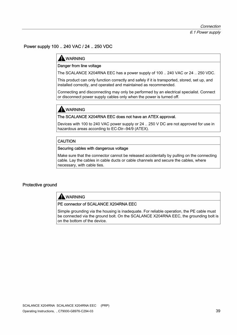
Power supply 100 .. 240 VAC / 24 .. 250 VDC
WARNING Danger from line voltage
The SCALANCE X204RNA EEC has a power supply of 100 .. 240 VAC or 24 .. 250 VDC.
This product can only function correctly and safely if it is transported, stored, set up, and installed correctly, and operated and maintained as recommended.
Connecting and disconnecting may only be performed by an electrical specialist. Connect or disconnect power supply cables only when the power is turned off.
WARNING The SCALANCE X204RNA EEC does not have an ATEX approval.
Devices with 100 to 240 VAC power supply or 24 .. 250 V DC are not approved for use in hazardous areas according to EC-Dir--94/9 (ATEX).
CAUTION Securing cables with dangerous voltage
Make sure that the connector cannot be released accidentally by pulling on the connecting cable. Lay the cables in cable ducts or cable channels and secure the cables, where necessary, with cable ties.
Protective ground
WARNING PE connector of SCALANCE X204RNA EEC
Simple grounding via the housing is inadequate. For reliable operation, the PE cable must be connected via the ground bolt. On the SCALANCE X204RNA EEC, the grounding bolt is on the bottom of the device.
Connection 6.2 Signaling contact
SCALANCE X204RNA SCALANCE X204RNA EEC (PRP) 40 Operating Instructions, , C79000-G8976-C294-03
6.2 Signaling contact
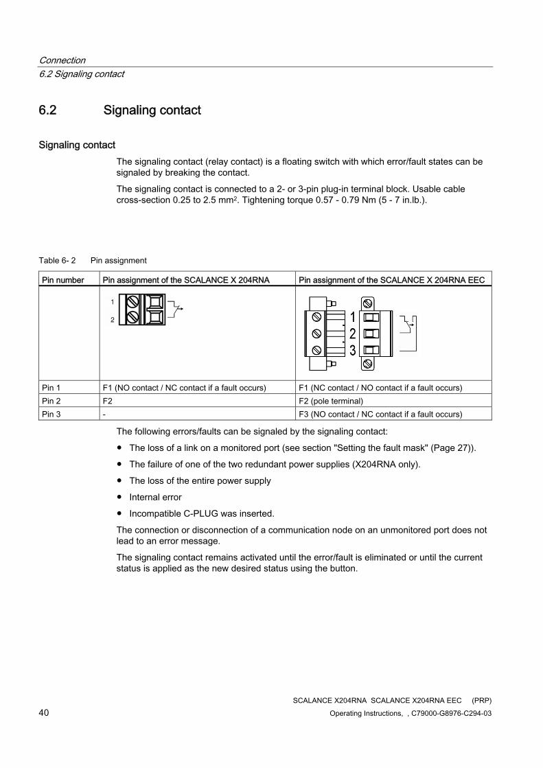
Signaling contact The signaling contact (relay contact) is a floating switch with which error/fault states can be signaled by breaking the contact.
The signaling contact is connected to a 2- or 3-pin plug-in terminal block. Usable cable cross-section 0.25 to 2.5 mm2. Tightening torque 0.57 - 0.79 Nm (5 - 7 in.lb.).
Table 6- 2 Pin assignment
Pin number Pin assignment of the SCALANCE X 204RNA Pin assignment of the SCALANCE X 204RNA EEC
Pin 1 F1 (NO contact / NC contact if a fault occurs) F1 (NC contact / NO contact if a fault occurs) Pin 2 F2 F2 (pole terminal) Pin 3 - F3 (NO contact / NC contact if a fault occurs)
The following errors/faults can be signaled by the signaling contact:
● The loss of a link on a monitored port (see section "Setting the fault mask" (Page 27)).
● The failure of one of the two redundant power supplies (X204RNA only).
● The loss of the entire power supply
● Internal error
● Incompatible C-PLUG was inserted.
The connection or disconnection of a communication node on an unmonitored port does not lead to an error message.
The signaling contact remains activated until the error/fault is eliminated or until the current status is applied as the new desired status using the button.
Connection 6.3 Connecting the SFP transceiver
SCALANCE X204RNA SCALANCE X204RNA EEC (PRP) Operating Instructions, , C79000-G8976-C294-03 41
When the SCALANCE X-200RNA is turned off, the signaling contact is always activated (signals "error/fault").
Note
The signaling contact correlates with the red fault LED.
Exception: The absence of the power supply is signaled only by the signaling contact (no display by the fault LEDs).
Note
During startup, the signaling contract is always active (signals "error/fault").
6.3 Connecting the SFP transceiver
Connecting the SFP transceiver The SFP modules are supplied with power via the SFF slot of the SCALANCE X204RNA EEC.
6.4 Grounding
Grounding
SCALANCE X204RNA The housing is made of plastic. There is no need and no possibility of grounding.
SCALANCE X204RNA EEC The device is grounded over the DIN rail. There is also a grounding bolt on the underside of the housing. Connect the grounding bolt of the device to the nearest grounding point using the grounding cable. To do this use the same wire cross-section as the power supply cable, however not smaller than 1.5 mm²/16 AWG.

Connection 6.4 Grounding
SCALANCE X204RNA SCALANCE X204RNA EEC (PRP) 42 Operating Instructions, , C79000-G8976-C294-03
SCALANCE X204RNA SCALANCE X204RNA EEC (PRP) Operating Instructions, , C79000-G8976-C294-03 43
Functional description and configuration using Web based Management 77.1 Introduction
Introduction To make the best possible use of the technical possibilities of the SCALANCE X-200RNA devices, you can adapt the configuration of the device to the concrete situation in which it is used.
Web Based Management (WBM) accesses the configuration of the SCALANCE X-200RNA using a Web browser. An Ethernet connection to the device is necessary.
NOTICE To prevent unauthorized access to the SCALANCE X200RNA, there is an automatic logout after the 15 minutes or after the time configured in the Agent Timeout Configuration menu. A manual logout is also possible with the appropriate button in the user interface. Exiting the browser does does not close the session. If the browser is started again within the timeout, the session continues to be used.
Note
To use SNMP Management and traps, you require a network management station. This does not ship with IE switches.
Functional description and configuration using Web based Management 7.2 Prerequisite
SCALANCE X204RNA SCALANCE X204RNA EEC (PRP) 44 Operating Instructions, , C79000-G8976-C294-03
7.2 Prerequisite
Note
The screens described in this section apply to the SCALANCE X-200RNA devices. The screens of the SCALANCE X204RNA EEC were chosen to illustrate the examples. Any significant deviations from the screens of the SCALANCE X204RNA are pointed out or shown.
Principle of Web Based Management The SCALANCE X-200RNA devices have an integrated HTTP server for Web Based Management. If a SCALANCE X-200RNA is addressed using a Web browser, it returns HTML pages to the client computer depending on the user input.
The user enters the configuration data in the HTML pages sent by the SCALANCE X-200RNA. A SCALANCE X-200RNA evaluates this information and generates reply pages dynamically. The great advantage of this method is that apart from a Web browser, no special software is required on the client.
Requirements for Web Based Management ● A SCALANCE X-200RNA must have an IP address before you can use Web Based
Management.
● To use Web Based Management, there must be an Ethernet connection between the SCALANCE X-200RNA and the client computer.
● Use of a Microsoft Internet Explorer, version 8 or higher is recommended.
● All the pages of Web Based Management require JavaScript. You should therefore make sure that Java Script is enabled in your browser settings.
Note
The browser must not be set so that it reloads the page from the server each time the page is accessed. The updating of the dynamic content of the page is ensured by other mechanisms. In the Internet Explorer, you can make the appropriate setting in the Options > Internet Options > General menu in the section Temporary Internet Files with the Settings button.
Below the text Check for newer versions of stored pages, the Automatically check box must be selected.
● Web Based Management is HTTP- or HTTPS-based, so you must also enable access to port 80 or 443 if you have a firewall installed.
Functional description and configuration using Web based Management 7.2 Prerequisite
SCALANCE X204RNA SCALANCE X204RNA EEC (PRP) Operating Instructions, , C79000-G8976-C294-03 45
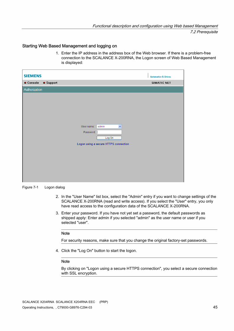
Starting Web Based Management and logging on 1. Enter the IP address in the address box of the Web browser. If there is a problem-free
connection to the SCALANCE X-200RNA, the Logon screen of Web Based Management is displayed:
Figure 7-1 Logon dialog
2. In the "User Name" list box, select the "Admin" entry if you want to change settings of the SCALANCE X-200RNA (read and write access). If you select the "User" entry, you only have read access to the configuration data of the SCALANCE X-200RNA.
3. Enter your password. If you have not yet set a password, the default passwords as shipped apply: Enter admin if you selected "admin" as the user name or user if you selected "user".
Note
For security reasons, make sure that you change the original factory-set passwords.
4. Click the "Log On" button to start the logon.
Note
By clicking on "Logon using a secure HTTPS connection", you select a secure connection with SSL encryption.
Functional description and configuration using Web based Management 7.3 LED simulation of the WBM
SCALANCE X204RNA SCALANCE X204RNA EEC (PRP) 46 Operating Instructions, , C79000-G8976-C294-03
7.3 LED simulation of the WBM
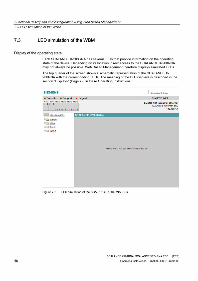
Display of the operating state Each SCALANCE X-200RNA has several LEDs that provide information on the operating state of the device. Depending on its location, direct access to the SCALANCE X-200RNA may not always be possible. Web Based Management therefore displays simulated LEDs.
The top quarter of the screen shows a schematic representation of the SCALANCE X-200RNA with the corresponding LEDs. The meaning of the LED displays is described in the section "Displays" (Page 29) in these Operating Instructions.
Figure 7-2 LED simulation of the SCALANCE X204RNA EEC

Functional description and configuration using Web based Management 7.3 LED simulation of the WBM
SCALANCE X204RNA SCALANCE X204RNA EEC (PRP) Operating Instructions, , C79000-G8976-C294-03 47
Figure 7-3 LED simulation of the SCALANCE X204RNA
Functional description and configuration using Web based Management 7.4 Working with the WBM
SCALANCE X204RNA SCALANCE X204RNA EEC (PRP) 48 Operating Instructions, , C79000-G8976-C294-03
7.4 Working with the WBM
Navigation bar The upper menu bar of WBM contains the following links:
● Console This link opens a Telnet connection to the module. Note: With the Windows 7 operating systems or with Internet Explorer 8, access to the devices via the console link in WEB management is no longer possible.
● Support When you click this link, you open a SIEMENS AG support page. SIEMENS Support is, however, only accessible when your PC has a connection to the Internet.
● Logout By clicking on this link, you log out from the device.
Updating the display with "Refresh" Web Based Management pages have a "Refresh" button at the lower edge of the page. Click this button to request up-to-date information from the IE switch for the current page.
Storing entries with "Set Values" Pages in which you can make configuration settings have a "Set Values" button at the lower edge. Click this button to save the configuration data you have entered on the IE switch.
Note
Changing configuration data is possible only with the "Administrator" login.
Functional description and configuration using Web based Management 7.5 The System menu
SCALANCE X204RNA SCALANCE X204RNA EEC (PRP) Operating Instructions, , C79000-G8976-C294-03 49
7.5 The System menu
7.5.1 System Configuration
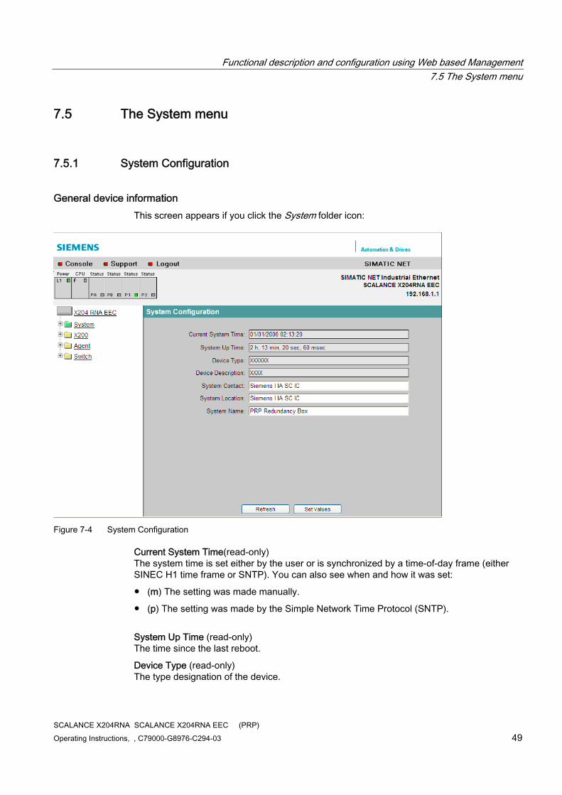
General device information This screen appears if you click the System folder icon:
Figure 7-4 System Configuration
Current System Time(read-only) The system time is set either by the user or is synchronized by a time-of-day frame (either SINEC H1 time frame or SNTP). You can also see when and how it was set:
● (m) The setting was made manually.
● (p) The setting was made by the Simple Network Time Protocol (SNTP).
System Up Time (read-only) The time since the last reboot.
Device Type (read-only) The type designation of the device.
Functional description and configuration using Web based Management 7.5 The System menu
SCALANCE X204RNA SCALANCE X204RNA EEC (PRP) 50 Operating Instructions, , C79000-G8976-C294-03
Device Description (read-only) The type description of the device.
System Contact Enter the name of a contact person responsible for managing the device in this box.
System Location In this box, you enter a location for the device, for example a room number.
System Name Enter a description of the device in this box.
7.5.2 System Identification & Maintenance
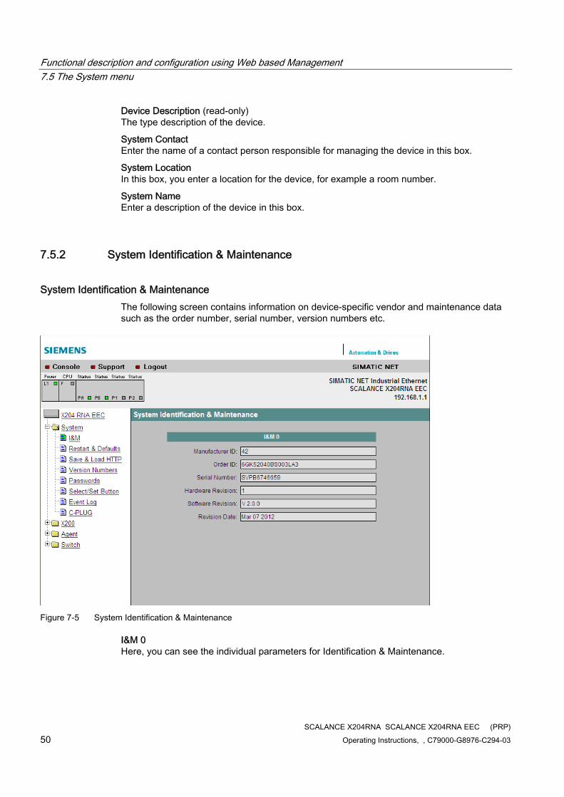
System Identification & Maintenance The following screen contains information on device-specific vendor and maintenance data such as the order number, serial number, version numbers etc.
Figure 7-5 System Identification & Maintenance
I&M 0 Here, you can see the individual parameters for Identification & Maintenance.
Functional description and configuration using Web based Management 7.5 The System menu
SCALANCE X204RNA SCALANCE X204RNA EEC (PRP) Operating Instructions, , C79000-G8976-C294-03 51
7.5.3 System Restart & Defaults
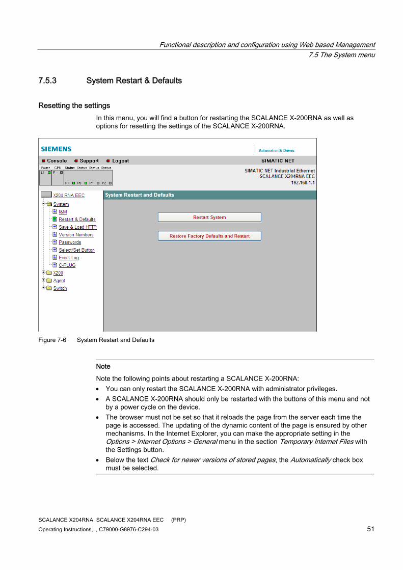
Resetting the settings In this menu, you will find a button for restarting the SCALANCE X-200RNA as well as options for resetting the settings of the SCALANCE X-200RNA.
Figure 7-6 System Restart and Defaults
Note
Note the following points about restarting a SCALANCE X-200RNA: You can only restart the SCALANCE X-200RNA with administrator privileges. A SCALANCE X-200RNA should only be restarted with the buttons of this menu and not
by a power cycle on the device. The browser must not be set so that it reloads the page from the server each time the
page is accessed. The updating of the dynamic content of the page is ensured by other mechanisms. In the Internet Explorer, you can make the appropriate setting in the Options > Internet Options > General menu in the section Temporary Internet Files with the Settings button.
Below the text Check for newer versions of stored pages, the Automatically check box must be selected.
Functional description and configuration using Web based Management 7.5 The System menu
SCALANCE X204RNA SCALANCE X204RNA EEC (PRP) 52 Operating Instructions, , C79000-G8976-C294-03
Restart System Click this button to restart the SCALANCE X-200RNA. You must confirm the restart in a dialog box. During a restart, the SCALANCE X-200RNA is reinitialized, the internal firmware is reloaded, and the device runs a self-test. The learned entries in the address table are deleted. You can leave the browser window open while the SCALANCE X-200RNA restarts.
Restore Factory Defaults and Restart Click this button to restore the factory defaults for the configuration. The protected defaults are also reset. An automatic restart is triggered.
Note
By resetting all the defaults, the IP address is also lost. A SCALANCE X-200RNA can then be accessed using the Primary Setup Tool.
7.5.4 System Save & Load
System Save & Load via HTTP The WBM allows you to store configuration information in an external file on your client PC or to load such data from an external file from the PC to the SCALANCE X-200RNA. You can also download both new firmware as well as a new FPGA configuration from suitable files on your client PC.
Note
Following a firmware update, delete the cache of the Web browser.
Functional description and configuration using Web based Management 7.5 The System menu
SCALANCE X204RNA SCALANCE X204RNA EEC (PRP) Operating Instructions, , C79000-G8976-C294-03 53
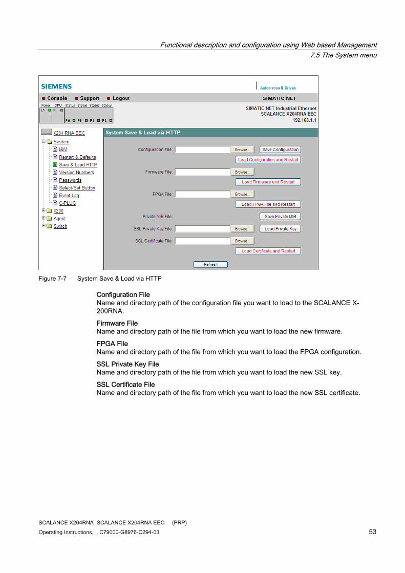
Figure 7-7 System Save & Load via HTTP
Configuration File Name and directory path of the configuration file you want to load to the SCALANCE X-200RNA.
Firmware File Name and directory path of the file from which you want to load the new firmware.
FPGA File Name and directory path of the file from which you want to load the FPGA configuration.
SSL Private Key File Name and directory path of the file from which you want to load the new SSL key.
SSL Certificate File Name and directory path of the file from which you want to load the new SSL certificate.
Functional description and configuration using Web based Management 7.5 The System menu
SCALANCE X204RNA SCALANCE X204RNA EEC (PRP) 54 Operating Instructions, , C79000-G8976-C294-03
How to download data using HTTP 1. In the relevant text box, enter a name and directory path for the file from which you want
to take the data.
2. Start the download of the relevant file by clicking one of the buttons "Load Configuration and Restart", "Load Firmware and Restart" or "Load FPGA File and Restart", "Load Private Key" or "Load Certificate and Restart". Following the download, there is an automatic restart except with "Load Private Key" and the device starts up with the new data. Note the following:
Note
If a firmware version is loaded that is older than the current version, it is possible that the current parameter record cannot be adopted. In this case the current IP address is deleted and access using WBM, CLI or SNMP is no longer possible. This means that after downloading the firmware and restarting the device, the IP address needs to be assigned again with the Primary Setup Tool and the required parameters set again.
Note
If newer firmware and a newer FPGA version required on the device, it is advisable to download the FPGA and then the firmware following the restart.
How to save data using HTTP 1. Start the save function by clicking either the "Save Configuration" or "Save Private MIB"
button.
2. You will be prompted to select a storage location and a name for the file or to accept the proposed file name.
Reusing configuration data Saving and reading in configuration data reduces the effort if several SCALANCE X-200RNA devices have the same configuration and when IP addresses are obtained over DHCP.
Save the configuration data on your computer after you have configured a SCALANCE X-200RNA.
Download this file to all other SCALANCE X-200RNA devices you want to configure.
If individual settings are necessary for specific devices, these must be made online.
The stored configuration data is coded and, as a result, these files cannot be edited with a text editor.
Functional description and configuration using Web based Management 7.5 The System menu
SCALANCE X204RNA SCALANCE X204RNA EEC (PRP) Operating Instructions, , C79000-G8976-C294-03 55
7.5.5 System Version Numbers
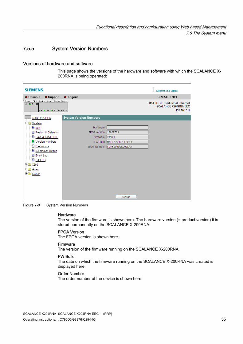
Versions of hardware and software This page shows the versions of the hardware and software with which the SCALANCE X-200RNA is being operated:
Figure 7-8 System Version Numbers
Hardware The version of the firmware is shown here. The hardware version (= product version) it is stored permanently on the SCALANCE X-200RNA.
FPGA Version The FPGA version is shown here.
Firmware The version of the firmware running on the SCALANCE X-200RNA.
FW Build The date on which the firmware running on the SCALANCE X-200RNA was created is displayed here.
Order Number The order number of the device is shown here.
Functional description and configuration using Web based Management 7.5 The System menu
SCALANCE X204RNA SCALANCE X204RNA EEC (PRP) 56 Operating Instructions, , C79000-G8976-C294-03
7.5.6 System Passwords
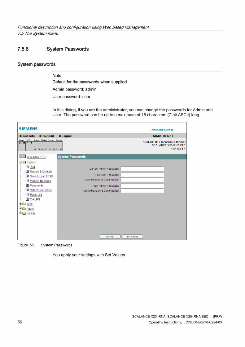
System passwords
Note Default for the passwords when supplied
Admin password: admin
User password: user
In this dialog, if you are the administrator, you can change the passwords for Admin and User. The password can be up to a maximum of 16 characters (7-bit ASCII) long.
Figure 7-9 System Passwords
You apply your settings with Set Values.
Functional description and configuration using Web based Management 7.5 The System menu
SCALANCE X204RNA SCALANCE X204RNA EEC (PRP) Operating Instructions, , C79000-G8976-C294-03 57
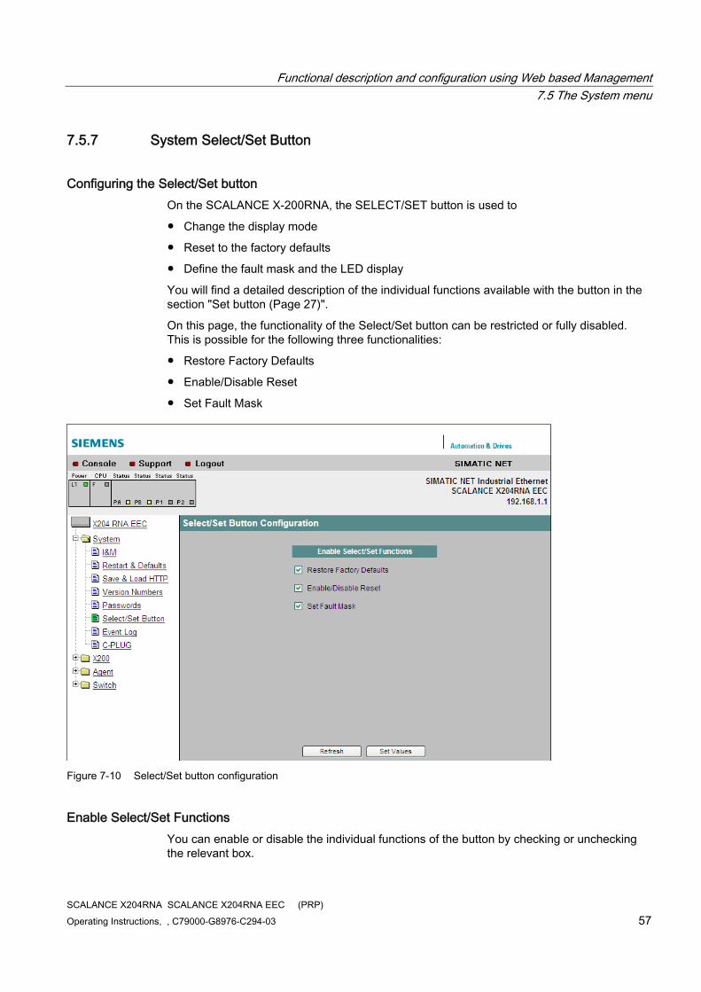
7.5.7 System Select/Set Button
Configuring the Select/Set button On the SCALANCE X-200RNA, the SELECT/SET button is used to
● Change the display mode
● Reset to the factory defaults
● Define the fault mask and the LED display
You will find a detailed description of the individual functions available with the button in the section "Set button (Page 27)".
On this page, the functionality of the Select/Set button can be restricted or fully disabled. This is possible for the following three functionalities:
● Restore Factory Defaults
● Enable/Disable Reset
● Set Fault Mask
Figure 7-10 Select/Set button configuration
Enable Select/Set Functions You can enable or disable the individual functions of the button by checking or unchecking the relevant box.
Functional description and configuration using Web based Management 7.5 The System menu
SCALANCE X204RNA SCALANCE X204RNA EEC (PRP) 58 Operating Instructions, , C79000-G8976-C294-03
You apply your settings with Set Values.
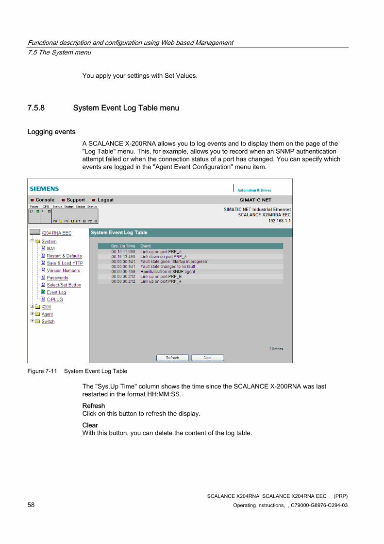
7.5.8 System Event Log Table menu
Logging events A SCALANCE X-200RNA allows you to log events and to display them on the page of the "Log Table" menu. This, for example, allows you to record when an SNMP authentication attempt failed or when the connection status of a port has changed. You can specify which events are logged in the "Agent Event Configuration" menu item.
Figure 7-11 System Event Log Table
The "Sys.Up Time" column shows the time since the SCALANCE X-200RNA was last restarted in the format HH:MM:SS.
Refresh Click on this button to refresh the display.
Clear With this button, you can delete the content of the log table.
Functional description and configuration using Web based Management 7.5 The System menu
SCALANCE X204RNA SCALANCE X204RNA EEC (PRP) Operating Instructions, , C79000-G8976-C294-03 59
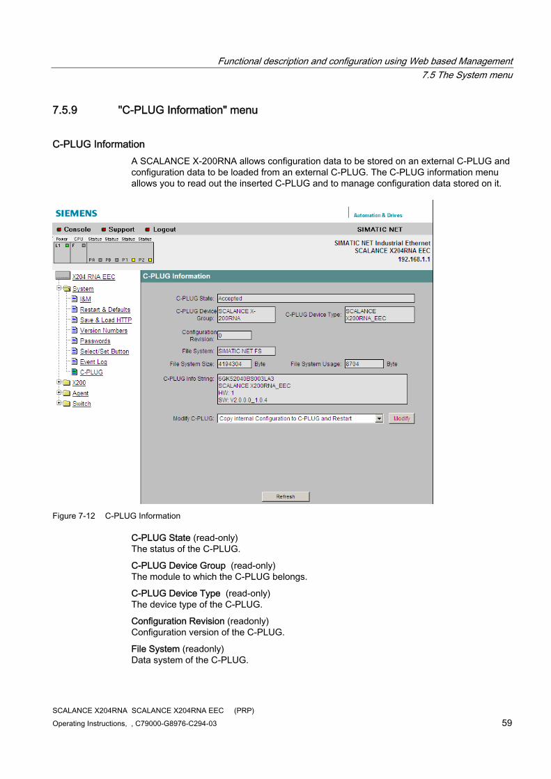
7.5.9 "C-PLUG Information" menu
C-PLUG Information A SCALANCE X-200RNA allows configuration data to be stored on an external C-PLUG and configuration data to be loaded from an external C-PLUG. The C-PLUG information menu allows you to read out the inserted C-PLUG and to manage configuration data stored on it.
Figure 7-12 C-PLUG Information
C-PLUG State (read-only) The status of the C-PLUG.
C-PLUG Device Group (read-only) The module to which the C-PLUG belongs.
C-PLUG Device Type (read-only) The device type of the C-PLUG.
Configuration Revision (readonly) Configuration version of the C-PLUG.
File System (readonly) Data system of the C-PLUG.
Functional description and configuration using Web based Management 7.5 The System menu
SCALANCE X204RNA SCALANCE X204RNA EEC (PRP) 60 Operating Instructions, , C79000-G8976-C294-03
File System Size(readonly) Size of the available data system memory of the C-PLUG.
File System Usage(readonly) Size of the memory of the C-PLUG used by the data system.
C-PLUG Info String (read-only) Information line of the C-PLUG.
Modify C-PLUG Modification of the configuration stored on the C-PLUG.
● Copying the current configuration on the C-PLUG with associated restart
● Copying the factory configuration to the C-PLUG with associated restart
● Deleting the configuration stored on the C-PLUG
Functional description and configuration using Web based Management 7.6 The X200 menu
SCALANCE X204RNA SCALANCE X204RNA EEC (PRP) Operating Instructions, , C79000-G8976-C294-03 61
7.6 The X200 menu
7.6.1 X200 Status
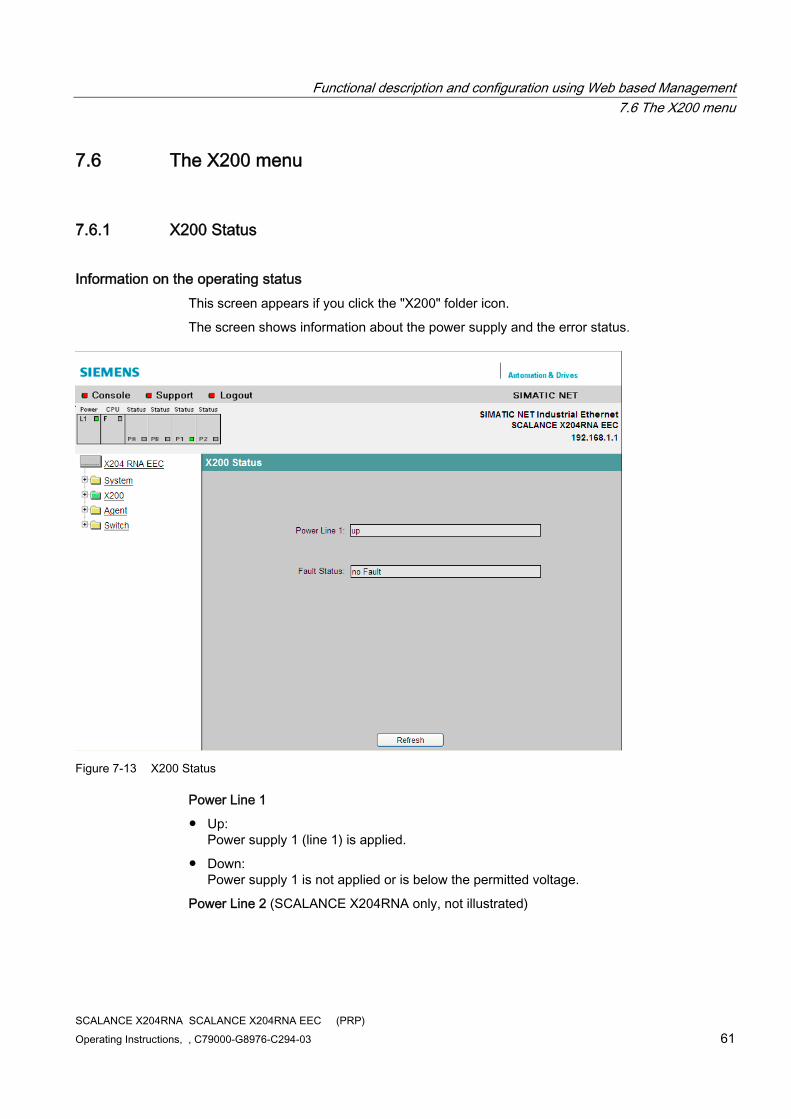
Information on the operating status This screen appears if you click the "X200" folder icon.
The screen shows information about the power supply and the error status.
Figure 7-13 X200 Status
Power Line 1
● Up: Power supply 1 (line 1) is applied.
● Down: Power supply 1 is not applied or is below the permitted voltage.
Power Line 2 (SCALANCE X204RNA only, not illustrated)
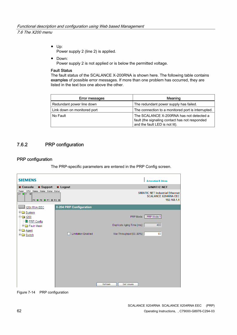
Functional description and configuration using Web based Management 7.6 The X200 menu
SCALANCE X204RNA SCALANCE X204RNA EEC (PRP) 62 Operating Instructions, , C79000-G8976-C294-03
● Up: Power supply 2 (line 2) is applied.
● Down: Power supply 2 is not applied or is below the permitted voltage.
Fault Status The fault status of the SCALANCE X-200RNA is shown here. The following table contains examples of possible error messages. If more than one problem has occurred, they are listed in the text box one above the other.
Error messages Meaning
Redundant power line down The redundant power supply has failed. Link down on monitored port The connection to a monitored port is interrupted. No Fault The SCALANCE X-200RNA has not detected a
fault (the signaling contact has not responded and the fault LED is not lit).
7.6.2 PRP configuration
PRP configuration The PRP-specific parameters are entered in the PRP Config screen.
Figure 7-14 PRP configuration
Functional description and configuration using Web based Management 7.6 The X200 menu
SCALANCE X204RNA SCALANCE X204RNA EEC (PRP) Operating Instructions, , C79000-G8976-C294-03 63
PRP Mode The mode use is PRP (previously "PRP Mode 1"). This value cannot be changed.
Duplicate Aging Time The default value from the PRP standard is 400 ms. This value cannot be changed.
Limitation / Max Throughput By setting the check mark for "Limitation Enabled", the data throughput from the interlinks to the PRP ports is limited to the set value. The limitation can be specified with "Max Throughput". A limitation between 50 and 80% is possible. If the load on the interlinks is greater than the value set, frames are discarded. This occurs regardless of Ethertypes and any VLAN priorities.
7.6.3 Fault Mask
Function of the fault mask With the fault mask, you specify the fault/error states to be monitored by the SCALANCE X-200RNA and that will trigger the signaling contact. Possible fault/error states are the absence of the power supply, power supply too low, or an interrupted connection or an unexpected connection established to a partner device. If the signaling contact is triggered, this causes the fault LED on the device to light up and, depending on the configuration of the event table, can trigger a trap or an entry in the log table.
Device-related link monitoring of the ports A SCALANCE X-200RNA provides device-related link monitoring. A link-up or link-down also affects the message system if the SCALANCE X-200RNA was appropriately configured.
Setting the fault mask on the device Optionally, the fault mask can be set using the SET/SEL button on the SCALANCE X-200RNA. For more detailed information, refer to the section "SET button" (Page 27).
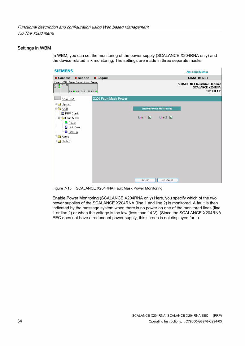
Functional description and configuration using Web based Management 7.6 The X200 menu
SCALANCE X204RNA SCALANCE X204RNA EEC (PRP) 64 Operating Instructions, , C79000-G8976-C294-03
Settings in WBM In WBM, you can set the monitoring of the power supply (SCALANCE X204RNA only) and the device-related link monitoring. The settings are made in three separate masks:
Figure 7-15 SCALANCE X204RNA Fault Mask Power Monitoring
Enable Power Monitoring (SCALANCE X204RNA only) Here, you specify which of the two power supplies of the SCALANCE X204RNA (line 1 and line 2) is monitored. A fault is then indicated by the message system when there is no power on one of the monitored lines (line 1 or line 2) or when the voltage is too low (less than 14 V). (Since the SCALANCE X204RNA EEC does not have a redundant power supply, this screen is not displayed for it).
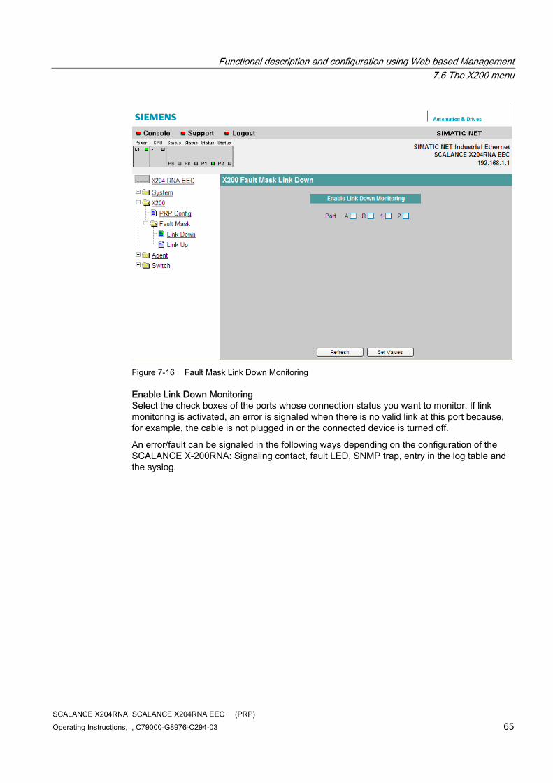
Functional description and configuration using Web based Management 7.6 The X200 menu
SCALANCE X204RNA SCALANCE X204RNA EEC (PRP) Operating Instructions, , C79000-G8976-C294-03 65
Figure 7-16 Fault Mask Link Down Monitoring
Enable Link Down Monitoring Select the check boxes of the ports whose connection status you want to monitor. If link monitoring is activated, an error is signaled when there is no valid link at this port because, for example, the cable is not plugged in or the connected device is turned off.
An error/fault can be signaled in the following ways depending on the configuration of the SCALANCE X-200RNA: Signaling contact, fault LED, SNMP trap, entry in the log table and the syslog.
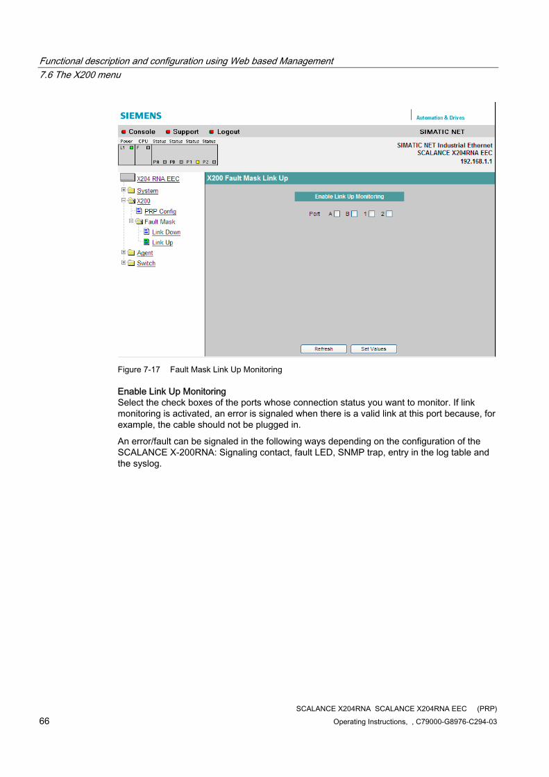
Functional description and configuration using Web based Management 7.6 The X200 menu
SCALANCE X204RNA SCALANCE X204RNA EEC (PRP) 66 Operating Instructions, , C79000-G8976-C294-03
Figure 7-17 Fault Mask Link Up Monitoring
Enable Link Up Monitoring Select the check boxes of the ports whose connection status you want to monitor. If link monitoring is activated, an error is signaled when there is a valid link at this port because, for example, the cable should not be plugged in.
An error/fault can be signaled in the following ways depending on the configuration of the SCALANCE X-200RNA: Signaling contact, fault LED, SNMP trap, entry in the log table and the syslog.
Functional description and configuration using Web based Management 7.7 The Agent menu
SCALANCE X204RNA SCALANCE X204RNA EEC (PRP) Operating Instructions, , C79000-G8976-C294-03 67
7.7 The Agent menu
7.7.1 Agent Configuration
Introduction The "Agent Configuration" screen appears if you click the "Agent" folder icon. This screen provides options for setting the IP address. You can specify whether a SCALANCE X-200RNA obtains the IP address dynamically or you can assign a fixed address.
IP Address
Enter the IP address of the SCALANCE X-200RNA here.
Subnet Mask
Enter the subnet mask of the SCALANCE X-200RNA here.
Note
After changing the IP address, to be able to connect to the SCALANCE X-200RNA again, the new address will need to be entered in the WEB browser manually.
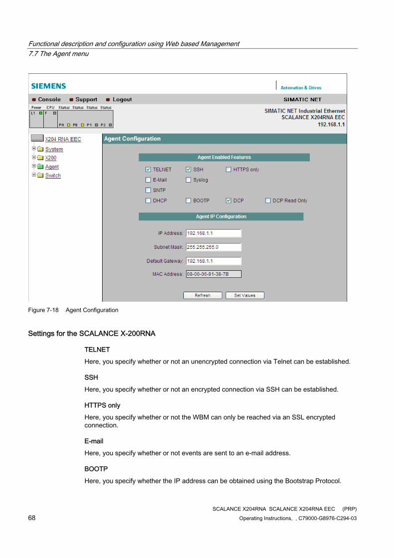
Functional description and configuration using Web based Management 7.7 The Agent menu
SCALANCE X204RNA SCALANCE X204RNA EEC (PRP) 68 Operating Instructions, , C79000-G8976-C294-03
Figure 7-18 Agent Configuration
Settings for the SCALANCE X-200RNA
TELNET
Here, you specify whether or not an unencrypted connection via Telnet can be established.
SSH
Here, you specify whether or not an encrypted connection via SSH can be established.
HTTPS only
Here, you specify whether or not the WBM can only be reached via an SSL encrypted connection.
Here, you specify whether or not events are sent to an e-mail address.
BOOTP
Here, you specify whether the IP address can be obtained using the Bootstrap Protocol.
Functional description and configuration using Web based Management 7.7 The Agent menu
SCALANCE X204RNA SCALANCE X204RNA EEC (PRP) Operating Instructions, , C79000-G8976-C294-03 69
DHCP
Here, you specify whether or not the IP address can be obtained using the Dynamic Host Configuration Protocol.
Syslog
Here, you specify whether or not events are sent to a Syslog server.
DCP
If you select this option, the device can be accessed and configured via DCP (PST Tool and STEP 7).
SNTP
Enables / disables synchronization of the IE switch system time over an SNTP server in the network.
DCP Read Only
If you select this option, the configuration data can only be read via DCP (PST Tool and STEP 7).
Default gateway
If you require the IE switch to communicate with devices (diagnostics stations, e-mail servers, etc.) in a different subnet, you will need to enter the IP address of the default gateway here.
MAC address
The MAC address of the SCALANCE X-200RNA.
7.7.2 Agent Ping
Ping
Configuration of "Ping"
The "Ping" screen appears if you click the "Agent" folder icon. In this screen, you can send a PING to another device in the network to check whether it can be reached.
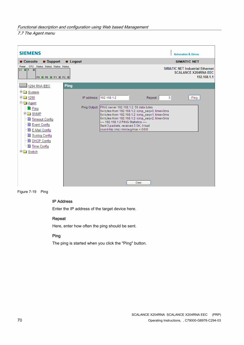
Functional description and configuration using Web based Management 7.7 The Agent menu
SCALANCE X204RNA SCALANCE X204RNA EEC (PRP) 70 Operating Instructions, , C79000-G8976-C294-03
Figure 7-19 Ping
IP Address
Enter the IP address of the target device here.
Repeat
Here, enter how often the ping should be sent.
Ping
The ping is started when you click the "Ping" button.
Functional description and configuration using Web based Management 7.7 The Agent menu
SCALANCE X204RNA SCALANCE X204RNA EEC (PRP) Operating Instructions, , C79000-G8976-C294-03 71
7.7.3 Agent SNMP Configuration
How SNMP works Using SNMP (Simple Network Management Protocol), a network management station can configure and monitor SNMP-compliant nodes, such as a SCALANCE X-200RNA. To allow this, a management agent is installed on the SCALANCE X-200RNA with which the management station exchanges data. There are three frame types:
● Read (management station fetches values from a SCALANCE X-200RNA)
● Write (management station writes values to a SCALANCE X-200RNA)
● Send events to registered nodes (traps). The agent sends messages to registered management stations.
Access permissions with SNMP When using the SNMP protocol, you specify access permissions by means of the community string. A community string contains information about the user name and password in a string. Different community strings are defined for read and write permissions. More complex and more secure authentications are possible only in some SNMPv2 variants and in SNMPv3.
Note
To preserve security, you should not use the default values "public" or "private".
Configuration of SNMP with a SCALANCE X-200RNA The "Agent SNMP Configuration" screen appears if you click the "SNMP" folder icon.
In the SNMP Configuration screen, you make the basic settings for SNMP. Enable the check boxes according to the SNMP functionality you want to use. For detailed settings (for example traps), there are separate menu items in WBM.
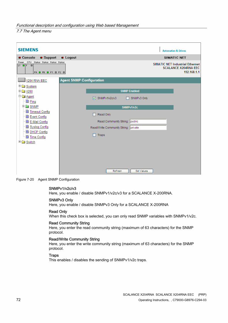
Functional description and configuration using Web based Management 7.7 The Agent menu
SCALANCE X204RNA SCALANCE X204RNA EEC (PRP) 72 Operating Instructions, , C79000-G8976-C294-03
Figure 7-20 Agent SNMP Configuration
SNMPv1/v2c/v3 Here, you enable / disable SNMPv1/v2c/v3 for a SCALANCE X-200RNA.
SNMPv3 Only Here, you enable / disable SNMPv3 Only for a SCALANCE X-200RNA
Read Only When this check box is selected, you can only read SNMP variables with SNMPv1/v2c.
Read Community String Here, you enter the read community string (maximum of 63 characters) for the SNMP protocol.
Read/Write Community String Here, you enter the write community string (maximum of 63 characters) for the SNMP protocol.
Traps This enables / disables the sending of SNMPv1/v2c traps.
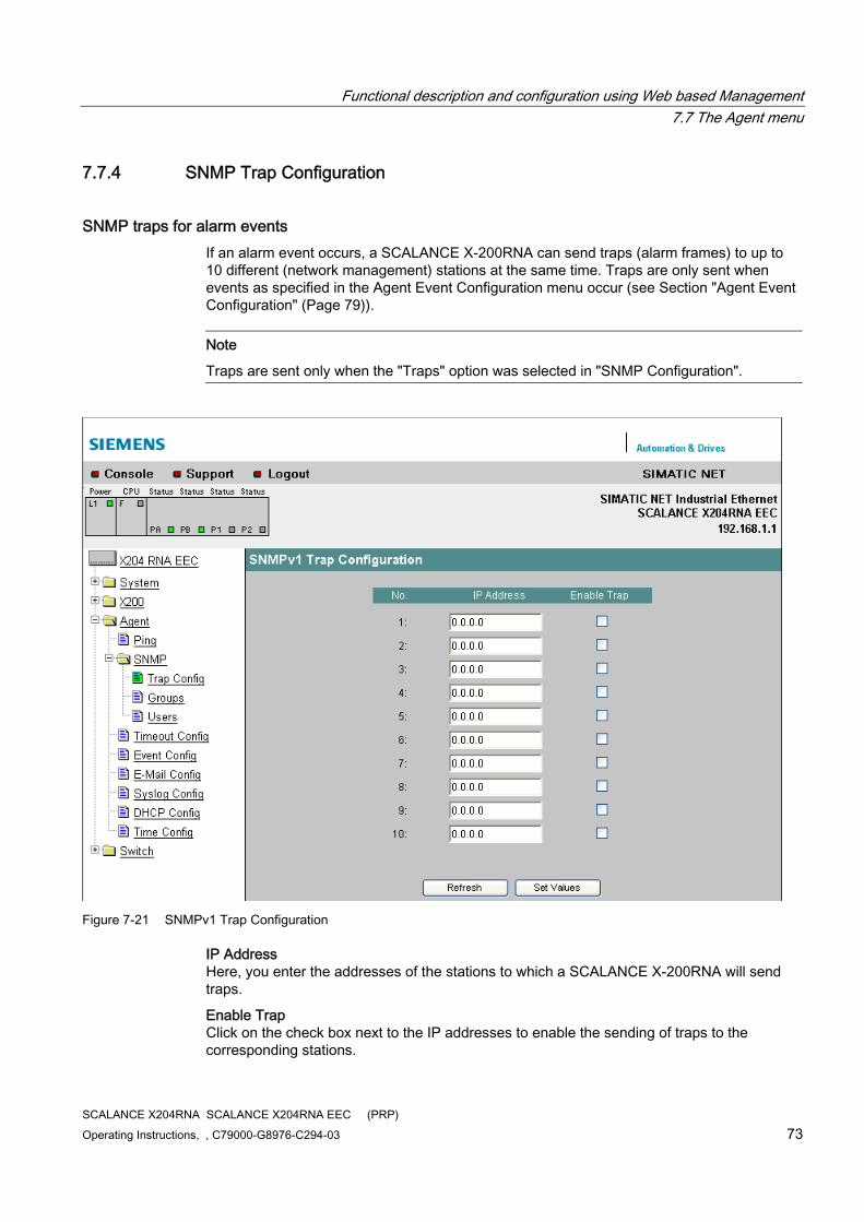
Functional description and configuration using Web based Management 7.7 The Agent menu
SCALANCE X204RNA SCALANCE X204RNA EEC (PRP) Operating Instructions, , C79000-G8976-C294-03 73
7.7.4 SNMP Trap Configuration
SNMP traps for alarm events If an alarm event occurs, a SCALANCE X-200RNA can send traps (alarm frames) to up to 10 different (network management) stations at the same time. Traps are only sent when events as specified in the Agent Event Configuration menu occur (see Section "Agent Event Configuration" (Page 79)).
Note
Traps are sent only when the "Traps" option was selected in "SNMP Configuration".
Figure 7-21 SNMPv1 Trap Configuration
IP Address Here, you enter the addresses of the stations to which a SCALANCE X-200RNA will send traps.
Enable Trap Click on the check box next to the IP addresses to enable the sending of traps to the corresponding stations.
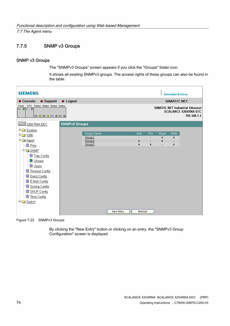
Functional description and configuration using Web based Management 7.7 The Agent menu
SCALANCE X204RNA SCALANCE X204RNA EEC (PRP) 74 Operating Instructions, , C79000-G8976-C294-03
7.7.5 SNMP v3 Groups
SNMP v3 Groups The "SNMPv3 Groups" screen appears if you click the "Groups" folder icon.
It shows all existing SNMPv3 groups. The access rights of these groups can also be found in the table.
Figure 7-22 SNMPv3 Groups
By clicking the "New Entry" button or clicking on an entry, the "SNMPv3 Group Configuration" screen is displayed.
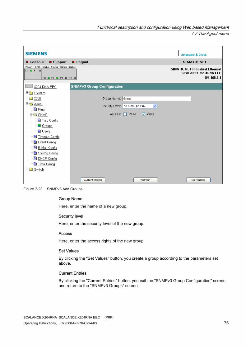
Functional description and configuration using Web based Management 7.7 The Agent menu
SCALANCE X204RNA SCALANCE X204RNA EEC (PRP) Operating Instructions, , C79000-G8976-C294-03 75
Figure 7-23 SNMPv3 Add Groups
Group Name
Here, enter the name of a new group.
Security level
Here, enter the security level of the new group.
Access
Here, enter the access rights of the new group.
Set Values
By clicking the "Set Values" button, you create a group according to the parameters set above.
Current Entries
By clicking the "Current Entries" button, you exit the "SNMPv3 Group Configuration" screen and return to the "SNMPv3 Groups" screen.
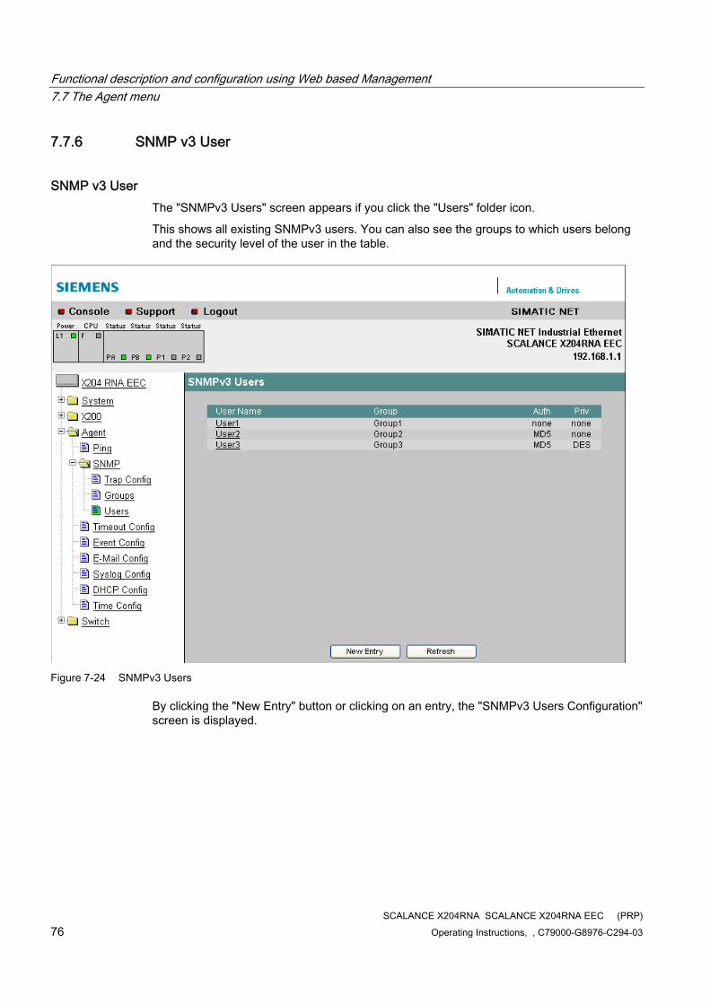
Functional description and configuration using Web based Management 7.7 The Agent menu
SCALANCE X204RNA SCALANCE X204RNA EEC (PRP) 76 Operating Instructions, , C79000-G8976-C294-03
7.7.6 SNMP v3 User
SNMP v3 User The "SNMPv3 Users" screen appears if you click the "Users" folder icon.
This shows all existing SNMPv3 users. You can also see the groups to which users belong and the security level of the user in the table.
Figure 7-24 SNMPv3 Users
By clicking the "New Entry" button or clicking on an entry, the "SNMPv3 Users Configuration" screen is displayed.
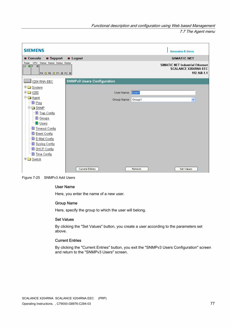
Functional description and configuration using Web based Management 7.7 The Agent menu
SCALANCE X204RNA SCALANCE X204RNA EEC (PRP) Operating Instructions, , C79000-G8976-C294-03 77
Figure 7-25 SNMPv3 Add Users
User Name
Here, you enter the name of a new user.
Group Name
Here, specify the group to which the user will belong.
Set Values
By clicking the "Set Values" button, you create a user according to the parameters set above.
Current Entries
By clicking the "Current Entries" button, you exit the "SNMPv3 Users Configuration" screen and return to the "SNMPv3 Users" screen.
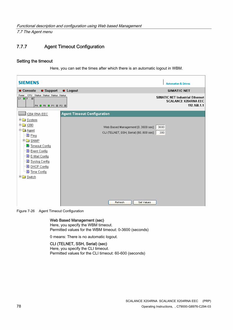
Functional description and configuration using Web based Management 7.7 The Agent menu
SCALANCE X204RNA SCALANCE X204RNA EEC (PRP) 78 Operating Instructions, , C79000-G8976-C294-03
7.7.7 Agent Timeout Configuration
Setting the timeout Here, you can set the times after which there is an automatic logout in WBM.
Figure 7-26 Agent Timeout Configuration
Web Based Management (sec) Here, you specify the WBM timeout. Permitted values for the WBM timeout: 0-3600 (seconds)
0 means: There is no automatic logout.
CLI (TELNET, SSH, Serial) (sec) Here, you specify the CLI timeout. Permitted values for the CLI timeout: 60-600 (seconds)
Functional description and configuration using Web based Management 7.7 The Agent menu
SCALANCE X204RNA SCALANCE X204RNA EEC (PRP) Operating Instructions, , C79000-G8976-C294-03 79
7.7.8 Agent Event Configuration
System events of the SCALANCE X-200RNA On this page, you specify how a SCALANCE X-200RNA reacts to system events. By enabling the appropriate check boxes, you specify which events trigger which reactions on the SCALANCE X-200RNA. The following options are available:
● The SCALANCE X-200RNA sends an e-mail with the error message
● The SCALANCE X-200RNA triggers an SNMP trap.
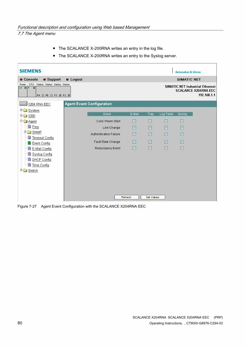
Functional description and configuration using Web based Management 7.7 The Agent menu
SCALANCE X204RNA SCALANCE X204RNA EEC (PRP) 80 Operating Instructions, , C79000-G8976-C294-03
● The SCALANCE X-200RNA writes an entry in the log file.
● The SCALANCE X-200RNA writes an entry to the Syslog server.
Figure 7-27 Agent Event Configuration with the SCALANCE X204RNA EEC
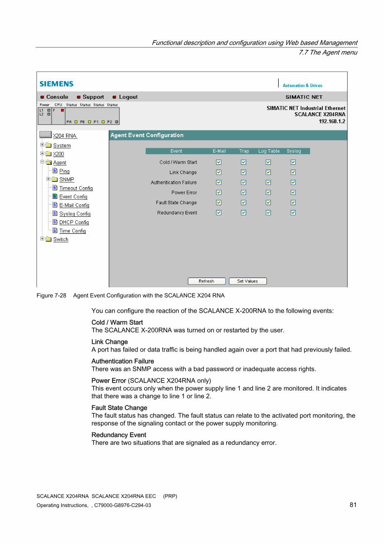
Functional description and configuration using Web based Management 7.7 The Agent menu
SCALANCE X204RNA SCALANCE X204RNA EEC (PRP) Operating Instructions, , C79000-G8976-C294-03 81
Figure 7-28 Agent Event Configuration with the SCALANCE X204 RNA
You can configure the reaction of the SCALANCE X-200RNA to the following events:
Cold / Warm Start The SCALANCE X-200RNA was turned on or restarted by the user.
Link Change A port has failed or data traffic is being handled again over a port that had previously failed.
Authentication Failure There was an SNMP access with a bad password or inadequate access rights.
Power Error (SCALANCE X204RNA only) This event occurs only when the power supply line 1 and line 2 are monitored. It indicates that there was a change to line 1 or line 2.
Fault State Change The fault status has changed. The fault status can relate to the activated port monitoring, the response of the signaling contact or the power supply monitoring.
Redundancy Event There are two situations that are signaled as a redundancy error.
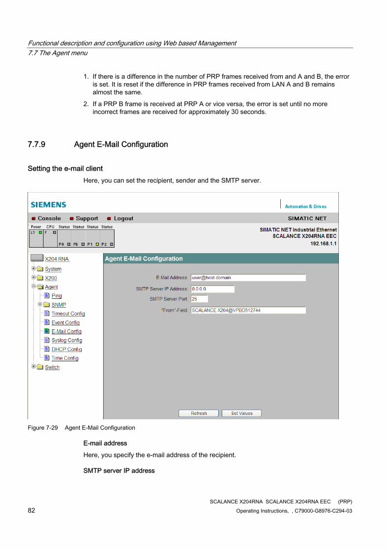
Functional description and configuration using Web based Management 7.7 The Agent menu
SCALANCE X204RNA SCALANCE X204RNA EEC (PRP) 82 Operating Instructions, , C79000-G8976-C294-03
1. If there is a difference in the number of PRP frames received from and A and B, the error is set. It is reset if the difference in PRP frames received from LAN A and B remains almost the same.
2. If a PRP B frame is received at PRP A or vice versa, the error is set until no more incorrect frames are received for approximately 30 seconds.
7.7.9 Agent E-Mail Configuration
Setting the e-mail client Here, you can set the recipient, sender and the SMTP server.
Figure 7-29 Agent E-Mail Configuration
E-mail address
Here, you specify the e-mail address of the recipient.
SMTP server IP address
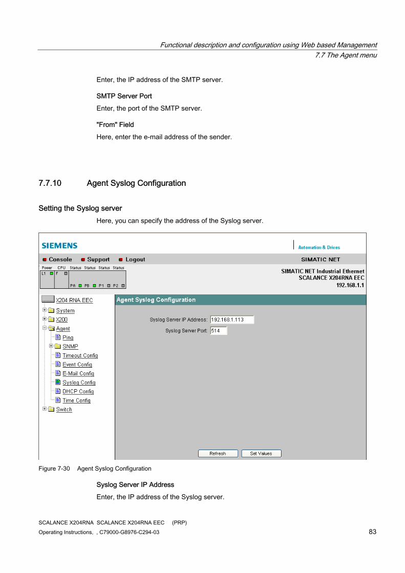
Functional description and configuration using Web based Management 7.7 The Agent menu
SCALANCE X204RNA SCALANCE X204RNA EEC (PRP) Operating Instructions, , C79000-G8976-C294-03 83
Enter, the IP address of the SMTP server.
SMTP Server Port
Enter, the port of the SMTP server.
"From" Field
Here, enter the e-mail address of the sender.
7.7.10 Agent Syslog Configuration
Setting the Syslog server Here, you can specify the address of the Syslog server.
Figure 7-30 Agent Syslog Configuration
Syslog Server IP Address
Enter, the IP address of the Syslog server.
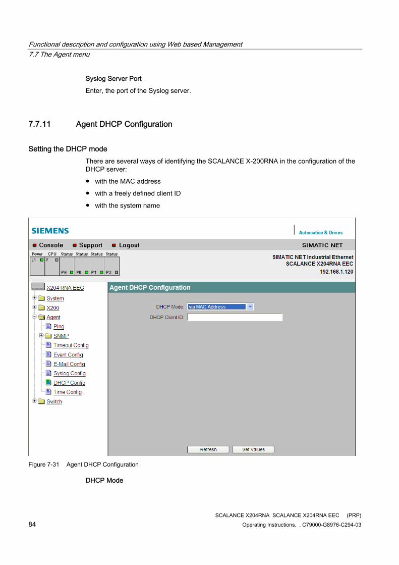
Functional description and configuration using Web based Management 7.7 The Agent menu
SCALANCE X204RNA SCALANCE X204RNA EEC (PRP) 84 Operating Instructions, , C79000-G8976-C294-03
Syslog Server Port
Enter, the port of the Syslog server.
7.7.11 Agent DHCP Configuration
Setting the DHCP mode There are several ways of identifying the SCALANCE X-200RNA in the configuration of the DHCP server:
● with the MAC address
● with a freely defined client ID
● with the system name
Figure 7-31 Agent DHCP Configuration
DHCP Mode
Functional description and configuration using Web based Management 7.7 The Agent menu
SCALANCE X204RNA SCALANCE X204RNA EEC (PRP) Operating Instructions, , C79000-G8976-C294-03 85
Here, you set the DHCP mode.
Note
If DHCP is not enabled in the "Agent Configuration" menu item, no mode can be selected and the text "disabled" is displayed.
DHCP client ID
For the DHCP mode "via Client ID", you can assign an identification string here that is assigned to a SCALANCE X-200RNA and will be evaluated by the DHCP server.
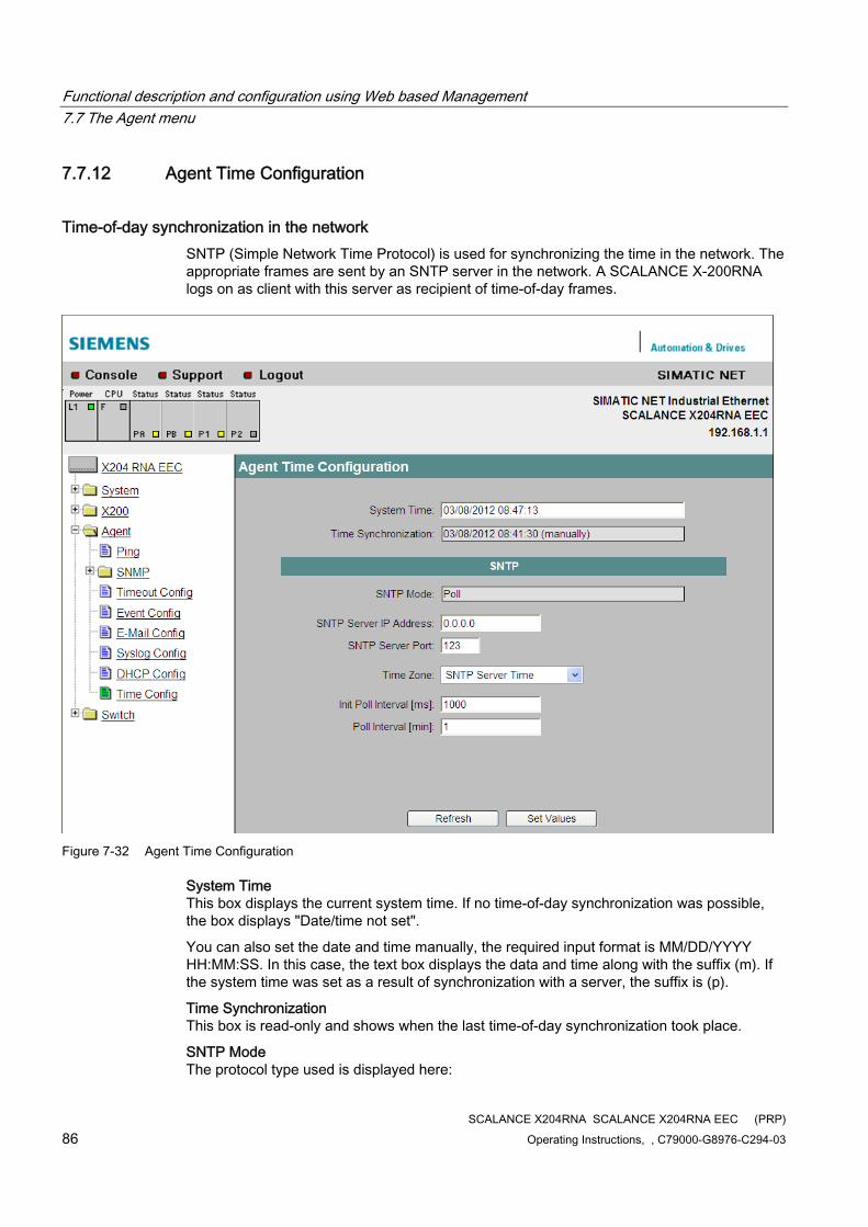
Functional description and configuration using Web based Management 7.7 The Agent menu
SCALANCE X204RNA SCALANCE X204RNA EEC (PRP) 86 Operating Instructions, , C79000-G8976-C294-03
7.7.12 Agent Time Configuration
Time-of-day synchronization in the network SNTP (Simple Network Time Protocol) is used for synchronizing the time in the network. The appropriate frames are sent by an SNTP server in the network. A SCALANCE X-200RNA logs on as client with this server as recipient of time-of-day frames.
Figure 7-32 Agent Time Configuration
System Time This box displays the current system time. If no time-of-day synchronization was possible, the box displays "Date/time not set".
You can also set the date and time manually, the required input format is MM/DD/YYYY HH:MM:SS. In this case, the text box displays the data and time along with the suffix (m). If the system time was set as a result of synchronization with a server, the suffix is (p).
Time Synchronization This box is read-only and shows when the last time-of-day synchronization took place.
SNTP Mode The protocol type used is displayed here:
Functional description and configuration using Web based Management 7.7 The Agent menu
SCALANCE X204RNA SCALANCE X204RNA EEC (PRP) Operating Instructions, , C79000-G8976-C294-03 87
● Poll If you choose this protocol type, you have to define further settings: Time zone offset, Time server, Init poll interval, Poll interval.
SNTP Server IP Address Here, you enter the IP address of the SNTP server whose frames will be used by a SCALANCE X-200RNA to synchronize the time of day.
SNTP Server Port Here, enter the port over which the SNTP server is available.
Time Zone Select the time zone for the location of the SCALANCE X-200RNA because the SNTP server always sends UTC time. This time is then recalculated and displayed as the local time based on the time zone. There is no standard/daylight-saving time switchover on the SCALANCE X-200RNA.
Init poll interval Here, you can enter the interval at which a SCALANCE X-200RNA repeats the initial poll for the system time if this was not successful the first time.
Poll interval Once the system time has been adopted the first time from the time server, it is updated cyclically with renewed polls to the time server. Here, you specify how often the updates take place.
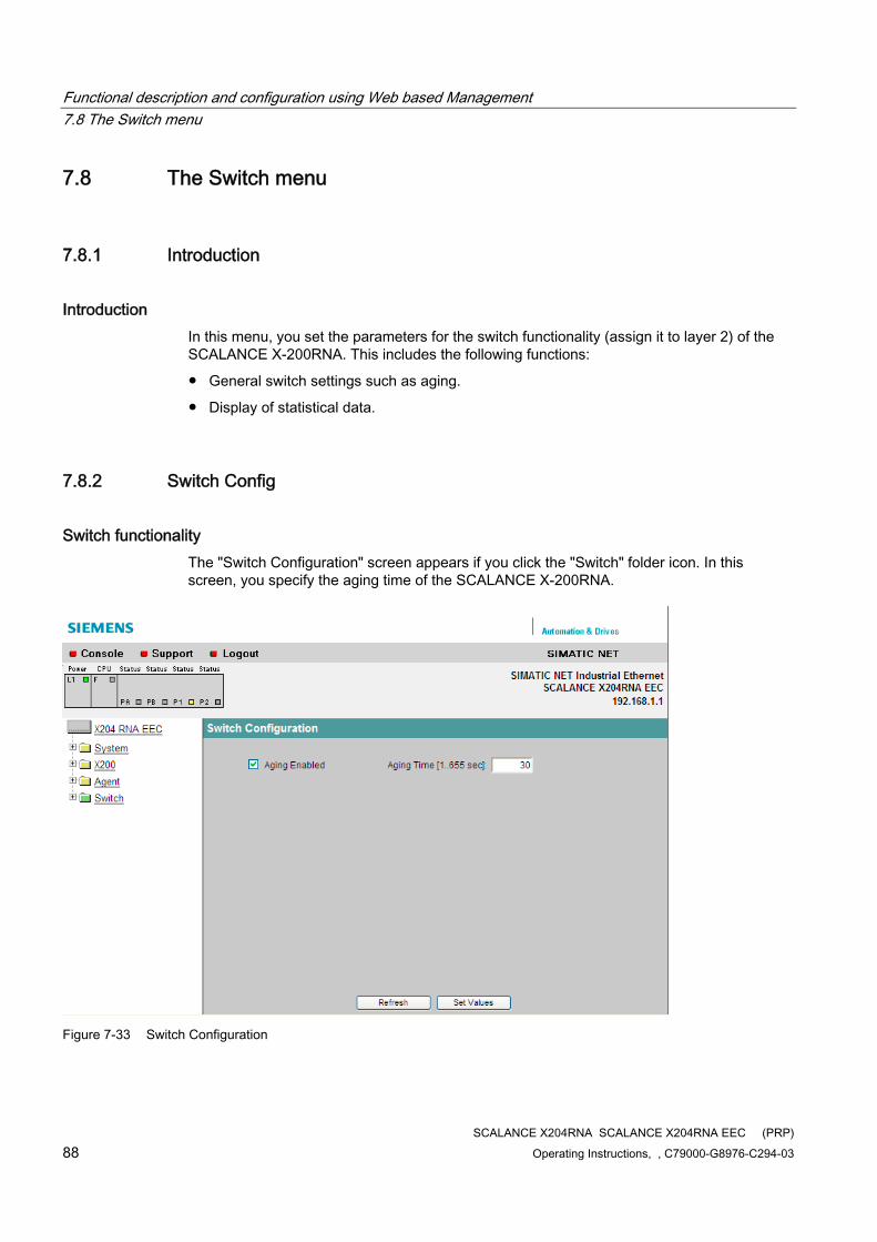
Functional description and configuration using Web based Management 7.8 The Switch menu
SCALANCE X204RNA SCALANCE X204RNA EEC (PRP) 88 Operating Instructions, , C79000-G8976-C294-03
7.8 The Switch menu
7.8.1 Introduction
Introduction In this menu, you set the parameters for the switch functionality (assign it to layer 2) of the SCALANCE X-200RNA. This includes the following functions:
● General switch settings such as aging.
● Display of statistical data.
7.8.2 Switch Config
Switch functionality The "Switch Configuration" screen appears if you click the "Switch" folder icon. In this screen, you specify the aging time of the SCALANCE X-200RNA.
Figure 7-33 Switch Configuration
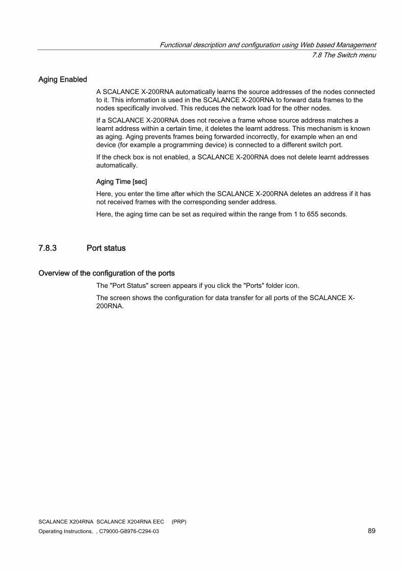
Functional description and configuration using Web based Management 7.8 The Switch menu
SCALANCE X204RNA SCALANCE X204RNA EEC (PRP) Operating Instructions, , C79000-G8976-C294-03 89
Aging Enabled A SCALANCE X-200RNA automatically learns the source addresses of the nodes connected to it. This information is used in the SCALANCE X-200RNA to forward data frames to the nodes specifically involved. This reduces the network load for the other nodes.
If a SCALANCE X-200RNA does not receive a frame whose source address matches a learnt address within a certain time, it deletes the learnt address. This mechanism is known as aging. Aging prevents frames being forwarded incorrectly, for example when an end device (for example a programming device) is connected to a different switch port.
If the check box is not enabled, a SCALANCE X-200RNA does not delete learnt addresses automatically.
Aging Time [sec]
Here, you enter the time after which the SCALANCE X-200RNA deletes an address if it has not received frames with the corresponding sender address.
Here, the aging time can be set as required within the range from 1 to 655 seconds.
7.8.3 Port status
Overview of the configuration of the ports The "Port Status" screen appears if you click the "Ports" folder icon.
The screen shows the configuration for data transfer for all ports of the SCALANCE X-200RNA.
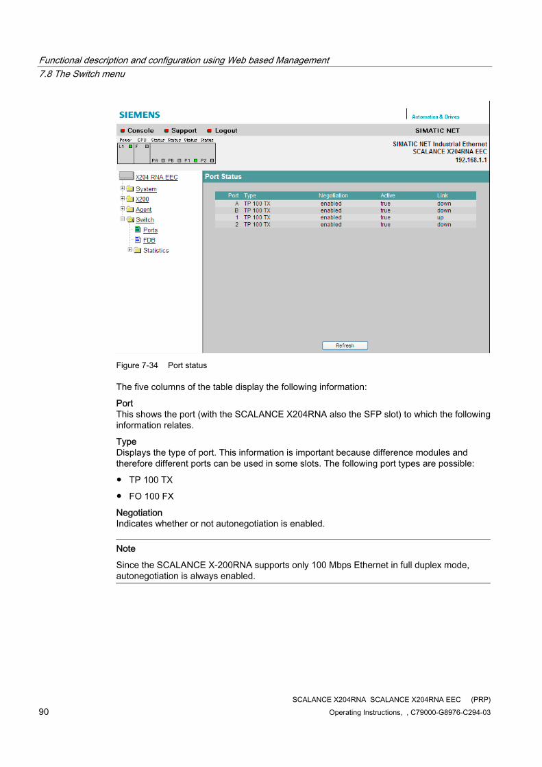
Functional description and configuration using Web based Management 7.8 The Switch menu
SCALANCE X204RNA SCALANCE X204RNA EEC (PRP) 90 Operating Instructions, , C79000-G8976-C294-03
Figure 7-34 Port status
The five columns of the table display the following information:
Port This shows the port (with the SCALANCE X204RNA also the SFP slot) to which the following information relates.
Type Displays the type of port. This information is important because difference modules and therefore different ports can be used in some slots. The following port types are possible:
● TP 100 TX
● FO 100 FX
Negotiation Indicates whether or not autonegotiation is enabled.
Note
Since the SCALANCE X-200RNA supports only 100 Mbps Ethernet in full duplex mode, autonegotiation is always enabled.
Functional description and configuration using Web based Management 7.8 The Switch menu
SCALANCE X204RNA SCALANCE X204RNA EEC (PRP) Operating Instructions, , C79000-G8976-C294-03 91
Active Indicates whether or not the port is turned on (true). Data traffic is possible only over an enabled port.
Note
With the SCALANCE X-200RNA, the ports cannot be turned off.
Link Shows the connection status to the network. The available options are as follows:
● Up The port has a valid link to the network, a link integrity signal is being received.
● Down The link is down, for example because the connected device is turned off.
7.8.4 Switch Forwarding Database
Display of the Switch Forwarding Database The "Switch Forwarding Database" screen appears if you click the "FDB" folder icon.
The screen shows the dynamically learnt MAC addresses in the FDB table for all ports. In addition to this, to allow PRP diagnostics, the screen also shows whether the displayed MAC addresses are listed in the duplicate filter or in the proxy node table.
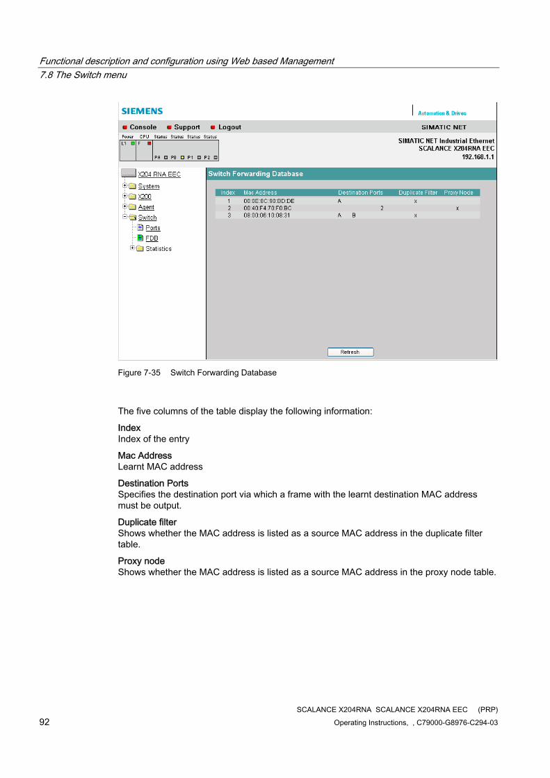
Functional description and configuration using Web based Management 7.8 The Switch menu
SCALANCE X204RNA SCALANCE X204RNA EEC (PRP) 92 Operating Instructions, , C79000-G8976-C294-03
Figure 7-35 Switch Forwarding Database
The five columns of the table display the following information:
Index Index of the entry
Mac Address Learnt MAC address
Destination Ports Specifies the destination port via which a frame with the learnt destination MAC address must be output.
Duplicate filter Shows whether the MAC address is listed as a source MAC address in the duplicate filter table.
Proxy node Shows whether the MAC address is listed as a source MAC address in the proxy node table.

Functional description and configuration using Web based Management 7.8 The Switch menu
SCALANCE X204RNA SCALANCE X204RNA EEC (PRP) Operating Instructions, , C79000-G8976-C294-03 93
7.8.5 the Statistics menu
Counting and evaluation of received frames A SCALANCE X-204RNA has internal statistics counters with which it counts the number of received frames for each port according to the following criteria:
● Frame length
● Message frame type
● Bad frames
This information provides you with an overview of the data traffic and any problems on the network.
7.8.6 Packet Size Statistic
Received frames sorted by length The "Packet Size Statistics" page displays how many packets of which size were received at each port.
If you click the "Reset Counters" button, you reset the counters for all ports.
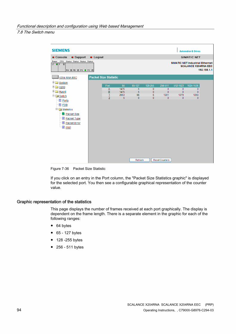
Functional description and configuration using Web based Management 7.8 The Switch menu
SCALANCE X204RNA SCALANCE X204RNA EEC (PRP) 94 Operating Instructions, , C79000-G8976-C294-03
Figure 7-36 Packet Size Statistic
If you click on an entry in the Port column, the "Packet Size Statistics graphic" is displayed for the selected port. You then see a configurable graphical representation of the counter value.
Graphic representation of the statistics This page displays the number of frames received at each port graphically. The display is dependent on the frame length. There is a separate element in the graphic for each of the following ranges:
● 64 bytes
● 65 - 127 bytes
● 128 -255 bytes
● 256 - 511 bytes
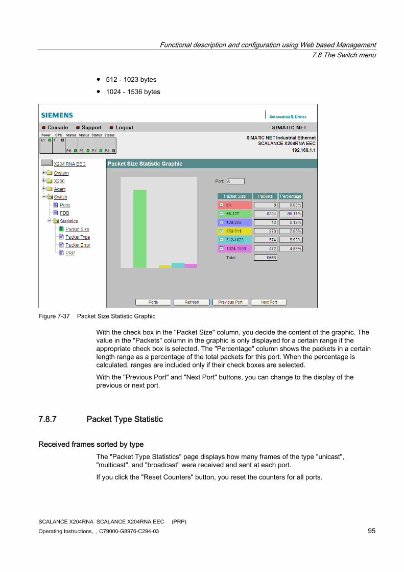
Functional description and configuration using Web based Management 7.8 The Switch menu
SCALANCE X204RNA SCALANCE X204RNA EEC (PRP) Operating Instructions, , C79000-G8976-C294-03 95
● 512 - 1023 bytes
● 1024 - 1536 bytes
Figure 7-37 Packet Size Statistic Graphic
With the check box in the "Packet Size" column, you decide the content of the graphic. The value in the "Packets" column in the graphic is only displayed for a certain range if the appropriate check box is selected. The "Percentage" column shows the packets in a certain length range as a percentage of the total packets for this port. When the percentage is calculated, ranges are included only if their check boxes are selected.
With the "Previous Port" and "Next Port" buttons, you can change to the display of the previous or next port.
7.8.7 Packet Type Statistic
Received frames sorted by type The "Packet Type Statistics" page displays how many frames of the type "unicast", "multicast", and "broadcast" were received and sent at each port.
If you click the "Reset Counters" button, you reset the counters for all ports.
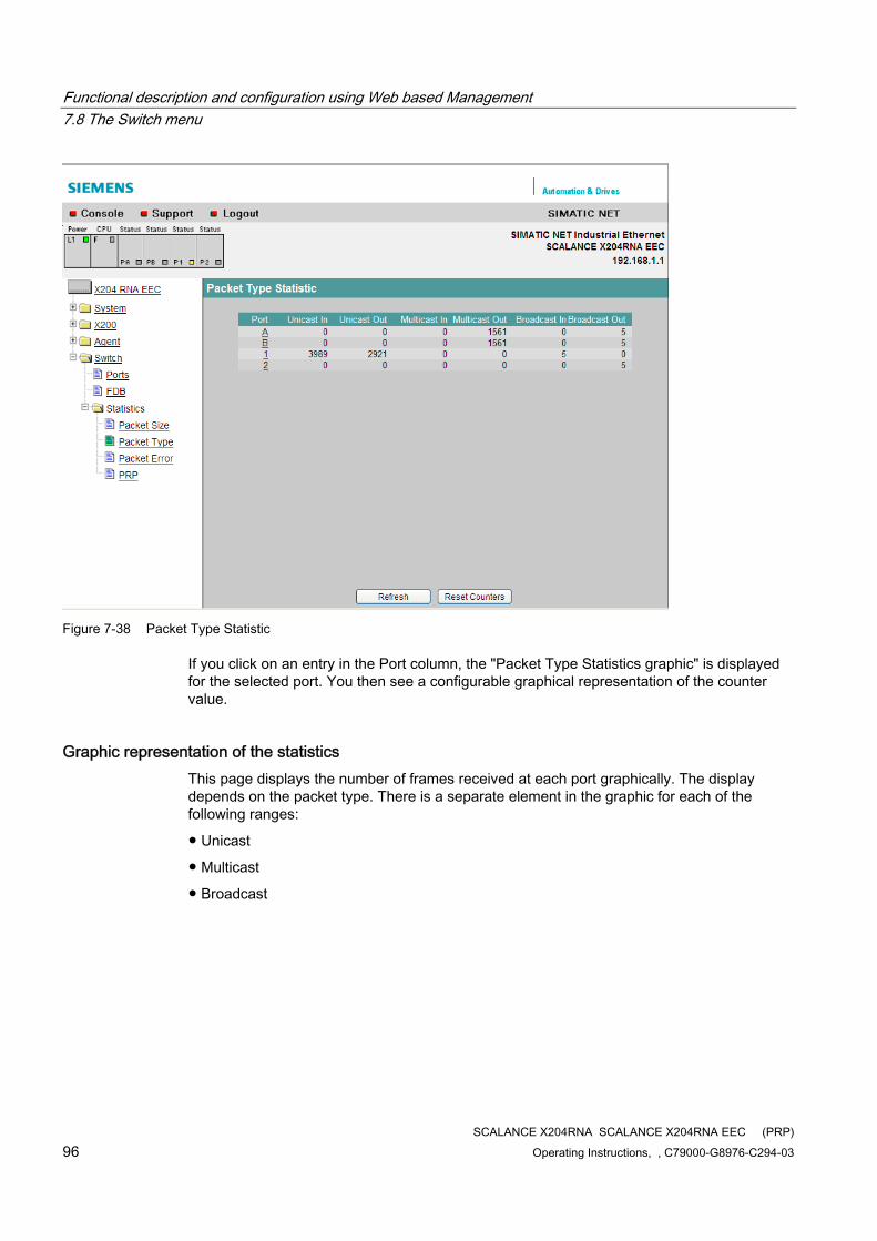
Functional description and configuration using Web based Management 7.8 The Switch menu
SCALANCE X204RNA SCALANCE X204RNA EEC (PRP) 96 Operating Instructions, , C79000-G8976-C294-03
Figure 7-38 Packet Type Statistic
If you click on an entry in the Port column, the "Packet Type Statistics graphic" is displayed for the selected port. You then see a configurable graphical representation of the counter value.
Graphic representation of the statistics This page displays the number of frames received at each port graphically. The display depends on the packet type. There is a separate element in the graphic for each of the following ranges:
● Unicast
● Multicast
● Broadcast
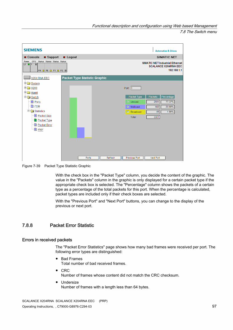
Functional description and configuration using Web based Management 7.8 The Switch menu
SCALANCE X204RNA SCALANCE X204RNA EEC (PRP) Operating Instructions, , C79000-G8976-C294-03 97
Figure 7-39 Packet Type Statistic Graphic
With the check box in the "Packet Type" column, you decide the content of the graphic. The value in the "Packets" column in the graphic is only displayed for a certain packet type if the appropriate check box is selected. The "Percentage" column shows the packets of a certain type as a percentage of the total packets for this port. When the percentage is calculated, packet types are included only if their check boxes are selected.
With the "Previous Port" and "Next Port" buttons, you can change to the display of the previous or next port.
7.8.8 Packet Error Statistic
Errors in received packets The "Packet Error Statistics" page shows how many bad frames were received per port. The following error types are distinguished:
● Bad Frames Total number of bad received frames.
● CRC Number of frames whose content did not match the CRC checksum.
● Undersize Number of frames with a length less than 64 bytes.
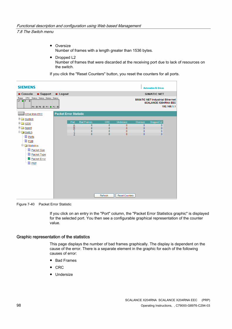
Functional description and configuration using Web based Management 7.8 The Switch menu
SCALANCE X204RNA SCALANCE X204RNA EEC (PRP) 98 Operating Instructions, , C79000-G8976-C294-03
● Oversize Number of frames with a length greater than 1536 bytes.
● Dropped L2 Number of frames that were discarded at the receiving port due to lack of resources on the switch.
If you click the "Reset Counters" button, you reset the counters for all ports.
Figure 7-40 Packet Error Statistic
If you click on an entry in the "Port" column, the "Packet Error Statistics graphic" is displayed for the selected port. You then see a configurable graphical representation of the counter value.
Graphic representation of the statistics This page displays the number of bad frames graphically. The display is dependent on the cause of the error. There is a separate element in the graphic for each of the following causes of error:
● Bad Frames
● CRC
● Undersize
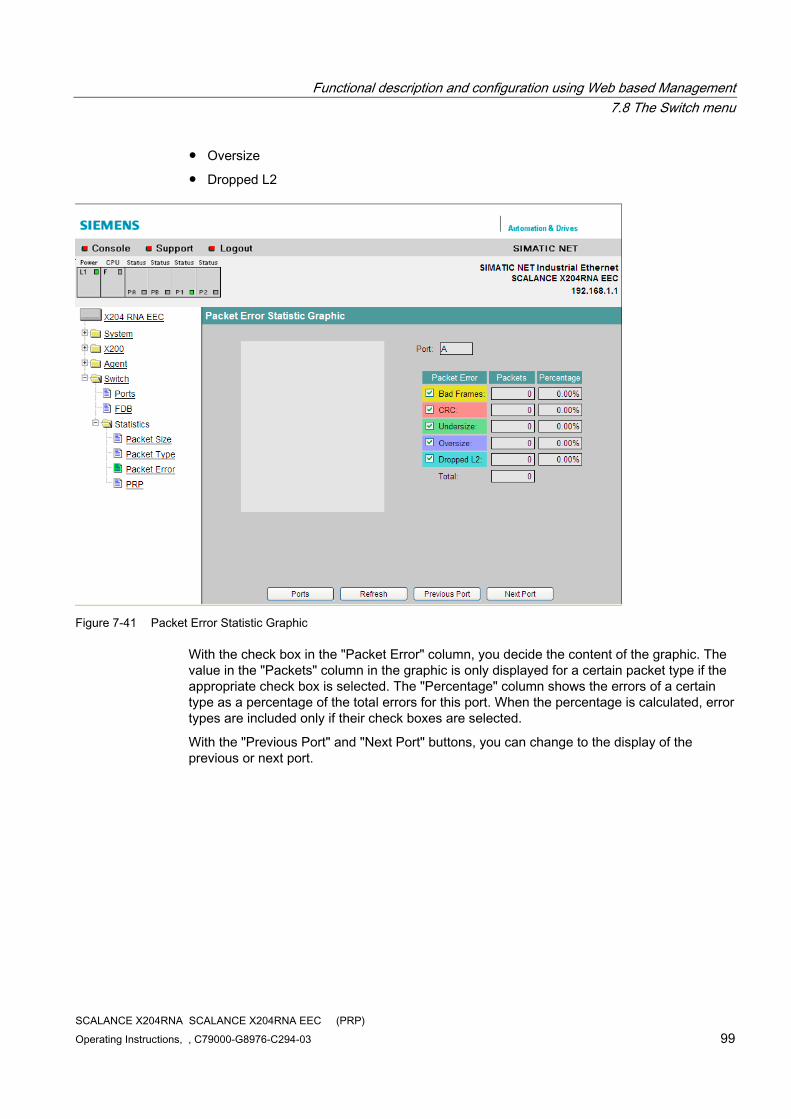
Functional description and configuration using Web based Management 7.8 The Switch menu
SCALANCE X204RNA SCALANCE X204RNA EEC (PRP) Operating Instructions, , C79000-G8976-C294-03 99
● Oversize
● Dropped L2
Figure 7-41 Packet Error Statistic Graphic
With the check box in the "Packet Error" column, you decide the content of the graphic. The value in the "Packets" column in the graphic is only displayed for a certain packet type if the appropriate check box is selected. The "Percentage" column shows the errors of a certain type as a percentage of the total errors for this port. When the percentage is calculated, error types are included only if their check boxes are selected.
With the "Previous Port" and "Next Port" buttons, you can change to the display of the previous or next port.
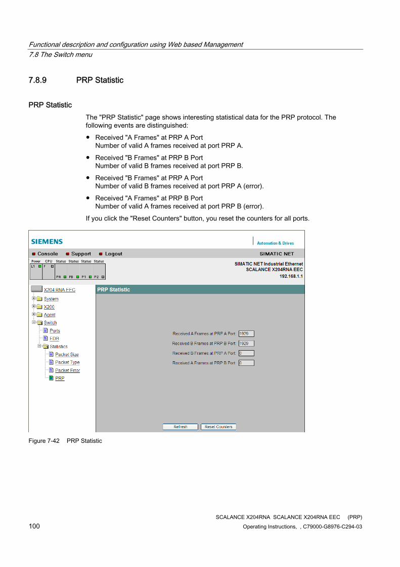
Functional description and configuration using Web based Management 7.8 The Switch menu
SCALANCE X204RNA SCALANCE X204RNA EEC (PRP) 100 Operating Instructions, , C79000-G8976-C294-03
7.8.9 PRP Statistic
PRP Statistic The "PRP Statistic" page shows interesting statistical data for the PRP protocol. The following events are distinguished:
● Received "A Frames" at PRP A Port Number of valid A frames received at port PRP A.
● Received "B Frames" at PRP B Port Number of valid B frames received at port PRP B.
● Received "B Frames" at PRP A Port Number of valid B frames received at port PRP A (error).
● Received "A Frames" at PRP B Port Number of valid A frames received at port PRP B (error).
If you click the "Reset Counters" button, you reset the counters for all ports.
Figure 7-42 PRP Statistic
SCALANCE X204RNA SCALANCE X204RNA EEC (PRP) Operating Instructions, , C79000-G8976-C294-03 101
Approvals and marking 88.1 Approvals and marking
Approvals and marking
Note
The specified approvals apply only when the corresponding mark is printed on the product. You can check which of the following approvals have been granted for your product by the markings on the type plate.
Product name
Type designation Order number SCALANCE X204RNA 6GK5204-0BA00-2KB2 SCALANCE X204RNA EEC 6GK5204-0BS00-3LA3
EC directives SIMATIC NET products meet the requirements and aims of the following EC directives.
Conformity certificates You will find the EC Declaration of Conformity for this product on the Internet at the following address:
(http://support.automation.siemens.com/WW/view/de/52323714/133400)
→ Entry list
→ Entry type "Certificates"
→ Type of certificate "Declaration of conformity"
Example German: "EG Konformitätserklärung SCALANCE X204RNA",
Example English: "Declaration of Conformity SCALANCE X204RNA ".
EMC directive (electromagnetic compatibility) The SCALANCE X-200RNA devices meet the requirements of the EC directive:
2004/108/EEC "Electromagnetic Compatibility"
Approvals and marking 8.1 Approvals and marking
SCALANCE X204RNA SCALANCE X204RNA EEC (PRP) 102 Operating Instructions, , C79000-G8976-C294-03
The product is designed for use in the following areas:
Area of application
RF interference level Immunity to interference Industry EN 61000 6 4: 2007 EN 61000 6 2: 2005
WARNING Personal injury and damage to property may occur.
The installation of expansions that are not approved for SIMATIC NET products or their target systems may violate the requirements and regulations for safety and electromagnetic compatibility.
Only use expansions that are approved for the system.
● Keep to the installation guidelines The product meets the requirements if you adhere to the installation and safety instructions contained in this documentation and in the following documentation when installing and operating the product.
● You can always find the latest documentation on the Internet! The current descriptions of the currently available products can always be found on the Internet under the specified Internet pages:
– SIMATIC NET Industrial Twisted Pair and Fiber Optic Networks (http://support.automation.siemens.com/WW/view/en/8763736/) , Manual
– EMC Installation Guideline (http://support.automation.siemens.com/WW/view/en/60612658) , Configuration manual
● Working on the product To protect the product from electrostatic discharge, personnel must first discharge any electrostatic charge from their body before touching the product.
Note
The product was tested with a device that also complies with the standards listed above.
When operating the product with a device that does not comply with these standards, adherence to the corresponding values cannot be guaranteed.
Explosion protection directive (ATEX) The SCALANCE X204RNA device meets the requirements of the EC directive:
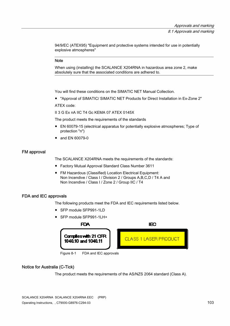
Approvals and marking 8.1 Approvals and marking
SCALANCE X204RNA SCALANCE X204RNA EEC (PRP) Operating Instructions, , C79000-G8976-C294-03 103
94/9/EC (ATEX95) "Equipment and protective systems intended for use in potentially explosive atmospheres"
Note
When using (installing) the SCALANCE X204RNA in hazardous area zone 2, make absolutely sure that the associated conditions are adhered to.
You will find these conditions on the SIMATIC NET Manual Collection.
● "Approval of SIMATIC/ SIMATIC NET Products for Direct Installation in Ex-Zone 2"
ATEX code:
II 3 G Ex nA IIC T4 Gc KEMA 07 ATEX 0145X
The product meets the requirements of the standards
● EN 60079-15 (electrical apparatus for potentially explosive atmospheres; Type of protection "n")
● and EN 60079-0
FM approval The SCALANCE X204RNA meets the requirements of the standards:
● Factory Mutual Approval Standard Class Number 3611
● FM Hazardous (Classified) Location Electrical Equipment: Non Incendive / Class I / Division 2 / Groups A,B,C,D / T4 A and Non Incendive / Class I / Zone 2 / Group IIC / T4
FDA and IEC approvals The following products meet the FDA and IEC requirements listed below.
● SFP module SFP991-1LD
● SFP module SFP991-1LH+
Figure 8-1 FDA and IEC approvals
Notice for Australia (C-Tick) The product meets the requirements of the AS/NZS 2064 standard (Class A).

Approvals and marking 8.1 Approvals and marking
SCALANCE X204RNA SCALANCE X204RNA EEC (PRP) 104 Operating Instructions, , C79000-G8976-C294-03
Notice for Korea (Kc) The product meets the requirements of the Korea Certification.
UL Approval for Information Technology Equipment Underwriters Laboratories (UL) complying with Standard UL 60950-1
UL Approval for Industrial Control Equipment Underwriters Laboratories (UL) complying with Standard UL 508
For use in Pollution Degree 2 Environment
CSA Approval for Information Technology Equipment CSA Certification Mark
Canadian Standard Association CSA C22.2 No. 60950-1-03
CSA Approval for Industrial Control Equipment CSA Certification Mark
Canadian Standard Association CSA C22.2 No. 142-M1987
cULus Approval for Information Technology Equipment Underwriters Laboratories Inc. complying with
● UL 60950-1 (Information Technology Equipment)
● CSA C22.2 No. 60950-1-03
cULus Approval for Industrial Control Equipment Underwriters Laboratories Inc. complying with
● UL 508
● CSA C22.2 No. 142-M1987
For use in Pollution Degree 2 Environment
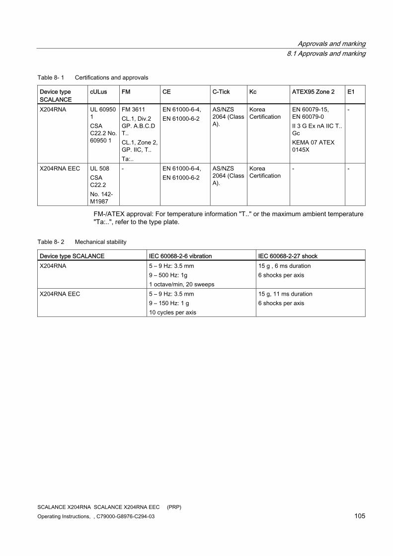
Approvals and marking 8.1 Approvals and marking
SCALANCE X204RNA SCALANCE X204RNA EEC (PRP) Operating Instructions, , C79000-G8976-C294-03 105
Table 8- 1 Certifications and approvals
Device type SCALANCE
cULus FM CE C-Tick Kc ATEX95 Zone 2 E1
X204RNA UL 60950 1 CSA C22.2 No. 60950 1
FM 3611 CL.1, Div.2 GP. A.B.C.D T.. CL.1, Zone 2, GP. IIC, T.. Ta:..
EN 61000-6-4, EN 61000-6-2
AS/NZS 2064 (Class A).
Korea Certification
EN 60079-15, EN 60079-0 II 3 G Ex nA IIC T.. Gc KEMA 07 ATEX 0145X
-
X204RNA EEC UL 508 CSA C22.2 No. 142-M1987
- EN 61000-6-4, EN 61000-6-2
AS/NZS 2064 (Class A).
Korea Certification
- -
FM-/ATEX approval: For temperature information "T.." or the maximum ambient temperature "Ta:..", refer to the type plate.
Table 8- 2 Mechanical stability
Device type SCALANCE IEC 60068-2-6 vibration IEC 60068-2-27 shock X204RNA 5 – 9 Hz: 3.5 mm
9 – 500 Hz: 1g 1 octave/min, 20 sweeps
15 g , 6 ms duration 6 shocks per axis
X204RNA EEC 5 – 9 Hz: 3.5 mm 9 – 150 Hz: 1 g 10 cycles per axis
15 g, 11 ms duration 6 shocks per axis

Approvals and marking 8.1 Approvals and marking
SCALANCE X204RNA SCALANCE X204RNA EEC (PRP) 106 Operating Instructions, , C79000-G8976-C294-03
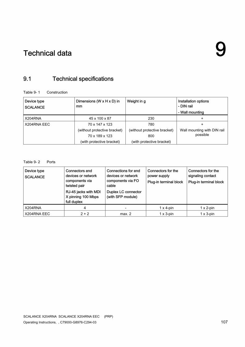
SCALANCE X204RNA SCALANCE X204RNA EEC (PRP) Operating Instructions, , C79000-G8976-C294-03 107
Technical data 99.1 Technical specifications
Table 9- 1 Construction
Device type SCALANCE
Dimensions (W x H x D) in mm
Weight in g Installation options - DIN rail - Wall mounting
X204RNA 45 x 100 x 87 230 + X204RNA EEC 70 x 147 x 123
(without protective bracket) 70 x 189 x 123
(with protective bracket)
780 (without protective bracket)
800 (with protective bracket)
+ Wall mounting with DIN rail
possible
Table 9- 2 Ports
Device type SCALANCE
Connectors end devices or network components via twisted pair RJ-45 jacks with MDI X pinning 100 Mbps full duplex
Connections for end devices or network components via FO cable Duplex LC connector (with SFP module)
Connectors for the power supply Plug-in terminal block
Connectors for the signaling contact Plug-in terminal block
X204RNA 4 - 1 x 4-pin 1 x 2-pin X204RNA EEC 2 + 2 max. 2 1 x 3-pin 1 x 3-pin
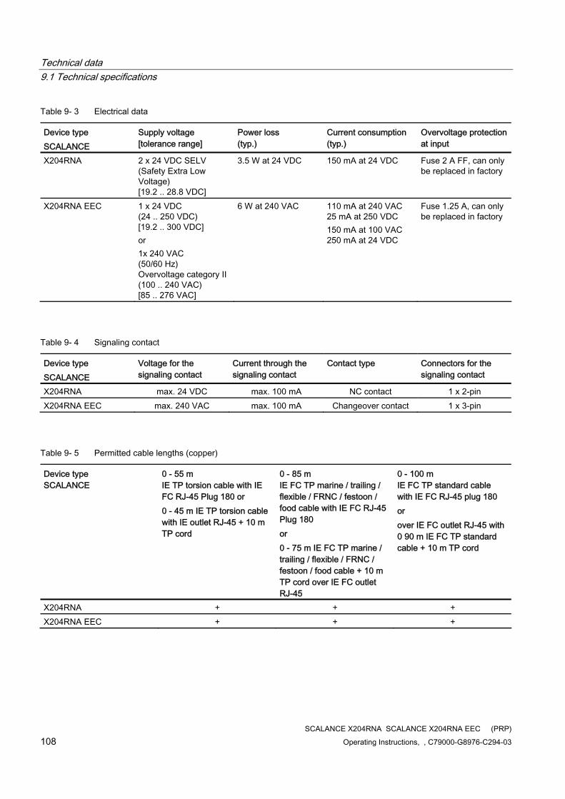
Technical data 9.1 Technical specifications
SCALANCE X204RNA SCALANCE X204RNA EEC (PRP) 108 Operating Instructions, , C79000-G8976-C294-03
Table 9- 3 Electrical data
Device type SCALANCE
Supply voltage [tolerance range]
Power loss (typ.)
Current consumption (typ.)
Overvoltage protection at input
X204RNA 2 x 24 VDC SELV (Safety Extra Low Voltage) [19.2 .. 28.8 VDC]
3.5 W at 24 VDC 150 mA at 24 VDC Fuse 2 A FF, can only be replaced in factory
X204RNA EEC 1 x 24 VDC (24 .. 250 VDC) [19.2 .. 300 VDC] or 1x 240 VAC (50/60 Hz) Overvoltage category II (100 .. 240 VAC) [85 .. 276 VAC]
6 W at 240 VAC 110 mA at 240 VAC 25 mA at 250 VDC 150 mA at 100 VAC 250 mA at 24 VDC
Fuse 1.25 A, can only be replaced in factory
Table 9- 4 Signaling contact
Device type SCALANCE
Voltage for the signaling contact
Current through the signaling contact
Contact type Connectors for the signaling contact
X204RNA max. 24 VDC max. 100 mA NC contact 1 x 2-pin X204RNA EEC max. 240 VAC max. 100 mA Changeover contact 1 x 3-pin
Table 9- 5 Permitted cable lengths (copper)
Device type SCALANCE
0 - 55 m IE TP torsion cable with IE FC RJ-45 Plug 180 or 0 - 45 m IE TP torsion cable with IE outlet RJ-45 + 10 m TP cord
0 - 85 m IE FC TP marine / trailing / flexible / FRNC / festoon / food cable with IE FC RJ-45 Plug 180 or 0 - 75 m IE FC TP marine / trailing / flexible / FRNC / festoon / food cable + 10 m TP cord over IE FC outlet RJ-45
0 - 100 m IE FC TP standard cable with IE FC RJ-45 plug 180 or over IE FC outlet RJ-45 with 0 90 m IE FC TP standard cable + 10 m TP cord
X204RNA + + + X204RNA EEC + + +
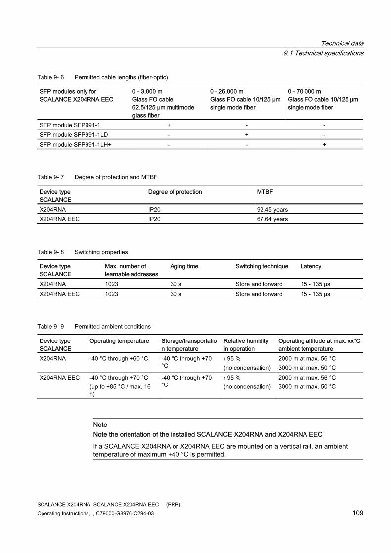
Technical data 9.1 Technical specifications
SCALANCE X204RNA SCALANCE X204RNA EEC (PRP) Operating Instructions, , C79000-G8976-C294-03 109
Table 9- 6 Permitted cable lengths (fiber-optic)
SFP modules only for SCALANCE X204RNA EEC
0 - 3,000 m Glass FO cable 62.5/125 µm multimode glass fiber
0 - 26,000 m Glass FO cable 10/125 µm single mode fiber
0 - 70,000 m Glass FO cable 10/125 µm single mode fiber
SFP module SFP991-1 + - - SFP module SFP991-1LD - + - SFP module SFP991-1LH+ - - +
Table 9- 7 Degree of protection and MTBF
Device type SCALANCE
Degree of protection MTBF
X204RNA IP20 92.45 years X204RNA EEC IP20 67.64 years
Table 9- 8 Switching properties
Device type SCALANCE
Max. number of learnable addresses
Aging time Switching technique Latency
X204RNA 1023 30 s Store and forward 15 - 135 µs X204RNA EEC 1023 30 s Store and forward 15 - 135 µs
Table 9- 9 Permitted ambient conditions
Device type SCALANCE
Operating temperature Storage/transportation temperature
Relative humidity in operation
Operating altitude at max. xx°C ambient temperature
X204RNA -40 °C through +60 °C -40 °C through +70 °C
‹ 95 % (no condensation)
2000 m at max. 56 °C 3000 m at max. 50 °C
X204RNA EEC -40 °C through +70 °C (up to +85 °C / max. 16 h)
-40 °C through +70 °C
‹ 95 % (no condensation)
2000 m at max. 56 °C 3000 m at max. 50 °C
Note Note the orientation of the installed SCALANCE X204RNA and X204RNA EEC
If a SCALANCE X204RNA or X204RNA EEC are mounted on a vertical rail, an ambient temperature of maximum +40 °C is permitted.

Technical data 9.1 Technical specifications
SCALANCE X204RNA SCALANCE X204RNA EEC (PRP) 110 Operating Instructions, , C79000-G8976-C294-03
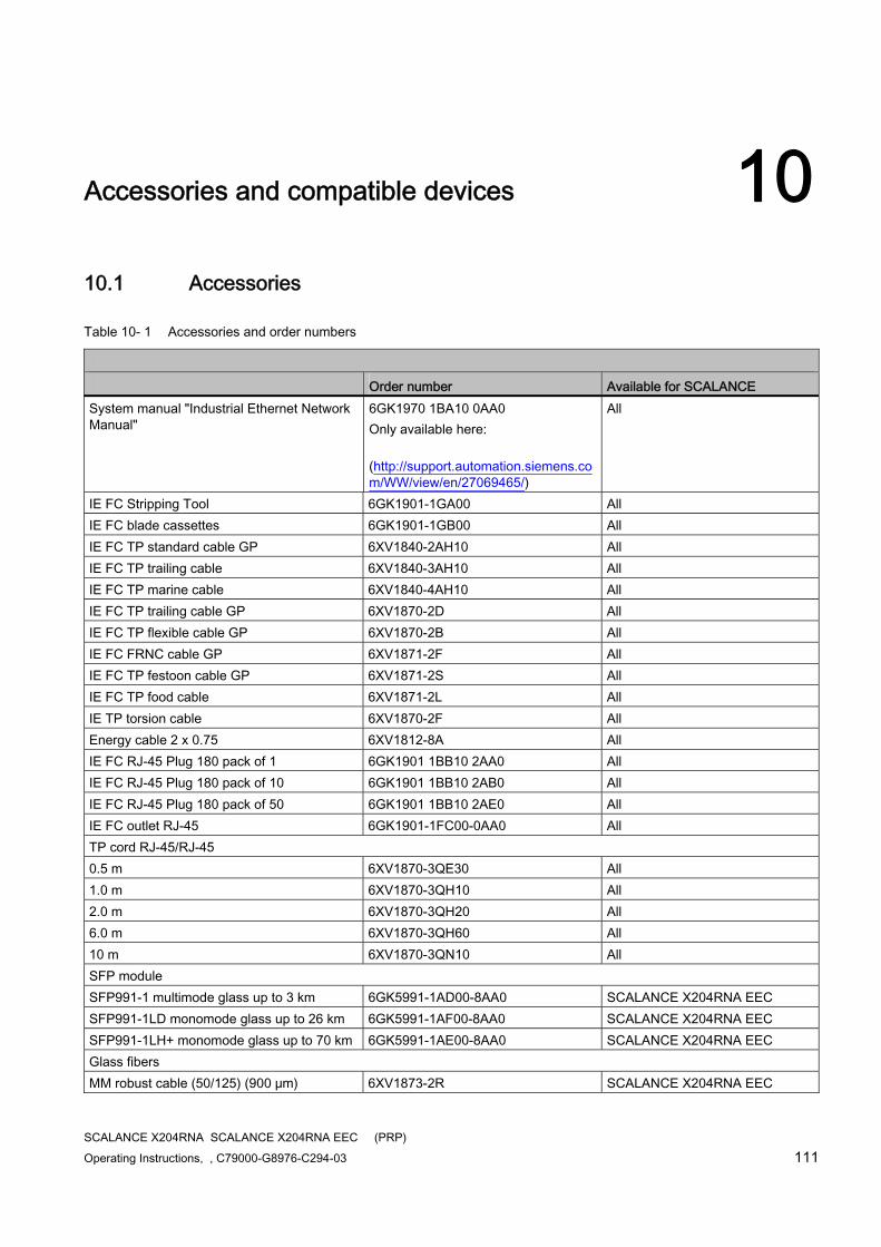
SCALANCE X204RNA SCALANCE X204RNA EEC (PRP) Operating Instructions, , C79000-G8976-C294-03 111
Accessories and compatible devices 1010.1 Accessories
Table 10- 1 Accessories and order numbers
Order number Available for SCALANCE System manual "Industrial Ethernet Network Manual"
6GK1970 1BA10 0AA0 Only available here: (http://support.automation.siemens.com/WW/view/en/27069465/)
All
IE FC Stripping Tool 6GK1901-1GA00 All IE FC blade cassettes 6GK1901-1GB00 All IE FC TP standard cable GP 6XV1840-2AH10 All IE FC TP trailing cable 6XV1840-3AH10 All IE FC TP marine cable 6XV1840-4AH10 All IE FC TP trailing cable GP 6XV1870-2D All IE FC TP flexible cable GP 6XV1870-2B All IE FC FRNC cable GP 6XV1871-2F All IE FC TP festoon cable GP 6XV1871-2S All IE FC TP food cable 6XV1871-2L All IE TP torsion cable 6XV1870-2F All Energy cable 2 x 0.75 6XV1812-8A All IE FC RJ-45 Plug 180 pack of 1 6GK1901 1BB10 2AA0 All IE FC RJ-45 Plug 180 pack of 10 6GK1901 1BB10 2AB0 All IE FC RJ-45 Plug 180 pack of 50 6GK1901 1BB10 2AE0 All IE FC outlet RJ-45 6GK1901-1FC00-0AA0 All TP cord RJ-45/RJ-45 0.5 m 6XV1870-3QE30 All 1.0 m 6XV1870-3QH10 All 2.0 m 6XV1870-3QH20 All 6.0 m 6XV1870-3QH60 All 10 m 6XV1870-3QN10 All SFP module SFP991-1 multimode glass up to 3 km 6GK5991-1AD00-8AA0 SCALANCE X204RNA EEC SFP991-1LD monomode glass up to 26 km 6GK5991-1AF00-8AA0 SCALANCE X204RNA EEC SFP991-1LH+ monomode glass up to 70 km 6GK5991-1AE00-8AA0 SCALANCE X204RNA EEC Glass fibers MM robust cable (50/125) (900 μm) 6XV1873-2R SCALANCE X204RNA EEC
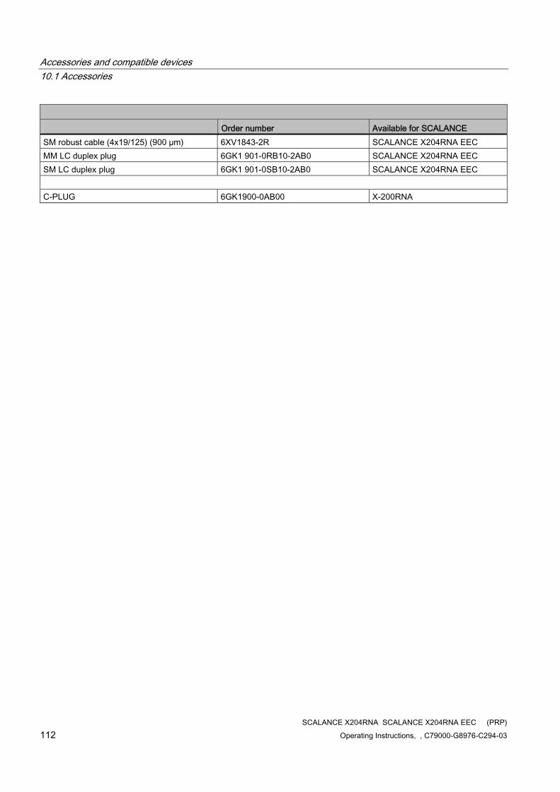
Accessories and compatible devices 10.1 Accessories
SCALANCE X204RNA SCALANCE X204RNA EEC (PRP) 112 Operating Instructions, , C79000-G8976-C294-03
Order number Available for SCALANCE SM robust cable (4x19/125) (900 µm) 6XV1843-2R SCALANCE X204RNA EEC MM LC duplex plug 6GK1 901-0RB10-2AB0 SCALANCE X204RNA EEC SM LC duplex plug 6GK1 901-0SB10-2AB0 SCALANCE X204RNA EEC C-PLUG 6GK1900-0AB00 X-200RNA
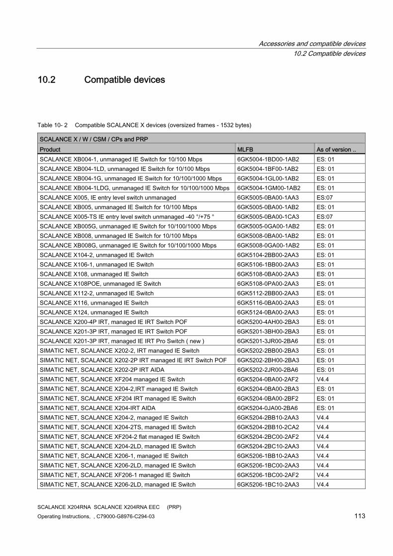
Accessories and compatible devices 10.2 Compatible devices
SCALANCE X204RNA SCALANCE X204RNA EEC (PRP) Operating Instructions, , C79000-G8976-C294-03 113
10.2 Compatible devices
Table 10- 2 Compatible SCALANCE X devices (oversized frames - 1532 bytes)
SCALANCE X / W / CSM / CPs and PRP Product MLFB As of version .. SCALANCE XB004-1, unmanaged IE Switch for 10/100 Mbps 6GK5004-1BD00-1AB2 ES: 01 SCALANCE XB004-1LD, unmanaged IE Switch for 10/100 Mbps 6GK5004-1BF00-1AB2 ES: 01 SCALANCE XB004-1G, unmanaged IE Switch for 10/100/1000 Mbps 6GK5004-1GL00-1AB2 ES: 01 SCALANCE XB004-1LDG, unmanaged IE Switch for 10/100/1000 Mbps 6GK5004-1GM00-1AB2 ES: 01 SCALANCE X005, IE entry level switch unmanaged 6GK5005-0BA00-1AA3 ES:07 SCALANCE XB005, unmanaged IE Switch for 10/100 Mbps 6GK5005-0BA00-1AB2 ES: 01 SCALANCE X005-TS IE entry level switch unmanaged -40 °/+75 ° 6GK5005-0BA00-1CA3 ES:07 SCALANCE XB005G, unmanaged IE Switch for 10/100/1000 Mbps 6GK5005-0GA00-1AB2 ES: 01 SCALANCE XB008, unmanaged IE Switch for 10/100 Mbps 6GK5008-0BA00-1AB2 ES: 01 SCALANCE XB008G, unmanaged IE Switch for 10/100/1000 Mbps 6GK5008-0GA00-1AB2 ES: 01 SCALANCE X104-2, unmanaged IE Switch 6GK5104-2BB00-2AA3 ES: 01 SCALANCE X106-1, unmanaged IE Switch 6GK5106-1BB00-2AA3 ES: 01 SCALANCE X108, unmanaged IE Switch 6GK5108-0BA00-2AA3 ES: 01 SCALANCE X108POE, unmanaged IE Switch 6GK5108-0PA00-2AA3 ES: 01 SCALANCE X112-2, unmanaged IE Switch 6GK5112-2BB00-2AA3 ES: 01 SCALANCE X116, unmanaged IE Switch 6GK5116-0BA00-2AA3 ES: 01 SCALANCE X124, unmanaged IE Switch 6GK5124-0BA00-2AA3 ES: 01 SCALANCE X200-4P IRT, managed IE IRT Switch POF 6GK5200-4AH00-2BA3 ES: 01 SCALANCE X201-3P IRT, managed IE IRT Switch POF 6GK5201-3BH00-2BA3 ES: 01 SCALANCE X201-3P IRT, managed IE IRT Pro Switch ( new ) 6GK5201-3JR00-2BA6 ES: 01 SIMATIC NET, SCALANCE X202-2, IRT managed IE Switch 6GK5202-2BB00-2BA3 ES: 01 SIMATIC NET, SCALANCE X202-2P IRT managed IE IRT Switch POF 6GK5202-2BH00-2BA3 ES: 01 SIMATIC NET, SCALANCE X202-2P IRT AIDA 6GK5202-2JR00-2BA6 ES: 01 SIMATIC NET, SCALANCE XF204 managed IE Switch 6GK5204-0BA00-2AF2 V4.4 SIMATIC NET, SCALANCE X204-2,IRT managed IE Switch 6GK5204-0BA00-2BA3 ES: 01 SIMATIC NET, SCALANCE XF204 IRT managed IE Switch 6GK5204-0BA00-2BF2 ES: 01 SIMATIC NET, SCALANCE X204-IRT AIDA 6GK5204-0JA00-2BA6 ES: 01 SIMATIC NET, SCALANCE X204-2, managed IE Switch 6GK5204-2BB10-2AA3 V4.4 SIMATIC NET, SCALANCE X204-2TS, managed IE Switch 6GK5204-2BB10-2CA2 V4.4 SIMATIC NET, SCALANCE XF204-2 flat managed IE Switch 6GK5204-2BC00-2AF2 V4.4 SIMATIC NET, SCALANCE X204-2LD, managed IE Switch 6GK5204-2BC10-2AA3 V4.4 SIMATIC NET, SCALANCE X206-1, managed IE Switch 6GK5206-1BB10-2AA3 V4.4 SIMATIC NET, SCALANCE X206-2LD, managed IE Switch 6GK5206-1BC00-2AA3 V4.4 SIMATIC NET, SCALANCE XF206-1 managed IE Switch 6GK5206-1BC00-2AF2 V4.4 SIMATIC NET, SCALANCE X206-2LD, managed IE Switch 6GK5206-1BC10-2AA3 V4.4
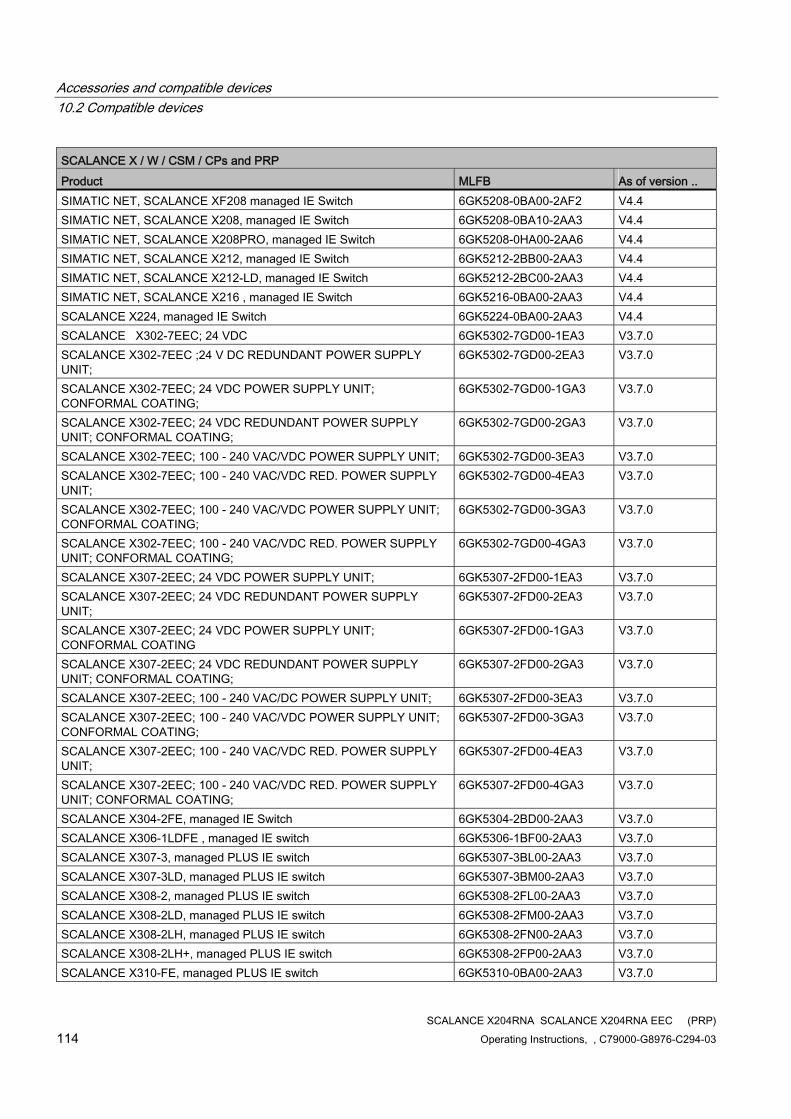
Accessories and compatible devices 10.2 Compatible devices
SCALANCE X204RNA SCALANCE X204RNA EEC (PRP) 114 Operating Instructions, , C79000-G8976-C294-03
SCALANCE X / W / CSM / CPs and PRP Product MLFB As of version .. SIMATIC NET, SCALANCE XF208 managed IE Switch 6GK5208-0BA00-2AF2 V4.4 SIMATIC NET, SCALANCE X208, managed IE Switch 6GK5208-0BA10-2AA3 V4.4 SIMATIC NET, SCALANCE X208PRO, managed IE Switch 6GK5208-0HA00-2AA6 V4.4 SIMATIC NET, SCALANCE X212, managed IE Switch 6GK5212-2BB00-2AA3 V4.4 SIMATIC NET, SCALANCE X212-LD, managed IE Switch 6GK5212-2BC00-2AA3 V4.4 SIMATIC NET, SCALANCE X216 , managed IE Switch 6GK5216-0BA00-2AA3 V4.4 SCALANCE X224, managed IE Switch 6GK5224-0BA00-2AA3 V4.4 SCALANCE X302-7EEC; 24 VDC 6GK5302-7GD00-1EA3 V3.7.0 SCALANCE X302-7EEC ;24 V DC REDUNDANT POWER SUPPLY UNIT;
6GK5302-7GD00-2EA3 V3.7.0
SCALANCE X302-7EEC; 24 VDC POWER SUPPLY UNIT; CONFORMAL COATING;
6GK5302-7GD00-1GA3 V3.7.0
SCALANCE X302-7EEC; 24 VDC REDUNDANT POWER SUPPLY UNIT; CONFORMAL COATING;
6GK5302-7GD00-2GA3 V3.7.0
SCALANCE X302-7EEC; 100 - 240 VAC/VDC POWER SUPPLY UNIT; 6GK5302-7GD00-3EA3 V3.7.0 SCALANCE X302-7EEC; 100 - 240 VAC/VDC RED. POWER SUPPLY UNIT;
6GK5302-7GD00-4EA3 V3.7.0
SCALANCE X302-7EEC; 100 - 240 VAC/VDC POWER SUPPLY UNIT; CONFORMAL COATING;
6GK5302-7GD00-3GA3 V3.7.0
SCALANCE X302-7EEC; 100 - 240 VAC/VDC RED. POWER SUPPLY UNIT; CONFORMAL COATING;
6GK5302-7GD00-4GA3 V3.7.0
SCALANCE X307-2EEC; 24 VDC POWER SUPPLY UNIT; 6GK5307-2FD00-1EA3 V3.7.0 SCALANCE X307-2EEC; 24 VDC REDUNDANT POWER SUPPLY UNIT;
6GK5307-2FD00-2EA3 V3.7.0
SCALANCE X307-2EEC; 24 VDC POWER SUPPLY UNIT; CONFORMAL COATING
6GK5307-2FD00-1GA3 V3.7.0
SCALANCE X307-2EEC; 24 VDC REDUNDANT POWER SUPPLY UNIT; CONFORMAL COATING;
6GK5307-2FD00-2GA3 V3.7.0
SCALANCE X307-2EEC; 100 - 240 VAC/DC POWER SUPPLY UNIT; 6GK5307-2FD00-3EA3 V3.7.0 SCALANCE X307-2EEC; 100 - 240 VAC/VDC POWER SUPPLY UNIT; CONFORMAL COATING;
6GK5307-2FD00-3GA3 V3.7.0
SCALANCE X307-2EEC; 100 - 240 VAC/VDC RED. POWER SUPPLY UNIT;
6GK5307-2FD00-4EA3 V3.7.0
SCALANCE X307-2EEC; 100 - 240 VAC/VDC RED. POWER SUPPLY UNIT; CONFORMAL COATING;
6GK5307-2FD00-4GA3 V3.7.0
SCALANCE X304-2FE, managed IE Switch 6GK5304-2BD00-2AA3 V3.7.0 SCALANCE X306-1LDFE , managed IE switch 6GK5306-1BF00-2AA3 V3.7.0 SCALANCE X307-3, managed PLUS IE switch 6GK5307-3BL00-2AA3 V3.7.0 SCALANCE X307-3LD, managed PLUS IE switch 6GK5307-3BM00-2AA3 V3.7.0 SCALANCE X308-2, managed PLUS IE switch 6GK5308-2FL00-2AA3 V3.7.0 SCALANCE X308-2LD, managed PLUS IE switch 6GK5308-2FM00-2AA3 V3.7.0 SCALANCE X308-2LH, managed PLUS IE switch 6GK5308-2FN00-2AA3 V3.7.0 SCALANCE X308-2LH+, managed PLUS IE switch 6GK5308-2FP00-2AA3 V3.7.0 SCALANCE X310-FE, managed PLUS IE switch 6GK5310-0BA00-2AA3 V3.7.0
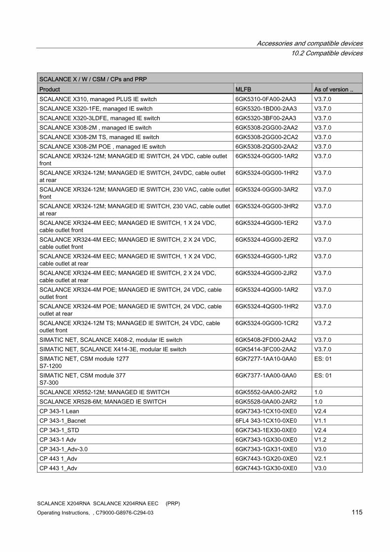
Accessories and compatible devices 10.2 Compatible devices
SCALANCE X204RNA SCALANCE X204RNA EEC (PRP) Operating Instructions, , C79000-G8976-C294-03 115
SCALANCE X / W / CSM / CPs and PRP Product MLFB As of version .. SCALANCE X310, managed PLUS IE switch 6GK5310-0FA00-2AA3 V3.7.0 SCALANCE X320-1FE, managed IE switch 6GK5320-1BD00-2AA3 V3.7.0 SCALANCE X320-3LDFE, managed IE switch 6GK5320-3BF00-2AA3 V3.7.0 SCALANCE X308-2M , managed IE switch 6GK5308-2GG00-2AA2 V3.7.0 SCALANCE X308-2M TS, managed IE switch 6GK5308-2GG00-2CA2 V3.7.0 SCALANCE X308-2M POE , managed IE switch 6GK5308-2QG00-2AA2 V3.7.0 SCALANCE XR324-12M; MANAGED IE SWITCH, 24 VDC, cable outlet front
6GK5324-0GG00-1AR2 V3.7.0
SCALANCE XR324-12M; MANAGED IE SWITCH, 24VDC, cable outlet at rear
6GK5324-0GG00-1HR2 V3.7.0
SCALANCE XR324-12M; MANAGED IE SWITCH, 230 VAC, cable outlet front
6GK5324-0GG00-3AR2 V3.7.0
SCALANCE XR324-12M; MANAGED IE SWITCH, 230 VAC, cable outlet at rear
6GK5324-0GG00-3HR2 V3.7.0
SCALANCE XR324-4M EEC; MANAGED IE SWITCH, 1 X 24 VDC, cable outlet front
6GK5324-4GG00-1ER2 V3.7.0
SCALANCE XR324-4M EEC; MANAGED IE SWITCH, 2 X 24 VDC, cable outlet front
6GK5324-4GG00-2ER2 V3.7.0
SCALANCE XR324-4M EEC; MANAGED IE SWITCH, 1 X 24 VDC, cable outlet at rear
6GK5324-4GG00-1JR2 V3.7.0
SCALANCE XR324-4M EEC; MANAGED IE SWITCH, 2 X 24 VDC, cable outlet at rear
6GK5324-4GG00-2JR2 V3.7.0
SCALANCE XR324-4M POE; MANAGED IE SWITCH, 24 VDC, cable outlet front
6GK5324-4QG00-1AR2 V3.7.0
SCALANCE XR324-4M POE; MANAGED IE SWITCH, 24 VDC, cable outlet at rear
6GK5324-4QG00-1HR2 V3.7.0
SCALANCE XR324-12M TS; MANAGED IE SWITCH, 24 VDC, cable outlet front
6GK5324-0GG00-1CR2 V3.7.2
SIMATIC NET, SCALANCE X408-2, modular IE switch 6GK5408-2FD00-2AA2 V3.7.0 SIMATIC NET, SCALANCE X414-3E, modular IE switch 6GK5414-3FC00-2AA2 V3.7.0 SIMATIC NET, CSM module 1277 S7-1200
6GK7277-1AA10-0AA0 ES: 01
SIMATIC NET, CSM module 377 S7-300
6GK7377-1AA00-0AA0 ES: 01
SCALANCE XR552-12M; MANAGED IE SWITCH 6GK5552-0AA00-2AR2 1.0 SCALANCE XR528-6M; MANAGED IE SWITCH 6GK5528-0AA00-2AR2 1.0 CP 343-1 Lean 6GK7343-1CX10-0XE0 V2.4 CP 343-1_Bacnet 6FL4 343-1CX10-0XE0 V1.1 CP 343-1_STD 6GK7343-1EX30-0XE0 V2.4 CP 343-1 Adv 6GK7343-1GX30-0XE0 V1.2 CP 343-1_Adv-3.0 6GK7343-1GX31-0XE0 V3.0 CP 443 1_Adv 6GK7443-1GX20-0XE0 V2.1 CP 443 1_Adv 6GK7443-1GX30-0XE0 V3.0
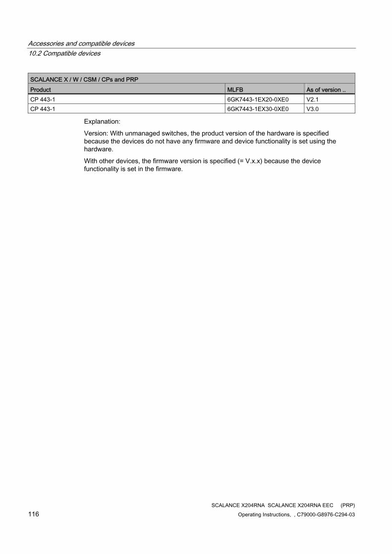
Accessories and compatible devices 10.2 Compatible devices
SCALANCE X204RNA SCALANCE X204RNA EEC (PRP) 116 Operating Instructions, , C79000-G8976-C294-03
SCALANCE X / W / CSM / CPs and PRP Product MLFB As of version .. CP 443-1 6GK7443-1EX20-0XE0 V2.1 CP 443-1 6GK7443-1EX30-0XE0 V3.0
Explanation:
Version: With unmanaged switches, the product version of the hardware is specified because the devices do not have any firmware and device functionality is set using the hardware.
With other devices, the firmware version is specified (= V.x.x) because the device functionality is set in the firmware.
SCALANCE X204RNA SCALANCE X204RNA EEC (PRP) Operating Instructions, , C79000-G8976-C294-03 117
References 1111.1 References
Sources of information and other documentation System manual "SIMATIC NET Industrial Ethernet Network Manual"
The system manuals are only available from the CS home page.
(http://support.automation.siemens.com/WW/view/en/27069465/)

References 11.1 References
SCALANCE X204RNA SCALANCE X204RNA EEC (PRP) 118 Operating Instructions, , C79000-G8976-C294-03
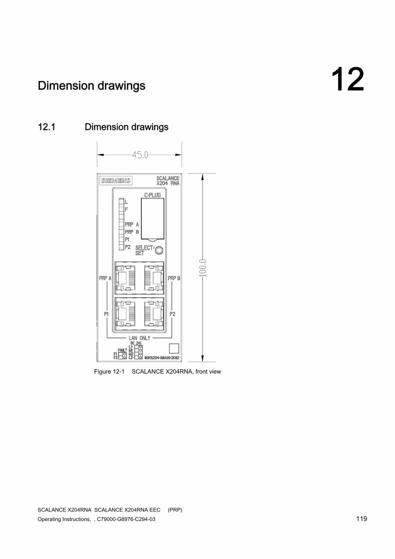
SCALANCE X204RNA SCALANCE X204RNA EEC (PRP) Operating Instructions, , C79000-G8976-C294-03 119
Dimension drawings 1212.1 Dimension drawings
Figure 12-1 SCALANCE X204RNA, front view
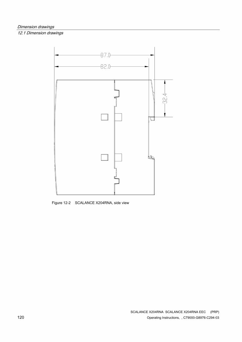
Dimension drawings 12.1 Dimension drawings
SCALANCE X204RNA SCALANCE X204RNA EEC (PRP) 120 Operating Instructions, , C79000-G8976-C294-03
Figure 12-2 SCALANCE X204RNA, side view
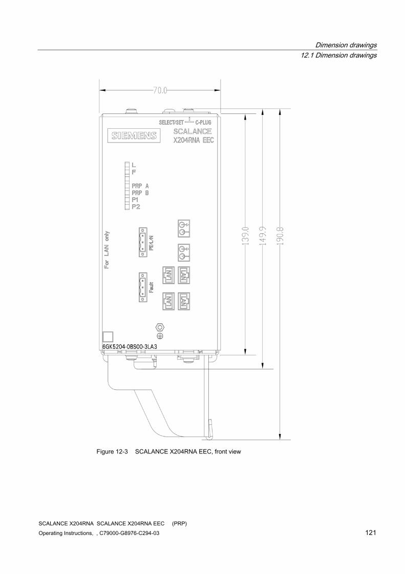
Dimension drawings 12.1 Dimension drawings
SCALANCE X204RNA SCALANCE X204RNA EEC (PRP) Operating Instructions, , C79000-G8976-C294-03 121
Figure 12-3 SCALANCE X204RNA EEC, front view
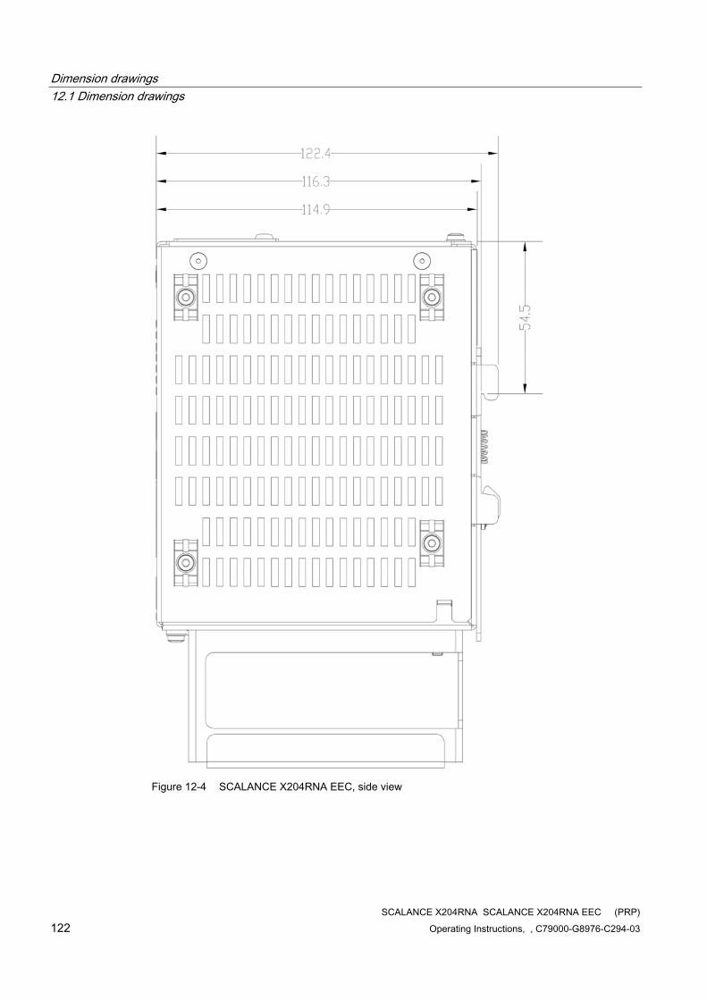
Dimension drawings 12.1 Dimension drawings
SCALANCE X204RNA SCALANCE X204RNA EEC (PRP) 122 Operating Instructions, , C79000-G8976-C294-03
Figure 12-4 SCALANCE X204RNA EEC, side view
SCALANCE X204RNA SCALANCE X204RNA EEC (PRP) Operating Instructions, , C79000-G8976-C294-03 123
Glossary
Aging time The aging time is the time after which a learned address is discarded if a SCALANCE X-200RNA has not received frames with this sender address during this time.
Autocrossover Technique with which a TP port is automatically switched over between MDI and MDI-X assignment to make a connection independent of the port assignment of the device being attached. This means that crossover cables are not required. The autocrossover function can only be used when the port is set to autonegotiation mode.
Autonegotiation Procedure standardized by IEEE 802.3 in which the transmission parameters (for example 10/100 Mbps, full/half duplex) are negotiated automatically between the devices.
BOOTP A protocol for automatic assignment of IP addresses. The IP addresses are provided by a BOOTP server
CLI Command Line Interface. Terminal-based configuration option for SCALANCE. The CLI can be used via an Ethernet connection.
C-PLUG The C-PLUG (configuration plug) is an exchangeable medium for storage of the configuration and project engineering data. If the device is replaced, the configuration can be adopted by swapping the C-PLUG.
CRC Cyclic Redundancy Check. A checksum used in transmission protocols to detect errors in frames.
DCP DCP (Discovery and basic Configuration Protocol) is used to detect nodes without an IP address and to assign a basic configuration to them, for example IP address.
Glossary
SCALANCE X204RNA SCALANCE X204RNA EEC (PRP) 124 Operating Instructions, , C79000-G8976-C294-03
Default gateway A network node that forwards all frames not addressed to stations in the same LAN (subnet).
DHCP DHCP (Dynamic Host Configuration Protocol), like BOOTP, a method for automatic assignment of IP addresses. However, with DHCP, addresses can also be assigned while the device is running.
Event for Alarms & Events: An event is any occurrence that might be of interest to the client. Although events can also be generated due to a condition being met, they do not need to be related to conditions. Events that are not related to conditions include, for example, error messages from the communications system.
Fault mask Specifies the desired status (good status). Deviations from this occurring during operation are handled as faults.
High Speed Redundancy Method used on SIMATIC NET switches to increase the network availability in a ring topology.
See also ►Media redundancy.
HTTP Hypertext Transfer Protocol.
Protocol for transfer from Web sites
Media redundancy Method for increasing availability in Industrial Ethernet networks in which devices can be reached over different paths. This might be achieved by meshing networks, arranging parallel transmission paths or by closing a linear bus topology to form a ring.
Media redundancy within a ring topology is available with SIMATIC NET products with the ►High Speed Redundancy and ►MRP methods.
Media Redundancy Protocol A method specified in the IEC 61158 Type 10 standard for increasing network availability in a ring topology.
See also ►Media redundancy.
Glossary
SCALANCE X204RNA SCALANCE X204RNA EEC (PRP) Operating Instructions, , C79000-G8976-C294-03 125
MIB Managed Information Base. A tree structure containing all the data relevant for network management in SNMP.
Mirroring A port (mirror port) with its specific data traffic can be mirrored to another port (monitor port) for test purposes. Protocol analysis devices can be connected to the monitor port, in other words, the monitor port is not available for data exchange. Mirroring has no effect on the mirror port.
MRP → Media Redundancy Protocol
Multicast A frame with a multicast address is received by all nodes prepared to receive this address.
Multimode In multimode transmission, the pulse is transferred using many modes (waves) that travel along curved paths or are reflected within the core. Attenuation is mainly caused by physical absorption and dispersion as well as by mechanical bending. The amount of attenuation depends, among other things, on the wavelength of the input light. Multimode fiber-optic cables have an outer diameter of 125 µm and 50 or 62.5 µm core diameter. Due to the larger core diameter the pulse edges degrade more than in single mode transmission resulting in shorter transmission distances.
PRP PRP is a redundancy protocol for Ethernet networks. It is defined in the standard IEC 62439 (Industrial Communication Networks - High Availability Automation Networks) in Part 3 (Parallel Redundancy Protocol (PRP) and High-availability Seamless Redundancy (HSR)). With PRP, frames are exchanged at the same time via a two separate Ethernet networks. If a transmission path is interrupted, the frame arrives at its destination via the second path. This is bumpless without reconfiguration times to find new paths.
RMON Remote Monitoring. RMON-compliant devices allow diagnostic data to be collected on the device and read out by a network management station. This means that network problems are detected early and can be eliminated. The particular advantage of RMON is that it is independent of location. The acquired data can be analyzed at any point in the network with suitable reporting software.
Glossary
SCALANCE X204RNA SCALANCE X204RNA EEC (PRP) 126 Operating Instructions, , C79000-G8976-C294-03
RNA Redundant network access, connection point for connecting end devices/network segments not capable of PRP to parallel networks.
RSTP Rapid Spanning Tree protocol. Variant of the Spanning Tree protocol optimized for speed.
This protocol prevents loops forming in multiple, redundant network connections. If there is an interruption on a connection, the network is automatically reconfigured so that there is exactly one connection between all nodes.
Secure Shell → SSH
Secure Socket Layer → SSL
Segment In the Ethernet bus system, transceivers connected together over the bus cable along with the nodes connected over patch cables form a segment. Several such segments can be connected via repeaters. When using twisted pair and fiber-optic cables, each subsection forms a segment.
SFF Small Form-Factor
The SFF slot is used to insert SFP modules. See also SFP.
SFP Small Form-Factor Pluggable.
SFP is a specification for modular optical or electrical transceivers for network connections. SFP modules fit in an SFF slot and can be replaced simply and quickly (hot swapping).
Signaling contact Floating relay contact via which the detected error states can be signaled.
Glossary
SCALANCE X204RNA SCALANCE X204RNA EEC (PRP) Operating Instructions, , C79000-G8976-C294-03 127
Single mode In single mode transmission, (and monomode transmission) the pulse is transmitted by a straight mode (wave). Attenuation is mainly caused by physical absorption and dispersion as well as by mechanical bending. The amount of attenuation depends, among other things, on the wavelength of the input light. The single mode fiber typically has a core diameter of 5 to 9 µm. The outer diameter is, however, once again 125 µm (compare multimode). The smaller core diameter degrades the pulse edges less than multimode transmission and allows greater transmission distances.
SNMP Simple Network Management Protocol. Standardized protocol for transporting network management information.
SNTP Simple Network Time Protocol
Protocol for time synchronization over networks.
SSH Secure Shell. This allows an interactive connection to be established to another device in the LAN or on the Internet. Otherwise, the functionality corresponds to that of Telnet.
SSL Secure Socket Layer. This protocol allows encrypted exchange of data with a server. There is also secure authentication of the server. For communication with a server over SSL, the server must have a certificate and a corresponding private key.
Store and forward An entire frame is received, its validity checked (checksum, length etc.) and then buffered. Invalid frames are discarded, in other words, a frame is forwarded only when it is error-free.
TELNET With this protocol, an interactive connection can be established to another device in the LAN or on the Internet. The user then has the same options as when directly connected to this device with a terminal.
TP Twisted Pair
Glossary
SCALANCE X204RNA SCALANCE X204RNA EEC (PRP) 128 Operating Instructions, , C79000-G8976-C294-03
TP port Port with a TP connector (RJ-45 jack)
WBM Web Based Management. With WBM, configuration and diagnostics are handled with an Internet browser. Entries made by the user are sent to the device using the HTTP protocol and the device transfers its replies by HTTP to the user.

Glossary
SCALANCE X204RNA SCALANCE X204RNA EEC (PRP) Operating Instructions, , C79000-G8976-C294-03 129

SCALANCE X204RNA SCALANCE X204RNA EEC (PRP) Operating Instructions, , C79000-G8976-C294-03 131
Index
A Aging time, 99 ATEX, 10, 114 Autonegotiation, 21, 26, 100
B BOOTP, 77
C Certifications and approvals, 8 Connector pinout
SCALANCE X204RNA, 15, 20 SCALANCE X204RNA EEC, 25
C-Tick approval, 115 C-Tick mark, 8
D DCP, 78 DCP Read Only, 78 Declaration of conformity, 113 Default gateway, 78 DHCP, 78 Displays
Fault display, 32 Port status indication, 33 Power display, 32
E E-mail, 77 E-mail address, 91 EMC directive, 113 Error
Bad Frames, 108 CRC, 108 Dropped L2, 108 Oversize, 108 Undersize, 108
F Factory Defaults, 59 Fault mask, 72 FM approval, 115
G Group Name, 84, 86
H Hazardous (Ex) area, 10 HTTPS Only, 77
I IP address, 76, 79
K Kc approval, 116
L LED simulation, 53
M MDI / MDIX autocrossover function, 21, 26
N Network topology, 13
Parallel Redundancy Protocol, 14
P Port
Port configuration, 99 Possible attachments
SCALANCE X204RNA, 19 SCALANCE X204RNA EEC, 23
Index
SCALANCE X204RNA SCALANCE X204RNA EEC (PRP) 132 Operating Instructions, , C79000-G8976-C294-03
R Redundancy error, 32 Refresh, 55 Repeat, 79 Restart, 59
S Safety notices, 9 Security level, 84 Set Value, 55 SMTP server IP address, 92 SMTP Server Port, 92 SNMP, 80
SNMP trap, 82 SNTP, 78 SSH, 77 Statistics, 103 Subnet mask, 76 Switch
Switch Forwarding Database, 101 Syslog, 78, 92, 95
T TELNET, 77 Time of day
SNTP (Simple Network Time Protocol), 96 Time zone, 97 Time-of-day synchronization, 96 UTC time, 97
Time zone, 97 Timeout, 87
U UL approval, 8
to UL 508, 116 to UL 60950, 116
User Name, 86 UTC time, 97
W Web Based Management, 50