Embed Size (px)
Citation preview
CAT.E 411 -UK
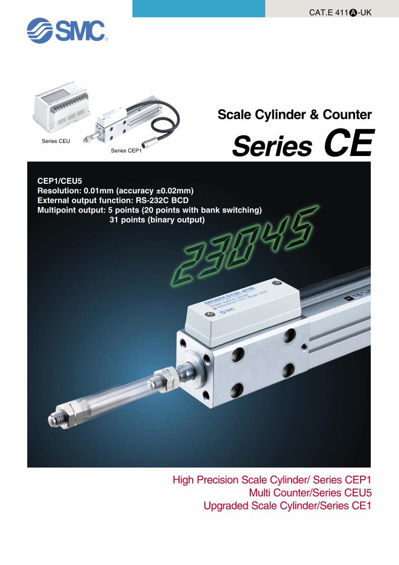
CEP1/CEU5Resolution: 0.01mm (accuracy ±0.02mm)External output function: RS-232C BCDMultipoint output: 5 points (20 points with bank switching) 31 points (binary output)
Scale Cylinder & Counter
Series CE
High Precision Scale Cylinder/ Series CEP1Multi Counter/Series CEU5
Upgraded Scale Cylinder/Series CE1
Series CEU
Series CEP1
12
20
32
40
50
63
25
50
75
100
125
150
175
200
300
500
250
400
25
50
75
100
NPN PNP NPN PNP 5
10
15
20
MULTI COUNTER:CEU5 A COM COM COMB DC12V GND F.G. R.S. HOLD BANK1 BANK2
COM S.STOPOUT1OUT2OUT3OUT4OUT5AC100~240V
COUNT PRESET FUNC.
SD SGRD RS-232C
UP
LEFT RIGHT
DOWN
SEL. SETMODE
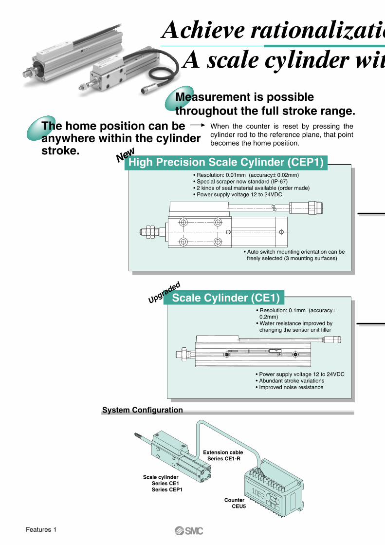
Achieve rationalization of production linesA scale cylinder with position feedback
Measurement is possible throughout the full stroke range.
The home position can be anywhere within the cylinder stroke.
When the counter is reset by pressing the cylinder rod to the reference plane, that point becomes the home position.
New
• Resolution: 0.01mm (accuracy± 0.02mm)• Special scraper now standard (IP-67)• 2 kinds of seal material available (order made)• Power supply voltage 12 to 24VDC
• Power supply voltage 12 to 24VDC• Abundant stroke variations• Improved noise resistance
Upgraded
High Precision Scale Cylinder (CEP1)
Scale Cylinder (CE1)
• Auto switch mounting orientation can be freely selected (3 mounting surfaces)
• Resolution: 0.1mm (accuracy± 0.2mm)
• Water resistance improved by changing the sensor unit filler
System Configuration
Scale cylinder Series CE1 Series CEP1
Counter CEU5
Extension cable Series CE1-R
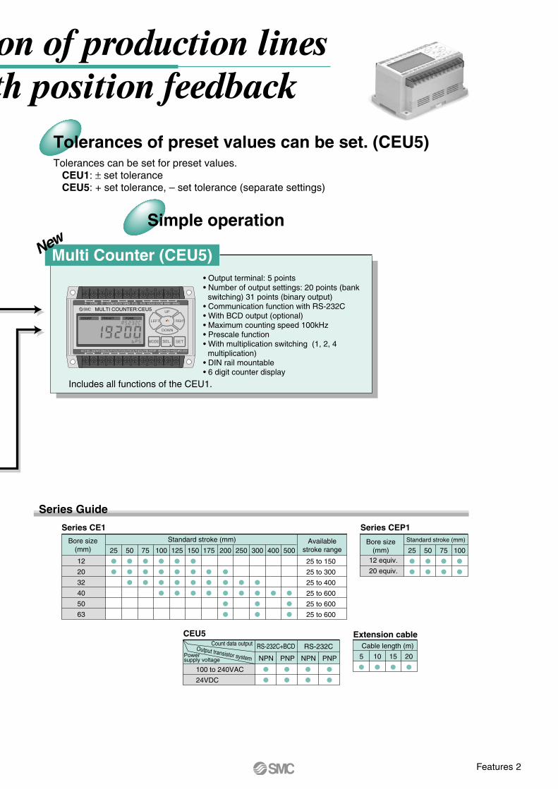
Tolerances of preset values can be set. (CEU5)Tolerances can be set for preset values. CEU1: ± set tolerance CEU5: + set tolerance, – set tolerance (separate settings)
Multi Counter (CEU5)
Series Guide
Series CE1
Bore size(mm)
Availablestroke range
Standard stroke (mm)
Series CEP1
Bore size(mm)
12 equiv.
20 equiv.
Standard stroke (mm)
CEU5Count data output
Output transistor systemPowersupply voltage
100 to 240VAC
24VDC
RS-232CRS-232C+BCD
Extension cableCable length (m)
25 to 150
25 to 300
25 to 400
25 to 600
25 to 600
25 to 600
Includes all functions of the CEU1.
• Output terminal: 5 points• Number of output settings: 20 points (bank
switching) 31 points (binary output)• Communication function with RS-232C• With BCD output (optional)• Maximum counting speed 100kHz• Prescale function• With multiplication switching (1, 2, 4
multiplication)• DIN rail mountable• 6 digit counter display
Simple operation
New
Features 1
Features 2
12
20
32
40
50
63
25
50
75
100
125
150
175
200
300
500
250
400
25
50
75
100
NPN PNP NPN PNP 5
10
15
20
MULTI COUNTER:CEU5 A COM COM COMB DC12V GND F.G. R.S. HOLD BANK1 BANK2
COM S.STOPOUT1OUT2OUT3OUT4OUT5AC100~240V
COUNT PRESET FUNC.
SD SGRD RS-232C
UP
LEFT RIGHT
DOWN
SEL. SETMODE
Achieve rationalization of production linesA scale cylinder with position feedback
Measurement is possible throughout the full stroke range.
The home position can be anywhere within the cylinder stroke.
When the counter is reset by pressing the cylinder rod to the reference plane, that point becomes the home position.
New
• Resolution: 0.01mm (accuracy± 0.02mm)• Special scraper now standard (IP-67)• 2 kinds of seal material available (order made)• Power supply voltage 12 to 24VDC
• Power supply voltage 12 to 24VDC• Abundant stroke variations• Improved noise resistance
Upgraded
High Precision Scale Cylinder (CEP1)
Scale Cylinder (CE1)
• Auto switch mounting orientation can be freely selected (3 mounting surfaces)
• Resolution: 0.1mm (accuracy± 0.2mm)
• Water resistance improved by changing the sensor unit filler
System Configuration
Scale cylinder Series CE1 Series CEP1
Counter CEU5
Extension cable Series CE1-R
Tolerances of preset values can be set. (CEU5)Tolerances can be set for preset values. CEU1: ± set tolerance CEU5: + set tolerance, – set tolerance (separate settings)
Multi Counter (CEU5)
Series Guide
Series CE1
Bore size(mm)
Availablestroke range
Standard stroke (mm)
Series CEP1
Bore size(mm)
12 equiv.
20 equiv.
Standard stroke (mm)
CEU5Count data output
Output transistor systemPowersupply voltage
100 to 240VAC
24VDC
RS-232CRS-232C+BCD
Extension cableCable length (m)
25 to 150
25 to 300
25 to 400
25 to 600
25 to 600
25 to 600
Includes all functions of the CEU1.
• Output terminal: 5 points• Number of output settings: 20 points (bank
switching) 31 points (binary output)• Communication function with RS-232C• With BCD output (optional)• Maximum counting speed 100kHz• Prescale function• With multiplication switching (1, 2, 4
multiplication)• DIN rail mountable• 6 digit counter display
Simple operation
New
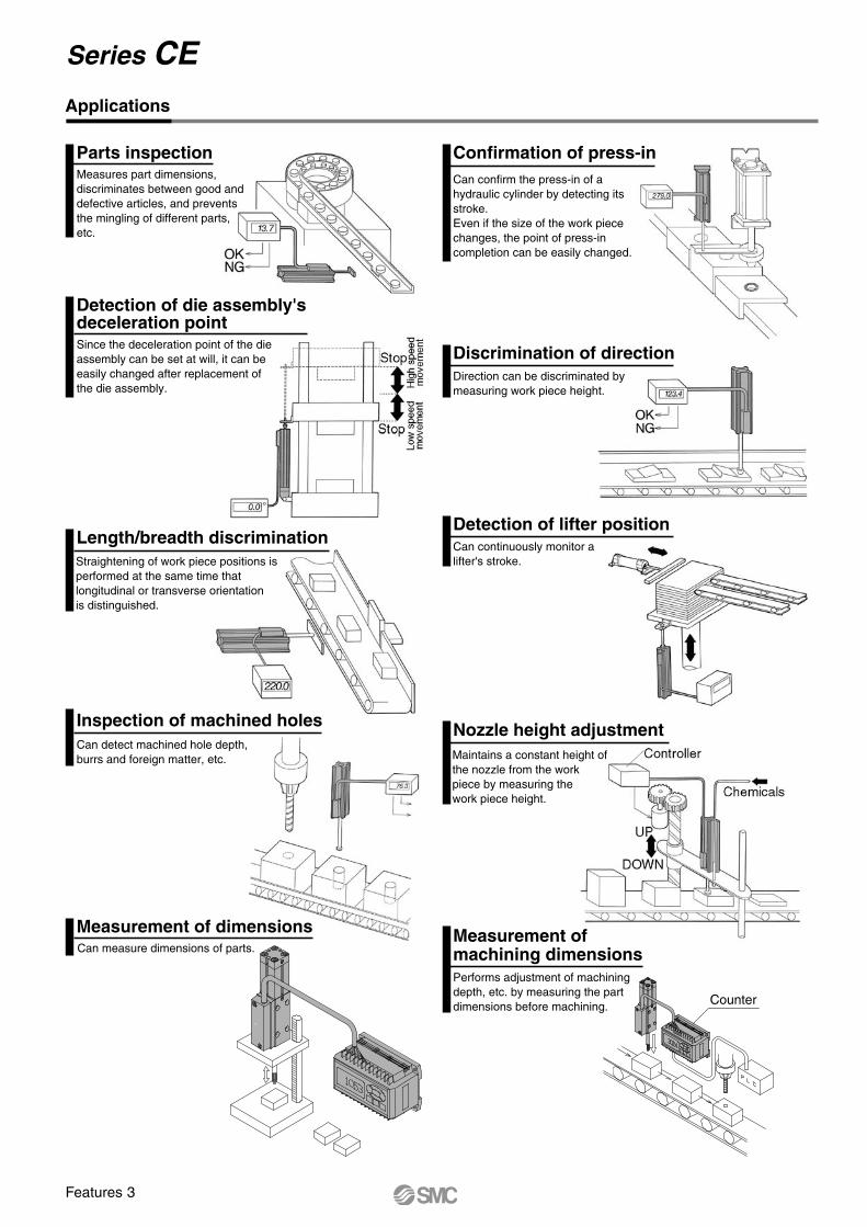
Applications
Detection of die assembly'sdeceleration pointSince the deceleration point of the dieassembly can be set at will, it can be easily changed after replacement of the die assembly.
Length/breadth discriminationStraightening of work piece positions is performed at the same time thatlongitudinal or transverse orientationis distinguished.
Inspection of machined holesCan detect machined hole depth, burrs and foreign matter, etc.
Measurement of dimensionsCan measure dimensions of parts.
Measurement ofmachining dimensions
Nozzle height adjustment
Performs adjustment of machining depth, etc. by measuring the partdimensions before machining.
Maintains a constant height of the nozzle from the workpiece by measuring thework piece height.
Detection of lifter positionCan continuously monitor a lifter's stroke.
Discrimination of directionDirection can be discriminated bymeasuring work piece height.
Confirmation of press-inCan confirm the press-in of a hydraulic cylinder by detecting itsstroke.Even if the size of the work piece changes, the point of press-incompletion can be easily changed.
Parts inspectionMeasures part dimensions, discriminates between good and defective articles, and prevents the mingling of different parts, etc.
Counter
Series CE
Features 3
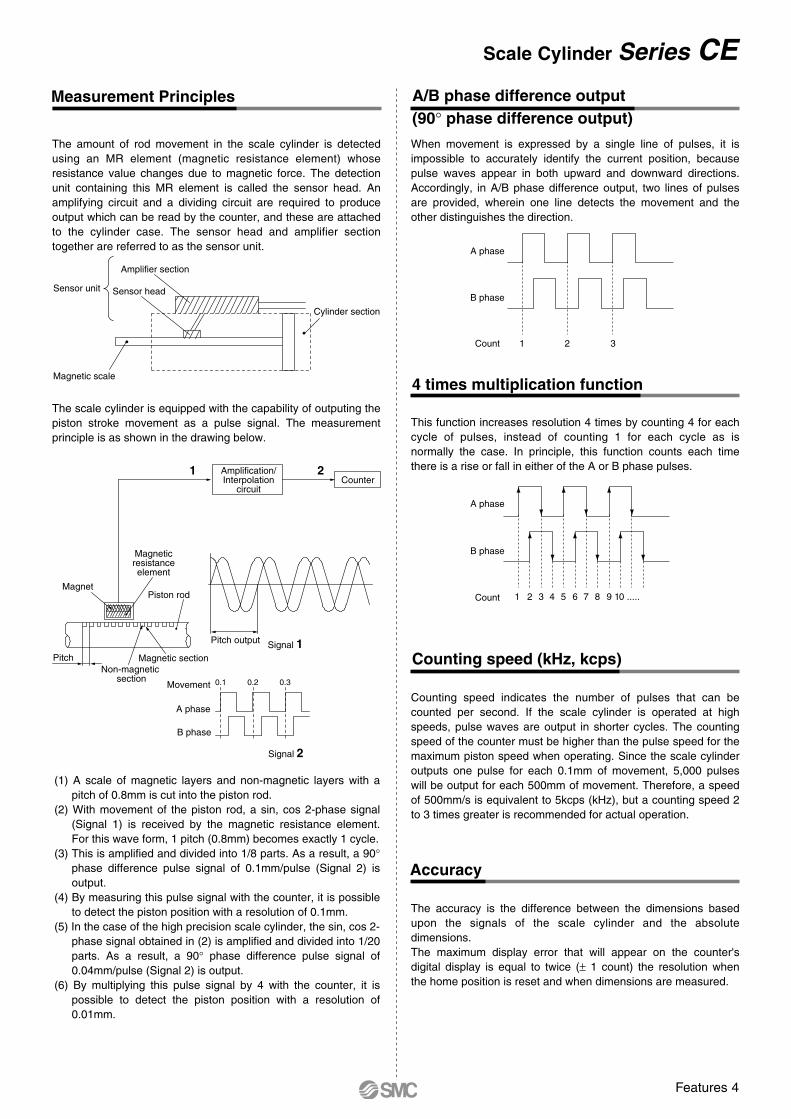
Measurement Principles A/B phase difference output (90° phase difference output)
The amount of rod movement in the scale cylinder is detected using an MR element (magnetic resistance element) whose resistance value changes due to magnetic force. The detection unit containing this MR element is called the sensor head. An amplifying circuit and a dividing circuit are required to produce output which can be read by the counter, and these are attached to the cylinder case. The sensor head and amplifier section together are referred to as the sensor unit.
(1) A scale of magnetic layers and non-magnetic layers with a pitch of 0.8mm is cut into the piston rod.
(2) With movement of the piston rod, a sin, cos 2-phase signal (Signal 1) is received by the magnetic resistance element. For this wave form, 1 pitch (0.8mm) becomes exactly 1 cycle.
(3) This is amplified and divided into 1/8 parts. As a result, a 90° phase difference pulse signal of 0.1mm/pulse (Signal 2) is output.
(4) By measuring this pulse signal with the counter, it is possible to detect the piston position with a resolution of 0.1mm.
(5) In the case of the high precision scale cylinder, the sin, cos 2-phase signal obtained in (2) is amplified and divided into 1/20 parts. As a result, a 90° phase difference pulse signal of 0.04mm/pulse (Signal 2) is output.
(6) By multiplying this pulse signal by 4 with the counter, it is possible to detect the piston position with a resolution of 0.01mm.
The scale cylinder is equipped with the capability of outputing the piston stroke movement as a pulse signal. The measurement principle is as shown in the drawing below.
When movement is expressed by a single line of pulses, it is impossible to accurately identify the current position, because pulse waves appear in both upward and downward directions. Accordingly, in A/B phase difference output, two lines of pulses are provided, wherein one line detects the movement and the other distinguishes the direction.
4 times multiplication function
A phase
B phase
Count 1 2 3
This function increases resolution 4 times by counting 4 for each cycle of pulses, instead of counting 1 for each cycle as is normally the case. In principle, this function counts each time there is a rise or fall in either of the A or B phase pulses.
A phase
B phase
Count 1 2 3 4 5 6 7 8 9 10 .....
Counting speed (kHz, kcps)
Counting speed indicates the number of pulses that can be counted per second. If the scale cylinder is operated at high speeds, pulse waves are output in shorter cycles. The counting speed of the counter must be higher than the pulse speed for the maximum piston speed when operating. Since the scale cylinder outputs one pulse for each 0.1mm of movement, 5,000 pulses will be output for each 500mm of movement. Therefore, a speed of 500mm/s is equivalent to 5kcps (kHz), but a counting speed 2 to 3 times greater is recommended for actual operation.
Accuracy
The accuracy is the difference between the dimensions based upon the signals of the scale cylinder and the absolute dimensions.The maximum display error that will appear on the counter's digital display is equal to twice (± 1 count) the resolution when the home position is reset and when dimensions are measured.
0.20.1 0.3
Sensor unit
Amplifier section
Sensor head
Magnetic scale
Cylinder section
1
Signal 1
Signal 2
2
Pitch output
Piston rodMagnet
Magneticresistanceelement
Amplification/Interpolation
circuitCounter
Magnetic section
A phase
Movement
B phase
PitchNon-magnetic
section
Scale Cylinder Series CE
Features 4
Applications
Detection of die assembly'sdeceleration pointSince the deceleration point of the dieassembly can be set at will, it can be easily changed after replacement of the die assembly.
Length/breadth discriminationStraightening of work piece positions is performed at the same time thatlongitudinal or transverse orientationis distinguished.
Inspection of machined holesCan detect machined hole depth, burrs and foreign matter, etc.
Measurement of dimensionsCan measure dimensions of parts.
Measurement ofmachining dimensions
Nozzle height adjustment
Performs adjustment of machining depth, etc. by measuring the partdimensions before machining.
Maintains a constant height of the nozzle from the workpiece by measuring thework piece height.
Detection of lifter positionCan continuously monitor a lifter's stroke.
Discrimination of directionDirection can be discriminated bymeasuring work piece height.
Confirmation of press-inCan confirm the press-in of a hydraulic cylinder by detecting itsstroke.Even if the size of the work piece changes, the point of press-incompletion can be easily changed.
Parts inspectionMeasures part dimensions, discriminates between good and defective articles, and prevents the mingling of different parts, etc.
Counter
How to Order
Applicable auto switch types
Ree
d s
wit
chS
olid
sta
te s
wit
ch
Special functionType Indicatorlight
Load voltage
ACDCWiring
(output)
No
Yes
Yes
2 wire
2 wire
3 wire
3 wire(NPN)
3 wire(PNP)
2 wire
3 wire(NPN)
3 wire(PNP)
2 wire
2 wire
A90V
A93V
A96V
M9NV
M9PV
M9BV
M9NWV
M9PWV
M9BWV
–
A90
A93
A96
M9N
M9P
M9B
M9NW
M9PW
M9BW
M9BA
–
RelayPLC
IC circuit
RelayPLC
RelayPLC
RelayPLC
RelayPLC
RelayPLC
RelayPLC
–
–
–
–
–
–
Diagnosticindication
(2 colour indicator)
Waterresistant
(2 colour indicator)
––
––
24V or less48V or less
100V or less24V
–4 to 8V
10 to 28V
10 to 28V
10 to 28V
10 to 28V
10 to 28V
10 to 28V
12V, 24V
24V or less48V or less
100V or less–
100V–
–
–
–
–
–
–
–
50mA40mA20mA
5 to 40mA5 to 20mA
20mA
50mA
5 to 30mA
50mA
5 to 30mA
5 to 30mA
IC circuit
Electrical entry direction
LateralVertical
Lead wire length (m)Applicable
load
Maximumload current
& load current range0.5(Nil)
3(L)
5(Z)
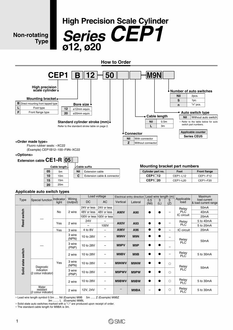
CEP1 B 5012
Direct mounting front tapped type
Foot type
Front flange type
Mounting bracketBLF
ø12mm equiv.
ø20mm equiv.
Bore size1220
Standard cylinder stroke (mm)Refer to the standard stroke table on page 2.
0.5m
3m
2pcs.
1pc.
"n" pcs.
Auto switch typeNil Without auto switch
Number of auto switchesNilSn
Cable lengthNil
L
With connector
Without connector
Nil
Z
Applicable counter
Series CEU5
High precisionscale cylinder
∗ Refer to the table below for auto switch part numbers.
M9N
<Order made type>
<Options>
Fluoro rubber seals: –XC22(Example) CEP1B12–100–F9N–XC22
Extension cable CE1-RCable length
05101520
5m
10m
15m
20m
Cable suffix
Nil
CExtension cable
Extension cable & connector
Mounting bracket part numbersCylinder part no.
CEP112CEP120
Foot
CEP1–L12
CEP1–L20
Front flange
CEP1–F12
CEP1–F20
Connector
05
Yes
∗ Lead wire length symbol 0.5m ..... Nil (Example) M9B 5m ...... Z (Example) M9BZ 3m ........ L (Example) M9BL∗ Solid state auto switches marked with a "" are produced upon receipt of order.∗ The standard cable length for M9BA is 3m.
Non-rotating Type
High Precision Scale Cylinder
Series CEP1ø12, ø20
1
High Precision Scale Cylinder Series CEP1
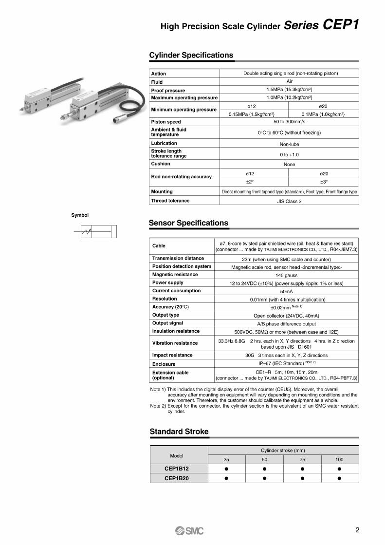
Cylinder Specifications
Double acting single rod (non-rotating piston)
Air
1.5MPa 15.3kgf/cm²
1.0MPa 10.2kgf/cm²
50 to 300mm/s
0°C to 60°C (without freezing)
Non-lube
0 to +1.0
None
Direct mounting front tapped type (standard), Foot type, Front flange type
JIS Class 2
ø12
0.15MPa 1.5kgf/cm²
ø20
0.1MPa 1.0kgf/cm²
ø12
±2°
ø20
±3°
Action
Fluid
Proof pressureMaximum operating pressure
Minimum operating pressure
Piston speed
Ambient & fluid temperature
Lubrication
Stroke length tolerance range
Cushion
Rod non-rotating accuracy
Mounting
Thread tolerance
ø7, 6-core twisted pair shielded wire (oil, heat & flame resistant)(connector ... made by TAJIMI ELECTRONICS CO., LTD., R04-J8M7.3)
Sensor Specifications
Cable
Transmission distance
Position detection system
Magnetic resistance
Power supply
Current consumption
Resolution
Accuracy (20°C)
Output type
Output signal
Insulation resistance
Vibration resistance
Impact resistance
Enclosure
Extension cable(optional)
23m (when using SMC cable and counter)
Magnetic scale rod, sensor head <incremental type>
145 gauss
12 to 24VDC (±10%) (power supply ripple: 1% or less)
50mA
0.01mm (with 4 times multiplication)
±0.02mm Note 1)
Open collector (24VDC, 40mA)
A/B phase difference output
500VDC, 50MΩ or more (between case and 12E)
33.3Hz 6.8G 2 hrs. each in X, Y directions 4 hrs. in Z directionbased upon JIS D1601
30G 3 times each in X, Y, Z directions
IP–67 (IEC Standard) Note 2)
CE1–R 5m, 10m, 15m, 20m(connector ... made by TAJIMI ELECTRONICS CO., LTD., R04-P8F7.3)
Standard Stroke
Model
CEP1B12
CEP1B20
Cylinder stroke (mm)
25
50
75
100
Symbol
Note 1) This includes the digital display error of the counter (CEU5). Moreover, the overall accuracy after mounting on equipment will vary depending on mounting conditions and the environment. Therefore, the customer should calibrate the equipment as a whole.
Note 2) Except for the connector, the cylinder section is the equivalent of an SMC water resistant cylinder.
2
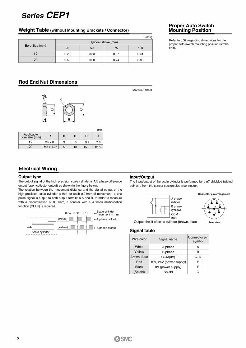
Series CEP1Weight Table (without Mounting Brackets / Connector)
Rod End Nut Dimensions
Applicablebore size (mm)
1220
d
M5 x 0.8
M8 x 1.25
H
3
5
B
8
13
C
9.2
15.0
D
7.8
12.5
(mm)
Bore Size (mm)
12
20
Cylinder stroke (mm)
25
0.29
0.62
50
0.33
0.68
75
0.37
0.74
100
0.41
0.80
Unit: kg
Material: Steel
Output typeThe output signal of the high precision scale cylinder is A/B phase difference output (open collector output) as shown in the figure below.The relation between the movement distance and the signal output of the high precision scale cylinder is that for each 0.04mm of movement a one pulse signal is output to both output terminals A and B. In order to measure with a discrimination of 0.01mm, a counter with a 4 times multiplication function (CEU5) is required.
Input/OutputThe input/output of the scale cylinder is performed by a ø7 shielded twisted pair wire from the sensor section plus a connector.
Electrical Wiring
Signal table
Wire color
White
Yellow
Brown, Blue
Red
Black
(Shield)
Signal name
A phase
B phase
COM(0V)
12V, 24V (power supply)
0V (power supply)
Shield
A
B
C, D
E
F
G
Connector pinsymbol
Connector pin arrangement
Rear view
A
B
DE
F
G
C
H
A phase(white)
B phase(yellow)
Output circuit of scale cylinder (brown, blue)
COM(0V)
0.04
(White)
(Yellow)
Scale cylinder
0.08 0.12 Scale cylindermovement in mm
←A phase output
←B phase output
←
B
C
d
D
H
30°
Refer to p.32 regarding dimensions for the proper auto switch mounting position (stroke end).
Proper Auto Switch Mounting Position
3
Weight Table (without Mounting Brackets / Connector)
Rod End Nut Dimensions
Applicablebore size (mm)
1220
d
M5 x 0.8
M8 x 1.25
H
3
5
B
8
13
C
9.2
15.0
D
7.8
12.5
(mm)
Bore Size (mm)
12
20
Cylinder stroke (mm)
25
0.29
0.62
50
0.33
0.68
75
0.37
0.74
100
0.41
0.80
Unit: kg
Material: Steel
Output typeThe output signal of the high precision scale cylinder is A/B phase difference output (open collector output) as shown in the figure below.The relation between the movement distance and the signal output of the high precision scale cylinder is that for each 0.04mm of movement a one pulse signal is output to both output terminals A and B. In order to measure with a discrimination of 0.01mm, a counter with a 4 times multiplication function (CEU5) is required.
Input/OutputThe input/output of the scale cylinder is performed by a ø7 shielded twisted pair wire from the sensor section plus a connector.
Electrical Wiring
Signal table
Wire color
White
Yellow
Brown, Blue
Red
Black
(Shield)
Signal name
A phase
B phase
COM(0V)
12V, 24V (power supply)
0V (power supply)
Shield
A
B
C, D
E
F
G
Connector pinsymbol
Connector pin arrangement
Rear view
A
B
DE
F
G
C
H
A phase(white)
B phase(yellow)
Output circuit of scale cylinder (brown, blue)
COM(0V)
0.04
(White)
(Yellow)
Scale cylinder
0.08 0.12 Scale cylindermovement in mm
←A phase output
←B phase output
←
B
C
d
D
H
30°
Refer to p.32 regarding dimensions for the proper auto switch mounting position (stroke end).
Proper Auto Switch Mounting Position
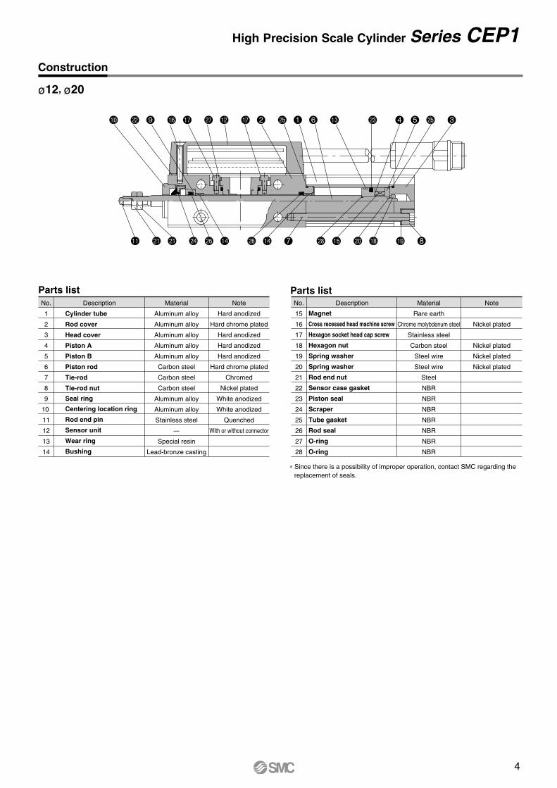
High Precision Scale Cylinder Series CEP1Construction
No.
1
2
3
4
5
6
7
8
9
10
11
12
13
14
Description Material
Aluminum alloy
Aluminum alloy
Aluminum alloy
Aluminum alloy
Aluminum alloy
Carbon steel
Carbon steel
Carbon steel
Aluminum alloy
Aluminum alloy
Stainless steel
–
Special resin
Lead-bronze casting
Note
Hard anodized
Hard chrome plated
Hard anodized
Hard anodized
Hard anodized
Hard chrome plated
Chromed
Nickel plated
White anodized
White anodized
Quenched
With or without connector
Cylinder tube
Rod cover
Head cover
Piston A
Piston B
Piston rod
Tie-rod
Tie-rod nut
Seal ring
Centering location ring
Rod end pin
Sensor unit
Wear ring
Bushing
Parts listParts listNo.
15
16
17
18
19
20
21
22
23
24
25
26
27
28
Description Material
Rare earth
Chrome molybdenum steel
Stainless steel
Carbon steel
Steel wire
Steel wire
Steel
NBR
NBR
NBR
NBR
NBR
NBR
NBR
Note
Nickel plated
Nickel plated
Nickel plated
Nickel plated
Magnet
Cross recessed head machine screw
Hexagon socket head cap screw
Hexagon nut
Spring washer
Spring washer
Rod end nut
Sensor case gasket
Piston seal
Scraper
Tube gasket
Rod seal
O-ring
O-ring
ø12, ø20
bk cm 9 bq br cr bm br 2 cp 1 6 bn cn 4 5 cp 3
bl cl cl co cq bo cq bo 7 cs bp ck bs bt 8
∗ Since there is a possibility of improper operation, contact SMC regarding the replacement of seals.
4
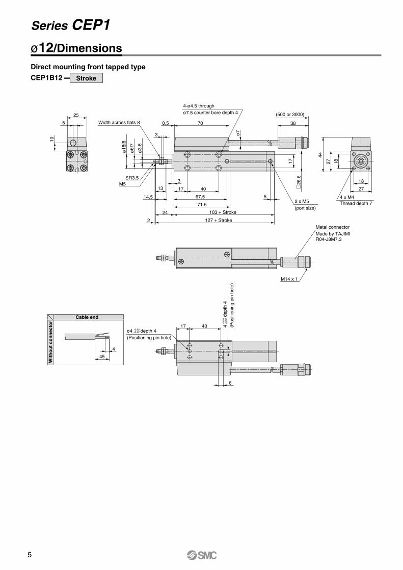
Series CEP1
ø12/DimensionsDirect mounting front tapped type
CEP1B12 Stroke
Cable end
Wit
ho
ut
con
nec
tor
45
4
17
6
40ø4 depth 4(Positioning pin hole)
+0.05+0.02
4
dep
th 4
(Pos
ition
ing
pin
hole
)
+0.
05+
0.02
Metal connectorMade by TAJIMIR04-J8M7.3
M14 x 1
5
25
10
26
.6
17
(500 or 3000)
38
5
71.5
103 + Stroke
127 + Stroke
67.5
4017
3
13
14.5
2
24
ø7
2 x M5(port size)
4-ø4.5 throughø7.5 counter bore depth 4
700.5Width across flats 8
3
ø18
f8
ø6f
7
ø3.
8
SR3.5M5
4 x M4Thread depth 7
27
18
44
27 18
5
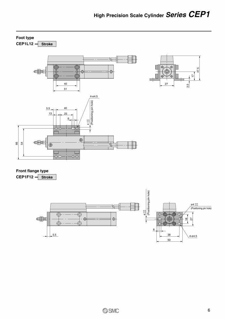
High Precision Scale Cylinder Series CEP1
Foot type
CEP1L12 Stroke
Front flange type
CEP1F12 Stroke
17
3.527
5466
47.5
5.5
13
51
40
40
25
6
2718
5.5 38
6
50
4 (Pos
ition
ing
pin
hole
)
+0.
05+
0.02
4-ø4.5
4 (Pos
ition
ing
pin
hole
)
+0.
05+
0.02
4-ø4.5
ø4(Positioning pin hole)
+0.05+0.02
ø12/DimensionsDirect mounting front tapped type
CEP1B12 Stroke
Cable end
Wit
ho
ut
con
nec
tor
45
4
17
6
40ø4 depth 4(Positioning pin hole)
+0.05+0.02
4
dep
th 4
(Pos
ition
ing
pin
hole
)
+0.
05+
0.02
Metal connectorMade by TAJIMIR04-J8M7.3
M14 x 1
5
25
10
26
.6
17
(500 or 3000)
38
5
71.5
103 + Stroke
127 + Stroke
67.5
4017
3
13
14.5
2
24
ø7
2 x M5(port size)
4-ø4.5 throughø7.5 counter bore depth 4
700.5Width across flats 8
3
ø18
f8
ø6f
7
ø3.
8
SR3.5M5
4 x M4Thread depth 7
27
18
44
27 18
6
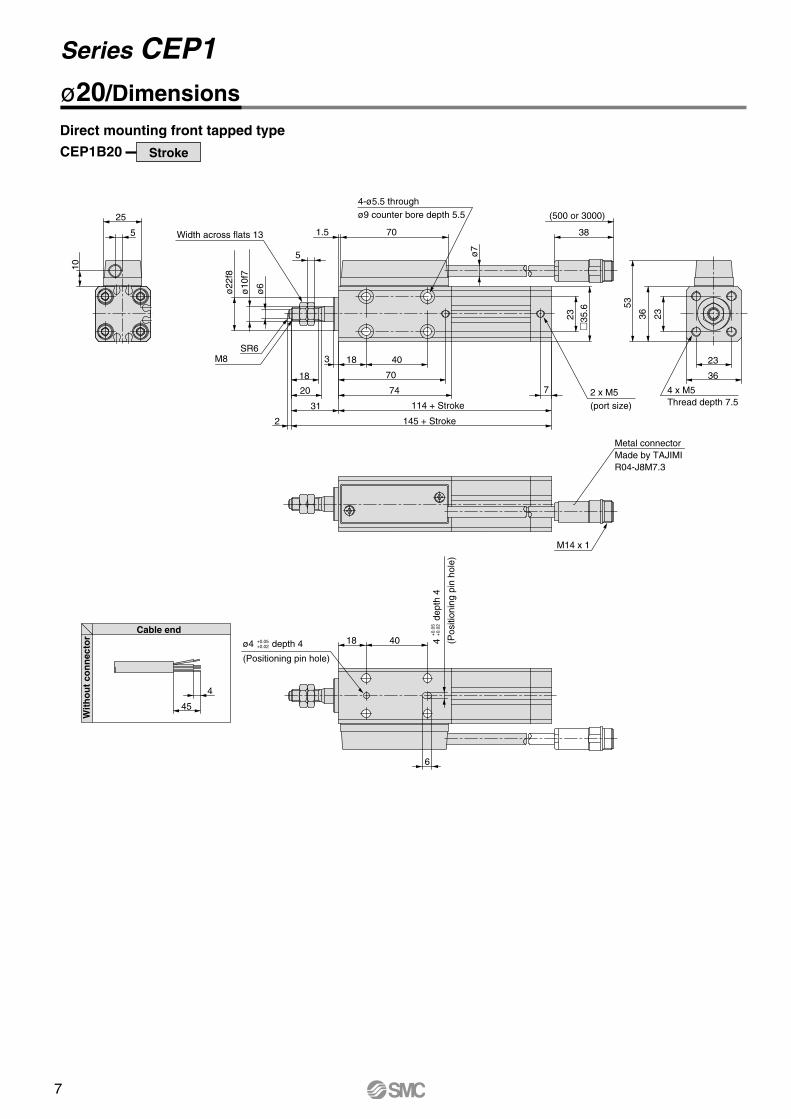
Series CEP1ø20/Dimensions
Cable end
Wit
ho
ut
con
nec
tor
4
45
18 40ø4 depth 4
(Positioning pin hole)
+0.05+0.02
6
4
de
pth
4
(Pos
ition
ing
pin
hole
)
+0.
05+
0.02
Metal connectorMade by TAJIMIR04-J8M7.3
M14 x 1
5
25
10
35
.6
23
(500 or 3000)
38
7 2 x M5(port size)
ø7
74
114 + Stroke
145 + Stroke
70
40183
18
20
2
31
4-ø5.5 throughø9 counter bore depth 5.5
701.5
5
ø22
f8
ø10
f7
ø6
SR6M8
4 x M5Thread depth 7.5
36
23
53
36 23
Width across flats 13
Direct mounting front tapped type
CEP1B20 Stroke
7
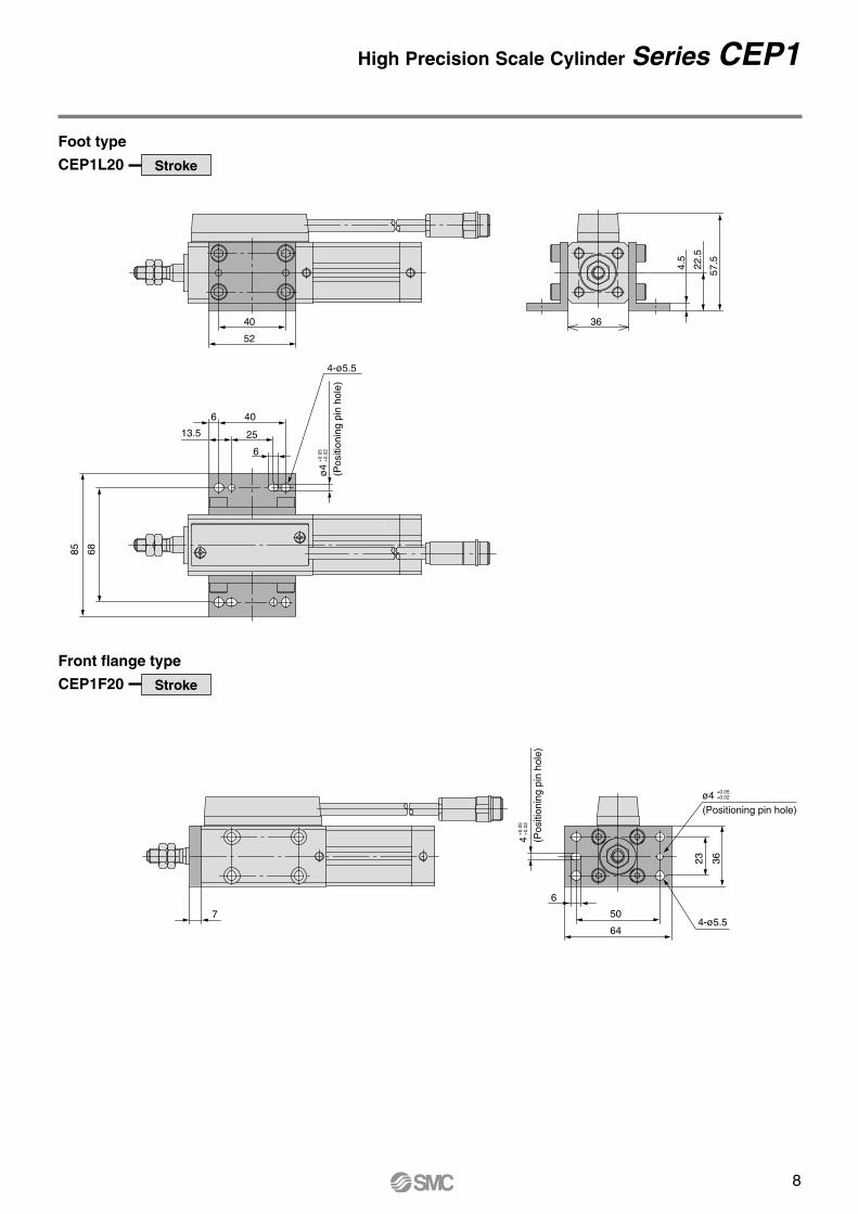
High Precision Scale Cylinder Series CEP1
Foot type
CEP1L20 Stroke
Front flange type
CEP1F20 Stroke22
.5
4.5
57.5
36
6885
52
40
13.5 25
6
406
50
6
64
23 36
ø4
(Pos
ition
ing
pin
hole
)
+0.
05+
0.02
4-ø5.5
4 (Pos
ition
ing
pin
hole
)
+0.
05+
0.02
4-ø5.57
ø4(Positioning pin hole)
+0.05+0.02
ø20/Dimensions
Cable end
Wit
ho
ut
con
nec
tor
4
45
18 40ø4 depth 4
(Positioning pin hole)
+0.05+0.02
6
4
de
pth
4
(Pos
ition
ing
pin
hole
)
+0.
05+
0.02
Metal connectorMade by TAJIMIR04-J8M7.3
M14 x 1
5
25
10
35
.6
23
(500 or 3000)
38
7 2 x M5(port size)
ø7
74
114 + Stroke
145 + Stroke
70
40183
18
20
2
31
4-ø5.5 throughø9 counter bore depth 5.5
701.5
5
ø22
f8
ø10
f7
ø6
SR6M8
4 x M5Thread depth 7.5
36
23
53
36 23
Width across flats 13
Direct mounting front tapped type
CEP1B20 Stroke
8
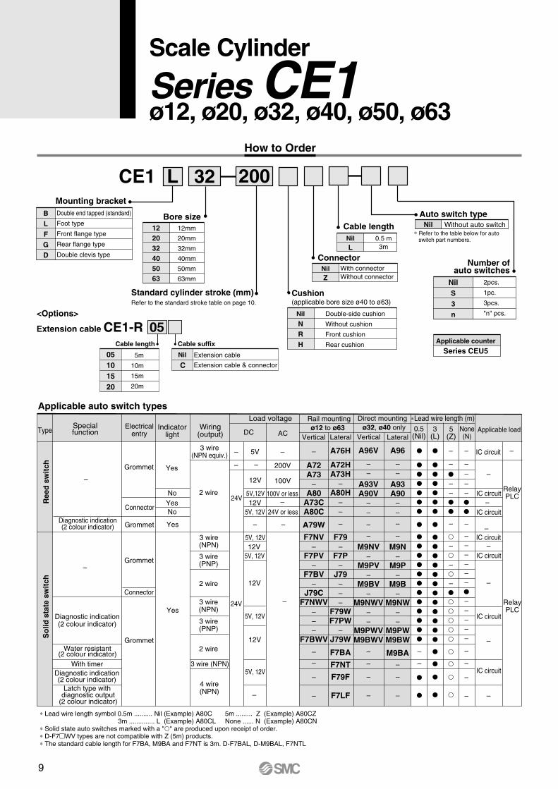
CE1 L 32 200
Double end tapped (standard)
Foot type
Front flange type
Rear flange type
Double clevis type
Mounting bracketBLFGD
12mm
20mm
32mm
40mm
50mm
63mm
Bore size122032405063
Standard cylinder stroke (mm)Refer to the standard stroke table on page 10.
Cushion(applicable bore size ø40 to ø63)
Nil
NRH
Double-side cushion
Without cushion
Front cushion
Rear cushion
With connectorWithout connector
2pcs.
1pc.
3pcs.
"n" pcs.
Auto switch typeNil Without auto switch
Number ofauto switches
NilS
3
n
ConnectorNilZ
How to Order
∗ Refer to the table below for auto switch part numbers.
Applicable auto switch types
∗ Lead wire length symbol 0.5m .......... Nil (Example) A80C 5m ......... Z (Example) A80CZ 3m .............. L (Example) A80CL None ...... N (Example) A80CN ∗ Solid state auto switches marked with a "" are produced upon receipt of order.∗ D-F7WV types are not compatible with Z (5m) products.∗ The standard cable length for F7BA, M9BA and F7NT is 3m. D-F7BAL, D-M9BAL, F7NTL
Ree
d s
wit
chS
olid
sta
te s
wit
ch
TypeSpecialfunction
–
–
Water resistant(2 colour indicator)
With timerDiagnostic indication(2 colour indicator)
Diagnostic indication(2 colour indicator)
Latch type with diagnostic output
(2 colour indicator)
Diagnostic indication(2 colour indicator)
Electricalentry
Grommet
Connector
Grommet
Grommet
Connector
Grommet
Yes
NoYesNo
Yes
Yes
Indicatorlight
Wiring(output)
3 wire(NPN equiv.)
3 wire(NPN)
3 wire(PNP)
3 wire(NPN)
3 wire (NPN)
4 wire(NPN)
3 wire(PNP)
2 wire
2 wire
2 wire
DC AC
Load voltage
–
–
5V –
–
–
–
200V
100V
5V, 12V
5V, 12V
5V, 12V
5V, 12V
5V, 12V
5V,12V 100V or less
24V or less12V
12V
12V
12V
12V
–
–
–
24V
24V
Vertical Lateral
–
A72A73
–A80
A73CA80C
A79W
F7NV–
F7PV–
F7BV–
J79CF7NWV
–––
F7BWV
–
–
–
–
A76H
A72HA73H
–A80H
––
–
F79–
F7P–
J79–––
F79WF7PW
–J79W
F7BA
F7NT
F79F
F7LF
Vertical Lateral
Direct mounting
A96V
––
A93VA90V
––
–
–
M9NV–
M9PV–
M9BV–
M9NWV––
M9PWVM9BWV
–
–
–
–
A96
––
A93A90
––
–
–
M9N–
M9P–
M9B–
M9NW––
M9PWM9BW
M9BA–
–
–
RelayPLC
RelayPLC
IC circuit
IC circuit
IC circuit
IC circuit
IC circuit
IC circuit
IC circuit
–
–
–
–
–
–
–
–
–
–
–
–
––
–
–––
–
––––
–
–––––––––––
–
–
–
–
0.5(Nil)
3(L)
5(Z)
None(N)
∗Lead wire length (m)
Applicable load
Rail mountingø12 to ø63 ø32, ø40 only
Applicable counter
Series CEU5
<Options>
Extension cable CE1-RCable length
05101520
5m
10m
15m
20m
Cable suffix
Nil
CExtension cable
Extension cable & connector
05
0.5 m3m
Cable lengthNilL
Scale Cylinder
Series CE1ø12, ø20, ø32, ø40, ø50, ø63
9
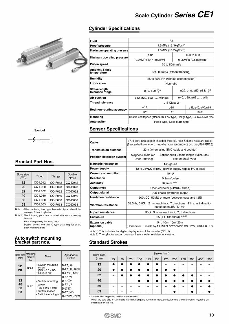
Scale Cylinder Series CE1Cylinder Specifications
Air
1.5MPa 15.3kgf/cm²
1.0MPa 10.2kgf/cm²
70 to 500mm/s
0°C to 60°C (without freezing)
25 to 85% RH (without condensation)
Non-lube
JIS Class 2
ø20
±1°
Double end tapped (standard), Foot type, Flange type, Double clevis type
Reed type, Solid state type
ø12
0.07MPa 0.71kgf/cm²
ø20 to ø63
0.05MPa 0.51kgf/cm²
ø12
±2°ø32, ø40, ø50, ø63
±0.8°
Fluid
Proof pressure
Maximum operating pressure
Minimum operating pressure
Piston speed
Ambient & fluid temperature
Humidity
Lubrication
Stroke length tolerance range
Air cushion
Thread tolerance
Rod non-rotating accuracy
Mounting
Auto switch
ø12, ø20:
ø12, ø20, ø32 ...... without
+1.00 ø32, ø40, ø50, ø63:
ø40, ø50, ø63 ...... with
+1.60
ø7, 6-core twisted pair shielded wire (oil, heat & flame resistant cable)(Standard with connector ... made by TAJIMI ELECTRONICS CO., LTD., R04-J8M7.3)
33.3Hz, 6.8G 2 hrs. each in X, Y directions 4 hrs. in Z directionbased upon JIS D1601
5m, 10m, 15m, 20m(Connector ... made by TAJIMI ELECTRONICS CO., LTD., R04-P8F7.3)
Sensor Specifications
Cable
Transmission distance
Position detection system
Magnetic resistance
Power supply
Current consumption
Resolution
Accuracy
Output type
Output signal
Insulation resistance
Vibration resistance
Impact resistance
Enclosure
23m (when using SMC cable and counter)
145 gauss
12 to 24VDC (±10%) (power supply ripple: 1% or less)
40mA
0.1mm/pulse
±0.2mm Note 1)
Open collector (24VDC, 40mA)
A/B phase difference output
500VDC, 50MΩ or more (between case and 12E)
30G 3 times each in X, Y, Z directions
IP65 (IEC Standard) Note 2)
Extension cable(optional)
Magnetic scale rod <non-rotating>
Sensor head <cable length 50cm, 3m><incremental type>
Standard Strokes
12
20
32
40
50
63
–
–
–
–
25
–
–
–
–
–
–
50
–
–
–
–
–
–
–
–
–
10075
–
125
–
–
150
–
–
–
–
–
–
–
–
–
–
–
–
175 200 250 300 400 500
Stroke (mm)Bore size(mm)
Symbol
122032405063
CQ-L012
CQ-L020
CQ-L032
CQ-L040
CQ-L050
CQ-L063
CQ-F012
CQ-F020
CQ-F032
CQ-F040
CQ-F050
CQ-F063
CQ-D012
CQ-D020
CQ-D032
CQ-D040
CQ-D050
CQ-D063
∗Foot FlangeBore size
(mm)Doubleclevis
Note 1) When ordering foot type brackets, 2pcs. should be arranged for each cylinder.
Note 2) The following parts are included with each mounting bracket.Foot, Flange/Body mounting boltsDouble clevis/Clevis pin, C type snap ring for shaft, Body mounting bolts
Bracket Part Nos.
1220
32405063
Bore size(mm)
Mountingbracket
no.
BQ-1
BQ-2
Note
• Switch mounting screw (M3 x 0.5 x 8l)• Square nut
• Switch mounting screw (M3 x 0.5 x 10l)• Switch spacer• Switch mounting nut
Applicableswitch
D-A7, A8D-A7H, A80HD-A73C, A80CD-A79WD-F7VD-F7, J7D-J79CD-F7WVD-F79W, J79W
Auto switch mounting bracket part nos.
∗ Contact SMC regarding non-standard strokes. When the bore size is 12mm and the stroke length is 100mm or more, particular care should be taken regarding an offset load on the rod.
Note1 ) This includes the digital display error of the counter (CEU1).Note 2) The cylinder section does not have a water resistant enclosure.
10
Series CE1
Part No.
NTJ-015ANT-02 NT-04 NT-05
Applicablebore size
(mm)
12
20
32, 40
50, 63
d
M5
M8
M14 x 1.5
M18 x 1.5
H
4
5
8
11
B
8
13
22
27
C
9.2
15.0
25.4
31.2
D
7.8
12.5
21.0
26
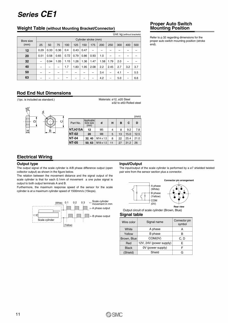
Weight Table (without Mounting Bracket/Connector)
12
20
32
40
50
63
0.29
0.51
–
–
–
–
25
0.33
0.58
0.94
–
–
–
50
0.4
0.72
1.15
1.7
100
0.36
0.65
1.05
–
–
–
75
0.43
0.79
1.26
1.83
–
–
125
0.47
0.86
1.36
1.95
–
–
150
–
0.93
1.47
2.08
–
–
175
–
1.0
1.58
2.2
3.4
4.2
200
–
–
1.79
2.45
–
–
250
–
–
–
3.2
–
–
400
–
–
2.0
2.7
4.1
5.0
300
–
–
–
3.7
5.5
6.6
500
Cylinder stroke (mm)Bore size(mm)
Unit: kg (without brackets)
Materials: ø12, ø20 Steel ø32 to ø63 Rolled steel
Rod End Nut Dimensions(1pc. is included as standard.)
(mm)
Input/OutputThe input/output of the scale cylinder is performed by a ø7 shielded twisted pair wire from the sensor section plus a connector.
Electrical Wiring
Signal table
Wire color
White
Yellow
Brown, Blue
Red
Black
(Shield)
Signal name
A phase
B phase
COM(0V)
12V, 24V (power supply)
0V (power supply)
Shield
A
B
C, D
E
F
G
Connector pinsymbol
Connector pin arrangement
Rear view
A
B
DE
F
G
C
H
Output typeThe output signal of the scale cylinder is A/B phase difference output (open collector output) as shown in the figure below.The relation between the movement distance and the signal output of the scale cylinder is that for each 0.1mm of movement a one pulse signal is output to both output terminals A and B.Furthermore, the maximum response speed of the sensor for the scale cylinder is at a maximum cylinder speed of 1500mm/s (15kcps).
B
C
d
D
H
30°
A phase(White)
B phase(Yellow)
Output circuit of scale cylinder (Brown, Blue)
COM(0V)0.1(White)
(Yellow)
Scale cylinder
0.2 0.3 Scale cylindermovement in mm
←A phase output
←B phase output
←
–
–
Refer to p.32 regarding dimensions for the proper auto switch mounting position (stroke end).
Proper Auto Switch Mounting Position
11
12
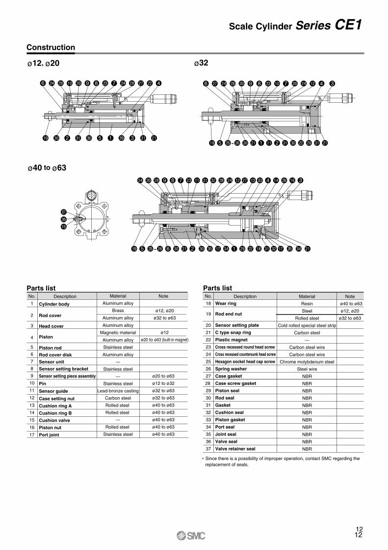
Scale Cylinder Series CE1Construction
No.
1
2
3
4
5
6
7
8
9
10
11
12
13
14
15
16
17
Description Material
Aluminum alloy
Brass
Aluminum alloy
Aluminum alloy
Magnetic material
Aluminum alloy
Stainless steel
Aluminum alloy
–
Stainless steel
–
Stainless steel
Lead-bronze casting
Carbon steel
Rolled steel
Rolled steel
–
Rolled steel
Stainless steel
Note
ø12, ø20
ø32 to ø63
ø12
ø20 to ø63 (built-in magnet)
ø20 to ø63
ø12 to ø32
ø32 to ø63
ø32 to ø63
ø40 to ø63
ø40 to ø63
ø40 to ø63
ø40 to ø63
ø40 to ø63
Cylinder body
Rod cover
Head cover
Piston
Piston rod
Rod cover disk
Sensor unit
Sensor setting bracket
Sensor setting piece assembly
Pin
Sensor guide
Case setting nut
Cushion ring A
Cushion ring B
Cushion valve
Piston nut
Port joint
Parts list Parts listNo.
18
19
20
21
22
23
24
25
26
27
28
29
30
31
32
33
34
35
36
37
Description Material
Resin
Steel
Rolled steel
Cold rolled special steel strip
Carbon steel
–
Carbon steel wire
Carbon steel wire
Chrome molybdenum steel
Steel wire
NBR
NBR
NBR
NBR
NBR
NBR
NBR
NBR
NBR
NBR
NBR
Note
ø40 to ø63
ø12, ø20
ø32 to ø63
Wear ring
Rod end nut
Sensor setting plate
C type snap ring
Plastic magnet
Cross recessed round head screw
Cross recessed countersunk head screw
Hexagon socket head cap screw
Spring washer
Case gasket
Case screw gasket
Piston seal
Rod seal
Gasket
Cushion seal
Piston gasket
Port seal
Joint seal
Valve seal
Valve retainer seal
ø40 to ø63
ø32
dr
dqbp
ø12, ø20
bt 5 cp-cq dk cl 1 bl 2 dl dk cm ct dl cl
bt 5 cp-cq 6 dk cl 2 dk dp br do 1 ct cm bs dldmbr dp do cl
6 cr co cs ck 9 8 cn bk 7 cs co bm 4 3
co ck cs 9 8 7 cn bl dl dm cs co bmcr bndn 4 bo cq bq 3
∗ Since there is a possibility of improper operation, contact SMC regarding the replacement of seals.
bt dk 2 dl dk 5 1 ct 3 dl cl
6 co cs bk ck 9 8 cn 7 co cs cr cm 4
Part No.
NTJ-015ANT-02 NT-04 NT-05
Applicablebore size
(mm)
12
20
32, 40
50, 63
d
M5
M8
M14 x 1.5
M18 x 1.5
H
4
5
8
11
B
8
13
22
27
C
9.2
15.0
25.4
31.2
D
7.8
12.5
21.0
26
Weight Table (without Mounting Bracket/Connector)
12
20
32
40
50
63
0.29
0.51
–
–
–
–
25
0.33
0.58
0.94
–
–
–
50
0.4
0.72
1.15
1.7
100
0.36
0.65
1.05
–
–
–
75
0.43
0.79
1.26
1.83
–
–
125
0.47
0.86
1.36
1.95
–
–
150
–
0.93
1.47
2.08
–
–
175
–
1.0
1.58
2.2
3.4
4.2
200
–
–
1.79
2.45
–
–
250
–
–
–
3.2
–
–
400
–
–
2.0
2.7
4.1
5.0
300
–
–
–
3.7
5.5
6.6
500
Cylinder stroke (mm)Bore size(mm)
Unit: kg (without brackets)
Materials: ø12, ø20 Steel ø32 to ø63 Rolled steel
Rod End Nut Dimensions(1pc. is included as standard.)
(mm)
Input/OutputThe input/output of the scale cylinder is performed by a ø7 shielded twisted pair wire from the sensor section plus a connector.
Electrical Wiring
Signal table
Wire color
White
Yellow
Brown, Blue
Red
Black
(Shield)
Signal name
A phase
B phase
COM(0V)
12V, 24V (power supply)
0V (power supply)
Shield
A
B
C, D
E
F
G
Connector pinsymbol
Connector pin arrangement
Rear view
A
B
DE
F
G
C
H
Output typeThe output signal of the scale cylinder is A/B phase difference output (open collector output) as shown in the figure below.The relation between the movement distance and the signal output of the scale cylinder is that for each 0.1mm of movement a one pulse signal is output to both output terminals A and B.Furthermore, the maximum response speed of the sensor for the scale cylinder is at a maximum cylinder speed of 1500mm/s (15kcps).
B
C
d
D
H
30°
A phase(White)
B phase(Yellow)
Output circuit of scale cylinder (Brown, Blue)
COM(0V)0.1(White)
(Yellow)
Scale cylinder
0.2 0.3 Scale cylindermovement in mm
←A phase output
←B phase output
←
–
–
Refer to p.32 regarding dimensions for the proper auto switch mounting position (stroke end).
Proper Auto Switch Mounting Position
12
Series CE1
13
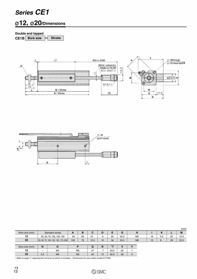
ø12, ø20/Dimensions
CE1B Bore size StrokeDouble end tapped
Bore size (mm)
1220
(mm)
Standard stroke
25, 50, 75, 100, 125, 150
25, 50, 75, 100, 125, 150, 175, 200
94
106
Bore size (mm)
1220
–
5.5
M4
M6
M5
M5
69
78
15
15.5
6
10
25
36
42.5
53.5
47
50
7
15
53.5
62.5
22
36
7
5
M5
M8
16
10
5.2
8
25
28
15.5
25.5
A
N O P
B C D E G
Q R ∗T V Y
H I K L M
∗ Refer to page 11 regarding the rod end nut which is included. ∗ Dimensions for auto switch model D-F79W.
13
Scale Cylinder Series CE1
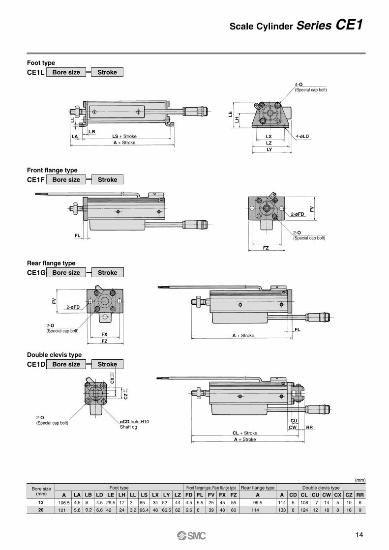
Bore size(mm)
12
20
(mm)
Foot type Front flange type, Rear flange type Double clevis type
A106.5
121
LA4.5
5.8
LB8
9.2
LD4.5
6.6
LE29.5
42
LH17
24
LL2
3.2
LS85
96.4
LX34
48
LY52
66.5
LZ44
62
FD4.5
6.6
FL5.5
8
FV25
39
FX45
48
FZ55
60
Rear flange type
A99.5
114
A114
133
CD5
8
CL108
124
CU 7
12
CW14
18
CX5
8
CZ10
16
RR6
9
CE1L Bore size Stroke
Foot type
CE1F Bore size Stroke
Front flange type
CE1G Bore size Stroke
Rear flange type
CE1D Bore size Stroke
Double clevis type
4-øLD
2-øFD
4-O(Special cap bolt)
2-O(Special cap bolt)
LE
LH
FV
FZ
2-øFD
2-O(Special cap bolt)
FV
FZ
FL
LALB
LZLY
LS + StrokeA + Stroke
CL + StrokeA + Stroke
A + StrokeFL
RRCU
CW
2-O(Special cap bolt) øCD hole H10
Shaft dg
CZ
–0.1
–0.3
CX
+0.
4+
0.2
LX
LL
FX
ø12, ø20/Dimensions
CE1B Bore size StrokeDouble end tapped
Bore size (mm)
1220
(mm)
Standard stroke
25, 50, 75, 100, 125, 150
25, 50, 75, 100, 125, 150, 175, 200
94
106
Bore size (mm)
1220
–
5.5
M4
M6
M5
M5
69
78
15
15.5
6
10
25
36
42.5
53.5
47
50
7
15
53.5
62.5
22
36
7
5
M5
M8
16
10
5.2
8
25
28
15.5
25.5
A
N O P
B C D E G
Q R ∗T V Y
H I K L M
∗ Refer to page 11 regarding the rod end nut which is included. ∗ Dimensions for auto switch model D-F79W.
14
32405063
(mm)
A148
195.2
215.7
219.2
LA5.8
7
8
9
LB11.2
11.2
14.7
16.2
LD6.6
6.6
9
11
LE52.5
59
71
84.5
LH30
33
39
46
LS112.4
158.4
173.4
177.4
LT65
71.5
83.5
97
LX57
64
79
95
LY72.5
79.5
94
109.5
LZ71
78
95
113
FD5.5
5.5
6.6
9
FG69.5
76.5
91
107
FL8
8
9
9
FT59
65.5
78
91
FV48
54
67
80
FX56
62
76
92
FZ65
72
89
108
M34
40
50
60
A139
185
202
203
A161
209
235
238
CD10
10
14
14
CL151
199
221
224
CU14
14
20
20
CW20
22
28
30
CX18
18
22
22
CZ36
36
44
44
RR10
10
14
14
T57.5
64.5
76.5
89.5
Bore size(mm)
Foot type Front flange type, Rear flange typeRear flange
type Double clevis type
∗ Dimensions for auto switch model D-F79W.
CE1L Bore size Stroke
Foot type
CE1F Bore size Stroke
Front flange type
CE1G Bore size Stroke
Rear flange type
CE1D Bore size Stroke
Double clevis type
4-O(Special cap bolt)4-øLD
A + Stroke
4-øFD
øCD hole H10
Shaft d9
FVM F
T
FX
FZ
FG
LXLZ
LY
CW RR
CU
FLFX
FZ
FG
3.2
FVM F
T
LBLA
LH
LE LT
CX+0
.4+0
.2
CZ
–0.1
–0.3
4-øFD
4-O(Special cap bolt)
4-O
(Special cap bolt)
4-O
A + Stroke
A + Stroke
LS + Stroke
A + Stroke
CL + StrokeT
∗ ∗
FL
Series CE1
I
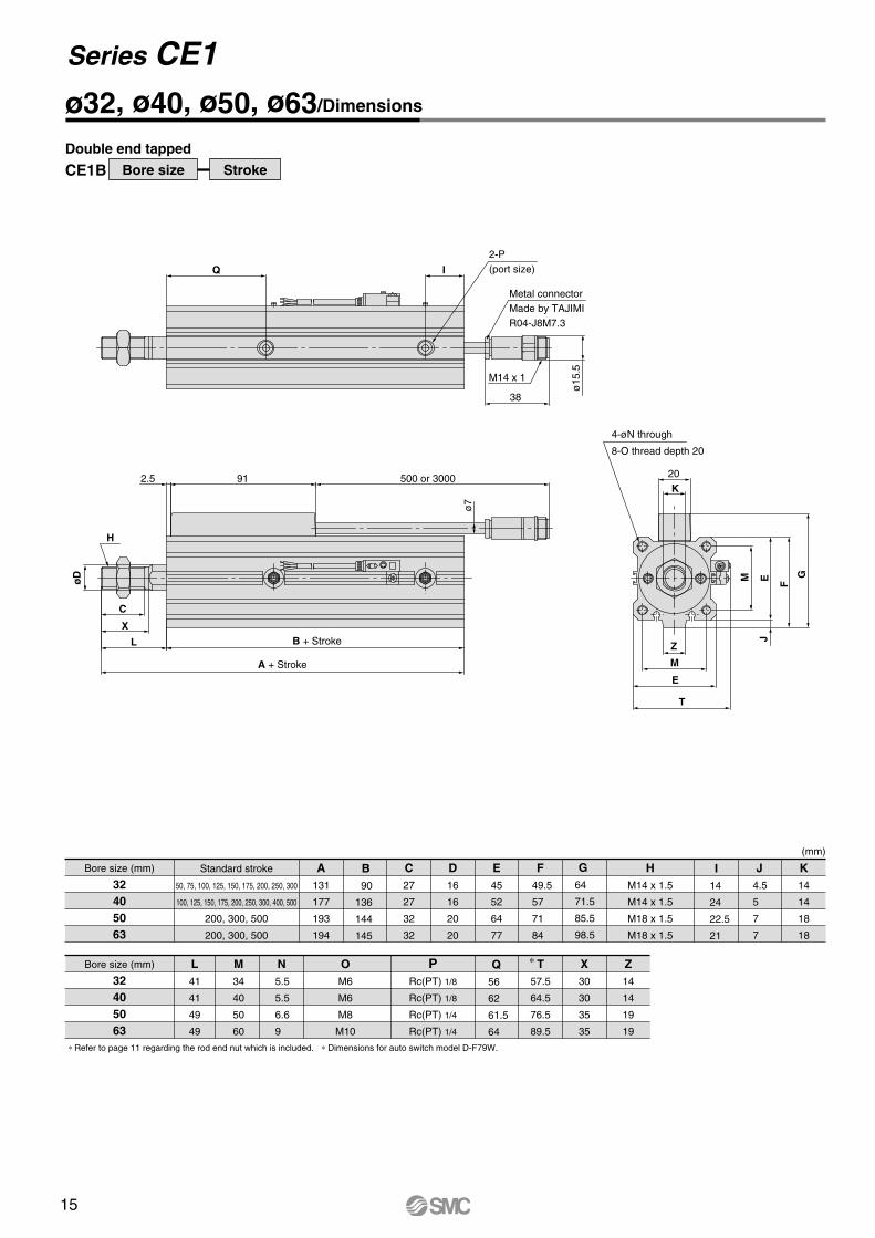
ø32, ø40, ø50, ø63/Dimensions
CE1B Bore size Stroke
Double end tapped
Bore size (mm)
32405063
(mm)
Standard stroke
50, 75, 100, 125, 150, 175, 200, 250, 300
100, 125, 150, 175, 200, 250, 300, 400, 500
200, 300, 500
200, 300, 500
A131
177
193
194
B 90
136
144
145
C27
27
32
32
D16
16
20
20
E45
52
64
77
F49.5
57
71
84
G64
71.5
85.5
98.5
I14
24
22.5
21
J4.5
5
7
7
K14
14
18
18
Bore size (mm)
32405063
L41
41
49
49
M34
40
50
60
N 5.5
5.5
6.6
9
OM6
M6
M8
M10
PRc(PT) 1/8
Rc(PT) 1/8
Rc(PT) 1/4
Rc(PT) 1/4
Q56
62
61.5
64
T57.5
64.5
76.5
89.5
X30
30
35
35
Z14
14
19
19
HM14 x 1.5
M14 x 1.5
M18 x 1.5
M18 x 1.5
∗ Refer to page 11 regarding the rod end nut which is included. ∗ Dimensions for auto switch model D-F79W.
20
4-øN through
8-O thread depth 20
K
Z
M
E
T
G
øD M E
J
F
Metal connectorMade by TAJIMIR04-J8M7.3
2-P(port size)
A + Stroke
B + Stroke
2.5 91 500 or 3000
38
M14 x 1
Q
L
X
C
H
ø15
.5
ø7
∗
15
Scale Cylinder Series CE1
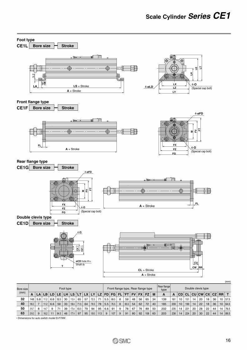
32405063
(mm)
A148
195.2
215.7
219.2
LA5.8
7
8
9
LB11.2
11.2
14.7
16.2
LD6.6
6.6
9
11
LE52.5
59
71
84.5
LH30
33
39
46
LS112.4
158.4
173.4
177.4
LT65
71.5
83.5
97
LX57
64
79
95
LY72.5
79.5
94
109.5
LZ71
78
95
113
FD5.5
5.5
6.6
9
FG69.5
76.5
91
107
FL8
8
9
9
FT59
65.5
78
91
FV48
54
67
80
FX56
62
76
92
FZ65
72
89
108
M34
40
50
60
A139
185
202
203
A161
209
235
238
CD10
10
14
14
CL151
199
221
224
CU14
14
20
20
CW20
22
28
30
CX18
18
22
22
CZ36
36
44
44
RR10
10
14
14
T57.5
64.5
76.5
89.5
Bore size(mm)
Foot type Front flange type, Rear flange typeRear flange
type Double clevis type
∗ Dimensions for auto switch model D-F79W.
CE1L Bore size Stroke
Foot type
CE1F Bore size Stroke
Front flange type
CE1G Bore size Stroke
Rear flange type
CE1D Bore size Stroke
Double clevis type
4-O(Special cap bolt)4-øLD
A + Stroke
4-øFD
øCD hole H10
Shaft d9
FVM F
T
FX
FZ
FG
LXLZ
LY
CW RR
CU
FLFX
FZ
FG
3.2
FVM F
T
LBLA
LH
LE LT
CX+0
.4+0
.2
CZ
–0.1
–0.3
4-øFD
4-O(Special cap bolt)
4-O
(Special cap bolt)
4-O
A + Stroke
A + Stroke
LS + Stroke
A + Stroke
CL + StrokeT
∗ ∗
FL
I
ø32, ø40, ø50, ø63/Dimensions
CE1B Bore size Stroke
Double end tapped
Bore size (mm)
32405063
(mm)
Standard stroke
50, 75, 100, 125, 150, 175, 200, 250, 300
100, 125, 150, 175, 200, 250, 300, 400, 500
200, 300, 500
200, 300, 500
A131
177
193
194
B 90
136
144
145
C27
27
32
32
D16
16
20
20
E45
52
64
77
F49.5
57
71
84
G64
71.5
85.5
98.5
I14
24
22.5
21
J4.5
5
7
7
K14
14
18
18
Bore size (mm)
32405063
L41
41
49
49
M34
40
50
60
N 5.5
5.5
6.6
9
OM6
M6
M8
M10
PRc(PT) 1/8
Rc(PT) 1/8
Rc(PT) 1/4
Rc(PT) 1/4
Q56
62
61.5
64
T57.5
64.5
76.5
89.5
X30
30
35
35
Z14
14
19
19
HM14 x 1.5
M14 x 1.5
M18 x 1.5
M18 x 1.5
∗ Refer to page 11 regarding the rod end nut which is included. ∗ Dimensions for auto switch model D-F79W.
20
4-øN through
8-O thread depth 20
K
Z
M
E
T
G
øD M E
J
F
Metal connectorMade by TAJIMIR04-J8M7.3
2-P(port size)
A + Stroke
B + Stroke
2.5 91 500 or 3000
38
M14 x 1
Q
L
X
C
H
ø15
.5
ø7
∗
16
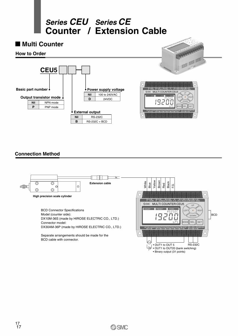
Series CEU Series CECounter / Extension Cable
17
How to Order
Connection Method
Multi Counter
CEU5
Power supply voltage
External outputNil
BRS-232C
RS-232C + BCD
Nil
D100 to 240VAC
24VDCOutput transistor modeNil
PNPN mode
PNP mode
Basic part numberMULTI COUNTER:CEU5
A COM COM COMB DC12V GND F.G. R.S. HOLD BANK1 BANK2
COM S.STOPOUT1OUT2OUT3OUT4OUT5AC100~240V
COUNT PRESET FUNC.
SD SGRD RS-232C
UP
LEFT RIGHT
DOWN
SEL. SETMODE
MULTI COUNTER:CEU5 A COM COM COMB DC12V GND F.G. R.S. HOLD BANK1 BANK2
COM S.STOPOUT1OUT2OUT3OUT4OUT5AC100~240V
COUNT PRESET FUNC.
SD SGRD RS-232C
UP
LEFT RIGHT
DOWN
SEL. SETMODE
Whi
te
Blu
e
Yel
low
Bro
wn
Red
Bla
ck
F.G
.
BCD
• OUT1 to OUT 5 • OUT1 to OUT20 (bank switching) • Binary output (31 points)
RS-232C
BCD Connector SpecificationsModel (counter side):DX10M-36S (made by HIROSE ELECTRIC CO., LTD.)Connector model:DX30AM-36P (made by HIROSE ELECTRIC CO., LTD.)
Separate arrangements should be made for theBCD cable with connector.
High precision scale cylinder
Extension cable
17
18
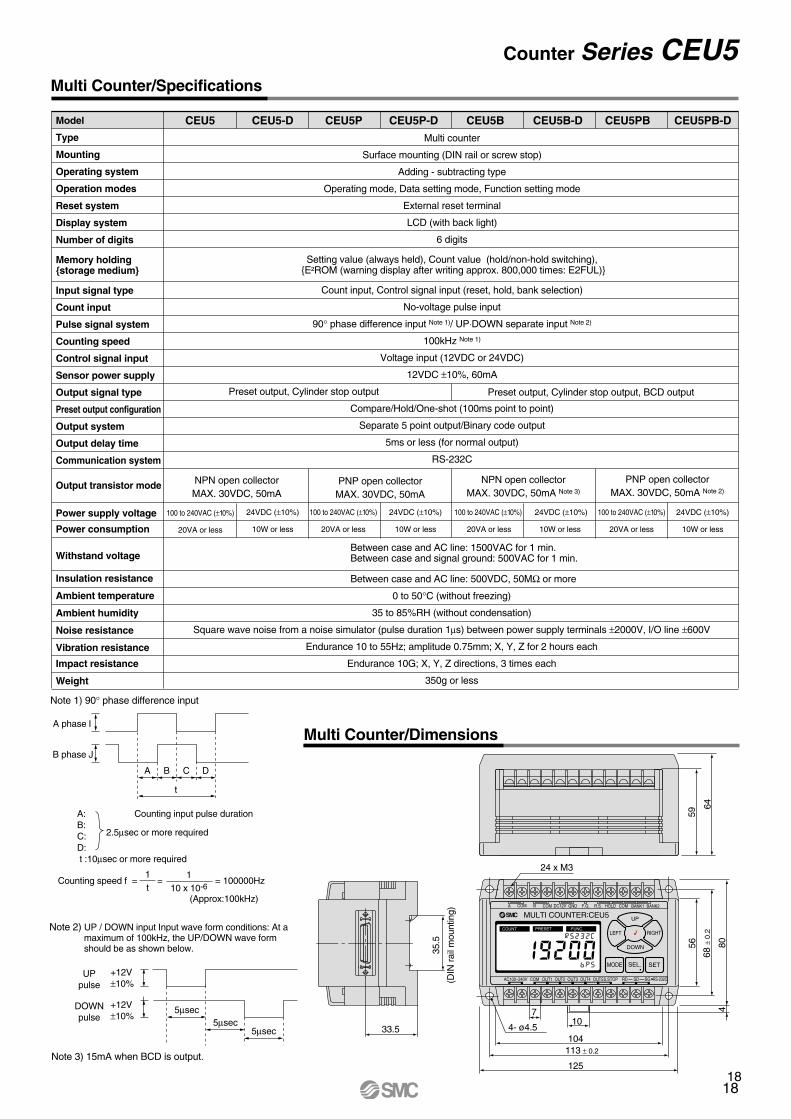
Counter Series CEU5
Model
Type
Mounting
Operating system
Operation modes
Reset system
Display system
Number of digits
Memory holdingstorage medium
Input signal type
Count input
Pulse signal system
Counting speed
Control signal input
Sensor power supply
Output signal type
Preset output configuration
Output system
Output delay time
Communication system
Output transistor mode
Power supply voltage
Power consumption
Withstand voltage
Insulation resistance
Ambient temperature
Ambient humidity
Noise resistance
Vibration resistance
Impact resistance
Weight
CEU5 CEU5-D CEU5P CEU5P-D CEU5B CEU5B-D CEU5PB CEU5PB-D
Multi counter
Surface mounting (DIN rail or screw stop)
Adding - subtracting type
Operating mode, Data setting mode, Function setting mode
External reset terminal
LCD (with back light)
6 digits
Setting value (always held), Count value (hold/non-hold switching), E²ROM (warning display after writing approx. 800,000 times: E2FUL)
Count input, Control signal input (reset, hold, bank selection)
No-voltage pulse input
90° phase difference input Note 1)/ UP⋅DOWN separate input Note 2)
100kHz Note 1)
Voltage input (12VDC or 24VDC)
12VDC ±10%, 60mA
Compare/Hold/One-shot (100ms point to point)
Separate 5 point output/Binary code output
5ms or less (for normal output)
RS-232C
NPN open collectorMAX. 30VDC, 50mA
NPN open collectorMAX. 30VDC, 50mA Note 3)
PNP open collectorMAX. 30VDC, 50mA
PNP open collectorMAX. 30VDC, 50mA Note 2)
100 to 240VAC (±10%)
20VA or less
24VDC (±10%)
10W or less
100 to 240VAC (±10%)
20VA or less
24VDC (±10%)
10W or less
100 to 240VAC (±10%)
20VA or less
24VDC (±10%)
10W or less
100 to 240VAC (±10%)
20VA or less
24VDC (±10%)
10W or less
0 to 50°C (without freezing)
35 to 85%RH (without condensation)
Square wave noise from a noise simulator (pulse duration 1µs) between power supply terminals ±2000V, I/O line ±600V
Endurance 10 to 55Hz; amplitude 0.75mm; X, Y, Z for 2 hours each
Endurance 10G; X, Y, Z directions, 3 times each
350g or less
Note 1) 90° phase difference input
Note 3) 15mA when BCD is output.
A:B:C:D: t :10µsec or more required
Counting input pulse duration
Counting speed f = = = 100000Hz
Between case and AC line: 1500VAC for 1 min.Between case and signal ground: 500VAC for 1 min.
Between case and AC line: 500VDC, 50MΩ or more
Preset output, Cylinder stop output, BCD outputPreset output, Cylinder stop output
MULTI COUNTER:CEU5 A COM COM COMB DC12V GND F.G. R.S. HOLD BANK1 BANK2
COM S.STOPOUT1 OUT2 OUT3 OUT4 OUT5AC100~240V
COUNT PRESET FUNC.
SD SGRD RS-232C
UP
LEFT RIGHT
DOWN
SEL. SETMODE
104
107
4- ø4.533.5
125
59
64
56
68 ±
0.2
804
A
I
J
B
t
C D
2.5µsec or more required
1t
110 x 10-6
(Approx:100kHz)
A phase
B phase
5µsec5µsec
5µsec
+12V±10%
UPpulse
+12V±10%
DOWNpulse
24 x M3
113 ± 0.2
35.5
(DIN
rai
l mou
ntin
g)
Multi Counter/Dimensions
Multi Counter/Specifications
Note 2) UP / DOWN input Input wave form conditions: At a maximum of 100kHz, the UP/DOWN wave form should be as shown below.
18
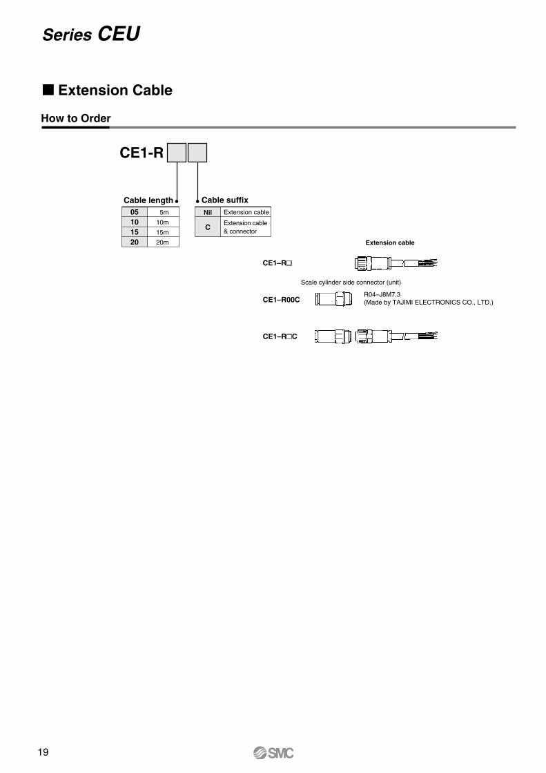
Series CEU
How to Order
CE1-R
Cable length05101520
5m
10m
15m
20m
Cable suffixNil
C
Extension cable
Extension cable& connector
R04–J8M7.3 (Made by TAJIMI ELECTRONICS CO., LTD.)
CE1–R
Scale cylinder side connector (unit)
Extension cable
Extension Cable
CE1–RC
CE1–R00C
19
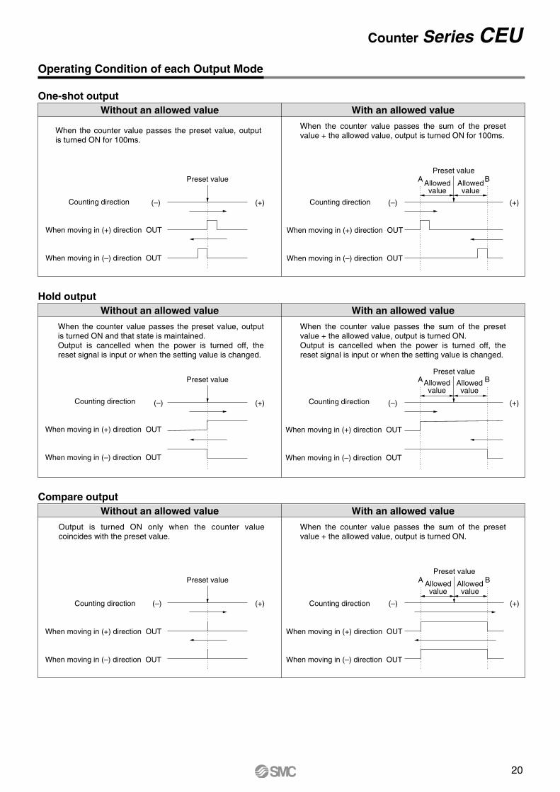
Counter Series CEUOperating Condition of each Output Mode
One-shot outputWith an allowed valueWithout an allowed value
When the counter value passes the preset value, output is turned ON for 100ms.
When the counter value passes the sum of the preset value + the allowed value, output is turned ON for 100ms.
Counting direction
When moving in (+) direction OUT
When moving in (–) direction OUT
Hold outputWith an allowed valueWithout an allowed value
When the counter value passes the preset value, output is turned ON and that state is maintained.Output is cancelled when the power is turned off, the reset signal is input or when the setting value is changed.
When the counter value passes the sum of the preset value + the allowed value, output is turned ON.Output is cancelled when the power is turned off, the reset signal is input or when the setting value is changed.
Compare outputWith an allowed valueWithout an allowed value
Output is turned ON only when the counter value coincides with the preset value.
When the counter value passes the sum of the preset value + the allowed value, output is turned ON.
(+)(–)
Preset value
Counting direction
When moving in (+) direction OUT
When moving in (–) direction OUT
(+)(–)
Preset value
Counting direction
When moving in (+) direction OUT
When moving in (–) direction OUT
(+)(–)
Preset value
Counting direction
When moving in (+) direction OUT
When moving in (–) direction OUT
(+)(–)
Preset value
Allowedvalue
Allowedvalue
A B
Counting direction
When moving in (+) direction OUT
When moving in (–) direction OUT
(+)(–)
Preset value
Allowedvalue
Allowedvalue
A B
Counting direction
When moving in (+) direction OUT
When moving in (–) direction OUT
(+)(–)
Preset value
Allowedvalue
Allowedvalue
A B
How to Order
CE1-R
Cable length05101520
5m
10m
15m
20m
Cable suffixNil
C
Extension cable
Extension cable& connector
R04–J8M7.3 (Made by TAJIMI ELECTRONICS CO., LTD.)
CE1–R
Scale cylinder side connector (unit)
Extension cable
Extension Cable
CE1–RC
CE1–R00C
20
23
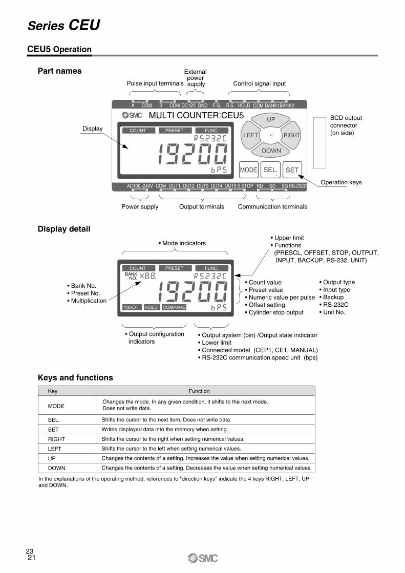
CEU5 Operation
Part names
Display detail
Keys and functions
MULTI COUNTER:CEU5 A COM COM COMB DC12V GND F.G. R.S. HOLD BANK1BANK2
COM S.STOPOUT1 OUT2 OUT3 OUT4 OUT5AC100~240V
COUNT PRESET FUNC.
COUNT PRESET FUNC.BANK
NO.
1SHOT HOLD COMPARE
SD SGRD RS-232C
UP
LEFT RIGHT
DOWN
SEL. SETMODE
Display
Operation keys
BCD outputconnector(on side)
Pulse input terminals
• Mode indicators
Power supply Output terminals Communication terminals
• Output configuration indicators
• Output system (bin) /Output state indicator• Lower limit• Connected model (CEP1, CE1, MANUAL) • RS-232C communication speed unit (bps)
• Count value• Preset value• Numeric value per pulse• Offset setting• Cylinder stop output
• Output type• Input type• Backup• RS-232C• Unit No.
• Upper limit• Functions (PRESCL, OFFSET, STOP, OUTPUT, INPUT, BACKUP, RS-232, UNIT)
• Bank No.• Preset No.• Multiplication
Control signal input
External power supply
Key
MODE
SEL.
SET
RIGHT
LEFT
UP
DOWN
Function
Changes the mode. In any given condition, it shifts to the next mode. Does not write data.
Shifts the cursor to the next item. Does not write data.
Writes displayed data into the memory when setting.
Shifts the cursor to the right when setting numerical values.
Shifts the cursor to the left when setting numerical values.
Changes the contents of a setting. Increases the value when setting numerical values.
Changes the contents of a setting. Decreases the value when setting numerical values.
In the explanations of the operating method, references to "direction keys" indicate the 4 keys RIGHT, LEFT, UP and DOWN.
Series CEU
21
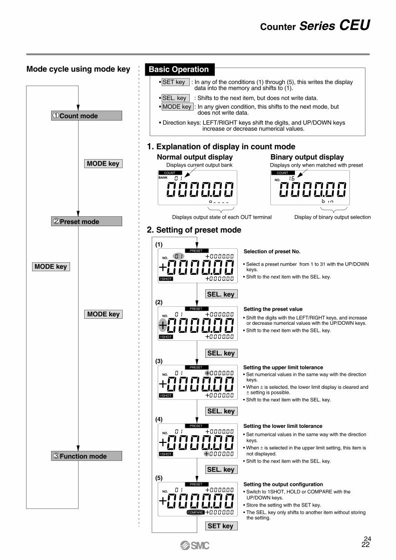
1. Explanation of display in count mode
2. Setting of preset mode
Selection of preset No.
Setting the preset value
Setting the upper limit tolerance
Setting the lower limit tolerance
Setting the output configuration
Normal output display Binary output display
Mode cycle using mode key
MODE key
MODE key
MODE key
SEL. key
SEL. key
SEL. key
SEL. key
SET key
• SET key : In any of the conditions (1) through (5), this writes the display data into the memory and shifts to (1).
• SEL. key : Shifts to the next item, but does not write data.• MODE key : In any given condition, this shifts to the next mode, but does not write data.
• Direction keys: LEFT/RIGHT keys shift the digits, and UP/DOWN keys increase or decrease numerical values.
Basic Operation
COUNT
BANK
1SHOT
NO.
PRESET
Displays current output bank
Displays output state of each OUT terminal
COUNT
NO.
Displays only when matched with preset
Display of binary output selection
NO.
PRESET
1SHOT
NO.
PRESET
1SHOT
NO.
PRESET
1SHOT
NO.
PRESET
(1)
(2)
(3)
(4)
(5)
COMPARE
1 Count mode
2 Preset mode
3 Function mode
• Select a preset number from 1 to 31 with the UP/DOWN keys.
• Shift to the next item with the SEL. key.
• Shift the digits with the LEFT/RIGHT keys, and increase or decrease numerical values with the UP/DOWN keys.
• Shift to the next item with the SEL. key.
• Set numerical values in the same way with the direction keys.
• When ± is selected, the lower limit display is cleared and ± setting is possible.
• Shift to the next item with the SEL. key.
• Set numerical values in the same way with the direction keys.
• When ± is selected in the upper limit setting, this item is not displayed.
• Shift to the next item with the SEL. key.
• Switch to 1SHOT, HOLD or COMPARE with the UP/DOWN keys.
• Store the setting with the SET key.
• The SEL. key only shifts to another item without storing the setting.
24
Counter Series CEU
22
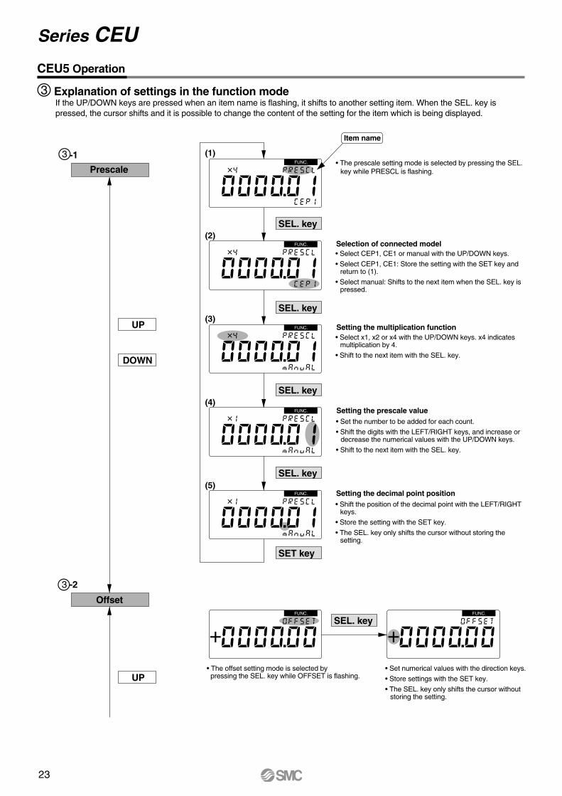
Selection of connected model
Setting the multiplication function
Setting the prescale value
Setting the decimal point position
• The offset setting mode is selected by pressing the SEL. key while OFFSET is flashing.
• Set numerical values with the direction keys.
• Store settings with the SET key.
• The SEL. key only shifts the cursor without storing the setting.
Offset
Prescale
UP
UP
DOWN
SEL. key
SEL. key
SEL. key
SEL. key
SET key
SEL. key
FUNC.
FUNC.
CEU5 Operation
3 -1
3 -2
FUNC.
FUNC.
FUNC.
FUNC.
FUNC.
(1)
(2)
(3)
(4)
(5)
Item name
3 Explanation of settings in the function modeIf the UP/DOWN keys are pressed when an item name is flashing, it shifts to another setting item. When the SEL. key is pressed, the cursor shifts and it is possible to change the content of the setting for the item which is being displayed.
• The prescale setting mode is selected by pressing the SEL. key while PRESCL is flashing.
• Select CEP1, CE1 or manual with the UP/DOWN keys.
• Select CEP1, CE1: Store the setting with the SET key and return to (1).
• Select manual: Shifts to the next item when the SEL. key is pressed.
• Select x1, x2 or x4 with the UP/DOWN keys. x4 indicates multiplication by 4.
• Shift to the next item with the SEL. key.
• Set the number to be added for each count.
• Shift the digits with the LEFT/RIGHT keys, and increase or decrease the numerical values with the UP/DOWN keys.
• Shift to the next item with the SEL. key.
• Shift the position of the decimal point with the LEFT/RIGHT keys.
• Store the setting with the SET key.
• The SEL. key only shifts the cursor without storing the setting.
Series CEU
23
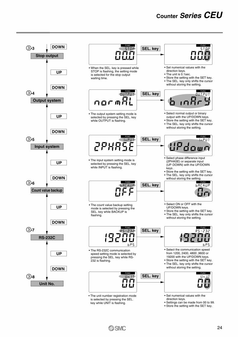
RS-232C
Unit No.
Stop output
UP
DOWN
UP
DOWN
DOWN
UP
DOWN
UP
DOWN
UP
DOWN
SEL. keyFUNC.
Output system
Count value backup
FUNC.
SEL. keyFUNC. FUNC.
SEL. keyFUNC. FUNC.
SEL. keyFUNC. FUNC.
SEL. keyFUNC. FUNC.
SEL. keyFUNC. FUNC.
Input system
• Set numerical values with the direction keys.
• The unit is 0.1sec.• Store the setting with the SET key.• The SEL. key only shifts the cursor
without storing the setting.
• Select normal output or binary output with the UP/DOWN keys.
• Store the setting with the SET key.• The SEL. key only shifts the cursor
without storing the setting.
• Select phase difference input (2PHASE) or separate input (UP·DOWN) with the UP/DOWN keys .
• Store the setting with the SET key.• The SEL. key only shifts the cursor
without storing the setting.
• Select ON or OFF with the UP/DOWN keys.
• Store the setting with the SET key.• The SEL. key only shifts the cursor
without storing the setting.
• Select the communication speed from 1200, 2400, 4800 ,9600 or 19200 with the UP/DOWN keys.
• Store the setting with the SET key.• The SEL. key only shifts the cursor
without storing the setting.
• Set numerical values with the direction keys.
• Settings can be made from 00 to 99.• Store the setting with the SET key.
3 -3
3 -4
3 -5
3 -6
3 -7
3 -8
• When the SEL. key is pressed while STOP is flashing, the setting mode is selected for the stop output waiting time.
• The output system setting mode is selected by pressing the SEL. key while OUTPUT is flashing.
• The input system setting mode is selected by pressing the SEL. key while INPUT is flashing.
• The count value backup setting mode is selected by pressing the SEL. key while BACKUP is flashing.
• The RS-232C communication speed setting mode is selected by pressing the SEL. key while RS-232 is flashing.
• The unit number registration mode is selected by pressing the SEL. key while UNIT is flashing.
Counter Series CEU
24
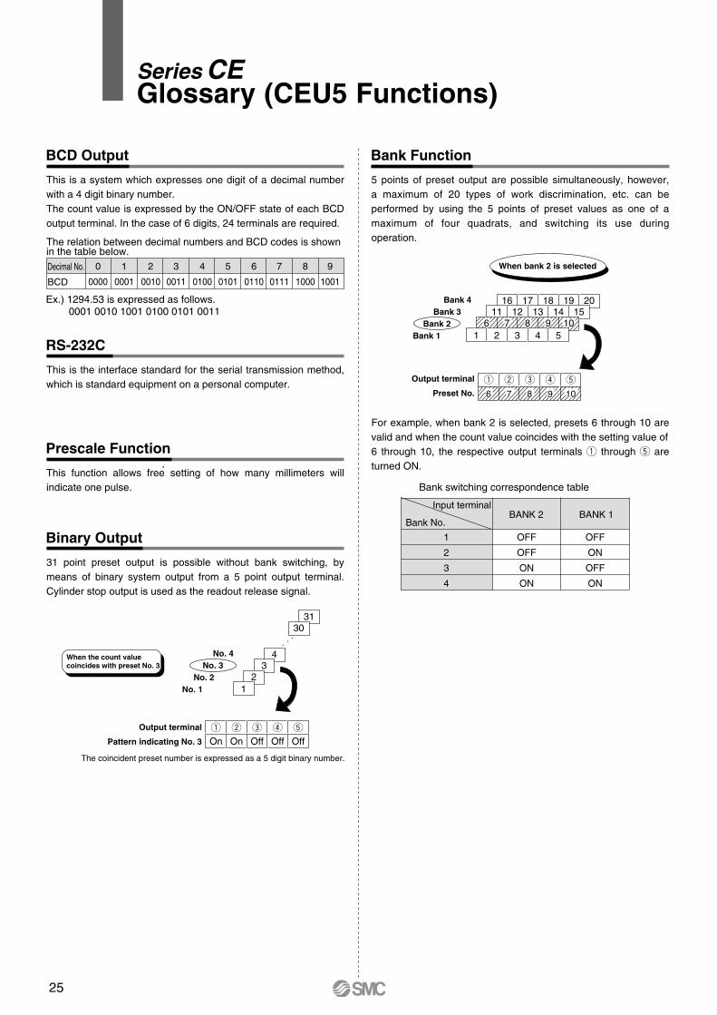
BCD Output
This is a system which expresses one digit of a decimal number with a 4 digit binary number.The count value is expressed by the ON/OFF state of each BCD output terminal. In the case of 6 digits, 24 terminals are required.
Prescale Function
This function allows free setting of how many millimeters will indicate one pulse.
RS-232C
This is the interface standard for the serial transmission method, which is standard equipment on a personal computer.
Bank Function
5 points of preset output are possible simultaneously, however, a maximum of 20 types of work discrimination, etc. can be performed by using the 5 points of preset values as one of a maximum of four quadrats, and switching its use during operation.
For example, when bank 2 is selected, presets 6 through 10 are valid and when the count value coincides with the setting value of 6 through 10, the respective output terminals q through t are turned ON.
Bank 1
Output terminal
Preset No.
Bank 2Bank 3
Bank 4
When bank 2 is selected
Binary Output
31 point preset output is possible without bank switching, by means of binary system output from a 5 point output terminal. Cylinder stop output is used as the readout release signal.
q w e r t
On On Off Off Off
Output terminal
Pattern indicating No. 3
The coincident preset number is expressed as a 5 digit binary number.
No. 1No. 2
No. 3No. 4
3130
43
21
When the count valuecoincides with preset No. 3
The relation between decimal numbers and BCD codes is shownin the table below.
Ex.) 1294.53 is expressed as follows. 0001 0010 1001 0100 0101 0011
Decimal No.
BCD
0
0000
1
0001
2
0010
3
0011
4
0100
5
0101
6
0110
7
0111
8
1000
9
1001
Bank switching correspondence table
Bank No.
1
2
3
4
OFF
OFF
ON
ON
OFF
ON
OFF
ON
Input terminalBANK 2 BANK 1
16 17 18 19 2011 12 13 14 15
6 7 8 9 10
6 7 8 9 10
1 2 3 4 5
q w e r t
Series CEGlossary (CEU5 Functions)
25
Display Offset Function
Normally the count value returns to "0" after resetting, but with this function, the initial value can be set to any desired value.
Hold Function
When "hold" is input, the counter holds the current count value in memory. Next, when the count value is read into a PLC which uses serial or BCD output, etc., the count value that was held can be read in, even if there is a time lag.
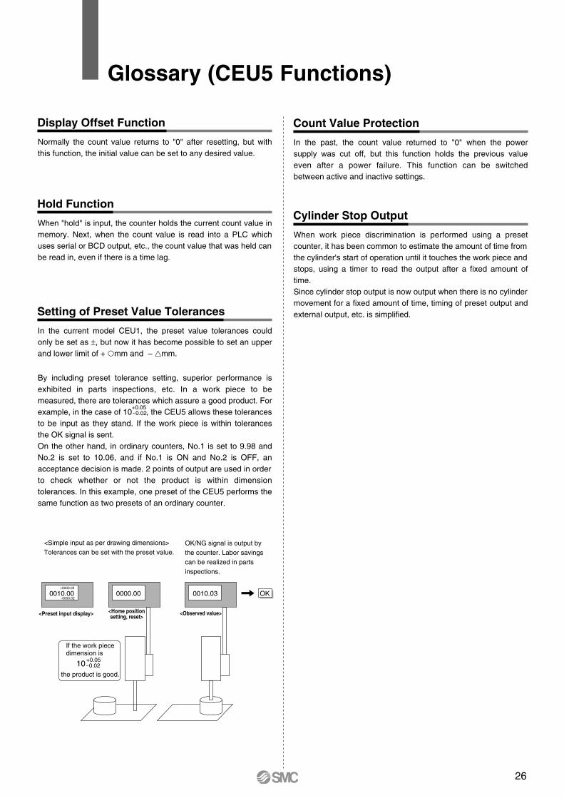
Setting of Preset Value Tolerances
Count Value Protection
In the current model CEU1, the preset value tolerances could only be set as ±, but now it has become possible to set an upper and lower limit of + mm and – mm.
By including preset tolerance setting, superior performance is exhibited in parts inspections, etc. In a work piece to be measured, there are tolerances which assure a good product. For example, in the case of 10 , the CEU5 allows these tolerances to be input as they stand. If the work piece is within tolerances the OK signal is sent.On the other hand, in ordinary counters, No.1 is set to 9.98 and No.2 is set to 10.06, and if No.1 is ON and No.2 is OFF, an acceptance decision is made. 2 points of output are used in order to check whether or not the product is within dimension tolerances. In this example, one preset of the CEU5 performs the same function as two presets of an ordinary counter.
In the past, the count value returned to "0" when the power supply was cut off, but this function holds the previous value even after a power failure. This function can be switched between active and inactive settings.
Cylinder Stop Output
When work piece discrimination is performed using a preset counter, it has been common to estimate the amount of time from the cylinder's start of operation until it touches the work piece and stops, using a timer to read the output after a fixed amount of time.Since cylinder stop output is now output when there is no cylinder movement for a fixed amount of time, timing of preset output and external output, etc. is simplified.
+0.05 – 0.02
0000.000010.00+0000.05
–0000.020010.03
<Simple input as per drawing dimensions>Tolerances can be set with the preset value.
OK
<Observed value><Home positionsetting, reset><Preset input display>
If the work piece dimension is
+0.05– 0.0210
the product is good.
OK/NG signal is output by the counter. Labor savings can be realized in parts inspections.
Glossary (CEU5 Functions)
26
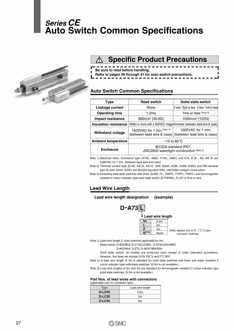
Auto Switch Common Specifications
Lead Wire Length
Type
Leakage current
Operating time
Impact resistance
Insulation resistance
Withstand voltage
Ambient temperature
Enclosure
Reed switch
None
1.2ms
300m/s² 30.6G
1500VAC for 1 min.Note 1)
(between lead wire & case)
Solid state switch
3 wire: 10µA or less 2 wire: 1mA or less
1ms or less Note 3)
1000m/s² 102G
1000VAC for 1 min.(between lead wire & case)
50MΩ or more with a 500VDC megaohmmeter (between lead wire & case)
–10 to 60°CIEC529 standard IP67,
JISC0920 watertight construction Note 2)
Note 1) Electrical entry: Connector type (A73C, A80C, C73C, C80C) and D-9, 9A , A9, A9V are 1000VAC for 1 min. (between lead wire and case)
Note 2) Terminal conduit type (D-A3, A3A, A3C, G39, G39A, G39C, K39A, K39C) and DIN terminal type (D-A44, A44A, A44C) are IEC529 standard IP63, JISC0920 raintight construction.
Note 3) Excluding solid state switches with timer (D-M5TL, G5NTL, F7NTL, F5NTL) and ferromagnetic resistant 2 colour indicator type solid state switch (D-P5DWL). D-J51 is 5ms or less.
Note 1) Lead wire length Z: Auto switches applicable for 5mReed switch: D-B53/B54, D-C73(C)/C80C, D-A73(C)(H)/A80C D-A53/A54, D-Z73, D-90/97/90A/93A Solid state switch: All models are produced upon receipt of order (standard procedure). However, this does not include D-F9, F9V and F7WV.
Note 2) A lead wire length of 3m is standard for solid state switches with timer and water resistant 2 colour indicator type solid state switches. (0.5m is not available.)
Note 3) Lead wire lengths of 3m and 5m are standard for ferromagnetic resistant 2 colour indicator type solid state switches. (0.5m is not available.)
D-A73 Lead wire length
NilLZNNote)
0.5m3m5mNone
Note) Applies only to D– C type connector switches.
L
Lead wire length designation (example)
Be sure to read before handling.Refer to pages 39 through 41 for auto switch precautions.
Specific Product Precautions
Type
D-LC05D-LC30D-LC50
Lead wire length
0.5m
3m
5m
Part Nos. of lead wires with connectors(applicable only for connector type)
Series CEAuto Switch Common Specifications
27
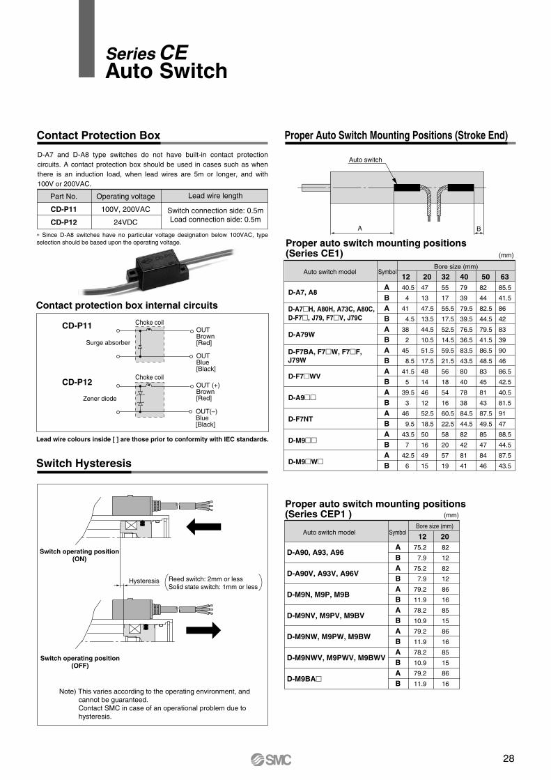
Contact Protection Box
Switch Hysteresis
Proper Auto Switch Mounting Positions (Stroke End)
Proper auto switch mounting positions(Series CE1)
Contact protection box internal circuits
Proper auto switch mounting positions (Series CEP1 )
D-A7 and D-A8 type switches do not have built-in contact protection circuits. A contact protection box should be used in cases such as when there is an induction load, when lead wires are 5m or longer, and with 100V or 200VAC.
∗ Since D-A8 switches have no particular voltage designation below 100VAC, type selection should be based upon the operating voltage.
Switch operating position(ON)
Switch operating position(OFF)
Part No.
CD-P11
CD-P12
Operating voltage
100V, 200VAC
24VDC
Lead wire length
Switch connection side: 0.5mLoad connection side: 0.5m
Auto switch model Symbol
D-A7, A8
D-A7H, A80H, A73C, A80C, D-F7, J79, F7V, J79C
D-A79W
D-F7WV
D-A9
D-F7NT
D-M9
D-M9W
Bore size (mm)
ABABABABABABABABAB
1240.5
4
41
4.5
38
2
45
8.5
41.5
5
39.5
3
46
9.5
43.5
7
42.5
6
2047
13
47.5
13.5
44.5
10.5
51.5
17.5
48
14
46
12
52.5
18.5
50
16
49
15
3255
17
55.5
17.5
52.5
14.5
59.5
21.5
56
18
54
16
60.5
22.5
58
20
57
19
4079
39
79.5
39.5
76.5
36.5
83.5
43.5
80
40
78
38
84.5
44.5
82
42
81
41
5082
44
82.5
44.5
79.5
41.5
86.5
48.5
83
45
81
43
87.5
49.5
85
47
84
46
6385.5
41.5
86
42
83
39
90
46
86.5
42.5
40.5
81.5
91
47
88.5
44.5
87.5
43.5
D-A90, A93, A96
D-A90V, A93V, A96V
D-M9N, M9P, M9B
D-M9NV, M9PV, M9BV
D-M9NW, M9PW, M9BW
D-M9NWV, M9PWV, M9BWV
D-M9BA
Auto switch model Symbol
ABABABABABABAB
Bore size (mm)
1275.2
7.9
75.2
7.9
79.2
11.9
78.2
10.9
79.2
11.9
78.2
10.9
79.2
11.9
2082
12
82
12
86
16
85
15
86
16
85
15
86
16
Hysteresis Reed switch: 2mm or lessSolid state switch: 1mm or less
Note) This varies according to the operating environment, and cannot be guaranteed. Contact SMC in case of an operational problem due to hysteresis.
Surge absorber
Choke coilOUTBrown[Red]
OUTBlue[Black]
OUT (+)Brown[Red]
OUT(–)Blue[Black]
Choke coil
CD-P11
CD-P12
Zener diode
Lead wire colours inside [ ] are those prior to conformity with IEC standards.
A B
D-F7BA, F7W, F7F, J79W
(mm)
(mm)
Auto switch
Series CEAuto Switch
Auto Switch Common Specifications
Lead Wire Length
Type
Leakage current
Operating time
Impact resistance
Insulation resistance
Withstand voltage
Ambient temperature
Enclosure
Reed switch
None
1.2ms
300m/s² 30.6G
1500VAC for 1 min.Note 1)
(between lead wire & case)
Solid state switch
3 wire: 10µA or less 2 wire: 1mA or less
1ms or less Note 3)
1000m/s² 102G
1000VAC for 1 min.(between lead wire & case)
50MΩ or more with a 500VDC megaohmmeter (between lead wire & case)
–10 to 60°CIEC529 standard IP67,
JISC0920 watertight construction Note 2)
Note 1) Electrical entry: Connector type (A73C, A80C, C73C, C80C) and D-9, 9A , A9, A9V are 1000VAC for 1 min. (between lead wire and case)
Note 2) Terminal conduit type (D-A3, A3A, A3C, G39, G39A, G39C, K39A, K39C) and DIN terminal type (D-A44, A44A, A44C) are IEC529 standard IP63, JISC0920 raintight construction.
Note 3) Excluding solid state switches with timer (D-M5TL, G5NTL, F7NTL, F5NTL) and ferromagnetic resistant 2 colour indicator type solid state switch (D-P5DWL). D-J51 is 5ms or less.
Note 1) Lead wire length Z: Auto switches applicable for 5mReed switch: D-B53/B54, D-C73(C)/C80C, D-A73(C)(H)/A80C D-A53/A54, D-Z73, D-90/97/90A/93A Solid state switch: All models are produced upon receipt of order (standard procedure). However, this does not include D-F9, F9V and F7WV.
Note 2) A lead wire length of 3m is standard for solid state switches with timer and water resistant 2 colour indicator type solid state switches. (0.5m is not available.)
Note 3) Lead wire lengths of 3m and 5m are standard for ferromagnetic resistant 2 colour indicator type solid state switches. (0.5m is not available.)
D-A73 Lead wire length
NilLZNNote)
0.5m3m5mNone
Note) Applies only to D– C type connector switches.
L
Lead wire length designation (example)
Be sure to read before handling.Refer to pages 39 through 41 for auto switch precautions.
Specific Product Precautions
Type
D-LC05D-LC30D-LC50
Lead wire length
0.5m
3m
5m
Part Nos. of lead wires with connectors(applicable only for connector type)
28
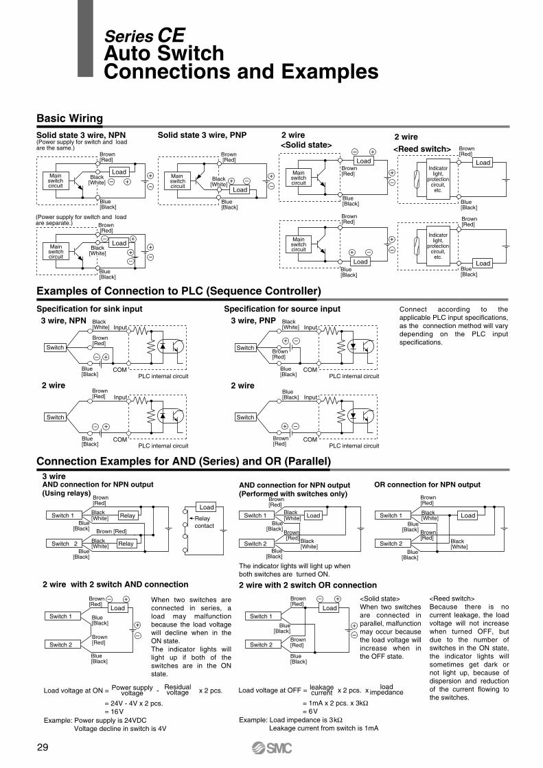
Basic WiringSolid state 3 wire, NPN(Power supply for switch and load are the same.)
Specification for sink input
2 wire
Specification for source input
2 wire with 2 switch AND connection 2 wire with 2 switch OR connection
2 wire 2 wire
Solid state 3 wire, PNP
Example: Power supply is 24VDC Voltage decline in switch is 4V
Example: Load impedance is 3kΩLeakage current from switch is 1mA
(Power supply for switch and load are separate.)
Connection Examples for AND (Series) and OR (Parallel)
Examples of Connection to PLC (Sequence Controller)
Connect according to the applicable PLC input specifications, as the connection method will vary depending on the PLC input specifications.
When two switches are connected in series, a load may malfunction because the load voltage will decline when in the ON state.The indicator lights will light up if both of the switches are in the ON state.
<Solid state>When two switches are connected in parallel, malfunction may occur because the load voltage will increase when in the OFF state.
Blue[Black]
Main switchcircuit
Load
Brown [Red]
Black[White]
Mainswitchcircuit
Brown[Red]
Load
Blue[Black]
Black[White]
Mainswitchcircuit
LoadBlue[Black]
Brown[Red]
Mainswitchcircuit
Load
Blue[Black]
Brown[Red]
Mainswitchcircuit
Load
Brown [Red]
Blue[Black]
Black[White]
PLC internal circuitCOM
Switch
InputBlack[White]
Brown[Red]
Blue[Black]
PLC internal circuitCOM
Switch
InputBrown[Red]
Blue[Black] PLC internal circuit
Switch
Input
COM
Blue[Black]
Brown[Red]
PLC internal circuitCOM
Switch
InputBlack[White]
Brown[Red]
Blue[Black]
Switch 1
Switch 2
Load
Blue[Black]
Brown[Red]
Blue[Black]
Brown[Red]
Switch 1
Switch 2
Load
Brown[Red]
Blue[Black]
Brown[Red]
Blue[Black]
3 wireOR connection for NPN output
Switch 1
Switch 2
LoadSwitch 1
Brown[Red]
Switch 2
Black[White]
Blue[Black]
Relay
RelayBlack[White]
Load
Relaycontact
AND connection for NPN output(Using relays)
Switch 1
Brown[Red]
Switch 2
Load
Brown[Red]
AND connection for NPN output(Performed with switches only)
The indicator lights will light up when both switches are turned ON.
<Reed switch>
2 wire
Indicatorlight,
protectioncircuit,
etc.
Brown[Red]
Blue[Black]
Load
<Reed switch>
Brown[Red]
Blue[Black]
Load
<Solid state>
3 wire, NPN 3 wire, PNP
Brown [Red]
Blue[Black]
Blue[Black]
Black[White]
Black[White]
Blue[Black]
Brown[Red]
Blue[Black]
Black[White]
Blue[Black]
Black[White]
Brown[Red]
Because there is no current leakage, the load voltage will not increase when turned OFF, but due to the number of switches in the ON state, the indicator lights will sometimes get dark or not light up, because of dispersion and reduction of the current flowing to the switches.
Indicatorlight,
protectioncircuit,
etc.
Load voltage at ON = - x 2 pcs.
= 24V - 4V x 2 pcs. = 16V
Power supply voltage
Residual voltage
leakagecurrent
loadimpedanceLoad voltage at OFF = x 2 pcs. x
= 1mA x 2 pcs. x 3kΩ= 6V
Series CEAuto SwitchConnections and Examples
29
Basic WiringSolid state 3 wire, NPN(Power supply for switch and load are the same.)
Specification for sink input
2 wire
Specification for source input
2 wire with 2 switch AND connection 2 wire with 2 switch OR connection
2 wire 2 wire
Solid state 3 wire, PNP
Example: Power supply is 24VDC Voltage decline in switch is 4V
Example: Load impedance is 3kΩLeakage current from switch is 1mA
(Power supply for switch and load are separate.)
Connection Examples for AND (Series) and OR (Parallel)
Examples of Connection to PLC (Sequence Controller)
Connect according to the applicable PLC input specifications, as the connection method will vary depending on the PLC input specifications.
When two switches are connected in series, a load may malfunction because the load voltage will decline when in the ON state.The indicator lights will light up if both of the switches are in the ON state.
<Solid state>When two switches are connected in parallel, malfunction may occur because the load voltage will increase when in the OFF state.
Blue[Black]
Main switchcircuit
Load
Brown [Red]
Black[White]
Mainswitchcircuit
Brown[Red]
Load
Blue[Black]
Black[White]
Mainswitchcircuit
LoadBlue[Black]
Brown[Red]
Mainswitchcircuit
Load
Blue[Black]
Brown[Red]
Mainswitchcircuit
Load
Brown [Red]
Blue[Black]
Black[White]
PLC internal circuitCOM
Switch
InputBlack[White]
Brown[Red]
Blue[Black]
PLC internal circuitCOM
Switch
InputBrown[Red]
Blue[Black] PLC internal circuit
Switch
Input
COM
Blue[Black]
Brown[Red]
PLC internal circuitCOM
Switch
InputBlack[White]
Brown[Red]
Blue[Black]
Switch 1
Switch 2
Load
Blue[Black]
Brown[Red]
Blue[Black]
Brown[Red]
Switch 1
Switch 2
Load
Brown[Red]
Blue[Black]
Brown[Red]
Blue[Black]
3 wireOR connection for NPN output
Switch 1
Switch 2
LoadSwitch 1
Brown[Red]
Switch 2
Black[White]
Blue[Black]
Relay
RelayBlack[White]
Load
Relaycontact
AND connection for NPN output(Using relays)
Switch 1
Brown[Red]
Switch 2
Load
Brown[Red]
AND connection for NPN output(Performed with switches only)
The indicator lights will light up when both switches are turned ON.
<Reed switch>
2 wire
Indicatorlight,
protectioncircuit,
etc.
Brown[Red]
Blue[Black]
Load
<Reed switch>
Brown[Red]
Blue[Black]
Load
<Solid state>
3 wire, NPN 3 wire, PNP
Brown [Red]
Blue[Black]
Blue[Black]
Black[White]
Black[White]
Blue[Black]
Brown[Red]
Blue[Black]
Black[White]
Blue[Black]
Black[White]
Brown[Red]
Because there is no current leakage, the load voltage will not increase when turned OFF, but due to the number of switches in the ON state, the indicator lights will sometimes get dark or not light up, because of dispersion and reduction of the current flowing to the switches.
Indicatorlight,
protectioncircuit,
etc.
Load voltage at ON = - x 2 pcs.
= 24V - 4V x 2 pcs. = 16V
Power supply voltage
Residual voltage
leakagecurrent
loadimpedanceLoad voltage at OFF = x 2 pcs. x
= 1mA x 2 pcs. x 3kΩ= 6V
Series CESafety Instructions
Note 1) ISO 4414: Pneumatic fluid power -- Recommendations for the application of equipment to transmission and control systems.
Note 2) JIS B 8370: Pneumatic system axiom.
Warning
Caution : Operator error could result in injury or equipment damage.
Warning : Operator error could result in serious injury or loss of life.
Danger : In extreme conditions, there is a possible result of serious injury or loss of life.
These safety instructions are intended to prevent a hazardous situation and/or equipment damage. These instructions indicate the level of potential hazard by a label of "Caution", "Warning" or "Danger". To ensure safety, be sure to observe ISO 4414 Note 1), JIS B 8370 Note 2) and other safety practices.
1 The compatibility of pneumatic equipment is the responsibility of the person who designs the pneumatic system or decides its specifications.Since the products specified here are used in various operating conditions, their compatibility for the specific pneumatic system must be based on specifications or after analysis and/or tests to meet your specific requirements.
2 Only trained personnel should operate pneumatically operated machinery and equipment.Compressed air can be dangerous if an operator is unfamiliar with it. Assembly, handling or repair of pneumatic systems should be performed by trained and experienced operators.
3 Do not service machinery/equipment or attempt to remove components until safety is confirmed.
1.Inspection and maintenance of machinery/equipment should only be performed after confirmation of safe locked-out control positions.
2.When equipment is to be removed, confirm the safety process as mentioned above. Cut the supply pressure for this equipment and exhaust all residual compressed air in the system.
3.Before machinery/equipment is restarted, take measures to prevent shooting-out of cylinder piston rod, etc. (Bleed air into the system gradually to create back-pressure.)
4 Contact SMC if the product is to be used in any of the following conditions:1.Conditions and environments beyond the given specifications, or if product is used outdoors.2.Installation on equipment in conjunction with atomic energy, railway, air navigation, vehicles, medical
equipment, food and beverages, recreation equipment, emergency stop circuits, press applications, or safety equipment.
3.An application which has the possibility of having negative effects on people, property, or animals, requiring special safety analysis.
30
Series CEActuator Precautions 1Be sure to read before handling.
Precautions on design Selection
Warning1. There is a possibility of dangerous sud-
den action by air cylinders if sliding parts of machinery are twisted due to external forces, etc.In such cases, human injury may occur; e.g., by catching hands or feet in the machinery, or damage to the machinery itself may occur. Therefore, the machine should be designed to avoid such dangers.
2. A protective cover is recommended to mini-mize the risk of personal injury.If a stationary object and moving parts of a cylinder are in close proximity, personal injury may occur. Design the structure to avoid contact with the human body.
3. Securely tighten all stationary parts and connected parts so that they will not become loose.When a cylinder operates with high frequency or a cylinder is installed where there is a lot of vibration, ensure that all parts remain secure.
4. A deceleration circuit or shock absorber, etc., may be required.When a driven object is operated at high speed or the load is heavy, a cylinder’s cushion will not be sufficient to absorb the impact. Install a deceleration circuit to reduce the speed before cushioning, or install an external shock absorber to relieve the impact. In this case, the rigidity of the machinery should also be examined.
5. Consider a possible drop in operating pres-sure due to a power outage, etc.When a cylinder is used in a clamping mechanism, there is a danger of work dropping if there is a decrease in clamping force due to a drop in circuit pressure caused by a power outage, etc. Therefore, safety equipment should be installed to prevent dam-age to machinery and human injury. Suspension mechanisms and lifting devices also require consideration for drop prevention.
6. Consider a possible loss of power source.Measures should be taken to protect against human injury and equipment damage in the event that there is a loss of power to equipment controlled by air pressure, electricity or hydraulics, etc.
7. Design circuitry to prevent sudden lurching of driven objects.When a cylinder is driven by an exhaust center type direc-tional control valve or when starting up after residual pressure is exhausted from the circuit, etc., the piston and its driven object will lurch at high speed if pressure is applied to one side of the cyl-inder because of the absence of air pressure inside the cylinder. Therefore, equipment should be selected and circuits designed to prevent sudden lurching, because there is a danger of human injury and/or damage to equipment when this occurs.
8. Consider emergency stops.Design so that human injury and/or damage to machinery and equipment will not be caused when machinery is stopped by a safety device under abnormal conditions, a power outage or a manual emergency stop.
9. Consider the action when operation is restarted after an emergency stop or abnor-mal stop.Design the machinery so that human injury or equipment damage will not occur upon restart of operation. When the cylinder has to be reset at the starting position, install manual safety equipment.
1. Check the specifications.The products advertised in this catalogue are designed according to use in industrial compressed air systems. If the products are used in conditions where pressure, temperature, etc., are out of specification, damage and/or malfunction may be caused. Do not use in these conditions.
Consult SMC if you use a fluid other than compressed air.
2. Intermediate stops.When intermediate stopping of a cylinder piston is performed with a 3 position closed center type directional control valve, it is dif-ficult to achieve stopping positions as accurate and minute as with hydraulic pressure, due to the compressibility of air.
Furthermore, since valves and cylinders, etc. are not guaranteed for zero air leakage, it may not be possible to hold a stopped position for an extended period of time. Contact SMC in case it is necessary to hold a stopped position for an extended period.
1. Use a speed controller to adjust the cylinder drive speed, gradually increasing from a low speed to the desired speed setting.
1. Do not apply strong impact or large moment, etc. when mounting a work piece.An external force greater than the allowable moment can cause rattling in the guide unit and increased sliding resistance, etc.
2. Do not use in applications subject to the effect of a large external force or impact force, etc.This can cause failure.
3. Do not use until you verify that the equip-ment can operate properly.After mounting, repair or modification, etc., connect the air supply and electric power, and then confirm proper mounting by means of appropriate function and leak inspections.
4. Instruction manual.The product should be mounted and operated after thoroughly reading the manual and understanding its contents.
Keep the instruction manual where it can be referred to as needed.
Warning
Caution
Caution
Piping
1. Preparation before piping.Before piping is connected, it should be thoroughly blown out with air (flushing) or washed to remove cutting chips, cutting oil and other debris from inside the pipe.
Caution
Mounting
31
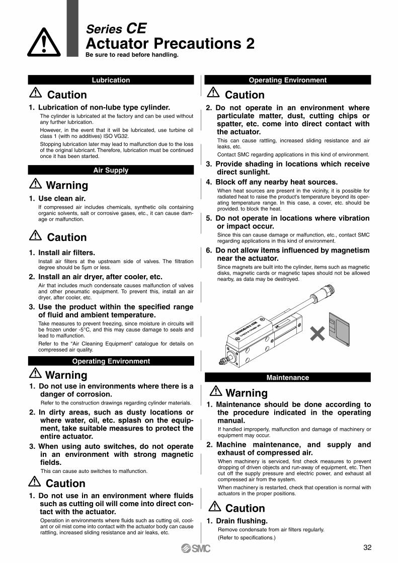
Series CEActuator Precautions 2Be sure to read before handling.
Caution1. Do not use in an environment where fluids
such as cutting oil will come into direct con-tact with the actuator.Operation in environments where fluids such as cutting oil, cool-ant or oil mist come into contact with the actuator body can cause rattling, increased sliding resistance and air leaks, etc.
Lubrication
Air Supply
1. Lubrication of non-lube type cylinder.The cylinder is lubricated at the factory and can be used without any further lubrication.
However, in the event that it will be lubricated, use turbine oil class 1 (with no additives) ISO VG32.
Stopping lubrication later may lead to malfunction due to the loss of the original lubricant. Therefore, lubrication must be continued once it has been started.
Caution
1. Use clean air.If compressed air includes chemicals, synthetic oils containing organic solvents, salt or corrosive gases, etc., it can cause dam-age or malfunction.
1. Install air filters.Install air filters at the upstream side of valves. The filtration degree should be 5µm or less.
2. Install an air dryer, after cooler, etc.Air that includes much condensate causes malfunction of valves and other pneumatic equipment. To prevent this, install an air dryer, after cooler, etc.
3. Use the product within the specified range of fluid and ambient temperature.Take measures to prevent freezing, since moisture in circuits will be frozen under -5°C, and this may cause damage to seals and lead to malfunction.
Refer to the “Air Cleaning Equipment” catalogue for details on compressed air quality.
Warning
Caution
1. Do not use in environments where there is a danger of corrosion.Refer to the construction drawings regarding cylinder materials.
2. In dirty areas, such as dusty locations or where water, oil, etc. splash on the equip-ment, take suitable measures to protect the entire actuator.
3. When using auto switches, do not operate in an environment with strong magnetic fields.This can cause auto switches to malfunction.
Operating Environment
Warning
Operating Environment
Maintenance
Warning1. Maintenance should be done according to
the procedure indicated in the operating manual.If handled improperly, malfunction and damage of machinery or equipment may occur.
2. Machine maintenance, and supply and exhaust of compressed air.When machinery is serviced, first check measures to prevent dropping of driven objects and run-away of equipment, etc. Then cut off the supply pressure and electric power, and exhaust all compressed air from the system.
When machinery is restarted, check that operation is normal with actuators in the proper positions.
1. Drain flushing.Remove condensate from air filters regularly.
(Refer to specifications.)
Caution
2. Do not operate in an environment where particulate matter, dust, cutting chips or spatter, etc. come into direct contact with the actuator.This can cause rattling, increased sliding resistance and air leaks, etc.
Contact SMC regarding applications in this kind of environment.
3. Provide shading in locations which receive direct sunlight.
4. Block off any nearby heat sources.When heat sources are present in the vicinity, it is possible for radiated heat to raise the product's temperature beyond its oper-ating temperature range. In this case, a cover, etc. should be provided. to block the heat.
5. Do not operate in locations where vibration or impact occur.Since this can cause damage or malfunction, etc., contact SMC regarding applications in this kind of environment.
6. Do not allow items influenced by magnetism near the actuator.Since magnets are built into the cylinder, items such as magnetic disks, magnetic cards or magnetic tapes should not be allowed nearby, as data may be destroyed.
Caution
32
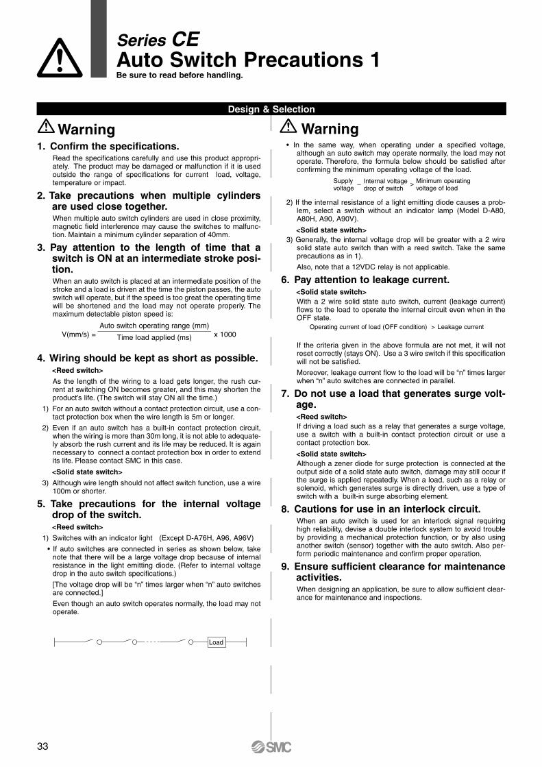
Series CEAuto Switch Precautions 1Be sure to read before handling.
1. Confirm the specifications.Read the specifications carefully and use this product appropri-ately. The product may be damaged or malfunction if it is used outside the range of specifications for current load, voltage, temperature or impact.
2. Take precautions when multiple cylinders are used close together.When multiple auto switch cylinders are used in close proximity, magnetic field interference may cause the switches to malfunc-tion. Maintain a minimum cylinder separation of 40mm.
3. Pay attention to the length of time that a switch is ON at an intermediate stroke posi-tion.When an auto switch is placed at an intermediate position of the stroke and a load is driven at the time the piston passes, the auto switch will operate, but if the speed is too great the operating time will be shortened and the load may not operate properly. The maximum detectable piston speed is:
V(mm/s) = x 1000
4. Wiring should be kept as short as possible.<Reed switch>
As the length of the wiring to a load gets longer, the rush cur-rent at switching ON becomes greater, and this may shorten the product’s life. (The switch will stay ON all the time.)
1) For an auto switch without a contact protection circuit, use a con-tact protection box when the wire length is 5m or longer.
2) Even if an auto switch has a built-in contact protection circuit, when the wiring is more than 30m long, it is not able to adequate-ly absorb the rush current and its life may be reduced. It is again necessary to connect a contact protection box in order to extend its life. Please contact SMC in this case.
<Solid state switch>
3) Although wire length should not affect switch function, use a wire 100m or shorter.
5. Take precautions for the internal voltage drop of the switch.<Reed switch>
1) Switches with an indicator light (Except D-A76H, A96, A96V)
• If auto switches are connected in series as shown below, take note that there will be a large voltage drop because of internal resistance in the light emitting diode. (Refer to internal voltage drop in the auto switch specifications.)
[The voltage drop will be “n” times larger when “n” auto switches are connected.]
Even though an auto switch operates normally, the load may not operate.
Design & Selection
WarningWarning
Auto switch operating range (mm)____________________________Time load applied (ms)
• In the same way, when operating under a specified voltage, although an auto switch may operate normally, the load may not operate. Therefore, the formula below should be satisfied after confirming the minimum operating voltage of the load.
2) If the internal resistance of a light emitting diode causes a prob-lem, select a switch without an indicator lamp (Model D-A80, A80H, A90, A90V).
<Solid state switch>3) Generally, the internal voltage drop will be greater with a 2 wire
solid state auto switch than with a reed switch. Take the same precautions as in 1).
Also, note that a 12VDC relay is not applicable.
6. Pay attention to leakage current.<Solid state switch>With a 2 wire solid state auto switch, current (leakage current) flows to the load to operate the internal circuit even when in the OFF state.
If the criteria given in the above formula are not met, it will not reset correctly (stays ON). Use a 3 wire switch if this specification will not be satisfied.
Moreover, leakage current flow to the load will be “n” times larger when “n” auto switches are connected in parallel.
7. Do not use a load that generates surge volt-age.<Reed switch>If driving a load such as a relay that generates a surge voltage, use a switch with a built-in contact protection circuit or use a contact protection box.
<Solid state switch>Although a zener diode for surge protection is connected at the output side of a solid state auto switch, damage may still occur if the surge is applied repeatedly. When a load, such as a relay or solenoid, which generates surge is directly driven, use a type of switch with a built-in surge absorbing element.
8. Cautions for use in an interlock circuit.When an auto switch is used for an interlock signal requiring high reliability, devise a double interlock system to avoid trouble by providing a mechanical protection function, or by also using another switch (sensor) together with the auto switch. Also per-form periodic maintenance and confirm proper operation.
9. Ensure sufficient clearance for maintenance activities.When designing an application, be sure to allow sufficient clear-ance for maintenance and inspections.
Load
Supplyvoltage
Internal voltagedrop of switch
Minimum operatingvoltage of load
– >
Operating current of load (OFF condition) > Leakage current
33
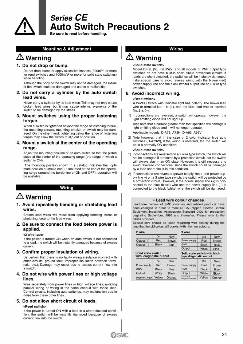
Series CEAuto Switch Precautions 2Be sure to read before handling.
<Solid state switch>Model D-F9(V), F9W(V) and all models of PNP output type switches do not have built-in short circuit prevention circuits. If loads are short circuited, the switches will be instantly damaged.Take special care to avoid reverse wiring with the brown (red) power supply line and the black (white) output line on 3 wire type switches.
6. Avoid incorrect wiring.<Reed switch>A 24VDC switch with indicator light has polarity. The brown lead wire or terminal No. 1 is (+), and the blue lead wire or terminal No. 2 is (–).
1) If connections are reversed, a switch will operate, however, the light emitting diode will not light up.
Also note that a current greater than that specified will damage a light emitting diode and it will no longer operate.
Applicable models: D-A73, A73H, D-A93, A93V
2) Note however, that in the case of 2 color indicator type auto switches (D-A79W), if the wiring is reversed, the the switch will be in a normally ON condition.
<Solid state switch>1) If connections are reversed on a 2 wire type switch, the switch will
not be damaged if protected by a protection circuit, but the switch will always stay in an ON state. However, it is still necessary to avoid reversed connections, since the switch could be damaged by a load short circuit in this condition.
2) If connections are reversed (power supply line + and power sup-ply line –) on a 3 wire type switch, the switch will be protected by a protection circuit. However, if the power supply line (+) is con-nected to the blue (black) wire and the power supply line (–) is connected to the black (white) wire, the switch will be damaged.
1. Do not drop or bump.Do not drop, bump or apply excessive impacts (300m/s² or more for reed switches and 1000m/s² or more for solid state switches) while handling.
Although the body of the switch may not be damaged, the inside of the switch could be damaged and cause a malfunction.
2. Do not carry a cylinder by the auto switch lead wires.Never carry a cylinder by its lead wires. This may not only cause broken lead wires, but it may cause internal elements of the switch to be damaged by the stress.
3. Mount switches using the proper fastening torque.When a switch is tightened beyond the range of fastening torque, the mounting screws, mounting bracket or switch may be dam-aged. On the other hand, tightening below the range of fastening torque may allow the switch to slip out of position.
4. Mount a switch at the center of the operating range.Adjust the mounting position of an auto switch so that the piston stops at the center of the operating range (the range in which a switch is ON).
(The mounting position shown in a catalog indicates the opti-mum position at stroke end.) If mounted at the end of the operat-ing range (around the borderline of ON and OFF), operation will be unstable.
Mounting & Adjustment Wiring
Wiring
Warning
1. Avoid repeatedly bending or stretching lead wires.Broken lead wires will result from applying bending stress or stretching force to the lead wires.
2. Be sure to connect the load before power is applied.<2 wire type>If the power is turned ON when an auto switch is not connected to a load, the switch will be instantly damaged because of excess current.
3. Confirm proper insulation of wiring.Be certain that there is no faulty wiring insulation (contact with other circuits, ground fault, improper insulation between termi-nals, etc.). Damage may occur due to excess current flow into a switch.
4. Do not wire with power lines or high voltage lines.Wire separately from power lines or high voltage lines, avoiding parallel wiring or wiring in the same conduit with these lines. Control circuits, including auto switches, may malfunction due to noise from these other lines.
5. Do not allow short circuit of loads.<Reed switch>If the power is turned ON with a load in a short-circuited condi-tion, the switch will be instantly damaged because of excess current flow into the switch.
Warning ∗ Lead wire colour changes
Old
RedBlack
NewBrownBlue
Output (+)Output (–)
2 wireOld
RedBlackWhite
NewBrownBlueBlack
Power supply
GND
Output
3 wire
Old
RedBlackWhiteYellow
NewBrownBlueBlack
Orange
Power supply
GND
OutputDiagnostic Output
Solid state switchwith diagnostic output
Old
RedBlackWhiteYellow
NewBrownBlueBlack
Orange
Power supply
GND
OutputLatch typediagnostic Output
Solid state switch with latchtype diagnostic output
Lead wire colours of SMC switches and related products have been changed in order to meet NECA (Nippon Electric Control Equipment Industries Association) Standard 0402 for production beginning September, 1996 and thereafter. Please refer to the tables provided.Special care should be taken regarding wire polarity during the time that the old colors still coexist with the new colours.
Warning
34
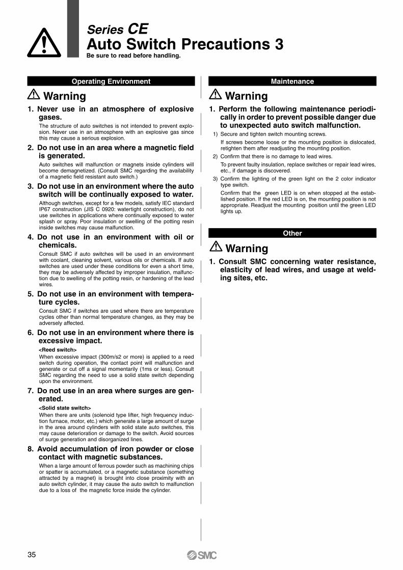
Series CEAuto Switch Precautions 3Be sure to read before handling.
1. Never use in an atmosphere of explosive gases. The structure of auto switches is not intended to prevent explo-sion. Never use in an atmosphere with an explosive gas since this may cause a serious explosion.
2. Do not use in an area where a magnetic field is generated.Auto switches will malfunction or magnets inside cylinders will become demagnetized. (Consult SMC regarding the availability of a magnetic field resistant auto switch.)
3. Do not use in an environment where the auto switch will be continually exposed to water.Although switches, except for a few models, satisfy IEC standard IP67 construction (JIS C 0920: watertight construction), do not use switches in applications where continually exposed to water splash or spray. Poor insulation or swelling of the potting resin inside switches may cause malfunction.
4. Do not use in an environment with oil or chemicals.Consult SMC if auto switches will be used in an environment with coolant, cleaning solvent, various oils or chemicals. If auto switches are used under these conditions for even a short time, they may be adversely affected by improper insulation, malfunc-tion due to swelling of the potting resin, or hardening of the lead wires.
5. Do not use in an environment with tempera-ture cycles.Consult SMC if switches are used where there are temperature cycles other than normal temperature changes, as they may be adversely affected.
6. Do not use in an environment where there is excessive impact.<Reed switch>When excessive impact (300m/s2 or more) is applied to a reed switch during operation, the contact point will malfunction and generate or cut off a signal momentarily (1ms or less). Consult SMC regarding the need to use a solid state switch depending upon the environment.
7. Do not use in an area where surges are gen-erated.<Solid state switch>When there are units (solenoid type lifter, high frequency induc-tion furnace, motor, etc.) which generate a large amount of surge in the area around cylinders with solid state auto switches, this may cause deterioration or damage to the switch. Avoid sources of surge generation and disorganized lines.
8. Avoid accumulation of iron powder or close contact with magnetic substances.When a large amount of ferrous powder such as machining chips or spatter is accumulated, or a magnetic substance (something attracted by a magnet) is brought into close proximity with an auto switch cylinder, it may cause the auto switch to malfunction due to a loss of the magnetic force inside the cylinder.
Operating Environment Maintenance
WarningWarning1. Perform the following maintenance periodi-
cally in order to prevent possible danger due to unexpected auto switch malfunction.
1) Secure and tighten switch mounting screws.
If screws become loose or the mounting position is dislocated, retighten them after readjusting the mounting position.
2) Confirm that there is no damage to lead wires.
To prevent faulty insulation, replace switches or repair lead wires, etc., if damage is discovered.
3) Confirm the lighting of the green light on the 2 color indicator type switch.
Confirm that the green LED is on when stopped at the estab-lished position. If the red LED is on, the mounting position is not appropriate. Readjust the mounting position until the green LED lights up.
Other
Warning1. Consult SMC concerning water resistance,
elasticity of lead wires, and usage at weld-ing sites, etc.
35
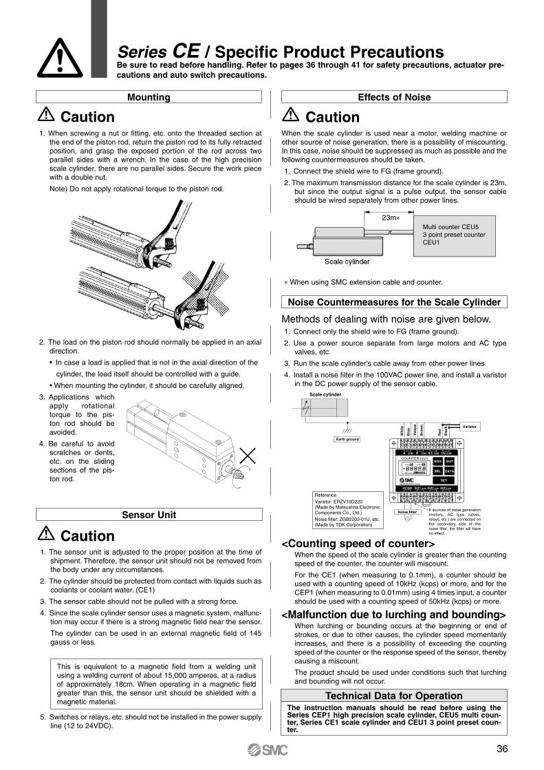
Noise Countermeasures for the Scale Cylinder
Methods of dealing with noise are given below.1. Connect only the shield wire to FG (frame ground).
2. Use a power source separate from large motors and AC type valves, etc.
3. Run the scale cylinder's cable away from other power lines.
4. Install a noise filter in the 100VAC power line, and install a varistor in the DC power supply of the sensor cable.
Series CE / Specific Product PrecautionsBe sure to read before handling. Refer to pages 36 through 41 for safety precautions, actuator pre-cautions and auto switch precautions.
Wh
ite
Blu
e
Yel
low
Bro
wn
Red
Bla
ck
Varistor
Noise filter
Earth ground
ReferenceVaristor: ERZV10D220(Made by Matsushita Electronic Components Co., Ltd.)Noise filter: ZGB2203-01U, etc.(Made by TDK Corporation)
If sources of noise generation (motors, AC type valves, relays, etc.) are connected on the secondary side of the noise filter, the filter will have no effect.
Scale cylinder
COM COM COM COM12V
AC100V OUT1 COM OUT2 COM COMOUT3
MODE SHIFT
SEL. DATA
SET
R.S.BA
COUNTER:CEU1
PRG STEP
SET 1 2
MONOSASHI-KUN
OUT 1 2 3
<Counting speed of counter>When the speed of the scale cylinder is greater than the counting speed of the counter, the counter will miscount.
For the CE1 (when measuring to 0.1mm), a counter should be used with a counting speed of 10kHz (kcps) or more, and for the CEP1 (when measuring to 0.01mm) using 4 times input, a counter should be used with a counting speed of 50kHz (kcps) or more.
<Malfunction due to lurching and bounding>When lurching or bounding occurs at the beginning or end of strokes, or due to other causes, the cylinder speed momentarily increases, and there is a possibility of exceeding the counting speed of the counter or the response speed of the sensor, thereby causing a miscount.
The product should be used under conditions such that lurching and bounding will not occur.
Technical Data for OperationThe instruction manuals should be read before using the Series CEP1 high precision scale cylinder, CEU5 multi coun-ter, Series CE1 scale cylinder and CEU1 3 point preset coun-ter.
CautionMounting
Sensor Unit
1. When screwing a nut or fitting, etc. onto the threaded section at the end of the piston rod, return the piston rod to its fully retracted position, and grasp the exposed portion of the rod across two parallel sides with a wrench. In the case of the high precision scale cylinder, there are no parallel sides. Secure the work piece with a double nut.
Note) Do not apply rotational torque to the piston rod.
1. The sensor unit is adjusted to the proper position at the time of shipment. Therefore, the sensor unit should not be removed from the body under any circumstances.
2. The cylinder should be protected from contact with liquids such as coolants or coolant water. (CE1)
3. The sensor cable should not be pulled with a strong force.
4. Since the scale cylinder sensor uses a magnetic system, malfunc-tion may occur if there is a strong magnetic field near the sensor.
The cylinder can be used in an external magnetic field of 145 gauss or less.
This is equivalent to a magnetic field from a welding unit using a welding current of about 15,000 amperes, at a radius of approximately 18cm. When operating in a magnetic field greater than this, the sensor unit should be shielded with a magnetic material.
5. Switches or relays, etc. should not be installed in the power supply line (12 to 24VDC).
Effects of Noise
When the scale cylinder is used near a motor, welding machine or other source of noise generation, there is a possibility of miscounting. In this case, noise should be suppressed as much as possible and the following countermeasures should be taken.
1. Connect the shield wire to FG (frame ground).
2. The maximum transmission distance for the scale cylinder is 23m, but since the output signal is a pulse output, the sensor cable should be wired separately from other power lines.
∗ When using SMC extension cable and counter.
Caution
Caution
Multi counter CEU5 3 point preset counter CEU1
2. The load on the piston rod should normally be applied in an axial direction.
• In case a load is applied that is not in the axial direction of the
cylinder, the load itself should be controlled with a guide.
• When mounting the cylinder, it should be carefully aligned.
3. Applications which apply rotational torque to the pis-ton rod should be avoided.
4. Be careful to avoid scratches or dents, etc. on the sliding sections of the pis-ton rod.
23m∗
36

SMC CORPORATION Akihabara UDX 15F, 4-14-1, Sotokanda, Chiyoda-ku, Tokyo 101-0021, JAPAN Phone: 03-5207-8249 FAX: 03-5298-5362Specifications are subject to change without prior notice
and any obligation on the part of the manufacturer.
ARGENTINA, AUSTRALIA, BOLIVIA, BRASIL, CANADA, CHILE,CHINA, HONG KONG, INDIA, INDONESIA, MALAYSIA, MEXICO,NEW ZEALAND, PHILIPPINES, SINGAPORE, SOUTH KOREA,
TAIWAN, THAILAND, USA, VENEZUELA
OTHER SUBSIDIARIES WORLDWIDE:
© DiskArt™ 1988
© DiskArt™ UKSMC Pneumatics (UK) LtdVincent Avenue, Crownhill, Milton Keynes, MK8 0ANPhone: +44 (0)800 1382930 Fax: +44 (0)1908-555064E-mail: [email protected]://www.smcpneumatics.co.uk
AustriaSMC Pneumatik GmbH (Austria).Girakstrasse 8, A-2100 KorneuburgPhone: +43 2262-62280, Fax: +43 2262-62285E-mail: [email protected]://www.smc.at
Czech RepublicSMC Industrial Automation CZ s.r.o.Hudcova 78a, CZ-61200 BrnoPhone: +420 5 414 24611, Fax: +420 5 412 18034E-mail: [email protected]://www.smc.cz
PortugalSMC Sucursal Portugal, S.A.Rua de Engº Ferreira Dias 452, 4100-246 PortoPhone: +351 22-610-89-22, Fax: +351 22-610-89-36E-mail: [email protected]://www.smces.es
BelgiumSMC Pneumatics N.V./S.A.Nijverheidsstraat 20, B-2160 WommelgemPhone: +32 (0)3-355-1464, Fax: +32 (0)3-355-1466E-mail: [email protected]://www.smcpneumatics.be
LithuaniaSMC Pneumatics Lietuva, UABOslo g.1, LT-04123 VilniusPhone: +370 5 264 81 26, Fax: +370 5 264 81 26
LatviaSMC Pneumatics Latvia SIASmerla 1-705, Riga LV-1006Phone: +371 781-77-00, Fax: +371 781-77-01E-mail: [email protected]://www.smclv.lv
SwedenSMC Pneumatics Sweden ABEkhagsvägen 29-31, S-141 71 HuddingePhone: +46 (0)8-603 12 00, Fax: +46 (0)8-603 12 90E-mail: [email protected]://www.smc.nu
FranceSMC Pneumatique, S.A.1, Boulevard de Strasbourg, Parc Gustave EiffelBussy Saint Georges F-77607 Marne La Vallee Cedex 3Phone: +33 (0)1-6476 1000, Fax: +33 (0)1-6476 1010E-mail: [email protected]://www.smc-france.fr
FinlandSMC Pneumatics Finland OyPL72, Tiistinniityntie 4, SF-02231 ESPOOPhone: +358 207 513513, Fax: +358 207 513595E-mail: [email protected]://www.smc.fi
EstoniaSMC Pneumatics Estonia OÜLaki 12, 106 21 TallinnPhone: +372 6510370, Fax: +372 65110371E-mail: [email protected]://www.smcpneumatics.ee
GreeceSMC Hellas EPEAnagenniseos 7-9 - P.C. 14342. N. Philadelphia, AthensPhone: +30-210-2717265, Fax: +30-210-2717766E-mail: [email protected]://www.smchellas.gr
TurkeyEntek Pnömatik San. ve Tic. A*.Perpa Ticaret Merkezi B Blok Kat:11 No: 1625, TR-34386, Okmeydani, IstanbulPhone: +90 (0)212-444-0762, Fax: +90 (0)212-221-1519E-mail: [email protected]://www.entek.com.tr
PolandSMC Industrial Automation Polska Sp.z.o.o.ul. Poloneza 89, PL-02-826 Warszawa, Phone: +48 22 211 9600, Fax: +48 22 211 9617E-mail: [email protected]://www.smc.pl
NetherlandsSMC Pneumatics BVDe Ruyterkade 120, NL-1011 AB AmsterdamPhone: +31 (0)20-5318888, Fax: +31 (0)20-5318880E-mail: [email protected]://www.smcpneumatics.nl
IrelandSMC Pneumatics (Ireland) Ltd.2002 Citywest Business Campus, Naas Road, Saggart, Co. DublinPhone: +353 (0)1-403 9000, Fax: +353 (0)1-464-0500E-mail: [email protected]://www.smcpneumatics.ie
HungarySMC Hungary Ipari Automatizálási Kft.Budafoki ut 107-113, H-1117 BudapestPhone: +36 1 371 1343, Fax: +36 1 371 1344E-mail: [email protected]://www.smc.hu
SwitzerlandSMC Pneumatik AGDorfstrasse 7, CH-8484 WeisslingenPhone: +41 (0)52-396-3131, Fax: +41 (0)52-396-3191E-mail: [email protected]://www.smc.ch
ItalySMC Italia S.p.AVia Garibaldi 62, I-20061Carugate, (Milano)Phone: +39 (0)2-92711, Fax: +39 (0)2-9271365E-mail: [email protected]://www.smcitalia.it
GermanySMC Pneumatik GmbHBoschring 13-15, D-63329 EgelsbachPhone: +49 (0)6103-4020, Fax: +49 (0)6103-402139E-mail: [email protected]://www.smc-pneumatik.de
SloveniaSMC industrijska Avtomatika d.o.o.Mirnska cesta 7, SLO-8210 TrebnjePhone: +386 7 3885412 Fax: +386 7 3885435E-mail: [email protected]://www.smc.si
SlovakiaSMC Priemyselná Automatizáciá, s.r.o.Námestie Matina Benku 10, SK-81107 BratislavaPhone: +421 2 444 56725, Fax: +421 2 444 56028E-mail: [email protected]://www.smc.sk
RomaniaSMC Romania srlStr Frunzei 29, Sector 2, BucharestPhone: +40 213205111, Fax: +40 213261489E-mail: [email protected]://www.smcromania.ro
NorwaySMC Pneumatics Norway A/SVollsveien 13 C, Granfos Næringspark N-1366 LysakerTel: +47 67 12 90 20, Fax: +47 67 12 90 21E-mail: [email protected]://www.smc-norge.no
DenmarkSMC Pneumatik A/SKnudsminde 4B, DK-8300 OdderPhone: +45 70252900, Fax: +45 70252901E-mail: [email protected]://www.smcdk.com
RussiaSMC Pneumatik LLC.4B Sverdlovskaja nab, St. Petersburg 195009Phone.:+7 812 718 5445, Fax:+7 812 718 5449E-mail: [email protected]://www.smc-pneumatik.ru
SpainSMC España, S.A.Zuazobidea 14, 01015 VitoriaPhone: +34 945-184 100, Fax: +34 945-184 124E-mail: [email protected]://www.smces.es
http://www.smc.euhttp://www.smcworld.com
EUROPEAN SUBSIDIARIES:
BulgariaSMC Industrial Automation Bulgaria EOOD16 kliment Ohridski Blvd., fl.13 BG-1756 SofiaPhone:+359 2 9744492, Fax:+359 2 9744519E-mail: [email protected]://www.smc.bg
CroatiaSMC Industrijska automatika d.o.o.Crnomerec 12, 10000 ZAGREBPhone: +385 1 377 66 74, Fax: +385 1 377 66 74E-mail: [email protected]://www.smc.hr
1st printing LY printing LY 00 Printed in Spain