Embed Size (px)
Citation preview

EMC ScaleIO™
V1.32
Installation Guide
302-001-995REV 01

EMC ScaleIO Installation Guide2
Copyright © 2015 EMC Corporation. All rights reserved. Published in the USA.
Published May 2015
EMC believes the information in this publication is accurate as of its publication date. The information is subject to change without notice.
The information in this publication is provided as is. EMC Corporation makes no representations or warranties of any kind with respect to the information in this publication, and specifically disclaims implied warranties of merchantability or fitness for a particular purpose. Use, copying, and distribution of any EMC software described in this publication requires an applicable software license.
EMC2, EMC, and the EMC logo are registered trademarks or trademarks of EMC Corporation in the United States and other countries. All other trademarks used herein are the property of their respective owners.
For the most up-to-date regulatory document for your product line, go to EMC Online Support (https://support.emc.com).

CONTENTS
Preface
Part 1 Introduction
Chapter 1 Introduction to EMC ScaleIO
What is ScaleIO?............................................................................ 15 System requirements..................................................................... 16 What’s new in this version? ........................................................... 18 Product limits ................................................................................ 19
Chapter 2 Architecture
System .......................................................................................... 21Hardware................................................................................. 21Software .................................................................................. 22
Storage definitions ........................................................................ 23Protection Domains ................................................................. 23Storage Pools .......................................................................... 24Fault Sets ................................................................................ 26Naming.................................................................................... 27
Protection and load balancing ....................................................... 28Rebuild.................................................................................... 28Rebuild throttling..................................................................... 28Rebalance ............................................................................... 30Rebalance throttling ................................................................ 30
Networking.................................................................................... 31 Implementing ScaleIO ................................................................... 36
Physical layer .......................................................................... 36SAN virtualization layer............................................................ 39
Other functions ............................................................................. 40 Maintenance ................................................................................. 42
Maintaining the physical layer ................................................. 42Maintaining the virtualization layer.......................................... 43
Snapshots..................................................................................... 43Snapshot operations ............................................................... 45
Management tools......................................................................... 45
EMC ScaleIO Installation Guide 3

Contents
Configuring direct attached storage (DAS)...................................... 46 Implementing ScaleIO over a virtual system................................... 47
VMware ................................................................................... 47Xen implementation ................................................................ 48
Part 2 Deploying ScaleIO Systems
Chapter 3 Installing on Physical Servers
Preparing the Installation Manager and the Gateway...................... 52Preparing the IM on a Linux server ........................................... 53Preparing the IM on a Windows server ..................................... 55
Installing with the full Installation Manager.................................... 56Preparing the CSV topology file ................................................ 56Installing with the CLI .............................................................. 61Installing with the web client ................................................... 66
Installing with the Installation Manager wizard .............................. 75Enabling your storage .............................................................. 80
Installing the ScaleIO GUI .............................................................. 81 Configuring the Installation Manager ............................................. 82
Chapter 4 Installing on ESX Servers
Before you begin ........................................................................... 86Deployment prerequisites........................................................ 86Other deployment considerations............................................ 88
Deploying ScaleIO ......................................................................... 89 Installing the ScaleIO GUI ............................................................ 112
Part 3 Reference
Appendix A Manual Installation
Manual installation on physical servers ....................................... 115Installing on Linux servers ..................................................... 117Installing on Windows servers ............................................... 121
Quick installation and provisioning example................................ 124 Deploying ScaleIO on ESX............................................................ 128
4 EMC ScaleIO Installation Guide
Contents
Manually upgrading ScaleIO components .................................... 133Before you begin.................................................................... 133Upgrading Windows systems ................................................. 133Upgrading Linux systems ....................................................... 138Upgrading VMware systems................................................... 142
Appendix B Advanced Topics
Advanced Gateway topics ............................................................ 147Enabling and disabling Gateway components ........................ 147Using a custom Java configuration for the Gateway ................ 148Installing the Gateway without assigning an admin password 149Certificate management for ScaleIO Gateway ......................... 149OpenStack interoperation with the ScaleIO Gateway.............. 153Generating a self-signed certificate using the keytool utility... 154
Advanced Installation Manager topics ......................................... 154Adding devices to SDS nodes on Windows servers................. 155Automated installation of ScaleIO components...................... 156Installing without validating Linux devices............................. 158Installation Manager CLI commands ...................................... 158
Advanced VMware plug-in topics ................................................. 160Manual registration of the ScaleIO plug-in ............................. 162Troubleshooting plug-in registration issues ........................... 164
Appendix C Upgrading and Maintaining
Upgrading from a previous version............................................... 165Upgrading non-VMware servers from v1.3x ............................ 165Upgrading VMware servers from v1.3x ................................... 170
Maintaining a ScaleIO system...................................................... 175Extending an existing ScaleIO system .................................... 175Performing the Get Info operation .......................................... 176Getting the Installation Manager logs..................................... 178Removing components .......................................................... 178
Appendix D Troubleshooting and FAQ
Troubleshooting .......................................................................... 183 Frequently asked questions ......................................................... 186
Glossary
EMC ScaleIO Installation Guide 5

Contents
6 EMC ScaleIO Installation Guide

Title Page
FIGURES
1 ScaleIO architecture ...................................................................................... 232 Protection Domains and Storage Pools .......................................................... 243 Protection Domains, Storage Pools, and Fault Sets ........................................ 264 ScaleIO system deployed on a single network (Windows) .............................. 355 ScaleIO system deployed on separate networks (Windows) ........................... 366 Physical layout example ................................................................................ 387 Snapshot operations ..................................................................................... 448 ScaleIO implementation on ESX..................................................................... 479 ScaleIO Xen virtual machine architecture ....................................................... 4810 CSV—Linux example ...................................................................................... 5711 CSV—Windows example ................................................................................ 58
EMC ScaleIO Installation Guide 7

Figures
8 EMC ScaleIO Installation Guide

PREFACE
As part of an effort to improve its product lines, EMC periodically releases revisions of its software and hardware. Therefore, some functions described in this document might not be supported by all versions of the software or hardware currently in use. The product release notes provide the most up-to-date information on product features.
Contact your EMC technical support professional if a product does not function properly or does not function as described in this document.
Note: This document was accurate at publication time. Go to EMC Online Support (https://support.emc.com) to ensure that you are using the latest version of this document.
PurposeThis document describes the ScaleIO virtual SAN storage system. It describes the architecture, deployment, and use of the system.
AudienceThis document is intended for IT professionals-system and storage administrators-who will be involved in deploying and managing ScaleIO.
Related documentationThe following EMC publication provides additional information:
◆ EMC ScaleIO Release Notes
◆ EMC ScaleIO User Guide
◆ EMC ScaleIO Quick Start Guide for VMware
EMC ScaleIO Installation Guide 9

Preface
◆ EMC ScaleIO Quick Start Guide for Windows
◆ EMC ScaleIO Quick Start Guide for Linux
◆ EMC ScaleIO Security Configuration Guide
◆ EMC ScaleIO Fine-Tuning Performance for Flash Environments Technical Notes
◆ EMC ScaleIO Configuring ScaleIO and XtremCache Technical Notes
◆ EMC ScaleIO Automatic MDM Cluster Node Replacement Technical Notes
◆ EMC ScaleIO v1.3x Licensing Options Technical Notes
◆ EMC ScaleIO Write Splitter for RecoverPoint Technical Notes
Conventions used in this documentEMC uses the following conventions for special notices:
NOTICE is used to address practices not related to personal injury.
Note: A note presents information that is important, but not hazard-related.
Typographical conventions
EMC uses the following type style conventions in this document:
Bold Use for names of interface elements, such as names of windows, dialog boxes, buttons, fields, tab names, key names, and menu paths (what the user specifically selects or clicks)
Italic Use for full titles of publications referenced in text and for variables in body text.
Monospace Use for:• System output, such as an error message or script• System code• Pathnames, file names, prompts, and syntax• Commands and options
Monospace italic Use for variables.
Monospace bold Use for user input.
[ ] Square brackets enclose optional values
10 EMC ScaleIO Installation Guide

Preface
Where to get helpEMC support, product, and licensing information can be obtained as follows:
Product information — For documentation, release notes, software updates, or information about EMC products, go to EMC Online Support at:
https://support.emc.com
Technical support — Go to EMC Online Support and click Service Center. You will see several options for contacting EMC Technical Support. Note that to open a service request, you must have a valid support agreement. Contact your EMC sales representative for details about obtaining a valid support agreement or with questions about your account.
Your commentsYour suggestions will help us continue to improve the accuracy, organization, and overall quality of the user publications. Send your opinions of this document to:
| Vertical bar indicates alternate selections — the bar means “or”
( ) Parentheses enclose content that the user must specify
... Ellipses indicate nonessential information omitted from the example
EMC ScaleIO Installation Guide 11

Preface
12 EMC ScaleIO Installation Guide

PART 1
Introduction
The chapters in this part of the guide give an overview of ScaleIO benefits and architecture. Chapters include:
Chapter 1, “Introduction to EMC ScaleIO”
This chapter describes the benefits and system requirements.
Chapter 2, “Architecture”
This chapter describes the software and hardware elements of the ScaleIO system, as well as the way to make ScaleIO work in your environment.


CHAPTER 1Introduction to EMC ScaleIO
This chapter introduces EMC® ScaleIO™. Topics include:
◆ What is ScaleIO? .............................................................................................. 15◆ System requirements ....................................................................................... 16◆ What’s new in this version? .............................................................................. 18◆ Product limits................................................................................................... 19
What is ScaleIO?ScaleIO is a software-only solution that uses existing servers' local disks and LAN to create a virtual SAN that has all the benefits of external storage—but at a fraction of cost and complexity. ScaleIO utilizes the existing local internal storage and turns it into internal shared block storage. For many workloads, ScaleIO storage is comparable to, or better than external shared block storage.
The lightweight ScaleIO software components are installed on the application servers and communicate via a standard LAN to handle the application I/O requests sent to ScaleIO block volumes. An extremely efficient decentralized block I/O flow, combined with a distributed, sliced volume layout, results in a massively parallel I/O system that can scale up to thousands of nodes.
ScaleIO is designed and implemented with enterprise-grade resilience. Furthermore, the software features an efficient distributed self-healing process that overcomes media and node failures, without requiring administrator involvement.
Dynamic and elastic, ScaleIO enables administrators to add or remove nodes and capacity on-the-fly. The software immediately responds to the changes, rebalancing the storage distribution and achieving a layout that optimally suits the new configuration.
Because ScaleIO is hardware agnostic, the software works efficiently with various types of disks, including: magnetic (HDD) and solid-state disks (SSD), flash PCI Express (PCIe) cards, networks, and hosts.
ScaleIO can easily be installed in an existing infrastructure as well as in green field configurations.
Introduction to EMC ScaleIO 15

Introduction to EMC ScaleIO
System requirementsThe following table lists the requirements for ScaleIO nodes:
Table 1 System requirements for ScaleIO nodes (page 1 of 2)
Component Requirement
Processor One of the following:• Intel or AMD x86 64-bit (recommended)• Intel or AMD x86 32-bit (for Xen only)
Physical memory • 500 MB RAM for the Meta Data Manager (MDM) • 500 MB RAM for each ScaleIO Data Server (SDS)• 50 MB RAM for each ScaleIO Data Client (SDC)For more information about these ScaleIO software components, see “Software” on page 22.
Disk space • 1 GB for each physical node or Xen hypervisor • 10 GB for VMware topologies
Connectivity One of the following:• 1 gigabit or 10 gigabit (recommended) network• IP-over-InfiniBand networkDual-port network interface cards (recommended)Ensure the following:• There is network connectivity between all components.• Network bandwidth and latency between all nodes is acceptable, according to application
demands.• Ethernet switch supports the bandwidth between network nodes.• MTU settings are consistent across all servers and switches. For jumbo frame support, set the
MTU for servers, switches, and vSwitches to 9000.• The following ports are not used by any other application, and are open in the local firewall of
the server:—MDM: 6611 and 9011—SDS: 7072—Tie-Breaker: 9011—ScaleIO Gateway (includes REST Gateway, Installation Manager, and SNMP trap sender): 80 and 443—Light Installation Agent (LIA): 9099
• The following port is open in the local firewall of the server:—SNMP traps: 162
Note: You can change the default ports. For more information, see “Changing default ports” on page 193.
16 EMC ScaleIO Installation Guide

Introduction to EMC ScaleIO
The following table lists the requirements for the ScaleIO Gateway server:
Supported operating systems
One of the following (for a complete list, see the EMC Support Matrix):• Linux: CentOS 6.0-7.0, Red Hat 6.0-7.0, SUSE 11 SP2 and SP3, or SUSE 12
Packages required for all components:—numactl—libaio
Packages required for MDM components:—mutt (for Call-Home)—bash-completion (for scli completion)—Latest version of Python 2.X—When installing the MDM component on Linux CentOS 6 or RHEL 6 hosts, set the shared memory parameter in the /etc/sysctl.conf file to at least the following value: kernel.shmmax=209715200. To use this value, type the sysctl -p command.
Requirements for running the GUI:—Java 1.6, or higher—Screen resolution: 1366 x 768 minimum
• Windows: 2008 R2, 2012, or 2012 R2Requirements for running the GUI:
—Java 1.7, or higher—Screen resolution: 1366 x 768 minimum
Packages required for MDM components:—Install the EMC-provided PythonModulesInstall.exe on all MDM nodes. Download the file from the EMC Online Support site (search for ScaleIO Python Installation Modules) on https://support.emc.com.
To install SDC on 2008 R2, ensure that Microsoft Security Update KB3033929 is installed.• Hypervisors:
—VMware ESXi OS: 5.5 or 6.0, managed by vCenter 5.5 or 6.0 only—Hyper-V—XenServer 6.1—RedHat KVM
Table 1 System requirements for ScaleIO nodes (page 2 of 2)
Table 2 System requirements for ScaleIO Gateway (page 1 of 2)
Supported operating systems
One of the following:• Windows 7, 2008 R2, or 2012 R2• Linux RHEL 6.x or 7.0, SUSE 11 SP2 and SP3, or SUSE 12Every server requires 2 cores and a minimum of 2 GB RAM.
Supported web browsers
The web client is supported on the following browsers:• Internet Explorer 10, or higher• Firefox, version 37, or higher• Chrome, version 41, or higher
System requirements 17

Introduction to EMC ScaleIO
ScaleIO requires that you use a minimum of three SDS servers, with a combined free capacity of at least 300 GB. These minimum values are true per system and per Storage Pool. For complete information on the minimum size of components, see the ScaleIO User Guide.
ScaleIO installation enables unlimited use of the product, in non-production environments. To obtain a license for production use, and to receive technical support, open a service ticket with EMC Support at https://support.emc.com.
For complete information on licensing, see the ScaleIO User Guide.
What’s new in this version?This version of ScaleIO provides the following new capabilities:
◆ Broader operating system support: ScaleIO supports ESX 6.0 and SLES 12.
◆ SDS devices up to 6 TB are now supported.
◆ The Installation Manager Wizard enables you to get a ScaleIO system up and running in the simplest manner, with preset node configuration. This mode is perfect for a single Protection Domain, fully-converged system.
◆ Introduction of the Background Device Scanner
The Background Device Scanner ("scanner") enhances the resilience of your ScaleIO system by constantly searching for, and fixing, device errors before they can affect your system, thus providing additional data reliability. The scanner runs in the background, not interrupting other Storage Pool activities (such as adding and removing volumes).
Java requirements • Linux—1.6 or higher, 64-bit• Windows—1.7 or higher, 32 or 64-bit (for better performance)
Other • For a Windows Installation Manager (IM), the WMI service must be enabled on the IM server and on all Windows ScaleIO nodes.
• The Gateway server must have connectivity to all the nodes that are being installed. If you are using separate networks for management and data, the server must be able to communicate with both networks.
Table 2 System requirements for ScaleIO Gateway (page 2 of 2)
18 EMC ScaleIO Installation Guide

Introduction to EMC ScaleIO
When scanning is enabled for a Storage Pool, the scanner seeks out corrupted sectors in the devices in that pool. The scanner also provides SNMP reporting about errors found.
You can configure the scanner with the CLI, REST API, and the ScaleIO GUI.
◆ Introduction of Configuration Flexibility
Configuration flexibility enables you to create the following objects:
• a Protection Domain without a Storage Pool
• a Storage Pool without devices
• an SDS components without devices.
This enables easier testing at user sites.
Configuration flexibility is supported with the CLI, REST API, the vSphere client plug-in, and the ScaleIO GUI.
◆ The RecoverPoint Splitter can be upgraded using the ScaleIO Installation Manager.
◆ ScaleIO installation enables unlimited use of the product, in non-production environments. To obtain a license for production use, and to receive technical support, open a service ticket with EMC Support at https://support.emc.com.
For complete information on licensing, see the ScaleIO User Guide.
◆ Improved SDS reconstruction on FAT systems.
Product limitsThe following table lists product capabilities:
Table 3 Product limits (page 1 of 2)
Item Limit
ScaleIO System raw capacity 300 GB—16 PB
Device size 100 GB—6 TB
Minimum Storage Pool capacity 300 GB
Volume size 8 GB—1 PB
Product limits 19

Introduction to EMC ScaleIO
1. If more are needed, contact EMC Support.
2. When using replication with RecoverPoint, the maximum amount of SDCs is reduced by the amount of RPAs in the system.
Maximum number of volumes/snapshots in system 32,7681
Maximum number of volumes/snapshots in Protection Domain
32,768
Maximum number of volumes + snapshots in single VTree
32
Maximum capacity per SDS 64 TB
SDSs per system 1024
SDSs per Protection Domain 1281
Maximum devices (disks) per SDS server 64
Maximum devices (disks) per Storage Pool 3001
Minimum devices (disks) per Storage Pool 3, on different SDSs
Maximum SDCs per system 10242
Maximum volumes that can be mapped to a single SDC 8192
Maximum Protection Domains per system 256
Maximum Storage Pools 1024
Maximum Storage Pools per Protection Domain 64
Maximum Fault Sets per Protection Domain 64
Maximum SCSI Initiators per system 1024
Maximum IP addresses per server (MDM and SDS) 8
RAM Cache 128 MB—128 GB1
Table 3 Product limits (page 2 of 2)
Item Limit
20 EMC ScaleIO Installation Guide

CHAPTER 2Architecture
This chapter describes the ScaleIO architecture. Topics include:
◆ System............................................................................................................. 21◆ Storage definitions........................................................................................... 23◆ Protection and load balancing.......................................................................... 28◆ Networking ...................................................................................................... 31◆ Implementing ScaleIO ...................................................................................... 36◆ Other functions ................................................................................................ 40◆ Maintenance .................................................................................................... 42◆ Snapshots ....................................................................................................... 43◆ Management tools ........................................................................................... 45◆ Configuring direct attached storage (DAS) ........................................................ 46◆ Implementing ScaleIO over a virtual system ..................................................... 47
ScaleIO is a software-only solution. The ScaleIO components are lightweight, highly available software components, installed on new or existing servers alongside your production applications (hypervisors, databases, web applications, etc.). The system can be installed directly on the servers, or over a virtual server system (hypervisor or virtual machines).
This chapter provides a high-level description of building and using a ScaleIO virtual SAN.
ScaleIO provides multiple management tools: CLI, GUI, REST, OpenStack, and a VMware plug-in.
SystemThe ScaleIO system is based on a hardware and a software component.
Hardware
In general, hardware can be the existing application servers used by the datacenter, or a new set of nodes (if, for example, you want to dedicate all nodes solely for the purpose of running the ScaleIO SAN storage system).
Architecture 21

Architecture
The ScaleIO system refers to the following hardware components:
◆ NodesNodes or servers are the basic computer unit used to install and run the ScaleIO system. They can be the same servers used for the applications (server convergence), or a dedicated cluster. In any case, ScaleIO is hardware-agnostic, and therefore, aside from performance considerations, the type of server is inconsequential.
◆ Storage MediaThe storage media can be any storage media, in terms of the type (HDD, SSD, or PCIe flash cards) and anywhere (DAS, or external).
Software
The ScaleIO virtual SAN consists of the following software components:
◆ Meta Data Manager—MDMConfigures and monitors the ScaleIO system. The MDM can be configured in redundant Cluster Mode, with three members on three servers, or in Single Mode on a single server.
It is not recommended to use Single Mode in production systems, except in temporary situations. The MDM contains all the metadata required for system operation. Single Mode has no protection, and exposes the system to a single point of failure.
◆ ScaleIO Data Server—SDSManages the capacity of a single server and acts as a back-end for data access. The SDS is installed on all servers contributing storage devices to the ScaleIO system. These devices are accessed through the SDS.
◆ ScaleIO Data Client—SDCA lightweight device driver that exposes ScaleIO volumes as block devices to the application that resides on the same server on which the SDC is installed.
22 EMC ScaleIO Installation Guide

Architecture
Depending on the desired configuration (described later), the software components are installed on the server node and give rise to a virtual SAN layer exposed to the applications residing on the servers.
Figure 1 ScaleIO architecture
Storage definitionsWhen configuring a ScaleIO system, you should take the following concepts into account: Protection Domains, Storage Pools, and Fault Sets. Together, these elements link the physical layer with the virtualization layer.
Protection Domains
A Protection Domain is a logical entity that contains a group of SDSs that provide backup for each other. Each SDS belongs to one (and only one) Protection Domain. Thus, by definition, each Protection Domain is a unique set of SDSs. In Figure 2 on page 24 there are three Protection Domains. The one in the middle (fully depicted) consists of seven SDSs, each with two storage devices.
Storage definitions 23

Architecture
The recommended number of nodes in a Protection Domain is 100. This enables the following:
◆ optimal performance
◆ reduction of theoretical mean time between failure issues
◆ ability to sustain multiple failures in different Protection Domains
You can add Protection Domains during installation. In addition, you can modify Protection Domains post-installation with all the management clients (except for OpenStack).
Storage Pools
Storage Pools allow the generation of different storage tiers in the ScaleIO system. A Storage Pool is a set of physical storage devices in a Protection Domain. Each storage device belongs to one (and only one) Storage Pool. In Figure 2, there are 2 Storage Pools depicted.
When a volume is configured over the virtualization layer (see “SAN virtualization layer” on page 39), it is distributed over all devices residing in the same Storage Pool. Each volume block has two copies located on two different SDSs. This allows the system to maintain data availably following a single-point failure. The data will still be available following multiple failures, as long as each failure took place in a different storage pool.
Figure 2 Protection Domains and Storage Pools
24 EMC ScaleIO Installation Guide
Architecture
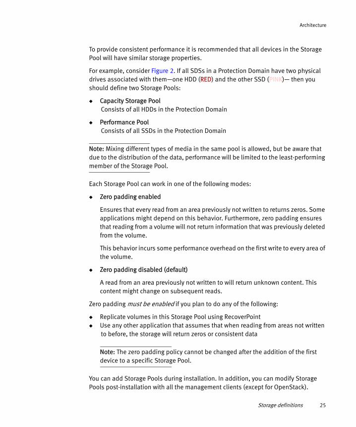
To provide consistent performance it is recommended that all devices in the Storage Pool will have similar storage properties.
For example, consider Figure 2. If all SDSs in a Protection Domain have two physical drives associated with them—one HDD (RED) and the other SSD (PINK)— then you should define two Storage Pools:
◆ Capacity Storage PoolConsists of all HDDs in the Protection Domain
◆ Performance PoolConsists of all SSDs in the Protection Domain
Note: Mixing different types of media in the same pool is allowed, but be aware that due to the distribution of the data, performance will be limited to the least-performing member of the Storage Pool.
Each Storage Pool can work in one of the following modes:
◆ Zero padding enabled
Ensures that every read from an area previously not written to returns zeros. Some applications might depend on this behavior. Furthermore, zero padding ensures that reading from a volume will not return information that was previously deleted from the volume.
This behavior incurs some performance overhead on the first write to every area of the volume.
◆ Zero padding disabled (default)
A read from an area previously not written to will return unknown content. This content might change on subsequent reads.
Zero padding must be enabled if you plan to do any of the following:
◆ Replicate volumes in this Storage Pool using RecoverPoint ◆ Use any other application that assumes that when reading from areas not written
to before, the storage will return zeros or consistent data
Note: The zero padding policy cannot be changed after the addition of the first device to a specific Storage Pool.
You can add Storage Pools during installation. In addition, you can modify Storage Pools post-installation with all the management clients (except for OpenStack).
Storage definitions 25

Architecture
You can add Storage Pools during installation. In addition, you can modify Storage Pools post-installation with all the management clients (except for OpenStack).
Fault Sets
A Fault Set is a logical entity that contains a group of SDSs within a Protection Domain, that have a higher chance of going down together, for example if they are all powered in the same rack. By grouping them into a Fault Set, you are telling ScaleIO that the data mirroring for all devices in this Fault Set, should take place on SDSs that are outside of this Fault Set.
When defining Fault Sets, we refer to the term fault units, where a fault unit can be either a Fault Set, or an SDS not associated with a Fault Set (you may think of it as a Fault Set of a single SDS).
There must be enough capacity within at least 3 fault units to enable mirroring.
If Fault Sets are defined, you can use any combination of fault units, for example:
◆ SDS1, SDS2, SDS3◆ FS1, SDS1, SDS2◆ FS1, FS2, SDS1◆ FS1, FS2, FS3
Figure 3 illustrates the same configuration as Figure 2, with the addition of Fault Sets.
Figure 3 Protection Domains, Storage Pools, and Fault Sets
26 EMC ScaleIO Installation Guide

Architecture
To use Fault Sets, you must work in the following order:
1. Ensure that a Protection Domain exists, or add a new one.
2. Ensure that a Storage Pool and Fault Sets (minimum of 3 fault units) exist, or add new ones.
3. Add the SDS, designating the PD and FS, and at the same time, adding the SDS devices into a Storage Pool.
The Installation Manager and VMware deployment wizard follow this order automatically.
You can only create and configure Fault Sets before adding SDSs to the system, and configuring them incorrectly may prevent the creation of volumes. An SDS can only be added to a Fault Set during the creation of the SDS.
You define Fault Sets and add SDSs to them during installation, using the following management tools:
◆ Installation manager◆ CLI◆ REST◆ Plug-in
In addition, you can also add Fault Sets when adding SDS nodes after initial installation.
Naming
It is recommended to name all ScaleIO objects with meaningful names. This will make it easier when defining volumes, associating them with applications, etc.
From the previous example, the Storage Pools can be named Capacity_Storage and Performance_Storage, which allows you to identify the different tiers.
As for Protection Domains, one example would be separating the SDSs used by the finance department from those used by the engineering department. This segregation of different departments is very beneficial in many aspects (security being one of them). Thus, one might name the domains as Financial-PD and Engineering-PD.
The Fault Sets could be called FS_Rack01 and FS_Rack02.
Storage definitions 27

Architecture
Protection and load balancingScaleIO maintains the user data in a RAID-1 mesh mirrored layout. Each piece of data is stored on two different servers. The copies are randomly distributed over the storage devices. Rebuild and rebalance processes are fully automated, but are configurable.
Rebuild
When a failure occurs, such as on a server, device or network failure, ScaleIO immediately initiates a process of protecting the data. This process is called Rebuild, and comes in two flavors:
◆ Forward rebuild is the process of creating another copy of the data on a new server. In this process, all the devices in the Storage Pool work together, in a many-to-many fashion, to create new copies of all the failed storage blocks. This method ensures an extremely fast rebuild.
◆ Backward rebuild is the process of re-synchronization of one of the copies. This is done by passing to the copy only changes made to the data while this copy was inaccessible. This process minimizes the amount of data transferred over the network during recovery.
ScaleIO automatically selects the type of rebuild to perform. This implies that in some cases, more data will be transferred to minimize the time that the user data is not fully protected.
Rebuild throttling
Rebuild throttling sets the rebuild priority policy for a Storage Pool. The policy determines the priority between the rebuild I/O and the application IO when accessing SDS devices. Please note that application I/Os are continuously served.
Applying rebuild throttling will on one hand increase the time the system is exposed with a single copy of some of data, but on the other hand, will reduce the impact on the application. One has to make a decision and choose the right balance between the two.
28 EMC ScaleIO Installation Guide

Architecture
The following possible priority policies may be applied:
◆ No Limit: No limit on rebuild I/Os.
Any rebuild I/O is submitted to the device immediately, without further queuing. Please note that rebuild I/Os are relatively large and hence setting this policy will speed up the rebuild, but will have the maximal effect on the application I/O.
◆ Limit Concurrent I/O: Limit the number of concurrent rebuild I/Os per SDS device (default).
The rebuild I/Os are limited to a predefined number of concurrent I/Os. Once the limit is reached, the next incoming rebuild I/O waits until the completion of a currently executed rebuild I/O. This will complete the Rebuild quickly for best reliability, however, there is a risk of host application impact.
◆ Favor Application I/O: Limit rebuild in both bandwidth and concurrent I/Os.
The rebuild I/Os are limited both in bandwidth and in the amount of concurrent I/Os. As long as the number of concurrent rebuild I/Os, and the bandwidth they consume, do not exceed the predefined limits, rebuild I/Os will be served. Once either threshold is reached, the rebuild I/Os wait until both I/O and bandwidth are below their thresholds. For example, setting the value to "1" will guarantee the device will only have one concurrent rebuild IO at any given moment, which will ensure the application IOs only wait for 1 rebuild IO at worst case.
This imposes bandwidth on top of the Limit Concurrent I/Os option, which is a prerequisite to using this policy.
◆ Dynamic Bandwidth Throttling: This policy is similar to Favor Application I/O, but extends the interval in which application I/Os are considered to be flowing by defining a minimal quiet period. This quiet period is defined as a certain interval in which no application I/Os occurred. Note that the limits on the rebuild bandwidth and concurrent I/Os are still imposed.
◆ Default Values: The default policy for rebuild is: Limit Concurrent I/O
• Rebuild concurrent I/O Limit: 1 concurrent I/O
Note: Rebuild throttling affects the system's performance and should only be used by advanced users.
Protection and load balancing 29

Architecture
Rebalance
Rebalance in the process of moving one of the data copies to a different server. It occurs when ScaleIO detects that the user data is not evenly balanced across the devices in a Storage Pool. This can occur as a result of several conditions such as: SDS addition/removal, device addition/removal, or following a recovery from a failure. ScaleIO will move copies of the data from the most utilized devices to the least utilized ones.
Both Rebuild and Rebalance compete with the application IO for the system resources. This includes network, CPU and disks. ScaleIO provides a very rich set of parameters that can control this resource consumption. While the system is factory-tuned for balancing between speedy rebuild/rebalance and minimization of the effect on the application IO, the user has very fine-grain control over the rebuild and rebalance behavior.
Rebalance throttling
Rebalance throttling sets the rebalance priority policy for a Storage Pool. The policy determines the priority between the rebalance I/O and the application IO when accessing SDS devices. Please note that application I/Os are continuously served. Rebalance, unlike rebuild, does not impact the system’s reliability and therefore reducing its impact is logical.
The following possible priority policies may be applied:
◆ No Limit: No limit on rebalance I/Os.
Any rebalance I/O is submitted to the device immediately, without further queuing. Please note that rebalance I/Os are relatively large and hence setting this policy will speed up the rebalance, but will have the maximal effect on the application I/O.
◆ Limit Concurrent I/O: Limit the number of concurrent rebalance I/Os per SDS device.
The rebalance I/Os are limited to a predefined number of concurrent I/Os. Once the limit is reached, the next incoming rebalance I/O waits until the completion of a currently executed rebalance I/O. For example, setting the value to "1" will guarantee that the device will only have one rebalance IO at any given moment, which will ensure that the application IOs only wait for 1 rebalance IO in the worst case.
30 EMC ScaleIO Installation Guide

Architecture
◆ Favor Application I/O: Limit rebalance in both bandwidth and concurrent I/Os.
The rebalance I/Os are limited both in bandwidth and in the amount of concurrent I/Os. As long as the number of concurrent rebalance I/Os, and the bandwidth they consume, do not exceed the predefined limits, rebalance I/Os will be served. Once either limiter is reached, the rebalance I/Os wait until such time that the limits are not met again.
This imposes a bandwidth limit on top of the Limit Concurrent I/Os option.
◆ Dynamic Bandwidth Throttling: This policy is similar to Favor Application I/O, but extends the interval in which application I/Os are considered to be flowing by defining a minimal quiet period. This quiet period is defined as a certain interval in which no application I/Os occurred. Note that the limits on the rebalance bandwidth and concurrent I/Os are still imposed.
◆ Default Values:
• The default policy for rebalance is: Favor Application I/O
• Rebalance concurrent I/O Limit: 1 concurrent I/O per SDS device
• Rebalance bandwidth limit: 10240 KB/s
Note: Rebalance throttling affects the system's performance and should only be used by advanced users.
NetworkingIn ScaleIO, inter-node communication (for the purposes of managing data locations, rebuild and rebalance, and for application access to stored data) can be done on one IP network, or on separate IP networks. Management (via any of the management interfaces) can be done in the following ways:
◆ Via a separate network with access to the other ScaleIO components
◆ On the same network
These options can be configured a) during deployment in the full Installation Manager (via the CSV topology file) and using the VMware plug-in, as well as b) after deployment with the CLI.
Networking 31

Architecture
This section describes how to choose from these options, depending on your organization's requirements, security considerations, performance needs, and IT environment.
ScaleIO networking considerations:
◆ Single IP networkAll communications and IOs used for management and for data storage are performed on the same IP network. This setup offers the following benefits:
• Ease of use
• Fewer IP addresses required
◆ Multiple separate IP networksSeparate networks are used for management and for data storage, or separate networks are used within the data storage part of the system. This setup offers the following benefits:
• Security
• Redundancy
• Performance
• Separate IP roles in order to separate between customer data and internal management
Note: Network high availability can be implemented by using NIC-bonding (refer to relevant operating system vendor guidelines for best practices) or by using several data networks in ScaleIO.
For more information about MTU performance considerations and best practices, see the EMC Fine-Tuning ScaleIO Performance Technical Notes.
32 EMC ScaleIO Installation Guide

Architecture
The following table describes the range of potential IP address configurations:
The following combinations can be used for SDS/SDC:
◆ Only SDS All IPs
◆ Only SDS-SDS Only IPs + SDS-SDC Only IPs
◆ SDS All IPs + either SDS-SDS Only IPs or SDS-SDC Only IPs (can be used in cases of multiple networks; ensure that you do not use the same IP address more than once in the networks).
◆ SDS All IPs + both SDS-SDS Only IPs and SDS-SDC Only IPs (can be used in cases of multiple networks; ensure that you do not use the same IP address more than once in the networks).
Table 4 IP address configurations in ScaleIO (based on CSV file)
Column in CSV file MDM Mgmt IP MDM IPs SDS All IPs SDS-SDS Only IPs SDS-SDC Only IPs
Comments Management Access
Control Network Rebuild and Data Path Network
Rebuild Network Data Path Network
Optional, but recommended; not applicable for Tie-BreakerIP addresses that can be used to provide access to ScaleIO management applications, such as CLI, GUI, REST API, OpenStack. This IP address must be externally accessible.
Mandatory
IP addresses used for MDM control communications with SDSs and SDCs, used to convey data migration decisions, but no user data passes through the MDM. Must be on the same network as the data network. Must be externally accessible if no MDM Management IP addresses are used.
IP addresses used for both SDS-SDS and SDS-SDC communications. These IP addresses will also be used to communicate with the MDM
IP addresses used for SDS-SDS communication only. These addresses are used for rebuild & rebalance operations.These IP addresses will also be used to communicate with the MDM.
IP addresses used for SDS-SDC communication. These addresses are only used for read-write user data operations.
Networking 37

Architecture
Note: On Windows and Linux, only the MDM needs a management IP address. On VMware, all ScaleIO VMs need to have a management IP address as well as another address for the data network, the network on which traffic flows between SDSs and SDCs for read/writes, rebuild, and rebalance.
In the following example drawing for separate networks, a very simple example is shown, where the management and storage parts of the system are on different networks. In more complex configurations, MDMs, SDCs and SDSs can be on separate networks. Up to 8 separate networks per ScaleIO system are supported.
VMware limitation:
Multiple IP subnets used for the ScaleIO Data network cannot be on the same subnet in a VMWare setup.
For more information, see the VMWare limitation in the following link:
http://kb.vmware.com/selfservice/microsites/search.do?language=en_US&cmd=displayKC&externalId=2010877
ScaleIO only supports the following network configurations when deployed on VMware:
◆ A single data storage network
◆ Two or more data networks, each on separate IP subnets
◆ A single IP data network using several NIC-bonding configurations, or vSwitch load balancing
The following figures show example configurations and the corresponding fields in a CSV configuration file.
38 EMC ScaleIO Installation Guide

Architecture
Figure 4 ScaleIO system deployed on a single network (Windows)
Networking 35

Architecture
Figure 5 ScaleIO system deployed on separate networks (Windows)
Implementing ScaleIOImplementing a ScaleIO system is, in general, a two-step process: first build the physical storage layer, then configure the virtual SAN layer on top of it.
Physical layer
The physical layer consists of the hardware (servers with storage devices and the network between them) and the ScaleIO software installed on them.
36 EMC ScaleIO Installation Guide

Architecture
To implement the physical layer, perform the following steps:
1. Install the MDM component on the MDM nodes, either three nodes (two MDM and one Tie-Breaker) for a redundant management cluster in Cluster MDM, or a single node in case of a Single MDM.
It is not recommended to use Single Mode in production systems, except in temporary situations. The MDM contains all the metadata required for system operation. Single Mode has no protection, and exposes the system to a single point of failure.
Note: MDMs do not require dedicated nodes. They can be installed on nodes hosting other ScaleIO components.
2. Install the SDS component on all nodes that will contribute some, or all, of their physical storage.
Divide the SDS nodes into Protection Domains. Each SDS can be a member of only one Protection Domain. Per Protection Domain, divide the physical storage units into Storage Pools, and optionally, into Fault Sets.
3. Install the SDC component on all nodes on which the application will access the data exposed by the ScaleIO volumes.
Implementing ScaleIO 37

Architecture
Figure 6 Physical layout example
Communication is done over the existing LAN using standard TCP/IP. The MDM and SDS nodes can be assigned up to eight IP addresses, enabling wider bandwidth and better I/O performance and redundancy.
You can perform physical layer setup using the following methods:
◆ ScaleIO Installation Managera CLI or web-client based tool, described in Chapter 3, “Installing on Physical Servers.”
◆ ScaleIO VMware plug-ina VMware plug-in, described in Chapter 4, “Installing on ESX Servers.”
◆ Manual installationmanual installation procedures, described in Appendix A, “Manual Installation.”
After completing this installation, the physical layer is ready, and it exposes a virtual storage layer.
38 EMC ScaleIO Installation Guide

Architecture
SAN virtualization layer
The MDM cluster manages the entire system. It aggregates the entire storage exposed to it by all the SDSs to generate a virtual layer - virtual SAN storage. Volumes can now be defined over the Storage Pools and can be exposed to the applications as a local storage device using the SDCs.
To expose the virtual SAN devices to your servers (the ones on which you installed and configured SDCs), perform the following:
◆ Define volumesEach volume defined over a Storage Pool is evenly distributed over all members using a RAID protection scheme. By having all SDS members of the Storage Pool participate, ScaleIO ensures:
• Highest and most stable and consistent performance possible
• Rapid recovery and redistribution of data
• Massive IOPS and throughput
You can define volumes as thick, where the entire capacity is provisioned for storage, or thin, where only the capacity currently needed is provisioned.
◆ Map volumesDesignate which SDCs can access the given volumes. This gives rise to the following:
• Access control per volume exposed
• Shared nothing or shared everything volumes
Once an SDC is mapped to a volume, it immediately gets access to the volume and exposes it locally to the applications as a standard block device. These block devices appear as /dev/sciniX where X is a letter, starting from “a.”
For example:
◆ /dev/scinia
◆ /dev/scinib
Implementing ScaleIO 39
Architecture
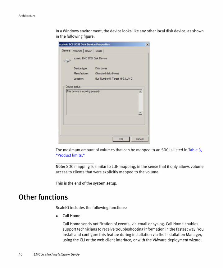
In a Windows environment, the device looks like any other local disk device, as shown in the following figure:
The maximum amount of volumes that can be mapped to an SDC is listed in Table 3, “Product limits.”
Note: SDC mapping is similar to LUN mapping, in the sense that it only allows volume access to clients that were explicitly mapped to the volume.
This is the end of the system setup.
Other functionsScaleIO includes the following functions:
◆ Call Home
Call Home sends notification of events, via email or syslog. Call Home enables support technicians to receive troubleshooting information in the fastest way. You install and configure this feature during installation via the Installation Manager, using the CLI or the web client interface, or with the VMware deployment wizard.
40 EMC ScaleIO Installation Guide

Architecture
◆ Get Info
Get Info enables you to assemble a ZIP file of system logs for troubleshooting. You can run this function from a local node for its own logs, or by using the Installation Manager to assemble logs from all MDM and SDS nodes in the system.
◆ Quality of Service (QoS)
You can adjust the amount of bandwidth and storage that any given SDC can use. You can configure this with the CLI and the REST interface, on a per client/per volume basis.
◆ Obfuscation
Data on ScaleIO volumes can be obfuscated for higher data protection. You can configure this with the CLI and the REST interface, on a per VTree basis.
◆ Background Device Scanner
The Background Device Scanner ("scanner") enhances the resilience of your ScaleIO system by constantly searching for, and fixing, device errors before they can affect your system. This provides increased data reliability than the media's checksum scheme provides. The scanner seeks out corrupted sectors of the devices in that pool, provides SNMP reporting about errors found, and keeps statistics about its operation.
When a scan is completed, the process starts again, thus adding constant protection to your system.
You can set the scan rate (default: 1 MB/second per device), which limits the bandwidth allowed for scanning, and choose from the following scan modes:
• Device only mode
The scanner uses the device's internal checksum mechanism to validate the primary and secondary data. If a read succeeds in both devices, no action is taken. If a faulty area is read, an error will be generated.
If a read fails on one device, the scanner attempts to correct the faulty device with the data from the good device. If the fix succeeds, the error-fixes counter is increased. If the fix fails, a device error is issued.
Note: A similar algorithm is performed every time an application read fails on the primary device.
If the read fails on both devices, the scanner skips to the next storage block.
Other functions 41

Architecture
• Data comparison mode (only available if zero padding is enabled)
The scanner performs the same algorithm as above, with the following additions:
After successful reads of primary and secondary, the scanner calculates and compares their checksums. If this comparison fails, the compare errors counter is increased, and the scanner attempts to overwrite the secondary device with the data from the primary device. If this fails, a device error is issued.
The scanning function is enabled and disabled (default) at the Storage Pool level, and this setting affects all devices in the Storage Pool. You can make these changes at anytime, and you can add/remove volumes and devices while the scanner is enabled.
When adding a device to a Storage Pool in which the scanner is enabled, the scanning will start about 30 seconds after the device is added.
MaintenanceMaintenance of ScaleIO is primarily limited to configuration changes of the physical and virtual layers. It requires minimal user attention.
Maintaining the physical layer
In the physical layer, maintenance is limited to adding and removing hardware units and configuring them into the ScaleIO system. These operations are usually a result of:
◆ Scaling outWhen there is a need for additional capacity. This usually results in adding more storage media to the existing nodes, or adding additional nodes.
◆ Upgrading or re-purposing hardwareWhen system servers are being replaced, either as a result of application needs, ScaleIO needs (where the storage capacity is limited and you would like to add more), or a system refresh.
◆ Hardware failureWhen there is a hardware (storage media, nodes) failure, and it needs to be replaced.
42 EMC ScaleIO Installation Guide

Architecture
In all of the above cases, the operation will require adding or removing storage capacity from the system. In some cases, it may include adding or removing an entire node, and its associated storage media, from the configuration. As far as ScaleIO is concerned, all of these activities translate to SDS reconfigurations.
If the removed node is an SDC node, or the node to be added requires exposing storage locally, SDC reconfiguration will happen as well.
◆ Adding or removing storage mediaAdd or remove the media from the SDS with which it is associated. ScaleIO will redistribute the data accordingly and seamlessly.
◆ Adding or removing a nodeAdd or remove the SDC and SDS residing on the node. ScaleIO will redistribute the data accordingly and seamlessly.
Maintaining the virtualization layer
The following operations may be done to volumes that are exposed by the ScaleIO virtual SAN:
◆ Add or remove a volumeCreate or delete a volume in the system.
◆ Increase volume sizeAdd capacity to a given volume, as needed. The change in volume size occurs seamlessly without interrupting I/O.
◆ Map and unmap volumes to an SDCThis enables or disables access to a volume by an SDC, and thus by an application residing on the same node.
SnapshotsThe ScaleIO storage system enables you to take snapshots of existing volumes, up to 31 per volume. The snapshots are thinly provisioned and are extremely quick. Once a snapshot is generated, it becomes a new, unmapped volume in the system. You can manipulate it in the same manner as any other volume exposed by the ScaleIO storage system.
Snapshots 43

Architecture
Figure 7 Snapshot operations
The structure related to all the snapshots resulting from one volume is referred to as a VTree (short for Volume Tree). It’s a tree spanning from the source volume as the root, whose siblings are either snapshots of the volume itself or descendants of it. Thus, some snapshot operations are related to the VTree, and may affect parts of it. In Figure 7 in BLUE, S111 and S112 are snapshots of V1. S121 is a snapshot of snapshot S111. Together, V1 and S1xy are the VTree of V1.
When taking a snapshot in the system, you can specify more than one volume. All snapshots taken together form a consistency group. They are consistent in the sense that they were all taken at the same time. So if there is a contextual relationship between the data contained by all the snapshot members, then that set is meaningful. The consistency group allows manipulation of the entire set.
If you remove an entire consistency group, all of the snapshots that were taken together will be removed. Back to Figure 7, in RED, S211 is a snapshot of V2. Since S112 and S211 were taken together, they compose a consistency group (in ORANGE) designated as C1.
Note: The consistency group is only for convenience purposes. There are no protection measures done by ScaleIO to conserve the consistency group. For example, you can remove a snapshot that is a member of a consistency group.
44 EMC ScaleIO Installation Guide

Architecture
Snapshot operations
The following operations are snapshot related. Since all snapshots are volumes in the system, all volume operations are applicable to snapshots.
◆ Take a snapshot of a volume
The snapshot_volume command allows a snapshot of a given volume. When specifying more than one volume (a list), a consistency group is generated.
◆ Map volume to an SDC
The map_volume_to_sdc command maps the snapshot volume to an SDC and thus exposes it to the applications. This is no different than any other volume mapping operation.
◆ Remove a volume
The remove_volume command affects snapshots in several ways. Since snapshots are volumes, the way to delete a snapshot is exactly the same as removing a volume from the system.
Management toolsYou can provision, maintain, and monitor ScaleIO with the following management clients, described in the EMC ScaleIO User Guide:
◆ Command Line Interface (CLI)
The CLI enables you to perform the entire set of configure, maintain, and monitor activities in a ScaleIO system.
◆ Graphical User Interface (GUI)
The GUI enables you to perform standard configure and maintain activities, as well as to monitor the storage system’s health and performance. You can use the GUI to view the entire system, and then drill down to different elements. The GUI cannot be used for frontend, i.e., volume management.
◆ VMware plug-in (plug-in)
The plug-in enables you to perform basic provision and maintain activities in the VMware environment. In addition, the plug-in provides a wizard to deploy ScaleIO in the VMware environment.
Management tools 45

Architecture
◆ OpenStack
ScaleIO provides Cinder and Nova drivers, which enable interoperation between a ScaleIO system and an OpenStack cloud operating system.
◆ REST Gateway
A REST API can be used to expose monitoring and provisioning via the REST interface. The REST API is installed as part of the ScaleIO Gateway.
Many ScaleIO activities can be performed in an option of various management tools.
The following tool is also provided:
◆ Installation Manager (IM)
The IM is used for installing ScaleIO, upgrading and uninstalling components, as well as running the get-info operation. The IM is installed as part of the ScaleIO Gateway.
Configuring direct attached storage (DAS)ScaleIO works with any free capacity—internal or direct-attached devices, either magnetic hard disk drives (HDD) or flash-based devices such as solid state drive (SSD) and PCIe cards. Although ScaleIO can work with any device topology, it is recommended to configure the raw devices as stand-alone devices.
If the server has a RAID controller, ScaleIO prefers to use the controller’s caching abilities for better performance, but is better utilized when all devices are configured as stand-alone (i.e. setting each of the devices to RAID-0 separately). For HDD devices, it is recommended to enable RAID-controller caching. As for flash devices, it depends on the device behavior.
For Windows, when using a physical disk drive, it is recommended to generate a single, unformatted partition over the entire disk.
For more information about preparing Windows devices, see “Adding devices to SDS nodes on Windows servers” on page 155.
Note: For HDDs: It is recommended to use RAID-controller caching when available as follows:READ/WRITE: if cache is battery-backed
46 EMC ScaleIO Installation Guide

Architecture
READ ONLY: if cache is NOT battery-backed
For flash devices (e.g. SSD): Depends on the device
Implementing ScaleIO over a virtual systemThis section provides an overview of how ScaleIO is implemented in virtual environments.
VMware
In the VMware environment, the MDM and SDS components are installed on a dedicated SVM, whereas the SDC is installed directly on the ESX host.
Note: Installing the SDC on the ESX host requires a restart of the ESX host.
This implementation is illustrated in the following figure:
Figure 8 ScaleIO implementation on ESX
Implementing ScaleIO over a virtual system 47

Architecture
Note: The LUNs in the previous figure can be formatted with VMFS, and then exposed using the ESXi host to the virtual machine, or can be used as RDM devices. When the LUNs are used as RDM devices, the VMFS layer is omitted.
Installation in a VMware environment is enabled via the VMware plug-in. For more information, see Chapter 4, “Installing on ESX Servers.”
Xen implementation
In a Xen environment, both the SDC and SDS are installed in Dom0 as would be on a physical node. Dom0 accesses the storage media through the SDS and exposes volumes based on ScaleIO through the SDC.
Figure 9 ScaleIO Xen virtual machine architecture
For information on provisioning in a Xen environment, see the EMC ScaleIO User Guide.
48 EMC ScaleIO Installation Guide

PART 2
Deploying ScaleIO Systems
The chapters in this part of the guide describe how to get ScaleIO started in your environment. Chapters include:
Chapter 3, “Installing on Physical Servers”
This chapter describes how to install the ScaleIO Gateway and deploy ScaleIO components on physical servers.
Chapter 4, “Installing on ESX Servers”
This chapter describes how to install the ScaleIO Gateway and deploy ScaleIO components on ESX servers.


CHAPTER 3Installing on Physical Servers
This chapter describes how to install, deploy, and perform initial configuration of ScaleIO software components on physical servers. Topics include:
◆ Preparing the Installation Manager and the Gateway ........................................ 52◆ Installing with the full Installation Manager ...................................................... 56◆ Installing with the Installation Manager wizard ................................................. 75◆ Installing the ScaleIO GUI................................................................................. 81◆ Configuring the Installation Manager ................................................................ 82
Note: ScaleIO installation enables unlimited use of the product, in non-production environments. To obtain a license for production use, and to receive technical support, open a service ticket with EMC Support at https://support.emc.com.
For complete information on licensing, see the EMC ScaleIO User Guide.
In physical environments, and in non-VMware virtual environments (Xen, Hyper-V, and KVM), you use the ScaleIO Installation Manager (IM) to install and configure the ScaleIO components on multiple nodes from one central server, via a CLI interface or a web client.
The Installation Manager can be used to install numerous ScaleIO systems, from one central workstation.
Note: The IM can be disabled and configured, as described in “Configuring the Installation Manager” on page 82.
Installing on Physical Servers 51

Installing on Physical Servers
As part of the installation process, the ScaleIO Lightweight Installation Agent (LIA) is installed. The LIA’s seamless communication enables future upgrades, the Get Info operation, as well as uninstalling, without the need for an updated CSV topology file. During initial installation, the IM establishes trust with the LIA, which facilitates its operation.
Hint: To make changes to the LIA configuration file, see “Changing the LIA configuration file” on page 188.
You can limit the operations that LIA can perform by making changes to its configuration file. In Windows environments, LIA will only install and upgrade packages that are signed by ScaleIO and associated with the ScaleIO system.
Preparing the Installation Manager and the GatewayBefore installing ScaleIO, you must prepare the Installation Manager (IM). The Installation Manager is installed as part of the ScaleIO Gateway. The Gateway includes the REST Gateway and the SNMP trap sender functionality, too. In this document, the terms IM server and Gateway server are synonymous.
You can enable and disable Gateway components, as described in “Enabling and disabling Gateway components” on page 147.
The Gateway can be installed on the same node as other ScaleIO components. Ensure that the node has adequate memory to run the IM (minimum of 2 GB) and any other applications.
To install ScaleIO on Linux nodes, the IM server can be a Windows or Linux server. To install ScaleIO on Windows nodes, or to install in a mixed-OS environment, your IM server must be a Windows server. The IM server must have connectivity to both the data and management ScaleIO networks.
Ensure that your IM server meets the system requirements described in Table 2, “System requirements for ScaleIO Gateway.”
52 EMC ScaleIO Installation Guide

Installing on Physical Servers
Which installation mode is best for you?
The Installation Manager can be used in the following modes:
◆ Full IM
This mode, which enables the highest level of customization, uses a user-prepared CSV topology file to install ScaleIO and configure nodes. The CSV file is used by the IM to set up and configure all the nodes. To add additional servers after the initial installation, you will also use the combination of CSV topology file and IM.
◆ IM wizard
This abbreviated mode enables you to get a ScaleIO system up and running in the simplest manner, with preset node configuration, where all management and data communication are on the same network. This mode is perfect for a single Protection Domain, fully-converged system. No CSV file is required.
After preparing the IM, you can choose which mode to use.
This section describes the steps required to prepare the ScaleIO Installation Manager (IM). Proceed to the section that matches the operating system of your IM server:
◆ “Preparing the IM on a Linux server” on page 53
◆ “Preparing the IM on a Windows server” on page 55
Preparing the IM on a Linux server
This section describes how to prepare the Installation Manager (IM) on a Linux server. You can use a Linux IM to deploy to Linux servers only.
1. Download and extract the installation files needed for your operating system. This would include, minimally, the files for the ScaleIO Gateway and components.
Hint: Alternatively, you can download the Complete Software Download, that contains all files for all operating systems.
You may also want the files to install the GUI.
You need the Components ZIP file for your Linux operating system as well as the Gateway for Linux. The GUI for Linux is a separate file.
You can download all files from EMC Online Support (https://support.emc.com).
Preparing the Installation Manager and the Gateway 53

Installing on Physical Servers
Hint: To install with a customized Java configuration, see “Using a custom Java configuration for the Gateway” on page 148.
2. From the extracted download file, install the ScaleIO Gateway on the Linux IM server, by running the following command (all on one line):
GATEWAY_ADMIN_PASSWORD=<new_GW_admin_password> rpm -U /tmp/EMC-ScaleIO-gateway-1.32-XXX.X.noarch.rpm
where <new_GW_admin_password> is a password that you define to access the IM
Hint: To install without assigning a Gateway password, see “Installing the Gateway without assigning an admin password” on page 149.
Note: If your Linux IM server has JRE 1.7 or higher, add the --nodeps flag.
3. When installing on XEN servers, add the following changes to the /opt/emc/scaleio/gateway/conf/server.xml file:
a. Edit the Connector port="80" protocol="HTTP/1.1 class, as follows:
Change redirectPort from 443 to 8443.
b. Edit the Connector port="443" protocol="org.apache.coyote.http11.Http11NioProtocol" header, as follows:
Change Connector port from 443 to 8443.
c. Restart the scaleio-gateway service.
4. Choose which IM mode to use:
• To use the IM wizard, skip to “Installing with the Installation Manager wizard” on page 75.
• To use the full IM to install ScaleIO and the replication splitter for RecoverPoint, continue with “Installing the replication splitter for RecoverPoint” on page 54.
• To use the full IM to install ScaleIO only, continue with “Installing with the full Installation Manager” on page 56.
Note: You can configure the Installation Manager, as described in “Configuring the Installation Manager” on page 82
Installing the replication splitter for RecoverPoint
Note: If you are not installing the replication splitter for RecoverPoint, skip to “Installing with the full Installation Manager” on page 56.
54 EMC ScaleIO Installation Guide

Installing on Physical Servers
This section describes steps that are required when using the IM to install the replication splitter for RecoverPoint. There are additional post-installation configurations steps. For full instructions, refer to the EMC ScaleIO Write Splitter for RecoverPoint Technical Notes before beginning the installation.
To install the replication splitter for RecoverPoint, you must do the following:
◆ Enable zero-padding on the Storage Pools, as described in “Configuring the Installation Manager” on page 82.
◆ In the installation CSV file:
• Add the Splitter RPA IP column, and enter the information, as described in “Preparing the CSV topology file” on page 56.
• In the Optimize IOPS column, set the value to Yes.
◆ Upload the splitter package to the IM server.
Continue with “Installing with the full Installation Manager” on page 56.
Preparing the IM on a Windows server
This section describes how to prepare the Installation Manager (IM) on a Windows server. You can use a Windows IM to deploy to Windows and Linux servers.
1. Download and extract the installation files needed for your operating system. This would include, minimally, the files for the ScaleIO Gateway and components.
You may also want the files to install the GUI.
All ScaleIO files are located in the Complete Windows Software Download ZIP.
Hint: To use this Gateway to deploy ScaleIO on Linux nodes, too, you should also download the ScaleIO components for the relevant Linux OS.
You can download all files from EMC Online Support (https://support.emc.com).
2. From the extracted download file, copy the ScaleIO Gateway MSI to the IM server:
• 32-bit: EMC-ScaleIO-gateway-1.32-XXX.X-x86.msi• 64-bit: EMC-ScaleIO-gateway-1.32-XXX.X-x64.msi
Note: The bit version of the Gateway version you install must match the same bit version of the Java that is installed.
3. Run the file, enter (and confirm) a new Gateway Admin password that will be used to access the IM.
Preparing the Installation Manager and the Gateway 55

Installing on Physical Servers
Hint: To add more devices than the amount of available drive letters, and for other options, see “Adding devices to SDS nodes on Windows servers” on page 155.
4. Prepare disks for storage:
a. Ensure that devices to be used are on-line, and initialized as MBR or GPT.
b. On each disk, use the Windows Disk Management to create a new, simple volume. Assign a drive letter, and select Do not format this volume.
5. Choose which IM mode to use:
• To use the IM wizard, skip to “Installing with the Installation Manager wizard” on page 75.
• To use the full IM, continue with “Installing with the full Installation Manager” on page 56.
Note: You can configure the Installation Manager, as described in “Configuring the Installation Manager” on page 82
Installing with the full Installation ManagerThis section describes how to use the full Installation Manager to install ScaleIO components. To use the IM wizard, go to “Installing with the Installation Manager wizard” on page 75.
Note: ScaleIO installation enables unlimited use of the product, in non-production environments. To obtain a license for production use, and to receive technical support, open a service ticket with EMC Support at https://support.emc.com.
For complete information on licensing, see the EMC ScaleIO User Guide.
To use the full Installation Manager, you must first prepare a CSV topology file.
Preparing the CSV topology file
You can edit a CSV with Excel or file-editing software. In this document, we will refer to and illustrate the CSV as a spreadsheet.
56 EMC ScaleIO Installation Guide

Installing on Physical Servers
The following CSV templates are provided as part of the software download, in the Gateway software packages:
◆ Complete
This spreadsheet template contains all available fields, both required and optional.
◆ Minimal
This spreadsheet template contains only the required fields. The optional fields (those that are in the complete spreadsheet, but not in the minimal one) will be assigned default values.
Hint: The CSV can also be used for removing installed components.
You should fill in your site-specific information in the appropriate places, overwriting the default information provided in the file.
You only need to use one spreadsheet for the installation, as follows:
◆ To manually enter all configuration details, use the Complete spreadsheet.
◆ To use default values for the non-mandatory fields, use the Minimal spreadsheet.
◆ To configure non-default values for columns that are not in the Minimal spreadsheet, either use the Complete spreadsheet, or copy the column heading from there into the minimal spreadsheet and enter your custom values into the minimal spreadsheet.
You can use either spreadsheet to assign as many as eight IP addresses per MDM and SDS.
The following example portrays a CSV for adding several Linux nodes, and the same nodes in Windows. You can use the same spreadsheet to define nodes of multiple operating systems.
Figure 10 CSV—Linux example
Installing with the full Installation Manager 57

Installing on Physical Servers
Figure 11 CSV—Windows example
Note: The only difference between the Linux example and the Windows example is the first two columns in the Windows example, Domain and username, that are not relevant in the Linux environment.
The following table describes the fields in the spreadsheets. The required fields appear in both spreadsheets.
Table 5 CSV topology spreadsheets
Field Description Required
DomainIf using a domain user, the name of the domain (not relevant for Linux)
Username
The name of the user. In Linux, this value is always root; in Windows, a user with administrator rights (default: administrator).
IPs
IP of the node.
Note: Entering IP addresses in this column will use the same IP addresses for management and data IP addresses for all nodes. To separate the IP roles, leave this column blank, and use the MDM Mgmt IP and MDM IPs columns instead.
Yes1
Password
Password used to log in to the node. In Linux, the root password. In Windows, the password of a user with administrator rights.
Yes
Operating System The server’s OS: linux or windows Yes
Is MDM/TB Primary, Secondary, TB, or blank Yes
58 EMC ScaleIO Installation Guide

Installing on Physical Servers
MDM Mgmt IP The IP address for the management-only network
MDM IPs
MDM IP addresses used to communicate with other ScaleIO components in the storage network. Comma-separated, no spaces.
Is SDS Yes or No Yes
SDS Name The name for the SDS node
SDS All IPsSDS IP addresses to be used for communication among all nodes. Comma-separated, no spaces.
SDS-SDS Only IPsSDS IP addresses to be used for communication among SDS nodes only. Comma-separated, no spaces.
SDS-SDC Only IPs
SDS IP addresses to be used for communication among SDS and SDC nodes only. Comma-separated, no spaces.
Note: For SDC-only nodes, enter the IP in this column.
Protection Domain The Protection Domain to which to assign this SDS.
Fault Set
The Fault Set to which to assign this SDS.
Note: When using Fault Sets, you must assign a minimum of three, and follow the guidelines described in “Fault Sets” on page 26.
SDS Device List
The devices to add to the SDS, for example: Linux /dev/sdb,/dev/sdc or Windows d,e,f. Comma-separated, no spaces.2
Balance the total device capacity over all SDSs.
Note: Before adding Windows SDS devices see “Adding devices to SDS nodes on Windows servers” on page 155.
SDS Device Names
Sets user-defined device names. When using this field, the device names will be appropriated to the devices in the device list, respectively. The amount of names must equal the amount of devices. Comma-separated, no spaces.
Table 5 CSV topology spreadsheets
Field Description Required
Installing with the full Installation Manager 59

Installing on Physical Servers
1. This field is required, unless you specify separate data and management IP addresses.
2. To enable volume creation, you must add (at least) one device to (at least) 3 SDSs, where each SDS is in a separate fault unit, and each device has a minimum of 100 GB free storage capacity. You can do that via the CSV, or at a later stage.
Note: All fields are case-sensitive; the order of the columns is not significant.
Proceed with the section that describes which method of installation you are using:
◆ “Installing with the CLI” on page 61
◆ “Installing with the web client” on page 66
SDS Pool List
Sets Storage Pool names. When using this field, the Storage Pools will be appropriated to the devices in the device list, respectively. The amount of Storage Pools must equal the amount of devices. Comma-separated, no spaces.
Note: If no Storage Pool is set, one will be automatically created during installation, named default.
Optimize IOPS
Optimize SDS parameters when using fast devices, such as SSD. Yes or No.
Note: To use the replication splitter for RecoverPoint, set this value to Yes.
Is SDC Yes or No Yes
Splitter RPA IP
To install the replication splitter for RecoverPoint on an SDC, add this column to your spreadsheet, and enter the IP address that represents the RecoverPoint cluster IP address (RecoverPoint floating IP), configured during Splitter installation. Splitter installation will be successful only if an SDC is already installed and if iscsi-initiator-utils is supported.
Note: Only installations on RH6.X are supported.
Table 5 CSV topology spreadsheets
Field Description Required
60 EMC ScaleIO Installation Guide

Installing on Physical Servers
Installing with the CLI
This section describes how to install and configure ScaleIO components using the IM via the CLI.
Hint: You can install in automated, non-interactive mode, for scripting. For more information, see “Automated installation of ScaleIO components” on page 156.
The installation performs the following phases:
◆ QueryValidates that there are no previously-installed ScaleIO components on the nodes
Note: When using the IM to install the replication splitter for RecoverPoint, this step is not performed on the SDC nodes.
◆ UploadUploads the installation packages to the IM
◆ InstallInstalls the installation packages on the nodes
◆ ConfigureConfigures the installed ScaleIO components
To install, perform the following:
1. Download and launch the CLI:
Note: You can download the CLI from the IM server, and run it from any PC.
a. Open web browser with the following URL:https://<IM_server_IP>
where <IM_Server_IP> is the IP address of the server where you installed the IM package
b. Accept the certificate warning; alternatively, install your own certificate for the Tomcat server.
c. Log in with the default user name, admin, with the password defined when the IM was prepared, then click Login.
d. Click Download CLI and save the .jar file.
Installing with the full Installation Manager 61

Installing on Physical Servers
Hint: This section describes a subset of the IM CLI commands. For a full list, see “Installation Manager CLI commands” on page 158, or run the help command. For detailed help on any command, type help <command>.
e. Launch the CLI by running java -jar install-CLI.jar from the directory to which you downloaded the .jar file.
The IM CLI window appears. You issue all CLI installation commands in this window.
To see the format of a specific command, type the command without flags.
Note: All commands processed through the IM CLI are written to a log file, ScaleIO Installation Manager CLI.log, which is located in the same folder as the install-CLI.jar file. After the session completes, you can delete the log file.
2. Log in to the IM, by running the following command:
Hint: You can change the port, as described in “Changing default ports” on page 193.
im login --host <hostname/ip> --port <443> --username <user name> --password <admin_password> --cer <certificate_path> --java_flag <java_path>
Hint: When supplying a certificate path, it is recommended to include the --java_flag flag. For more information, see “Fixing keytool errors” on page 190.
Where certificate_path is the path to the certificate file of the gateway you want to connect. You can export this file from the browser, or copy it from the Gateway server:
• Windows—<gateway installation folder>\temp\certificates\ScaleIO.cer• Linux—<gateway installation folder>/temp/certificates/ScaleIO.cerExample:
im login --host 10.76.60.189 --port 443 --username admin --password Scaleio123 --cer /opt/emc/scaleio/gateway/temp/certificates/ScaleIO.cer --java_flag <java_path>
Note: If the IM CLI is used in remote mode, you must copy the certificate to that node, and point to its location.
You can also use the following flags:
• --no_certificate_validationWhen set to true, the CLI doesn’t validate the certificate when connecting to the Gateway.
62 EMC ScaleIO Installation Guide

Installing on Physical Servers
Example:
im login --host 10.76.60.189 --port 443 --username admin --password Scaleio123 --no_certificate_validation true
• --java_pathIf the Java path isn’t set, the CLI will attempt to locate it. To prevent keytool errors, it is highly recommended to use this flag when supplying a certificate.
3. Upload installation packages:
a. From the CLI window, upload packages to IM server by running the following command:
im upload_package --path <path to package>
Example:
– Windows (one MSI per component)
im upload_package --path c:\Scaleio\packages\EMC-ScaleIO-<component>-1.32-XXX.X.msi
where component is the name of the component to upload– Linux (one package per component)
im upload_package --path c:\Scaleio\packages\EMC-ScaleIO-<component>-1.32-XXX.X.el6.x86_64.rpm
where component is the name of the component
b. Repeat the previous step for each component package to upload:
– mdm– tb– callhome– sds– sdc– lia– splitter
Note: The version of the splitter file should match the version listed in the compatibility matrix in the EMC ScaleIO Write Splitter for RecoverPoint Technical Notes.
Installing with the full Installation Manager 63

Installing on Physical Servers
c. After the upload is complete, verify that the upload succeeded, by running the following command:
im list_packages
A list of uploaded packages, similar to the following, appears:
Uploaded packages:Filename: EMC-ScaleIO-lia-1.32-1.2.el6.x86_64.rpm - Type: lia - OS: linux, size: 9261062Filename: EMC-ScaleIO-callhome-1.32-1.2.el6.x86_64.rpm - Type: callhome - OS: linux, size: 21409...Filename: EMC-ScaleIO-tb-1.32-1.2.el6.x86_64.rpm - Type: tb - OS: linux, size: 8826981Filename: EMC-ScaleIO-setup-1.32-1.2.msi - Type: setup - OS: windows, size: 4410674Filename: EMC-ScaleIO-mdm-1.32-1.2.el6.x86_64.rpm - Type: mdm - OS: linux, size: 28159278
Note: In the example above, there are packages for RHEL 6 and Windows.
4. Start the installation from the CLI window, by running the following command:
im install --path <path to CSV file> --mdm_password <New MDM login password> [--lia_password <LIA password>] [--non-interactive]
where New MDM login password is a new password for the MDM that will be automatically configured, during the installation
where LIA password is the password that will be used to authenticate communication between the IM and the LIA
Note: If you do not enter a LIA password, the LIA will not be installed.
The passwords must meet the following criteria:
• Between 6 and 31, ASCII-printable characters
• No blank spaces
• Include at least 3 of the following groups: [a-z], [A-Z], [0-9], special chars (!@#$ …)
Example:
im install --path c:\installationmanager\new_local.csv --mdm_password Scaleio123 --lia_password ScaleioLIA456
64 EMC ScaleIO Installation Guide

Installing on Physical Servers
Note: You can use the --non_interactive flag to install in non-interactive mode. In this mode, which enables automated installation, you progress from one installation stage to the next by entering one of the following commands, instead of pressing a key, for example:
im set_upload_stateim set_install_stateim set_configure_state
For an example of how to use this mode for automated installation, see “Automated installation of ScaleIO components” on page 156.
The installation progress appears on the screen, similar to the following:
Running...7 commands remaining..1 commands remainingAll commands completed successfullyPress (r) to retry failed or aborted commands (if any), or (p) to proceed and finishDone
The installation performs the following phases: query, upload, install, and configure.
5. Follow the installation progress, and press a key to proceed from stage to stage, as follows:
◆ Press p to proceed to the next stage.
◆ If any tasks failed or were aborted, you can press r to retry. After you proceed to the next installation phase, you will not be able to use the IM to retry failed tasks.
When the installation completes, the following message appears:
All commands completed successfullyPress (r) to retry failed or aborted commands (if any), or (p) to proceed and finishDone
6. Install the GUI, as described in “Installing the ScaleIO GUI” on page 81.
Installing with the full Installation Manager 65

Installing on Physical Servers
Best practice suggestionFor optimal performance in environments with more than 60,000 IOPS, see the Fine-Tuning ScaleIO Performance Technical Notes.
Where to go from hereNow that your ScaleIO system is up and running, the next task is to create volumes. The SDCs expose these volumes as local storage devices to the applications servers. For more information, see “SAN virtualization layer” on page 39.
You can create and map volumes using the ScaleIO CLI, as described in the EMC ScaleIO User Guide.
To enable the SNMP feature, see “Enabling and disabling Gateway components” on page 153.
Installing with the web client
This section describes how to install and configure ScaleIO components using the Installation Manager via the web client.
You need to do the following steps:
◆ “Log in to the IM server” on page 66
◆ “Upload installation packages” on page 67
◆ “Upload CSV file” on page 68
◆ “Initiate the installation” on page 69
◆ “Complete the installation” on page 71
Log in to the IM server
1. Log in to: https://<IM_Server_IP>
where <IM_Server_IP> is the IP address of the server where you installed the IM package
2. Accept the certificate warning; alternatively, install your own certificate for the Tomcat server.
3. Enter the default user name, admin, and the password defined when the IM was prepared, then click Login.
66 EMC ScaleIO Installation Guide
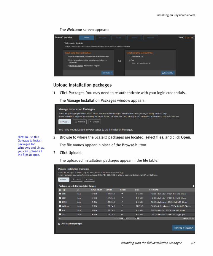
Installing on Physical Servers
The Welcome screen appears:
Upload installation packages
1. Click Packages. You may need to re-authenticate with your login credentials.
The Manage Installation Packages window appears:
Hint: To use this Gateway to install packages for Windows and Linux, you can upload all the files at once.
2. Browse to where the ScaleIO packages are located, select files, and click Open.
The file names appear in place of the Browse button.
3. Click Upload.
The uploaded installation packages appear in the file table.
Installing with the full Installation Manager 67

Installing on Physical Servers
4. Click Proceed to Install to proceed to the next step.
Note: To install the replication splitter for RecoverPoint, be sure to upload the splitter package.
The Provide Installation Topology screen appears:
Upload CSV file
If you have not created the CSV file yet, you can download a template by clicking Minimal or Complete on this screen.
1. Click Browse, browse to where the installation CSV file is located, select the file, and click Open.
2. For a new installation, select New installation. To update an existing installation, click the down-arrow and select Add to existing sys.
3. Click Upload Installation CSV.
68 EMC ScaleIO Installation Guide

Installing on Physical Servers
After successfully uploading the file, the Installation Configuration screen appears:
Initiate the installation
1. Enter and confirm a new MDM Password.
The MDM password is a new password that is configured for the MDM during the installation.
The MDM and LIA passwords must meet the following criteria:
• Between 6 and 31, ASCII-printable characters • Include at least 3 of the following groups: [a-z], [A-Z], [0-9], special chars
(!@#$ …)
Installing with the full Installation Manager 69

Installing on Physical Servers
• No white spaces
Note: When using the Installation Manager to extend (rather than to install) a system, enter the MDM IP address and the MDM password that you entered during the installation.
2. Enter and confirm the LIA password.
The LIA password is a new password that will be used to authenticate communication between the IM and the LIA.
Note: When using the Installation Manager to extend (rather than to install) a system, enter the LIA password that you entered during the installation.
3. Review, and accept, the end user license agreement.
ScaleIO installation enables unlimited use of the product, in non-production environments. To obtain a license for production use, and to receive technical support, open a service ticket with EMC Support at https://support.emc.com.
For complete information on licensing, see the EMC ScaleIO User Guide.
4. To use any of the following advanced options, select Set advanced options:
Option Description
Skip upload Don’t upload packages. You can use this if the packages were already uploaded.
Skip installation Don’t install packages. You can use this if the packages were already installed.
Skip configure Don’t configure ScaleIO components. You can use this if you only want to upload and install packages.
Skip LIA installation Don’t install the LIA on nodes.
Skip Linux devices validation Don’t validate Linux device names. For more information, see “Installing without validating Linux devices” on page 158.
70 EMC ScaleIO Installation Guide

Installing on Physical Servers
You can use the Installation Manager to configure Syslog event reporting and the Call Home feature. You can also configure these features after installation, via the CLI.
5. To configure Syslog reporting, select Configure MDM to send messages to syslog server, and enter the following parameters:
• Syslog ServerThe host name or IP address of the syslog server to where the messages are to be sent. Enter up to two servers, comma-separated.
• PortThe port of the syslog server (default 1468)
• Syslog FacilityThe facility level (default: Local0)
Hint: To skip the Call Home configuration, clear the Configure callhome selection. You can use the CLI to configure it later.
6. To configure the Call Home feature, enter the following parameters:
• SMTP ServerSMTP server that will send the Call Home messages
• SMTP CredentialsSMTP credentials, if necessary
• MDM CredentialsMDM credentials to be used by a new user, with a monitor role, that will be created for the purpose of Call Home functions
• Email fromThe email address that will be shown in the FROM field
• Email toThe email address where the messages are to be sent
• Customer nameName of the customer
• SeverityChoose the minimum event severity for call home messages
7. Review the displayed information, then click Start Installation.
8. Click the Monitor tab.
Complete the installation
The installation performs the following phases: query, upload, install, and configure. At the end of each phase, you need to approve moving to the next phase.
Installing with the full Installation Manager 71

Installing on Physical Servers
The monitor Install - query screen appears:
Hint: When adding nodes to an existing system, the query phase does expect to find currently-installed nodes.
The IM validates that there are no previously installed ScaleIO components on any of the requested installation nodes.
Note: When using the IM to install the replication splitter for RecoverPoint, this step is not performed on the SDC nodes.
You can change the display by selecting the following:
• Auto Refresh (default)• Hide Completed Successfully• Show All Phases
1. When this phase is completed, click Start upload phase.
72 EMC ScaleIO Installation Guide

Installing on Physical Servers
The monitor Install - upload screen appears:
This screen displays which ScaleIO packages are being uploaded to each server, and the status of each command.
When all commands are complete, a message, similar to the following, appears:
The installation process waits for your approval before moving on to the next stage.
2. Click Start install phase to proceed to the next stage.
Installing with the full Installation Manager 73

Installing on Physical Servers
The monitor Install - install screen appears:
3. When all Install commands rows are in Completed status, click Start configure phase.
The monitor Install - configure screen appears:
If you get an error message during the process, you can continue to the next phase, abort, or retry the installation.
74 EMC ScaleIO Installation Guide

Installing on Physical Servers
Note: If you proceed to the next stage, you will not be able to use the IM to retry failed tasks.
When all processes are finished, the following message appears:
Hint: Marking the operation completed signals to the IM that it can now be used for other installations, upgrades, etc.
4. Click Mark operation completed. The ScaleIO system installation is complete!
5. Install the GUI, as described in “Installing the ScaleIO GUI” on page 81.
To log in and use the GUI, see the EMC ScaleIO User Guide.
To enable the SNMP feature, see “Enabling and disabling Gateway components” on page 153.
Best practice suggestionFor optimal performance in environments with more than 60,000 IOPS, see the Fine-Tuning ScaleIO Performance Technical Notes.
Now that your ScaleIO system is up and running, the next task is to create volumes. The SDCs expose these volumes as local storage devices to the applications servers. For more information, see “SAN virtualization layer” on page 39.
You can create and map volumes using the ScaleIO CLI, as described in the EMC ScaleIO User Guide.
Installing with the Installation Manager wizardThis section describes how to use the installation wizard, the quickest way to get a ScaleIO system up and running.
Note: ScaleIO installation enables unlimited use of the product, in non-production environments. To obtain a license for production use, and to receive technical support, open a service ticket with EMC Support at https://support.emc.com.
For complete information on licensing, see the EMC ScaleIO User Guide.
Installing with the Installation Manager wizard 75

Installing on Physical Servers
The wizard is most suitable for environments when all servers are converged and in one Protection Domain.
Note: To use the wizard, you must prepare the Installation Manager, as described in “Preparing the Installation Manager and the Gateway” on page 52.
The wizard prepares all ScaleIO management and data communication on a single network. The IM must have access to that network to succeed. You can add additional data network IP addresses for SDS-SDS and SDS-SDC communication via the CLI or the GUI.
The wizard guides you through the following tasks:
◆ “Task 1: Setting up the installation” on page 76
◆ “Task 2: Running the installation” on page 79
Task 1: Setting up the installation
This section describes how to set up the wizard installation:
1. Log in to the Installation Manager (IM) server:
a. Point your browser to this URL: https://<IM_Server_IP>
where <IM_Server_IP> is the IP address of the server where you installed the IM package
b. Enter the default user name, admin, and the password defined when the IM was prepared, then click Login.
2. Upload installation packages:
a. From the Welcome screen, click Packages. You may need to re-authenticate.
b. From the Manage Installation Packages screen, browse to the extracted ScaleIO component packages, select the files, and click Open.
76 EMC ScaleIO Installation Guide

Installing on Physical Servers
c. Click Upload. The uploaded installation packages appear in the file table.
Click Proceed to Install.
3. In the Provide Installation Topology screen, click Installation wizard.
The Installation Configuration window appears:
Installing with the Installation Manager wizard 77

Installing on Physical Servers
Initiate the installation
4. Enter and confirm a new MDM Password and LIA Password.
The MDM and LIA passwords must meet the following criteria:
• Between 6 and 31, ASCII-printable characters • Include at least 3 of the following groups: [a-z], [A-Z], [0-9], special chars
(!@#$ …)• No white spaces
The Topology section is populated with three nodes: a Primary MDM, Secondary MDM, and Tie Breaker, the minimum necessary for a ScaleIO cluster. Each node is also defined as an SDS and an SDC.
5. Review, and accept, the end user license agreement.
ScaleIO installation enables unlimited use of the product, in non-production environments. To obtain a license for production use, and to receive technical support, open a service ticket with EMC Support at https://support.emc.com.
For complete information on licensing, see the EMC ScaleIO User Guide.
6. In the Topology section, enter server information:
Hint: To see the passwords, press Enter, then select Show passwords while editing.
a. For each node, change the IP address, select the host operating system, and enter the host password (for Linux, the password of the root user; for Windows, the password of the administrator user).
b. To add more hosts, click Clone host. The assigned IP is derived from the IP of the previous host.
Each cloned host is enabled to act as an SDS and an SDC.
7. Click Start Installation.
Note: A post-installation notice appears, that outlines the steps that are required after the wizard completes. The content of this notice will be repeated at the end of the process, or you can view it by clicking Post installation instructions from the Monitor screen.
78 EMC ScaleIO Installation Guide

Installing on Physical Servers
Task 2: Running the installation
The installation performs the following phases: query, upload, install, and configure. At the end of each phase, you need to approve moving to the next phase.
1. Click the Monitor tab. The monitor Install - query screen appears.
2. When this phase completes successfully, click Start upload phase.
Note: You can proceed, even if some of the tasks fail, then you can return later.
The monitor Install - upload screen shows which ScaleIO packages are being uploaded to each server.
When all commands are in a phase are complete, a message, similar to the following, appears:
The installation process waits for your approval before moving on to the next stage.
3. Click Start install phase to proceed to the next stage.
The monitor Install - install screen shows installation progress.
4. When all Install commands rows are in Completed status, click Start configure phase.
The monitor Install - configure screen shows configuration progress.
If you get an error message during the process, you can continue to the next phase, abort, or retry the installation.
Note: If you proceed to the next stage, you will not be able to use the IM to retry failed tasks.
Installing with the Installation Manager wizard 79

Installing on Physical Servers
When all processes are finished, the following message appears:
5. Click Mark operation completed. The ScaleIO system installation is complete!
The wizard installation creates one Protection Domain and one Storage Pool, both named default. These are used in the following section.
The post-installation notes appear, directing you to the steps necessary to start using your storage. These steps are described in the next section.
Enabling your storage
After the ScaleIO system is installed, follow these steps to enable using the storage. You must issue these commands from the Primary MDM, either directly, or via SSH/RDP.
Hint: You can also use the GUI to add SDS devices.
1. Add SDS devices, according to the following guidelines:
• You must add at least one device per SDS, to at least 3 SDSs, with a minimum of 100 GB free storage capacity per device.
• Balance the total device capacity over all SDSs.
a. Log in, by typing the following command:
Hint: If bash completion isn’t enabled, run ./etc/bash_completion/scli
scli --login --username <mdm_username> --password <mdm_password>
Note: On Windows-based MDMs, preface commands with cli, instead of scli.
b. Add devices, by typing the following command:
scli --add_sds_device --sds_ip <IP> --storage_pool_name default --device_path <device_path>
Example: For Linux: scli --add_sds_device --sds_ip 192.168.212.10 --storage_pool_name default --device_path /dev/sdX
80 EMC ScaleIO Installation Guide

Installing on Physical Servers
Note: Mapped volumes appear to the SDC as /dev/sciniX where X is a letter, starting from "a". For more information, see “Mounting ScaleIO” on page 187.
Example For Windows: cli --add_sds_device --sds_ip 192.168.212.10 --storage_pool_name default --device_path d
Note: For other options regarding adding Windows devices, see “Adding devices to SDS nodes on Windows servers” on page 155.
2. Add and map a volume:
a. Add a volume, by typing the following command:
scli --add_volume --storage_pool_name default --size_gb <SIZE> --volume_name <NAME>
Example: scli --add_volume --storage_pool_name default --size_gb 16 --volume_name vol01
b. Map a volume to an SDC, by typing the following command:
scli --map_volume_to_sdc --volume_name <NAME> --sdc_ip <IP>
Example: scli --map_volume_to_sdc --volume_name vol01 --sdc_ip 192.168.212.19
Now, you can start using your storage.
You can use the GUI or the CLI --query_all command to see the installed nodes and storage.
Installing the ScaleIO GUIThis section describes how to install the ScaleIO GUI. You can install the GUI on a Windows or Linux workstation.
Ensure that the workstation satisfies the minimum requirements, described in Table 1 on page 16.
Installing the ScaleIO GUI 81
Installing on Physical Servers
To install the GUI, run the following command:
◆ WindowsEMC-ScaleIO-gui-1.32-XXX.X.msi
◆ RHELrpm -U EMC-ScaleIO-gui-1.32-XXX.X.noarch.rpm
◆ Debiansudo dpkg -i EMC-ScaleIO-gui-1.32-XXX.X.deb
To log in and use the GUI, see the EMC ScaleIO User Guide.
Configuring the Installation ManagerThis section describes how to configure the following Installation Manager properties, by editing the gatewayUser.properties file.
◆ Enable Installation Manager (default: true)
To disable, set features.enable_IM=falseYou can completely disable the use of the IM’s default port, 443, by setting both this property and the features.enable_gateway property to false.
◆ Exclude RecoverPoint RPA nodes from being upgraded with the Installation Manager.
To exclude RPA nodes while upgrading with the Installation Manager, list the IP addresses to ignore on the im.ip.ignore.list line.
Example: im.ip.ignore.list=10.0.0.1,10.0.0.2,...
◆ Change default zero padding status (required for installing the replication splitter for RecoverPoint).
To enable zero padding, add the global.zero_padding=true parameter.
82 EMC ScaleIO Installation Guide

Installing on Physical Servers
To edit the properties, perform the following:
1. Use a text editor to open the gatewayUser.properties file, located in the following directory on the Installation Manager/Gateway server:
2. Edit the file with the desired changes.
3. Save and close the file.
4. Restart the scaleio-gateway service:
• Windows
Restart the EMC ScaleIO Gateway service
• Linux
Type the command service scaleio-gateway restart
Configuration is complete.
Gateway installed on Location of gatewayUser.properties file
Windows, 32-bit C:\Program Files (x86)\EMC\ScaleIO\Gateway\webapps\ROOT\WEB-INF\classes\
Windows, 64-bit C:\Program Files\EMC\ScaleIO\Gateway\webapps\ROOT\WEB-INF\classes\
Linux /opt/emc/scaleio/gateway/webapps/ROOT/WEB-INF/classes
Configuring the Installation Manager 83

Installing on Physical Servers
84 EMC ScaleIO Installation Guide
CHAPTER 4Installing on ESX Servers
This chapter describes how to install, deploy, and perform initial configuration of ScaleIO software components. Topics include:
◆ Before you begin .............................................................................................. 86◆ Deploying ScaleIO ............................................................................................ 89◆ Installing the ScaleIO GUI............................................................................... 112
ScaleIO provides you with automated tools to install and configure all ScaleIO components from one workstation, in both physical and virtual environments.
Note: ScaleIO installation enables unlimited use of the product, in non-production environments. To obtain a license for production use, and to receive technical support, open a service ticket with EMC Support at https://support.emc.com.
For complete information on licensing, see the EMC ScaleIO User Guide.
In VMware, you use the ScaleIO vSphere plug-in deployment wizard to install the MDM and SDS components on a dedicated ScaleIO virtual machine (SVM); whereas the SDC is installed directly on the ESX host.
As part of the installation process, it is highly recommended to install and configure the ScaleIO Lightweight Installation Agent (LIA). The LIA’s seamless communication enables future upgrades, the Get Info operation, as well as uninstalling. During initial installation, the IM establishes trust with the LIA, which facilitates its operation.
Hint: To make changes to the LIA configuration file, see Appendix D, “Troubleshooting and FAQ.”
You can limit the operations that LIA can perform by making changes to its configuration file.
The ScaleIO vSphere VMware deployment wizard enables you to perform all of these activities in a simple, efficient manner, over all the machines in a vCenter. The plug-in can also be used for provisioning ScaleIO nodes.
You can also use the deployment wizard with existing ScaleIO systems, to register them to vSphere, and to add SDS server nodes.
Installing on ESX Servers 85

Installing on ESX Servers
Note: It is highly recommended to use the deployment wizard for deployment and provisioning. If the need arises, you can perform these tasks manually, or in a combination with the wizard.
Before you beginThis section describes deployment prerequisites and other issues to consider before deploying ScaleIO.
Deployment prerequisites
Before you deploy ScaleIO, ensure compliance with the following prerequisites:
◆ The ESXi hosts must meet the hardware requirements listed in Table 1 on page 16.
◆ All ESX hosts selected to have either an MDM, Tie-Breaker, or SDS component installed on them, must have a defined local datastore, with a minimum of 10 GB free space (to be used for the SVM). If the ESX is only being used as an SDC, there is no need for this datastore.
◆ A minimum of three devices to be added to SDS, that all meet the following prerequisites:
• A minimum of 100 GB available storage capacity.• The devices must be free of partitions.• If a device has a datastore on it, before adding the device, you must either
remove the datastore, or use the plug-in Advanced settings option to enable VMDK creation.
• If the device has the ESXi operating system on it, you must use the plug-in Advanced settings option to enable VMDK creation.
◆ The host from which you run the PowerShell (.ps1) script must have the following prerequisites:
• Runs on Windows, with Java installed• PowerCLI from VMware (not Windows PowerShell) is installed • Has incoming and outgoing communication access to the vCenter
Note: If your vCenter runs on Windows OS, it is recommended to use it.
86 EMC ScaleIO Installation Guide

Installing on ESX Servers
◆ The vSphere web client (Virgo) server must have access to the host on which the PowerShell script will be used.
◆ The management network on all of the ESXs that are part of the ScaleIO system must have the following items configured:
• Virtual Machine Port Group (the name must be the same on all of the ESX hosts)
• When using distributed switches, the vDS must have the following items configured:
– VMKernel port (necessary only if using a single network)– dvPortGroup for virtual machines
◆ If using only a single network (management), you must manually configure the following:
• vSwitch• VMKernel Port• Virtual Machine Port Group
Before you begin 87

Installing on ESX Servers
• VMKernel Port Binding
Other deployment considerations
During deployment, you may need to address the following items:
◆ How are the ESX devices going to be added to the SVM:
• RDM (highly recommended)
Using RDM mapping, a device is created on the SVM that points to the physical disk on the ESX.
You can add RDM devices that are connected via RAID. If a local RDM is not connected via RAID, it may not be supported. To ensure the compatibility of these devices, you can add them as VMDK, or you can select Enable RDMs on non parallel SCSI controllers, as described in “Advanced settings options” on page 161. Enable this option before beginning the deployment.
Before enabling this feature, contact EMC Support.
• VMDK
A new datastore is created, with a VMDK, and the VMDK is added to the SVM. ScaleIO requires thick provisioning, so this process can take a long time.
In almost all cases, RDM is the preferred method to add physical device. Use the VMDK method only in the following scenarios:
– The physical device does not support RDM.
– The device already has a datastore, and the device isn’t being completely used. The excess area that is not already being used will be added as a ScaleIO device.
Note: To use VMDK, select Enable VMDK creation, as described in “Advanced settings options” on page 161.
◆ Are you deploying a very large system?
If you are deploying a very large ScaleIO system (several hundred nodes), you can increase the parallelism limit (default: 100), thus speeding up the deployment. This is dependent on the processing power of the vCenter.
To increase the parallelism limit, use the plug-in Advanced settings, as described in “Advanced settings options” on page 161.
88 EMC ScaleIO Installation Guide

Installing on ESX Servers
◆ Do you want to use separate networks for data and management (recommended), and which IP addresses will you use for the SVMs and VMkernels?
◆ Are there flash devices that will be added to the SDS?
◆ Do you want to create Fault Sets?
Deploying ScaleIOThis section describes how to deploy ScaleIO in the VMware environment. Deployment entails the following tasks:
◆ “Task 1: Registering the ScaleIO plug-in and uploading the OVA template” on page 89
◆ “Task 2: Accessing the plug-in” on page 92
◆ “Task 3: Installing the SDC on ESX hosts” on page 92
◆ “Task 4: Deploying ScaleIO” on page 94
Note: After deployment is complete, set all SVMs to start automatically with the system.
Task 1: Registering the ScaleIO plug-in and uploading the OVA template
This section describes how to use PowerCLI to register the ScaleIO plug-in on a vCenter and to upload the OVA template.
Note: To use your own web server, see “Manual registration of the ScaleIO plug-in” on page 162.
Before you begin, ensure that there is communication between the vSphere web client server (usually installed on the vCenter) and the web server storing the plug-in.
1. Copy the following files to your designated host (preferably your vCenter):
• ScaleIOVM_1.32.XXX.X.ova • EMC-ScaleIO-vSphere-plugin-installer-1.32-XXX.X.zip
2. Extract the contents of the zip file.
Deploying ScaleIO 89

Installing on ESX Servers
3. Using PowerCLI for VMware, set to Run as administrator, run Set-ExecutionPolicy AllSigned
4. From PowerCLI, run the following script: ScaleIOPluginSetup-1.32-XXX.X.ps1.
a. Enter the vCenter name or IP address, user name, and password.
Hint: You can also use this script to unregister a plug-in or to create an SVM template.
b. For Choose Mode, choose option 1, Register SIO plugin.
c. Read the upgrade notice, and enter y to continue.
d. For Select Registration Mode, choose Standard (simplified, using embedded Tomcat). This step may take a few minutes.
Note: You can use the Advanced option to install the plug-in using a ScaleIO Gateway from a previous installation or using your own web service. In either case, you must place this version’s plugin.zip file (EMC-ScaleIO-vSphere-web-plugin-1.32-XXX.X.zip) in your resources folder before running the installation. To use a previous ScaleIO Gateway, the resource folder is ScaleIO Gateway installation folder\webapps\root\resources.
e. If necessary, accept the thumbprint.
5. Log in to the vSphere web client. If you are already logged in, log out, then log in again.
6. In the PowerCLI window, press Enter to finish the plug-in download and return to the menu.
7. From the vSphere Home tab, verify that the ScaleIO icon is visible in the Inventories section.
Note: If the SIO icon is missing, the vSphere web client (Virgo) server failed to download/register the plug-in, due to one of the following reasons:
A connectivity problem (for example, network/firewall etc.) between the vSphere web client server and the web server storing the plug-in. Resolution: Verify that there is communication between the vSphere web client server and the web server that is storing the plug-in.
90 EMC ScaleIO Installation Guide

Installing on ESX Servers
URL problem. Resolution: Verify that the URL is https:// and is pointing to the correct web server IP address (i.e. ScaleIO Gateway).
For information on how to use the log to troubleshoot problems that may arise, see “Troubleshooting plug-in registration issues” on page 164.
To upload the OVA template, perform the following:
1. From the PowerCLI script, select 3 to Create SVM template.
2. Enter the parameters described in the following table (if you are already logged in, some of these parameters may not be necessary):
Hint: For best results, enter a local (not shared) datastore for each ESX server.
For faster, parallel, deployment in large-scale environments, you can use the OVA to create SVM templates on as many as eight datastores. To do so, enter the datastore names, and when you are done, leave the next line blank. The following example shows how to enter two datastores:
datastores[0]: datastore1datastores[1]: datastore1 (1)datastores[2]:
The upload procedure can take several minutes, during which time a temporary SVM is created, the templates are created, then the temporary SVM is deleted.
When each templates is created, a message, similar to the following, appears:
The template EMC ScaleIO SVM Template (v1.32.XXX.X) was successfully created.
Parameter Description
vcenter vCenter name or IP address
user name vCenter user name
password vCenter password
datacenter The name of the data center where the datastore that will store the template resides
ova_path The path of the SVM’s OVA
datastores A list of datastores, up to eight, on which the templates will be created. Press ENTER to stop specifying datastores.
Deploying ScaleIO 91

Installing on ESX Servers
3. When the process is complete, enter 4 to exit the plug-in script.
Task 2: Accessing the plug-in
This section describes how to access the plug-in from the vSphere Web Client home screen.
From the vSphere Web Client home tab, click .
The EMC ScaleIO screen appears.
Task 3: Installing the SDC on ESX hosts
This section describes how to install the SDC component on ESX hosts. This is a prerequisite for deploying a new ScaleIO system, and it must be applied to every ESX host that will be in the ScaleIO system, regardless of what role it is playing.
This process installs the SDC on the ESX host, after which you must restart the ESX host.
To install the SDC component , perform the following:
1. From the Basic tasks section of the EMC ScaleIO screen, click Install SDC on ESX.
92 EMC ScaleIO Installation Guide

Installing on ESX Servers
The Install SDC on ESX screen appears, showing all the ESX hosts on all the connected vCenters:
Hint: Entering the cluster password will automatically enter the same password for all servers in the cluster.
2. Select the ESX hosts, and enter the root password for each host.
Note: It is highly recommended to select all ESX hosts that might be included in an ESX system, even if only in the future.
3. Click Install. The status appears in the dialog.
4. When finished, click Finish.
5. Restart each ESX host.
Note: You must restart the ESX hosts before proceeding.
Proceed with the ScaleIO deployment.
Deploying ScaleIO 93

Installing on ESX Servers
Task 4: Deploying ScaleIO
This section describes how to use the deployment wizard to deploy ScaleIO in the VMware environment.
You can use the wizard to deploy ScaleIO from the beginning, or to register a ScaleIO system that has already been deployed, but not registered with vSphere.
To register an existing system, click Register ScaleIO system, and enter the credentials.
Before you begin, you may want to configure advanced installation options:
◆ Enable creation of VMDK◆ Enable RDMs on non-parallel SCSI controllers◆ Increase parallelism limit
These settings are accessed by clicking Advanced settings on the EMC ScaleIO screen. For more information, see “Other deployment considerations” on page 88.
To deploy a new system, perform the following:
1. From the Basic tasks section of the EMC ScaleIO screen, click Deploy ScaleIO environment.
The ScaleIO VMware Deployment Wizard begins. If you exited the previous deployment before completion, you will be able to return from where you left off.
The deployment wizard assumes that you are using the provided ScaleIO OVA template to create the ScaleIO virtual machines.
94 EMC ScaleIO Installation Guide

Installing on ESX Servers
The Select Installation type screen appears:
2. In the Select Installation screen, select from the following, then click Next:
◆ Create new ScaleIO systemCreate a new system
◆ Add servers to a registered ScaleIO systemAdd additional servers to a system that was created previously. Select the existing system from the drop-down list.
◆ Deploy ScaleIO Gateway for a registered ScaleIO systemDeploy a Gateway on a system that was created previously. Select the existing system from the drop-down list.
◆ Prepare environment without configuring ScaleIOSelect this option to use the wizard to prepare the environment without performing ScaleIO configuration (Protection Domains, Storage Pools, etc.).
3. If you selected Create a new ScaleIO system, review and agree to the license terms, then click Next.
Deploying ScaleIO 95

Installing on ESX Servers
If you selected Create a new ScaleIO system, the Create New System screen appears:
4. In the Create New System screen, enter the following, then click Next:
• System NameEnter a unique name for this system.
• Admin PasswordEnter, and confirm, a password for the ScaleIO admin user. The password must meet the listed criteria.
The Add ESX Hosts to Cluster screen appears.
96 EMC ScaleIO Installation Guide

Installing on ESX Servers
5. Select the vCenter on which to deploy the ScaleIO system.
The vCenter information is populated in the lower part of the screen.
6. Open the vCenter, select the ESX hosts to add to the ScaleIO system, then click Next.
Note: To configure ScaleIO, you must select a minimum of three ESX hosts. ESX hosts that do not have the SDC installed will not be available.
The Select Management Components screen appears:
7. In the Select Management Components screen, pair the ScaleIO management components with available ESX hosts, then click Next.
Deploying ScaleIO 97

Installing on ESX Servers
The Configure Call Home screen appears:
8. Configure the following settings (optional), then click Next:
• To configure Call home, select Configure Call Home, enter the email settings, enter the credentials to create a new read-only ScaleIO user, and select a minimum severity level for call home events.
• To configure syslog reporting, select Configure syslog, and enter the syslog server, port (default: 1468), and facility (default: 0).
• To configure DNS servers, enter their details.
98 EMC ScaleIO Installation Guide

Installing on ESX Servers
The Configure Protection Domains screen appears:
In the Configure Protection Domains screen, you can create (or remove) Protection Domains (PD). You must create at least one PD.
9. To create a PD, enter the following, then click Add:
• Protection Domain nameIt is recommended to use a meaningful name.
• RAM Read Cache size per SDSMinimum 128 MB
Added PDs appear in the lower section of the screen, together with existing PDs. You can remove a newly created PD by selecting it and clicking Remove.
10. Repeat to create additional PDs, then click Next.
Deploying ScaleIO 99

Installing on ESX Servers
The Configure Storage Pools screen appears:
In the Configure Storage Pools screen, you can create (or remove) Storage Pools (SP). You must create at least one SP.
11. To create a SP, configure the following, then click Add.
• Storage Pool nameIt is recommended to use meaningful names.
• Select to which PD to add the SP.
• To enable zero padding, select Enable zero padding. Zero padding must be enabled for use with RecoverPoint replication.
Added SPs appear in the lower section of the screen, inside the folder of the parent PD. You can remove a newly created SP by selecting it and clicking Remove.
12. Repeat to create additional SPs, then click Next.
100 EMC ScaleIO Installation Guide

Installing on ESX Servers
The Create Fault Sets screen appears:
You can use this screen to create Fault Sets (optional).
Note: When defining Fault Sets, you must follow the guidelines described in “Fault Sets” on page 26. Failure to do so may prevent creation of volumes.
13. To create a Fault Set, enter the name, select to which PD to add the Fault Set, then click Add. It is recommended to use meaningful names.
Added Fault Sets appear in the lower section of the screen, inside the folder of the parent PD. You can remove a newly created Fault Set by selecting it and clicking Remove.
14. Repeat to create additional Fault Sets (minimum of three), then click Next.
Deploying ScaleIO 101

Installing on ESX Servers
The Add SDSs screen appears:
Hint: To make the same selections for every ESX in a cluster, you can make your selections per cluster or datacenter.
15. Configure the following for every ESX host or SVM, then click Next:
• Whether it is acting as an SDS.
• If the SVM is an SDS, select a Protection Domain (required) and Fault Set (optional).
• If the SDS has flash devices, select Optimize for Flash to optimize ScaleIO efficiency for the flash devices.
102 EMC ScaleIO Installation Guide

Installing on ESX Servers
The Add devices to SDSs—Information tab appears:
When this screen appears, only the clusters are displayed.
Open the clusters, and select an ESX host.
From this screen, you can perform the following:
• Select devices (from the Select devices tab)Select storage devices to add to a single SDS.
• Support ... additional capacity per SDS without requiring a restartAllocate additional RAM for this future need
• Replicate selections (from the Replicate selections tab)Select devices for other SDSs, by replicating selections made in the Select devices tab. This can be very useful if your ESXs have identical attached devices.
Once you teach the deployment wizard what kind of selections you made for one SDS, the source, in the Select devices tab, you can use this option to easily select all of the same type of devices for other target SDSs. For example, if you select an SSD device for the source ESX, and then replicate this selection to the targets, the deployment wizard can automatically select all other SSD devices on the target SDSs.
Deploying ScaleIO 103

Installing on ESX Servers
Note: Device matching is performed based on the device runtime name.
To replicate device selections, all of the following conditions must be met:
– The number of devices on each ESX must be identical.
– Source and target devices must be identical in the following ways: a) both are SSD or non-SSD, b) both have datastores on them or do not, c) both are roughly the same size (within 20%), and d) both are connected via a RAID controller or directly attached.
– At least one of the following conditions must be met: a) both SDSs are in the same Protection Domain, b) both SDSs are in different Protection Domains, but with the same list of Storage Pools, or c) the target SDS is in a Protection Domain with only one Storage Pool.
16. Click Select devices.
The Select devices tab appears:
This screen shows the devices whose free space can be added to the selected ESX host/SDS. Youshould balance the capacity over the selected SDS.
17. To add a device’s space to an SDS, select the device’s Add Device box and choose a Storage Pool.
104 EMC ScaleIO Installation Guide

Installing on ESX Servers
Note: If you selected to create VMDK (before the deployment), the following options appear: —Create VMDK box. Select this for all relevant devices.—Select all available devices. Click this to select all devices with a VMFS, and with unused capacity that can be added to the ScaleIO system.
18. To replicate selections to other SDSs, perform the following:
a. Select the Replicate selection tab.
b. Select the ESX whose device selection you wish to replicate. This is the source ESX.
c. Select the targetESXs to which to replicate the selection of the source ESX.
d. Click Copy configuration.
The results are displayed in the right pane of the screen.
19. When you have selected devices for all SDSs, click Next.
Note: You must select at least one device for each SDS.
Deploying ScaleIO 105

Installing on ESX Servers
The Add SDCs screen appears:
20. Enter the SDC settings, as follows:
a. For each ESX to be added as an SDC, perform the following:
1. Select the SDC check box.Hint: To show the entered ESX passwords, select Show passwords.
2. Type the ESX root password.
b. Choose whether to enable or disable the LUN comparison for ESX hosts. In general, in environments where the SDC is installed on ESX and also on Windows/Linux hosts, you should set this to Disabled.
Note: Before enablingLUN comparison, consult your environment administrator.
c. Click Next to continue.
106 EMC ScaleIO Installation Guide

Installing on ESX Servers
The Configure Upgrade Components dialog appears:
21. Configure the ScaleIO Gateway, by performing the following::
a. Select an ESX to host the Gateway virtual machine. A unique SVM will be created for the Gateway.
b. Enter and confirm a password for the Gateway admin user.
22. Configure the Lightweight Installation Agent (LIA) on the SVMs:
a. Enter and confirm a password for the LIA. The password must be the same across all SVMs in the system.
b. Click Next.
Note: You can only move forward if the passwords meet the listed criteria, and if the confirmation passwords match the entered passwords.
Deploying ScaleIO 107

Installing on ESX Servers
The Select OVA Template screen appears:
23. In the Select OVA Template screen, perform the following, then click Next:
a. Select the template to use to create the ScaleIO virtual machines (SVM). The default is EMC ScaleIO SVM Template. If you uploaded a template to multiple datastores, you can select them all, for faster deployment.
Note: If you select a custom template, ensure that it is compatible with the VMware plug-in and the ScaleIO MDM.
b. Enter and confirm a new root password, that will be used for all SVMs to be created.
The Configure Networks screen appears:
In the Configure Networks screen, you choose to use either a single network for management and data transfer, or to use separate networks. Separating the networks is recommended for security and increased efficiency. You can select one data network or two.
108 EMC ScaleIO Installation Guide

Installing on ESX Servers
The management network, used to connect and manage the SVMs, is normally connected to the client management network, a 1 GB network.
The data network is internal, enabling communication between the ScaleIO components, and is generally a 10GB network.
Note: The selected networks must have communication with all of the system nodes. In some cases, while the wizard does verify that the network names match, this does not guarantee communication, as the VLAN IDs may have been manually altered.
24. Enter the following information:
• To use one network, select a management network, then proceed to step 25 .
Hint: For best results, it is highly recommended to use the plug-in to create the data networks, as opposed to creating them manually.
• To use separate networks, select a management network label and one or two data network labels. If the data network already exists, select it from the drop-down box. Otherwise, configure the data network by clicking Create new network.
The Create New Data Network screen appears:
In the Create New Data Network screen, enter the following information:
– Network nameThe name of the VMware network
Deploying ScaleIO 109

Installing on ESX Servers
– VMkernel nameThe name of the VMkernel (used to support multipathing)
– VLAN IDNetwork ID
Hint: You can click
to auto-fill the
values for Data NIC
and VMkernel IP.
– For each listed ESX, select a Data NIC, a VMkernel IP, and a VmKernel Subnet Mask.
• Click OK. The data network is created.
The wizard will automatically configure the following for the data network:
– vSwitch– VMkernel Port– Virtual Machine Port Group– VMkernel Port Binding
25. Click Next.
The Configure SVM screen appears:
Note: This screen will look slightly different if you chose to use multiple networks.
Hint: You can click
to auto-fill the
values for IP.
26. For each SVM, perform the following, then click Next:
a. Enter the IP address, Subnet mask, and Default Gateway.
SVMs that are members of the MDM cluster are indicated by .
110 EMC ScaleIO Installation Guide

Installing on ESX Servers
b. You can select a datastore, or allow automatic selection.
The Review Summary screen appears.
27. Review the configuration. Click Finish to begin deployment or Back to make changes.
28. Enter the vCenter user name and password, then click OK, to begin the deployment.
The Deployment Progress screen appears:
During the deployment process you can view progress, pause the deployment, and view logs.
To pause the deployment, click Pause. Steps that are already in progress will pause after they complete.
After pausing, you can do the following:
• Continue—Click Continue deployment.
• Abort—Click Abort.
• Roll back all deployment activities—Click Cancel and Rollback. Rollback cannot be canceled once started.
Deploying ScaleIO 111

Installing on ESX Servers
• Roll back failed tasks only—Click Rollback failed tasks. Rollback cannot be canceled once started.
29. When the deployment is complete, click Finish.
If a task failed, click Continue deployment to try again.
30. After deployment is complete, ql bk^_ib ^rqlpq^oq) mbocloj qeb cliiltfkd7
a. Click the ESX Configuration tab.
b. From the Software section, click Virtual Machine Startup/Shutdown.
c. Click Properties...
d. In the dialog box, select Allow virtual machines to start and stop automatically with the system.
b. Click OK.
c. Repeat this process for all BPU elpqp.
Where to go from hereNow that your ScaleIO system is up and running, the next task is to create volumes. For more information, see the EMC ScaleIO User Guide.
Installing the ScaleIO GUIThis section describes how to install the ScaleIO GUI. You can install the GUI on a Windows or Linux workstation.
Ensure that the workstation satisfies the minimum requirements, described in Table 1 on page 16.
To install the GUI, run the following command:
◆ WindowsEMC-ScaleIO-gui-1.32-XXX.X.msi
◆ RHELrpm -U EMC-ScaleIO-gui-1.32-XXX.X.noarch.rpm
◆ Debiansudo dpkg -i EMC-ScaleIO-gui-1.32-XXX.X.deb
112 EMC ScaleIO Installation Guide

PART 3
Reference
The chapters in this part of the guide supply additional information on advanced reference topics. Chapters include:
Appendix A, “Manual Installation”
This chapter describes how to deploy ScaleIO without the automated tools, shows a simple set up, and how to uninstall manually.
Appendix B, “Advanced Topics”
This chapter describes advanced topics related to installation.
Appendix C, “Upgrading and Maintaining”
This chapter describes how to upgrade and maintain ScaleIO components.
Appendix D, “Troubleshooting and FAQ”
This chapter describes how to settle issues that may arise relating to the installation process.
“Glossary”


APPENDIX AManual Installation
This appendix describes how to install ScaleIO components in situations when the Installation Manager and VMware deployment wizard are not suitable. Topics include:
◆ Manual installation on physical servers.......................................................... 115◆ Quick installation and provisioning example .................................................. 124◆ Configuring spare capacity ............................................................................. 127◆ Manually upgrading ScaleIO components....................................................... 133
This appendix is for reference purposes only. It is highly recommended to install ScaleIO with the Installation Manager or the VMware deployment wizard. If that is not possible, contact EMC Support.
Manual installation on physical serversThis section describes how to install ScaleIO manually on Linux and Windows physical servers.
Note: ScaleIO installation enables unlimited use of the product, in non-production environments. To obtain a license for production use, and to receive technical support, open a service ticket with EMC Support at https://support.emc.com.
For complete information on licensing, see the EMC ScaleIO User Guide.
To install ScaleIO manually, you must install the following components:
◆ MDM
You can install MDM in Cluster mode (using a primary, secondary, and tie-breaker MDM on three separate servers) or in Single mode (a single MDM on one server).
Manual Installation 115

Manual Installation
It is not recommended to use Single Mode in production systems, except in temporary situations. The MDM contains all the metadata required for system operation. Single Mode has no protection, and exposes the system to a single point of failure.
◆ Tie-Breaker
The Tie-Breaker is installed on a third server, and is required when using MDM cluster mode.
◆ Call-Home (optional)
The Call-Home function emails status information to the ScaleIO support center and the local ScaleIO administrator. Call-Home is installed on the same server where MDM is installed, and only after the MDM was installed.
For the Call-Home feature to function, you must configure the SMTP system on the MDM servers to enable ScaleIO to send outgoing emails.
◆ SDS
The SDS is installed on all servers that will contribute storage devices to the ScaleIO system.
◆ SDC
The SDC is installed on every server that will expose ScaleIO volumes to the application running on it.
◆ LIA (highly recommended, non-mandatory)
It is highly recommended to install the Lightweight Installation Agent (LIA) on every node in the ScaleIO system. This will enable upgrade, uninstall, and Get Info operations to be performed automatically using the Installation Manager. In a manual installation, if you decide to configure LIA and use it later, and for some reason you want to distribute LIA yourself, you also need to set the installation ID in this file: /opt/emc/scaleio/lia/cfg/installation_id.txt. Set it to the install ID that returns from the query_license CLI command.
You can install ScaleIO components on Linux and Windows machines. Proceed to the section that matches your environment:
◆ “Installing on Linux servers” on page 117
◆ “Installing on Windows servers” on page 121
116 EMC ScaleIO Installation Guide

Manual Installation
Installing on Linux servers
This section describes how to perform a manual installation of the ScaleIO components on Linux servers. It is highly recommended to use the automated Installation Manager as described in “Preparing the Installation Manager and the Gateway” on page 52.
Before installing, ensure that your servers meet the requirements listed in Table 1 on page 16.
Note: If you intend to use the replication feature via RecoverPoint on RHEL 6.x servers, refer to the EMC ScaleIO Write Splitter for RecoverPoint Technical Notes before beginning the installation.
To install ScaleIO components, perform the following:
1. Extract and import the key:
a. Extract from either:
– a LIA installation: /opt/emc/scaleio/lia/cfg/GPG/RPM-GPG-KEY-ScaleIO
– the IM itself: c:\Program Files\EMC\ScaleIO\Gateway\conf\RPM-GPG-KEY-ScaleIO
b. Import the key: rpm --import RPM-GPG-KEY-ScaleIO
2. Install the MDM components:
a. For both cluster and single mode, run the following command, from the node which is to act as MDM:
rpm -i <full rpm file path>
For example:
rpm -i EMC-ScaleIO-mdm-1.32-XXX.X.el6.x86_64.rpm
For single mode installation, the MDM installation is complete. Proceed with the Call-Home component.
b. For cluster mode, continue here:
1. Install the second MDM by repeating the previous step on a different server.
Manual installation on physical servers 117

Manual Installation
2. On a third server, install the Tie-Breaker, by running the following command
rpm -i <full rpm file path>
For example:
rpm -i EMC-ScaleIO-tb-1.32-XXX.X.el6.x86_64.rpm
Note: The default MDM credentials are:
user name: adminpassword: admin
3. Install the Call-Home component (optional), by running the following command, on each MDM node:
rpm -i <full rpm file path>
For example:
rpm -i EMC-ScaleIO-callhome-1.32-XXX.X.el6.x86_64.rpm
The Call-Home component requires further configuration, as described in “Configuring the Call-Home feature” on page 120.
4. Install the SDS component on every server that will contribute storage drives to the ScaleIO system, by running the following command:
rpm –i <full rpm file path>
For example:
rpm –i EMC-ScaleIO-sds-1.32-XXX.X.el6.x86_64.rpm
Note: When using fast devices (SSD), you can optimize SDS parameters by replacing the previous command with the following:
CONF=IOPS rpm -i EMC-ScaleIO-sds-1.32-XXX.X.el6.x86_64.rpm
5. Install the SDC component on every server that will expose ScaleIO volumes to the application running on it, by running the following command:
MDM_IP=<IP of the MDM> rpm –i <full rpm file path>
118 EMC ScaleIO Installation Guide

Manual Installation
For example:
MDM_IP=192.168.1.4,192.168.1.5 rpm -i EMC-ScaleIO-sdc-1.32-XXX.X.el6.x86_64.rpm
Note: Add all the MDM IP addresses (minimally, one primary and one secondary address).
6. Install the LIA component on every node (optional), by running the following command:
Token=<password> rpm -i <full rpm file path>
The password must meet the following criteria:
• Between 6 and 31, ASCII-printable characters • No blank spaces• Include at least 3 of the following groups: [a-z], [A-Z], [0-9], special chars
(!@#$ …)
For example:
Token=Scaleio123 rpm -i EMC-ScaleIO-lia-1.32-XXX.X.el6.x86_64.rpm
The LIA component requires security configuration, as described in the EMC ScaleIO Security Configuration Guide.
Post-installation considerationsEach installed component creates subdirectories for its use in the following directory:
/opt/emc/scaleio/<component>/
For example: /opt/emc/scaleio/mdm/
1. Install the GUI, where needed, by running the following command:
• Linux
rpm -i <RPM_GUI_package_name>
• Ubuntu (run the command with administrator privileges)
dpkg -i <DEB_GUI_package_name>
Manual installation on physical servers 119

Manual Installation
2. To install the ScaleIO Gateway, follow the instructions described in “Preparing the Installation Manager and the Gateway” on page 52.
The ScaleIO Gateway includes the REST Gateway, the Installation Manager (IM), and the SNMP trap sender functionality.
After installing, you need to create the MDM cluster and provision storage. See “Quick installation and provisioning example” on page 124 for an example.
Note: For optimal performance in environments with more than 60,000 IOPS, see the Fine-Tuning ScaleIO Performance Technical Notes.
Configuring the Call-Home featureThis section describes the additional configuration required to enable the Call-Home feature.
To configure, perform the following:
1. Edit the conf.txt file for your operating system, according to the parameters in the following table:
• WindowsC:\Program Files\EMC\ScaleIO\callhome\cfg
• Linux/opt/emc/scaleio/callhome/cfg
Table 6 Call-Home configuration parameters
Section Parameter Description
[general] email_from User's source email address to be listed in all outgoing mails
username MDM user that Call-Home home uses to connect to the MDM and perform the queries. Recommended to be a user with monitor role.
password Password for the user name specified in previous section
customer_name The customer name. This will enable support to assist more rapidly.
120 EMC ScaleIO Installation Guide

Manual Installation
2. Restart the CallHome service.
Installing on Windows servers
This section describes how to perform a manual installation of the ScaleIO components on Windows servers. It is highly recommended to use the automated Installation Manager as described in “Preparing the Installation Manager and the Gateway” on page 52.
Before installing, ensure that your servers meet the requirements listed in Table 1 on page 16.
To install ScaleIO components, perform the following:
1. Install the MDM components:
a. Install PythonModulesInstall.exe on all nodes that will run the MDM. Download the file from EMC Online Support (https://support.emc.com).
b. For both cluster and single mode, run the following file:
EMC-ScaleIO-mdm-1.32.XXX.X.msi
For single mode installation, the MDM installation is complete. Proceed with the Call-Home component.
c. For cluster mode, continue here:
1. Install the second MDM by repeating the previous steps on a different server.
2. On a third server, install the Tie-Breaker, by running the following file:
[smtp] host SMTP server host name or IP
username SMTP server credentials
password SMTP server credentials
[email_alert] email_to Customer destination email address that should receive alert mails regarding ScaleIO events
severity Event severity threshold at which Call-Home will start sending alert mails, either Warning, Error (default), or Critical.
Table 6 Call-Home configuration parameters
Section Parameter Description
Manual installation on physical servers 121

Manual Installation
EMC-ScaleIO-tb-1.32.XXX.X.msi
Note: The default MDM credentials are:
user name: adminpassword: admin
2. Install the Call-Home component (optional), by running the following file on the MDM nodes:
EMC-ScaleIO-callhome-1.32.XXX.X.msi
Note: Call-Home must be installed after the MDM is installed.
The Call-Home component requires further configuration, as described in “Configuring the Call-Home feature” on page 120.
3. Install the SDS component on every server that will contribute storage drives to the ScaleIO system, by running the following file:
EMC-ScaleIO-sds-1.32.XXX.X.msi
Note: When using fast devices (SSD), you can optimize SDS parameters by replacing the previous command with the following:
msiexec /i EMC-ScaleIO-sds-1.32-XXX.X.msi CONF=IOPS
4. Install the SDC component on every server that will expose ScaleIO volumes to the application running on it, by running the following file:
msiexec /i EMC-ScaleIO-sdc-1.32.XXX.X.msi MDM_IP=<MDM_IP>
Use the IP address of the MDM.
5. Install the LIA component on every node (optional), by running the following command:
msiexec /i EMC-ScaleIO-lia-1.32.XXX.X.msi TOKEN=<password>
The password must meet the following criteria:
• Between 6 and 31, ASCII-printable characters • No blank spaces
122 EMC ScaleIO Installation Guide

Manual Installation
• Include at least 3 of the following groups: [a-z], [A-Z], [0-9], special chars (!@#$ …)
The LIA component requires security configuration, as described in the EMC ScaleIO Security Configuration Guide.
Post-installation considerationsEach installed component creates subdirectories for its use in the following directory:
c:\Program files\emc\scaleio\<component>\
For example: c:\Program files\emc\scaleio\mdm\
1. Install the GUI, where needed, by running the following command:
EMC-ScaleIO-gui-1.32-XXX.X.msi
2. To install the ScaleIO Gateway, follow the instructions described in “Preparing the Installation Manager and the Gateway” on page 52.
The ScaleIO Gateway includes the REST Gateway, the Installation Manager (IM), and the SNMP trap sender functionality.
Note: For optimal performance in environments with more than 60,000 IOPS, see the Fine-Tuning ScaleIO Performance Technical Notes.
Manual installation on physical servers 123

Manual Installation
Quick installation and provisioning exampleThis section illustrates a quick and simple manual installation.
The flow in the example below shows how to install and configure ScaleIO in the following configuration:
◆ MDM resides on nodes IP1 and IP2
◆ The Tie-Breaker is installed on node IP3.
◆ SDSs are installed on all nodes. Each has two physical devices dedicated for ScaleIO: /dev/d1 and /dev/d2.
◆ SDC is installed on node IP1.
◆ Protection Domain name is ScaleIO-1
◆ Storage Pool name is sp1
◆ Call-home and LIA are not being installed in this example.
Installing ScaleIO componentsThis section describes how to install the required components on a Linux server. In a Windows environment, use commands that are relevant to MSI files.
1. Install the MDMs on nodes IP1 and IP2, by running the following command on those nodes:
rpm -i EMC-ScaleIO-mdm-1.32-XXX.X.el6.x86_64.rpm
124 EMC ScaleIO Installation Guide

Manual Installation
2. Install the Tie-Breaker on node IP3, by running the following command on that node:
rpm -i EMC-ScaleIO-tb-1.32-XXX.X.el6.x86_64.rpm
3. Install the SDS on all nodes (IP1, IP2, and IP3), by running the following command on all nodes:
rpm –i EMC-ScaleIO-sds-1.32-XXX.X.el6.x86_64.rpm
4. Install the SDC on node IP1, by running the following command on that node:
MDM_IP=IP1 rpm –i EMC-ScaleIO-sdc-1.32.XXX.X.el6.x86_64.rpm
Preparing the MDMThis section describes how to prepare the MDM.
Hint: In a Windows environment, ScaleIO CLI commands are prefaced with cli, instead of scli.
1. Define the Primary MDM on node IP1, and add both management IP addresses, by running the following command, from a node on which the MDM is installed:
scli --add_primary_mdm --primary_mdm_ip IP1 --mdm_management_ip IP1,IP2
2. Log in with default administrator credentials (admin admin), change password, and log in with new password, by running the following commands:
scli --login --mdm_ip IP1 --username admin --password admin
scli --set_password --mdm_ip IP1 --old_password admin --new_password <password>
scli --login --mdm_ip IP1 --username admin --password <password>
3. If you are installing a ScaleIO license, do so by running the following command:
scli --set_license --mdm_ip IP1 --license_file <full_path_to_license_file>
Note: ScaleIO installation enables unlimited use of the product, in non-production environments. To obtain a license for production use, and to receive technical support, open a service ticket with EMC Support at
Quick installation and provisioning example 125

Manual Installation
https://support.emc.com.
For complete information on licensing, see the EMC ScaleIO User Guide.
4. Define the Secondary MDM on node IP2, by running the following command:
scli --add_secondary_mdm --mdm_ip IP1 --secondary_mdm_ip IP2
5. Define the Tie-Breaker on node IP3, by running the following command:
scli --add_tb --tb_ip IP3 --mdm_ip IP1,IP2
6. Switch to cluster mode, by running the following command:
scli --switch_to_cluster_mode --mdm_ip IP1,IP2
Adding capacityThis section describes how to add capacity.
1. Define a Protection Domain, ScaleIO-1, by running the following command:
scli --add_protection_domain --mdm_ip IP1,IP2 --protection_domain_name ScaleIO-1
2. Add a Storage Pool, sp1, by running the following command:
scli --add_storage_pool --mdm_ip IP1,IP2 --protection_domain_name ScaleIO-1 --storage_pool_name sp1
3. Add an SDS on IP1, and its devices to ScaleIO-1, and name it sds1, by running the following command:
scli --add_sds --mdm_ip IP1,IP2 --sds_ip IP1--device_path /dev/d1,/dev/d2 --sds_name sds1 --protection_domain_name ScaleIO-1--storage_pool_name sp1
Note: To add devices on a Windows-based SDS, you can use either a drive letter or a file for the SDS. For more information, see “Adding devices to SDS nodes on Windows servers” on page 155.
126 EMC ScaleIO Installation Guide

Manual Installation
4. Add an SDS on IP2, and its devices to ScaleIO-1, add meaningful names to the devices (optional), and name the SDS sds2, by running the following command:
scli --add_sds --mdm_ip IP1,IP2 --sds_ip IP2--device_path /dev/d1,/dev/d2 --device_name node_12_dev1,node_12_dev5--sds_name sds2--protection_domain_name ScaleIO-1--storage_pool_name sp1
5. Add an SDS on IP3, and its devices to ScaleIO-1, and name it sds3, by running the following command:
scli --add_sds --mdm_ip IP1,IP2 --sds_ip IP3--device_path /dev/d1,/dev/d2 --sds_name sds3--protection_domain_name ScaleIO-1--storage_pool_name sp1
Creating and mapping volumesThis section describes how to create and map volumes.
1. Define a 2500 GB volume, and name it Vol1, by running the following command:
scli --add_volume --mdm_ip IP1,IP2 --size_gb 2500 --volume_name vol1 --protection_domain_name ScaleIO-1--storage_pool_name sp1
2. Map Vol1 to the SDC on IP1, by running the following command:
scli --map_volume_to_sdc --mdm_ip IP1,IP2 --volume_name vol1 --sdc_ip IP1
Configuring spare capacityThis section describes how to configure spare capacity for your system. This step is highly recommended in any system with less than 10 SDSs or Fault Sets.
Modify the spare capacity, by running the following command:
modify_spare_policy --protection_domain_name ScaleIO-1 --storage_pool_name sp1 --spare_percentage 34 [--i_am_sure]
Quick installation and provisioning example 127

Manual Installation
The number 34 represents the percentage of total capacity set aside to ensure data integrity during server failures. The percentage is derived by 1/(number of SDS), which yields the recommended percentage for less than 10 balanced servers.
For more information, see “Modifying spare policy” in the EMC ScaleIO User Guide.
Deploying ScaleIO on ESXThis section describes topics related to installing ScaleIO in VMware environments.
It is highly recommended to deploy using the VMware plug-in deployment wizard. This appendix describes tasks that are necessary in cases where this is not possible or desirable, such as for scripting. Topics include:
◆ Deploying the ScaleIO virtual machine (SVM) ................................................. 128◆ Configuring the UUID on virtual machines....................................................... 130◆ Installing the SDC directly on an ESX host....................................................... 131◆ Optimizing the guest operating system performance ...................................... 132
Before starting, obtain the IP addresses for all of the nodes to be installed, and an additional IP address for the MDM cluster, as described in the following table:
Task 1: Deploying the ScaleIO virtual machine (SVM)
This section describes how to deploy the SVM and prepare it for installation of ScaleIO. This is necessary when the SDC installed on ESX, but all other components are installed on ScaleIO virtual machines (SVM).
Note: Before deploying, ensure that networks for each ESX to be part of the system have a properly defined Port Group and VMkernel.
Number of networks IP addresses required
1 network (management network)
• 1 for vmnic• 1 for SVM
2 networks • 2 for vmnic (1 for mgmt, 1 for data)• 2 for SVM (1 for mgmt, 1 for data)
3 networks • 3 for vmnic (1 for mgmt, 2 for data)• 3 for SVM (1 for mgmt, 2 for data)
128 EMC ScaleIO Installation Guide

Manual Installation
To deploy the SVM on the ESX, perform the following:
1. Download the installation software from the EMC Support site (https://support.emc.com). If necessary, extract the files to an installation folder.
2. Download the following document: http://www.vmware.com/files/pdf/techpaper/vmware-multipathing-configuration-software-iSCSI-port-binding.pdf.
3. Use the vSphere client to connect to a vCenter.
4. Select File > Deploy OVF Template.
The Deploy OVF Template wizard appears.
5. Enter the full path to the OVA, and click Next.
6. Accept all default values, and click Finish.
7. Clone the SVM to each ESX host.
8. On each ESX physical host, configure the network and NTP (and DNS, if necessary).
a. Using the console, start the SVM, and login. The default user name is root, and the default password is admin.
Deploying ScaleIO on ESX 129

Manual Installation
b. Configure the network:
– IP address– Gateway address– DNS– NTP server
Hint: When using the OVA, the installation packages can be found in /root/install/.
9. On each SVM in the system, install the relevant ScaleIO components, as described in “Installing on Linux servers” on page 117. The packages are located under /root/install
Task 2: Configuring the UUID on virtual machines
To configure the virtual machine, you must enable the UUID attribute on every virtual machine, by performing the following:
1. Start the vSphere Client, and log in to a vCenter Server.
2. Select Virtual Machines and Templates.
3. From the Virtual Machines tab, right-click the virtual machine, and choose Power > Power Off.
The virtual machine powers off.
4. Right-click the virtual machine, and click Edit Settings.
5. From the Options tab, select Advanced > General in the settings column.
6. Click Configuration Parameters.
The Configuration Parameters window appears.
7. Click Add Row, and enter the following:
• In the Name column, enter disk.EnableUUID.• In the Value column, enter TRUE.
8. Click OK.
9. Power on the virtual machine.
10. Repeat this procedure for every SVM in the ScaleIO system.
130 EMC ScaleIO Installation Guide

Manual Installation
Task 3: Installing the SDC directly on an ESX host
This section describes how to install the SDC directly on an ESXi host.
To install the SDC component on an ESXi host, perform the following:
1. Set the acceptance level of your host to PartnerSupported, by typing:
esxcli software acceptance set --level=PartnerSupported
2. Install the SDC VIB, by typing the following:
Hint: To install without changing the acceptance level, type this command: esxcli software vib install -f -d <VIB location>
esxcli software vib install -d <full_path_to_VIB>
where full_path_to_VIB is the full path to the sdc-1.32.XXX.X-esx5.5.zip file
3. Reboot the ESX host. The SDC will not automatically boot up at this point.
You need to update the SDC GUID and MDM IP address parameters:
• GUID, for example: 12345678-90AB-CDEF-1234-567890ABCDEF
• MDM IP addresses. You can define multiple MDM clusters, each with multiple IP addresses.
– Separate the IP addresses of the same MDM cluster with a “,” symbol.
– Separate multiple MDM clusters with the “+” symbol.
In the following example, there are two MDM clusters, the first has two IP addresses and the second has only one:
10.20.30.40,50.60.70.80+11.22.33.44
4. To update the SDC parameters, type the following command:
esxcli system module parameters set -m scini -p "IoctlIniGuidStr=<GUID> IoctlMdmIPStr=<MDM_IPs>"
where:
• GUID is the GUID (maximum of 1024 digits)
• MDM_IPs is the IP addresses, as described earlier
5. Back up the parameters, by typing the following:
/bin/auto-backup.sh
6. Load the SDC module, by typing the following:
Deploying ScaleIO on ESX 131

Manual Installation
esxcli system module load -m scini
Task 4: Optimizing the guest operating system performance
The configuration of the guest operating system affects the performance of the system. To modify the guests' configuration for optimal ScaleIO usage, perform the following procedures.
Modify the device scheduler (Linux guests only)The following command modifies the I/O scheduler of the devices. Perform the following command for each device which exposes a ScaleIO volume inside the guest virtual machine.
Command
echo noop > /sys/block/<device_name>/queue/scheduler
Example
echo noop > /sys/block/sds/queue/scheduler
Modify the SCSI controller type of the guest virtual machineTo configure the SCSI controller type to use a Paravirtual SCSI (PVSCSI) adapter, perform the following steps for each guest using ScaleIO storage.
Note: Before performing the following steps, consult VMware documentation to verify that your guest operating system supports Paravirtual SCSI adapters.
1. Power off the guest virtual machine.
2. Open the vSphere client, and right click on the guest.
3. Select Edit Settings.
4. Select SCSI Controller 0.
5. Click Change Type.
6. Select VMware Paravirtual.
7. Click OK.
132 EMC ScaleIO Installation Guide

Manual Installation
Manually upgrading ScaleIO componentsThis section describes how to manually upgrade ScaleIO components from v1.3x to a newer version.
To manually upgrade components from previous versions, contact EMC Support.
Note: It is highly recommended to use the Installation Manager to upgrade ScaleIO components, as described in “Upgrading from a previous version” on page 165.
Before you begin
Before you begin, use the GUI to verify that the system is error-free and is not currently in rebuild or rebalance states. Do not attempt to upgrade the system if there are errors or a rebuild\rebalance in progress. Rectify all issues and wait until the rebuild\rebalance is complete before you begin the upgrade procedure. Ensure that you know the IP addresses of the Primary and Secondary MDMs in your system. They are required for the purposes of switching system control during the upgrade procedure.
1. Start the ScaleIO GUI and verify that:
• No rebuild or rebalance is running in the background
• No degraded capacity exists
• No SDS or SDC is disconnected
• No SDS device is in error state
• The MDM cluster is not in degraded mode, including the Tie-Breaker
Proceed to the section that matches your operating environment:
◆ “Upgrading Windows systems” on page 133
◆ “Upgrading Linux systems” on page 138
◆ “Upgrading VMware systems” on page 142
Upgrading Windows systems
This section describes how to manually upgrade ScaleIO components on Microsoft
Manually upgrading ScaleIO components 133

Manual Installation
Windows 2012 R2 systems. In general, the upgrade procedure includes the following activities, in chronological order:
1. Verify that system status is error-free, and that no rebuilding or rebalancing is in progress, as described in “Before you begin” on page 133.
2. Identify MDM node addresses, and unpack the installation package, as described in “Identifying MDM cluster nodes and unpacking the packages” on page 134.
3. Upgrade the Secondary MDM, and switch system control to the upgraded MDM, as described in “Upgrading the Secondary MDM” on page 135.
4. Upgrade the former Primary MDM (now acting as secondary), and then switch system control back to this MDM, as described in “Upgrading the Primary MDM (now operating as secondary):” on page 136.
5. Upgrade the Tie-Breaker MDM, as described in “Upgrading the Tie-Breaker” on page 137.
6. Upgrade SDSs one at a time; wait for each one to rebuild and rebalance before proceeding to upgrade the next one, as described in “Upgrading the SDSs” on page 137.
7. Upgrade SDCs, and restart each one, as described in “Upgrading the SDCs” on page 137.
8. Upgrade the GUI, LIA, and Gateway, as described in “Upgrading the other components” on page 137.
Note: Restart of the SDC host machines is required to complete the upgrade procedure. Therefore, perform the upgrade at an appropriate time for your network.
Identifying MDM cluster nodes and unpacking the packages1. Using the CLI, identify the Primary MDM, Secondary MDM, and Tie-Breaker nodes,
by typing the command:
cli.exe --query_cluster
Make a note of the MDM nodes’ details, because they will be required in the following procedures.
2. Copy the packages EMC-ScaleIO-callhome-<new_version>.msi and EMC-ScaleIO-mdm-<new_version>.msi to the two MDM nodes.
134 EMC ScaleIO Installation Guide

Manual Installation
3. Copy the EMC-ScaleIO-tb-<new_version>.msi package to the Tie-Breaker node.
4. Copy the EMC-ScaleIO-sds-<new_version>.msi package to each node that has an SDS installed on it.
5. Copy the EMC-ScaleIO-sdc-<new_version>.msi package to each node that has an SDC installed on it.
6. Copy the EMC-ScaleIO-gui-<new_version>.msi to the nodes that run the GUI.
7. Copy the EMC-ScaleIO-lia-<new_version>.msi to all nodes that run the LIA.
8. Copy the EMC-ScaleIO-gateway-<new_version>.msi to the Gateway server nodes.
Upgrading the MDM clusterUpgrade the MDMs in the following order, as described below. This order ensures normal system operation while the upgrade is being performed.
1. Secondary MDM (when finished, switch system control to this MDM)
2. Primary MDM (when finished, switch system control back to this MDM)
3. Tie-Breaker
Upgrading the Secondary MDM
This section describes how to upgrade the Secondary MDM. All the procedures in this section are performed on the Secondary MDM node.
1. Double-click the EMC-ScaleIO-callhome-<new_version>.msi package and follow the on-screen instructions to perform an upgrade of the Call Home feature.
2. Double-click the EMC-ScaleIO-mdm-<new_version>.msi package and follow the on-screen instructions to perform an upgrade of the MDM.
3. Start the ScaleIO GUI, and verify that:
• No rebuild or rebalance is running in the background • No degraded capacity exists• No SDS or SDC is disconnected• No SDS device is in error state
Manually upgrading ScaleIO components 135

Manual Installation
• The MDM cluster is not in degraded mode, including the Tie-Breaker
4. Switch system control to this MDM, by typing the command:
./cli --mdm_ip <MDM_IP_ADDRESS> --switch_mdm_ownership
A message similar to the following is displayed:
Cluster ownership is being switched asynchronously.
Upgrading the Primary MDM (now operating as secondary):
This section describes how to upgrade the Primary MDM, which is now operating as the secondary one. All the procedures in this section are performed on this MDM node.
1. Double-click the EMC-ScaleIO-callhome-<new_version>.msi package and follow the on-screen instructions to perform an upgrade of the Call Home feature.
2. Double-click the EMC-ScaleIO-mdm-<new_version>.msi package and follow the on-screen instructions to perform an upgrade of the MDM.
3. Start the ScaleIO GUI, and verify that:
• No rebuild or rebalance is running in the background • No degraded capacity exists• No SDS or SDC is disconnected• No SDS device is in error state• The MDM cluster is not in degraded mode, including the Tie-Breaker
4. Switch system control back to this MDM, by typing the command:
./cli --mdm_ip <MDM_IP_ADDRESS> --switch_mdm_ownership
A message similar to the following is displayed:
Cluster ownership is being switched asynchronously.
5. Verify that the system is running correctly, by typing the command:
./cli --query_cluster
Verify rebalance\rebuild status, and ensure that no degraded capacity is detected.
136 EMC ScaleIO Installation Guide

Manual Installation
Upgrading the Tie-Breaker
This section describes how to upgrade the Tie-Breaker node. All the procedures in this section are performed on the Tie-Breaker node.
1. Double-click the EMC-ScaleIO-tb-<new_version>.msi package and follow the on-screen instructions to perform an upgrade of the Call Home feature.
Upgrading the SDSsUpgrade each SDS in the system, one at a time, to ensure normal system operation while the upgrade is being performed.
1. On an SDS host, double-click the EMC-ScaleIO-sds-<new_version>.msi package and follow the on-screen instructions to perform the SDS upgrade.
After approximately 60—120 seconds, the system will enter rebuild\rebalance state. Wait until the rebuild\rebalance is complete before continuing to the next step. You can verify that rebuild\rebalance is finished, using the GUI or CLI.
2. Upgrade all remaining SDSs, one at a time, using the procedures in Step 1.
Upgrading the SDCsUpgrade each SDC in the system, one at a time, to ensure normal system operation while the upgrade is being performed.
1. On an SDS host, double-click the EMC-ScaleIO-sdc-<new_version>.msi package and follow the on-screen instructions to perform the SDS upgrade.
Note: The on-screen instructions will prompt you to perform a restart. Restart the Window server on which the SDC is installed.
2. Upgrade all remaining SDCs, one at a time, using the procedures above.
When all the SDCs have been upgraded, the upgrade of your ScaleIO system is complete.
Upgrading the other componentsThis section describes how to upgrade the GUI, the LIA, and the Gateway. Perform the upgrade on all nodes running the specific component.
◆ To upgrade the GUIDouble-click the EMC-ScaleIO-gui-<new_version>.msi package and follow the on-screen instructions.
Manually upgrading ScaleIO components 137

Manual Installation
◆ To upgrade the LIADouble-click the EMC-ScaleIO-lia-<new_version>.msi package and follow the on-screen instructions.
◆ To upgrade the GatewayDouble-click the EMC-ScaleIO-gateway-<new_version>.msi package and follow the on-screen instructions.
If your gateway uses a non-default certificate, you must copy the certificate and other files before upgrading the gateway. For more information, see “Upgrading the Gateway when a non-default certificate is used” on page 153.
Upgrading Linux systems
This section explains how to manually upgrade ScaleIO on Linux systems.
In general, the upgrade procedure includes the following activities, in chronological order:
1. Verify that system status is error free, and that no rebuilding or rebalancing is in progress, as described in “Before you begin” on page 133.
2. Upgrade the Secondary MDM; switch system control to the upgraded MDM, as described in “Upgrading the Secondary MDM” on page 139.
3. Upgrade the former Primary MDM (now acting as secondary); switch system control back to this MDM, as described in “Upgrading the Primary MDM (now operating as secondary)” on page 140.
4. Upgrade the Tie-Breaker, as described in “Upgrading the Tie-Breaker” on page 140.
5. Upgrade SDSs; wait for each one to rebuild and rebalance, as described in “Upgrading the SDSs” on page 141.
6. Upgrade SDCs, and restart each one, as described in “Upgrading the SDCs” on page 141.
7. Update the GUI, LIA, and Gateway as described in “Upgrading the other components” on page 142.
138 EMC ScaleIO Installation Guide

Manual Installation
Upgrading the MDM clusterUpgrade the MDMs in the following order. This order ensures normal system operation while the upgrade is being performed.
1. Secondary MDM (when finished, switch system control to this MDM)
2. Primary MDM (when finished, switch system control back to this MDM)
3. Tie-Breaker
Upgrading the Secondary MDM
This section describes how to upgrade the Secondary MDM. All the procedures in this section are performed on the Secondary MDM node.
1. Copy mdm and callhome packages to the /tmp/ directory on the Secondary MDM node.
2. Upgrade the secondary MDM by typing the command:
rpm -U <PATH_TO_MDM_PACKAGE>
3. Upgrade the callhome package on the same host by typing the command:
rpm -U /tmp/<PATH_TO_CALLHOME_PACKAGE>
4. Start the ScaleIO GUI, and verify that:
• No rebuild or rebalance is running in the background • No degraded capacity exists• No SDS or SDC is disconnected• No SDS device is in error state• The MDM cluster is not in degraded mode, including the Tie-Breaker
5. Switch MDM system control to this node by typing the command:
scli --mdm_ip <MDM_IP_ADDRESS> --switch_mdm_ownership
A message similar to the following is displayed:
Cluster ownership is being switched asynchronously.
6. Copy the new GUI from /opt/scaleio/ecs/mdm/bin/dashboard.jarto your desktop, and start the GUI.
Manually upgrading ScaleIO components 139

Manual Installation
Upgrading the Primary MDM (now operating as secondary)
This section describes how to upgrade the Primary MDM, which is now operating as the secondary one. All the procedures in this section are performed on this MDM node.
1. Upgrade the original Primary MDM (now operating as secondary) by typing:
rpm -U <PATH_TO_MDM_PACKAGE>
2. Verify successful execution of the command by typing:
rpm -qa|grep -i mdm
3. Upgrade the callhome package on the same host by typing the command:
rpm -U /tmp/<PATH_TO_CALLHOME_PACKAGE>
4. Start the ScaleIO GUI, and verify that:
• No rebuild or rebalance is running in the background • No degraded capacity exists• No SDS or SDC is disconnected• No SDS device is in error state• The MDM cluster is not in degraded mode, including the Tie-Breaker
5. Switch system control back to this MDM by typing the command:
scli --mdm_ip <MDM_IP_ADDRESS> --switch_mdm_ownership
6. Start the ScaleIO GUI, and verify that:
• No rebuild or rebalance is running in the background • No degraded capacity exists• No SDS or SDC is disconnected• No SDS device is in error state• The MDM cluster is not in degraded mode, including the Tie-Breaker MDM
Upgrading the Tie-BreakerThis section describes how to upgrade the Tie-Breaker node. All the procedures in this section are performed on the Tie-Breaker node.
1. Copy the Tie-Breaker package to the /tmp/ directory on the Tie-Breaker.
2. Type the command:
rpm -U /tmp/<ECS-TB_PACKAGE>
140 EMC ScaleIO Installation Guide

Manual Installation
3. Start the ScaleIO GUI, and verify that:
• No rebuild or rebalance is running in the background • No degraded capacity exists• No SDS or SDC is disconnected• No SDS device is in error state• The MDM cluster is not in degraded mode, including the Tie-Breaker
Upgrading the SDSsUpgrade each SDS in the system, one at a time, to ensure normal system operation while the upgrade is being performed.
1. Upgrade an SDS by typing the command:
rpm -U <PATH_TO_SDS_PACKAGE>
After approximately 60—120 seconds, the system will enter rebuild\rebalance state. Wait until the rebuild\rebalance is complete before continuing to the next step. You can verify that rebuild\rebalance is finished, using the GUI or CLI.
2. Upgrade the remaining SDSs, one at a time, using the procedures above.
Upgrading the SDCsUpgrade each SDC in the system, one at a time, to ensure normal system operation while the upgrade is being performed.
1. Stop I/O activity on the SDC.
2. Unmount all file systems from ScaleIO volumes.
3. Upgrade SDC by typing the command:
rpm -U <PATH_TO_SDC_PACKAGE>
4. Upgrade the remaining SDCs, one at a time, using the procedures above.
When all the SDCs have been upgraded, the upgrade of your ScaleIO system is complete.
Manually upgrading ScaleIO components 141

Manual Installation
Upgrading the other componentsTo upgrade the GUI, LIA, and Gateway, type the appropriate commands for your operating system, on every server where the components are installed:
◆ To upgrade the GUI
• Linux
rpm -Uvh <PATH_TO_RPM_GUI_PACKAGE>
• Ubuntu (run with administrator privileges), for GUI upgrade only:
dpkg -i <PATH_TO_DEB_GUI_PACKAGE>
◆ To upgrade the LIA
• Linux
rpm -Uvh <PATH_TO_RPM_LIA_PACKAGE>
◆ To upgrade the Gateway
• Linux
SIO_GW_KEYTOOL=<keytool_path> rpm -Uvh <PATH_TO_RPM_Gateway_PACKAGE>
If your gateway uses a non-default certificate, you must copy the certificate and other files before upgrading the gateway. For more information, see “Upgrading the Gateway when a non-default certificate is used” on page 153.
Upgrading VMware systems
This section explains how to manually upgrade ScaleIO on ESX systems.
In general, the upgrade procedure includes the following activities, in chronological order:
1. Verify that system status is error free, and that no rebuilding or rebalancing is in progress, as described in “Before you begin” on page 133.
2. Upgrade the Secondary MDM; switch system control to the upgraded MDM, as described in “Upgrading the Secondary MDM” on page 143.
142 EMC ScaleIO Installation Guide

Manual Installation
3. Upgrade the former Primary MDM (now acting as secondary); switch system control back to this MDM, as described in “Upgrading the Primary MDM (now operating as secondary)” on page 144.
4. Upgrade the Tie-Breaker, as described in “Upgrading the Tie-Breaker” on page 145.
5. Upgrade SDSs; wait for each one to rebuild and rebalance, as described in “Upgrading the SDSs” on page 145.
6. Upgrade SDCs, and restart each one, as described in “Upgrading the SDCs” on page 146.
Before starting the upgrade, ensure that all ESX hosts have two paths to ScaleIO: One path to the local SVM, and the second path to one of the remote SVMs.
Upgrading the MDM clusterUpgrade the MDMs in the following order. This order ensures normal system operation while the upgrade is being performed.
1. Secondary MDM (when finished, switch system control to this MDM)
2. Primary MDM (when finished, switch system control back to this MDM)
3. Tie-Breaker
Upgrading the Secondary MDM
This section describes how to upgrade the Secondary MDM. All the procedures in this section are performed on the Secondary MDM node.
1. Copy the upgrade package to the Secondary MDM node.
2. Copy the mdm and callhome packages to the /tmp directory on the Secondary MDM node.
3. Upgrade the Secondary MDM by typing the command:
rpm -U <PATH_TO_MDM_PACKAGE>
4. Update the callhome package by typing the command:
rpm -U <PATH_TO_CALLHOME_PACKAGE>
Manually upgrading ScaleIO components 143

Manual Installation
5. Start the ScaleIO GUI, and verify that:
• No rebuild or rebalance is running in the background • No degraded capacity exists• No SDS or SDC is disconnected• No SDS device is in error state• The MDM cluster is not in degraded mode, including the Tie-Breaker
6. Switch MDM system control to this node by typing the command:
scli --mdm_ip <MDM_IP_ADDRESS> --switch_mdm_ownership
A message similar to the following is displayed:
Cluster ownership is being switched asynchronously.
7. Copy the new GUI from /opt/scaleio/ecs/mdm/bin/dashboard.jarto your desktop, and start the GUI.
Upgrading the Primary MDM (now operating as secondary)
This section describes how to upgrade the Primary MDM, which is now operating as the secondary one. All the procedures in this section are performed on this MDM node.
1. Upgrade the original Primary MDM (now operating as secondary) by typing the command:
rpm -U <PATH_TO_MDM_PACKAGE>
2. Verify successful execution of the command by typing:rpm -qa|grep -i mdm
3. Upgrade the callhome package by typing the command:
rpm -U <PATH_TO_CALLHOME_PACKAGE>
4. Start the ScaleIO GUI, and verify that:
• No rebuild or rebalance is running in the background • No degraded capacity exists• No SDS or SDC is disconnected• No SDS device is in error state• The MDM cluster is not in degraded mode, including the Tie-Breaker
5. Switch MDM system control back to this MDM by typing the command:
144 EMC ScaleIO Installation Guide

Manual Installation
scli --mdm_ip <MDM_IP_ADDRESS> --switch_mdm_ownership
6. Start the ScaleIO GUI, and verify that:
• No rebuild or rebalance is running in the background • No degraded capacity exists• No SDS or SDC is disconnected• No SDS device is in error state• The MDM cluster is not in degraded mode, including the Tie-Breaker
Upgrading the Tie-BreakerThis section describes how to upgrade the Tie-Breaker node. All the procedures in this section are performed on the Tie-Breaker node.
1. Copy the Tie-Breaker package to the /tmp/ directory on the Tie-Breaker.
2. On the Tie-Breaker, type the command:
rpm -U /tmp/<PATH_TO_TIE-BREAKER_PACKAGE>
3. Start the ScaleIO GUI, and verify that:
• No rebuild or rebalance is running in the background • No degraded capacity exists• No SDS or SDC is disconnected• No SDS device is in error state• The MDM cluster is not in degraded mode, including the Tie-Breaker
Upgrading the SDSsUpgrade each SDS in the system, one at a time, to ensure normal system operation while the upgrade is being performed.
1. On an SDS, type the command:
rpm -U <PATH_TO_SDS_PACKAGE>
After approximately 60—120 seconds, the system will enter rebuild\rebalance state. Wait until the rebuild\rebalance is complete before continuing to the next step. You can verify that rebuild\rebalance is finished, using the GUI or CLI.
2. Start the ScaleIO GUI, and verify that:
• No rebuild or rebalance is running in the background • No degraded capacity exists• No SDS or SDC is disconnected
Manually upgrading ScaleIO components 145

Manual Installation
• No SDS device is in error state• The MDM cluster is not in degraded mode, including the Tie-Breaker
3. Upgrade the remaining SDSs, one at a time, using the procedures above.
Upgrading the SDCsUpgrade each SDC in the system, one at a time, to ensure normal system operation while the upgrade is being performed.
Note: Upgrading SDCs requires a restart. You can upgrade the SDC, then restart the server during a scheduled maintenance window.
To avoid disruptions to normal operation, upgrade one SDC at a time.
To upgrade, perform the following:
1. Copy the SDC package (sdc-1.3X.X.X-esxX.X.zip) to the ESXi host.
2. Use SSH or console to connect to the ESXi.
3. Upgrade the SDC by running the following command:
esxcli software vib update -d /tmp/sdc-1.3X.X.X-esxX.X.zip
4. Restart the ESXi host. This can be deferred until a maintenance window, but the upgrade will not be complete until this is done.
If the SDS or SVM reside on the host, a rebuild or rebalance will occur, between 60-120 seconds after the host is restarted.
You must wait until the rebuild or rebalance completes before restarting the next ESXi. You can verify check rebuild or rebalance progress using the GUI or CLI.
5. Upgrade the remaining SDCs, one at a time, using the procedures above.
When all the SDCs have been upgraded, the upgrade of your ScaleIO system is complete.
146 EMC ScaleIO Installation Guide

APPENDIX BAdvanced Topics
This appendix describes advanced ScaleIO installation and upgrade topics. Topics include:
◆ Advanced Gateway topics............................................................................... 147◆ Advanced Installation Manager topics ............................................................ 154◆ Advanced VMware plug-in topics.................................................................... 160
Advanced Gateway topicsThis section describes the following advanced issues for Gateway installation:
◆ “Enabling and disabling Gateway components” on page 147
◆ “Using a custom Java configuration for the Gateway” on page 148
◆ “Installing the Gateway without assigning an admin password” on page 149
◆ “Certificate management for ScaleIO Gateway” on page 149
◆ “OpenStack interoperation with the ScaleIO Gateway” on page 153
◆ “Generating a self-signed certificate using the keytool utility” on page 154
Enabling and disabling Gateway components
You can use the Features Enabler to enable and disable each Gateway feature. The Features Enabler is activated by setting the values in the features enabler section of the gatewayUser.properties file. The SNMP is disabled by default, and the others are enabled.
◆ Enable SNMP (default: false)
To enable, set features.enable_snmp=true
◆ Enable Gateway (default: true)
To disable, set features.enable_gateway=falseYou can disable the use of the default port, 443, by setting both this property and the features.enable_IM to false.
Advanced Topics 147

Advanced Topics
◆ Enable Installation Manager (default: true)
To disable, set features.enable_IM=falseYou can disable the use of the default port, 443, by setting both this property and the features.enable_gateway to false.
To configure the properties, perform the following:
1. Use a text editor to open the gatewayUser.properties file, located in the following directory on the Installation Manager/Gateway server:
2. Edit the file with the desired changes.
3. Save and close the file.
4. Restart the scaleio-gateway service:
• Windows
Restart the EMC ScaleIO Gateway service
• Linux
Type the command service scaleio-gateway restart
Configuration is complete.
Using a custom Java configuration for the Gateway
To use a custom Java configuration, use the following command to install the Gateway, in place of the normal command:
GATEWAY_ADMIN_PASSWORD=<new_GW_admin_password> SIO_GW_JAVA=<path_to_java> rpm -U /tmp/EMC-ScaleIO-gateway-1.32-XXX.X.noarch.rpm
Gateway installed on Location of gatewayUser.properties file
Windows, 32-bit C:\Program Files (x86)\EMC\ScaleIO\Gateway\webapps\ROOT\WEB-INF\classes\
Windows, 64-bit C:\Program Files\EMC\ScaleIO\Gateway\webapps\ROOT\WEB-INF\classes\
Linux /opt/emc/scaleio/gateway/webapps/ROOT/WEB-INF/classes
148 EMC ScaleIO Installation Guide

Advanced Topics
where <new_GW_admin_password> is a password that you define to access the Installation Manager administration commands and web interface, and <path_to_java> is the path to the desired Java files.
Installing the Gateway without assigning an admin password
You can install the ScaleIO Gateway without adding the GATEWAY_ADMIN_PASSWORD variable.
To add this variable later, perform one of the following:
◆ Use a REST URI command, as described in “Configuring the Gateway using a CLI tool” on page 433.
◆ Edit the user properties file, and then restart the scaleio-gateway service, as described in “Configuring the Gateway by editing the user properties file” on page 432.
Certificate management for ScaleIO Gateway
This section explains how to replace the ScaleIO gateway’s self-signed security certificate with your organization’s “trusted” certificate, and how to create a new “trusted” certificate. The ScaleIO gateway automatically creates its own self-signed security certificate when it is installed or upgraded. If your organization has no special security certificate requirements, you can keep working with the default certificate.
This section includes the following topics:
◆ “Replacing the default self-signed security certificate with your own trusted certificate” on page 149
◆ “Replacing the default self-signed security certificate with your own self-signed certificate” on page 152
◆ “Upgrading the Gateway when a non-default certificate is used” on page 153
For a description of how to fix a keytool error, see “Fixing keytool errors” on page 190.
Replacing the default self-signed security certificate with your own trusted certificateYou can create your own trusted certificate, and then replace the default certificate with the one that you created.
Advanced Gateway topics 149

Advanced Topics
1. Find the location of keytool on your server, and open it. It is a part of the Java (JRE or JDK) installation on your server, in the bin directory. For example:
• C:\Program Files\Java\jdk1.7.0_25\bin\keytool.exe
• /usr/bin/keytool
2. Generate your RSA private key, by typing this command:
keytool -genkey -alias <YOUR_ALIAS> -keyalg RSA -keystore <PATH_TO_NEW_KEYSTORE_FILE>
• If you want to define a password, add the following parameters to the command: -storepass <KEYSTORE_PASSWORD> -keypass <KEYSTORE_PASSWORD> (use the same password for both parameters)
Note: Specify a directory outside the ScaleIO Gateway installation directory for the newly created keystore file. This will prevent it from being overwritten when the ScaleIO Gateway is upgraded or reinstalled.
3. If you already have a Certificate Signing Request (CSR), skip this step. If you need a CSR, generate one by typing the command (if you did not define a keystore password in the previous step, omit the password flags):
keytool -certreq -keyalg RSA -alias <YOUR_ALIAS> -file certreq.txt -keystore <PATH_TO_NEW_KEYSTORE_FILE> -storepass <KEYSTORE_PASSWORD> -keypass <KEYSTORE_PASSWORD>
4. If you already have an SSL certificate, skip this step. If you need an SSL certificate, use your CSR to obtain a new certificate from a third-party trusted SSL certificate provider. Save the certificate file on your server, outside the ScaleIO Gateway installation directory.
5. Import the Trusted Root, by typing this command (if you did not define a keystore password, omit the password flags):
keytool -import -alias root -keystore <PATH_TO_NEW_KEYSTORE_FILE> -trustcacerts -file <LOCATION OF_YOUR_root.cer_FILE> -storepass <KEYSTORE_PASSWORD> -keypass <KEYSTORE_PASSWORD>
Note: The certificate must be in x.509 format.
150 EMC ScaleIO Installation Guide

Advanced Topics
If a message appears saying that the root is already in the system-wide store, import it anyway.
6. Import the intermediate certificates, by typing the command (if you did not define a keystore password, omit the password flags):
keytool -import -alias intermediateCA -keystore <PATH_TO_NEW_KEYSTORE_FILE> -trustcacerts -file <LOCATION_OF_YOUR_intermediate.cer_FILE> -storepass <keystore password> -keypass <keystore password>
You must provide a unique alias name for every intermediate certificate that you upload with this step.
7. Install the SSL Certificate under the same alias that the CSR was created from (<YOUR_ALIAS> in previous steps), by typing the command (if you did not define a keystore password, omit the password flags):
keytool -import -alias <YOUR_ALIAS> -keystore <PATH_TO_NEW_KEYSTORE_FILE> -trustcacerts -file <LOCATION_OF_SSL_CERTIFICATE> -storepass <keystore password> -keypass <keystore password>
8. Edit the following items in the file <ScaleIO_GATEWAY_INSTALLATION DIRECTORY>\conf\catalina.properties:
• keystore.file =<PATH_TO_NEW_KEYSTORE_FILE>
• keystore.password=<PASSWORD_DEFINED_DURING_KEYSTORE_CREATION>
If you did not define a password, the default password is changeit.
9. Restart the scaleio-gateway service:
• Windows
Restart the EMC ScaleIO Gateway service
• Linux
Type the command service scaleio-gateway restart
Replacement of the security certificate is complete.
Advanced Gateway topics 151

Advanced Topics
Replacing the default self-signed security certificate with your own self-signed certificate1. Find the location of keytool on your server, and open it. It is usually a part of the
Java (JRE or JDK) installation on your server, in the path or bin directory. For example:
• C:\Program Files\Java\jdk1.7.0_25\bin\keytool.exe
• /usr/bin/keytool
2. Type the following command. If you want to use the password generated by default (changeit), omit the -keypass and -keystore parameters from the command.
keytool -genkey -alias <YOUR_ALIAS> -keyalg RSA -validity 360 -keysize 2048 -storepass <KEYSTORE_PASSWORD> -keypass <KEYSTORE_PASSWORD> -keystore <PATH_TO _THE_CREATED_KEYSTORE_FILE>
Note: Store your keystore file in a directory outside the ScaleIO Gateway installation directory. This will prevent it from being overwritten when the ScaleIO Gateway is upgraded or reinstalled.
3. Edit the following items in the file <ScaleIO_GATEWAY_INSTALLATION DIRECTORY>\conf\catalina.properties:
• keystore.file =<PATH_TO_NEW_KEYSTORE_FILE>
• keystore.password=<PASSWORD_DEFINED_DURING_KEYSTORE_CREATION>
If you did not define a password, the default password is changeit.
4. Restart the scaleio-gateway service:
• Linux: type the command service scaleio-gateway restart
• Windows: restart the ScaleIO-Gateway service from the Windows Services management window.
Replacement of the security certificate is complete.
152 EMC ScaleIO Installation Guide
Advanced Topics
Upgrading the Gateway when a non-default certificate is usedIf a non-default security certificate (for example, if the certificate is signed by the user organization CA) is used on the ScaleIO Gateway (Windows and Linux environments), you must save a copy of the certificate (*.keystore file) and the catalina.properties file before you upgrade the gateway. After the upgrade is complete, you must copy these files back to their original location.
The default file locations, per operating system, are:
Linux:
/opt/emc/scaleio/gateway/conf/catalina.properties
/opt/emc/scaleio/gateway/conf/certificates/.keystore
Windows (64 bit):
C:\Program Files\EMC\ScaleIO\Gateway\conf\catalina.properties
C:\Program Files\EMC\ScaleIO\Gateway\conf\certificates\.keystore
Windows (32-bit):
C:\Program Files (x86)\EMC\ScaleIO\Gateway\conf\catalina.properties
C:\Program Files (x86)\EMC\ScaleIO\Gateway\conf\certificates\.keystore
OpenStack interoperation with the ScaleIO Gateway
The OpenStack ScaleIO Cinder driver communicates with the ScaleIO Gateway through https (in other words, over SSL). By default, the driver ignores the gateway SSL certificate verification. However, the ScaleIO Cinder driver can be configured to verify the certificate.
Note: You can generate a self-signed certificate (.PEM file), using the keytool utility. For more information, see “Generating a self-signed certificate using the keytool utility” on page 154.
To enable certificate verification, add the following parameters to the file /etc/cinder/cinder_scaleio.config on the Cinder node:
Advanced Gateway topics 153

Advanced Topics
verify_server_certificate=true
server_certificate_path=<PATH_TO_PEM_FILE>
Generating a self-signed certificate using the keytool utility
This section describes how to generate self-signed certificates, using the keytool utility. The certificates can by used by the OpenStack ScaleIO driver, to communicate with the ScaleIO Gateway. For more information about configuring the driver, see “OpenStack interoperation with the ScaleIO Gateway” on page 153.
To generate a self-signed certificate using the keytool utility, perform the following steps:
1. Create a keystore file (.JKS) by typing the command:
keytool -genkeypair -keysize 1024 -alias herong_key -keypass keypass -keystore herong.jks -storepass jkspass
2. Export the keystore file to a .PEM file, by typing the command:
keytool -exportcert -alias herong_key -keypass keypass -keystore herong.jks -storepass jkspass -rfc -file keytool_crt.pem
The certificate is stored in the file <keytool_crt.pem>. During configuration of the Cinder driver, the path to this .PEM file is required.
Advanced Installation Manager topicsThis section describes the following advanced issues for Installation Manager installations:
◆ “Adding devices to SDS nodes on Windows servers” on page 155
◆ “Automated installation of ScaleIO components” on page 156
◆ “Installing without validating Linux devices” on page 158
◆ “Installation Manager CLI commands” on page 158
154 EMC ScaleIO Installation Guide

Advanced Topics
Adding devices to SDS nodes on Windows servers
This section describes valid and invalid methods for adding devices to SDS nodes on Windows servers.
You can add devices by the following methods:
◆ Using a drive letter
◆ Using a file for the SDS with the prepare_disk.exe utility. This utility creates a mount point, formats it, and creates a file on it. To add the SDS device, use the full path of this file for the device path, as described in the following steps:
1. On the SDS, open a command line.
2. Verify that the file prepare_disk.exe exists on the SDS (folder location C:\Program Files\EMC\scaleio\sds\bin).
3. Run the command prepare_disk.exe \\?\PhysicalDriveX
Example:
C:\Program Files\EMC\scaleio> "C:\Program Files\EMC\scaleio\sds\bin\prepare_disk.exe" \\?\PhysicalDrive8
mosShmClient_Thrd:00481: Successfully connected to shared memory server.
mosIO_close:00159: Closing FD(576)
4. Verify that the disk drive exists in the location SYSTEMDRIVE\scaleio_devices.
Example:
C:\scaleio_devices\PhysicalDrive8\PhysicalDrive8.bin
5. Add the new SDS device (one device per scli --add_sds_device command) using SCLI, or using the GUI:
Example:
scli --add_sds_device --sds_ip 10.76.61.6 --device_path C:\scaleio_devices\PhysicalDrive8\PhysicalDrive8.bin
C:\Program Files\EMC\scaleio\mdm\bin>scli --add_sds_device --sds_ip 10.76.61.6 --device_path C:\scaleio_devices\PhysicalDrive8\PhysicalDrive8.bin
Advanced Installation Manager topics 155

Advanced Topics
Successfully added device C:\scaleio_devices\PhysicalDrive8\PhysicalDrive8.bin to SDS. New device ID: 5b9f159300010002
◆ When using the CSV file for installation, or for extending ScaleIO: in the SDS Device List column, you can use both drive letters and PhysicalDriveX (where X is the disk number from the Windows Disk Manager), without the need to manually run the prepare_disk.exe utility.
You can also use this method, with the CSV, in situations where you need to add more devices than the amount of available drive letters for raw devices (d-z, less previously-allocated drives).
The following methods are not supported:
◆ Using a physical disk
◆ Using a mount point on a raw partition
Automated installation of ScaleIO components
This section describes how to perform automated, non-interactive installation.
To install in non-interactive mode, you prepare and run a script file that contains the installation commands. This mode does not require any monitoring, and the installation progresses from stage to stage automatically.
You can run the script file from the IM CLI window, or without the CLI window.
Prepare the script file, by performing the following:
1. Create a new text file.
2. Enter these commands at the beginning of the file:
Note: The following command is described in “Installing with the CLI” on page 61. Follow the instructions there.
• im login --host <hostname/ip> --port <IM_port>--username <user name> --password <password> --cer <certificate_path>
• im install --path <path to CSV file>--mdm_password <New MDM login password> [--lia_password <LIA password>] --non_interactive true
156 EMC ScaleIO Installation Guide

Advanced Topics
where IM_port is by default, 443
where New MDM login password is a new password for the MDM that will be automatically configured, during the installation
where LIA password is the password that will be used to authenticate communication between the IM and the LIA
Note: If you do not enter a LIA password, the LIA will not be installed.
The passwords must meet the following criteria:
• Between 6 and 31 characters • Include at least 3 of the following groups: [a-z], [A-Z], [0-9], special characters
(!@#$ …)• No white spaces
3. Add the following commands to the file in separate lines:
• im set_upload_state
• im set_install_state
• im set_configure_state
4. Save the file as a TXT format.
5. Run the script file:
◆ From the IM CLI window, by running the following command:
script --file <path to script file>
◆ From a standard command prompt, run the following command:
java -jar install-CLI.jar script --file <path to script file>
The installation progress appears on the screen, similar to the following:
Running...7 commands remaining...2 commands remainingDone!All commands completed successfully!Run 'installation set_install_state' to proceed from upload to install phaseScaleIO Installation Manager CLI>installation set_install_stateRunning...7 commands remaining
Advanced Installation Manager topics 157

Advanced Topics
..2 commands remainingDone!All commands completed successfully!Run 'installation set_configure_state' to proceed from install to configure phaseScaleIO Installation Manager CLI>installation set_configure_stateRunning...10 commands remaining..1 commands remainingDone!All commands completed successfully!Installation completed
ScaleIO installation is complete.
Installing without validating Linux devices
During the Installation Manager validate stage, errors in the entering of Linux device names (such as /dev/sdbb instead of /dev/sdb) will prevent the continuation of the installation. This can be a problem if you want to add valid devices that do not meet the /proc/partitions standard (such as aliases and logical names).
To prevent the installation from getting stuck, you can select Skip Linux devices validation from the Advanced settings in the IM, as described in step 4 on page 70 .
When this option has been selected, the validate stage will complete, but the affected node will show a completed (warning) status. You can click Details to see the error, and you can choose to proceed with the installation.
Installation Manager CLI commands
The following table describes all of the CLI commands that can be used in the Installation Manager.
Table 7 CLI commands for the Installation Manager
Command Description
! Allows execution of operating system (OS) commands
*/ End of block comment
/* Start of block comment
158 EMC ScaleIO Installation Guide

Advanced Topics
// Inline comment markers (start of line only)
; Inline comment markers (start of line only)
date Displays the local date and time
exit Exits the shell
help Lists all command usage
im abort_commands Abort running and pending commands, and archive completed commands
im change_configuration Distribute configuration changes to all SDS nodes
im configure_call_home Configure the call home on all MDM nodes based either on a CSV file or on configuration from the MDM and using LIA
im delete_package Delete an installation package from the Installation Manager
im generate_mdm_password Generates an encoded MDM password and saves it in the Gateway configuration file (gatewayUser.properties)
im generate_password --im_password admin --config_file <PATH_TO_gatewayUser.properties_FILE>
Resets the admin password for the Installation Manager and the ScaleIO Gateway, in case the gateway was locked by a blank password. For example:im generate_password --im_password admin --config_file "C:\Program Files\EMC\ScaleIO\Gateway\webapps\ROOT\WEB-INF\classes\gatewayUser.properties"
Note: This command must be issued locally where the Gateway is installed.
im generate_topology_csv Export the ScaleIO topology in an installation/upgrade CSV format
im get_info Runs get_info script on all nodes and retrieves the result, based either on a CSV file, or via the LIA with configuration information from the MDM
im install Uploads a configuration CSV file and installs based on that file
im lia_upgrade Upgrade the LIA (only), with the latest package, based either on a CSV file, or with the LIA/MDM
Table 7 CLI commands for the Installation Manager
Command Description
Advanced Installation Manager topics 159

Advanced Topics
Advanced VMware plug-in topicsThis section describes the following advanced issues for plug-in installation:
◆ “Advanced settings options” on page 161
◆ “Manual registration of the ScaleIO plug-in” on page 162
◆ “Troubleshooting plug-in registration issues” on page 164
im list_packages List all packages currently uploaded to the Installation Manager
im login Log in to the Installation Manager
im logout Log out from the Installation Manager
im retry_commands Retry the recently failed/aborted commands (for non-interactive mode usage)
im set_clean_state Switch the Installation Manager to clean state
im set_configure_state Switch the Installation Manager to configure state
im set_install_state Switch the Installation Manager to install state
im set_upload_state Switch the Installation Manager to upload state
im uninstall Uninstalls the system, based either on a CSV file, or via the LIA with configuration information from the MDM
im upgrade Upgrades the system with the latest packages, based either on a CSV file, or via the LIA with configuration information from the MDM
im upload_package Upload an installation package to the Installation Manager
quit Exits the shell
script Parses the specified resource file and executes its commands
system properties Shows the shell's properties
Table 7 CLI commands for the Installation Manager
Command Description
160 EMC ScaleIO Installation Guide

Advanced Topics
Advanced settings optionsThis section describes the advanced settings options that you can use to configure the VMware plug-in deployment settings.
To access these settings, click Advanced settings from the EMC ScaleIO screen.
The Advanced Settings dialog appears:
Enable the features you want before starting the ScaleIO deployment, or, if you are in the midst of a deployment, you can click Cancel, then make the changes. When you restart the deployment, you can pick up from where you left off.
◆ Enable VMDK creation
Enables the addition of devices as VMDK, as opposed to RDM.
◆ Enable RDMs on non-parallel SCSI controllers
Enables non-SCSI controller devices to be added as RDM. Note: Do not enable this option if the device does not support SCSI Inquiry Vital Data Product (VPD) page code 0x83.
Advanced VMware plug-in topics 161

Advanced Topics
◆ Enable ScaleIO single mode deployment
Enables deployment on a single ESX.
It is not recommended to use Single Mode deployment in production systems, except in temporary situations. The MDM contains all the metadata required for system operation. Single Mode has no protection, and exposes the system to a single point of failure.
◆ Parallelism limit
Enables the increase of the parallelism limit (default: 100), thus speeding up the deployment, which can be useful in deployment of a very large ScaleIO system (several hundred nodes). This is dependent on the processing power of the vCenter.
Manual registration of the ScaleIO plug-in
This section describes an advanced way to use PowerCLI to register the ScaleIO plug-in on a vCenter.
The plug-in is provided as a ZIP file that can be downloaded by the vSphere web client servers in your environment. The ZIP file can be downloaded directly from the EMC Online Support site, or, if the web servers may not have internet access, from a file server.
Before you begin, ensure that there is communication between the vSphere web client server and the web server storing the plug-in.
1. You can upload the ZIP file to an HTTP or an HTTPS server. If you are uploading the ZIP file to an HTTP server, perform the following:
a. On the computer where the vSphere Web client is installed, locate the webclient.properties file.
– Windows 2003: %ALLUSERPROFILE%Application Data\VMware\vSphere Web Client
– Windows 2008:%ALLUSERSPROFILE%\VMware\vSphere Web Client
162 EMC ScaleIO Installation Guide

Advanced Topics
– Windows 2012:C:\ProgramData\VMware\vSphere Web Client
– Linux:/var/lib/vmware/vsphere-client
b. Add the following line to the file:
allowHttp=true
c. Restart the VMware vSphere Web Client service.
2. Using PowerCLI for VMware, and set to Run as administrator, run Set-ExecutionPolicy AllSigned (SCI-638).
3. Close PowerCLI, and reopen it, set as Run as administrator.
4. Extract EMC-ScaleIO-vSphere-plugin-installer-1.32-XXX.X.zip
5. Upload EMC-ScaleIO-vSphere-web-plugin-1.32-XXX.X.zip to the HTTP/HTTPS server.
6. From PowerCLI, run the following script: ScaleIOPluginSetup-1.32-XXX.X.ps1
a. Enter the vCenter name or IP address, user name, and password.
b. For Select Mode, choose option 1, Register SIO plugin.
c. For Select Registration Mode, choose Advanced.
d. Enter the full URL of the plug-in ZIP file.
If the ZIP file is located on a ScaleIO Gateway, enter the following URL: https://<SCALEIO_GATEWAY_IP_ADDRESS>
If you are manually placing the zip file on the server, place it in the \webapps\root\resources folder.
e. If necessary, accept the thumbprint.
7. Log out, and log back in to the vSphere web client.
Example for HTTP server:
.\registerScaleIOPlugin.ps1 -vcenter 10.103.109.16 -userUrl "http://10.76.60.14/sample/ScaleIO-vSphere-web-plugin-1.30.0.160.zip"
Advanced VMware plug-in topics 163

Advanced Topics
Example for HTTPS server:
.\registerScaleIOPlugin.ps1 -vcenter 10.103.109.16 -userUrl "https://10.76.61.139/sample/ScaleIO-vSphere-web-plugin-1.30.0.160.zip" -thumbprint CA:66:49:D0:CE:D9:8C:A0:D0:93:E3:83:DE:59:25:5F:79:E1:53:B6 -adminEmail [email protected]
The script registers the plug-in and the following message appears:
Registering ScaleIO extension...The extension was registered successfully
Troubleshooting plug-in registration issues
You can use the following logs to assist in troubleshooting problems that may occur during registration of the VMware plug-in. To find relevant log entries, search for scaleio in the log file.
The vSphere web client (Virgo) logs are located in the following directories:
◆ WindowsC:\ProgramData\VMware\vSphere Web Client\serviceability\logs
◆ Linux/var/log/vmware/vsphere-client/
Other relevant logs:
◆ WindowsC:\Windows\System32\config\systemprofile\AppData\Roaming\VMware\scaleio
◆ Linux/opt/.vmware/scaleio
164 EMC ScaleIO Installation Guide

APPENDIX CUpgrading and Maintaining
This chapter describes how to upgrade and maintain ScaleIO systems. Topics include:
◆ Upgrading from a previous version ................................................................. 165◆ Maintaining a ScaleIO system ........................................................................ 175
Upgrading from a previous versionThis section describes how to upgrade from 1.3x versions of ScaleIO.
To upgrade from versions prior to v1.3x, contact EMC Support.
It is highly recommended to perform upgrades using the Installation Manager, a part of the ScaleIO Gateway. Manual upgrades are described in “Manually upgrading ScaleIO components” on page 133.
Note: To upgrade the replication splitter for RecoverPoint, refer to the manual upgrade procedure in the EMC ScaleIO Write Splitter for RecoverPoint Technical Notes.
If you are using the IM to upgrade nodes that work with the splitter for RecoverPoint, you should exclude the RPA nodes from the upgrade, as described in “Configuring the Installation Manager” on page 82.
The upgrade procedure for your environment is determined by your current configuration. Proceed to the section that matches your configuration:
◆ “Upgrading non-VMware servers from v1.3x” on page 165
◆ “Upgrading VMware servers from v1.3x” on page 170
◆ “Upgrading the ScaleIO GUI” on page 173
◆ “Upgrading the SDC” on page 174
Upgrading non-VMware servers from v1.3x
This section describes how to upgrade ScaleIO nodes from previous versions (v1.3x) to the new version.
Upgrading and Maintaining 165

Upgrading and Maintaining
The upgrade process is performed with the Installation Manager (IM) and the Light Installation Agent (LIA) from the current version.
If a v1.3x LIA is already installed, you must upgrade it to the new version. If no LIA is installed, the new version LIA is installed. This is described in the following sections.
To begin upgrading, proceed to the section that matches your environment.
◆ “Upgrading if the LIA is already installed” on page 166
◆ “Upgrading if the LIA is not installed” on page 168
Upgrading if the LIA is already installedThis section describes how to upgrade components using the IM web client, a part of the Gateway of the new version. It is assumed that the LIA is installed on all ScaleIO nodes.
After you install the new Gateway, you will export a system-generated CSV file, then use that file to upgrade the LIA to the current version. This enables you to benefit from the power of the new Installation Manager.
Note: It is required that you use the system-generated CSV file, and not rely on a manually-created file.
To upgrade, perform the following:
1. Install the ScaleIO Gateway package (even if there is a previous Gateway installed), as described in “Preparing the Installation Manager and the Gateway” on page 52.
If your gateway uses a non-default certificate, you must copy the certificate and other files before installing the gateway. For more information, see “Upgrading the Gateway when a non-default certificate is used” on page 153.
2. Log in to the IM server, and upload the current version installation packages to the IM, as described in “Installing with the web client” on page 66.
3. When the files have been uploaded to the IM, from the IM web client main menu, click the Maintain tab.
166 EMC ScaleIO Installation Guide

Upgrading and Maintaining
4. Upgrade the currently installed LIA:
a. From the Maintenance operation screen, perform the following:
1. Type the Primary MDM IP address and password.
2. Select Use the LIA, and type the LIA password.
3. Click Retrieve system topology.
b. In the System Topology screen, click Export to CSV.
c. Open the CSV file, enter the Node access password (in the Password column) and OS type (in the Operating System column) for each node, then save the file.
d. From the Maintenance operation screen, perform the following:
1. Type the Primary MDM IP address and password.
2. Select Use native SSH/WMI, and browse to the updated CSV file.
3. Click Retrieve system topology.
The system topology is displayed.
e. Click Upgrade LIA. You may need to confirm this step.
f. Click the Monitor tab, and approve each step of the upgrade process.
g. When the process is complete, click Mark operation completed.
The LIA is now upgraded on all nodes.
5. Upgrade the ScaleIO components:
a. Click the Maintain tab.
b. From the Maintenance operation screen, perform the following:
1. Type the Primary MDM IP address and password.
2. Select Use the LIA, and type the LIA password.
3. Click Retrieve system topology.
c. Click Upgrade, then confirm the operation by entering the MDM password.
d. Click the Monitor tab to follow the upgrade operations.
Upgrading from a previous version 167

Upgrading and Maintaining
Upgrading an SDC component requires a machine restart. If you are upgrading SDC components on Windows servers, select to enable automatic restart (on those servers only). Alternatively, you can manually restart these servers after removing the SDC.
On Linux servers, if the kernel module is busy, perform a manual restart.
Upgrading if the LIA is not installedThis section describes how to upgrade components using the IM web client. It is assumed that the LIA is not installed on any ScaleIO nodes.
First, you will export a system-generated CSV file, then use that file to install the new LIA. This enables you to benefit from the power of the new Installation Manager.
Note: It is required that you use the system-generated CSV file, and not rely on a manually-created file.
To upgrade, perform the following:
1. Install the ScaleIO Gateway package, as described in “Preparing the Installation Manager and the Gateway” on page 52.
If your gateway uses a non-default certificate, you must copy the certificate and other files before installing the gateway. For more information, see “Upgrading the Gateway when a non-default certificate is used” on page 153.
2. Log in to the IM server, and upload the new LIA package, as described in “Installing with the web client” on page 66.
3. Install the new LIA:
a. Click the Maintain tab, and from the Maintenance operation screen, perform the following:
1. Type the Primary MDM IP address and password.
2. Select Use the LIA, and type the LIA password.
3. Click Retrieve system topology.
b. In the System Topology screen, click Export to CSV.
168 EMC ScaleIO Installation Guide

Upgrading and Maintaining
c. Open the CSV file, enter the Node access password (in the Password column) and OS type (in the Operating System column) for each node, then save the file.
d. Click the Install tab, and from the Install CSV screen, perform the following:
1. Select Add to an existing system.
2. Browse to the updated CSV.
3. Click Upload Installation CSV.
e. In the Review Installation Configuration screen, perform the following:
1. Type the MDM credentials.
2. Type the LIA password.
3. Clear the selections for the syslog server and Call home.
4. Click Start Installation.
f. Click the Monitor tab to follow the operations.
4. Upgrade the ScaleIO components:
a. Upload the desired packages, as described in “Installing with the web client” on page 66.
b. From the Maintenance operation screen, perform the following:
1. Type the Primary MDM IP address and password.
2. Select Use the LIA, and type the LIA password.
3. Click Retrieve system topology.
c. Click Upgrade, then confirm the operation by entering the MDM password.
d. Click the Monitor tab to follow the upgrade operations.
Upgrading an SDC component requires a machine restart. If you are upgrading SDC components on Windows servers, select to enable automatic restart (on those servers only). Alternatively, you can manually restart these servers after removing the SDC.
On Linux servers, if the kernel module is busy, perform a manual restart.
Upgrading from a previous version 169

Upgrading and Maintaining
Upgrading VMware servers from v1.3x
This section describes how to upgrade ScaleIO v1.30, v1.31, and v.1.31.x components in the VMware environment to the new version. Some steps differ depending on your current version, as explained in the section that follows.
This version supports upgrades from ESXi 5.5 and higher. If you are running an earlier version, you must upgrade to ESXi 5.5 to benefit from the new features of this version.
If the ScaleIO system you wish to upgrade was configured with SDC nodes installed on SVM, you must switch those SDCs to being installed directly on an ESX before you perform the upgrade. To perform the SDC switch, contact EMC Support.
The upgrade process is performed with the Installation Manager component of the ScaleIO Gateway. The Gateway runs in a dedicated SVM.
If the Gateway was installed in v1.3x, you’ll need to upgrade it to the new version. If the Gateway is not yet installed, you’ll use the VMware plug-in to create a new one in your current ScaleIO system. These processes are described in the following sections.
To upgrade to the new version, perform the following:
1. Upgrade the plug-in:
a. Remove the previous version plug-in, as described in “Removing the VMware plug-in” on page 182. The file name will have the previous version number in it, not that of the new version.
b. Register the current version’s plug-in and upload the template, as described in “Task 1: Registering the ScaleIO plug-in and uploading the OVA template” on page 89.
c. Restart the vSphere web client service:
– WindowsLog in, as Administrator, to the server running the vCenter Server. Click Start > Run, type services.msc, and click OK.From the list of services, right-click vSphere Web Client and click Restart.
– LinuxConnect to the vCenter Server Appliance as root via SSH.Run the following command in the SSH client: service vsphere-client restart
170 EMC ScaleIO Installation Guide

Upgrading and Maintaining
d. Verify that the SIO icon appears on the vSphere Home tab > Inventories section.
2. To upgrade from v1.31.x, perform the following:
a. Upgrade the Gateway by running the following command:
SIO_GW_KEYTOOL=<keytool_path> rpm -Uvh EMC-ScaleIO-gateway-1.32-XXX.X.noarch.rpm
Example: SIO_GW_KEYTOOL=/usr/java/default/bin/ rpm -Uvh /tmp/EMC-ScaleIO-gateway-1.32-363.0.noarch.rpm
If your gateway uses a non-default certificate, you must copy the certificate and other files before upgrading the gateway. For more information, see “Upgrading the Gateway when a non-default certificate is used” on page 153.
b. Skip to step 6 on page 172 .
3. To upgrade from v1.31, perform the following:
a. Unregister the currently installed ScaleIO system:
1. From the ScaleIO Systems screen of the VMware plug-in, select the ScaleIO system to be upgraded.
2. Right-click the system, and choose Unregister ScaleIO System.
3. Confirm the removal.
If your gateway uses a non-default certificate, you must copy the certificate and other files before upgrading the gateway. For more information, see “Upgrading the Gateway when a non-default certificate is used” on page 153.
b. From the vSphere web client, remove the ScaleIO Gateway machine.
c. Re-register the ScaleIO system:
1. From the main ScaleIO window of the VMware plug-in, click Register ScaleIO system.
2. Enter the credentials and click OK.
d. Continue with step 5 on page 172 .
Upgrading from a previous version 171

Upgrading and Maintaining
4. To upgrade from v1.30, perform the following (otherwise, skip to step 5 ):
a. Determine if the Gateway is installed.
b. If the Gateway is installed, from the vSphere web client, remove the ScaleIO Gateway machine.
5. Install the Gateway:
a. Start the plug-in Deployment Wizard, as described in “Deploying ScaleIO” on page 89.
b. In the Select Installation screen, select Add servers to a registered ScaleIO system, select the ESX on which to run the Gateway virtual machine, then click Next.
You can skip steps that do not need to be changed.
c. When you reach the Configure ScaleIO Gateway screen, enter the details for the Gateway and the LIA, as described in step 21 on page 107 , then click Next.
d. Complete the deployment.
6. Upload new packages:
a. From the plug-in ScaleIO Systems screen, launch the Gateway’s Installation Manager (IM) by clicking Open ScaleIO Gateway.
Note: Opening the Gateway can take some time. During an upgrade, you should allow it to continue, and not to skip it.
b. From the IM, enter the default IM credentials, then upload the new installation packages, as described in “Upload installation packages” on page 67.
7. Upgrade the currently installed LIA:
a. Click the Maintain tab, and from the Maintenance operation screen, perform the following:
1. Type the Primary MDM IP address and password.
2. Select Use the LIA, and type the LIA password.
3. Click Retrieve system topology.
b. In the System Topology screen, click Export to CSV.
172 EMC ScaleIO Installation Guide

Upgrading and Maintaining
c. Open the CSV file, enter the Node access password (in the Password column) and OS type (in the Operating System column) for each node, then save the file.
d. From the Maintenance operation screen, perform the following:
1. Type the Primary MDM IP address and password.
2. Select Use native SSH/WMI, and browse to the updated CSV file.
3. Click Retrieve system topology.
The system topology is displayed.
e. Click Upgrade LIA. You may need to confirm this step.
f. Click the Monitor tab, and approve each step of the upgrade process.
g. When the process is complete, click Mark operation completed.
The LIA is now upgraded.
8. Upgrade the current nodes to the new version:
a. From the Maintenance operation screen, perform the following:
1. Type the Primary MDM IP address and password.
2. Select Use the LIA, and type the LIA password.
3. Click Retrieve system topology.
b. Click Upgrade, then confirm the operation by entering the MDM password.
c. Click the Monitor tab, and approve each step of the upgrade process.
The upgrade process is complete.
Upgrading an SDC component requires a machine restart, as described in “Upgrading the SDC” on page 174. Restart these servers manually after the upgrade process is complete.
Upgrading the ScaleIO GUIThis section describes how to upgrade the GUI.
To upgrade the GUI, type the following command:
◆ WindowsEMC-ScaleIO-gui-1.32-XXX.X.msi
Upgrading from a previous version 173

Upgrading and Maintaining
◆ RHELrpm -UvH EMC-ScaleIO-gui-1.32-XXX.X.noarch.rpm
◆ Debian (log in as root)dpkg -i EMC-ScaleIO-gui-1.32-XXX.X.deb
Upgrading the SDCYou can use the VMware plug-in to upgrade an SDC that is installed directly on an ESXi server.
Note: If the currently installed ScaleIO system includes any SDC nodes that are installed in a ScaleIO virtual machine (SVM), you must switch those SDCs to an ESX before upgrading the SDC. To switch SDCs, contact EMC Support.
To upgrade the SDC version, perform the following:
1. From the VMware plug-in SDCs screen, select Upgrade SDC.
The Upgrade SDC dialog appears.
2. Enter the ESX root password, then click Start.
3. If prompted, select the new SDC driver, then click OK.
• To upgrade on ESXi 5.5 server, select sdc-1.32.xxx.x-esx5.5.zip• To upgrade on ESXi 6.0 server, select sdc-1.32.xxx.x-esx6.0.zip
174 EMC ScaleIO Installation Guide

Upgrading and Maintaining
Upgrade progress is shown in the Upgrade SDC screen.
You can allow this process to run in the background. To check on progress, click Show SDC upgrade process from the main ScaleIO screen.
Maintaining a ScaleIO systemThis section describes how to perform the following maintenance activities to an existing ScaleIO system:
◆ “Extending an existing ScaleIO system” on page 175
◆ “Removing components” on page 178
◆ “Performing the Get Info operation” on page 176
◆ “Getting the Installation Manager logs” on page 178
The tools used to perform these tasks vary depending on your environment.
Note: Before performing maintenance operations in a system where replication is enabled on SDC nodes, you should exclude the RPA nodes from the detection list, as described in “Configuring the Installation Manager” on page 82.
Extending an existing ScaleIO system
This section describes how to add components to an existing ScaleIO installation.
In physical environments, you add components with the Installation Manager CLI or web client. In VMware environments, you add components with the VMware deployment wizard.
Adding components with the Installation ManagerThis section describes how to add components with the Installation Manager.
To add components, you first need to update the CSV topology file with the new components, then you can use the CLI or the web client to add them.
Adding components with the CLI
To add components with the CLI, use the updated CSV, together with the procedure described in “Installing with the CLI” on page 61.
Maintaining a ScaleIO system 175

Upgrading and Maintaining
Note: Use the same LIA password that was configured during initial installation.
Adding components with the web client
To add components with the web client, perform the following:
1. Follow the procedure described in “Installing with the web client” on page 66.
Note: Use the same LIA password that was configured during initial installation.
2. In the Upload CSV stage, browse to the updated CSV file, and select Add to existing sys.
3. Upload the CSV, and continue as normal.
Adding components with the VMware deployment wizardThis section describes how to add ScaleIO components to an existing system with the VMware deployment wizard.
Note: The following procedure cannot be used to add an SDS component to an existing SVM. To do so, contact EMC Support.
1. To add components, begin the deployment, starting with step 1 on page 94 .
2. In the Select Installation screen, select Add servers to a registered ScaleIO system, and select the system you want to extend.
3. Continue with the deployment steps, adding the new nodes. You can skip steps that do not need to be changed.
Note: When adding components, the wizard adjusts the displayed screens to options that are relevant to the current ScaleIO system.
4. Complete the deployment.
Performing the Get Info operation
You can use the Get Info operation, from the Installation Manager, to gather the logs of all MDM and SDS nodes in the system. This operation is supported via the CLI as well as the Maintain window of the web client interface.
176 EMC ScaleIO Installation Guide

Upgrading and Maintaining
Note: Running the Get Info operation from the VMware plug-in requires that the ScaleIO Gateway server was installed, as described in “Task 1: Registering the ScaleIO plug-in and uploading the OVA template” on page 89.
The logs are collected into a ZIP file.
To run Get Info from the CLI, log in, as described in “Installing with the CLI” on page 61, then use the im get_info command.
To run Get Info from the web client, perform the following:
Note: Using Get Info via the web client requires that the LIA is installed on every node from where the logs are to be retrieved.
1. Open the ScaleIO Gateway Installation Manager:
a. From the plug-in ScaleIO Systems screen, right-click the system for which you want to perform this operation.
b. Select Open ScaleIO Gateway.
Note: Opening the Gateway can take some time.
c. From the IM welcome screen, enter the default IM credentials.
2. From the IM web client main menu, click Maintain.
The Maintenance operation screen appears.
3. Enter the Primary MDM IP address and password, then click Retrieve system topology.
The system topology screen appears.
4. Enter the MDM password, select from the following options, then click Get Info:
• Copy repositories
Includes the repository from the installed components.
• Collect exceptions only
Includes memory dumps, but not logs, configuration, etc.
• Light version
Maintaining a ScaleIO system 177

Upgrading and Maintaining
Includes the most recently-created log file from each component
Note: The Get Info operation may take some time, depending on your system topology. This operation cannot be rolled back.
5. When the process completes, click Download logs to download the log files.
6. Click Mark operation completed to indicate that the Installation Manager process is complete.
Getting the Installation Manager logs
This section describes how to use the web client of the Installation Manager to retrieve the Installation Manager log files. The logs can be downloaded, in the form of a single ZIP file.
1. From the IM web client main menu, click Maintain.
The Maintenance operation screen appears.
2. Click Download Installation Manager logs.
Removing components
This section describes how to remove ScaleIO components and the VMware plug-in.
You can uninstall ScaleIO components using the Installation Manager in the following ways:
◆ With a CSV topology file
Use an updated CSV file to tell the IM which components to uninstall.
◆ With the LIA
Use the LIA, in communication with the MDM, to tell the IM which components to uninstall. This requires that the LIA be installed in all nodes to be changed.
Proceed to the appropriate section:
◆ “Removing ScaleIO components with the IM—CLI” on page 179
◆ “Removing ScaleIO components using the IM—web client” on page 180
◆ “Removing the VMware plug-in” on page 182
178 EMC ScaleIO Installation Guide

Upgrading and Maintaining
Removing ScaleIO components with the IM—CLIThis section describes how to use the Installation Manager CLI to remove all installed ScaleIO components.
You can use the CLI to uninstall with a CSV topology file or with the LIA.
To uninstall, perform one of the following:
◆ Using a CSV topology file
To uninstall with a CSV file, ensure that your CSV includes all installed components. If you are unsure, you can export a current CSV before uninstalling, as follows:
1. Click the Maintain tab, and from the Maintenance operation screen, perform the following:
a. Type the Primary MDM IP address and password.
b. Select Use the LIA, and type the LIA password.
c. Click Retrieve system topology.
2. In the System Topology screen, click Export to CSV.
3. Open the CSV file, enter the Node access password (in the Password column) and OS type (in the Operating System column) for each node, then save the file.
4. Perform the uninstall operation by running the following command from the Installation Manager CLI window:
im uninstall --path <Full_Path_To_CSV> [--allow_reboot true]
◆ Using the LIA
Perform the uninstall operation by running the following command from the Installation Manager CLI window:
im uninstall --mdm_ip <IP_Primary_MDM> --mdm_password <MDM_Password> --lia_password <LIA Password> [--allow_reboot true]
Maintaining a ScaleIO system 179

Upgrading and Maintaining
Uninstalling an SDC component requires a machine restart. If you are uninstalling SDC components on Windows servers, you must add the --allow_reboot flag to enable automatic restart (on those servers only). Alternatively, you can manually restart these servers after removing the SDC.
On Linux servers, if the kernel module is busy, perform a manual restart.
Removing ScaleIO components using the IM—web clientThis section describes how to use the Installation Manager web client to remove installed ScaleIO components. The list of components to remove is obtained either from a CSV file, or by the LIA that is installed on every node.
Note: Using the LIA assumes that the LIA is installed on every node from where an uninstallation is to take place. If the LIA is not installed, you must uninstall with a CSV file.
To uninstall with the web client, perform the following:
1. Log in to the web client, as described in “Installing with the web client” on page 66.
2. From the IM web client main menu, click Maintain.
The Maintenance operation screen appears:
Hint: You can download the Installation Manager logs by clicking Installation Manager logs.
3. Enter the Primary MDM IP address and password.
4. In the Connection section, choose one of the following:
• Use LIAUse the LIA installed on all relevant nodes. Enter the LIA password.
• Use native SSH/WMIUse a CSV file. Browse to the file.
5. Click Retrieve system topology.
180 EMC ScaleIO Installation Guide
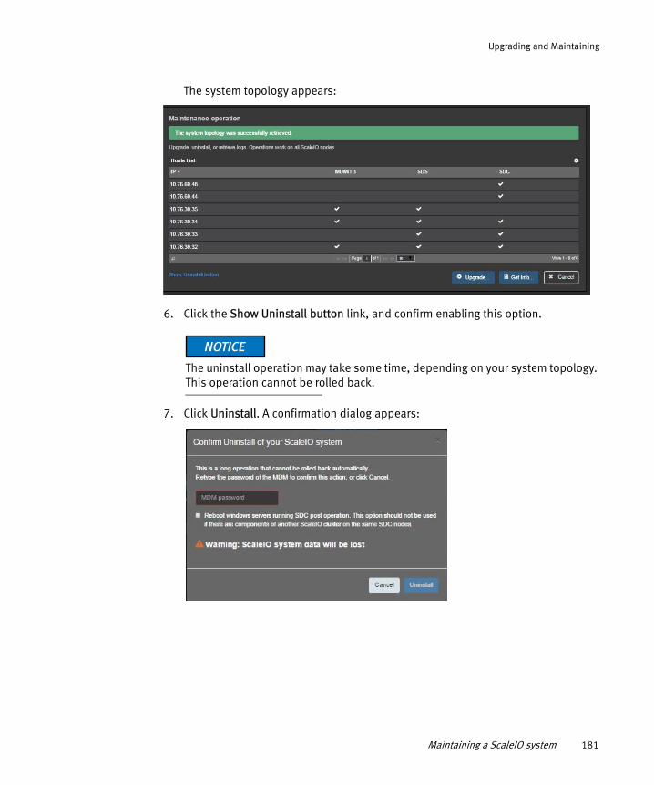
Upgrading and Maintaining
The system topology appears:
6. Click the Show Uninstall button link, and confirm enabling this option.
The uninstall operation may take some time, depending on your system topology. This operation cannot be rolled back.
7. Click Uninstall. A confirmation dialog appears:
Maintaining a ScaleIO system 181

Upgrading and Maintaining
Uninstalling an SDC component requires a machine restart. If you are uninstalling SDC components on Windows servers, select to enable automatic restart (on those servers only). Alternatively, you can manually restart these servers after removing the SDC.
On Linux servers, if the kernel module is busy, perform a manual restart.
8. Enter the MDM password, select to reboot servers (optional), and click Uninstall.
9. To monitor the uninstallation progress, click Monitor.
10. When the uninstallation is complete, click Mark operation completed.
Removing the VMware plug-inTo remove the plug-in, perform the following:
1. Run the script to remove the plug-in:
a. From the folder where you extracted the EMC-ScaleIO-vSphere-web-plugin-package-1.32-XXX.X.zip file, use PowerCLI to run the ScaleIOPluginSetup-1.32-XXX.X.ps1 script.
b. Select option 2, Unregister ScaleIO plugin.
2. Enter the vCenter credentials and confirm the script actions.
3. Log out, then log back in to the vSphere web client.
4. The plug-in is no longer registered.
182 EMC ScaleIO Installation Guide
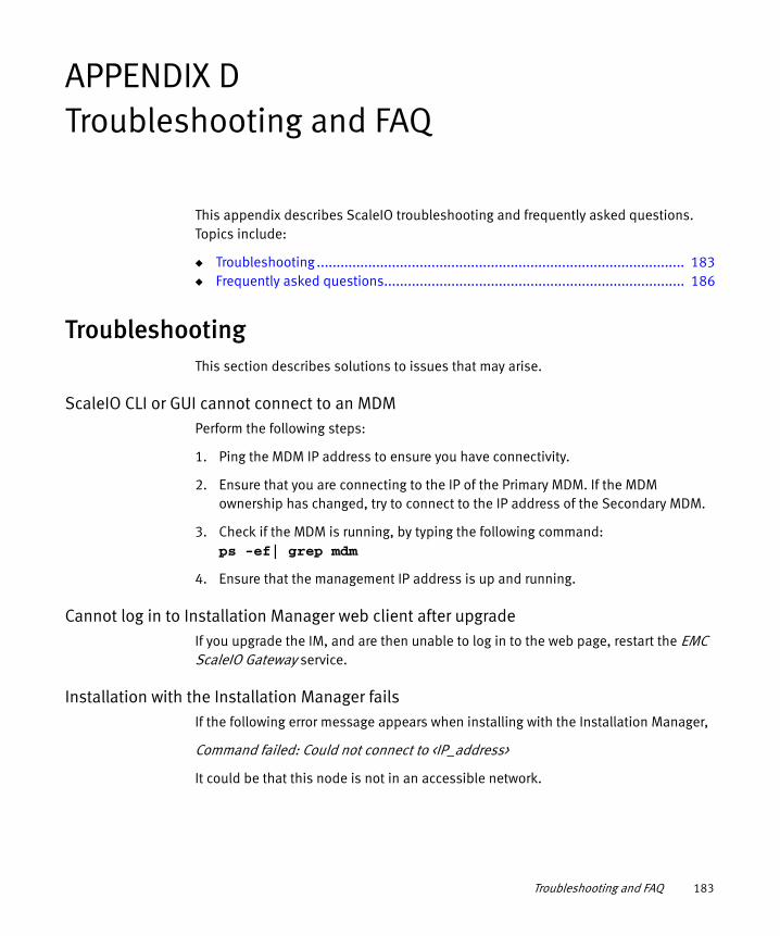
APPENDIX DTroubleshooting and FAQ
This appendix describes ScaleIO troubleshooting and frequently asked questions. Topics include:
◆ Troubleshooting ............................................................................................. 183◆ Frequently asked questions............................................................................ 186
TroubleshootingThis section describes solutions to issues that may arise.
ScaleIO CLI or GUI cannot connect to an MDMPerform the following steps:
1. Ping the MDM IP address to ensure you have connectivity.
2. Ensure that you are connecting to the IP of the Primary MDM. If the MDM ownership has changed, try to connect to the IP address of the Secondary MDM.
3. Check if the MDM is running, by typing the following command:ps -ef| grep mdm
4. Ensure that the management IP address is up and running.
Cannot log in to Installation Manager web client after upgradeIf you upgrade the IM, and are then unable to log in to the web page, restart the EMC ScaleIO Gateway service.
Installation with the Installation Manager failsIf the following error message appears when installing with the Installation Manager,
Command failed: Could not connect to <IP_address>
It could be that this node is not in an accessible network.
Troubleshooting and FAQ 183

Troubleshooting and FAQ
In the VMware plug-in, ScaleIO systems appear disconnected, or not supportedIf any of your registered ScaleIO systems contain an SDC that is installed on SVM (using iSCSI initiators instead of being directly installed on the ESX), all of your systems will appear to be unsupported or disconnected.
On the main EMC ScaleIO screen, an error message is displayed; in the ScaleIO Systems screen, the cluster state of all systems (even those that do not have SDC on SVM) will appear as Disconnected - not supported iSCSI.
In addition, all of your ScaleIO objects will appear with values of 0, as illustrated in the following figure:
To fix this problem, you must first locate, and then unregister all systems in which the SDC on SVM is present. When that is done, your other systems will become active.
Before you can re-register the systems that you unregistered, you will need to switch those SDCs to be installed directly on ESX, something that can be done only with the assistance of EMC Support. When that is complete, it is recommended to upgrade the entire system to the current version, as described in “Upgrading from a previous version” on page 165.
To identify which systems have SDC installed on SVM, log in to the Primary MDM, and run this command:
184 EMC ScaleIO Installation Guide

Troubleshooting and FAQ
scli --query_all_scsi_initiators
The following output indicates that there are no iSCSI initiators, thus no SDC on SVM:
Query all SCSI Initiators returned 0 initiators
Output similar to the following indicates that there are at least one SDC installed on SVM in the system:
Query all SCSI Initiators returned 1 initiators.
ID: 94a3553c00000000 Name: N/A IQN: aaa Not mapped to any volume
Installation Manager returns an errorIf you are unable to log in to the IM with the CLI, or in the web client, if an HTTP 404 Webpage not available error (or similar) is displayed, the IM may have been disabled.
For more information, refer to “Configuring the Installation Manager” on page 82.
After SDC installation, the ScaleIO SVM does not start automaticallyAfter deployment is completed, set all ScaleIOVMs to start automatically:
1. Click the ESX Configuration tab.
2. From the Software section, click Virtual Machine Startup/Shutdown.
3. Click Properties...
4. In the dialog box, select Allow virtual machines to start and stop automatically with the system.
5. Select the SVM and move it to the Automatic Startup list.
6. Click OK.
7. Repeat this process for all SVMs.
Troubleshooting 185

Troubleshooting and FAQ
Certificate error when installing SDC on Windows serversDue to a Microsoft Windows limitation, when installing an SDC component on a Windows 2008 R2 server, a certificate error, similar to the following may be displayed:
To solve this issue, ensure that Microsoft Security Update KB3033929 is installed.
Frequently asked questionsThis section addresses the following frequently asked question:
◆ “Using the same data network for different NICs” on page 187◆ “Mounting ScaleIO” on page 187◆ “Configuring ScaleIO devices in Linux LVM” on page 188◆ “Changing the LIA configuration file” on page 188◆ “The ScaleIO Gateway web server isn’t responding” on page 189◆ “Fixing keytool errors” on page 190◆ “Upgrading the Gateway when a custom certificate is used” on page 191
186 EMC ScaleIO Installation Guide

Troubleshooting and FAQ
◆ “Changing the shutdown port for the Tomcat server” on page 192◆ “Uploading a new OVA” on page 192◆ “Changing default ports” on page 193◆ “Associating ScaleIO volumes with physical disks” on page 193
Using the same data network for different NICsThis configuration is supported, but it could reduce efficiency of outgoing communication, and deny you the benefits of high availability of the multiple networks.
Mounting ScaleIOThe exposed ScaleIO volumes are connected to the servers via the network. To configure mounting options of ScaleIO devices, follow the instructions for your OS.
Use persistent device names, described in full in “Associating ScaleIO volumes with physical disks” on page 193:
To mount, perform the following:
1. Determine the /dev/disk/by-id correlation to /dev/sciniX by running the following command:
ls -l /dev/disk/by-id/ |grep scini
Output, similar to the following, appears:
lrwxrwxrwx 1 root root 12 Mar 2 05:35 emc-vol-7ec27ef55b8f2108-85a0f0330000000a -> ../../scinialrwxrwxrwx 1 root root 12 Mar 2 05:35 emc-vol-7ec27ef55b8f2108-85a0f03200000009 -> ../../sciniblrwxrwxrwx 1 root root 12 Mar 2 05:35 emc-vol-7ec27ef55b8f2108-85a0f02c00000003 -> ../../scinic
2. Run the mount command:
mount /dev/disk/by-id/<EMC-vol-id>
Example mount /dev/disk/by-id/emc-vol-7ec27ef55b8f2108-85a0f0330000000a /mnt_scinia
3. To make the mount command persistent, edit the /etc/fstab file, according to the instructions for your operating system:
• RHEL
In /etc/fstab use a text editor to add _netdev to the ScaleIO mount lines:
Example: /dev/disk/by-id/emc-vol-7ec27ef55b8f2108-85a0f0330000000a /mnt_scinia ext3_netdev 0 0
Frequently asked questions 187

Troubleshooting and FAQ
Ensure that you comply with the netdev and syntax rules for your file system, as described in the man page.
• SLES
In /etc/fstab use a text editor to add nofail to the ScaleIO mount lines:
Example: /dev/disk/by-id/emc-vol-7ec27ef55b8f2108-85a0f0330000000a /mnt_scinia ext3 nofail 0 0
Ensure that you comply with the nofail and syntax rules for your file system, as described in the man page.
Configuring ScaleIO devices in Linux LVMTo configure ScaleIO devices, perform the following:
1. Edit the file /etc/lvm/lvm.conf by adding the following line:
types = [ "scini", 16 ]
2. If only ScaleIO scini devices are to be used, you can add the following filter:
filter = [ "a|/dev/scini*|", "r/.*/" ]
3. Once configured, the lvmdiskscan command should yield results similar to the following:
/dev/scinia [ 96.00 GiB] LVM physical volume/dev/scinib [ 320.00 GiB] LVM physical volume/dev/scinic1 [ 56.00 GiB]/dev/scinid [ 32.00 GiB]1 disk1 partition2 LVM physical volume whole disks0 LVM physical volumes
4. Continue with normal LVM steps.
Changing the LIA configuration fileYou can change the default behavior of the LIA by editing the configuration file:
◆ WindowsC:\Program Files\emc\scaleio\LIA\cfg\conf.txt
◆ Linux/opt/emc/scaleio/lia/cfg/conf.txt
The following values are some that are relevant to LIA behavior:
188 EMC ScaleIO Installation Guide

Troubleshooting and FAQ
lia_token=5lia_enable_install=1lia_enable_uninstall=1lia_enable_configure_call_home=0lia_enable_configure_fetch_logs=1
The ScaleIO Gateway web server isn’t responding
The ScaleIO Gateway (REST service, Installation Manager) may be disabled:
The ScaleIO Gateway seems to be locked or disabled, and returns the HTTP status code 401 or 403.
Solution
◆ Ensure that the Gateway is enabled, as described in “Enabling and disabling Gateway components” on page 147.
◆ In the gatewayUser.properties file, ensure that the gateway-admin.password property has a non-blank password. If the password is blank, the gateway has been locked. Unlock it by using the Installation Manager CLI command im generate_password, described in Table 7 on page 158.
◆ The following table shows the location of the gatewayUser.properties file:
The ScaleIO Gateway web server isn't responsive and the following error appears in the tomcat.log file:
◆ WindowsC:\Program Files\EMC\ScaleIO\Gateway\logs\tomcat.log
◆ Linux/opt/emc/scaleio/gateway/logs
Gateway installed on Location of gatewayUser.properties file
Windows, 32-bit C:\Program Files (x86)\EMC\ScaleIO\Gateway\webapps\ROOT\WEB-INF\classes\
Windows, 64-bit C:\Program Files\EMC\ScaleIO\Gateway\webapps\ROOT\WEB-INF\classes\
Linux /opt/emc/scaleio/gateway/webapps/ROOT/WEB-INF/classes
Frequently asked questions 189

Troubleshooting and FAQ
2014-06-21 22:50:57,113 [main] ERROR o.a.coyote.http11.Http11NioProtocol - Failed to initialize end point associated with ProtocolHandler ["http-nio-443"] java.net.BindException: Address already in use: bind
Solution
Perform one of the following:
◆ Find the service/daemon that is currently occupying that port and stop it, using netstat -anb on Windows or netstat -alp on Linux. On Windows, one of the common applications that occupies this port is the VMware workstation, which uses this port for the shared VM feature. You can configure VMware workstation to use a different port via the Settings dialog, or you can disable the shared VM feature.
Once the port is free, restart the scaleio-gateway service:
• Windows
Restart the EMC ScaleIO Gateway service
• Linux
Type the command service scaleio-gateway restart
◆ Change the ScaleIO Gateway web server to run on a different port, as described in “Changing default ports” on page 193.
After doing so, restart the ScaleIO Gateway service/daemon, as described above. Access the Gateway with the new port. For example: https://<host>:<port>
Fixing keytool errors
Error during rpm installation command
Error message No keytool path was found. Please pass SIO_GW_KEYTOOL as an argument to the rpm installation command.
If a message similar to this is displayed after executing the rpm command to install the Gateway, add the location of the /bin/keytool file on your server to the command.
Example rpm command:
SIO_GW_KEYTOOL=/usr/lib/jvm/java-1.6.0-openjdk-1.6.0.0.x86_64/jre rpm -U <gateway_installation_file_name>.rpm
190 EMC ScaleIO Installation Guide

Troubleshooting and FAQ
Error during rpm upgrade command
Error message: No keytool path was found. Set the environment variable SIO_GW_KEYTOOL
If a message similar to this is displayed after executing the rpm command to upgrade the Gateway, add the location of the /bin/keytool file on your server to the command.
Example command:
SIO_GW_KEYTOOL=/usr/java/default/bin/ rpm -Uvh /tmp/EMC-ScaleIO-gateway-1.32-363.0.noarch.rpm
Error during log in to Installation Manager CLI
Error message cannot find keytool utility
Could not log in
If a message similar to this is displayed when running the im login command with a certificate, it is caused by the inability to find the keytool utility, which is located in the Java path. To correct this issue, add the location of the java_path to the command. This is only necessary when providing a certificate; if using the --no_certificate_validation flag, it is not necessary.
Example command:
im login --host 10.76.61.35 --username admin --password 123 --port 443 --cer "C:\InstallationManager\ScaleIO.cer" --java_flag <java_path>
Upgrading the Gateway when a custom certificate is usedIf a custom security certificate is used on the ScaleIO Gateway (Windows and Linux environments), you must save a copy of the certificate (*.keystore file) and the catalina.properties file before you upgrade the gateway. After the upgrade is complete, you must copy these files back to their original location.
The default file locations, per operating system, are:
Linux:
/opt/emc/scaleio/gateway/conf/catalina.properties
/opt/emc/scaleio/gateway/conf/certificates/.keystore
Frequently asked questions 191

Troubleshooting and FAQ
Windows (64 bit):
C:\Program Files\EMC\ScaleIO\Gateway\conf\catalina.properties
C:\Program Files\EMC\ScaleIO\Gateway\conf\certificates\.keystore
Windows (32-bit):
C:\Program Files (x86)\EMC\ScaleIO\Gateway\conf\catalina.properties
C:\Program Files (x86)\EMC\ScaleIO\Gateway\conf\certificates\.keystore
What to do when the default self-signed certificate expiresIf the default self-signed security certificate is used on the ScaleIO Gateway, it expires after approximately one year. When you upgrade the gateway, the self-signed certificate is automatically replaced with a new one. If your self-signed security certificate expires, you can create a new one using the Java keytool utility.
For more information, see “Certificate management for ScaleIO Gateway” on page 149.
Changing the shutdown port for the Tomcat serverBy default, Tomcat listens on port 8005 for the shutdown command; all applications within this context are shutdown.
You can change the port number by changing the settings in the server.xml file (/conf/server.xml), as follows:
Original—<Server port="8005" shutdown="SHUTDOWN">
Edited—<Server port="8008" shutdown="SHUTDOWN">
Uploading a new OVAIf you have already used the OVA to create a template, you cannot create another template with the same name in the same datacenter.
Either remove the original template first, or use the ScaleIOPluginSetup-1.31-XXX.X.ps1 script, option #3, to assign a different name to the new template.
192 EMC ScaleIO Installation Guide

Troubleshooting and FAQ
You can also upload the OVA manually using the VMware OVA upload tools. Configure the networks manually, after deployment or during the wizard menus. For more information, see the VMware user guides.
Changing default portsThe following table lists the TCP ports that are used by ScaleIO. Prior to installing or upgrading a system, ensure that these ports are not in use by other processes.
If they are, either free these ports or change the ScaleIO ports to another available port.
1. After changing either of the Gateway ports, you must restart the Gateway service/daemon, as described in “The ScaleIO Gateway web server isn’t responding” on page 189.
Associating ScaleIO volumes with physical disksThis section describes how to associate volumes with physical disks.
Get ScaleIO volume information, by running the scli --query_all_volumes (or --query_all, or --query_volume) command.
Port used by Port # File to change
Field to modify (or to add, if it does not exist)
MDM listener
6611Notice: Cannot be modified, and must be available
Cluster listener
9011 /opt/emc/scaleio/mdm/cfg/conf.txt actor_cluster_port=<new-port>
Tie Breaker listener
9011 /opt/emc/scaleio/tb/cfg/conf.txt voter_cluster_port=<new-port>
SDS listener
7072 /opt/emc/scaleio/sds/cfg/conf.txt tgt_port=<new-port>
LIA listener 9099 /opt/emc/scaleio/lia/cfg/conf.txt lia_port=<new-port>
Gateway (secure)
443 {gateway installation directory}\conf\server.xml
redirectPort=<new-port>1
Connector port=<new-port>
Gateway (not secure)
80 {gateway installation directory}\conf\server.xml
Connector port=<new-port>1
Frequently asked questions 193

Troubleshooting and FAQ
Output, similar to the following appears:
This output shows the Volume ID and name, as well as other volume information.
Linux
On the SDC host, get the operating system volume information that correlates to the ScaleIO scini device name, by running the following command:
# ls -l /dev/disk/by-id/ |grep scini
Output, similar to the following appears:
This output shows the scini volume name and the volume ID.By matching the volume ID in both outputs, you can match the operating system names, sciniX, with the ScaleIO volume name.For example:
◆ scinia = fac22a6300000000 = vol0
◆ scinic = fac22a6400000001 = vol1
194 EMC ScaleIO Installation Guide

Troubleshooting and FAQ
Alternatively, run the sg_inq /dev/sciniX SCSI query command. The result of this command includes the EMC volume ID at the bottom, as illustrated in the following figure:
Note: Running this command requires that the sg3_utils are installed on the Linux host.
Windows
The sg_inq.exe file was added to the MSI installation and can be found in the following location: C:\Program Files\EMC\ScaleIO\SDC\diag\
Run the sg_inq HardiskX SCSI query command. The result of this command includes the EMC volume ID at the bottom.
Frequently asked questions 195

Troubleshooting and FAQ
196 EMC ScaleIO Installation Guide

GLOSSARY
This glossary contains terms related to ScaleIO. These terms are used in ScaleIO management tools.
A
Active Backward Rebuild A copy of stored data is currently being restored and updated to a recovered server.
Active Forward Rebuild A copy of stored data is currently being rebuilt on another server, due to planned or unplanned shutdown of a server.
B
Backward Rebuild Data is rebuilt on servers that went offline and became active again. Forward rebuilds can take a long time, and therefore, it can be quicker to restore and update the data on a server which has come back online, than it is to do an entire rebuild on a different server.
BWC Bandwidth counters.
C
Cache Random access electronic storage used to retain frequently used data for faster access by the channel. ScaleIO can be configured to use RAM cache on the storage devices in the system, to improve system performance.
Cache Hit Rate The percentage of I/Os from cache.
Cache Skip Data is written directly to storage, bypassing the cache. Reasons for cache skips include: I/Os were too large, the cache device was busy, or I/Os were unaligned. The cache can also be configured to always work in passthrough mode.
Cache Writes HandlingMode
The caching write-mode used by the system: passthrough mode (writes to storage only), or cached mode (by default, writes both to cache and to storage).
EMC ScaleIO Installation Guide 197

Glossary
Cluster Mode ScaleIO is controlled by a cluster of MDM nodes, consisting of a primary, secondary, and tie-breaker node.
D
Degraded Capacity The capacity is available, but is not protected in case of another failure
Device Physical storage device, such as a flash drive, or magnetic disk
DRL Dirty Region Logging: DRL bits indicate if data is in-writing to a certain location. Once the data is written in both primary and secondary locations, the DRL bit associated with the written location is cleared. These bits can be either stored in DRAM only (memory_only) or also backed up in non-volatile memory (hardened). The former delivers better I/O performance; the latter reduces data movement following a power-cycle giving rise to a faster rebuild.
F
Failed Capacity The capacity is inaccessible due to a failure, and data integrity is at risk
Fault Sets A logical entity that ensures that SDS data is backed up on SDSs that belong to other Fault Sets, thus preventing double-point-of-failure scenarios if rack power outages occur.
Forward Rebuild Data in storage will be rebuilt on another server, due to planned or unplanned shutdown of a server.
I
ID Identifier, a unique sequence of characters that identifies an object in the system. In some CLI commands, an ID can be used to specify a system component.
IP Role The role of the IP address configured for an SDS. Each SDS can have several IP addresses associated with it. Each IP address can serve a different purpose, or role. IP roles include: SDS, SDC, or both SDS and SDC.
M
Management IPs The IP addresses of the MDMs defined in the system that can be used to access the MDM from CLI, GUI and REST.
198 EMC ScaleIO Installation Guide

Glossary
Management Port The Port number used by the MDM for purposes of communicating with the nodes in the ScaleIO network.
MDM The Meta Data Manager, which configures and monitors the ScaleIO system.
P
Pending BackwardRebuild
A backward rebuild is waiting in a queue, and will be performed when possible, according to rebuild throttling policy.
Primary MDM IP The IP address of the primary MDM, used for managing the ScaleIO network.
Protected Capacity Capacity that has an accessible copy in the system, in case of failure.
Protection Domain A unique set of SDSs grouped together for reliability and tenancy separation.
R
RAM Cache RAM that is reserved for caching storage devices in Storage Pool.
Rebalance When ScaleIO detects lopsided use of storage capacity, or when new nodes are added, it redistributes data across the nodes, in order to improve performance.
Restricted MDM Mode A mode set in which commands can only be performed from an MDM machine.
Restricted SDC Mode Only approved SDCs can access the MDM. When this mode is enabled, volumes can only be added to approved SDCs.
Rebuild When ScaleIO detects a failure in the network, it creates a new copy of the data from the failed component, in a new location, to ensure data integrity.
S
SDC ScaleIO Data Client, a lightweight device driver that exposes ScaleIO volumes as block devices to the application residing on the same server on which the SDC is installed.
SDS ScaleIO Data Server, which manages the capacity of a single server and acts as a back-end for data access. The SDS is installed on all servers contributing storage devices to the ScaleIO system.
EMC ScaleIO Installation Guide 199

Glossary
Single Mode A single MDM manages the ScaleIO network. This mode has no backup protection.
Snapshot Capacity The amount of capacity occupied by snapshots of volumes.
Spare Capacity Capacity that is reserved for system use, when recovery from failure is required. This capacity cannot be used for storage purposes.
Spare Percentage Policy This policy determines the amount of capacity that must always be reserved as free space.
Storage Pool A sub-set of physical storage devices in a Protection Domain. Each storage device can only belong to one Storage Pool. User volumes will always use the storage of a single Storage Pool.
T
Thick Capacity Capacity allocated for thick volumes.
Thick ProvisionedVolume
Volume that has all its capacity pre-allocated on creation.
Thin Capacity Capacity allocated for thin volumes.
Thin Provisioned Volume Volume for which capacity is allocated on demand (by writing to the volume).
Throttling Throttling controls resource prioritization for rebuild and rebalance processes. Throttling can be controlled per Protection Domain or per Storage Pool (by configuring rebuild and rebalance policies).
Tie-Breaker The Tie-Breaker is used to determine which of the MDM nodes will take control over the ScaleIO system. As the number of MDMs is even, the Tie-Breaker ensures that there will always be one primary MDM achieving cluster quorum.
U
Unavailable Capacity Capacity that is not being used, but is also unavailable (due to server outage).
Unused Capacity Capacity that is not currently being used for any purpose in the system.
200 EMC ScaleIO Installation Guide

Glossary
V
Volume A general term referring to a storage device. In the ScaleIO system, a volume consists of multiple blocks spread evenly on a storage pool devices.
W
Widget The full screen view can be minimized into a widget, which is a small window that floats on your screen, over other applications. Property sheets can also be minimized into widgets.
EMC ScaleIO Installation Guide 201

Glossary
202 EMC ScaleIO Installation Guide


![[Vendor Solution Name] Storage Solution...Flash Storage System. Each storage domain is a “data container” that isolates data from other storage domains, providing independence](https://img.pdfslide.net/doc/110x75/5ed2ec37d33bf86ae879591e/vendor-solution-name-storage-solution-flash-storage-system-each-storage-domain.jpg)