Embed Size (px)
DESCRIPTION
manual hammer test
Citation preview

Bedienungsanleitung
Operating Instructions
Mode d’emploi
BetonprüfhammerConcrete Test HammerScléromètre à bétonN/NR - L/LR
N/L
NR/LR

Proceq SARingstrasse 2CH-8603 SchwerzenbachSwitzerland
Tel.: + 41 (0)43 355 38 00Fax: + 41 (0)43 355 38 12E-Mail: [email protected]: www.proceq.com
Technische Änderungen vorbehaltenSubject to changeModifications techniques réservées
Copyright © 2006 by Proceq SA 820 310 01D/E/F ver 09 2006

Engl
ish
© 2006 Proceq SA Contents 1
Contents
1 Safety . . . . . . . . . . . . . . . . . . . . . . . . . . . . . . . . . . 2 General Information . . . . . . . . . . . . . . . . . . . . . . . 2 Liability . . . . . . . . . . . . . . . . . . . . . . . . . . . . . . . . . 2 Safety Regulations . . . . . . . . . . . . . . . . . . . . . . . . 3 Standards and Regulations Applied. . . . . . . . . . . 3
2 Measurement . . . . . . . . . . . . . . . . . . . . . . . . . . . 4 Measuring Principle . . . . . . . . . . . . . . . . . . . . . . . 4 Measuring Procedure. . . . . . . . . . . . . . . . . . . . . . 4 Outputting and Evaluating Data . . . . . . . . . . . . . . 5 Conversion Curves. . . . . . . . . . . . . . . . . . . . . . . . 6 Factors Affecting the Values. . . . . . . . . . . . . . . . . 11
3 Maintenance . . . . . . . . . . . . . . . . . . . . . . . . . . . . 15 Performance Check . . . . . . . . . . . . . . . . . . . . . . . 15 Cleaning After Use . . . . . . . . . . . . . . . . . . . . . . . . 15 Fitting a New Recording Paper Roll. . . . . . . . . . . 15 Storage. . . . . . . . . . . . . . . . . . . . . . . . . . . . . . . . . 16 Maintenance Procedure . . . . . . . . . . . . . . . . . . . . 16
4 Data . . . . . . . . . . . . . . . . . . . . . . . . . . . . . . . . . . . 19 Form of Delivery. . . . . . . . . . . . . . . . . . . . . . . . . . 19 Accessories . . . . . . . . . . . . . . . . . . . . . . . . . . . . . 19 Technical Data . . . . . . . . . . . . . . . . . . . . . . . . . . . 19
For more information, please refer to the Info-Sheet 2003 09 45 BPH-2 EURO-Anvil

2 Safety © 2006 Proceq SA
1 Safety1 .1 General Information1 .1 .1 Basic InformationThe concrete test hammer is designed according to state-of-the-art technology and the recognized safety regulations. Please read through these operating in-structions carefully before initial startup. They contain important information about safety, use and maintenance of the concrete test hammer.
1 .1 .2 Designated UseThe concrete test hammer is a mechanical device used for performing rapid, non-destructive quality testing on materials in accordance with the customer's specifica-tions; in most cases, however, the material involved is concrete.The device is to be used exclusively on the surfaces to be tested and on the testing anvil.
1 .2 LiabilityOur "General Terms and Conditions of Sale and Delivery" apply in all cases. Warranty and liability claims arising from personal injury and damage to property cannot be upheld if they are due to one or more of the following causes:
- Failure to use the concrete test hammer in accordance with its designated use- Incorrect performance check, operation and mainte- nance of the concrete test hammer- Failure to adhere to the sections of the operating instructions dealing with the performance check, ope- ration and maintenance of the concrete test hammer- Unauthorized structural modifications to the concrete test hammer- Serious damage resulting from the effects of foreign bodies, accidents, vandalism and force majeure
1 .3 Safety Regulations1 .3 .1 General Information- Perform the prescribed maintenance work on schedule - Carry out a performance check once the maintenance work has been completed.- Handle and dispose of lubricants and cleaning agents responsibly.
1 .3 .2 Unauthorized OperatorsThe concrete test hammer is not allowed to be operated by children and anyone under the influence of alcohol, drugs or pharmaceutical preparations.Anyone who is not familiar with the operating instructions must be supervised when using the concrete test hammer.

Engl
ish
© 2006 Proceq SA Safety 3
1 .3 .3 Safety IconsThe following icons are used in conjunction with all important safety notes in these operating instructions.
Danger! Thisnoteindicatesariskofseriousor
fatalinjuryintheeventthatcertainrules ofbehavioraredisregarded.
Warning! Thisnotewarnsyouabouttheriskofmaterial
damage,financiallossandlegalpenalties (e.g.lossofwarrantyrights,liability cases,etc.).
Thisdenotesimportantinformation.
1 .4 Standards and Regulations Applied- ISO/DIS 8045 International
- EN 12 504-2 Europe
- ENV 206 Europe
- BS 1881, part 202 Great Britain
- DIN 1048, part 2 Germany
- ASTM C 805 USA
- ASTM D 5873 ( Rock ) USA
- NFP 18-417 France
- B 15-225 Belgium
- JGJ/ T 23-2001 China
- JJG 817-1993 China
4 Measurement © 2006 Proceq SA
2 Measurement2 .1 Measuring PrincipleThe device measures the rebound value R. There is a specific relationship between this value and the hardness and strength of the concrete.The following factors must be taken into account when ascertaining rebound values R:- Impact direction: horizontal, vertically upwards or downwards- Age of the concrete- Size and shape of the comparison sample ( cube, cylinder )Models N and NR can be used for testing:- Concrete items 100 mm or more in thickness- Concrete with a maximum particle size ≤ 32 mmModels L and LR can be used for testing:- Items with small dimensions ( e.g. thin - walled items with a thickness from 50 to 100 mm ) Ifnecessary,clamptheitemstobetested priortomeasurementinordertoprevent thematerialdeflecting.- Items made from artificial stone which are sensitive to impacts Preferablyperformmeasurementsat
temperaturesbetween10°Cand50°Conly.
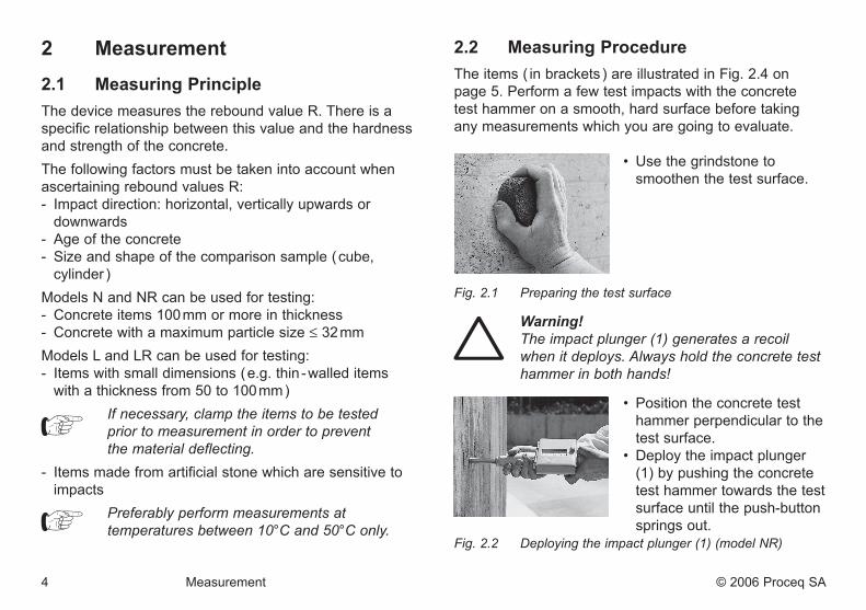
2 .2 Measuring ProcedureThe items ( in brackets ) are illustrated in Fig. 2.4 on page 5. Perform a few test impacts with the concrete test hammer on a smooth, hard surface before taking any measurements which you are going to evaluate.
• Use the grindstone to smoothen the test surface.
Fig.2.1 Preparingthetestsurface
Warning! Theimpactplunger(1)generatesarecoil whenitdeploys.Alwaysholdtheconcretetest hammerinbothhands!
• Position the concrete test hammer perpendicular to the test surface. • Deploy the impact plunger (1) by pushing the concrete test hammer towards the test surface until the push-button
springs out.Fig.2.2 Deployingtheimpactplunger(1)(modelNR)

Engl
ish
© 2006 Proceq SA Measurement 5
Danger! Alwaysholdtheconcretetesthammerin
bothhands,perpendiculartothetest surface,beforeyoutriggertheimpact!
Eachtestsurfaceshouldbetestedwithatleast 8to10impacts.
Theindividualimpactpointsmustbespacedat least20mmapart.
• Position the concrete test hammer perpendicular to and against the test surface. Push the concrete test ham- mer against the test surface at moderate speed until the impact is triggered.
Fig2.3 Performingthetest(illustrationshowsmodelNR)
• If you are using models N and L, press the push-button (6) to lock the impact plunger (1) after every impact. Then read off and note down the rebound value R indi-cated by the pointer (4) on the scale (19).
• If you are using models NR and LR, the rebound value R is automatically printed on the recording paper. It is only necessary to lock the impact plunger (1) using the push button (6) after the last impact.
Fig.2.4 Readingthetestresultfromthescale(19)on modelsNandL
2 .3 Outputting and Evaluating Data2 .3 .1 OutputModels N and LAfter every impact, the rebound value R is displayedby the pointer (4) on the scale (19) of the device.Models NR and LRThe rebound value R is automatically registered on the recording paper.It is possible to record about 4000 test impacts on each roll.
2 .3 .2 EvaluationTake the average of the 8 - 10 rebound values R which you have measured. Donotincludevalueswhicharetoohighor
toolow(thelowestandhighestvalues)in yourcalculationoftheaveragevalue.
1
4 19
6
6 Measurement © 2006 Proceq SA
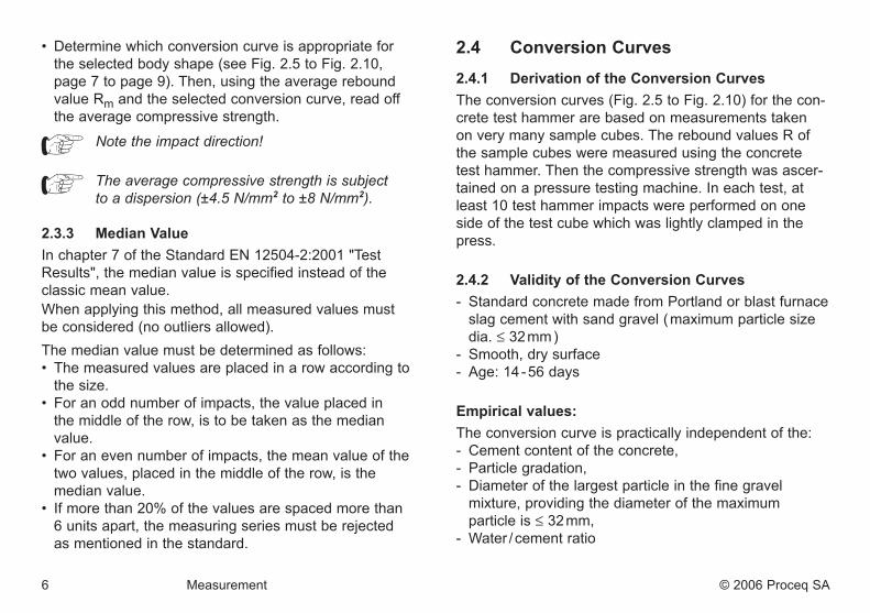
• Determine which conversion curve is appropriate for the selected body shape (see Fig. 2.5 to Fig. 2.10, page 7 to page 9). Then, using the average rebound value Rm and the selected conversion curve, read off the average compressive strength.
Notetheimpactdirection!
Theaveragecompressivestrengthissubject toadispersion(±4.5N/mm2to±8N/mm2).2 .3 .3 Median ValueIn chapter 7 of the Standard EN 12504-2:2001 "Test Results", the median value is specified instead of the classic mean value.When applying this method, all measured values must be considered (no outliers allowed).The median value must be determined as follows: • The measured values are placed in a row according to the size. • For an odd number of impacts, the value placed in the middle of the row, is to be taken as the median value. • For an even number of impacts, the mean value of the two values, placed in the middle of the row, is the median value. • If more than 20% of the values are spaced more than 6 units apart, the measuring series must be rejected as mentioned in the standard.
2 .4 Conversion Curves2 .4 .1 Derivation of the Conversion CurvesThe conversion curves (Fig. 2.5 to Fig. 2.10) for the con-crete test hammer are based on measurements taken on very many sample cubes. The rebound values R of the sample cubes were measured using the concrete test hammer. Then the compressive strength was ascer-tained on a pressure testing machine. In each test, at least 10 test hammer impacts were performed on one side of the test cube which was lightly clamped in the press.
2 .4 .2 Validity of the Conversion Curves- Standard concrete made from Portland or blast furnace slag cement with sand gravel ( maximum particle size dia. ≤ 32 mm )- Smooth, dry surface- Age: 14 - 56 days
Empirical values:The conversion curve is practically independent of the:- Cement content of the concrete,- Particle gradation,- Diameter of the largest particle in the fine gravel mixture, providing the diameter of the maximum particle is ≤ 32 mm,- Water / cement ratio
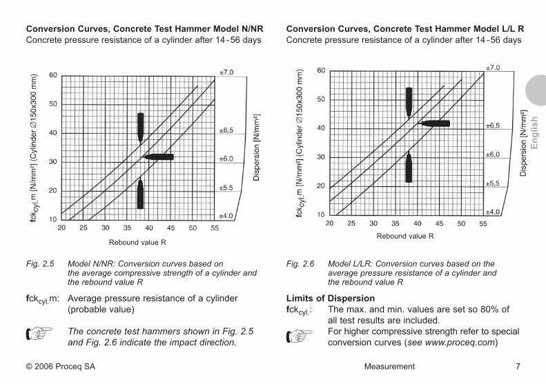
Conversion Curves, Concrete Test Hammer Model L/L RConcrete pressure resistance of a cylinder after 14 - 56 days
Rebound value R
Fig.2.6 ModelL/LR:Conversioncurvesbasedonthe averagepressureresistanceofacylinderand thereboundvalueR
Limits of Dispersion fckcyl.: The max. and min. values are set so 80% of all test results are included. For higher compressive strength refer to special
conversion curves (see www.proceq.com)
Engl
ish
© 2006 Proceq SA Measurement 7
Conversion Curves, Concrete Test Hammer Model N/NRConcrete pressure resistance of a cylinder after 14 - 56 days
Rebound value R
Fig.2.5 ModelN/NR:Conversioncurvesbasedon theaveragecompressivestrengthofacylinderand thereboundvalueR
fckcyl.m: Average pressure resistance of a cylinder (probable value)
TheconcretetesthammersshowninFig.2.5 andFig.2.6indicatetheimpactdirection.
8 Measurement © 2006 Proceq SA
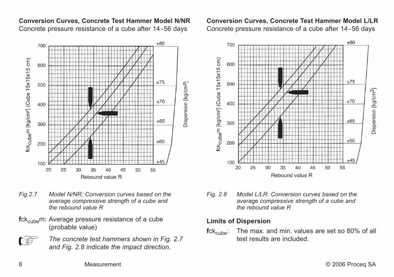
Conversion Curves, Concrete Test Hammer Model N/NRConcrete pressure resistance of a cube after 14 - 56 days
Dis
pers
ion
[kg/
cm2 ]
Fig.2.7 ModelN/NR:Conversioncurvesbasedonthe averagecompressivestrengthofacubeand thereboundvalueR
fckcubem: Average pressure resistance of a cube (probable value)
TheconcretetesthammersshowninFig.2.7 andFig.2.8indicatetheimpactdirection.
Conversion Curves, Concrete Test Hammer Model L/LRConcrete pressure resistance of a cube after 14 - 56 days
Fig.2.8 ModelL/LR:Conversioncurvesbasedonthe averagecompressivestrengthofacubeand thereboundvalueR
Limits of Dispersionfckcube: The max. and min. values are set so 80% of all test results are included.
Dis
pers
ion
[kg/
cm2 ]

Conversion Curves, Concrete Test Hammer Model L/LRConcrete pressure resistance of a cylinder after 14 - 56 days
Dis
pers
ion
[psi
]
Fig.2.10 ModelL/LR:Conversioncurvesbasedonthe averagecompressivestrengthofacylinder andthereboundvalueR
Limits of Dispersionfckcube: The max. and min. values are set so 80% of all test results are included.
Engl
ish
© 2006 Proceq SA Measurement 9
Conversion Curves, Concrete Test Hammer Model N/NRConcrete pressure resistance of a cylinder after 14 - 56 days
Dis
pers
ion
[psi
]
Fig.2.9 ModelN/NR:Conversioncurvesbasedon theaveragecompressivestrengthofacylinder andthereboundvalueR
fckcyl.m: Average pressure resistance of a cylinder (probable value)
TheconcretetesthammersshowninFig.2.9 andFig.2.10indicatetheimpactdirection.

2 .4 .3 Additional Conversion CurvesIn addition to the two well known curves from Proceq SA, we provide you four new curves developed in Japan that were based on exhaustive tests.
Portland Cement J for concrete with Portland cement (similar to curve B-Proceq) Early Strength J for early strength concrete made from Portland cement Blast Furnace J for concrete made from blast Furnace cement Average Curve J is the mean curve of curves 6, 7 and 8
nb: In Japan, only the curve "Average" is used.
Werecommendusingtheindividualcurvesiftherespectiveconcretequalityisknown.
The four curves are shown in Fig. 2.7 together with the B-Proceq curve.
The curves are valid for horizontal impacts and for the conversion to a compressive strength in N/mm2 evalu-ated with concrete cubes 150/150/150 mm. For other impact directions and sample size and shape, the respective factors must be considered additionally.
For the user of the conversion curves, each "Japan" curve is individually shown together with the B-Proceq curve in Fig. 2.8 to 2.10
B-ProceqPortland CementEarly StrengthBlast FurnaceAverage Curve
20 25 30 35 40 45 50
60
50
40
30
20
10
fc in
N/m
m2
(cub
e 15
0/15
0/15
0 m
m)
Rebound Value R
Fig2.7 AllJ-CurveswiththeProceq-B-Curve
B-ProceqPortland Cement
20 25 30 35 40 45 50
60
50
40
30
20
10
fc in
N/m
m2
(cub
e 15
0/15
0/15
0 m
m)
Rebound Value R
Fig.2.8 J-Curve"PortlandZement"
10 Measurement © 2006 Proceq SA

B-ProceqEarly Strength
20 25 30 35 40 45 50
60
50
40
30
20
10
fc in
N/m
m2
(cub
e 15
0/15
0/15
0 m
m)
Rebound Value R
Fig.2.9 J-Curve"EarlyStrength"
B-ProceqBlast Furnace
20 25 30 35 40 45 50
60
50
40
30
20
10
fc in
N/m
m2
(cub
e 15
0/15
0/15
0 m
m)
Rebound Value R
Fig2.10 J-Curve"BlastFurnace"
2 .5 Factors Affecting the Values2 .5 .1 Direction of ImpactThe measured rebound value R is dependent on the impact direction.
2 .5 .2 Shape coeficientThe compressive strength measured in a pressure testing machine depends on the shape and size of the sample.
Thesamplesprescribedforuseinthe
particularcountrymustbetakenintoaccount whenconvertingthereboundvalueRinto compressivestrength.
In the conversion curves on page 7 to page 11, the values for compressive strength are specified for cylin-ders (Ø 150 x 300 or Ø 6" x 12") and for cubes (length of side 15 cm). The following shape coefficients are familiar from the literature:
Cube 150 mm 200 mm 300 mmShapecoeficient
1 .001.25
0.951.19
0.851.06
Cylinder Ø 150x300 mmØ 6“x12“
Ø 100x200 mm Ø 200x200 mm
Shapecoeficient
0.801.00
0.851.06
0.951.19
Drill core Ø 50x56 mm Ø 100x100 mm Ø 150x150 mmShapecoeficient
1.041.30
1.021.28
1.001.25
© 2006 Proceq SA Measurement 11
Engl
ish

Example:A cube with a side length of 200 mm is used for the determination of the compressive strength with the pres-sure testing machine. In this case the strength values shown in the conversion curves in Fig. 2.9 and Fig. 2.10 on page 9 (for cylinders Ø 6"x12") must be multiplied by the shape coefficient of 1.19.
2 .5 .3 Time CoefficientThe age of the concrete and its carbonate penetration depth can significantly increase the measured rebound values R. It is possible to obtain accurate values for the effective strength by removing the hard, carbonate- impregnated surface layer using a manual grinding machine over a surface area of about Ø 120 mm and per-forming the measurement on the non-carbonate- impregnated concrete. The time coefficient, i.e. the amount of the increased rebound values R, can be obtained by taking additional measurements on the carbonate-impregnated surface. Rm carb. Rm carb.Time coeff. Zf = ⇒ Rm n.c. = Rm n.c. Zf
Rm carb.: Average rebound value R, measured on carbonate-impregnated concrete surfaceRm n.c.: Average rebound value R, measured on non- carbonate-impregnated concrete surface
Another possibility to consider the carbonation depth is given by the chinese standard JGJ/T 23-2001.
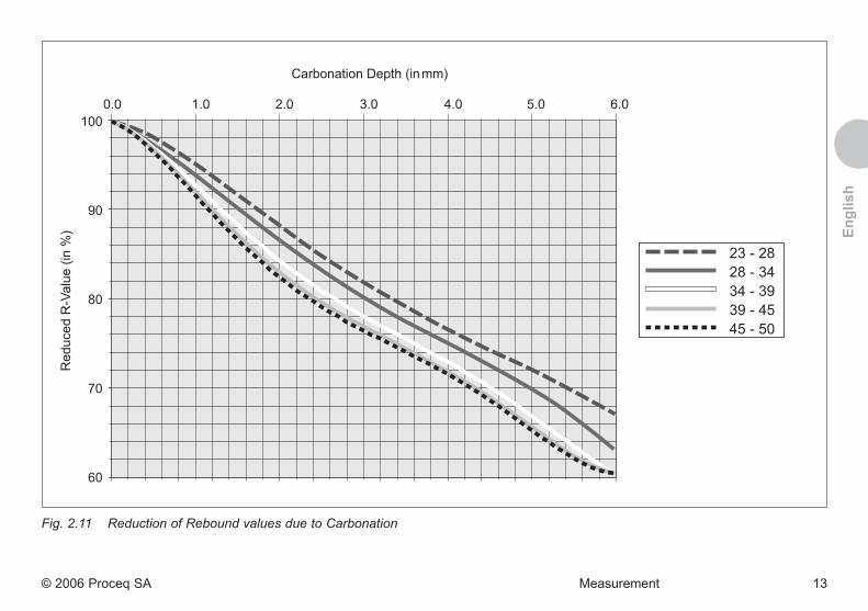
In Table A of the standard JGJ/T 23-2001, compressive strengths for rebound values from 20 to 60 (in steps of 0.2 R) and for carbonation depths from 0 to 6 mm (in steps of 0.5 mm) are shown. For carbonation depths higher than 6 mm, the values for 6 mm apply (no further changes). The values in the table are based on compre-hensive tests performed on concrete of different places of origin and of different ages.
Based on Table A, Proceq has developed reduction curves as a function of rebound value and carbonation depth. These factors can now be applied to the Proceq-curves and the curves of chapter 2.4.3.Rebound values may be reduced by up to 40%.
The curves shown in Fig. 2.11, are exclusively valid for the ORIGINAL SCHMIDT and DIGI SCHMIDT concrete test hammers from Proceq SA.
12 Measurement © 2006 Proceq SA
23 - 2828 - 3434 - 3939 - 4545 - 50
0.0 1.0 2.0 3.0 4.0 5.0 6.0100
90
80
70
60
Fig.2.11 ReductionofReboundvaluesduetoCarbonation
© 2006 Proceq SA Measurement 13
Carbonation Depth (in mm)R
educ
ed R
-Val
ue (i
n %
) Engl
ish

14 Measurement © 2006 Proceq SA
2 .5 .4 Special CasesExperience has shown that deviations from the normal con- version curves occur under the following circumstances:- Artificial stone products with an unusual concrete com-
position and small dimensions. It is recommended that a separate series of tests should be performed for each product in order to determine the relationship between the rebound value R and the compressive strength.
- Aggregates made from low strength, lightweight or clea-vable stone (e.g. pumice, brick rubble, gneiss) result in a strength value lower than shown on the conversion curve.
- Gravel with extremely smooth, polished surfaces and a spherical shape results in values for compressive strength which are lower than those ascertained by the rebound measurements.
- A strong, dry mixed concrete (i.e. with low sand content) which has not been placed adequately processed may contain lumps of gravel which are not visible from the surface. These affect the strength of the concrete with-out however influencing the rebound values R.
- The concrete test hammer gives inadequate rebound values R on concrete from which the form has just been removed, which is wet or which has hardened under water. The concrete must be dried before the test.
- Very high values for compressive strength (> 70 N/mm2) can be achieved by adding pulverized fuel ash or sili-ca fume. However, these strengths cannot reliably be ascertained using the rebound value R measured by the concrete test hammer.
2 .5 .5 Conversion Curves for Special CasesThe recommended course in special cases is to prepare a separate conversion curve.• Clamp the sample in a pressure testing machine and
apply a preload of about 40 kN vertically to the direc-tion in which the concrete had been poured in.
• Measure the rebound hardness by applying as many test impacts as possible to the sides.
The only way to achieve a meaningful result is to mea-sure the rebound values R and the compressive strength of several samples. Concreteisaveryinhomogeneousmaterial.
Samplesmadefromthesamebatchofcon- creteandstoredtogethercanrevealdiscre- panciesof±15%whentestedinthepressure testingmachine.• Discard the lowest and highest values and calculate
the average Rm.• Determine the compressive strength of the sample
using the pressure testing machine and ascertain the average value fckm.
The pair of values Rm / fckm applies to a certain range of the measured rebound value R.
It is necessary to test samples of differing qualities and / or ages in order to prepare a new conversion curve for the entire range of rebound values from R = 20 to R = 55.• Determine the curve with the pairs of values Rm / fckm
(e.g. EXCEL in the RGP function).

Engl
ish
© 2006 Proceq SA Maintenance 15
3 Maintenance3 .1 Performance CheckIf possible, carry out the performance check every time before you use the device, however at least every 1000 impacts or every 3 months.
• Place the testing anvil on a hard, smooth surface ( e.g. stone floor ). • Clean the contact surfaces of the anvil and the impact plunger. • Perform about 10 impacts with the concrete test ham- mer and check the result against the calibration value specified on the testing anvil.
Fig.3.1 Performancecheckoftheconcretetest hammer(modelN/Lshown)
Proceedasdescribedin"Maintenance Procedure"onpage16ifthevaluesarenot withinthetolerancerangespecifiedonthe testinganvil.
3 .2 Cleaning After Use Warning! Neverimmersethedeviceinwaterorwash
itunderarunningtap!Donotuseeither abrasivesorsolventsforcleaning!
• Deploy the impact plunger (1) as described in Fig. 3.2 "Measuring Procedure", on page 4.
• Wipe the impact plunger (1) and housing (3) using a clean cloth.
3 .3 Fitting a New Recording Paper Roll Thefollowinginstructionsonlyapplyto
modelsNRandLR!
31
33
32Fig.3.2 Fittinganewrecordingpaperroll
16 Maintenance © 2006 Proceq SA
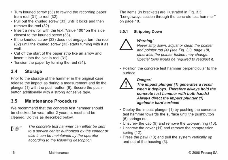
• Turn knurled screw (33) to rewind the recording paper from reel (31) to reel (32).
• Pull out the knurled screw (33) until it locks and then remove the reel (32).
• Insert a new roll with the text "Value 100" on the side closest to the knurled screw (33).
• If the knurled screw (33) does not engage, turn the reel (32) until the knurled screw (33) starts turning with it as well.
• Cut off the start of the paper strip like an arrow and insert it into the slot in reel (31).
• Tension the paper by turning the reel (31).
3 .4 StoragePrior to the storage of the hammer in the original case release the impact as during a measurement and fix the plunger (1) with the push-button (6). Secure the push-button additionally with a strong adhesive tape.
3 .5 Maintenance ProcedureWe recommend that the concrete test hammer shouldbe checked for wear after 2 years at most and be cleaned. Do this as described below.
Theconcretetesthammercaneitherbesent toaservicecenterauthorizedbythevendoror
elseitcanbemaintainedbytheoperator accordingtothefollowingdescription.
The items (in brackets) are illustrated in Fig. 3.3, "Lengthways section through the concrete test hammer" on page 18.
3 .5 .1 Stripping Down
Warning! Neverstripdown,adjustorcleanthepointer andpointerrod(4)(seeFig.3.3,page18), otherwisethepointerfrictionmaychange. Specialtoolswouldberequiredtoreadjustit.
• Position the concrete test hammer perpendicular to the surface.
Danger! Theimpactplunger(1)generatesarecoil whenitdeploys.Thereforealwaysholdthe concretetesthammerwithbothhands! Alwaysdirecttheimpactplunger(1) againstahardsurface!
• Deploy the impact plunger (1) by pushing the concrete test hammer towards the surface until the pushbutton (6) springs out.
• Unscrew the cap (9) and remove the two-part ring (10).• Unscrew the cover (11) and remove the compression
spring (12).• Press the pawl (13) and pull the system vertically up
and out of the housing (3).

Engl
ish
© 2006 Proceq SA Maintenance 17
• Lightly strike the impact plunger (1) with the hammer mass (14) to release the impact plunger (1) from the hammer guide bar (7). The retaining spring (15) comes free.
• Pull the hammer mass (14) off the hammer guide bar together with the impact spring (16) and sleeve (17).
• Remove the felt ring (18) from the cap (9).
3 .5 .2 Cleaning• Immerse all parts except for the housing (3) in kero-
sene and clean them using a brush.• Use a round brush ( copper bristles ) to clean the hole
in the impact plunger (1) and in the hammer mass (14) thoroughly.
• Let the fluid drip off the parts and then rub them dry with a clean, dry cloth.
• Use a clean, dry cloth to clean the inside and outside of the housing (3).
3 .5 .3 Assembly• Before assembling the hammer guide bar (7), lubricate
it slightly with a low viscosity oil ( one or two drops is ample; viscosity ISO 22, e.g. Shell Tellus Oil 22 ).
• Insert a new felt ring (18) into the cap (9).• Apply a small amount of grease to the screw head of
the screw (20).• Slide the hammer guide bar (7) through the hammer
mass (14).
• Insert the retaining spring (15) into the hole in the impact plunger (1).
• Slide the hammer guide bar (7) into the hole in the impact plunger (1) and push it further in until noticeable resistance is encountered.
Priortoandduringinstallationofthesystem inthehousing(3),makesurethattheham-
mer(14)doesnotgetheldbythepawl(13). Hint:Forthispurposepresspawl(13)briefly.
• Install the system vertically downwards in the housing (3).
• Insert the compression spring (12) and screw the rear cover (11) into the housing (3).
• Insert the two - part ring (10) into the groove in the sleeve (17) and screw on the cap (9).
• Carry out a performance check.
Sendinthedeviceforrepairifthemainte- nanceyouperformdoesnotresultincorrect
functionandachievementofthecalibration valuesspecifiedonthetestinganvil.
18 Maintenance © 2006 Proceq SA
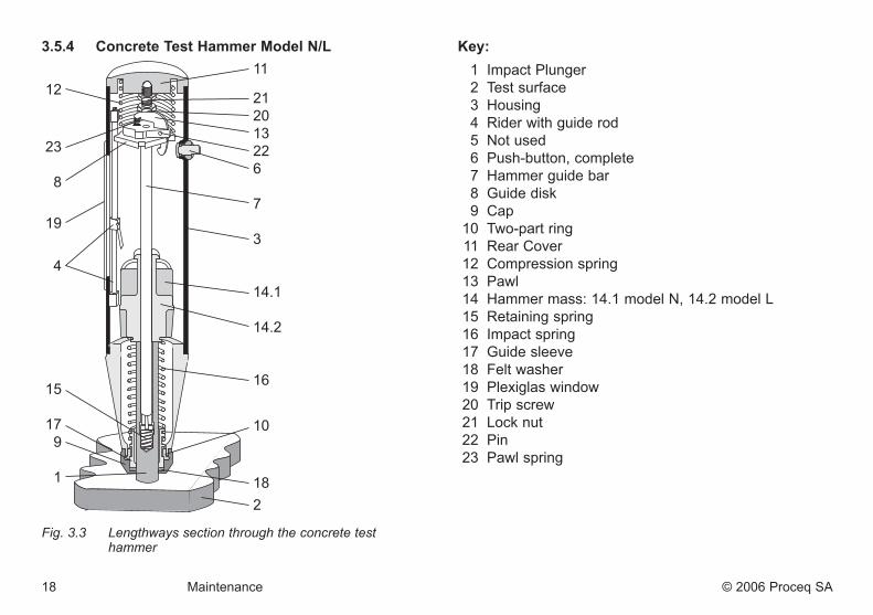
3 .5 .4 Concrete Test Hammer Model N/L
Fig.3.3 Lengthwayssectionthroughtheconcretetest hammer
Key: 1 Impact Plunger 2 Test surface 3 Housing 4 Rider with guide rod 5 Not used 6 Push-button, complete 7 Hammer guide bar 8 Guide disk 9 Cap 10 Two-part ring 11 Rear Cover 12 Compression spring 13 Pawl 14 Hammer mass: 14.1 model N, 14.2 model L 15 Retaining spring 16 Impact spring 17 Guide sleeve 18 Felt washer 19 Plexiglas window 20 Trip screw 21 Lock nut 22 Pin 23 Pawl spring

Engl
ish
© 2006 Proceq SA Data 19
4 Data
4 .1 Form of Delivery
Concrete test hammer Model N Model NR Model L Model LRArticle-no. 310 01 000 310 02 000 310 03 000 310 04 000Total weight 1.7 kg 2.6 kg 1.4 kg 2.4 kgCarrying case, W x H x D 325 x 125 x 140 mm 325 x 295 x 105 mm 325 x 125 x 140 mm 325 x 295 x 105 mmGrindstone 1 pce. 1 pce. 1 pce. 1 pce.Recording paper – 3 rolls – 3 rolls
4 .2 Accessories
Concrete test hammer Model N Model NR Model L Model LRAccessory article number
Testing anvil 310 09 000 310 09 000 310 09 000 310 09 000Recording paper, pack of 5 rolls – 310 99 072 – 310 99 072
4 .3 Tecnical Data
Concrete test hammer Model N Model NR Model L Model LRImpact energy 2.207 Nm 0.735 NmMeasuring range 10 bis 70 N/mm2 compressive strength 10 bis 70 N/mm2 compressive strength