Embed Size (px)
Citation preview

P a g e | 1
www.ammhu.com A categorized blogging website and an Online Resource Centre For CBSE, RBSE, and Other State Boards — Raj Kumar Parashari, Head Science @ JPHS, Jaipur-302021
SCHOOL NAME SCHOOL NAME SCHOOL NAME
ADDRESS WITH PINCODE AND PHONE NUMBER
Submitted by Guided by
Student Name [ Teacher Name ]
XII Sc ……
Board Roll No. Designation
-----------

P a g e | 2
www.ammhu.com A categorized blogging website and an Online Resource Centre For CBSE, RBSE, and Other State Boards — Raj Kumar Parashari, Head Science @ JPHS, Jaipur-302021
INDEX
I. Certificate
II. Acknowledgement
1. Aim/ Objective
2. Apparatus Required
3. Theory
4. Experimental Demonstration of Diffraction
5. Experimental Set up & Procedure
6. Observations
7. Calculations
8. Result
9. Precautions
10. Bibliography

P a g e | 3
www.ammhu.com A categorized blogging website and an Online Resource Centre For CBSE, RBSE, and Other State Boards — Raj Kumar Parashari, Head Science @ JPHS, Jaipur-302021
CERTIFICATE
This is to certify that _______________________ student of
______ school name _______, class XII Sc __ has carried out
his work for the investigatory project entitled
_______________________________________ under my guidance
and supervision.
Signature of the Teacher
Name Of The Teacher
Designation

P a g e | 4
www.ammhu.com A categorized blogging website and an Online Resource Centre For CBSE, RBSE, and Other State Boards — Raj Kumar Parashari, Head Science @ JPHS, Jaipur-302021
ACKNOWLEDGEMENT
I __________________________________ a student of
____________________________________,______________ would like to pay
my sincere gratitude to my Physics teacher Mr./Mrs.
__________________________ for helping and guiding me throughout
the completion of the project report. I would like to thank
Mr./Mrs. _______________________ our school principal/Director
for making school such a wonderful place of learning. I also
would like to thank Mr. ______________ our lab assistant for the
timely assistant in completion of the project.

P a g e | 5
www.ammhu.com A categorized blogging website and an Online Resource Centre For CBSE, RBSE, and Other State Boards — Raj Kumar Parashari, Head Science @ JPHS, Jaipur-302021
1. AIM Determination Of Wavelength of Laser Light Beam By Observing
Diffraction Through Single Slit
2. APPARATUS REQUIRED A Helium-Neon Leaser, A single slit , A Meter scale, A Travelling
microscope and a screen (a white wall with a graph paper pasted on it
can serve as a good screen.)
3. THEORY The phenomenon of bending of light around the corners of small
obstacles or apertures and its consequent spreading into the regions of
geometrical shadow is called diffraction of light. It is prominent when
wavelength of incident light is of the order of size of aperture or obstacle.
Diffraction of light at a single slit : Consider a plane wavefront
WW' of monochromatic light incident normally on a narrow rectangular
slit AB. According to Huygens' theory, all parts of the slit AB will become
source of secondary wavelets, which all start in the same phase. These
secondary wavelets spread out in all directions and superposes to
produce diffraction pattern, which is focused by a convex lens L2 on a
screen placed in its focal plane.

P a g e | 6
www.ammhu.com A categorized blogging website and an Online Resource Centre For CBSE, RBSE, and Other State Boards — Raj Kumar Parashari, Head Science @ JPHS, Jaipur-302021
The secondary wavelets originated from the and of wavefront (A, B)
produces zero path difference or zero phase difference on reaching point
O (Point O lies at the perpendicular bisector of line joining A and B) and
hence superpose constructively to produce bright region. Same argument
for all the pair of sources such as (A1, B1), (A2, B2) and shown thus we
get central maxima at point O.
Positions of secondary minima : Let the point P be the point
where first secondary minima in located. Position of first secondary
minima could be explained provided path difference between waves
emitted from the ends of wave front .
Let us divide the wave front into two halves AC and CB then the path
difference between the wavelets from any two corresponding points of
AC and CB will be /2. These wavelets add up destructively to produce a
minimum, so does effect of all pair of sources such as (A1, C1), (A2, C2),
.........

P a g e | 7
www.ammhu.com A categorized blogging website and an Online Resource Centre For CBSE, RBSE, and Other State Boards — Raj Kumar Parashari, Head Science @ JPHS, Jaipur-302021
Thus the condition for first secondary minima is
or BP – AP =
or a sin 1 =
The condition for nth dark fringe can be written as
a sin n = n , where n = 1, 2, 3,...
Positions of secondary maxima : Let the point P be the point
where first secondary maxima is located. Position of first secondary maxima could
be explained provided path difference between waves emitted from the ends of
wave front = 3 / 2 .
Let us divide the wave front into three halves AC, CD and DB then the path
difference between the wavelets from any two corresponding points of AC and CD
will be /2. These wavelets add up destructively to produce a minimum, so does is
effect of all pair of sources such as (A1, C1), (A2, C2), ......... Thus effect of AC part of
wave front is canceled by CD part of the wave front. All the secondary wave
originated from DB part of the wave front meet at point P and superpose
constructively and we get first secondary maxima.
Thus the condition for first secondary maxima is
or BP – AP = 3 / 2
or a sin 1 = 3 / 2
The condition for nth secondary maxima can be written as
na sin ' ( 2n 1) ,2
n = 1, 2, 3, ......
The intensity of secondary maxima decreases as n increases.

P a g e | 8
www.ammhu.com A categorized blogging website and an Online Resource Centre For CBSE, RBSE, and Other State Boards — Raj Kumar Parashari, Head Science @ JPHS, Jaipur-302021
(b) Width of central maxima is equal to separation between first secondary
minima on either side of central maxima.
Thus W = 2 x1
For first secondary minima
a sin 1 =
or,
1xa
D
or, 1
Dx
a
So , 1
2 DW 2x
a
Which is the required the formula for the width of central maxima
Note:- Angular width of central maxima, It is the angle made by width of
central maxima at the centre of slit. It is given by
W 22
D a
and it does not depend upon ‘D’ i.e. distance of the screen from the slit.

P a g e | 9
www.ammhu.com A categorized blogging website and an Online Resource Centre For CBSE, RBSE, and Other State Boards — Raj Kumar Parashari, Head Science @ JPHS, Jaipur-302021
(c) The variation of intensity with phase difference in a single slit diffraction
experiment.
4. EXPERIMENTAL DEMONSTRATION OF DIFFRACTION
PATTERN
i). Procure a special electronic bulb with a single straight filament. This bulb with
single straight filament can serve as a line source for all particle purposes.
ii). Paste a thin sheet of tin foil on a glass plate & cut a thin slit by means of sharp
needle or a blade.
iii). Cover the electric lamp with an enclose made of glass (red) or transparent red
sheet which acts as a filter for transmitting only red light.
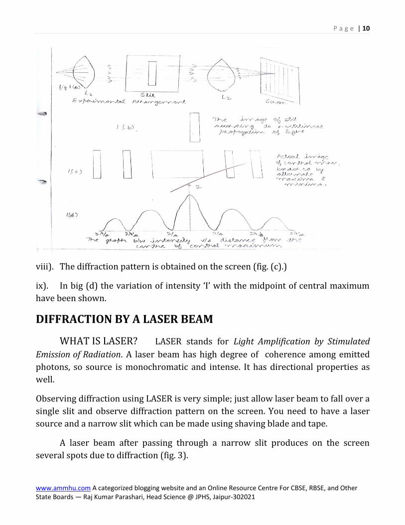
iv). Arrange the slit ‘s’ and the screen as shown in fig. (a). A convex lens '' 1L should
be placed before the line of source in such a way that the line source lies at the
principle focus of lens '' 1L . In this position convex lens forms the image of the line of
source at infinity and ray coming from the source at infinity form a parallel beam of
light. These parallel rays fall on the slit ‘s’.
v). Parallel rays of light on passing through the slit ‘s’ diverge out. These
diverging rays are focused on the screen by another lens 2L shown in fig. (a).
vi). On the screen diffraction pattern is observed. It consist of central maximum
surrounded by alternate minima and maxima of varying intensity.
vii). The geometrical image of the slit which in present case is equal to the width of
the slit (in fig. (b)).
P a g e | 10
www.ammhu.com A categorized blogging website and an Online Resource Centre For CBSE, RBSE, and Other State Boards — Raj Kumar Parashari, Head Science @ JPHS, Jaipur-302021
viii). The diffraction pattern is obtained on the screen (fig. (c).)
ix). In big (d) the variation of intensity ‘I’ with the midpoint of central maximum
have been shown.
DIFFRACTION BY A LASER BEAM
WHAT IS LASER? LASER stands for Light Amplification by Stimulated
Emission of Radiation. A laser beam has high degree of coherence among emitted
photons, so source is monochromatic and intense. It has directional properties as
well.
Observing diffraction using LASER is very simple; just allow laser beam to fall over a
single slit and observe diffraction pattern on the screen. You need to have a laser
source and a narrow slit which can be made using shaving blade and tape.
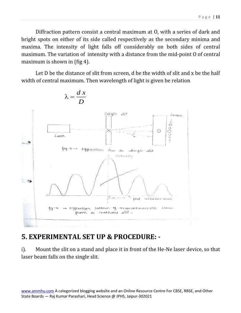
A laser beam after passing through a narrow slit produces on the screen
several spots due to diffraction (fig. 3).
P a g e | 11
www.ammhu.com A categorized blogging website and an Online Resource Centre For CBSE, RBSE, and Other State Boards — Raj Kumar Parashari, Head Science @ JPHS, Jaipur-302021
Diffraction pattern consist a central maximum at O, with a series of dark and
bright spots on either of its side called respectively as the secondary minima and
maxima. The intensity of light falls off considerably on both sides of central
maximum. The variation of intensity with a distance from the mid-point O of central
maximum is shown in (fig 4).
Let D be the distance of slit from screen, d be the width of slit and x be the half
width of central maximum. Then wavelength of light is given be relation
d x
D
5. EXPERIMENTAL SET UP & PROCEDURE: -
i). Mount the slit on a stand and place it in front of the He-Ne laser device, so that
laser beam falls on the single slit.

P a g e | 12
www.ammhu.com A categorized blogging website and an Online Resource Centre For CBSE, RBSE, and Other State Boards — Raj Kumar Parashari, Head Science @ JPHS, Jaipur-302021
ii). View the diffraction pattern on white wall situated suitably long distance
away from the slit. A graph is pasted on the wall at the place where diffraction
pattern is expected to be obtained.
iii). Adjust the height and portion of the slit in front of the laser beam so that a
good diffraction pattern with distinct maxima and minima obtained on the wall.
iv). Measure ‘x’ distance between mid-point of central maximum and mid-point of
first minimum with the help of graph paper. Measure ‘x’ on both sides of central
maximum and take the mean of two readings.
v). Measure the distance between the slit and the screen (i.e. wall) with the help
of a meter scale & thread.
vi). Measure the slit width‘d’ with travelling microscope.
vii). Take several readings by changing D & d.
6. OBSERVATIONS
Reading of
microscope at the
lower edge x1 cm
Reading of
microscope at the
lower edge x2 cm
12 xxd (cm)
Slit 1
1.
9.50 + 0.042 = 9.542
9.55 + 0.022 = 9.572
9.572 - 9.542 = 0.030
Slit 2
2.
9.45 + 0.031 = 9.481
9.50 + 0.006 = 9.506
9.506 – 9.481 = 0.025
(b) Half linear width of central maxima (x) & Wavelength of
Laser Beam

P a g e | 13
www.ammhu.com A categorized blogging website and an Online Resource Centre For CBSE, RBSE, and Other State Boards — Raj Kumar Parashari, Head Science @ JPHS, Jaipur-302021

P a g e | 14
www.ammhu.com A categorized blogging website and an Online Resource Centre For CBSE, RBSE, and Other State Boards — Raj Kumar Parashari, Head Science @ JPHS, Jaipur-302021
S. No.
Slit Width d (cm)
Distance of screen from slits D (cm)
Half linear width x (cm)
Wavelength of lightxd / D
1. 0.030 cm 300 cm 1 3 2 0 65. / . cm 56 500 10. cm
2. 0.030 cm 200 cm 0 9 2 45. . / . cm 56 750 10.
3. 0.025 cm 300 cm 1 6 2 0 80. / . cm 510667.6
4. 0.025 cm 200 cm 1 1 2 0 55. / . cm 56 875 10.
7. CALCULATION S
x.d / D
5
1
0 65 0 036 500 10
300
. .. cm
, 5
2
0 45 0 036 750 10
200
. .. cm
5
3
0 80 0 0256 667 10
300
. .. cm
, 5
4
0 55 0 0256 875 10
200
. .. cm

P a g e | 15
www.ammhu.com A categorized blogging website and an Online Resource Centre For CBSE, RBSE, and Other State Boards — Raj Kumar Parashari, Head Science @ JPHS, Jaipur-302021
1 2 3 4
4mean
A
m
cm
6698
106698
10698.6
10
5
8. RESULT
The mean wavelength of light source is 6698 A°.
9. PRECAUTIONS
1. The slit should be sufficiently narrow to obtain a good diffraction pattern.
2. Slit width should be measured with a travelling microscope after finding its least count ( usually it is 0.01mm).
3. x should be measured accurately on a graph paper by counting its square properly.
4. Don’t look into the laser beam directly. It can damage your eye.
10. BIBLIOGRAPHY
1. CBSE Compendium
2. NCERT
3. University Physics.
4. Concepts Of Physics by by H.C. Verma

P a g e | 16
www.ammhu.com A categorized blogging website and an Online Resource Centre For CBSE, RBSE, and Other State Boards — Raj Kumar Parashari, Head Science @ JPHS, Jaipur-302021
1. Note: — You need to have your own observation graph
sheets. Values for half linear width and slit width of different
students can be different
Note: — Hand written Investigatory Project Report should be
submitted. Work should be neat and clean. Avoid unnecessary
fancy decoration of the project report.
Note: — Learn theory, working and related viva for board
practical examination.
Wish you all the best.
Raj Kumar Parashari
Head Science , JPHS, Jaipur