Embed Size (px)
Citation preview
School of Chemical Technology
Master's Programme in Bioproduct Technology
Gaurav Das
SYNTHESIS AND CHARACTERIZATION OF ZEOLITE FROM WASTE
COAL FLYASH FOR TAILORED APPLICATION IN BIOREFINING AND
PROCESS WATER CLEANING: AN INNOVATIVE APPROACH
TOWARDS A CLEANER CIRCULAR ECONOMY
Master’s thesis for the degree of Master of Science in Technology
submitted for inspection, Espoo, 30 April, 2016.
Supervisor Professor Eero Kontturi
Aalto University, P.O. BOX 11000, 00076 AALTO
www.aalto.fi
Abstract of master's thesis
Author Gaurav Das
Title of thesis Synthesis and characterization of zeolite from waste coal flyash for tailored appli-
cation in biorefining and process water cleaning: An innovative approach towards a cleaner cir-
cular economy
Department Forest Products Technology
Professorship Bio-based materials Code of professorship 10220
Thesis supervisor Professor Eero Kontturi
Thesis advisor M.Sc (Tech) Bob Talling
Date 30.04.2016 Number of pages 90 Language English
Abstract
The purpose of the investigation was to assess if Finnish coal flyash (CFA) waste could be used to syn-
thesize zeolites. The world produces 750 million tonnes of CFA annually which is also the largest
quantity waste produced. This figure will only increase as India, China, South America and Africa
charges ahead with industrialization. The global recycle rate is 15% annually. Finland produces about
750,000 tonnes of CFA per year. It is also estimated that millions of tonnes of CFA is backfilled glob-
ally. Hence there is great potential to use it for high value applications as the raw material security
exists. There are also disposal and environmental issues related to CFA which makes it our obligation
to find a great solution. The recent trend towards circular economy, waste to value, sustainability, EU
and National environmental legislations also provides a great platform to find a solution. Other rea-
sons have been analysed from engineering, policy making, markets, scientific & innovation, national
and regional impact, international trade, geographic location and future study perspectives.
The literature section provides insights into CFA, structure, transformation, mechanism, combustion
process, applications, environmental issues etc. The Zeolite section gives a deep understanding of
origin, history, classification, trends in development, structure, morphology, applications, properties,
circular economy context of zeolites, synthesis methods, raw material variations etc. There are 174
zeolite framework types in zeolite families and we put special emphasis on NaX (Faujasite framework)
with tailored descriptions. The literature highlights CFA Zeolites, its differences with pure chemical
ones, synthesis methods, previous works and global pilot projects.
Conversion of Finnish CFA to Zeolite was a grand success. The overall process involved sieving, batch
preparation, ageing, hydrothermal treatment, washing/filtration, drying and grinding. We sieved CFA
to collect unburnt carbon (0.2% weight basis) and obtain consistent particle range. Creation of appro-priate chemical composition, ageing for 24 hours (650 rpm at 21℃), hydrothermal treatment for 24
hours at 60℃-85℃. Washing is followed by drying the product for 16h and grinding it with mortar
and pestle. CFA Zeolites have been made for the first time in Finland and Northern Europe.
Both the CFA and CFA Zeolites were analysed using XRD, EDX, SEM and BET. CFA consisted of
amorphous SiO2 and Al2O3 along with crystalline quartz (SiO2) and mullite (SiO2.Al2O3). The LOI
was 4.57% (weight basis). The BET value for CFA was 366. 73 m2/g. The CFA Zeolite was pure phase
NaX and crystalline without competing GIS, SOD, LTA phases. The BET surface area of CFA Zeolite
was approx. 1800-2000 m2/g. This is the first time such high values have been reported in the world.
The process was scaled up from lab to bench scales. Various repetitive tests were conducted in lab and
bench scales to have consistent results. Statistical analysis was conducted to obtain quality control
guidelines.
Keywords Coal fly Ash (CFA), Zeolite, NaX, Circular economy, alkaline activation, geopolymers

ACKNOWLEDGEMENT
The thesis has been carried out with support of various entities such as Aalto
University, Aalto University Department of Forest Products Technology,
Research Organizations, Foundations and Experts. All the entities have been
thanked individually for their kind contributions.
My special thanks goes to my supervising professor and industry experts for their
encouragement, cooperation and support in various forms. I would also like to
thank all laboratory staff of Department of Forest Products Technology and
School of Chemical Technology.
Last but not the least I would like to thank my family and loved ones for their
support.
Helsinki, Finland 30.04.2016

CONTENTS
1 INTRODUCTION .............................................................................................. 7
1.1 Background ................................................................................................... 7
1.2 Objectives ...................................................................................................... 9
1.3 Thesis outline ................................................................................................ 9
1.4 Significance of study ................................................................................... 10
1.5 Highlights and achievements ...................................................................... 10
2 LITERATURE REVIEW ................................................................................ 12
2.1 Coal Fly Ash ............................................................................................... 12
2.1.1 Introduction .......................................................................................... 12
2.1.2 Mineralogy and Chemistry ................................................................... 12
2.1.3 Environmental problems and disposal ................................................. 15
2.1.4 Application ........................................................................................... 17
2.2 Zeolite ......................................................................................................... 18
2.2.1 Introduction .......................................................................................... 18
2.2.2 Classification of zeolites ...................................................................... 19
2.2.3 Zeolite Framework ............................................................................... 20
2.2.3 Framework type FAU .......................................................................... 23
2.2.4 Zeolite precursors ................................................................................. 27
2.2.5 Synthesis techniques ............................................................................ 28
2.2.6 CFA Zeolite .......................................................................................... 33
2.3 Zeolite properties and applications ............................................................. 35
2.3.1 Cation Exchange .................................................................................. 35
2.3.2 Dessication ........................................................................................... 35
2.3.3 Water softening .................................................................................... 36

2.3.4 Anion absorption .................................................................................. 36
2.3.5 Molecular sieves................................................................................... 37
2.3.6 Hydrocarbon separation ....................................................................... 37
2.3.7 Medical applications ............................................................................ 37
2.3.8 Agriculture ........................................................................................... 37
2.3.9 Desulphurization operations ................................................................ 38
2.3.10 NOX Removal ..................................................................................... 38
2.3.11 Construction industry ......................................................................... 38
2.3.12 Heating systems ................................................................................. 38
2.3.13. Separation of gases ............................................................................ 39
2.3.14 Liquid separation and purification ..................................................... 39
2.3.15 Biomass upgrading and derivatives ................................................... 39
2.3.16 Geotechnical Applications ................................................................. 40
2.4 Circular economy ........................................................................................ 40
2.4.1 Introduction .......................................................................................... 40
2.4.2 The current situation ............................................................................ 41
2.4.3 Basic concepts and perspectives .......................................................... 41
2.4.4 Key trends and new perspectives ......................................................... 42
2.4.5 Policy making initiatives for circular economy in various countries ... 43
2.4.6 Circular economy aspect in CFA Zeolite production and application . 45
3 EXPERIMENTAL ........................................................................................... 47
3.1 Coal Flyash ................................................................................................. 47
3.1.1 Pre-treatment ........................................................................................ 47
3.2 Zeolite ......................................................................................................... 48
3.2.1 Synthesis process ................................................................................. 48
3.3 Chemical composition and EDX analysis ................................................... 49

3.1.3 SEM Analysis .......................................................................................... 50
3.1.4 XRD Analysis .......................................................................................... 50
3.1.5 BET Analysis ........................................................................................... 50
3.2.6 Statistical Analysis ................................................................................... 50
4 RESULTS AND DISCUSSION ...................................................................... 53
4.1 Coal Flyash ................................................................................................. 53
4.1.1 Pre-treatment ........................................................................................ 53
4.1.2 Chemical composition and EDX analysis ............................................ 56
4.1.3 SEM Analysis ...................................................................................... 58
4.1.4 XRD Analysis ...................................................................................... 63
4.1.5 BET Analysis ....................................................................................... 63
4.2 Zeolite ......................................................................................................... 64
4.2.1 Zeolite Synthesis process ..................................................................... 64
4.2.2 XRD Analysis ...................................................................................... 68
4.2.3 BET Analysis ....................................................................................... 69
4.2.4 SEM Analysis ...................................................................................... 72
4.2.5 Chemical composition and EDX analysis ............................................ 77
4.2.6 Statistical Analysis ............................................................................... 78
5 CONCLUSIONS .............................................................................................. 80
6 FUTURE WORK ............................................................................................. 82
REFERENCES .................................................................................................... 82

7
1 INTRODUCTION
1.1 Background
The backbone of modern civilization and industry is based on thermal power, heat
and energy in various forms. The energy industry is by far the biggest in the world.
In the energy industry, coal powered thermal plants is one of the major players. It
is also one of the major polluters in the world. As in any chemical industry there
are multiple polluting items and agents hence cannot be generalized. In light of that
the key polluting waste generated in thermal power plant is identified as coal flyash
(CFA)[1].
The coal powered thermal power industry produces 750 million tonnes of CFA
globally on an annually basis[2]. India alone produces 112 million tonnes of
CFA/annum as of 2012[3].This figure will only grow in the next years as India,
China, Africa and South America charges ahead in industrialization. Their growing
economies will need huge amount of electricity to power their new factories,
growing middle class and ambitious infrastructure projects. As coal is available in
abundance in those regions[4], it is certain that coal power plants will provide the
majority of growing energy needs. Growth and prosperity is the key focus in driving
legislation in those regions hence it may or may not have the strictest norms when
it comes to coal and CFA related issues. Therefore prohibiting the use of coal
powered plants from a global context is not feasible. In such a circumstance the
practical solution would be to find multiple applications for CFA. In terms of
quantity alone it poses a massive challenge in disposal, recycle, storage, reuse and
environmental pollution[5]. The global recycling rate of CFA is 15%[6]. Germany
produces 40 million tonnes/annum of CFA [3].
Finland is a highly industrialized country with high emphasis on innovation. The
chemical industry in Finland is quite significant and combined with the fact that it
is in situated in a cold region creates a huge demand for heat, electricity and power.
Finland has a lot of coal based power plants all over the country. The annual
production of CFA is estimated to be 750,000 tonnes[7]. One of the largest plants
to produce CFA is in Kristinakaupunki in the west coast of Finland with annual
8
production of 119,000 tonnes. The Uusimaa region in southern Finland is a major
hotbed of industry, innovation and population. To keep up with the high demand of
energy there are multiple energy generation sources but we will focus on coal based
power plants. In this context especially Helsinki and Espoo has many coal power
plants. The combined production capacity of CFA is anywhere between 75,000-
150,000 tonnes/annum. The Salmisaari and Suomenoja power plants in Helsinki
region alone have a combined capacity of 65,000-75,000 tonnes/annum[7]. It is
evident that all of the CFA is not used and part of it remains. Moreover, we need to
factor that there is already couple of million tonnes of CFA stored in silos and
landfills. The sheer quantity makes CFA a challenge and an opportunity. From our
perspective it is viewed as secure raw material source for any large scale application
for couple of decades to come. Hence given the national, EU legislative and
environmental obligations at hand we have to find an appropriate solution.
Conversion of CFA to zeolite is an answer to that and an opportunity in disguise.
Zeolite is an extremely versatile material. They are microporous aluminosilicates
used especially as absorbents and catalysts. It has a wide range of applications in
all sectors of the chemical industry in various forms. It can be used in powder,
pellet, membrane, thin film and other forms. More about the uses is discussed in the
applications sections later. The prices of zeolite vary from 1,000 Euros/tonne-
20,000 Euros/tonne based on purity and application[8]. Hence it is evident that
producing zeolites could bring higher economic benefits compared to other uses of
CFA. Moreover zeolites have high regeneration rates which makes it even more
versatile.
The conversion of CFA to zeolite is among the most viable routes when dealing
with waste as raw materials. This idea is in our vision and motivation of “clean
wastes by waste”. This is further in support of the recent trend towards development
of a circular economy. In this trend wastes are considered as valuable materials
towards development of products vital for other operations in the same or different
industry.
Development of new innovative technology strategy to address industrial wastes
problem in Finland to meet national and EU Horizon 2020 environmental mandates

9
and directives. As of now Finnish industries have not developed adsorbents, ion-
exchangers from waste materials such as CFA to be used in other equally valuable
operations. This is in line with present trend of an innovative circular economy.
The real challenge is to meet the stringent zeolite type specifications especially
when waste raw material such as coal fly ash is used, but that is where the
innovative nature of the thesis lies.
1.2 Objectives
The objective of this thesis is:
To determine the suitability of Finnish CFA for synthesis of any zeolite.
Conversion of waste coal flyash ash into appropriate zeolite. In our case we
would develop FAU type framework zeolite namely NaX. Hence it is
development of a product.
Development of a cost effective synthesis method to develop zeolites tailor
made to be used as adsorbents for waste water treatment, ion-exchangers.
Hence it is development of a process.
Characterization and analysis of Coal flyash and final product i.e. zeolites
using XRD, SEM, EDX, BET.
The technology so developed would be based on the idea that they are
simple, easy to implement, cost effective, industrially scalable and
replicable elsewhere.
To reinforce the theme of circular economy, ideas will be generated and
implemented along the lines of thesis so that there is maximum resource
valorisation.
1.3 Thesis outline
The core focus of the thesis is on zeolites, circular economy and sustainability.
The initial part of the thesis describes about the background. It mainly emphasises
about CFA production and disposal problems at a global and national level. The
10
need and economic benefits for the approach is also justified. The literature review
greatly emphasizes CFA, Zeolites, CFA Zeolites, Zeolite applications, Circular
economy, Context of circular economy in CFA Zeolite concept, legislation, policy
making, current and future industrial trends, markets etc. The later part of the thesis
emphasizes on CFA assessment, CFA Zeolite synthesis process, excellent results
and its global implications. It greatly emphasises the prospect of industrial
scalability by means of pilot plant as the technical, logistical and business concerns
have been addressed. Hence the thesis addresses the topic from various
perspectives.
1.4 Significance of study
This kind of R&D work solidifies Finland’s high ranking in cleantech sector in
Scandinavia, Europe and globally. CFA Zeolite is being invented for the first time
in Finland and Northern Europe. Hence there is distinctiveness of work.
Industrially relevant project involving the vast power generation industry, waste
management industry, mining and metallurgy industry and bioeconomy sectors. It
draws synergy between all of these (but not limited to) sectors. It tries to point out
how each industry’s/regional weakness can be used as food and strength for another
industry and sector. The broad ideas of using a specific type of raw materials to
make certain category of products which are applied in multiple industries to
enhance circular economy is quite significant. Hence the idea that develops synergy
between various different industries is significant. The work is based on circular
economy which is very topical at the moment.
1.5 Highlights and achievements
Coal flyash was successfully converted to FAU class NaX zeolite (new product). A
simple, cheap, scalable, easy implementation oriented process was developed (new
process). The process produced high quality NaX zeolites and in addition was
engineered to obtain heat and unburnt carbon. So instead of getting only zeolite, the
process was tuned to obtain unburnt carbon and heat as well. It is a low temperature

11
process having range of 60-90℃. The process is also quick with crystallization
period of 24h. Hence there is maximum utilization of chemistry.
The NaX zeolite is of very high quality with BET surface area of 1800-2000 m2/g.
Such high surface areas are reported for the first time in the world under the current
circumstances, processes and systems. It is a highly crystalline structure. Hence
there are creative contributions and new results.
Lab scale studies were followed by bench scale studies to give identical products
and properties. The product properties were consistent and replicable with less
margin of error during lab and bench scale respectively. Hence there is already
commitment for further development.
The work has been carried out in Helsinki and Espoo regions and to be applied in
Helsinki and Espoo regions. It highlights Helsinki and Espoo has a hub of Nordic
and global innovation. It also shows real commitments from Helsinki and Espoo
entities such as Aalto University, power generation industry and waste management
industry. It also highlights the enthusiasm of researchers who would undertake such
project which makes a better environment with good sustainability and economic
implications. The project has environmental, legislative and economic implications
relevant to Finland in EU and globally.
The zeolite has been specifically designed for adsorption in waste water treatment,
bio-refining catalysis and as controlled substance delivery agent in agriculture.
They have been tested by third party and proved promising and consistent. Hence
there is immediate practical application of research.
Results are of high importance to academia, industry, society and professionals with
commercial implications.

12
2 LITERATURE REVIEW
2.1 Coal Fly Ash
2.1.1 Introduction
Coal flyash (CFA) is produced when combustion of coal takes place for primarily
energy production. It has received attention over the last decades to find more
sustainable use. To save and optimize natural resource utilization it is essential to
use by-products generated in one industrial process into another. This approach
helps in reduction of energy and material consumption.
There are various methods of coal combustion. Depending on kind of process,
layout and type of coal, we get various kinds of coal flyashes namely fluidized bed
ash, pulverized bed ash among others. In our case we will discuss about pulverized
bed ash and utilization. CFA is produced when combustion typically takes place in
a pulverized bed at 1000-1700℃. The presence of a variety of components makes
CFA one of the most complex anthropogenic materials. As such 316 individual
minerals and 188 mineral groups have been identified in various CFAs[9].
The annual global production of CFA is 750 million tonnes. The utilization figures
are 39% in USA, 47% in Europe and global average is 15%. Moreover CFA is the
world’s largest waste produced in terms of quantity[2]. Hence a considerable
amount of CFA have to be disposed.
2.1.2 Mineralogy and Chemistry
Coal is one of the most complex natural materials consisting of organic and
inorganic constituents with various origins formed in sedimentary environment.
Inorganic components constitute a small part of coal but most of the problems
associated with coal is due to this fraction. The mineral matter of coal provide
information about possible toxic trace elements. Ultimate analysis of coal by
various researchers reveals it contains 60-80% carbon, 10-15% sulphur dry weight
basis. The inorganic minerals present are quartz (majority), muscovite, calcite,
dolomite, ankerite, hematite, gypsum, cerussite, illite, kaolinite and pyrite. There is

13
infinite variation based on coal origin, deposition and geology involved[10]. The
complex mixture undergo milling and processing before being sent for various
applications[11]. In our case they are sent to pulverized combustion boilers. The
combustion boiler designs and energy efficiencies are completely separate topics.
The phenomenon of heat, mass, momentum transfers are very complex and have
been researched and modified for more than a century. We will not go deep as it is
not our focal area. So we would limit our discussion by providing chemical equation
for simple understanding.
Coal (C +Inorganics) +O2(air) →COx+ SOx +NOx+ Inorganics (ash) +Heat (1)
Coal combustion takes place between 1200-1600℃ in boilers to produce mainly
heat, unbunt coal, carbon monoxide, carbon dioxide, oxides of nitrogen and
sulphur[12]. A large amount of inorganic residue is produced known as CFA and
bottom ash. How the CFA residues are formed is a complex topic with no clear
explanations until now[13]. There are some hypotheses but absence of concrete
answers is mainly due to difficulty in executing and monitoring structural changes
at 1500℃. But most of the hypotheses revolve around the fact that it requires very
high temperatures for formation of molten materials. The high temperatures
facilitate the particles being molten. The molten particles mix, intertwine and form
into a spherical shape so as to reduce surface tension[12]. During combustion there
is sudden cooling of the flue gas which passes from the boiler to chimney. This
sudden heating, cooling and pressure variation in a very short period of time leads
to amorphization of particles[13]. The sudden loss of pressure also facilitates the
expansion of particles. It is also thought that high melting point materials like iron
oxide retain part of their original earth shapes hence they may not be spherical in
the SEM pictures. This a very logical explanation verified by various researchers
from SEM images and other instrumental approaches[14].
The main components of CFA are glass, silica, alumina, ferrous oxide, calcium
oxides with unburn carbon (LOI). The silica and alumina components forms the
majority of constituents. CFA chemistry is largely determined by the type of coal
burned. In general CFA from sub-bituminous and lignite coals are characteristic of
higher calcium oxide with lower silica and alumina. Bituminous and lignite CFA
14
that possess less than 10% CaO in total often have aluminosilicate glass without
any crystalline components. Such a CFA could be suited for zeolite precursors [2].
In terms of minerology the CFA consists of glass, mullite, quartz, hematite-
magnetite, feldspars etc in a case by case basis. CFA also contain trace amounts of
As, Cr, Pb and Se among others. It is also to be noted that the CFA minerology and
chemistry varies depending on where it has been stored and collected in the power
plant, e.g., coal bottom ash is different from coal flyash, ash collected from hopper
is different from ash collected from elsewhere which again varies from plant to
plant having different coal and processes in place[15][16].
Quartz present in the coal is mostly unreactive but part of it undergo phase
transformation to form cristobalite (polymorph) in the combustion chamber. The
clay minerals in coal transforms to mullite and amorphous substances. The
proportion of mullite in CFA is broadly related to proportion of clay (sometime also
mica when present) in coal feedstock. Ca related to organic matter, carbonates,
gypsum and basanite present in coal reacts with aluminosilicate materials present
in clay to form anorthite. Small quantities of Ca-aluminosilicates such as gehlenite,
diopside etc are also formed. The Ca not taken up by aluminosilicates forms
anhydrite and portlandite and rest integrated in an amorphous mix. Anhydrite forms
by interaction of Ca and SO2 variations. Lime and periclase gets formed from low
ash coal. Pyrite (FeS2) reacts with mainly oxygen to form hematite and other iron
phases. Hence the proportion of iron phases are related to amount of pyrite
present[17]. Thus the paragraph provides an interesting view of mineral
transformation and materials chemistry perspective of CFA.
One of the most common standards for CFA are the ASTM standards. As per that
method CFA is primarily grouped into C and F class. Class F has combined SiO2,
Al2O3 and Fe2O3 greater than 70%. Class C CFA has the same composition greater
than 50%. Moreover it often generalized that class F CFA is derived from anthracite
coal[18]. Class F CFA is considered as pozzolanic material. The chemical
composition of CFA has traditionally been the foundation for examining its
suitability in various applications.
15
The morphology of CFA is dependent on combustion temperatures and cooling
rates. SEM analysis revealed that CFA consists of solid spheres, cenospheres
(hollow spheres) and uneven shaped unburnt carbon. As the focus is on inorganic
minerals and residues hence we would try to describe its origin and processing. The
inorganic materials which come along with coal are broadly derived from two
sources. Some of it comes along with the organic particle and the rest are discrete
mineral gains during mining process and additions during coal processing and
combustion processes. The formation of CFA is explained hereafter. The first step
is conversion of coal to char. The char completely burns out at much higher
temperatures. The inorganic minerals inside the char are released as fragments. At
this stage the minerals convert to gases and eventually condense back to solid form
as ash particles. The condensation results in ash particles with size ranging from
0.02-10𝜇m. The extraneous minerals undergoing complex transformations until
now have been converted to spheres with a size range between 10-90 𝜇m. Moreover
the latter particle sizes is a rough generalization and various deviations occur due
to multiple reasons in case to case basis. Some of the newly found reasons are
particle grouping during solid and liquid phases, mutual aggregation of spheres,
spheroids, debris etc which may or may not be from primary intrinsic origin. One
major aspect of coal combustion is the unburnt coal may have the sizes exceeding
90𝜇m. The temperature ranges cannot be generalized as it depends on a myriad of
factors such as coal origin, legislation, plant type, mineral admix, emission controls
etc[2].
After the combustion of pulverized coal in the furnace the majority of non-
combustible materials remain among the furnace gases. The combustion gases from
boiler are transferred to the electrostatic precipitator. This gas is now renamed as
‘flue gas’ which is captured at the boiler outlet. About 20% of the solid collected is
bottom ash which was taken from the furnace bottom [1]. But bottom ash is not the
focal topic at the moment
2.1.3 Environmental problems and disposal
CFA poses a challenge and depending on the geographic location on earth it can be
dire to regular. As 750 million tonnes of CFA is produced every year and it will
16
only increase in years to come depending on the geographic location hence disposal
and storage is a massive issue. Most of it is landfilled and dumped in pits or just
stored behind the factory premises with water. In less regulated nations they are
often dumped in rivers, streams and ponds. Disposal of CFA has been a significant
environmental problem due to its impact on terrestrial and aquatic ecosystem. CFA
contains toxic elements such as selenium, chromium, barium, mercury, chromium,
boron etc[2]. These among others could leach out from CFA into ponds, rivers,
streams and landfills. CFA contains minor quantity of these but millions of tonnes
at a site will make this trace quantity into a major problem. To make it more vivid
if only 1% of CFA is trace toxic element(s) then 100 kg will have atleast 1 kg of
toxic elements then 1 tonne will have 10 kg of toxins and 100 tonnes will have one
tonne of toxins. So 750 million tonnes will have atleast 7.5 million tonnes of toxins
each year. The simple calculation provides a good insight into the extent of the
problem facing the society. Even if we don’t consider the individual effects of the
toxins, the very sheer quantity poses a great challenge in itself.
There are several impacts of CFA on terrestrial eco-system. Leaching of toxic
elements into soils and ground water. The toxic elements may enter plants through
ground water and contaminate the whole food cycle of plants, animals, humans and
fishes. This also increases the adverse mobility of toxins throughout the food chain.
Reduction in plant growth due to adverse chemical reactions posed by the CFA[16].
The dumping of CFA in ash dams and ponds has a direct effect in aquatic
ecosystems by water and ground water contaminations. The primary changes
associated with water chemistry include pH variation and increase in concentration
levels of toxins in water. It often results in excess soluble salt concentrations,
elemental imbalances due to pH, as well as concentration and compaction of soil in
bottom of lake.
CFA often brings excess salinity to soil but cannot be generalized as it depends on
the kind of ash[2].
There are more adverse effects but as the thesis focuses on zeolites hence only a
few aspects have been provided.

17
2.1.4 Application
The complex nature of the CFA and its variation at various parts of the world has
posed to be a barrier in its uniform bulk application. Each component may be useful
or neutral in a specific application but could be detrimental in another applications.
Most applications have been in low cost end and finding high value application
could be beneficial with respect to environment and economy. Some of the key
applications have been discussed hereafter.
CFA possess pozzolanic properties and are widely used in partial replacement of
clincker in Ordinary Portland Cement. CFA application in blended cements is a
well-established technology[6].
CFA is composed of oxides of silicon, aluminium, calcium, iron etc. Due to this
composition it is used as a low cost material for manufacture of ceramics, glass-
ceramics and glassy materials[19].
It is an interesting fact that concrete is the second highest used material by humanity
after water. The production of concrete produces a lot of CO2 emissions and hence
even a minor reduction in production could lead to great drop in CO2 levels[20].
High volume fly ash concrete (HVFA) is a solution and is used widely. The final
composition produced is at par to building codes and required strength
properties[21].
CFA is used in geotechnical operations. Some of them are embankments, mine
reclamation, grout, aggregate in bricks etc. These are high volume usage with low
end margins[2].
CFA is used to make geopolymers which is a broad new group of materials first
termed in 1970s. It involves a chemical reaction between alumino-silicates and
alkali metal precursors to yield activated alkali alumino silicates. These class of
materials have excellent physical, chemical and mechanical properties. Some of
them are low density, micro-nano porosity, low shrinkage, high thermal stability,
chemical resistance etc. They are seen as potential renewable and sustainable
alternatives to construction, aerospace, mining, transport and metallurgy
sectors[22].

18
CFA is used in synthesis of zeolites and mesoporous materials. Zeolites are an
important group of crystalline alumino-silicate minerals. Zeolites have a large
variety of families with unique structure, framework and properties. It is widely
used in various applications which have been discussed in other sections.
Mesoporous materials are extremely valuable materials with applications in
separations and catalytic processes. There is a great demand for new mesoporous
materials because their current manufacture requires high cost and toxicity of
reagents involved[23]. The synthesis methods of zeolites and mesoporous materials
are quite similar.
2.2 Zeolite
2.2.1 Introduction
Zeolites are crystalline aluminosilicates with general formula M2/nO.Al2O3.ySiO2
where M is the cation, n is the valence of cation and y varies from 2 to infinity.
Structure wise zeolites are crystalline polymers based on 3-D arrangement of TO4
tetrahedra (SiO4 or AlO4-) connected through their oxygen atoms to form subunits.
These subunits (unit cells) join together in repeating blocks to form large lattices.
The structural formula of zeolite (chemical composition) is Mx/n(AlO2)x(SiO2)y
where M is the cation, n is the valence of cation M, x+y is the total number of
tetrahedral per unit cell, y/x is the atomic Si/Al ratio varying from 1(Lowenstein
rule) to infinity[24].
The word zeolite comes from Greek words “zeo” and “lithos” meaning “to boiling”
and “stone” respectively. Zeolites were first discovered 250 years ago by Swedish
mineralogist Cronsted. For 200 years these were mostly museum attractions[24].
It was not until experts realized that zeolites existed in large quantities in deposits
that they gained real importance for various applications. Their success in
applications and unique properties led experts to seek for ways to produce them in
laboratories. The laboratory experiments were successful and that led to synthesis
of tailor made zeolites for possible myriad range of properties and applications.
19
Until now zeolites have been synthesized from pure chemicals but lately attempts
have been made to produce zeolites from industrial wastes and other side streams.
In nature about 40 different kinds of zeolite exists. Synthetic zeolite chemists
continue to make new zeolites and until now about 130 different zeolites have been
conceived. The first synthetic zeolites were zeolite (A, X, Y) and found wide spread
applications[24].
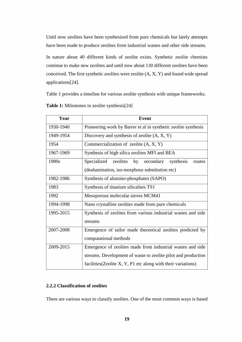
Table 1 provides a timeline for various zeolite synthesis with unique frameworks.
Table 1: Milestones in zeolite synthesis[24]
Year Event
1930-1940 Pioneering work by Barrer et al in synthetic zeolite synthesis
1949-1954 Discovery and synthesis of zeolite (A, X, Y)
1954 Commercialization of zeolite (A, X, Y)
1967-1969 Synthesis of high silica zeolites MFI and BEA
1980s Specialized zeolites by secondary synthesis routes
(dealumination, iso-morphous substitution etc)
1982-1986 Synthesis of alumino-phosphates (SAPO)
1983 Synthesis of titanium silicalites TS1
1992 Mesoporous molecular sieves MCM41
1994-1998 Nano crystalline zeolites made from pure chemicals
1995-2015 Synthesis of zeolites from various industrial wastes and side
streams
2007-2008 Emergence of tailor made theoretical zeolites predicted by
computational methods
2009-2015 Emergence of zeolites made from industrial wastes and side
streams. Development of waste to zeolite pilot and production
facilities(Zeolite X, Y, P1 etc along with their variations)
2.2.2 Classification of zeolites
There are various ways to classify zeolites. One of the most common ways is based

20
on occurrence. Hence we have natural and synthetic zeolites. Some examples of
natural zeolites are Clinoptilolite, Mordenite and Phillipsite.
Another method is based on structure. In such a classification zeolites are grouped
based on specific frameworks and other parameters. They are written as Group 1,
Group 2, Group 3, Group 4, Group 5, Group 6, Group 7[25]. Exact Group and sub-
group can be pinpointed by finding the Si/Al ratio or SiO2/Al2O3 ratio combined
with XRD data.
Another way of classification is based on framework structure types only. Here the
framework is central and chemical composition or SiO2/Al2O3 consideration is
secondary. In such a classification all of the zeolites are categorized in families and
then sub divided into specific types. Some of them are FAU (Faujasite), MOD
(Modernite) etc. Naturally FAU type framework are found in X and Y zeolite types.
XRD data are central to such classification.[26]. In practice the classification based
on just families are used more often.
2.2.3 Zeolite Framework
Zeolite framework structures are key to understanding zeolite chemistry. A
framework type in zeolite describes the connection of tetrahedral coordinated atoms
(T-atoms) in the highest possible symmetry. The framework composition, observed
symmetry and actual unit cell dimensions are not considered. Hence multiple
materials can be put under one designation, e.g., garronite, Na-P1, Na-P2, SAPO-
43 etc are all grouped under GIS framework. A three letter code is assigned (eg
GIS, FAU etc) which is governed by structure commission of IZA (International
Zeolite Association). The codes are derived from name of zeolite, mineral or type
material, e.g., FAU is derived from mineral faujasite, MFI as Zeolite Socony Mobil
etc. Until now about 176 zeolite framework types have been confirmed by the
IZA[27].
The feature that is common to zeolite or zeolite like material is that they all have a
3-D, 4-Connected framework structure constructed from corner sharing TO4 (T is
the metal such as Al, Ti, Fe etc) tetrahedra. The framework structures are open,
consisting of channels and cavities.

21
It is believed that zeolite is formed by two kinds of structural building units which
are primary and secondary structural units. The Primary Building Unit (PBU)
consists of SiO4 and AlO4 which are arranged in such a manner that four corners of
tetrahedron are occupied by oxygen atoms surrounding a central ion (Si4+ or Al3+).
The PBU join together in intricate patterns to form secondary building units (SBU).
The so formed SBUs connect to form different zeolite frameworks[28]. In another
perspective it can be seen that SBUs combine to form unique pores and channels.
These pores and channels are also called oxygen windows. The numerous
combination of similar SBUs gives rise to 176 different framework zeolites. Figure
1[29] illustrates the above idea.
Figure 1: PBU, SBU and their combination to form framework structures[29]
A detailed theoretical description of zeolite always begins with framework type,
size of pore opening and dimensionality of pore channel system. Pore openings are
described by the size of ring that opens the pore i.e n-ring where n is the number of
T atoms (usually also the number of O atoms). An 8-ring is considered as small

22
pore opening, 10-ring a medium one, 12-ring a large one with the effective pore
widths calculated by using effective oxygen radius of 1.35Å. This is just a rough
estimate as the rings can be distorted. A number of structural features such as cages,
channels, chains and sheets are found in various zeolite framework types. A
Truncated octahedron in sodalite cage of zeolite is expressed as a surface with 4-
rings and eight 6-rings. This would be designed as [4686] cage. Figures 2 and 3
below illustrates some cages, subunits and chains[30].
Figure 2: Zeolite cages and subunits[30]
23
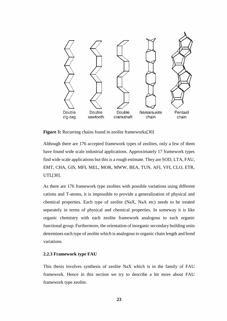
Figure 3: Recurring chains found in zeolite frameworks[30]
Although there are 176 accepted framework types of zeolites, only a few of them
have found wide scale industrial applications. Approximately 17 framework types
find wide scale applications but this is a rough estimate. They are SOD, LTA, FAU,
EMT, CHA, GIS, MFI, MEL, MOR, MWW, BEA, TUN, AFI, VFI, CLO, ETR,
UTL[30].
As there are 176 framework type zeolites with possible variations using different
cations and T-atoms, it is impossible to provide a generalization of physical and
chemical properties. Each type of zeolite (NaX, NaA etc) needs to be treated
separately in terms of physical and chemical properties. In someway it is like
organic chemistry with each zeolite framework analogous to each organic
functional group. Furthermore, the orientation of inorganic secondary building units
determines each type of zeolite which is analogous to organic chain length and bond
variations.
2.2.3 Framework type FAU
This thesis involves synthesis of zeolite NaX which is in the family of FAU
framework. Hence in this section we try to describe a bit more about FAU
framework type zeolite.
24
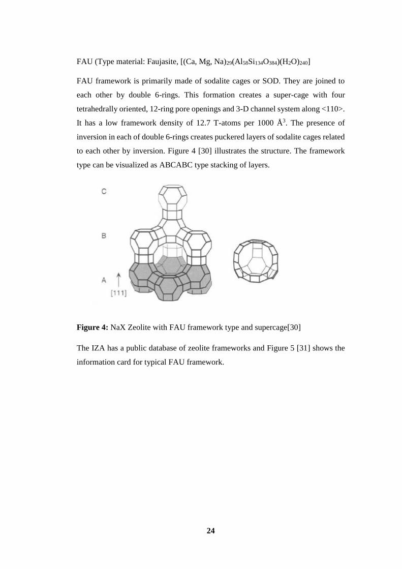
FAU (Type material: Faujasite, [(Ca, Mg, Na)29(Al58Si134O384)(H2O)240]
FAU framework is primarily made of sodalite cages or SOD. They are joined to
each other by double 6-rings. This formation creates a super-cage with four
tetrahedrally oriented, 12-ring pore openings and 3-D channel system along <110>.
It has a low framework density of 12.7 T-atoms per 1000 Å3. The presence of
inversion in each of double 6-rings creates puckered layers of sodalite cages related
to each other by inversion. Figure 4 [30] illustrates the structure. The framework
type can be visualized as ABCABC type stacking of layers.
Figure 4: NaX Zeolite with FAU framework type and supercage[30]
The IZA has a public database of zeolite frameworks and Figure 5 [31] shows the
information card for typical FAU framework.

25
Figure 5: Information card for NaX Zeolite with FAU framework[31]
26
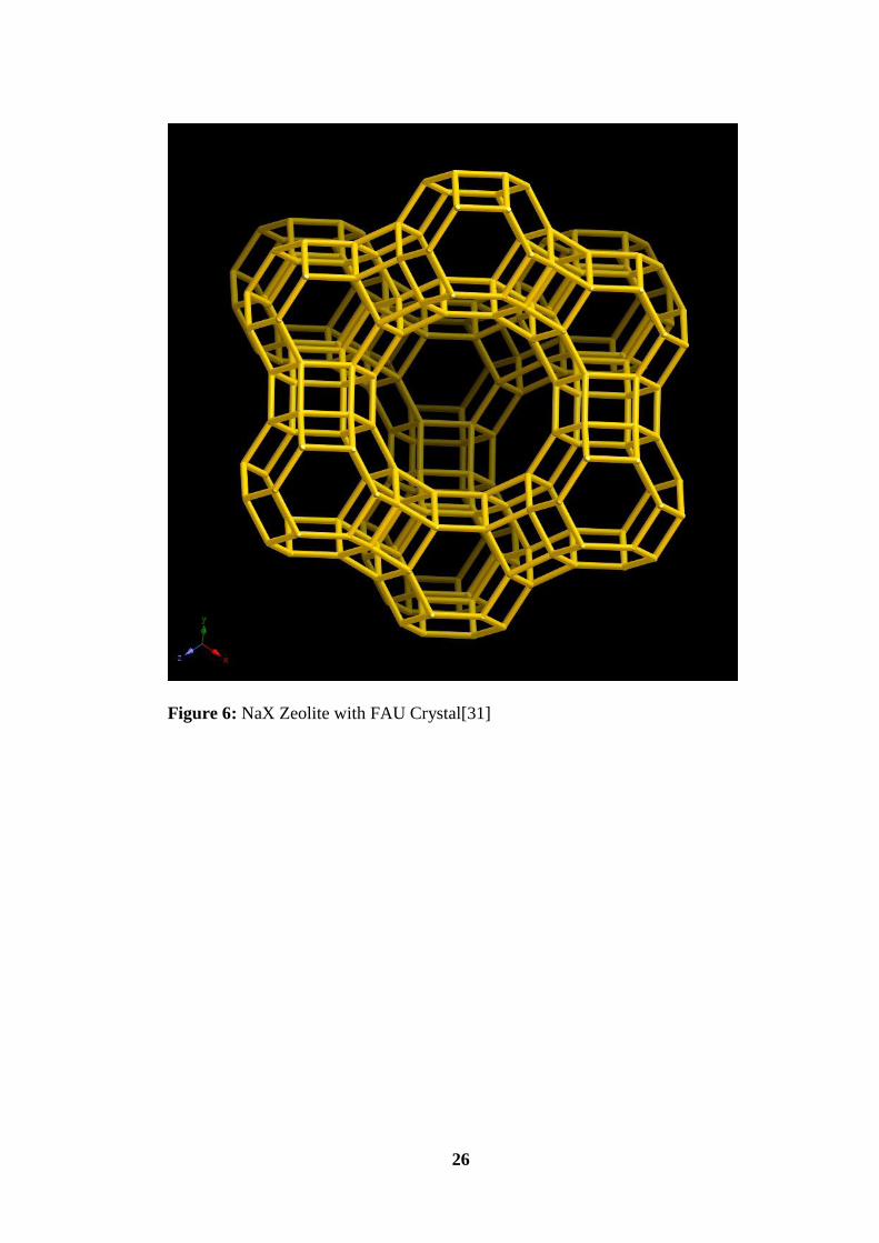
Figure 6: NaX Zeolite with FAU Crystal[31]

27
Figure 7: FAU framework matrix[31]
The combination of large void volume (50%), 12-ring pore opening, 3-D channel
system makes the thermally stable FAU framework type ideal for many industrial
applications.
2.2.4 Zeolite precursors
Various kinds of raw materials with varied percentages can be used for zeolite
synthesis. The raw material sources can be grouped into silica source, alumina
source, silica-alumina source, alkali source. Silica sources are sodium water glass,
colloidal silica, fumed silica, tetramethylaluminosilicate, tetraethylorthosilicate.
Aluminium sources are sodium aluminate, pseudo-boehmite, aluminium hydroxide,
aluminium-isopropoxide, aluminium nitrate, aluminium sulphate, aluminium
metal. The alkali sources could be sodium based alkali, potassium based alkali or
both. The use of alkali carbonate or hydroxide also forms a factor. Certain kinds of
zeolites could be synthesised using specific sodium, aluminium, alkali, alkali-anion
source and solvent. Hence it is quite complicated and hard to generalize. But for
specific zeolites we have specific proven precursors which give desired results[25].
As the framework structures have greatly increased to include phosphorous, gallium
28
etc hence there is a whole other range of such precursors which can be used. In our
case we are dealing with silica-aluminium zeolites hence our discussions will be
limited to relevant precursors only.
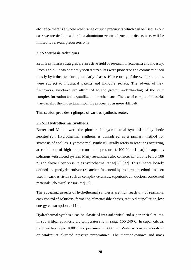
2.2.5 Synthesis techniques
Zeolite synthesis strategies are an active field of research in academia and industry.
From Table 1 it can be clearly seen that zeolites were pioneered and commercialized
mostly by industries during the early phases. Hence many of the synthesis routes
were subject to industrial patents and in-house secrets. The advent of new
framework structures are attributed to the greater understanding of the very
complex formation and crystallization mechanisms. The use of complex industrial
waste makes the understanding of the process even more difficult.
This section provides a glimpse of various synthesis routes.
2.2.5.1 Hydrothermal Synthesis
Barrer and Milton were the pioneers in hydrothermal synthesis of synthetic
zeolites[25]. Hydrothermal synthesis is considered as a primary method for
synthesis of zeolites. Hydrothermal synthesis usually refers to reactions occurring
at conditions of high temperature and pressure (>100 ℃, >1 bar) in aqueous
solutions with closed system. Many researchers also consider conditions below 100
℃ and above 1 bar pressure as hydrothermal range[30] [32]. This is hence loosely
defined and partly depends on researcher. In general hydrothermal method has been
used in various fields such as complex ceramics, superionic conductors, condensed
materials, chemical sensors etc[33].
The appealing aspects of hydrothermal synthesis are high reactivity of reactants,
easy control of solutions, formation of metastable phases, reduced air pollution, low
energy consumption etc[19].
Hydrothermal synthesis can be classified into subcritical and super critical routes.
In sub critical synthesis the temperature is in range 100-240℃. In super critical
route we have upto 1000℃ and pressures of 3000 bar. Water acts as a mineralizer
or catalyst at elevated pressure-temperatures. The thermodynamics and mass
29
transfer properties of high temperature water are very different than ambient water.
The solubility of non-polar species increases and that of ionic and polar compounds
decreases. Moreover under hydrothermal conditions the physical and chemical
properties of reactants change considerably. High temperature and pressure
hydrothermal conditions accelerate rate of reaction in complex ions, intensify
hydrolization reaction and change the redox potential of reactants. Low temperature
hydrothermal synthesis with saturated vapour pressure is much simpler. If reactions
are carried out below boiling point of water then the phenomena involved are not
very complex. The viscosity of water decreases with an increase in temperature
Hence the mobility of ions in water is also enhanced. The pressure and temperature
diagram of water is essential especially for reactions above the boiling point of
water. In case of hydrothermal conditions below boiling point of water the pressure-
temperature diagram may not be very significant. But if the pressure needed is not
significant and there is a large reaction vessel then the saturation pressure is less
and hence safe. In general the degree of filling is 50-80% by volume for
hydrothermal synthesis. In case of low temperature synthesis of <100 ℃ the
saturation vapour pressure generated in not very significant[30]. In our case we will
be dealing with low temperature hydrothermal synthesis.
There are various factors affecting the synthesis of zeolites[32]. Most zeolites are
formed in metastable phases. Zeolite crystallization represents one of the most
complex chemical problems in crystal nucleation and growth[30]. It involves
complex reactions such as solution precipitation, polymerization-depolymerisation
and nucleation-crystallization[30]. The use of complex industrial waste as raw
materials which contain more interfering chemicals than pure chemicals makes the
explanation even more difficult. The large number of variables which affect
formation of specific zeolite phases are batch composition, reactant sources, Si/Al
ratio, alkalinity, water content/dilution, inorganic cations, organic templates, and
solvents, structure directing agents/seeding, temperature, aging and stirring[34].
Hence the use of industrial waste such as CFA often results in formation of mixed
phases of variety of zeolites[34]. It has been recognized that of the above parameters
the most crucial parameter which govern synthesis are batch composition, aging,
alkalinity, water content, temperature and reactivity of precursors[35]. Based on

30
chemical mix and other parameters mentioned above, there are various phase
diagrams. These phase diagrams provide a good approach to design specific pure
zeolite systems theoretically. An example of such a phase diagram is provided in
figure 8 [30]. The system is Na2O-Al2O3-SiO2-H2O at 100℃ with water content of
90-98 mol%, colloidal silica is being used. Another system is Na2O-Al2O3-SiO2-
H2O at 100℃ with water content of 90-98 mol%, sodium silicate is being used
(Figure 9 [30]).
Figure 8: Phase diagram[30]
Figure 9: Phase diagram[30]

31
It is interesting to observe that the use of different precursor gives rise to different
phase diagrams even though all other parameters are same. This is due to level of
reactivity and solubility of the different pre-cursors.
2.2.5.2 Solvothermal Synthesis
Solvothermal synthesis is similar to hydrothermal synthesis but instead of water as
the solvent, a wide variety of organic solvents are used in case to case basis.
Naturally the corresponding reaction parameters and reactivity of species and other
crucial elements are modified. In general, slow reaction rates are found with
variation in viscosity[25]. High viscosity solvents reduce mass transfer by
convention and hence favour large crystals. This fact can be used vice-versa based
on desirability. BASF was the first company to patent non-aqueous solvothermal
synthesis of zeolites in 1982. They manufactured ZSM-5 in ether-water media. In
a specific case CAN type zeolite was synthesised in butane 1,3-diol solvent[36].
The resultant zeolite was free from any barrier, defects compared to one synthesised
in water. It has to be noted that each solvent system will have variety of evaporation
temperature hence pressure-temperature diagrams for specific solvent system being
used needs to be addressed for safety and other reasons. Until now a variety of
alcohols have been used as solvent[37]. The solvent provides the medium for
reaction. It also dissolves or partially dissolves the reactants to form solvent-
reactant complexes which affects the chemical reaction rates. The polarity of the
solvent is the primary factor determining solvating property. The solvent polarity
empirical parameter ETN indicates precursor nutrients as function of crystallization.
ETN is different for solvents with different polarity[36].
2.2.5.3 Fusion and hydrothermal route
This method involves using highly unreactive and crystalline precursors such as
waste materials. This is a very useful method and involves making a batch
composition and then heating it in open vessel in ambient air at 400-600℃ for 1-2
hours. This results in melting of crystalline chemical mix into an amorphous mix
and gradual conversion into aluminosilicates. This product is fused and very hard.
This needs to be powdered and mixed with requisite amounts of solvent and used
in hydrothermal treatment for zeolite production. Fusion temperature, time are
32
crucial factors determining final product. One of the key raw materials for this kind
of approach is CFA, coal bottom ash, waste ceramics etc. Fusion helps to get rid of
volatile unwanted materials present in reaction mix[35] [38] .
2.2.5.4 Microwave assisted synthesis
Microwave is an electromagnetic radiation in the range of 0.3-300 GHz. It has been
recently used in various applications such as chemical reactions, organic-inorganic
synthesis, selective sorption etc. In case of zeolites it has also been put to test. There
have been many reports of the use of microwave assisted methods for zeolite
synthesis. Many variation exists for the microwave assisted synthesis. Some
varieties of zeolites have been made completely using only microwave and some
had a mix of microwave with hydrothermal in various order. The use of microwave
synthesis is also thought to be a great alternate for fusion method/step[39].
Microwave synthesis is fast, cheap and clean. Zeolite synthesis by microwave
method was first patented by Mobil Corp in 1988. Microwave influence include
uniform heating of reaction mixture, increased reaction rate, changing the
association between species in synthetic mixture. The reactions may be enhanced
due to microwave field, absorption of microwave energy by reactants, intermediate
species etc. The distribution of microwave energy can be altered by various factors
such as reactor geometry, temperature, frequency, dielectric permittivity. The
resultant energy distribution can have effects in product quality and quantity[40].
2.2.5.5 Combinatorial synthesis method
Combinatorial chemistry involves making libraries of compounds which are
permutations of a set of physical or chemical parameters[41]. This has attracted a
lot of attention in material science because of immense possibilities. This is widely
being used in drug discovery, new materials discovery for organic, inorganic and
complex compounds. In recent years this approach has also started to find
application in zeolite synthesis[41]. In 1998 the first zeolites were synthesised by
combinatorial method[42]. This generally involves multi autoclave system
arranged so that rapid experimentation takes place to reach the optimum results in
the shortest possible time. Lately Combinatorial method has been exclusively used
in hydrothermal synthesis. In various systems the work is automated with automatic
33
sample mixing, dispensing machines and insitu product washing mechanisms. This
also involves greater accuracy with low sample preparation quantity resulting in
greater savings and higher gains[43]. Even if the sampling is not automated with
machines it does not mean that it is not combinatorial approach. The core idea is
based on carrying out rapid permutations of parameters at a time, e.g., a permutation
set for 10 different chemical compositions are made and put in an oven with certain
temperature[44]. This process can be carried out with a different temperature set or
other variations in parameters. Hence a large family of compounds could be made
in a short time following a logical path.
In 2005 a new strategy involving combinatorial and computational method was
developed for zeolites. The combined approach is a very powerful strategy for new
zeolite discovery. The molecular simulations interaction energies of host-guest
systems, templating ability SDA combined with a possibility to carry out rapid
rational experiments would be the future of new zeolite/materials discovery[45]. It
is believed that extensive mapping of multi component systems could be carried out
using combinatorial approach coupled with rational design of SDAs using
computational method is the way forward.
2.2.5.6 Other methods
Apart from these popular methods there are also other routes under investigation.
Some of them are ionothermal method[46], F- synthesis method[47],
microemulsion based hydrothermal synthesis[48], dry gel conversion method[49]
etc.
2.2.6 CFA Zeolite
Various types of zeolite (NaP1, NaX, NaY, LTA etc) could be derived from
CFA[35] [32]. CFA Zeolites have been researched since 1990s and various reports
from all over the world has verified that it is indeed possible to make and work with
it sustainably. There are reports from USA[32], India[35], China[32], South
Africa[50], Spain[32], Brazil[51], Japan[52], South Korea[53], Australia[54], UK
etc. However it remains an unexplored area in Finland and Northern Europe.
34
CFA precursors contain other components such as Ca, Fe, Ga etc. and hence they
get trapped or encapsulated in the zeolite matrix. CFA Zeolites are often formed in
mixed phases[32]. The formation of pure phase zeolites are quite complicated and
generally not achieved by low cost hydrothermal methods. Hence the zeolite could
be a mix of NaX-A or even more exotic depending on the composition following
the phase diagram[32]. It is worth to note that when using a specific CFA a
combinatorial approach could yield a useful phase diagram. This phase diagram
could be used to predict families of new zeolites from the same CFA. The use of
fusion provides a good chance to obtain pure zeolites[35]. But fusion is often
expensive to maintain and technically hard to handle because of high temperature,
special vessels, stiff products etc. The presence of interfering elements in the gel
mix such as C, Ga, Co, Ti, Ca, Fe etc causes unknown effects. This is one part
which has not been actively researched yet. Its effect in synthesis mechanism is
unknown. But if the primary mechanism is made good enough (assuming presence
of only reacting species such as silica and alumina) then the interferences can be
balanced away. Naturally the smaller the quantity of these elements, the better the
chances to get a high quality product. It can also be thought that unwanted elements
are trapped in the zeolite cages and channels. Moreover these interfering elements
are quite minute so there is no concern of leaching. CFA Zeolites are often brown
or light brown in colour. This is due to presence of transition elements which impart
such colour. The presence of unburnt carbon also gives it a dark look which
gradually fades with multiple washing steps[28]. The size range of the zeolite varies
a lot depending on the process followed. It also depends on the quality of original
CFA used. So does the morphology and purity. Depending on the above parameters
we can get CFA Zeolite which could be inferior or even superior to standard
commercial zeolites. The presence of high amorphous phase in CFA is crucial to
have equivalent amount of zeolite as end product. The quartz, mullite and other
crystalline phases remain inert.
In case of waste materials such as CFA which is a very complex chemical mix in
terms of composition, size range, reactivity of each component, crystallinity and
amorphous content, interfering species in the CFA mix makes the design of
experiments very tricky. Due to its heterogeneous mix and range the use of CFA as
35
precursor requires extensive research in a case to case basis for consistent
results[35] [23]. More specific information has been provided in results and
discussions.
CFA Zeolites have been researched since 1990s and various reports from all over
the world have verified that it is indeed possible to make and work with it
sustainably.
The advent of circular economy and large volumes of CFA has prompted experts
to find practical scale-up routes for CFA Zeolites. There are confirmed reports for
CFA Zeolite pilot plants in Spain[55], India[56] etc. Detailed discussion about pilot
plants are out of scope for this literature.
2.3 Zeolite properties and applications
2.3.1 Cation Exchange
Zeolites are highly porous substances with lots of channels inside. The cations such
as sodium, potassium, calcium etc are bonded to the framework. However, they can
be displaced by cations of greater charge.
Cation exchange capacity of CEC is determined by, strength of adsorption[57] such
as:
Al3+ > Ca2+ > Mg2+ > K+ = NH4+ > Na+ > H+
And the relative concentration of cations in solutions.
The most common applications involve radioactive decontamination such as
removal of strontium and cesium from waters originating from nuclear power
stations[57]. Industrial water softners to stop lime-scale blocking in cooling
pipes[25]. Environmental remediation by removal of heavy metals such as lead,
zinc, copper, mercury, cadmium etc[35]. The most commonly used zeolites in this
case are zeolite X, zeolite Y, silicalite etc.
2.3.2 Dessication
Zeolite are excellent drying agents[58]. They remove water/moisture from
atmosphere around them. Moreover zeolite holds water of crystallization, the exact
36
number varies from zeolite group and subcategories hence hard to generalize. But
the reaction below summarizes the process:
Hydrated Zeolite Anhydrous zeolite + water (2)
Moreover, the loss of water by zeolite will result in the zeolite taking back the water
in order to establish equilibrium in the system as per Le Chateliers principle[59].
The most common variety of zeolite used in this case are zeolite X and zeolite Y.
2.3.3 Water softening
Hard water contains Ca2+ and Mg2+ and is a major issue. Water softening is often
obtained by passing hard water over a column packed with zeolites. Moreover it is
also used in detergents as water softners. The zeolites encapsulate the Ca2+ and
Mg2+. Infact zeolite is a prime choice instead of polyphosphates because it prevents
algal bloom effect of pollution by phosphates [58]. Hence latest detergent
formulations use zeolites instead of polyphosphates. The most commonly used
zeolites in this case is Zeolite A. The equation below describes:
2NaA(s) + Ca2+(aq) CaA2 + 2Na+ (aq) (3)
Na+ does not precipitate with soap as Ca2+ does hence the water has been softened.
Since it is an ion-exchange reaction hence the sodium zeolite can be regenerated by
passing concentrated sodium chloride which shift the equilibrium as per Le
Chatelier’s principle[60].
2.3.4 Anion absorption
Toxic anions could be removed by reaction of heavy metal cations previously ion-
exchanged into zeolites[61].
Ag+-zeolite + Na+ + I- → Na+zeolite + AgI (precipitated) (4)
The above equation 4 is an excellent example of silver ion-exchanged zeolites used
for removing radioactive iodine (iodide) in the form of insoluble AgI[62]. The
unique thing about the process is that the insoluble AgI is both formed and caged
inside the zeolite pores. Zeolites are often tailored to cage radioactive substances or
allow it to form separate precipitate. The saturated zeolites can be removed for
disposal. Similar approach can be applied to cyanide, arsenic, chromate, molybdate
etc[63].

37
2.3.5 Molecular sieves
Categories of zeolites with small pores selectively adsorb small polar molecules
such as water and so these zeolites are outstanding drying agents[25]. Moreover
these molecular sieves are also used in separation of large and small molecules in
separation technologies[64].
2.3.6 Hydrocarbon separation
Zeolites are used extensively in petroleum, petrochemical, biorefining and fine
chemical sectors for hydrocarbon separation[25]. An example to that can be
separation of linear n-alkanes (needed in various utilities including detergent
manufacture) from branched alkanes[65]. It is obtained by passing them through a
column of packed zeolite 5A. The n-alkanes pass more slowly into the zeolite
channels as they are absorbed more selectively than the branched alkanes. Hence
the property of selectivity is of prime importance here. Millions of tonnes of n-
alkane is produced annually by this method[64].
2.3.7 Medical applications
Zeolites are applied to wounds in accidents and surgeries. They cause rapid
inhibition of bleeding[66]. Zeolites are commonly used in kidney dialysis[67]
instruments to absorb ammonia from blood and preventing it from building up in
the body. Some commercial products are Hemosorb and QuikClot[68].
2.3.8 Agriculture
Agriculture finds great use of zeolites[67]. Zeolites are used to reduce loss of
nitrogenous nutrients in three ways. Urea is caged within the zeolite matrix which
prevents it from leaching into root zones. Urea trapped inside zeolite matrix slows
down the conversion of urea into ammonium ions by soil bacteria. Adsorption of
ammonium ions into zeolite matrix protects them from nitrifying bacteria which
could convert them to leachable nitrate ions. The ammonium ions could be released
slowly into the soil over time.

38
Ammonium zeolites are often mixed with phosphate minerals to slow release
ammonium phosphate fertilizers. As more of the fertilizer is absorbed by plants
more of the phosphate is released from the zeolite adhering, according to Le
Chatelier’s principle[67].
2.3.9 Desulphurization operations
Zeolites are used widely in various desulphurization operations[65]. One such
example is nickel exchanged zeolites that can absorb sulphur compounds from
diesel in an aim to reduce emissions from transportation[24]. As this is directly
related to acid rain, it is a hot topic.
2.3.10 NOX Removal
Vehicle and industries have high NOX emissions. One of the key substances used
to decrease NOX is using zeolites[65]. An example is use of catalytic convertors in
vehicles where a very high quality, high endurance catalytic zeolite is used. In many
cars the most costly item is the catalytic convertor containing the high grade
zeolite[69]. EU and North American legislations demands the use of very powerful
catalytic convertors in vehicles to be permitted in streets.
2.3.11 Construction industry
Zeolite is a light weight building material as it can be easily cut with hand saw and
very durable in dry climates. It is also fabricated into light weight cements. China
consumes 2.5 million tonnes of construction zeolites per year[70].
2.3.12 Heating systems
When water is adsorbed in zeolite it releases heat[58]. This principle can be used in
a heat pump system which uses the available energy for real heating rather than let
it be wasted[25].

39
2.3.13. Separation of gases
This application is one of the largest users of zeolites[65]. One critical application
involve separation of oxygen from air[71]. The oxygen purity attained is 95% and
is often used for patients with breathing and lung disorders. Nitrogen is selectively
absorbed into the zeolite instead of oxygen because of higher electric quadrupole
moment. This leads to separation of nitrogen (80%) of air and hence giving only
pure oxygen[24].
Other examples where NaX zeolite is exclusively used include industrial drying of
gas[65]. Solvent vapour recovery[72], air pollution control[73] and removal of trace
ammonia[74]. Industrial production of oxygen and nitrogen from air[75]. Hydrogen
production from steam-methane reforming gas and refinery off-gas[76]. CO2-CH4
separation from landfill gases, alcohol dehydration and gas chromatography[24].
2.3.14 Liquid separation and purification
In bulk liquid separation zeolites are widely used. Separation of
paraffins/isoparaffins, aromatics[58]. Separation of p-xylene[77], o-xylene and m-
xylene[77]. Separation of glucose/fructose[78]. Separation of p-diethyl
benzene/isomer mixture[79]. Chromatographic analytical separations[75].
2.3.15 Biomass upgrading and derivatives
The key properties of zeolites used in this category of applications are acidity
(presence of acidic sites) and shape selectivity making zeolites a catalyst of choice
for C-C bond rearrangements[80]. The key applications are catalytic cracking and
hydrocracking which allows reduction of molecular weight of heavy biomass
constituents. The key biomass components are vegetable oils (disaccharides),
polymers such as cellulose, hemicellulose, lignin etc[81]. In addition, isomerization
reactions are also catalyzed by zeolites. It involves valorization of n-alkane rich
fractions from triglyceride deoxygenation[82]. Moreover, sugar transformation
reactions yielding simple sugars from more complicated ones are also an important
class of applications[83]. A new set of biomass upgradation reaction also includes
alkylation of aromatics[83]. As such this approach is used in transformation of

40
aromatics and phenols obtained from lignin conversion. Various families of zeolites
including FAU class NaX ones are used in various applications mentioned above
in this section[80]. In the present context we can also say that NaX zeolite is used
in biodiesel production[84]. Acetone a common industrial chemical is produced
from bioethanol, biomass, biomass wastes (sewage sludge, fermentation residue,
livestock manure) using various zeolites including NaX[80]. Lactic Acid, an
important intermediate is often produced by transformation of trioses or other
sugars using FAU catalysts such as NaX[85]. Dehydration of sugars to esters are
conducted using FAU catalysts[86]. FAU class of zeolites are used in aldol
condensation of furfural with acetone (from biomass) to obtain aldehyde-ketone
category of products[87]. The examples provided are just some highlights and in
practice there are much more cases.
2.3.16 Geotechnical Applications
Zeolites are often used in grouting[88], asphalt filler[89], sub-grade
stabilization[90], pavement base course[91], general engineering fill[22], structural
fill[22], soil amendment and infill[90]. In case of soils and fills zeolite adsorbs and
absorb water which leads to control of water in release and absorption. This is a key
aspect because it prevents swelling of soil. If soil or filler swells too much then they
could expand when wet and shrink when dry. This creates pressure which can crack
pavements, basement floors, driveways, pipelines and foundations. Zeolite addition
in geomaterials brings positive benefits without upsetting the basic chemical
composition as most components are silica and alumina in various forms[92].
2.4 Circular economy
2.4.1 Introduction
Circular economy is the next generation concept for transformation of traditional
patterns of economic growth. Until now the industrial production has followed a
linear path but as natural resources become scarcer and legislation stronger a new
concept has been developed. This concept of circular economy is considered a

41
possible solution. This is still a general term and a precise definition has not been
framed yet as this combined concept is new.
The origins of circular economy can be traced back in 1983 when Gro Harlem
Brundtland[93] former director general of WHO (World Health Organization) lead
an initiative to explore a global agenda for change with the sole purpose of creating
a bedrock for development of long term sustainable strategies and its implication
by 2000 and beyond[94].
2.4.2 The current situation
The current industrial system at a global scale is a linear one, where the concept of
holistic synergy between industries is lacking which leads to high yield of wastes
and outgoing streams. In the current linear style environmental degradation takes
place by depletion of natural resources by mining and indiscriminate exploitation.
This leads to a decrease in value of natural resources available due to
overexploitation and pollution originating from waste [95].
From an ecosystem point of view an industrial symbiosis is where one industry uses
the other’s waste as raw material. From the service sector perspective efforts are
being made to make high quality materials which ensures a longer life cycle of the
product and hence lesser production, lesser wastes and delaying waste generation.
This is a logical extension of Rs i.e Reduce, Reuse, Recycle policy of Sustainable
development framework programs[96].
2.4.3 Basic concepts and perspectives
One of the ideas of the circular economy concept is that there is ultimately no net
effect on nature and it infact restores damages done during natural resource
acquisition. One key aspect is that during the entire product life cycle there is no
net generation of waste. Circular economy concept compels us to investigate an
“approach to redesign approach”. This is a radical approach which will be critical
to next generation industry and policy making and it is a pity that these have not
arrived in school text books yet. The uniqueness in this approach lies in the fact that

42
we focus on redesigning systems for manufacturing, service supply ecosystem and
not merely the individual components or resource utilization[97].
Another inherent meaning which can be formulated in the very term “circular
economy” is the idea of cycle relating to biogeochemical cycles and recycling.
Hence from those we know a cycle can adapt to change but the key aspect is the
rate of change and its management.
2.4.4 Key trends and new perspectives
The key trend for circular economy is that the initiatives arose because of
legislations rather than push by the academic and scientific community. Resource
crunch and environmental disasters were the key drivers in the evolution of this
concept and they still are. From a business and legislative perspective circular
economy can be seen as natural balance between economic development and
resource, environmental protection.
Most of the sustainable framework plans have a triad approach with benefits in
economic, social and environmental regimes. The drawback on framework plans in
case of circular economy is that no foreseen benefit could be predicted in the social
front. It is understood that efficient resource utilizations bring immense benefits to
not only our generation but secures the next generation but an explicit recognition
of the social aspect is still missing and needs to be rethought[98]. It still needs to be
thought how circular economy framework can lead to greater equality in society but
perhaps between all beings on earth. Hence it will be a debatable issue when
framing policies and redesigning the new approach[99].
Circular economy for companies makes great business sense to keep rare materials
in their loop and use less raw materials especially when their prices are volatile and
forecasted to rise. It further enhances the independence of companies and whole
nations. This kind of approach could create new jobs and preserve old ones.
Moreover instead of creating new mining jobs there will be a lot of recycle related
vacancies [100]. Hence jobs from mining would be diverted to new eco-friendly
and sustainable sectors. The trend with various waste service companies are shifting
from a centralized processing facility to scattered modular system of processing

43
units. These are often known as modular service systems with onsite processing and
purification with real time monitoring[101].
2.4.5 Policy making initiatives for circular economy in various countries
The European Commission adopted a policy of “Towards circular economy: a zero
waste programme for Europe” in December 2014. Initially this was greeted with
great resistance by industrial lobbies. But later it was thought to be inevitable for
the security and self-sufficiency of Europe. It is widely believed that this will be a
great step to make Europe self-sufficient in natural or rare earth resources[102]. It
would play a direct role in reducing conflict in commercial markets and to stop wars
over natural resources. One EU report concluded that aluminium cans can have
infinite recycling possibility and hence this can be used to greatly replace constant
demand for some other product that utilizes aluminium. Increasing recovery rates
and putting a levy fee/refund policy on each can go a long way to encourage
recycling and engaging in less mining[95]. Redesigning what we consume, how we
consume, incentives will go a long way to stage a conductive platform for constant
development of circular economy. The EU believes that 2 million new jobs will be
created in Europe itself and 600 million euros will be saved annually with self-
sufficiency among other benefits[103].
In the UK a prominent think tank Ellen Macarthur Foundation commissioned a
number of reports in 2012-2014. The topics of these were drawbacks of linear
economy, resource loss, service ecosystem erosion and the eventual threat to global
prosperity. In another report new business models were developed to address
benefits of circular economy in cost of production, life span aspects of products,
waste as raw material and essence of circles which culminates into source material
remaining uncontaminated leading to greater distribution and material productivity
and lesser costs. In November 2014 the UK government encouraged the principle
and went forward to endorse it. We can be quite optimistic about new laws coming
in favour of circular economy soon[104].
In France the concept has been greeted with enthusiasm and as recently as in June
2014 during the “Green Week” The French Executive Commissioner for

44
sustainable development confirmed France´s commitment to convert the nation into
a leading player into circular economy sector. Various French firms such as SNCF,
La Poste, Capenergies etc have partnered with various institutions to develop
business models in this field[105]
In Finland, clean technologies sector is a growing and is thought be the game
changer to bring greater economic prosperity. Motivated by EU Environmental
mandates the government of Finland has also passed policies encouraging circular
economy from 2014 onwards. For instance using landfills for various types of ashes
will be prohibited completely from 2016 onwards. Lot of investments are being
made by companies to upgrade their production to suite to a circular economy
ecosystem. The waste management companies are in the forefront of these
pioneering initiatives as this means greater business and adherence to legislations.
In Finland more of the policy support came from SITRA through its social
experiments and other initiatives which showed that circular economy is worth 2.5
billion euros in Finland alone[106]. Hence a lot of funding is being provided by
TEKES, government and various institutions to make innovative firms which can
exploit this growth opportunity in Finland and globally[107].
The first of the initiatives for circular economy in China took place in 1990s and
concrete visible policy adjustment in the 5-year plans started taking place since
2005. The drive behind circular economy has been to stop conflicts between
economic growth, resource shortage and pollution. In China it has been
implemented in three levels i.e., cleaner production in companies, environment
friendly special economic zones, overall provinces, cities and towns[108].
It is clear that in the future there would be whole departments or ministries looking
into circular economy. In terms of legislations one major drawback is issue of
permit allocation. The side steams and by-products of industries termed as special
category waste materials/ hazardous waste can be handled by limited entities which
greatly prohibits innovation. One unique example is exclusive rights to handle
hazardous waste and its incineration.

45
2.4.6 Circular economy aspect in CFA Zeolite production and application
Figure 10: Circular economy concept for zeolites
A circular economy model has been created for waste to zeolite production and
application. Figure 8 illustrates a mechanism which is truly eco-friendly, holistic
and sustainable. The industry and society produces the raw materials termed as
waste/by-products/side streams. In our context these waste materials are silica,
alumina, alkali rich substances in the form of ash, sludge and slags. It is worth
noting that the industries under consideration are truly huge and quantity of waste
produced is immense. The sectors from which these wastes are derived forms the
very foundation of modern industry and society. Power plants, silicon, aluminium,
steel, caustic soda etc to name a few. The appropriate disposal is a great issue among
other problems associated with these wastes. As the quantities involved are quite
large there is economic value attached to it. Hence collection of these wastes leads
to a certain fee (€). The waste materials are converted to zeolite in the zeolite
factory. The zeolite factory utilizes the unique process developed by us. The factory
produces zeolite and extractable heat. The zeolite could be sold for revenue. The
heat energy could be sold to society and industry. The heat energy can also be
circulated back to the zeolite factory for internal needs leading to lesser operating
costs. Zeolites are very versatile materials with large scale applications. Some of

46
the applications have been shown in Figure 10 and section 2.3. Considering the
example of waste water treatment for heavy metal removal, we can use zeolite for
removing heavy metal, which generates revenue followed by selling of those heavy
metals generating additional revenue. The used zeolite is regenerated multiple times
and finally used in low value applications such as geotechnical projects (road
construction, fillers etc) at the end of its life cycle. It could also be melted and
powdered to extract remaining valuable metals at the end of its life cycle. The
powder is mostly amorphous silica, alumina or clay and can be easily reused for
zeolite precursor or other purposes. Both the heavy metal and treated water is
circulated back to society and industry.
In case of water laden with ammonia or phosphorous the zeolite would be used to
remove organics. The ammonia/phosphorous laden zeolite would be used as
fertilizer. As zeolite is silica, alumina or clay material, it integrates with the soil
without any hindrance. The water is circulated in society and industry. Hence
multiple revenue streams are generated from water purification service, fertilizer
revenue and treated water reuse revenue/savings.
From both the examples above we can understand that the model illustrated is truly
circular, holistic and sustainable. It does not involve use of net virgin natural
resources. This approach benefits the social, economic and environmental regimes.
Hence we can conclude that our current approach of circular economy is truly eco-
friendly, sustainable and economically advantageous for industries to embrace it
quickly.
47
3 EXPERIMENTAL
3.1 Coal Flyash
The CFA under consideration has been sourced from a major Finnish energy
generation company. Various analytical methods were used to analyse the CFA.
Analysis techniques such as EDX, SEM, XRD, BET were used. These variety of
techniques were employed to determine if the CFA was the appropriate sample/raw
material eg: pulverized bed ash has a completely different morphology than
fluidized bed. Hence with conjunction of various analysis techniques the decision
about suitability of raw material could be achieved.
3.1.1 Pre-treatment
The raw CFA was sieved using Sieve shaker SV005 (Contact Impact Test
Equipment Ltd, Milton Keynes, England) to get rid of excess unburnt carbon. The
sieve gratings (in microns) used were 600, 400, 200, 150, collector at the bottom.
The process of sieving was conducted for 30 minutes non-stop. The sieved CFA
was termed as “refined CFA”.
The refined CFA was weighed before and after (being heated at 130℃) to find
amount of adsorbed moisture.
The refined CFA was thermal treated at 1050℃ for 2h hours to find out LOI (loss
of ignition).
The raw CFA and refined CFA was subjected to temperature of 1050℃ for 2 hours
each to find the effect of sieving on unburnt carbon removal.
The machine used for heating and drying was HTC 03/14-HTC 08/16 (Nabertherm,
New Castle, Germany). The machine had a temperature accuracy of ±3.

48
3.2 Zeolite
3.2.1 Synthesis process
The process starts with mixing of requisite amounts of CFA with NaOH and water.
The solution was then aged for 24 hours (fixed time). The solution was continuously
stirred at 650 rpm for the whole duration of ageing. Ageing and stirring were
conducted at ambient room temperature of 21℃. The solution chamber was made
airtight to avoid loss of water and hence keep the chemical composition constant.
The stirred and aged solution was transferred to teflon autoclaves. The teflon
autoclaves were put in a preheated oven at various temperatures between 60-85℃
for crystallization. The temperatures used were 60℃, 65℃, 70℃, 75℃, 80℃, 85℃.
It was a single step hydrothermal process. The zeolite was retrieved and washed
with distilled water. The washed zeolite was put in an oven for drying. The drying
temperature was 105℃ and time was 16 hours. The zeolite was retrieved and
grinded using mortar and pestle to make it a fine powder. The powdered zeolite was
stored in a sealed container. The synthesis process was optimized to produce
unburnt coal and waste heat. The unburnt coal was retrieved during sieving and
waste heat was produced during batch composition preparation.
The primary challenge was quantification of amorphous SiO2 and Al2O3 from CFA.
The part of SiO2 and Al2O3 from CFA should be amorphous for reaction. The
amorphous and crystalline content of silica and alumina could not be distinguished
quantitatively due to the mixed phase and complex nature of CFA hence a technique
was devised to overcome that technical challenge.
A specific SiO2/Al2O3 ratio was assumed each time. This ratio was considered the
reactive amorphous part. This would be typically lower than EDX values because
of the presence of inert quartz and mullite. Hence the overall amorphous SiO2 is
lower because it is distributed in quartz and mullite components. Hence the real
reactive SiO2 would always be much lower. The corrected Al2O3 (only present in
mullite) would also be less compared to original EDX values, but the amount of
total decrease would be less compared to SiO2. The optimum SiO2/Al2O3 mixed
with calculated parts of other chemicals will only give NaX if the reactivity among
49
amorphous phases is not too stark. With the specific SiO2/Al2O3 ratio a fixed
calculated ratio of NaOH and water (based on stoichiometry) was reacted to get
NaX zeolite. The idea is based on the fact that only the correct amorphous and
reactive SiO2/Al2O3 ratio will react with complete NaOH stoichiometrically to give
a pure form NaX zeolite. If the incorrect SiO2/Al2O3 ratio is used with NaOH and
water then there will be different products/ multiple products/ mixed zeolite phases
due to unused or over used active phase. Specific molar ratios of SiO2, Al2O3,
NaOH and water (with homogeneous reactivity) at specific temperature range gives
specific zeolites only. Explicitly SiO2/Al2O3 ratio was considered because it is the
core TO4 building structure.
This is a very new approach to find a real solution to amorphous quantification of
CFA in a very short time. Such an approach has been engineered and implemented
for the first time in the world in case of CFA Zeolites.
To implement the above idea, rational planning of experiments were conducted
with combinatorial approach. CFA Zeolite Phase diagrams from literature were
used but due to the variation of different CFA all over the world it did not prove
very helpful. Among all the chemical synthesis methods available, hydrothermal
treatment was chosen for its simplicity in implementing and scale up. The oven
used for hydrothermal synthesis was “VT 6025, Heraeus” manufactured by Thermo
Scientific.
3.3 Chemical composition and EDX analysis
EDX analysis of CFA and zeolites were carried out in Åbo Akademi University
Process Chemistry Centre in Turku. The instrument used was Thermo Scientific
UltraDry SDD EDS-system (Thermo Scientific, Waltham, USA). The EDX
analysis was used to determine chemical/elemental composition of CFA.
The CFA used for experiments related to zeolite synthesis were all refined CFA.

50
3.1.3 SEM Analysis
The refined CFA and zeolites were subjected to SEM analysis carried out at Åbo
Akademi University Process Chemistry Centre, Turku. The instrument used was
Leo 1530 Gemini (Zeiss, Jena, Germany). The samples were carbon coated. Sample
preparation and instrument handling was conducted by a third party expert.
3.1.4 XRD Analysis
The refined CFA and zeolites were subjected to XRD analysis carried out at Aalto
University Department of Inorganic Chemistry. The instrument used was PAN
Analytical XpertPRO MPDα1 (PANalytical, EA Almelo, The Netherlands). The
radiation source was Cu-Kα1. Standard sample preparation procedure was
followed[109]. Each sample was scanned for 30 minutes. The data matching
software used was Xpert HighScore. The database used for matching was ICDD
(International Centre for Diffraction Database). The graph has been plotted by
processing XRD raw data in Origin PRO.
3.1.5 BET Analysis
The refined CFA and zeolites were subjected to BET analysis carried out at Aalto
University Department of Forest Products Technology. The instrument used was
TriStar II 3020 (Micromeritics, Norcross, USA). Standard sample preparation
procedure with degassing was followed[110]. The adsorption-desorption
experiments were carried out at 77K.
3.2.6 Statistical Analysis
Various BET data for zeolites at 75℃ were collected and statistical analysis carried
out. Some of the parameters and formulas used are provided below[111] [112]:
x̅ =∑X
N (5)
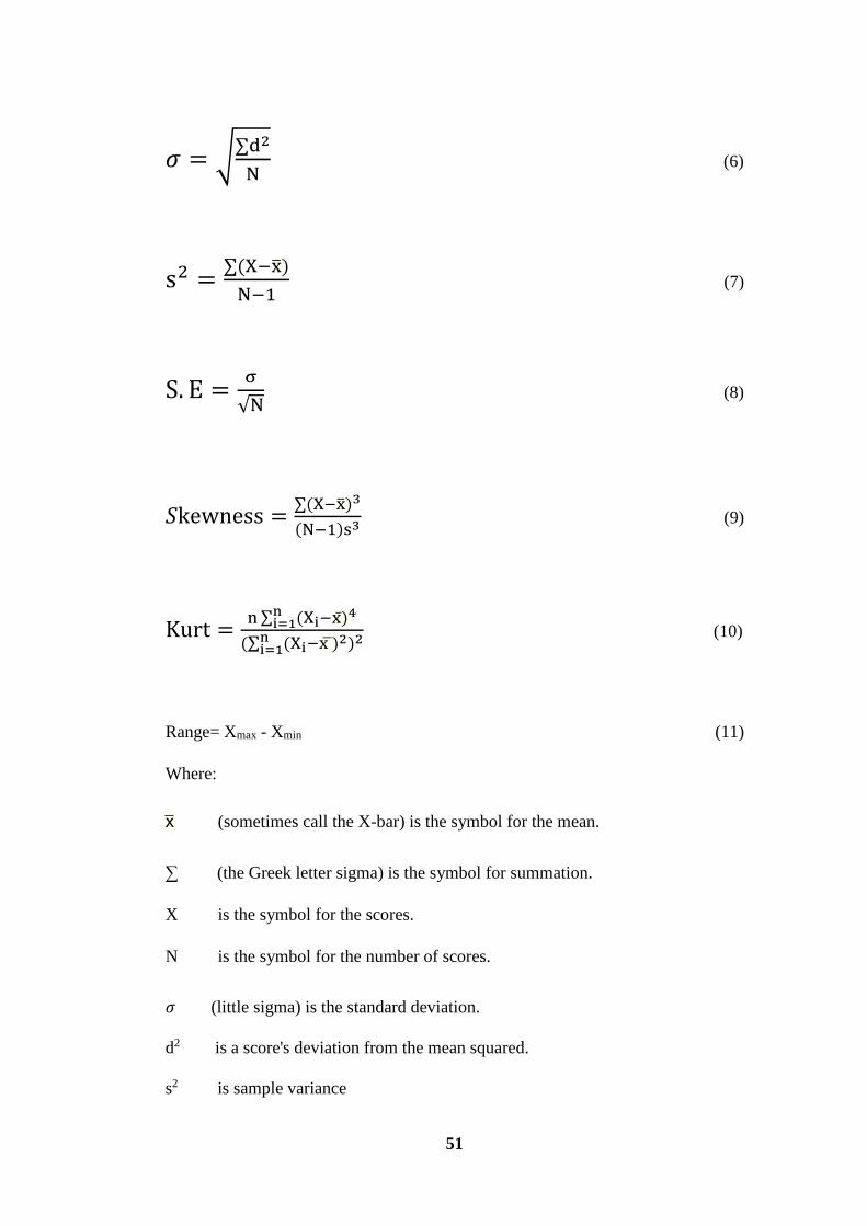
51
𝜎 = √∑d2
N (6)
s2 =∑(X−x̅)
N−1 (7)
S. E =σ
√N (8)
𝑆kewness =∑(X−x̅)3
(N−1)s3 (9)
Kurt =n ∑ (Xi−x)̅4n
i=1
(∑ (Xini=1 −x ̅)2)2 (10)
Range= Xmax - Xmin (11)
Where:
x̅ (sometimes call the X-bar) is the symbol for the mean.
∑ (the Greek letter sigma) is the symbol for summation.
X is the symbol for the scores.
N is the symbol for the number of scores.
𝜎 (little sigma) is the standard deviation.
d2 is a score's deviation from the mean squared.
s2 is sample variance

52
S.E Standard error
Kurt is Kurtosis
n score number
The results have been calculated in MS Excel 2013 using the Data Analysis tool.

53
4 RESULTS AND DISCUSSION
4.1 Coal Flyash
4.1.1 Pre-treatment
Table 2: Drying data
Serial
Number
Weight
before drying
(g)
Weight
after drying
(g)
Moisture loss
(Wet basis
%)
Moisture loss
(Dry basis
%)
1 10.01 9.99 0.19 0.20
2 20.06 20.04 0.10 0.09
3 30.00 29.97 0.10 0.10
Average - - 0.12±0.05 0.13±0.06
MDn% =(WB−WA)∗100
WA (12)
MW% =(WB−WA)∗100
WB (13)
AD =MD1+ MD2+MD3
3 (14)
AW =MW1+MW2+MW3
3 (15)
Where MDn% is moisture loss percentage (dry basis)
MWn% is moisture loss percentage (wet basis)
WB is weight before drying (g)
WA is weight after drying (g)
n is integer (1,2,3) corresponding to serial number
AD is average of moisture loss percentage (dry basis)

54
AW is average of moisture loss percentage (wet basis)
Table 2 provides moisture content data. We can observe that average of moisture
loss percentage (dry basis) and average of moisture loss percentage (wet basis) are
0.13±0.06 and 0.12±0.05 percentage each. This shows that CFA does not adsorb
high quantity of moisture. This also shows that this specific CFA is hydrophobic.
This is in agreement with literature which have values of approx. 0.2%[113]. The
practical implication would be it could be stored without complicated desiccation
system. It can also be stored in a humid environment without grave implications.
Hence there is less initial investment and maintenance cost.
Table 3: LOI of refined CFA
Serial Number Weight before
combustion (g)
Weight after
combustion (g)
Loss of ignition
%
1 10.02 9.59 4.29
2 20.70 19.78 4.44
3 30.78 29.43 4.38
Average of refined
CFA (AR)
- - 4.37±0.05
Table 4: LOI of raw CFA
Serial Number Weight before
combustion (g)
Weight after
combustion (g)
Loss of ignition
%
1 10.02 9.55 4.69
2 20.46 19.50 4.69
3 31.11 29.76 4.33
Average of raw
CFA (AC)
- - 4.57±0.2
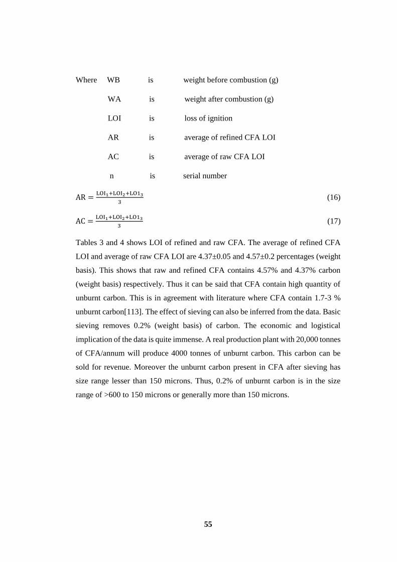
55
Where WB is weight before combustion (g)
WA is weight after combustion (g)
LOI is loss of ignition
AR is average of refined CFA LOI
AC is average of raw CFA LOI
n is serial number
AR =LOI1+LOI2+LO13
3 (16)
AC =LOI1+LOI2+LO13
3 (17)
Tables 3 and 4 shows LOI of refined and raw CFA. The average of refined CFA
LOI and average of raw CFA LOI are 4.37±0.05 and 4.57±0.2 percentages (weight
basis). This shows that raw and refined CFA contains 4.57% and 4.37% carbon
(weight basis) respectively. Thus it can be said that CFA contain high quantity of
unburnt carbon. This is in agreement with literature where CFA contain 1.7-3 %
unburnt carbon[113]. The effect of sieving can also be inferred from the data. Basic
sieving removes 0.2% (weight basis) of carbon. The economic and logistical
implication of the data is quite immense. A real production plant with 20,000 tonnes
of CFA/annum will produce 4000 tonnes of unburnt carbon. This carbon can be
sold for revenue. Moreover the unburnt carbon present in CFA after sieving has
size range lesser than 150 microns. Thus, 0.2% of unburnt carbon is in the size
range of >600 to 150 microns or generally more than 150 microns.
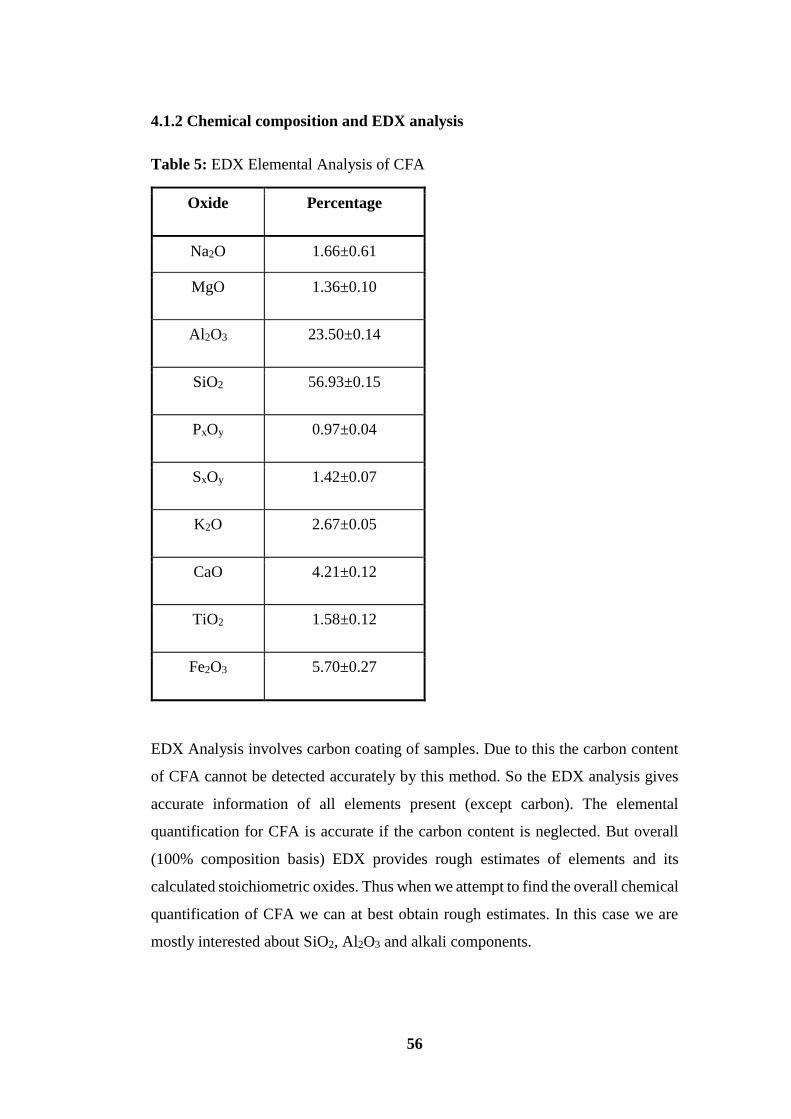
56
4.1.2 Chemical composition and EDX analysis
Table 5: EDX Elemental Analysis of CFA
Oxide Percentage
Na2O 1.66±0.61
MgO 1.36±0.10
Al2O3 23.50±0.14
SiO2 56.93±0.15
PxOy 0.97±0.04
SxOy 1.42±0.07
K2O 2.67±0.05
CaO 4.21±0.12
TiO2 1.58±0.12
Fe2O3 5.70±0.27
EDX Analysis involves carbon coating of samples. Due to this the carbon content
of CFA cannot be detected accurately by this method. So the EDX analysis gives
accurate information of all elements present (except carbon). The elemental
quantification for CFA is accurate if the carbon content is neglected. But overall
(100% composition basis) EDX provides rough estimates of elements and its
calculated stoichiometric oxides. Thus when we attempt to find the overall chemical
quantification of CFA we can at best obtain rough estimates. In this case we are
mostly interested about SiO2, Al2O3 and alkali components.

57
The majority of CFA consists of SiO2 and Al2O3. It also contains high amounts of
iron oxide and calcium oxide. There is very minor quantity of TiO2. One of the
positive aspects of this CFA is that it lacks toxic leachable elements such as Co, Cr,
V, Cd, Ar, Pd etc. Hence there should be less negative interference from those
elements. It also contains some Na and K which should provide some charge
stabilization to zeolite framework. Some drawbacks include high percentage of
unburnt carbon, iron oxide, sulphur and calcium oxide. The effects of these are
explained in later sections of zeolite synthesis. The CFA sample can be classified
as F-class[114], medium grade. A standard called ASTM C618 is used for the
classification. Table 6 below shows the comparison:
Table 6: CFA comparison and standardization[114]
Property CFA (%) ASTM C618 Requirements, (%)
SiO2 + Al2O3 + Fe2O3 85.43 70 (minimum)
SO3 1.42 5 (maximum)
Moisture content 0.13 3 (maximum)
Loss on Ignition 4.57 6 (maximum)
The combined thermal and EDX analyses provide rough estimates of oxide
quantities. It provides no information about crystal or amorphous phase
identification/quantification in CFA.

58
4.1.3 SEM Analysis
Figure 11: Pulverized CFA

59
Figure 12: Pulverized CFA

60
Figure 13: Fractured CFA particle

61
Figure 14: Fractured CFA particles
The spherical balls are amorphous materials consisting of glass. Some spherical
balls also represent crystalline non-reactive quartz (SiO2) and mullite
(SiO2.Al2O3)[34]. The dark agglomerations are unburnt carbon. Presence of residue
iron oxide phases are indicated along with lots of CaO. Oxides of iron and calcium
are also present as spheres often intermixed with SiO2 and Al2O3[13].
The CFA particles get their spherical shape because of cooling and solidification of
molten droplets of inorganic coal residue[12]. The surfaces are smooth and “glassy”
but in some samples they tend to be rough and pebbly on micro scale, some are
partly covered with powder deposits condensed from vapour phase after the spheres
have solidified. The powder is often alkali sulphate and easily soluble[15].
Some particles solidify around a trapped gas bubble and become thin-walled hollow
spheres[9] as evident from above images. In addition we also find hollow spheres
with a solid sphere inside or sometimes hollow as well. Empty hollow spheres are
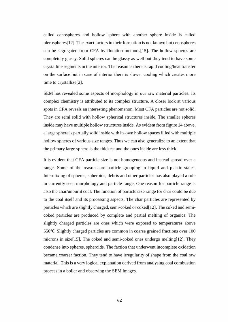
62
called cenospheres and hollow sphere with another sphere inside is called
plerospheres[12]. The exact factors in their formation is not known but cenospheres
can be segregated from CFA by flotation methods[15]. The hollow spheres are
completely glassy. Solid spheres can be glassy as well but they tend to have some
crystalline segments in the interior. The reason is there is rapid cooling/heat transfer
on the surface but in case of interior there is slower cooling which creates more
time to crystallize[2].
SEM has revealed some aspects of morphology in our raw material particles. Its
complex chemistry is attributed to its complex structure. A closer look at various
spots in CFA reveals an interesting phenomenon. Most CFA particles are not solid.
They are semi solid with hollow spherical structures inside. The smaller spheres
inside may have multiple hollow structures inside. As evident from figure 14 above,
a large sphere is partially solid inside with its own hollow spaces filled with multiple
hollow spheres of various size ranges. Thus we can also generalize to an extent that
the primary large sphere is the thickest and the ones inside are less thick.
It is evident that CFA particle size is not homogeneous and instead spread over a
range. Some of the reasons are particle grouping in liquid and plastic states.
Intermixing of spheres, spheroids, debris and other particles has also played a role
in currently seen morphology and particle range. One reason for particle range is
also the char/unburnt coal. The function of particle size range for char could be due
to the coal itself and its processing aspects. The char particles are represented by
particles which are slightly charged, semi-coked or coked[12]. The coked and semi-
coked particles are produced by complete and partial melting of organics. The
slightly charged particles are ones which were exposed to temperatures above
550℃. Slightly charged particles are common in coarse grained fractions over 100
microns in size[15]. The coked and semi-coked ones undergo melting[12]. They
condense into spheres, spheroids. The faction that underwent incomplete oxidation
became coarser faction. They tend to have irregularity of shape from the coal raw
material. This is a very logical explanation derived from analysing coal combustion
process in a boiler and observing the SEM images.

63
4.1.4 XRD Analysis
Figure 15: CFA diffractogram
From the XRD peaks we have identified quartz (SiO2) and mullite (SiO2.Al2O3).
They tend to be the only abundant crystalline structures. The red vertical lines at
angles 26.5 and 49.9 are used to highlight quartz peaks[35]. The green lines at
angles 26.2, 35.1 and 40.7 are used to highlight mullite peaks[35]. One of the
reasons for the peaks of quartz and mullite around 26° to almost overlap is due to
presence of SiO2 components in both quartz and mullite crystals. Moreover the
placement of peaks also indicates the combustion temperature they went through.
In this case it was around 800-900℃ [115]. The broad diffraction peak between 25-
35° indicates presence of amorphous phase[34]. The literature data on SiO2 and
Al2O3 have peaks at 35 degrees [116].
4.1.5 BET Analysis
BET analysis indicate that CFA has a BET surface area of 366.73±6.67 m2/g. This
surface area is attributed to presence of a large range of particles. It also suggests

64
that CFA has a lot of small particles. Moreover it proves that CFA is not
agglomerated which exposes a lot of surface area for reaction. Hence CFA is present
as fine powder and not as granules. It reinforces previous results that CFA contains
very low moisture. Moisture tend to make CFA and zeolite like materials stick and
swell reducing overall exposed surface area. Some of the surface area is also
attributed to char and may act as semi activated carbon. This also indicates that
there is a lot of small particles below 160 microns in the CFA attributing to the
surface area. This further reinforces our findings in sieving. This also tells us why
sieving was not effective to remove more carbon.
4.2 Zeolite
4.2.1 Zeolite Synthesis process
The initial batch composition plays a very crucial role to determine the kind of
framework we attempt to get hence that was taken care by use of combinatorial
approach with our assumption technique described in the experimental section.
Ageing is a tool to control product phase purity and crystal size. Batch ageing is a
suitable approach to generate nuclei by itself for the upcoming crystallization and
growth process. Long ageing periods leads to formation of greater number of nuclei.
This results in smaller crystal size leading to higher surface areas. This also leads
to greater acceleration of crystallization in later steps. In our case we opted for room
temperature ageing of 24 hours at 21℃. This is best suited for FAU type
frameworks and NaX zeolite as concluded from literature[30].
Implementing a batch ageing has a distinct advantage of not using expensive
structure directing agents or templates[30]. Hence there are cost and disposal
advantages.
The use of water in hydrothermal method is of paramount importance. The amount
of water determines the specific type of zeolite. Thus the concentrations of reactants
are varied with water quantity. Typically dilution of the gel mixture causes lower
supersaturation[30]. Crystal growth is favoured instead of nucleation resulting in
large crystals with low surface area[30]. Hence to avoid this, requisite quantities of
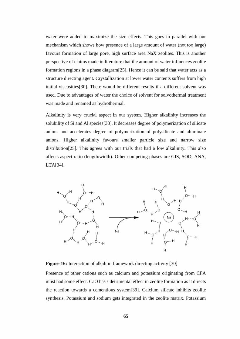
65
water were added to maximize the size effects. This goes in parallel with our
mechanism which shows how presence of a large amount of water (not too large)
favours formation of large pore, high surface area NaX zeolites. This is another
perspective of claims made in literature that the amount of water influences zeolite
formation regions in a phase diagram[25]. Hence it can be said that water acts as a
structure directing agent. Crystallization at lower water contents suffers from high
initial viscosities[30]. There would be different results if a different solvent was
used. Due to advantages of water the choice of solvent for solvothermal treatment
was made and renamed as hydrothermal.
Alkalinity is very crucial aspect in our system. Higher alkalinity increases the
solubility of Si and Al species[38]. It decreases degree of polymerization of silicate
anions and accelerates degree of polymerization of polysilicate and aluminate
anions. Higher alkalinity favours smaller particle size and narrow size
distribution[25]. This agrees with our trials that had a low alkalinity. This also
affects aspect ratio (length/width). Other competing phases are GIS, SOD, ANA,
LTA[34].
Figure 16: Interaction of alkali in framework directing activity [30]
Presence of other cations such as calcium and potassium originating from CFA
must had some effect. CaO has s detrimental effect in zeolite formation as it directs
the reaction towards a cementious system[39]. Calcium silicate inhibits zeolite
synthesis. Potassium and sodium gets integrated in the zeolite matrix. Potassium
66
takes free spots of cations for charge balance. The charges of potassium and sodium
are different thus it may upset the overall charge stability. But the quantity of excess
potassium is so small that there is minimal effect (if any).
The presence of iron brings down the strength of framework and decreases stability.
Hence high iron content zeolite is not ideal for high temperature applications such
as steam reforming etc[32]. The last paragraphs provide vital highlights about
undesirable elements in CFA mix and their possible effects during synthesis. The
last paragraphs can be considered part of descriptive error analysis.
The overall reaction kinetics would be hard to generalize because of the complex
chemistry and morphology of CFA. The rates of dissolution would be slower when
alkali attacks the outer sphere compared to inner spheres. As there is partial vacuum
inside the spheres thus rate of reaction accelerates and there is rapid dissolution of
inner sphere(s). Thus the only way to fine tune the above competing factors is to
optimize the experiments as done by us.
We also conclude that reactivity of amorphous CFA is uniform as it gives pure
zeolite. If the reactivity level was stark then we would surely get a mix of different
zeolites.
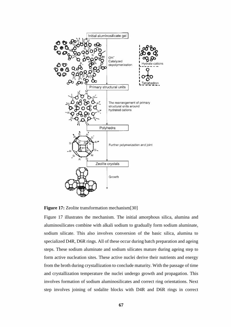
67
Figure 17: Zeolite transformation mechanism[30]
Figure 17 illustrates the mechanism. The initial amorphous silica, alumina and
aluminosilicates combine with alkali sodium to gradually form sodium aluminate,
sodium silicate. This also involves conversion of the basic silica, alumina to
specialized D4R, D6R rings. All of these occur during batch preparation and ageing
steps. These sodium aluminate and sodium silicates mature during ageing step to
form active nucleation sites. These active nuclei derive their nutrients and energy
from the broth during crystallization to conclude maturity. With the passage of time
and crystallization temperature the nuclei undergo growth and propagation. This
involves formation of sodium aluminosilicates and correct ring orientations. Next
step involves joining of sodalite blocks with D4R and D6R rings in correct
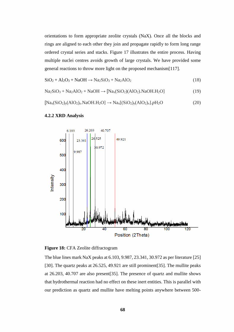
68
orientations to form appropriate zeolite crystals (NaX). Once all the blocks and
rings are aligned to each other they join and propagate rapidly to form long range
ordered crystal series and stacks. Figure 17 illustrates the entire process. Having
multiple nuclei centres avoids growth of large crystals. We have provided some
general reactions to throw more light on the proposed mechanism[117].
SiO2 + Al2O3 + NaOH → Na2SiO3 + Na2AlO2 (18)
Na2SiO3 + Na2AlO2 + NaOH → [Nax(SiO2)(AlO2).NaOH.H2O] (19)
[Nax(SiO2)y(AlO2)z.NaOH.H2O] → Nax[(SiO2)y(AlO2)x].pH2O (20)
4.2.2 XRD Analysis
Figure 18: CFA Zeolite diffractogram
The blue lines mark NaX peaks at 6.103, 9.987, 23.341, 30.972 as per literature [25]
[30]. The quartz peaks at 26.525, 49.921 are still prominent[35]. The mullite peaks
at 26.203, 40.707 are also present[35]. The presence of quartz and mullite shows
that hydrothermal reaction had no effect on these inert entities. This is parallel with
our prediction as quartz and mullite have melting points anywhere between 500-
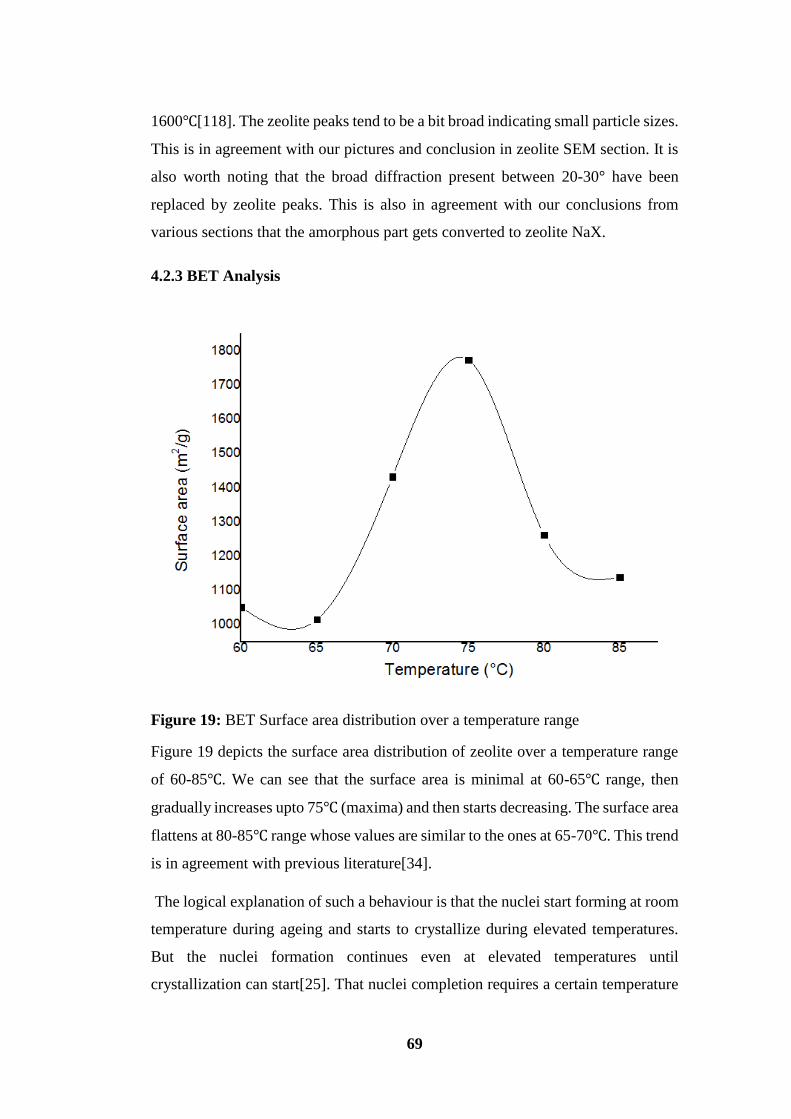
69
1600℃[118]. The zeolite peaks tend to be a bit broad indicating small particle sizes.
This is in agreement with our pictures and conclusion in zeolite SEM section. It is
also worth noting that the broad diffraction present between 20-30° have been
replaced by zeolite peaks. This is also in agreement with our conclusions from
various sections that the amorphous part gets converted to zeolite NaX.
4.2.3 BET Analysis
Figure 19: BET Surface area distribution over a temperature range
Figure 19 depicts the surface area distribution of zeolite over a temperature range
of 60-85℃. We can see that the surface area is minimal at 60-65℃ range, then
gradually increases upto 75℃ (maxima) and then starts decreasing. The surface area
flattens at 80-85℃ range whose values are similar to the ones at 65-70℃. This trend
is in agreement with previous literature[34].
The logical explanation of such a behaviour is that the nuclei start forming at room
temperature during ageing and starts to crystallize during elevated temperatures.
But the nuclei formation continues even at elevated temperatures until
crystallization can start[25]. That nuclei completion requires a certain temperature

70
which is 60-65℃ for a certain period of time. After 60-65℃ the onset of
crystallization takes place which involves the growth of these nuclei into full-
fledged crystalline structures (growth and propagation). The optimum growth and
propagation requires elevated temperatures, which is 75℃ in our case. As the
temperature reading depends on where the sensor is kept inside the oven hence we
can safely say that the optimum temperature is 75℃ ±3 (the oven was calibrated as
such).
Growth and propagation also occur at 60-65℃ range but their rate is less which
translates to less energy supply in that specific time interval of 24h[30]. It is
theoretically possible that better crystallization may occur at longer intervals[44].
But it would also lead to development of mixed phase zeolites of similar nature
[119]. The more matures nuclei will transform faster to zeolite phase NaX and with
time they will transform to next phase[44]. Hence this approach was not taken.
For the crystallizations taking place at higher than optimum temperature there is
another phenomenon. In such scenarios the crystal growth is accelerated from the
beginning leading to joining of nearby small crystals to form large size crystals[62].
Higher temperature leads to supply of higher energy for the nutrients in the media.
This phenomenon continues throughout the mix leading to larger crystal size.
Applying lesser time would lead to immature termination of crystallization leading
to many unused active spots[62]. Larger crystal size leads to smaller surface area.
In another perspective it can also be said that there is less number of crystals for the
same mass. The BET surface areas correlate to adsorption capacities which has been
verified by third party tests.
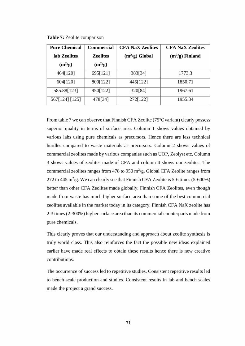
71
Table 7: Zeolite comparison
Pure Chemical
lab Zeolites
(m2/g)
Commercial
Zeolites
(m2/g)
CFA NaX Zeolites
(m2/g) Global
CFA NaX Zeolites
(m2/g) Finland
464[120] 695[121] 383[34] 1773.3
604[120] 800[122] 445[122] 1850.71
585.88[123] 950[122] 320[84] 1967.61
567[124] [125] 478[34] 272[122] 1955.34
From table 7 we can observe that Finnish CFA Zeolite (75℃ variant) clearly possess
superior quality in terms of surface area. Column 1 shows values obtained by
various labs using pure chemicals as precursors. Hence there are less technical
hurdles compared to waste materials as precursors. Column 2 shows values of
commercial zeolites made by various companies such as UOP, Zeolyst etc. Column
3 shows values of zeolites made of CFA and column 4 shows our zeolites. The
commercial zeolites ranges from 478 to 950 m2/g. Global CFA Zeolite ranges from
272 to 445 m2/g. We can clearly see that Finnish CFA Zeolite is 5-6 times (5-600%)
better than other CFA Zeolites made globally. Finnish CFA Zeolites, even though
made from waste has much higher surface area than some of the best commercial
zeolites available in the market today in its category. Finnish CFA NaX zeolite has
2-3 times (2-300%) higher surface area than its commercial counterparts made from
pure chemicals.
This clearly proves that our understanding and approach about zeolite synthesis is
truly world class. This also reinforces the fact the possible new ideas explained
earlier have made real effects to obtain these results hence there is new creative
contributions.
The occurrence of success led to repetitive studies. Consistent repetitive results led
to bench scale production and studies. Consistent results in lab and bench scales
made the project a grand success.

72
4.2.4 SEM Analysis
Figure 20: Overview of CFA Zeolite conversion
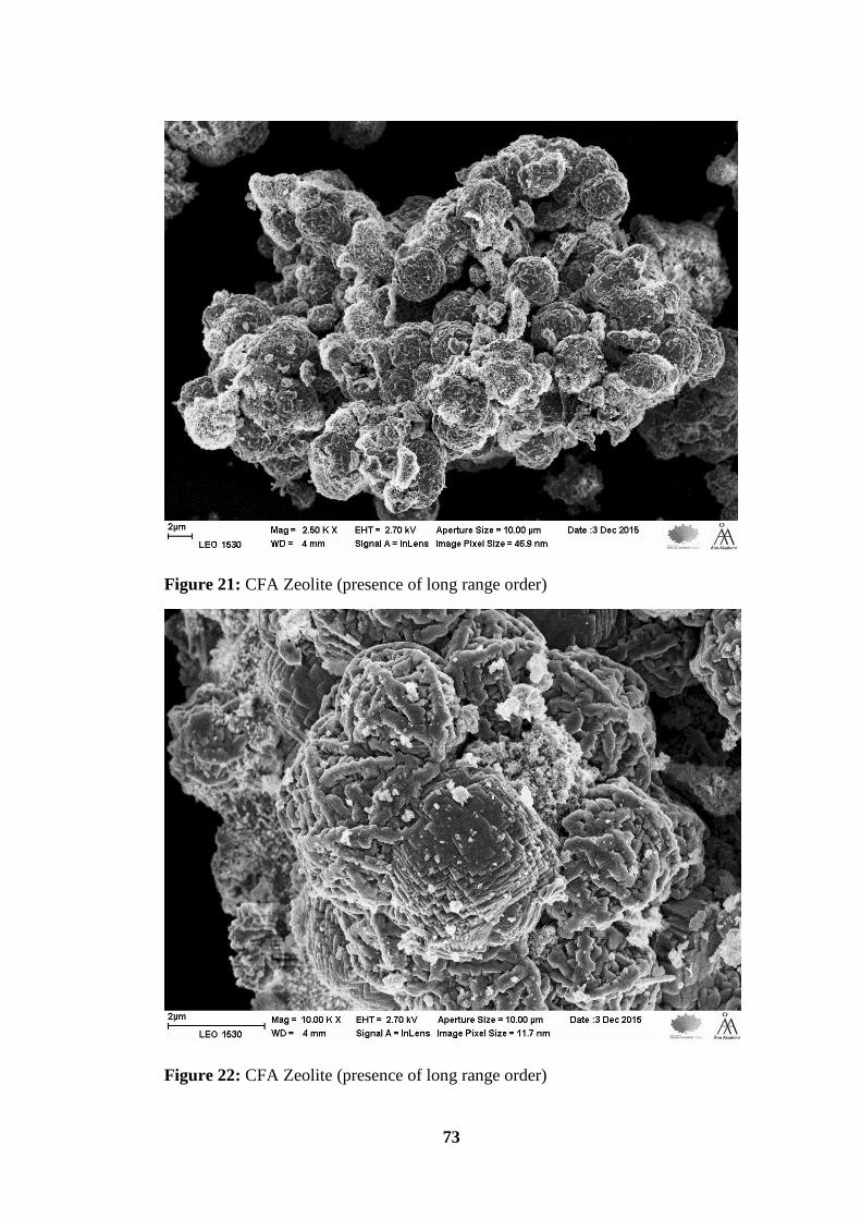
73
Figure 21: CFA Zeolite (presence of long range order)
Figure 22: CFA Zeolite (presence of long range order)

74
Figure 23: Zeolite inside a hollow sphere with quartz outer shell
Figure 24: CFA Zeolite (proof of semi vacuum approach)
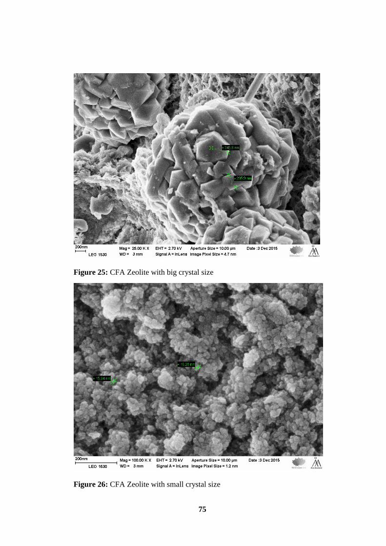
75
Figure 25: CFA Zeolite with big crystal size
Figure 26: CFA Zeolite with small crystal size

76
The images shows that the particles are distinctly different from CFA. This provides
visual conformation that there has been reaction on CFA particles to yield zeolite
products. It is clear that zeolites formed are porous, crystalline with layered
structure. Images illustrate that conversion and surface coverage is totally
homogenous indicating that all of the glass has been converted to zeolite. The extent
of conversion is also visible into the inner structure of CFA as many spheres have
exploded and its inner materials converted to zeolites (figures 23, 24). The zeolite
appears to be an ordered and crystalline structure (figures 20, 21, 22, 25, 26). The
presence of long range order is clearly visible from the stacks/apartment floor like
structures of zeolite clusters (figure 22). This is reinforced by XRD data as well.
Figure 22 indicate that crystallization and propagation has occurred in a linear
trajectory which reinforces our claim of layered structures in the bulk solid. Figures
22, 24 clearly illustrates that CFA skeletal collapse of amorphous part. The outer
glassy part converted to zeolite indicated by the semi-linear trajectory. Moreover
the presence of semi-vacuum inside the CFA spheres has accelerated rate of
reaction by luring alkali deep inside hollow spheres and allowing rapid reaction.
The partial vacuum plays a role in sucking the alkali once the outer structure
collapsed completely or partially (figure 23). This is support of our semi-vacuum
theory can be found in figure 23 where the outer hollow sphere is quartz with some
reaction spots indicating zeolite centres. Those zeolite centres were amorphous
glass. The dissolution of the spots led to exposure of vacuum where the alkali
rushed in to fill the void and reacted with inner glass to synthesis zeolites. The
effects of small sizes would be clearly reflected in very high BET surface area
values and high application/adsorption capacity in field tests. As the particle size
varies hence certain part of the sample will have higher surface area/application
capacity than other part of the same powder mix. The size distribution is also quite
varied (figures 25, 26). The various images clearly indicate that size distribution
ranges from 345 nm to 16 nm.
It is quite evident that majority of CFA was amorphous material which led to zeolite
synthesis. This is turn supports our previous claim of CFA XRD analysis which
ascertains amorphous content as majority stake in CFA.
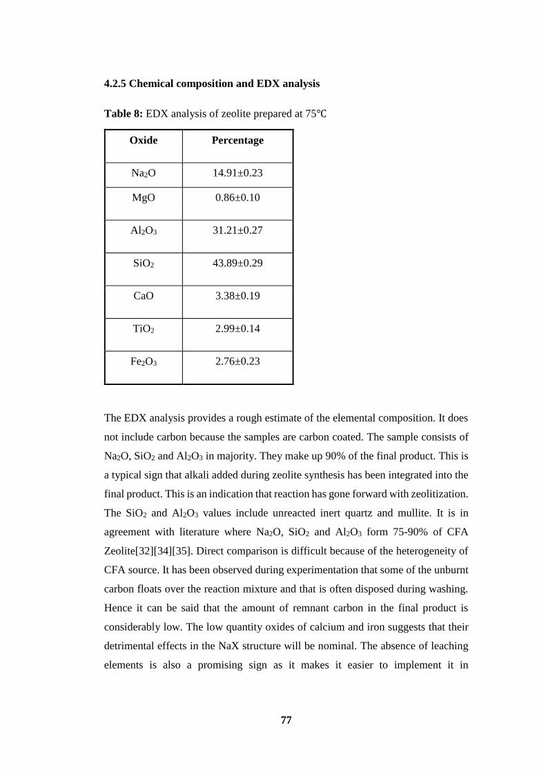
77
4.2.5 Chemical composition and EDX analysis
Table 8: EDX analysis of zeolite prepared at 75℃
Oxide Percentage
Na2O 14.91±0.23
MgO 0.86±0.10
Al2O3 31.21±0.27
SiO2 43.89±0.29
CaO 3.38±0.19
TiO2 2.99±0.14
Fe2O3 2.76±0.23
The EDX analysis provides a rough estimate of the elemental composition. It does
not include carbon because the samples are carbon coated. The sample consists of
Na2O, SiO2 and Al2O3 in majority. They make up 90% of the final product. This is
a typical sign that alkali added during zeolite synthesis has been integrated into the
final product. This is an indication that reaction has gone forward with zeolitization.
The SiO2 and Al2O3 values include unreacted inert quartz and mullite. It is in
agreement with literature where Na2O, SiO2 and Al2O3 form 75-90% of CFA
Zeolite[32][34][35]. Direct comparison is difficult because of the heterogeneity of
CFA source. It has been observed during experimentation that some of the unburnt
carbon floats over the reaction mixture and that is often disposed during washing.
Hence it can be said that the amount of remnant carbon in the final product is
considerably low. The low quantity oxides of calcium and iron suggests that their
detrimental effects in the NaX structure will be nominal. The absence of leaching
elements is also a promising sign as it makes it easier to implement it in
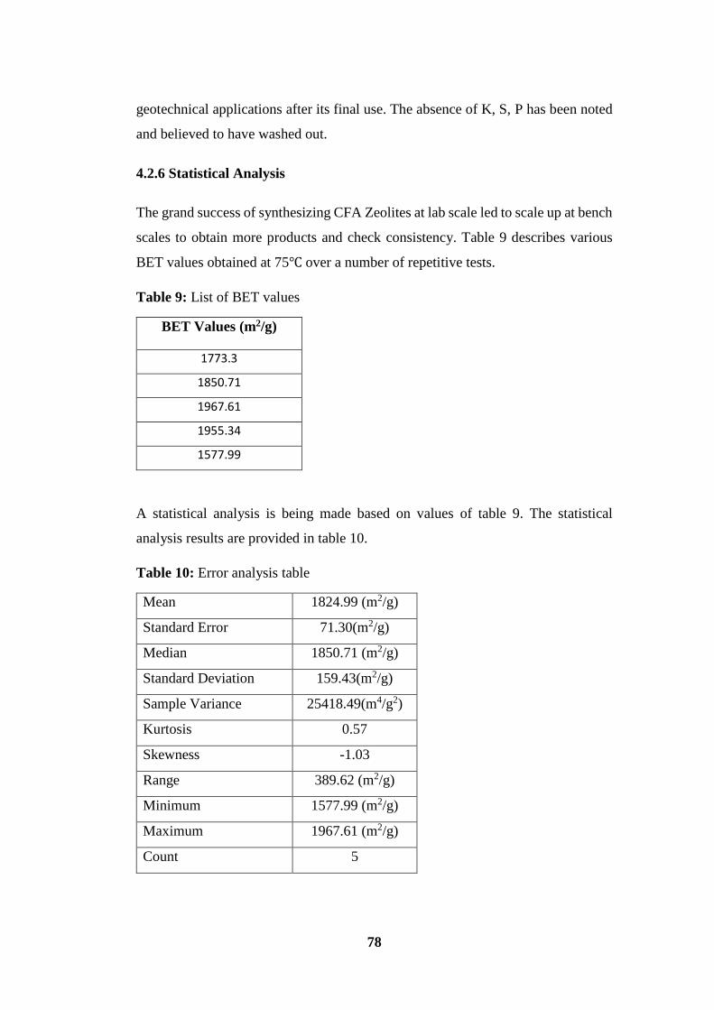
78
geotechnical applications after its final use. The absence of K, S, P has been noted
and believed to have washed out.
4.2.6 Statistical Analysis
The grand success of synthesizing CFA Zeolites at lab scale led to scale up at bench
scales to obtain more products and check consistency. Table 9 describes various
BET values obtained at 75℃ over a number of repetitive tests.
Table 9: List of BET values
BET Values (m2/g)
1773.3
1850.71
1967.61
1955.34
1577.99
A statistical analysis is being made based on values of table 9. The statistical
analysis results are provided in table 10.
Table 10: Error analysis table
Mean 1824.99 (m2/g)
Standard Error 71.30(m2/g)
Median 1850.71 (m2/g)
Standard Deviation 159.43(m2/g)
Sample Variance 25418.49(m4/g2)
Kurtosis 0.57
Skewness -1.03
Range 389.62 (m2/g)
Minimum 1577.99 (m2/g)
Maximum 1967.61 (m2/g)
Count 5
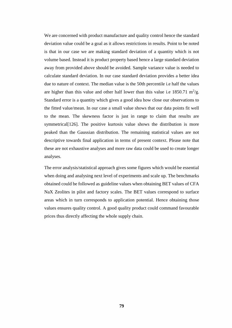
79
We are concerned with product manufacture and quality control hence the standard
deviation value could be a goal as it allows restrictions in results. Point to be noted
is that in our case we are making standard deviation of a quantity which is not
volume based. Instead it is product property based hence a large standard deviation
away from provided above should be avoided. Sample variance value is needed to
calculate standard deviation. In our case standard deviation provides a better idea
due to nature of context. The median value is the 50th percentile i.e half the values
are higher than this value and other half lower than this value i.e 1850.71 m2/g.
Standard error is a quantity which gives a good idea how close our observations to
the fitted value/mean. In our case a small value shows that our data points fit well
to the mean. The skewness factor is just in range to claim that results are
symmetrical[126]. The positive kurtosis value shows the distribution is more
peaked than the Gaussian distribution. The remaining statistical values are not
descriptive towards final application in terms of present context. Please note that
these are not exhaustive analyses and more raw data could be used to create longer
analyses.
The error analysis/statistical approach gives some figures which would be essential
when doing and analysing next level of experiments and scale up. The benchmarks
obtained could be followed as guideline values when obtaining BET values of CFA
NaX Zeolites in pilot and factory scales. The BET values correspond to surface
areas which in turn corresponds to application potential. Hence obtaining those
values ensures quality control. A good quality product could command favourable
prices thus directly affecting the whole supply chain.

80
5 CONCLUSIONS
CFA has been analysed and classified as F-Class, medium grade. The complexity
of CFA makes its accurate quantification very difficult. CFA primarily consists of
SiO2, Al2O3 and Fe2O3 combined to give 85.43% weight basis. Part of SiO2 and
Al2O3 is amorphous and rest is crystalline quartz and mullite. Crystalline phases are
being detected by XRD analysis. LOI is 4.57% with sieving retrieval of 0.2%
weight basis. The presence of CaO and Fe2O3 is a cause for concern whereas the
lack of toxic leachable elements is a cause of rejoice. CFA has spherical
morphology consisting of cenospheres and plerospheres which have a wide particle
range. Majority mass of the particles are less than 160 microns and they are
reflected through sieving experiments and BET value of 366.73 m2/g which is an
above average number for CFA. Overall CFA has very low moisture content of
0.13% weight basis with great practical implications. The amorphous and
crystalline phase dwell among each other and the presence of exclusive spots are
not found. However a hollow sphere can be crystalline on the outside but
amorphous in the inside has been reported through zeolite growth studies and
observance through SEM for the first time. Careful analysis of CFA has led to other
new insights especially in relation to CFA combustion and final morphology which
would be beneficial for other researchers.
CFA Zeolite has been synthesized by hydrothermal method with combinatorial
approach. The process involves batch composition design, ageing for 24h at 21℃
with 650 rpm. This is followed by hydrothermal treatment for 24h between 60-85℃.
The optimum results were obtained at 75℃ . We did not use any expensive structure
directing agents or templating agents. Thus saving costs and disposal issues. To
achieve the correct batch composition, rational mass experiment design with
combinatorial approach as taken. The logical design involved use of various phase
diagrams. A new experimental approach to find appropriate CFA Zeolitization
reactive parts due to lack of instrumental quantification was developed. A new idea
was proposed where CFA particles are semi-vacuum and alkaline activated
thereafter. The new concept also highlights how and why alkali would penetrate
inside spheres and synthesize zeolites. An overall mechanism was also proposed
81
with reaction equations which make the process clear to the next researcher. This
was supported by explanations of the structure and chemistry involved. Focus was
made on creating zeolites with high surface area and that was achieved by
appropriate theoretical approach and experimental fine tuning. Detailed
explanations were provided for the effect of temperature on morphology
development. Instrumental analysis by SEM, EDX, XRD and BET confirms the
product as CFA Zeolite with pure NaX phase only. It is a key achievement that only
pure phase NaX zeolite has been created instead of mixed phase zeolites. Literature
indicates using waste as raw materials and hydrothermal approach often yields mix
of NaX with competing phases of LTA, SOD, GIS etc. Instrumental analysis also
prove that NaX zeolite is highly crystalline with long range order. Various
techniques reinforce each other in claims. CFA Zeolites have a particle range of
345 nm to 16 nm which has been reflected in very high BET surface area values.
The approximate values range from 1800-2000 m2/g. Such values have been
reported for the first time in the world.
Thus a very indept understanding of zeolites and synthesis process led to a simple,
green, eco-friendly, cheap and scalable process. Excellent understanding of
materials chemistry played a key role in designing the whole concept which
emphasized on self-activation rather than SDA oriented development. The core of
our idea was circular economy and green synthesis and use of SDAs such a TMA
which are hazardous flammable chemicals with disposal issues were avoided.
Once a new material is developed it is essential to ascertain repeatability, maintain
standards and quality control. Hence multiple repetition studies were done in lab
scale and bench scale. In lab scale we were producing 2.0g sample and we scaled
to bench level to produce 100g samples. BET analysis at both levels were made to
obtain a lot of data, that data was made subject to statistical and error analysis.
Certain benchmarks and small guidelines were developed which could be followed
in the future for manufacture and quality control.

82
6 FUTURE WORK
Future work involves:
Scaling up the process to pilot scale.
Identification and use of grinding equipment for powdering of large scale
zeolites during the post drying phase.
Quantification and utilization of waste heat produced during pilot studies.
Try other CFA obtained from other operational power plants in Finland.
Use of older silo stockpiled CFA and check if that could be an added source
of raw material.
Diversify by utilizing other raw materials such as silica, aluminium and
caustic soda industry side streams.
Develop more quality control guidelines for the above mentioned ideas.
Utilize the broad range of data from above initiatives to create an interactive
real time database/app which provides instant process parameters for zeolite
production using ashes or other side streams.
The above vision takes into account circular economy, digitalization and
internet of things for a truly sustainable future.
Creation of a network of ash modification and waste to value plants which
produce zeolite among their commercial products.
REFERENCES
[1] C. Heidrich, H.-J. Feuerborn, and A. Weir, “Coal combustion products. A
global perspective,” VGB PowerTech, vol. 93, no. 12, pp. 46–52, 2013.
[2] R. S. Blissett and N. A. Rowson, “A review of the multi-component utilisation
of coal fly ash,” Fuel, vol. 97, pp. 1–23, Jul. 2012.
[3] M. Basu, M. Pande, P. B. S. Bhadoria, and S. C. Mahapatra, “Potential fly-ash
utilization in agriculture: A global review,” Prog. Nat. Sci., vol. 19, no. 10, pp.
1173–1186, Oct. 2009.
[4] “Resources,” World Coal Association. [Online]. Available:
http://www.worldcoal.org/resources. [Accessed: 06-Mar-2016].
[5] R. S.-M. Newspapers, “Study of coal ash sites finds extensive water
contamination,” mcclatchydc. [Online]. Available:
http://www.mcclatchydc.com/news/nation-
world/national/article24591235.html. [Accessed: 06-Mar-2016].

83
[6] R. Kikuchi, “Application of coal ash to environmental improvement:
Transformation into zeolite, potassium fertilizer, and FGD absorbent,” Resour.
Conserv. Recycl., vol. 27, no. 4, pp. 333–346, Oct. 1999.
[7] A. B. Mukherjee and R. Kikuchi, “Coal Ash from Thermal Power Plants in
Finland,” in Biogeochemistry of Trace Elements in Coal and Coal Combustion
Byproducts, K. S. Sajwan, A. K. Alva, and R. F. Keefer, Eds. Springer US,
1999, pp. 59–76.
[8] “Zeolite | Sigma-Aldrich.” [Online]. Available:
http://www.sigmaaldrich.com/catalog/product/sigma/96096?lang=fi®ion=
FI. [Accessed: 30-Mar-2016].
[9] S. V. Vassilev and C. G. Vassileva, “Methods for Characterization of
Composition of Fly Ashes from Coal-Fired Power Stations: A Critical
Overview,” Energy Fuels, vol. 19, no. 3, pp. 1084–1098, May 2005.
[10] M. A. Rajabzadeh, Z. Ghorbani, and B. Keshavarzi, “Chemistry,
mineralogy and distribution of selected trace-elements in the Parvadeh coals,
Tabas, Iran,” Fuel, vol. 174, pp. 216–224, Jun. 2016.
[11] F. Goodarzi, “Mineralogy, elemental composition and modes of occurrence
of elements in Canadian feed-coals,” Fuel, vol. 81, no. 9, pp. 1199–1213, Jun.
2002.
[12] S. V. Vassilev and C. G. Vassileva, “Mineralogy of combustion wastes from
coal-fired power stations,” Fuel Process. Technol., vol. 47, no. 3, pp. 261–280,
Jun. 1996.
[13] Y. Li, X. Gao, and H. Wu, “Further Investigation into the Formation
Mechanism of Ash Cenospheres from an Australian Coal-Fired Power Station,”
Energy Fuels, vol. 27, no. 2, pp. 811–815, Feb. 2013.
[14] E. V. Sokol, N. V. Maksimova, N. I. Volkova, E. N. Nigmatulina, and A. E.
Frenkel, “Hollow silicate microspheres from fly ashes of the Chelyabinsk
brown coals (South Urals, Russia),” Fuel Process. Technol., vol. 67, no. 1, pp.
35–52, Jun. 2000.
[15] S. V. Vassilev and C. G. Vassileva, “A new approach for the classification
of coal fly ashes based on their origin, composition, properties, and behaviour,”
Fuel, vol. 86, no. 10–11, pp. 1490–1512, Jul. 2007.
[16] J. Jankowski, C. R. Ward, D. French, and S. Groves, “Mobility of trace
elements from selected Australian fly ashes and its potential impact on aquatic
ecosystems,” Fuel, vol. 85, no. 2, pp. 243–256, Jan. 2006.
[17] R. H. Matjie, Z. Li, C. R. Ward, J. Kosasi, J. R. Bunt, and C. A. Strydom,
“Mineralogy of Furnace Deposits Produced by South African Coals during
Pulverized-Fuel Combustion Tests,” Energy Fuels, vol. 29, no. 12, pp. 8226–
8238, Dec. 2015.
[18] S. Wang, “Application of Solid Ash Based Catalysts in Heterogeneous
Catalysis,” Environ. Sci. Technol., vol. 42, no. 19, pp. 7055–7063, Oct. 2008.
[19] M. Erol, S. Küçükbayrak, and A. Ersoy-Meriçboyu, “Comparison of the
properties of glass, glass-ceramic and ceramic materials produced from coal fly
ash,” J. Hazard. Mater., vol. 153, no. 1–2, pp. 418–425, May 2008.
[20] D. J. M. Flower and J. G. Sanjayan, “Green house gas emissions due to
concrete manufacture,” Int. J. Life Cycle Assess., vol. 12, no. 5, pp. 282–288,
May 2007.

84
[21] M. Reiner and K. Rens, “High-Volume Fly Ash Concrete: Analysis and
Application,” Pract. Period. Struct. Des. Constr., vol. 11, no. 1, pp. 58–64, Feb.
2006.
[22] J. C. Swanepoel and C. A. Strydom, “Utilisation of fly ash in a
geopolymeric material,” Appl. Geochem., vol. 17, no. 8, pp. 1143–1148, Aug.
2002.
[23] P. Kumar, N. Mal, Y. Oumi, K. Yamana, and T. Sano, “Mesoporous
materials prepared using coal fly ash as the silicon and aluminium source,” J.
Mater. Chem., vol. 11, no. 12, pp. 3285–3290, Nov. 2001.
[24] J.-P. G. Michel Guisnet, “Zeolites for Cleaner Technologies,” 2005.
[25] D. W. Breck, Zeolite molecular sieves: structure, chemistry, and use. New
York: Wiley, 1973.
[26] H.-J. Arpe, Water to Zirconium and Zirconium Compounds, Volume A28,
Ullmann’s Encyclopedia of Industrial Chemistry, 5 edition. Wiley-VCH, 1996.
[27] “Framework Type.” [Online]. Available: http://izasc.fos.su.se/fmi/xsl/IZA-
SC/ft.xsl. [Accessed: 21-Mar-2016].
[28] C. S. Cundy and P. A. Cox, “The hydrothermal synthesis of zeolites:
Precursors, intermediates and reaction mechanism,” Microporous Mesoporous
Mater., vol. 82, no. 1–2, pp. 1–78, Jul. 2005.
[29] A. D. Elliot, “An investigation into the hydrothermal processing of coal fly
ash to produce zeolite for controlled release fertiliser applications,” 2006.
[30] J. Cejka, H. van Bekkum, A. Corma, and F. Schueth, Introduction to Zeolite
Molecular Sieves. Elsevier, 2007.
[31] “FAU.” [Online]. Available: http://izasc.fos.su.se/fmi/xsl/IZA-
SC/ftc_fw.xsl?-db=Atlas_main&-lay=fw&-max=25&STC=FAU&-find.
[Accessed: 21-Mar-2016].
[32] X. Querol, N. Moreno, J. C. Umaña, A. Alastuey, E. Hernández, A. López-
Soler, and F. Plana, “Synthesis of zeolites from coal fly ash: an overview,” Int.
J. Coal Geol., vol. 50, no. 1–4, pp. 413–423, May 2002.
[33] S. Feng and R. Xu, “New materials in hydrothermal synthesis,” Acc. Chem.
Res., vol. 34, no. 3, pp. 239–247, Mar. 2001.
[34] K. Ojha, N. C. Pradhan, and A. N. Samanta, “Zeolite from fly ash: synthesis
and characterization,” Bull. Mater. Sci., vol. 27, no. 6, pp. 555–564, Dec. 2004.
[35] G. Das, N. C. Pradhan, G. M. Madhu, and H. S. Preetham, “Removal of
Cadmium from Aqueous Streams by Zeolite Synthesized from Fly Ash.”
[36] W. Xu, J. Dong, J. Li, J. Li, and F. Wu, “A novel method for the preparation
of zeolite ZSM-5,” J. Chem. Soc. Chem. Commun., no. 10, pp. 755–756, Jan.
1990.
[37] N. Takako, I. Takuji, A. Chie, H. Yasuhisa, K. Yoshimichi, and H. Takaaki,
“Solvothermal Synthesis of −LIT-type Zeolite,” Cryst. Growth Des., vol. 12,
no. 4, pp. 1752–1761, Apr. 2012.
[38] T. Wajima, K. Yoshizuka, T. Hirai, and Y. Ikegami, “Synthesis of Zeolite
X from Waste Sandstone Cake Using Alkali Fusion Method,” Mater. Trans.,
vol. 49, no. 3, pp. 612–618, 2008.
[39] X. Querol, A. Alastuey, A. López-Soler, F. Plana, J. M. Andrés, R. Juan, P.
Ferrer, and C. R. Ruiz, “A Fast Method for Recycling Fly Ash: Microwave-
Assisted Zeolite Synthesis,” Environ. Sci. Technol., vol. 31, no. 9, pp. 2527–
2533, Sep. 1997.
85
[40] M. Inada, H. Tsujimoto, Y. Eguchi, N. Enomoto, and J. Hojo, “Microwave-
assisted zeolite synthesis from coal fly ash in hydrothermal process,” Fuel, vol.
84, no. 12–13, pp. 1482–1486, Sep. 2005.
[41] D. Akporiaye, I. M. Dahl, A. Karlsson, and R. Wendelbo, “Multiautoclave
for combinatorial synthesis of zeolites and other materials,” US6821486 B1,
23-Nov-2004.
[42] D. E. Akporiaye, I. M. Dahl, A. Karlsson, and R. Wendelbo, “Combinatorial
Approach to the Hydrothermal Synthesis of Zeolites,” Angew. Chem. Int. Ed.,
vol. 37, no. 5, pp. 609–611, Mar. 1998.
[43] D. E. Akporiaye, “Towards a Rational Synthesis of Large-Pore Zeolite-
Type Materials?,” Angew. Chem. Int. Ed., vol. 37, no. 18, pp. 2456–2457, Oct.
1998.
[44] C. S. Cundy and P. A. Cox, “The Hydrothermal Synthesis of Zeolites:
History and Development from the Earliest Days to the Present Time,” Chem.
Rev., vol. 103, no. 3, pp. 663–702, Mar. 2003.
[45] J. Yu and R. Xu, “Rational Approaches toward the Design and Synthesis of
Zeolitic Inorganic Open-Framework Materials,” Acc. Chem. Res., vol. 43, no.
9, pp. 1195–1204, Sep. 2010.
[46] E. R. Parnham and R. E. Morris, “Ionothermal Synthesis of Zeolites, Metal–
Organic Frameworks, and Inorganic–Organic Hybrids,” Acc. Chem. Res., vol.
40, no. 10, pp. 1005–1013, Oct. 2007.
[47] A. Rojas, E. Martínez-Morales, C. M. Zicovich-Wilson, and M. A.
Camblor, “Zeolite Synthesis in Fluoride Media: Structure Direction toward
ITW by Small Methylimidazolium Cations,” J. Am. Chem. Soc., vol. 134, no.
4, pp. 2255–2263, Feb. 2012.
[48] J. Zhang, W. Yan, H. Ding, Y. Liu, K. Tang, J. Yu, and R. Xu,
“Microemulsion-directed synthesis of zeolite A nano-crystals,” in Studies in
Surface Science and Catalysis, vol. 170, Z. G. Ruren Xu Jiesheng Chen and
Wenfu Yan, Ed. Elsevier, 2007, pp. 475–479.
[49] S. P. Naik, A. S. T. Chiang, and R. W. Thompson, “Synthesis of Zeolitic
Mesoporous Materials by Dry Gel Conversion under Controlled Humidity,” J.
Phys. Chem. B, vol. 107, no. 29, pp. 7006–7014, Jul. 2003.
[50] N. M. Musyoka, L. Petrik, and E. Hums, “Synthesis of Zeolite A, X and P
from a South African Coal Fly Ash,” Adv. Mater. Res., vol. 512–515, pp. 1757–
1762, May 2012.
[51] C. I. Juliana De, “Zeolite Synthesis from Brazilian Coal Fly Ash for
Removal of Zn<sup>2 </sup> and Cd<sup>2 </sup>
from Water,” Adv. Mater. Res., vol. 356–360, 2012.
[52] H. Tanaka, A. Miyagawa, H. Eguchi, and R. Hino, “Synthesis of a Single-
Phase Na-A Zeolite from Coal Fly Ash by Dialysis,” Ind. Eng. Chem. Res., vol.
43, no. 19, pp. 6090–6094, Sep. 2004.
[53] B.-S. Shin, S.-O. Lee, and N.-P. Kook, “Preparation of zeolitic adsorbents
from waste coal fly ash,” Korean J. Chem. Eng., vol. 12, no. 3, pp. 352–357,
Jul. 1995.
[54] A. D. Elliot and D. Zhang, “Controlled Release Zeolite Fertilisers: A Value
Added Product Produced from Fly Ash,” ResearchGate, Jan. 2005.
[55] X. Querol, J. C. Umaña, F. Plana, A. Alastuey, A. Lopez-Soler, A.
Medinaceli, A. Valero, M. J. Domingo, and E. Garcia-Rojo, “Synthesis of

86
zeolites from fly ash at pilot plant scale. Examples of potential applications,”
Fuel, vol. 80, no. 6, pp. 857–865, May 2001.
[56] “Neyveli Lignite Corporation Limited.” [Online]. Available:
https://www.nlcindia.com/index.php?file_name=about_01n. [Accessed: 28-
Mar-2016].
[57] C. J. Rhodes, “Properties and applications of zeolites,” Sci. Prog., vol. 93,
no. Pt 3, pp. 223–284, 2010.
[58] C. J. Rhodes, “Zeolites: physical aspects and environmental applications,”
Annu. Rep. Sect. C Phys. Chem., vol. 103, no. 0, pp. 287–325, Jun. 2007.
[59] R. Jain and J. K. Tseng, “Process for argon purification,” US6113869 A,
05-Sep-2000.
[60] Tasrik, “Zeolite process for water softening,” Hard and Soft Water, 29-Jan-
2014. .
[61] N. D. Hutson, B. A. Reisner, R. T. Yang, and B. H. Toby, “Silver Ion-
Exchanged Zeolites Y, X, and Low-Silica X: Observations of Thermally
Induced Cation/Cluster Migration and the Resulting Effects on the Equilibrium
Adsorption of Nitrogen,” Chem. Mater., vol. 12, no. 10, pp. 3020–3031, Oct.
2000.
[62] L. Tosheva, A. Brockbank, B. Mihailova, J. Sutula, J. Ludwig, H. Potgieter,
and J. Verran, “Micron- and nanosized FAU-type zeolites from fly ash for
antibacterial applications,” J. Mater. Chem., vol. 22, no. 33, pp. 16897–16905,
Jul. 2012.
[63] H. Huang, X. Xiao, B. Yan, and L. Yang, “Ammonium removal from
aqueous solutions by using natural Chinese (Chende) zeolite as adsorbent,” J.
Hazard. Mater., vol. 175, no. 1–3, pp. 247–252, Mar. 2010.
[64] S. R. Hua-Jiang Huang, “A review of separation technologies in current and
future biorefineries,” Sep. Purif. Technol., no. 1, pp. 1–21, 2008.
[65] A. L. M. Shivaji Sircar, “Gas Separation by Zeolites,” 2003.
[66] J. Buckman, “Pneumatic pressure bandage for medical applications,”
US20030199922 A1, 23-Oct-2003.
[67] F. A. Mumpton, “La roca magica: Uses of natural zeolites in agriculture and
industry,” Proc. Natl. Acad. Sci., vol. 96, no. 7, pp. 3463–3470, Mar. 1999.
[68] “ORTHOCON.” [Online]. Available:
http://www.orthocon.com/product.asp. [Accessed: 31-Mar-2016].
[69] S. Rayalu, N. K. Labhasetwar, and P. Khanna, “Silica enriched fly ash based
zeolite Y for use in automotive catalytic converters,” DE19841230 A1, 03-Feb-
2000.
[70] N.-Q. Feng and G.-F. Peng, “Applications of natural zeolite to construction
and building materials in China,” Constr. Build. Mater., vol. 19, no. 8, pp. 579–
584, Oct. 2005.
[71] P. Misaelides, “Application of natural zeolites in environmental
remediation: A short review,” Microporous Mesoporous Mater., vol. 144, no.
1–3, pp. 15–18, Oct. 2011.
[72] K. Chihara, T. Aiko, T. Kaneko, S. Oda, and S. Hamashima, “Solvent
recovery by PSA with high silica zeolite: An experimental and A simulation
study,” in Studies in Surface Science and Catalysis, vol. 154, Part B, M. C. and
L. H. C. E. van Steen, Ed. Elsevier, 2004, pp. 2003–2011.
87
[73] G. P. Ansell, J. M. Fisher, P. G. Gray, H. G. C. Hamilton, and R. R. Rajaram,
“Diesel engine exhaust gas purification method,” US5943857 A, 31-Aug-1999.
[74] J. Valyon, G. Onyestyák, and L. V. C. Rees, “A Frequency-Response Study
of the Diffusion and Sorption Dynamics of Ammonia in Zeolites,” Langmuir,
vol. 16, no. 3, pp. 1331–1336, Feb. 2000.
[75] J. Čejka, Ed., Introduction to zeolite science and practice, 3rd rev. ed.
Amsterdam ; Boston: Elsevier, 2007.
[76] N. Mikio and N. M. Masaki, “Radiolytic hydrogen gas formation from water
adsorbed on type Y zeolites,” Radiat. Phys. Chem., vol. 47, no. 2, pp. 241–245,
Feb. 1996.
[77] L. Alaerts, C. E. A. Kirschhock, M. Maes, M. A. van der Veen, V. Finsy,
A. Depla, J. A. Martens, G. V. Baron, P. A. Jacobs, J. F. M. Denayer, and D. E.
De Vos, “Selective Adsorption and Separation of Xylene Isomers and
Ethylbenzene with the Microporous Vanadium(IV) Terephthalate MIL-47,”
Angew. Chem., vol. 119, no. 23, pp. 4371–4375, Jun. 2007.
[78] K. Hashimoto, S. Adachi, H. Noujima, and H. Maruyama, “Models for the
Separation of Glucose/Fructose Mixture Using a Simulated Moving-Bed
Adsorber,” J. Chem. Eng. Jpn., vol. 16, no. 5, pp. 400–406, 1983.
[79] V. Nikolakis, G. Xomeritakis, A. Abibi, M. Dickson, M. Tsapatsis, and D.
G. Vlachos, “Growth of a faujasite-type zeolite membrane and its application
in the separation of saturated/unsaturated hydrocarbon mixtures,” J. Membr.
Sci., vol. 184, no. 2, pp. 209–219, Mar. 2001.
[80] D. Kubička and O. Kikhtyanin, “Opportunities for zeolites in biomass
upgrading—Lessons from the refining and petrochemical industry,” Catal.
Today, vol. 243, pp. 10–22, Apr. 2015.
[81] A. Brito, M. E. Borges, and N. Otero, “Zeolite Y as a Heterogeneous
Catalyst in Biodiesel Fuel Production from Used Vegetable Oil,” Energy Fuels,
vol. 21, no. 6, pp. 3280–3283, Nov. 2007.
[82] I. Kubičková and D. Kubička, “Utilization of Triglycerides and Related
Feedstocks for Production of Clean Hydrocarbon Fuels and Petrochemicals: A
Review,” Waste Biomass Valorization, vol. 1, no. 3, pp. 293–308, Aug. 2010.
[83] M. Marczewski, J.-P. Bodibo, G. Perot, and M. Guisnet, “Alkylation of
aromatics,” J. Mol. Catal., vol. 50, no. 2, pp. 211–218, Mar. 1989.
[84] O. Babajide, N. Musyoka, L. Petrik, and F. Ameer, “Novel zeolite Na-X
synthesized from fly ash as a heterogeneous catalyst in biodiesel production,”
Catal. Today, vol. 190, no. 1, pp. 54–60, Aug. 2012.
[85] S. Lestari, P. Mäki-Arvela, J. Beltramini, G. Q. M. Lu, and D. Y. Murzin,
“Transforming triglycerides and fatty acids into biofuels,” ChemSusChem, vol.
2, no. 12, pp. 1109–1119, 2009.
[86] S. SARAVANAMURUGAN and A. Riisager, “Conversion of
carbohydrates to levulinic acid esters,” WO2014020153 A1, 06-Feb-2014.
[87] O. Kikhtyanin, V. Kelbichová, D. Vitvarová, M. Kubů, and D. Kubička,
“Aldol condensation of furfural and acetone on zeolites,” Catal. Today, vol.
227, pp. 154–162, May 2014.
[88] M. Şahmaran, N. Özkan, S. B. Keskin, B. Uzal, İ. Ö. Yaman, and T. K.
Erdem, “Evaluation of natural zeolite as a viscosity-modifying agent for
cement-based grouts,” Cem. Concr. Res., vol. 38, no. 7, pp. 930–937, Jul. 2008.

88
[89] R. Vidal, E. Moliner, G. Martínez, and M. C. Rubio, “Life cycle assessment
of hot mix asphalt and zeolite-based warm mix asphalt with reclaimed asphalt
pavement,” Resour. Conserv. Recycl., vol. 74, pp. 101–114, May 2013.
[90] K. A. Czurda and R. Haus, “Reactive barriers with fly ash zeolites for in situ
groundwater remediation,” Appl. Clay Sci., vol. 21, no. 1–2, pp. 13–20, Apr.
2002.
[91] M. Tao and R. Mallick, “Effects of Warm-Mix Asphalt Additives on
Workability and Mechanical Properties of Reclaimed Asphalt Pavement
Material,” Transp. Res. Rec. J. Transp. Res. Board, vol. 2126, pp. 151–160,
Dec. 2009.
[92] Unknown, “Zeolite and lime combinations for warm mix asphalt,”
CA2783644 A1, 20-Jan-2013.
[93] “WHO | Former Director-General: Dr Gro Harlem Brundtland,” WHO.
[Online]. Available: http://www.who.int/dg/brundtland/en/. [Accessed: 11-
Apr-2016].
[94] N. Nakajima, “A Vision of Industrial Ecology: State-of-the-Art Practices
for a Circular and Service-Based Economy,” Bull. Sci. Technol. Amp Soc., vol.
20, no. 1, pp. 54–69, 2000.
[95] A. Murray, K. Skene, and K. Haynes, “The Circular Economy: An
Interdisciplinary Exploration of the Concept and Application in a Global
Context,” J. Bus. Ethics, pp. 1–12, May 2015.
[96] R. Bermejo, “Circular Economy: Materials Scarcity, European Union
Policy and Foundations of a Circular Economy,” in Handbook for a Sustainable
Economy, Springer Netherlands, 2014, pp. 269–287.
[97] V. Blass, “Closed-Loop Supply Chains: New Developments to Improve the
Sustainability of Business Practices, edited by Mark E. Ferguson and Gilvan C.
Souza.,” J. Ind. Ecol., vol. 16, no. 2, pp. 285–285, Apr. 2012.
[98] R. M. Junior, P. J. Best, and J. Cotter, “Sustainability Reporting and
Assurance: A Historical Analysis on a World-Wide Phenomenon,” J. Bus.
Ethics, vol. 120, no. 1, pp. 1–11, Feb. 2013.
[99] Z. Dossa and K. Kaeufer, “Understanding Sustainability Innovations
Through Positive Ethical Networks,” J. Bus. Ethics, vol. 119, no. 4, pp. 543–
559, Aug. 2013.
[100] F. Cerdas, D. Kurle, S. Andrew, S. Thiede, C. Herrmann, Y. Zhiquan, L. S.
C. Jonathan, S. Bin, and S. Kara, “Defining Circulation Factories – A Pathway
towards Factories of the Future,” Procedia CIRP, vol. 29, pp. 627–632, 2015.
[101] “RD contact.” [Online]. Available: http://www.renotech.fi/Pages/RD-
contact.aspx. [Accessed: 31-Mar-2016].
[102] K. Kama, “Circling the economy: resource-making and marketization in EU
electronic waste policy,” Area, vol. 47, no. 1, pp. 16–23, Mar. 2015.
[103] N. Gregson, M. Crang, S. Fuller, and H. Holmes, “Interrogating the circular
economy: the moral economy of resource recovery in the EU,” Econ. Soc., vol.
44, no. 2, pp. 218–243, Apr. 2015.
[104] M. R. Chertow and D. R. Lombardi, “Quantifying Economic and
Environmental Benefits of Co-Located Firms,” Environ. Sci. Technol., vol. 39,
no. 17, pp. 6535–6541, Sep. 2005.
89
[105] F. I. Bonciu, “The European Economy: From a Linear to a Circular
Economy,” Social Science Research Network, Rochester, NY, SSRN Scholarly
Paper ID 2534405, Dec. 2014.
[106] “Finnish Environment Institute > Renewal of manufacturing tow.” [Online].
Available: http://www.syke.fi/projects/recibi. [Accessed: 28-Mar-2016].
[107] “Why circular economy is interesting for businesses in Europe? | Tekes.”
[Online]. Available: https://www.tekes.fi/en/whats-going-on/blogit-2015/why-
circular-economy-is-interesting-for-businesses-in-europe/. [Accessed: 28-Mar-
2016].
[108] R. Yong, “The circular economy in China,” J. Mater. Cycles Waste Manag.,
vol. 9, no. 2, pp. 121–129, Sep. 2007.
[109] “PANalytical - X’Pert3 MRD (XL).” [Online]. Available:
http://www.panalytical.com/XPert3-MRD-XL.htm. [Accessed: 04-Apr-2016].
[110] “TriStar II Series | Micromeritics.” [Online]. Available:
http://www.micromeritics.com/Product-Showcase/TriStar-II-Series.aspx.
[Accessed: 04-Apr-2016].
[111] “Statistics Formulas.” [Online]. Available:
http://stattrek.com/statistics/formulas.aspx. [Accessed: 17-Apr-2016].
[112] “GraphPad Statistics Guide.” [Online]. Available:
http://www.graphpad.com/guides/prism/6/statistics/index.htm?stat_skewness_
and_kurtosis.htm. [Accessed: 07-Apr-2016].
[113] R. Zeng, J. C. Umaña, X. Querol, A. Lopez-Soler, F. Plana, and X. Zhuang,
“Zeolite synthesis from a high Si–Al fly ash from East China,” J. Chem.
Technol. Biotechnol., vol. 77, no. 3, pp. 267–273, Mar. 2002.
[114] “Class F Fly Ash.” [Online]. Available:
http://www.engr.psu.edu/ce/courses/ce584/concrete/library/materials/Altmater
ials/Class%20F%20Fly%20Ash.htm. [Accessed: 03-Apr-2016].
[115] “Surface Modification of Fly Ash by Thermal Activation: A DR/FTIR
Study - ProQuest.” [Online]. Available:
http://search.proquest.com/openview/9f42eceb709732d96ed0c30756ae170a/1
?pq-origsite=gscholar. [Accessed: 04-Apr-2016].
[116] C. A. Ríos R., C. D. Williams, and C. L. Roberts, “A comparative study of
two methods for the synthesis of fly ash-based sodium and potassium type
zeolites,” Fuel, vol. 88, no. 8, pp. 1403–1416, Aug. 2009.
[117] K. Ojha, N. C. Pradhan, and A. N. Samanta, “Zeolite from fly ash: synthesis
and characterization,” Bull. Mater. Sci., vol. 27, no. 6, pp. 555–564, 2004.
[118] S. D. Eder, K. Fladischer, S. R. Yeandel, A. Lelarge, S. C. Parker, E.
Søndergård, and B. Holst, “A Giant Reconstruction of α-quartz (0001)
Interpreted as Three Domains of Nano Dauphine Twins,” Sci. Rep., vol. 5, p.
14545, Oct. 2015.
[119] M. Maldonado, M. D. Oleksiak, S. Chinta, and J. D. Rimer, “Controlling
Crystal Polymorphism in Organic-Free Synthesis of Na-Zeolites,” J. Am.
Chem. Soc., vol. 135, no. 7, pp. 2641–2652, Feb. 2013.
[120] X. Zhang, D. Tang, M. Zhang, and R. Yang, “Synthesis of NaX zeolite:
Influence of crystallization time, temperature and batch molar ratio
SiO2/Al2O3 on the particulate properties of zeolite crystals,” Powder Technol.,
vol. 235, pp. 322–328, Feb. 2013.

90
[121] “ZEOCHEM Contact.” [Online]. Available:
http://www.zeochem.ch/dev/html/contact.html. [Accessed: 07-Apr-2016].
[122] H.-L. Chang and W.-H. Shih, “Synthesis of Zeolites A and X from Fly
Ashes and Their Ion-Exchange Behavior with Cobalt Ions,” Ind. Eng. Chem.
Res., vol. 39, no. 11, pp. 4185–4191, Nov. 2000.
[123] M. Anbia, F. M. Nejati, M. Jahangiri, A. Eskandari, and V. Garshasbi,
“Optimization of synthesis procedure for NaX zeolite by taguchi experimental
design and its application in CO2 adsorption,” ResearchGate, vol. 26, no. 3, pp.
213–222.
[124] R. Xu, J. Chen, Z. Gao, and W. Yan, From Zeolites to Porous MOF
Materials - the 40th Anniversary of International Zeolite Conference, 2 Vol Set:
Proceedings of the 15th International Zeolite Conference, Beijing, P. R. China,
12-17th August 2007. Elsevier, 2007.
[125] “Reference Materials (RM) - JRC Science Hub - European Commission,”
JRC Science Hub. [Online]. Available: https://ec.europa.eu/jrc/en/reference-
materials. [Accessed: 07-Apr-2016].
[126] “Measures of Shape: Skewness and Kurtosis.” [Online]. Available:
http://brownmath.com/stat/shape.htm. [Accessed: 07-Apr-2016].