Embed Size (px)
Citation preview

Scia Engineer Optimizer
Tutorial

Nemetschek SCIA - Scia Engineer
2
All information in this document is subject to modification without prior notice. No part or
this manual may be reproduced, stored in a database or retrieval system or published, in
any form or in any way, electronically, mechanically, by print, photo print, microfilm or any
other means without prior written permission from the publisher. Scia is not responsible for
any direct or indirect damage because of imperfections in the documentation and/or the
software.
© Copyright 2011 Scia Group nv. All rights reserved.

Nemetschek SCIA - Scia Engineer
3
Scia Engineer Optimizer
Scia Engineer 2011
Author: Jiří Podval
Release: Scia Engineer 2011.1 Published: 1/2012
Nemetschek SCIA - Scia Engineer
4
Content
Content ....................................................................................................... 4
1. Introduction .................................................................................... 5
1.1 About Scia Engineer Optimizer ............................................. 5
1.2 Motivation ............................................................................... 5
1.3 Worked example ..................................................................... 6
2. Structure modelling ....................................................................... 7
2.1 Starting the project in Scia Engineer ................................... 7
2.2 Calculation and Autodesign ................................................ 10
2.3 Parameters............................................................................ 12
3. XML documents ........................................................................... 14
3.1 Input XML .............................................................................. 14
3.2 Output XML ........................................................................... 15
4. Optimizing tool ............................................................................. 17
4.1 Scia Engineer project link ................................................... 17
4.2 Formulas ............................................................................... 19
4.3 Optimization analysis .......................................................... 19
4.4 User Solution ........................................................................ 21
4.5 Optimization in progress ..................................................... 21
4.6 Result .................................................................................... 22
5. Conclusion ................................................................................... 24
Nemetschek SCIA - Scia Engineer
5
1. Introduction
The aim of this document is to introduce a brand new tool for optimization of civil engineering structures developed by Nemetschek Scia and to demonstrate how it can be helpful and effective to everybody who deals with structural design.
1.1 About Scia Engineer Optimizer
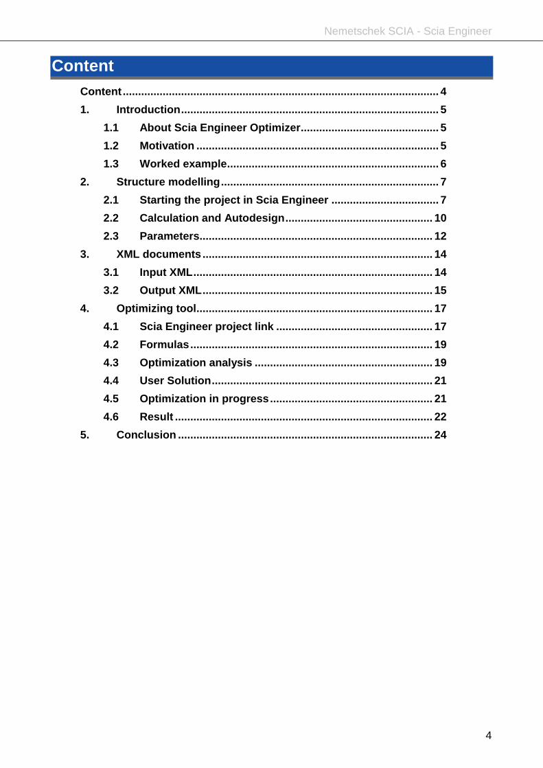
Scia Engineer Optimizer is an example of a new generation of software for the design of structures. It is software which calculates internal forces, checks the compliance to the code, and on top of that, this software is able to “find” the final optimal structural design.
It represents a combination of the widespread structural analysis software - Scia Engineer - and a separate optimization engine (EOT – Engineering Optimization Tool). The two programs have been integrated together and offer a versatile and complete optimization solution for all types of civil engineering structures.
1.2 Motivation
Scia Engineer Optimizer is very general and flexible because the demands which need to be considered during a really optimal structural design are also rather complex and general. However, thanks to the power of the current computational technologies, all requirements for cost reduction, material savings and environmental protection can be now easily met. Despite the complexity of the general optimization, the optimization process itself is not complicated and this manual will lead you how to proceed.

Nemetschek SCIA - Scia Engineer
6
Once all the required input data are entered, i.e. the model of the analysed structure is defined, the search for the optimal solution runs fully automatically and no interaction from the user is required. For real-life problems several optimal solutions can be found. In such situations, it is up to the user to make the final decision.
Depending on our requirements we may seek different targets. The goal of the optimization depends on us: is it the total weight, costs, eigen frequency or something else. And with respect to the goal, there are many possibilities of what can be optimized, what means, which properties or parameters of the structure are to be changed to reach the optimum: geometry, cross-sections, reinforcement, prestressing, structural arrangement and others.
As the constraints we use various values obtained from Scia Engineer analysis: unity check, capacity, eigen frequency, deflection etc.
1.3 Worked example
This example shows the optimization of the geometrical shape with the aim to reach the minimum mass of a steel truss girder with respect to fulfilling the capacity according to for 1st limit state code check implemented in SCIA Engineer (EC3 in this case).
The structure is a simply supported truss girder with the span of 10 metres, see the next picture. The goal of optimization is find optimal height of the truss (which will most probably vary along the girder length, see results at the end of this tutorial).
All members have tubular cross-sections but the thickness and diameter are variable. However both values have to be within certain limitations.

Nemetschek SCIA - Scia Engineer
7
2. Structure modelling
2.1 Starting the project in Scia Engineer
First of all the standard Scia Engineer project must be prepared. Therefore, create a model of a structure with all the necessary aspects of the future optimization taken into account.
Run Scia Engineer and create a new project of the Analysis type.
The basic Project data can be filled in according to the picture below:

Nemetschek SCIA - Scia Engineer
8
Although the structure is planar, the structure type is set to General XYZ to keep it more general. The project level is set to Advanced, which is a generally recommended setting. The code of this particular project is set to EC-EN with the standard EN annex.
Press OK to confirm the settings and to open a blank project.
Model the truss girder with 1D members. First, you will be asked to select cross-sections for the current project. Add two tubular cross-sections with the dimensions:
CS1: D = 70 mm; t = 10 mm
CS2: D = 50 mm, t = 8 mm
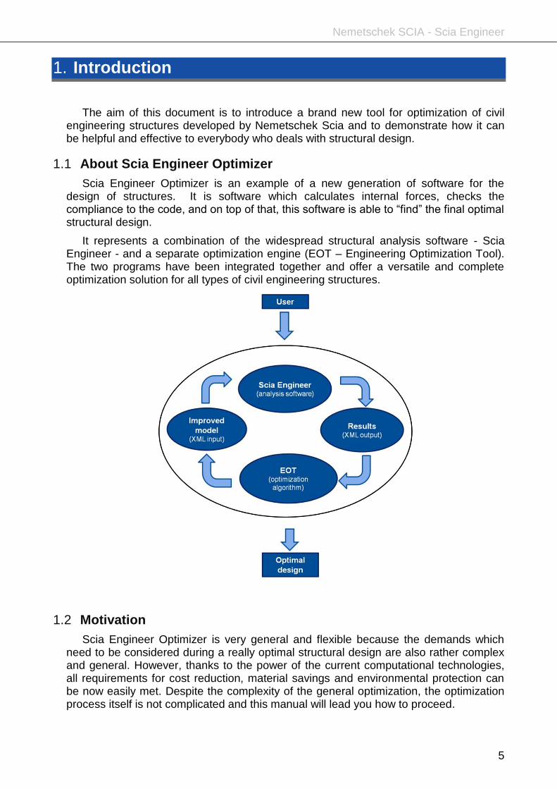
Create the structure according to the following scheme and table:
Nemetschek SCIA - Scia Engineer
9
The truss as a whole structure is simply supported. To restrain the lateral displacements, supports in all nodes must be defined to prevent from the deformation in the Y direction.
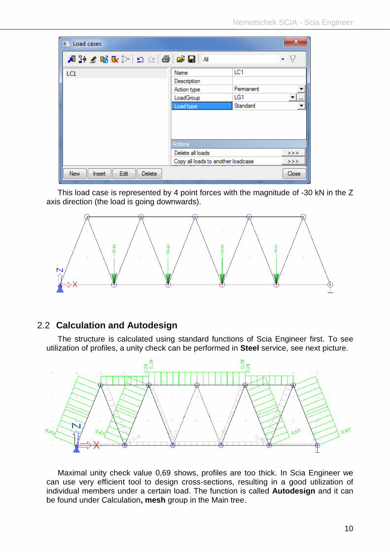
When the structure is modelled, loads have to be specified as well. The truss girder is subjected to a simple load case with vertical point forces in the bottom nodes. Create a new load case with the action type Permanent and load type Standard.
Nemetschek SCIA - Scia Engineer
10
This load case is represented by 4 point forces with the magnitude of -30 kN in the Z axis direction (the load is going downwards).
2.2 Calculation and Autodesign
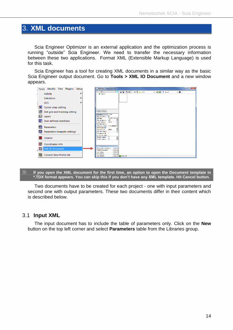
The structure is calculated using standard functions of Scia Engineer first. To see utilization of profiles, a unity check can be performed in Steel service, see next picture.
Maximal unity check value 0,69 shows, profiles are too thick. In Scia Engineer we can use very efficient tool to design cross-sections, resulting in a good utilization of individual members under a certain load. The function is called Autodesign and it can be found under Calculation, mesh group in the Main tree.

Nemetschek SCIA - Scia Engineer
11
Autodesign can be used for various purposes. The Cross-section steel check will be used in this case. This Autodesign function finds an optimal cross-section with respect to the unity check for all members with this cross-section. However, as the change of a profile in a statically indeterminate structure affects the internal forces, the project has to be recalculated. For new internal foces, after recalculation, we can run Autodesign again. The user can do those two steps several times to reach proper cross-section design.
Autodesign is also integrated in optimization loop s of EOT. It means, during iterative search of optimal structure geometry, the program will make design of proper cross-sections. It means, in each iterative step, both geometry and cross-sections will be improved at the same time.
Prepare a new entry (called O1) in the Overall Autodesign library. Select both cross-sections (CS1 and CS2) in the selection dialogue. It means that the items count will be 2.
Each cross-section has got two dimensions in their properties – thickness t and diameter D. Both dimensions can be changed upwards and downwards in order to search for the optimum. To optimise both variables in one run, we will keep a fixed ratio between D and t. Advanced Autodesign is used for this.

Nemetschek SCIA - Scia Engineer
12
It is not needed to do the Autodesign at this moment. EOT application will use this stored setting afterwards.
2.3 Parameters
The optimization is based on parameters. Scia Engineer allows the user to prepare lot of different kinds of parameters, which can be assigned to various entities and/or properties.
In this particular example we want to adapt the shape of the upper chord to get the minimum mass of the structure. This means that some nodes will change their positions (z-coordinates). Therefore, we will to make a set of parameters and we will assign them to properties of nodes.
To make parameters available, we have to switch them on in functionality setting:

Nemetschek SCIA - Scia Engineer
13
Then, let us open parameters library under Tools > Parameters. New items can be added with the button New in the top left or the bottom left corner (both these buttons do the same).
Prepare three parameters which will specify the Z coordinate of nodes of the upper chord. As we need a symmetric structure three parameters will be sufficient. The type of parameters is set to Length, Evaluation to Value and the default value is 2.5 m at the moment.
Assigning parameter to a node is simple. Just select a node and then, assign the parameter to the value of this property of selected node.
Select the outside nodes N6 and N10 and change their Coord Z to z1.
Select the inner nodes N7 and N9 and change their Coord Z to z2.
Select the the middle node N8 and change its Coord Z to z3.
When the value of particular parameter is changed, the structure reacts immediately. However, let us assign this job to EOT. It shall calculate the correct value for each of the parameters.
Nemetschek SCIA - Scia Engineer
14
3. XML documents
Scia Engineer Optimizer is an external application and the optimization process is running “outside” Scia Engineer. We need to transfer the necessary information between these two applications. Format XML (Extensible Markup Language) is used for this task.
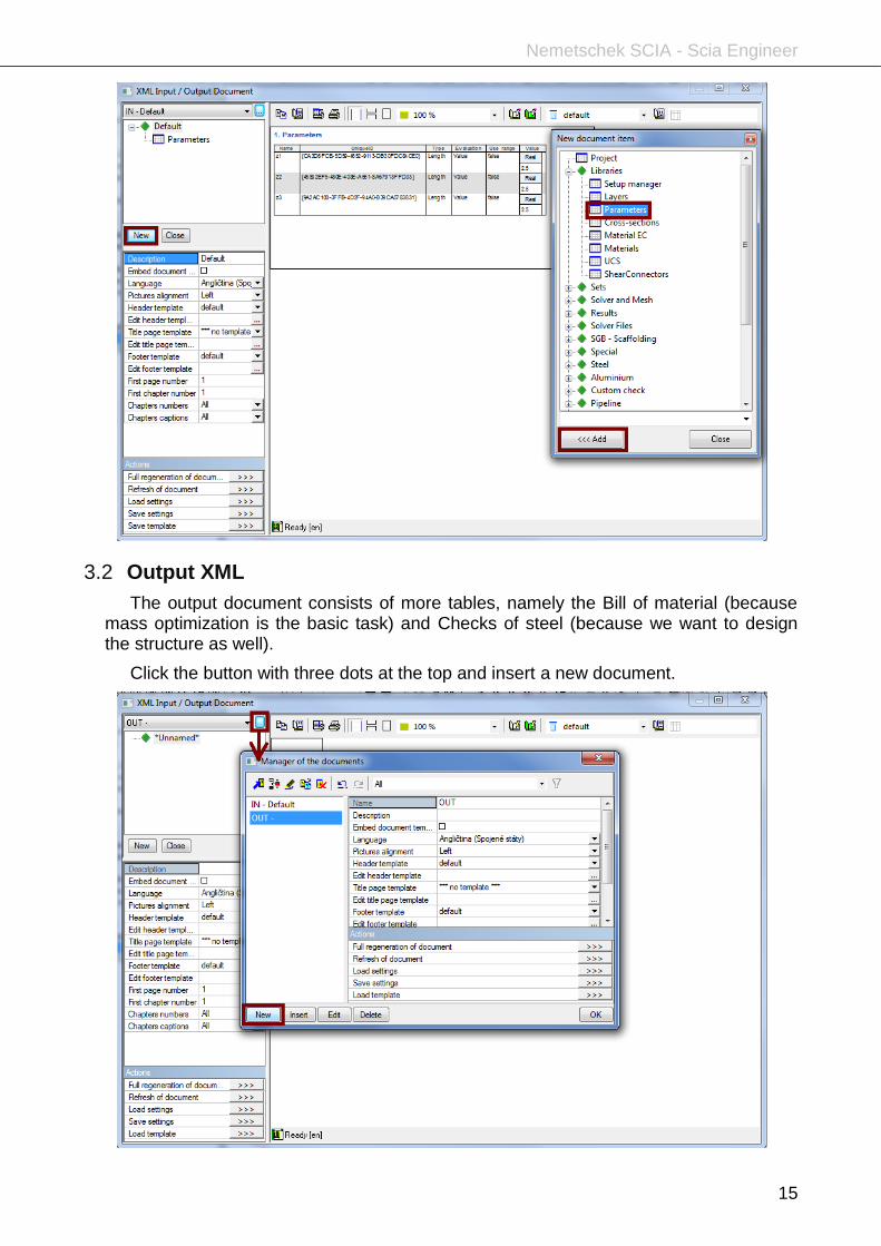
Scia Engineer has a tool for creating XML documents in a similar way as the basic Scia Engineer output document. Go to Tools > XML IO Document and a new window appears.
If you open the XML document for the first time, an option to open the Document template in *.TDX format appears. You can skip this if you don’t have any XML template. Hit Cancel button.
Two documents have to be created for each project - one with input parameters and second one with output parameters. These two documents differ in their content which is described below.
3.1 Input XML
The input document has to include the table of parameters only. Click on the New button on the top left corner and select Parameters table from the Libraries group.
Nemetschek SCIA - Scia Engineer
15
3.2 Output XML
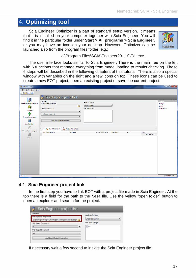
The output document consists of more tables, namely the Bill of material (because mass optimization is the basic task) and Checks of steel (because we want to design the structure as well).
Click the button with three dots at the top and insert a new document.

Nemetschek SCIA - Scia Engineer
16
Click on the New button in the top left corner and add the desired tables:
Bill of material from the Results group
Check of steel from the Steel group (this has to be input twice – for each cross-section)
Below you can see the settings for each table included in the document. Note that the check of steel is filtered by cross-section and the first and the second item differ in this setting only.
Refresh the document to see if all the data are correctly loaded and close the window by the red cross in the top right corner.
It is wise to type a name of both documents so that they could be better recognized later. “IN” and “OUT” is the simplest possibility and it works well.
Nemetschek SCIA - Scia Engineer
17
4. Optimizing tool
Scia Engineer Optimizer is a part of standard setup version. It means that it is installed on your computer together with Scia Engineer. You will find it in the particular folder under Start > All programs > Scia Engineer, or you may have an icon on your desktop. However, Optimizer can be launched also from the program files folder, e.g.:
c:\Program Files\SCIA\Engineer2011.0\Eot.exe.
The user interface looks similar to Scia Engineer. There is the main tree on the left with 6 functions that manage everything from model loading to results checking. These 6 steps will be described in the following chapters of this tutorial. There is also a special window with variables on the right and a few icons on top. These icons can be used to create a new EOT project, open an existing project or save the current project.
4.1 Scia Engineer project link
In the first step you have to link EOT with a project file made in Scia Engineer. At the top there is a field for the path to the *.esa file. Use the yellow “open folder” button to open an explorer and search for the project.
If necessary wait a few second to initiate the Scia Engineer project file.

Nemetschek SCIA - Scia Engineer
18
Once the project is loaded, the input and output documents are ready to be selected from the list of available XML documents. Usually, only the output document has to be switched as it is the second one from the offer.
Select the right input and output document and click the button below called Load Input/Output Parameters. Wait a few seconds again until all parameters are displayed in the table (and in the right panel as well).
At this point new files are automatically generated in the folder where the project is saved. The files are related to the input and output XML documents and two files are created for both of them *_in.xml *_out.xml *_in.xml.def *_out.xml.def
The middle part of the screen shows also the available types of Analysis Settings. Leave the default Linear Calculation option selected in the combo-box.
If any autodesign item has been created in the used Scia Engineer project it will be listed in the white box here. Tick the items you want to be included in the optimization procedure. We want to design all cross-sections in Scia Engineer, thus tick the O1 Autodesign.

Nemetschek SCIA - Scia Engineer
19
4.2 Formulas
The Scia Engineer Optimizer is a scientific tool where you don’t have to fully rely on what have been programmed but where you can add your own formulas. At the beginning of the text editor for formulas there is a paragraph with hints and instructions about how this environment can be used. There is also a list of supported functions.
However, the whole step is optional. We won’t be dealing with it in this tutorial.
4.3 Optimization analysis
In the third step the optimization analysis is set. Variables, constraints and objective are selected and the type of strategy is chosen.
All independent variables ticked in the input parameters are displayed in the first tab. Please, pay attention to their minimum and maximum values to keep the design inside reasonable boundaries. Any variable can be set as constant; basically it is the

Nemetschek SCIA - Scia Engineer
20
same as omitting it. We decided to remain the top level of the girder, thus z3 is constant.
The Optimization tab requires more settings - all related to the analysis itself:
Type of strategy
There are 5 strategies implemented in EOT. Each strategy has its own specifications and is suitable for different examples. Sometimes it is necessary to test more strategies, but the detailed discussion about the selection of the strategies is out of scope of this tutorial. For our example select the heuristic method called Nelder –Mead strategy.
Strategy settings
This button enables advanced users to adjust the properties of the selected strategy. Leave the defaults.
Objective
The intention of the whole optimization is specified here. There are two extremes that can be determined – maximum or minimum. Type a variable name from the list of dependent variables (see the right stripe of the window) into the white field.
Constraint
There may be some restrictions for the optimization. In our case we want to design the structure with respect to code regulations. The unity check of all members has to be lower than 1.0. There are two cross-sections and for both of them the section check and the stability check is considered. There are four constraints in total: the name is taken from the list of variables and the condition set is smaller or equal to 1.
The control in the bottom window tells us if all criteria are all right.
When ready, click button !! RUN !!

Nemetschek SCIA - Scia Engineer
21
4.4 User Solution
The user can use his own independent variables and calculate the objective and other dependant variables anytime before or after the optimization. Fill in the white fields in the table and click the Resolve button to run the calculation, if desired.
A typical advantage of this tool is when the results is for example 0,98 and you want to apply rounded values. In this case type 1,0 and resolve the structure with user solution.
4.5 Optimization in progress
During the optimization only the current step in the left menu is available. The iterations can be monitored in the main window under the Optimization report tab.
There is also a second tab with All solutions the number of which increases during the calculation.
The bottom status bar shows the progress, total time, average time per one solution and there are also two important buttons for pausing or stopping the optimization.
Nemetschek SCIA - Scia Engineer
22
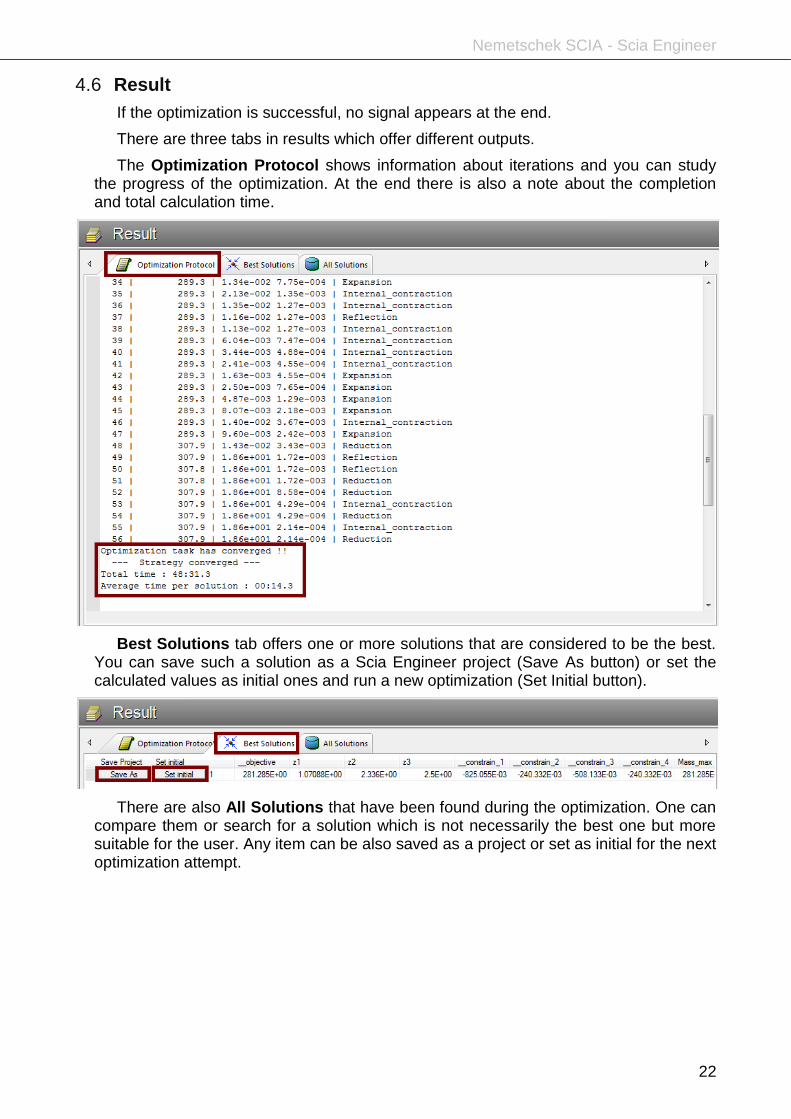
4.6 Result
If the optimization is successful, no signal appears at the end.
There are three tabs in results which offer different outputs.
The Optimization Protocol shows information about iterations and you can study the progress of the optimization. At the end there is also a note about the completion and total calculation time.
Best Solutions tab offers one or more solutions that are considered to be the best. You can save such a solution as a Scia Engineer project (Save As button) or set the calculated values as initial ones and run a new optimization (Set Initial button).
There are also All Solutions that have been found during the optimization. One can compare them or search for a solution which is not necessarily the best one but more suitable for the user. Any item can be also saved as a project or set as initial for the next optimization attempt.

Nemetschek SCIA - Scia Engineer
23
Three buttons in the bottom right corner enables the user to Save protocol (the same as you see on the screen, in *.txt format), Save tables as CVS or Export (results) to Excel. The last option opens Microsoft Excel with a new file containing three tabs – exactly the same as in Results of the EOT application. The advantage of such an export is that you can insert illustrative graphs to demonstrate the optimization process.
This result shows quite remarkable material savings, as the original mas 524 kg was finally reduced to 281,2 kg, only by means of optimization of geometry of the structure!

Nemetschek SCIA - Scia Engineer
24
5. Conclusion
If you save the selected result using button “Save As” (see picture above) and open the saved .esa file, you will get the corresponding structure (see also attached file Steel truss girder_best.esa).
Important note:
The structure saved this way contains the status corresponding to the values of parameters. To get also correct cross-sections, it is necessary to run Autodesign function manually!
Run linear analysis and Autodesign afterwards in Scia Enigneer. Use the Optimization Routine for iterative design (due to reasons described in chapter 2.2). Let the software determine automatically how many iterations are necessary and click the button Start.
Nemetschek SCIA - Scia Engineer
25
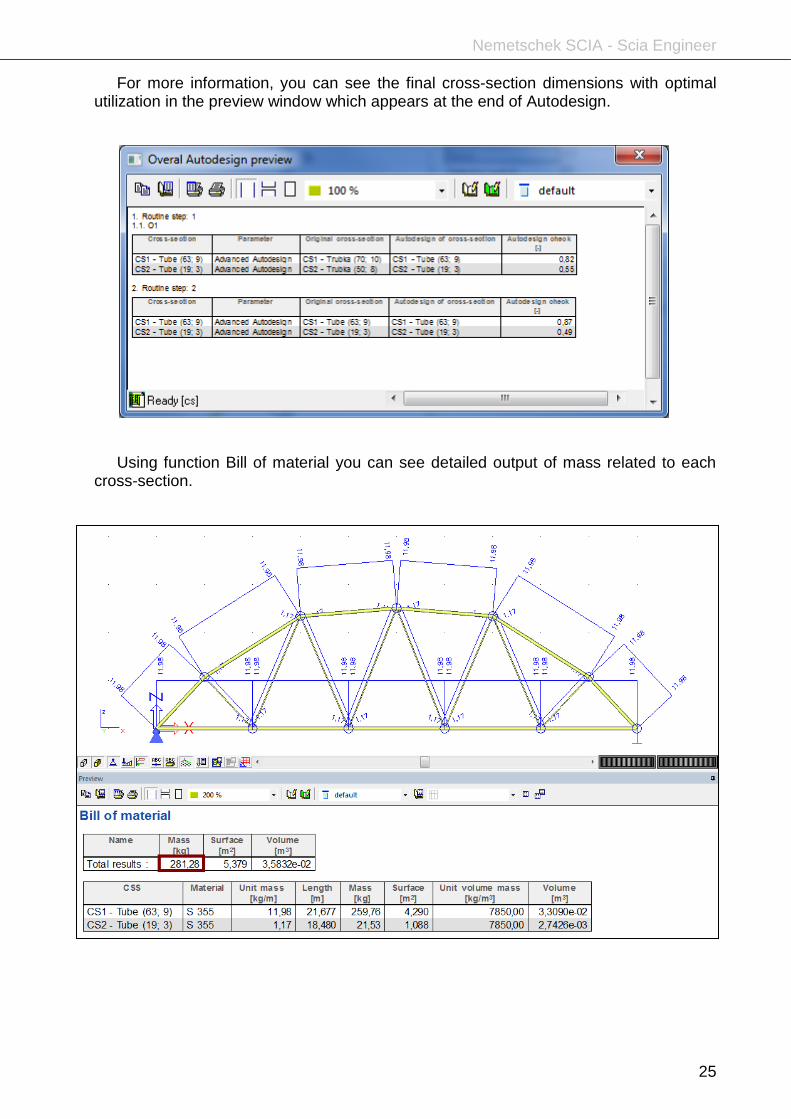
For more information, you can see the final cross-section dimensions with optimal utilization in the preview window which appears at the end of Autodesign.
Using function Bill of material you can see detailed output of mass related to each cross-section.


![[Eng]Tutorial Plate Concrete 18.0 - SCIA Structural …...1 General Information Welcome Welcome to the SCIA Engineer Tutorial Frame Concrete. SCIA Engineer is an integrated, multi-material](https://img.pdfslide.net/doc/110x75/5e52d3db58e6d209f2727a8a/engtutorial-plate-concrete-180-scia-structural-1-general-information-welcome.jpg)