Embed Size (px)
Citation preview

SCIENCE MISSION OPERATIONS AND EARLY SCIENCE INTRUMENTS FOR SOFIA
Helen J. Hall¹, Erick T. Young¹, Hans Zinnecker²,³
¹SOFIA Science Center, Universities Space Research Association, NASA Ames Research Center
MS 232, Moffett Field, CA 94035, USA
²SOFIA Science Center, NASA Ames Research Center, MS 211-1, Moffett Field, CA 94035, USA
³Deutsches SOFIA Institut, Universität Stuttgart, Pfaffenwaldring 29, D-70569 Stuttgart,
Germany
ABSTRACT
SOFIA, the Stratospheric Observatory for Infrared Astronomy, is a joint project between NASA and DLR to provide
a 2.5-m telescope that flies at stratospheric altitudes. Access to large parts of the otherwise blocked infrared
spectrum is enabled. SOFIA successfully conducted its first year of science observations in 2011. The instruments
that were flown in the demonstrating “Early Science” phase were the FORCAST mid-infrared camera, the GREAT
heterodyne spectrometer, and the HIPO photometer. The FLITECAM near- infrared imager was briefly flown
married with HIPO. The remainder first generation Science Instruments to be flown is the HAWC far infrared
bolometer camera, the FIFI-LS far infrared field imaging line spectrometer, and EXES, a high resolution echelon
spectrometer. In this paper we present the basic characteristics of the airborne observatory and the management of
the Science Mission Operations.
Key words: infrared: Science Mission Operations, science instruments
1. INTRODUCTION
The Stratospheric Observatory For Infrared Astronomy (SOFIA) is a joint project of the National Aeronautics and
Space Administration, USA (NASA) and the German Aerospace Center Deutsches Zentrum für Luft und-Raumfahrt
(DLR). SOFIA consists of a German-built 2.5-meter telescope mounted in a modified Boeing 747-SP aircraft
supplied by NASA. Operations costs and observing time is shared by the United States (80%) and Germany (20%).
Flying at altitudes up to 45,000-feet, SOFIA observes from above more than 99 percent of Earth’s atmosphere water
vapor, thereby opening windows to the universe not available from ground-based telescopes. SOFIA will observe at
wavelengths from 0.3µm to 1.6mm. When SOFIA reaches full operations approximately 1000 high-altitude
observing hours will be offered to the science community per year and will operate for 20 years. [1] Four of the
seven first generation science instruments have flown during early science including imaging cameras and a
heterodyne spectrometer. Other benefits of SOFIA are training young scientists in instrument development and
flying educators. Journalists have also flown on SOFIA making it a valuable platform and public ambassador. The
Universities Space Research Association (USRA) and the Deutsches SOFIA Institute (DSI) from the University of
Stuttgart are the science mission contractors. Science flights originate from the NASA Dryden Flight Research
Center (DFRC) in southern California and the science center is located at the NASA Ames Research Center (ARC)
near San Francisco.

Figure 1 A cutaway view of the SOFIA Observatory
The telescope is mounted in an open cavity in the aft section of the aircraft “Figure 1” and views the sky through a
port-side doorway. The door has a rigid upper segment and a flexible lower segment that can be tracked together to
allow the telescope to operate, unvignetted, over an elevation range of 23° - 58°. The telescope is moved by
magnetic torquers around a 1.2m diameter spherical hydrostatic bearing that floats under an oil pressure of 20
atmospheres within two closely fitting spherical rings. The rings are mounted in the 6.4m diameter pressure
bulkhead on the axis of the Nasmyth beam. The travel of the bearing for azimuth tracking is only ±3° so the aircraft
must be steered to provide most of the azimuthal telescope movement required for tracking. Hence, the list of
targets to be observed determines the flight plan. The forward part of the airplane is pressurized, and the working
environment for the crew is typical of that in a commercial airliner. This pressurized region provides access to the
science instrument(s) during the flight. [2]
Figure 2 Schematic of the optical system of the SOFIA telescope.

Everything left of the bulkhead is contained in the forward pressurized crew cabin, while everything to the right
is contained in the open telescope cavity.
2. SCIENCE MISSION OPERATIONS ORGANIZATION
The physical elements of the SOFIA Observatory include the Airborne Observatory and two ground-based
components: the SOFIA Science Center at ARC (Moffett Field) and the NASA Dryden Aircraft Observatory
Facility (DAOF) in Palmdale, California. The SOFIA Telescope Assembly (TA), the modified aircraft with its
Mission Controls and Communications System (MCCS), environmental control systems, and any Science
Instruments (SI) installed onboard the aircraft together comprise the Airborne Observatory. The Airborne System
Operations element provided by DFRC operates the aircraft, maintains the supporting systems according to
requirements established by the Science Mission Operations (SMO) organization, and have airworthiness authority
for the SIs. The SMO will direct the science activities of the observatory, including selecting and prioritizing
science proposals, planning science missions and providing the science data archive for community utilization. [3]
The Science and Mission Operations (SMO) organization is made up of staffing from USRA and the DSI. The
SMO element has split Geographic locations. The components of the SMO located at the SOFI Science Center at
ARC include the SMO Director (USRA) and SMO Deputy Director (DSI), science staff, science data network,
Mission Planning staff, Systems Integration Laboratory, Science Instrument (SI) Laboratories, and the Education
and Public Outreach. Jointly sponsored PhD interns from the University of Stuttgart are also located at ARC. The
SMO components operated at the DAOF include the Telescope Assembly (TA), SI Integration Team, Operations
staff that fly on the missions, SI Laboratories, Systems Integration Laboratories, the Mirror Coating Facility (MCF),
and Mission Systems Flight Data retrieval and Observatory Data Cache.
Fig.3 Data Cycle System Tools for Annual Lifecycle
The planning process for the Annual Operating Plan starts with the Call for Proposals (CfP). The scientific
community utilizes the SOFIA Science Center web-based tools to prepare their proposals. The SOFIA Proposal
Tool (SPT) is based on the Astronomer’s Proposal Tool (APT) developed for the Hubble Space Telescope proposal
process. The SOFIA Instrument Time Estimator (SITE) calculates exposure times for the specific SIs. There are
also links to an Observer’s Handbook to ensure the astronomical community have technically adequate proposals.
The Atmospheric Transmission Estimator (ATRAN) is used specifically for the GREAT heterodyne spectrometer
since an observer has to know the atmospheric transmission as a function of wavelength. The Target Visibility
Tool is used to detail the permissible target elevations and flight times. Once the technical reviews have been
completed, and the Time Allocation Committee (TAC) has been held, the SMO Director performs the selection of
the planned observations taking into account the advice of the TAC. The detail flight planning then is conducted.
Guest investigators are encouraged to fly, if there is room. The experience of flying is unique. The SMO staff
conducts the missions and process the data products for the guest investigators and the data archive.
Fig.4 a & b, Left – Photo of the mid-Infrared Camera FORCAST mounted on the Telescope Assembly. One can
see the backs of the Science Instrument team collecting the data in flight. Right – Photo of the Aluminized
Primary Mirror Assembly peering out into the night during Line Operations.
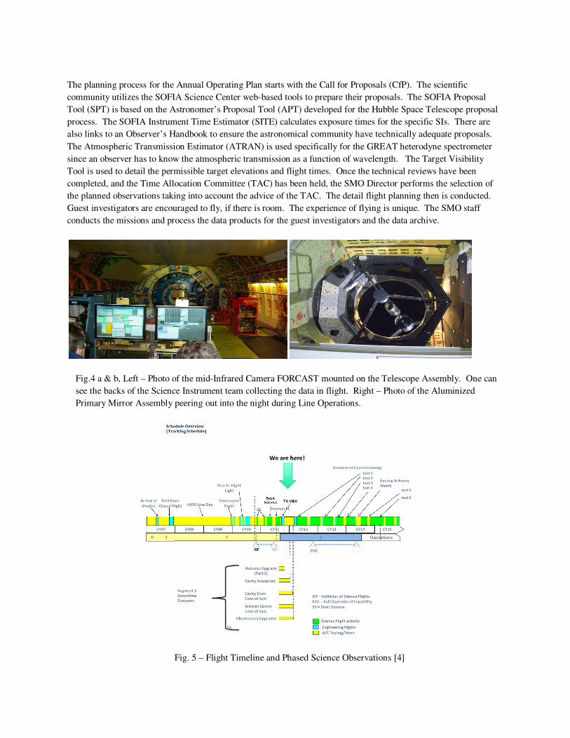
Fig. 5 – Flight Timeline and Phased Science Observations [4]

Line Operations is when we pull the plane out of the hanger, treat SOFIA like a ground-based observatory, point the
telescope at a target, and exercise the systems integration with the science instruments.
The project completed the Initiation of Science Flights, Short Science (6 flights), and Basic Science (22 Flights)
with the mid-Infrared camera FORCAST and the GREAT heterodyne spectrometer. This was followed by
additional Telescope Assembly (TA) Verification & Validation flights with the HIPO photometer (9 flights). There
will be another paper at this conference showing the science results of Early Science by Jim DeBuizer. A short
Segment 3 Downtime starting the beginning of calendar 2012 has been done to prepare Avionics Upgrades for the
modified 747-SP, more cavity insulation and pre-cooling enhancements for the TA, and Mission Communication
and Control System (MCCS) upgrades to optimize the software based on lessons learned from Early Science.
3. SCIENCE INSTRUMENTS
The SMO’s responsibility is to develop the first generation of SOFIA instruments on the US side and integrate all of
the instruments onto the observatory.
Fig. 6 – Geographic Distribution of first generation SOFIA Instruments and the entities that are building them
Seven Science Instruments (SI)s are under development for SOFIA. They cover a wide range of wavelengths and
spectral resolution. These include four Facility Class Science Instruments (FSI)s: the Faint Object InfraRed Camera
for the SOFIA Telescope (FORCAST), the First Light Infrared Test Experiment CAMera (FLITECAM), the Field
Imaging Far-Infrared Line Spectrometer (FIFI-LS), and the High-resolution Airborne Wideband Camera (HAWC).
The FSIs will be maintained and operated by the SMO staff. In addition, there are three Principal Investigator (PI)
class instruments maintained and operated by the PI teams: the German Receiver for Astronomy at Terahertz
Frequencies (GREAT), High-speed Imaging Photometer for Occultation (HIPO), and the Echelon-Cross-Echelle
Spectrograph (EXES). These instruments are designed to be less general in their potential applications than are the
FSIs and are more likely to undergo upgrades between flight series, which has the advantage of keeping them more
state-of-the-art at the expense of not having fixed capabilities. General investigators can propose to use these latter
instruments in collaboration with the PI team that developed the instrument. All SIs will have pipeline-reduced and
flux calibrated data that will be archived for general access by the astronomical community after a one year
exclusive access (proprietary) period. [1]

3.1 FORCAST
FORCAST is a facility class, mid-IR diffraction-limited camera with selectable filters for continuum imaging in two
bands (5-25 µm and 25-40µm). For the Early Science, the bands available were 5.4, 6.4, 6.6, 6.7, 7.7, 8.6, 11.1,
11.3, 19.7, 24.2 µm for the Short Wavelength Camera and 31.5, 33.6, 34.8, 37.1 µm for the Long Wavelength
Camera. FORCAST has also developed low resolution (R=200-800) grism spectroscopy in the 4-8, 16, 25 and/or
25-40µm regions. FORCAST will provide the highest spatial resolution possible with SOFIA at wavelengths longer
than ~5µm. Simultaneous high-sensitivity wide-field imaging can be performed in the two-channels using 256 x
256 Si:As and Si:Sb detector arrays which sample at 0.75 arcsec/pixel giving a 3.2 arcmin x 3.2 arcmin field-of-
view. FORCAST can be used in a single channel mode or in a dual channel mode that uses a dichroic to split the
incident light towards the short and long wavelength arrays, allowing one of the 11.1, 11.3, 19.7, or 24.2 µm short
wavelength filters to be used simultaneously with any of the long wavelength filters. Alternatively, any filter can be
used in the single channel mode to maximize sensitivity. For small objects (less than half the size of the array in the
horizontal or diagonal directions), chopping and nodding can be performed on the array to increase sensitivity and
shorten the overhead time associated with beam switching. [5]
3.2 GREAT
GREAT, a PI-class instrument, is a 2-channel heterodyne instrument that offers observations in three frequency
bands with frequency resolution down to 45 kHz (R ~ 4x10⁷). The lower band, 1.4 – 1.9 THz, covers fine-structure
lines of ionized nitrogen [NII] and ionized carbon [CII]. The middle band is centered on the cosmology relevant 1-0
transition of deuterated molecular hydrogen (HD) at 2.7 THz and the rotational ground-state transition of OH at 2.5
THz. A high-frequency band includes the 63 µm transition of [OI]. The receivers employ sensitive
superconducting mixer elements, superconductor-insulator-superconductor (SIS) tunnel junctions and hot electron
bolometers. A polarizing beam splitter allows simultaneous measurements of two channels at the same time. [1]
For Early Science, the supported observing modes for GREAT were Position switching, Beam switching and On-
the-fly mapping. The receiver bands L#1 and L#2 are operated simultaneously. Both have instantaneous
bandwidths ~1.2 GHz. Different frequencies can be set in each band. Both back ends (two for each band) record
data simultaneously. The frequency ranges of the two receiver bands are L#1 = 1.25 – 1.5 THz (200 – 240 µm) and
L#2 = 1.82 – 1.92 THz (156 – 158 µm). Two array Acousto-Optical Spectrometers (AOS) with 1 MHz (R~ 106)
and two Chirp-Transform-Spectrometer (CTS) spectrometers: 220 MHz bandwidth and 47 kHz resolution were used
as back ends. [5]
3.3 HIPO
HIPO is a special-purpose instrument designed to provide simultaneous high-speed, time-resolved imaging
photometry at two optical wavelengths. Its primary science objective is observation of stellar occultations by solar
system objects, the main targets being Pluto, Charon, Triton, and the larger and brighter Kuiper Belt Objects
(KBOs). Scientific issues to be addressed include surface/atmosphere interactions, presence of atmospheres on
small bodies, and in the case of KBOs the diameter and albedo of the objects. Additional science objectives fall in the category of precise photometry – transit light curves of extra-solar planets and stellar oscillations.
The nature of these observations is such that accurate time and position data are required to support the time-
resolved photometric data. These properties make HIPO well-suited to the task of initial testing of the SOFIA
observatory, and it will be heavily involved in this area as well. Several special features have been added to HIPO
to support this task. [6]

HIPO and FLITECAM can be mounted simultaneously to enable data acquisition at two optical and one near-IR
wavelengths. The primary HIPO detectors are e2v CCD47-20 1024 x 1024 pixel frame transfer CCDs with plate
scales of 0.33" x 0.33" pixels at low resolution and 0.05" x 0.05" pixels at high resolution. The HIPO field of view
(FOV) is a 5.6' square, the 8' diagonal of which corresponds to the 8' diameter SOFIA FOV. Pixels will normally be
binned to best match the seeing blur size and to reduce the effect of read noise.
3.4 FLITECAM
FLITECAM is a near-infrared (1 – 5 µm) camera and spectrometer for SOFIA. FLITECAM has a circular field of
view of 8’ diameter inscribed within a 1024 x 1024 InSb Aladdin III detector. There are two primary observing
modes, direct imaging and grism spectroscopy using fixed slits. In addition, there is a special rapid-exposure
“movie” mode for occultation studies, as well as a pupil-viewing mode intended primarily for observations near 3.0
– 3.5 microns. By designing FLITECAM to operate in a vertical orientation at the Cassegrain focus of the Lick
Observatory Shane telescope (3.0 m f/17) as well as in the horizontal orientation at the Nasmyth focus of SOFIA
(2.5 m, f/19.7), the instrument could be tested and evaluated independently of the SOFIA platform, except for the
very longest wavelengths where ground-based backgrounds are too high. [7]
3.5 FIFI-LS
FIFI-LS is an imaging spectrograph, comprised of two medium resolution (R-2200) grating spectrometers that feed
two 16 x 25 pixel detector arrays, enabling simultaneous line observations within two wavelength ranges (42 – 110
µm and 110-210 µm). An image slicer provides spatial information, redistributing the field-of-view along 25
entrance slits. FIFI-LS will offer instantaneous coverage at 50 km/s – 240 km/s resolution over a velocity range of
1500-3000 km/s around selected lines for each of the 25 spatial pixels. [8]
3.6 HAWC
HAWC is a far-infrared camera designed to cover the 40-300 µm spectral range at diffraction-limited resolution.
HAWC utilizes a 12 x 32 pixel array of bolometer detectors constructed using the silicon pop-up detector (SPUD)
technology developed at Goddard Space Flight Center. The array will be cooled by an adiabatic demagnetization
refrigerator and operated at a temperature of 0.2 K. HAWC will be upgraded to perform far infrared polarimetry
during the 2nd general science instruments process. [1]
3.7 EXES
The Echelon-Cross-Echelle Spectrograph (EXES) operated in three spectroscopic modes (R~105, 104, 3000) from 5
– 28 µm using a 1024 x 1024 Si:As blocked impurity band (BIB) detector. High dispersion is provided by a large
echelon grating. This required an echelle grating to cross-disperse the spectrum, resulting in continuous wavelength
coverage of ~5 cm-1 and a slit length of ~ 10” at R=105. The echelon can be bypassed so that either the echelle or
low order spectrum with slit length of roughly 90” and R=104 or 3000, respectively. The low resolution grating also
serves as a slit positioning camera when used face on. [1]
4.0 Education and Public Outreach (E/PO)
The overarching goals of SOFIA E/PO are to enhance Science, Technology, Engineering or Math ( STEM)
education in communities across the U.S., support NASA's goal of inspiring the next generation of explorers, and
contribute to general public understanding of the value of scientific research. SOFIA E/PO's flagship program, the
Airborne Astronomy Ambassadors (AAA), will train educators to work onboard SOFIA during research flights as
partners with astronomers. During FY 2011, the mission and its E/PO programs were in pilot/developmental phases,
ramping up toward full operations expected in 2014 and after. [9] In FY2011 6 US educators flew on Basic Science
flights, and a parallel German AAA program flew 2 educators during Basic Science 2.

1. The Science Vision for the Stratospheric Observatory For Infrared Astronomy, NASA Ames Research
Center, Moffett Field, CA, June 2009
2. Young E. et al, Early Science with SOFIA, The Stratospheric Observatory for Infrared Astronomy, ApJ
Letters, 749:L17 (5pp), 2012 April 20
3. Meyer, R. and Himmes, A., Stratospheric Observatory for Infrared Astronomy (SOFIA) NASA/DLR Joint
SOFIA Program Plan, Part II, Operations Phase, SOF-1005.2, January 2012
4. Zavala, E., Grunsfeld, J., Worden, P., McBride, D., Meyer, R., and Yoder, G., Program Plan Stratospheric
Observatory for Infrared Astronomy (SOFIA), SOF-DF-PLA-PM01-1000, December 2011
5. Gehrz, R. et al, Status of Stratospheric Observatory for Infrared Astronomy (SOFIA), Adv. Space Res., 48,
1004-1016, 2011
6. Casey, S., Savage, M., and Nelbach, F, HIPO Integration and Commissioning Plan, USRA-DAL-SSMOC-
HIPO-PLA-4000, February, 2007
7. McLean, I., et al, FLITECAM: current status and results from observatory verification flights, SPIE, draft,
2012
8. Krabbe, A., et al, FIFI-LS Science Case, January, 2011
9. Backman, D., et al, SOFIA Education and Public Outreach Program Management Plan, SOF-US-PLA-
PM09-2002, Rev. 5, September 2010