Embed Size (px)
Citation preview
Unit
rtn 5.6
Multipoint Conferencing
SCOPIA100 MCU Quick StaVersio
NOTICE
© 2000-2008 RADVISIONLtd. All intellectual property rights in this publication are owned by RADVISION Ltd and are protected by Italy and United States copyright laws, other applicable copyright laws and international treaty provisions. RADVISION Ltd retains all rights not expressly granted. This publication is RADVISION confidential. No part of this publication may be reproduced in any form whatsoever or used to make any derivative work without prior written approval by RADVISION Ltd. No representation of warranties for fitness for any purpose other than what is specifically mentioned in this guide is made either by RADVISION Ltd or its agents.
RADVISION Ltd reserves the right to revise this publication and make changes without obligation to notify any person of such revisions or changes. RADVISION Ltd may make improvements or changes in the product(s) and/or the program(s) described in this documentation at any time. If there is any software on removable media described in this publication, it is furnished under a license agreement included with the product as a separate document. If you are unable to locate a copy, please contact RADVISION Ltd and a copy will be provided to you. Unless otherwise indicated, RADVISION registered trademarks are registered in the United States and other territories. All registered trademarks recognized.
For further information contact RADVISION or your local distributor or reseller.
MCU version 5.6, June 2008Publication 11http://www.radvision.com
62787-00001 Rev A03
Quick Start
WHAT’S IN THIS GUIDE
This Quick Start provides the basic steps required for getting your SCOPIA100 MCU up and running. The suggested order of operation is as follows:
Preparing for Installation
1. Introduction2. Unpack and Verify the Equipment3. Prepare a Checklist4. Prepare the Site5. Mount the SCOPIA100 MCU Unit in a 19" Rack
(Optional)
Setting Up the MCU Component
6. Assign an IP Address to the MCU7. Connect to the IP Network8. Configure the MCU9. Save the Configuration
Setting Up the MVP Component
10. Assign an IP Address to the MVP11. Change the Configuration Software Password12. Point the MVP to the Controlling MCU13. Save MVP Network Configuration Settings
What’s in this Guide 1
Using the MCU
14. Create a Conference
Note For more detailed information, see the SCOPIA100 MCU User Guide
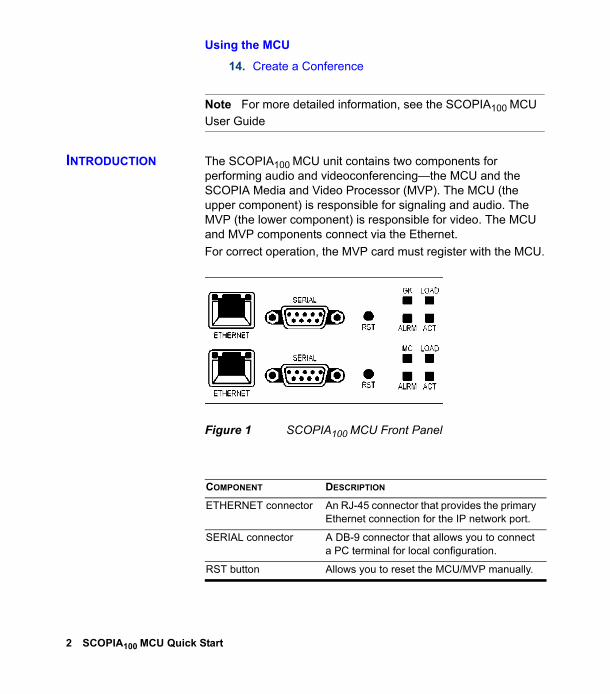
INTRODUCTION The SCOPIA100 MCU unit contains two components for performing audio and videoconferencing—the MCU and the SCOPIA Media and Video Processor (MVP). The MCU (the upper component) is responsible for signaling and audio. The MVP (the lower component) is responsible for video. The MCU and MVP components connect via the Ethernet.For correct operation, the MVP card must register with the MCU.
Figure 1 SCOPIA100 MCU Front Panel
COMPONENT DESCRIPTION
ETHERNET connector An RJ-45 connector that provides the primary Ethernet connection for the IP network port.
SERIAL connector A DB-9 connector that allows you to connect a PC terminal for local configuration.
RST button Allows you to reset the MCU/MVP manually.
2 SCOPIA100 MCU Quick Start
UNPACK AND VERIFY THE EQUIPMENT
The shipping box for a single SCOPIA100 MCU unit includes the following items:
SCOPIA100 MCU-12 or SCOPIA100 MCU-24 unitPower cable (depending on customer location)Terminal cable2 LAN cables (1 for the MCU, 1 for the MVP)Rack mounting kit (two brackets and three screws)Four rubber feetSCOPIA100 MCU User Guide (in PDF format only)SCOPIA100 MCU Quick StartSCOPIA MCU Release NotesUtilities and Documentation CD-ROM containing product documentation, utilities and online help files.
GK LED (on the SCOPIA MCU)MC LED (on the MVP)
Lights green when the MCU/MVP is registered with a gatekeeper, or when there is no gatekeeper registered and the auto attendant feature is enabled.
LOAD LED Lights green when more than 50% of MCU/MVP resources are in use.
ACT LED Lights green to indicate that there is at least one currently active conference on the MCU/MVP.
ALRM LED Lights green to indicate that an error has occurred and the MCU/MVP requires resetting.
ETHERNET LEDs The top part of the Ethernet connector contains two LED indicators. The left-hand LED lights green when the local IP network link is active. The right-hand LED lights green if the connection speed is 100 Mbps, and is off when the connection speed is 10 Mbps.
COMPONENT DESCRIPTION
Unpack and Verify the Equipment 3
PREPARE A CHECKLIST
Before you start configuration, fill in the checklist below:
For the MCU
IP address: _ _ _. _ _ _. _ _ _. _ _ _ IP subnet mask: _ _ _. _ _ _. _ _ _. _ _ _
Router IP address: _ _ _. _ _ _. _ _ _. _ _ _
Gatekeeper IP address: _ _ _. _ _ _. _ _ _. _ _ _
SIP Proxy IP address: _ _ _. _ _ _. _ _ _. _ _ _ (optional)
For the MVP
MVP IP address: _ _ _. _ _ _. _ _ _. _ _ _ MVP IP subnet mask: _ _ _. _ _ _. _ _ _. _ _ _
Router IP address: _ _ _. _ _ _. _ _ _. _ _ _
Note Typically, the MVP subnet mask and router IP address are the same as those used for the MCU.
PREPARE THE SITE
When installing the MCU, ensure that:Two IP ports are available on the switch—one for the MCU and one for the MVP.There is an available H.323 gatekeeper or SIP proxy server with which to register the MCU. (You may choose to work without an H.323 gatekeeper or SIP proxy server in the network. If so, ensure the auto-attendant feature is enabled.)
4 SCOPIA100 MCU Quick Start
MOUNT THE SCOPIA100 MCU UNIT IN A 19" RACK (OPTIONAL)
You can optionally mount the SCOPIA100 MCU unit in a standard 19-inch rack. Two mounting brackets and a set of screws are included in the SCOPIA100 MCU unit shipping box.
Procedure
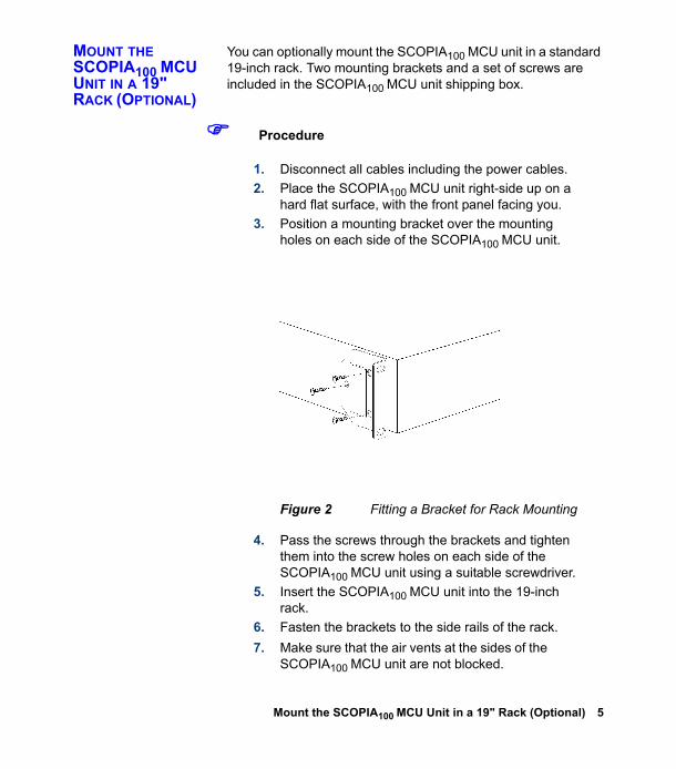
1. Disconnect all cables including the power cables.2. Place the SCOPIA100 MCU unit right-side up on a
hard flat surface, with the front panel facing you.3. Position a mounting bracket over the mounting
holes on each side of the SCOPIA100 MCU unit.
Figure 2 Fitting a Bracket for Rack Mounting
4. Pass the screws through the brackets and tighten them into the screw holes on each side of the SCOPIA100 MCU unit using a suitable screwdriver.
5. Insert the SCOPIA100 MCU unit into the 19-inch rack.
6. Fasten the brackets to the side rails of the rack.7. Make sure that the air vents at the sides of the
SCOPIA100 MCU unit are not blocked.
Mount the SCOPIA100 MCU Unit in a 19" Rack (Optional) 5
ASSIGN AN IP ADDRESS TO THE MCU
The first time you install the MCU, you assign an IP address using a terminal cable connection to access the boot configuration menu. At power-up, the MCU goes through the following boot phases:
Auto-boot—The embedded operating system initializes and displays basic information.Configuration menu—A six second countdown allows you to enter the configuration menu.Initialization—The MCU completes the boot sequence and is ready for operation.
Note You can perform serial port configuration of the MCU only at startup, during a short period indicated by a 6-second countdown. Once the initialization phase is complete, the only way you can access the configuration menu is by restarting the MCU.
CONNECT TO A PC You make the serial connection by connecting a PC terminal equipped with a terminal emulation application to the front panel serial port of the MCU.
Procedure
1. Connect the MCU COM port on the front panel to a PC terminal serial port using the supplied terminal cable.
2. Run a terminal emulation application (such as HyperTerminal) on the PC.
3. Configure the PC communication settings for the serial port as follows:
9600 Baud rate8 data bits1 stop bitNo parityNo flow control
6 SCOPIA100 MCU Quick Start
4. Start the terminal emulation application on the PC.5. Turn on or reset the MCU.
Note The debug mode prompt appears before the boot Configuration prompt. Ignore this message and wait for the boot Configuration prompt to appear.
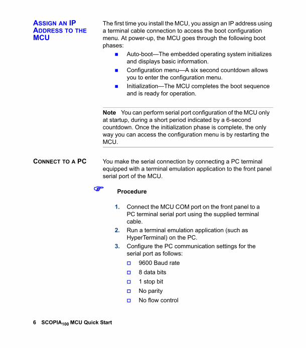
6. Press any key at the command prompt to display the network configuration Main menu.
Figure 3 Network Configuration Main Menu
Warning Configuration of any of the parameters other than <N> should not be performed by an unauthorized person.
Press any key to start configuration...Main menuN: Configure default network port valuesP: Change the configuration software passwordS: Configure network security levelA: Advanced configuration menuQ: Quit
Select:
Assign an IP Address to the MCU 7
CONFIGURE THE MCU IP ADDRESS
You set the IP address, default router IP address, and subnet mask as follows:
Procedure
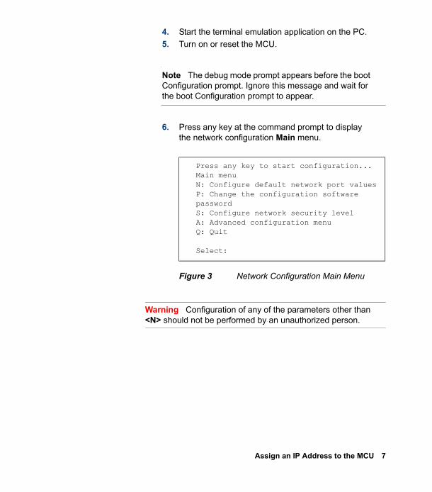
1. At the colon, type N to configure default network port values and press Enter.The default network port value configuration options display (Figure 4).
Figure 4 Configuring Default Network Port Values
2. Type the IP address, default router IP address, and IP subnet mask, pressing Enter to proceed from one parameter to the next.
3. Press Q to finalize the new settings and return to the main menu. The MCU automatically resets itself.
Enter values for default network portEnter IP Address for default InterfaceWithout leading zeros<172.20.27.105>:
Enter Default Router IP Address for default InterfaceWithout leading zeros<172.20.254.254>:
Enter IP Mask for default InterfaceWithout leading zeros<255.255.0.0>:
8 SCOPIA100 MCU Quick Start
CONNECT TO THE IP NETWORK
Use the supplied LAN cable to connect the Ethernet IP network port on the front panel of the MCU to a 100Base-T IP network connection on your network switch.
CONFIGURE THE MCU
Once you have assigned an IP address to the MCU, you can use the web interface to configure the MCU using the Setup Wizard.
Procedure
1. In your web browser, type the IP address of the MCU. For example: http://123.221.23.44Press Enter to display the Login screen.
2. Click the Sign In button to display the Name and Password fields.
3. Type the administrator user name and password in the Name and Password fields and click Go.
Note The default name is admin and the password is null. It is recommended that you change these settings for security reasons. For more information, see Change the Default Administrator Password on page 11.
4. The configuration interface displays and automatically launches the Setup Wizard.
RUN THE SETUP WIZARD
The MCU Setup Wizard allows you to configure addressing for the MCU IP, H.323 gatekeeper and SIP proxy and enables you to set the MCU to the regional date and time settings of the device on which you are managing the MCU. The Setup Wizard runs automatically the first time you access the MCU and can be accessed anytime subsequently by selecting the Setup Wizard button in the horizontal toolbar of the Device interface.
Connect to the IP Network 9
Procedure
1. When the Setup Wizard greeting page launches, click Next.The Board Settings window displays.
2. Type the MCU IP address, subnet mask and Router IP address, if necessary, and click Next.The H.323 Settings window displays.
3. Type the H.323 IP address and port number of the network gatekeeper on which H.323 calls to the MCU are routed and click Next.The SIP Settings window displays.
4. Type the SIP proxy IP, port and default domain address through which SIP calls to the MCU are routed.
5. If the SIP proxy server is a Microsoft Real-Time Communications Server (RTC), select Microsoft RTC and click Next.The Date and Time Settings window displays.
6. Set the system time of the MCU board to the local time of the PC on which you are managing the MCU.
10 SCOPIA100 MCU Quick Start
CHANGE THE DEFAULT ADMINISTRATOR PASSWORD
The default password of the MCU is set to null. It is recommended that you change the default administrator password.
Procedure
1. In the sidebar, click the Device button to display the Device configuration tabs.
2. In the Users tab select the Administrator user profile and click Edit.The Edit User dialog box displays where you can reset the administrator password.The new password is valid the next time you sign in to the MCU after signing out from the current session.
CHECK MCU SERVICE PREFIXES
The MCU includes pre-configured default service prefixes which are combined with a unique number to create the conference ID which you dial to join or create a conference. The default settings are listed in the Services tab of the MCU interface. You can modify the existing prefixes to suit your network dialing plan or define new services and add them to the list. You must ensure that the service prefix numbers are not identical to the first digits of any of your network endpoint phone numbers or aliases.
Procedure
1. In the MCU Services tab, click Add to add a new service, or select a service and click Edit to modify that service.
2. Type the prefix number for this service and set or modify additional settings as required and click OK.After confirming your settings, the MCU is automatically updated with the new service profile settings.
Configure the MCU 11
SAVE THE CONFIGURATION
The Export button on the toolbar allows you to save the MCU configuration parameters as a file to your local hard disk or a network directory.
Procedure
1. In the toolbar, click Export.The Windows File Download dialog is displayed.
2. Check the Save this file to disk option in the Windows File Download dialog and click OK.The Windows Save As dialog is displayed.
3. In the File name text box, type a filename, for example MCU1_NEW and select a location to save this configuration setup.
4. Click Save.
ASSIGN AN IP ADDRESS TO THE MVP
The first time you install the MVP, you assign an IP address using a terminal cable connection to access the boot configuration menu. At power-up, the MVP goes through the following boot phases:
Auto-boot—The embedded operating system initializes and displays basic information.Configuration menu—A six second countdown allows you to enter the configuration menu.Initialization—The MVP completes the boot sequence and is ready for operation.
Note You can perform serial port configuration of the MVP only at startup, during a short period indicated by a 6-second countdown. Once the initialization phase is complete, the only way you can access the configuration menu is by restarting the MVP.
12 SCOPIA100 MCU Quick Start
CONNECT TO A PC You make the serial connection by connecting a PC terminal equipped with a terminal emulation application to the front panel serial port of the MVP.
Procedure
1. Connect the MVP COM port on the front panel to a PC terminal serial port using the supplied terminal cable.
2. Run a terminal emulation application (such as HyperTerminal) on the PC.
3. Configure the PC communication settings for the serial port as follows:
9600 Baud rate8 data bits1 stop bitNo parityNo flow control
4. Start the terminal emulation application on the PC.5. Turn on or reset the MVP.
Note The debug mode prompt appears before the boot Configuration prompt. Ignore this message and wait for the boot Configuration prompt to appear.
6. Press any key at the command prompt to display the network configuration Main menu.
Assign an IP Address to the MVP 13
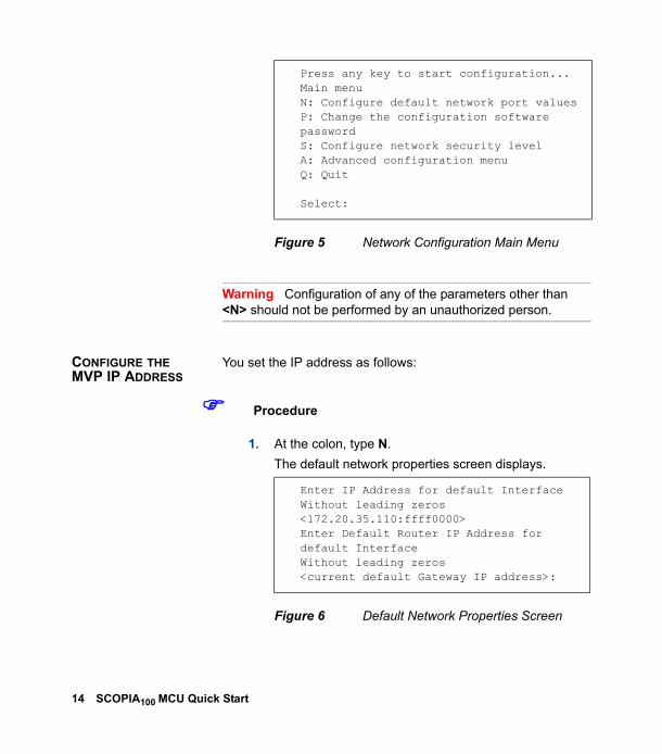
Figure 5 Network Configuration Main Menu
Warning Configuration of any of the parameters other than <N> should not be performed by an unauthorized person.
CONFIGURE THE MVP IP ADDRESS
You set the IP address as follows:
Procedure
1. At the colon, type N.The default network properties screen displays.
Figure 6 Default Network Properties Screen
Press any key to start configuration...Main menuN: Configure default network port valuesP: Change the configuration software passwordS: Configure network security levelA: Advanced configuration menuQ: Quit
Select:
Enter IP Address for default InterfaceWithout leading zeros <172.20.35.110:ffff0000>Enter Default Router IP Address for default InterfaceWithout leading zeros<current default Gateway IP address>:
14 SCOPIA100 MCU Quick Start
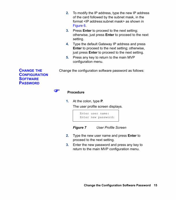
2. To modify the IP address, type the new IP address of the card followed by the subnet mask, in the format <IP address:subnet mask> as shown in Figure 6.
3. Press Enter to proceed to the next setting; otherwise, just press Enter to proceed to the next setting.
4. Type the default Gateway IP address and press Enter to proceed to the next setting; otherwise, just press Enter to proceed to the next setting.
5. Press any key to return to the main MVP configuration menu.
CHANGE THE CONFIGURATION SOFTWARE PASSWORD
Change the configuration software password as follows:
Procedure
1. At the colon, type P.The user profile screen displays.
Figure 7 User Profile Screen
2. Type the new user name and press Enter to proceed to the next setting.
3. Enter the new password and press any key to return to the main MVP configuration menu.
Enter user name: Enter new password:
Change the Configuration Software Password 15
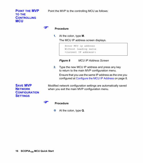
POINT THE MVP TO THE CONTROLLING MCU
Point the MVP to the controlling MCU as follows:
Procedure
1. At the colon, type M.The MCU IP address screen displays.
Figure 8 MCU IP Address Screen
2. Type the new MCU IP address and press any key to return to the main MVP configuration menu.Ensure that you use the same IP address as the one you configured at Configure the MCU IP Address on page 8.
SAVE MVP NETWORK CONFIGURATION SETTINGS
Modified network configuration settings are automatically saved when you exit the main MVP configuration menu.
Procedure
At the colon, type Q.
Enter MCU ip addressWithout leading zeros<current IP address>:
16 SCOPIA100 MCU Quick Start
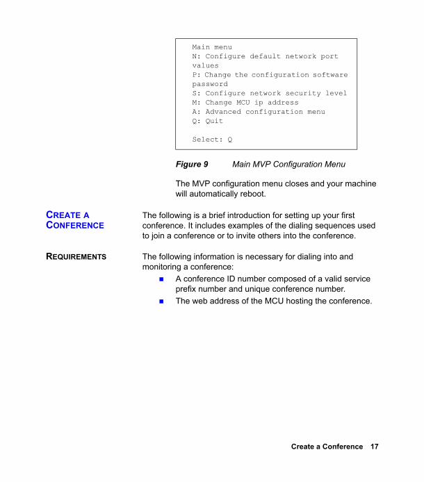
Figure 9 Main MVP Configuration Menu
The MVP configuration menu closes and your machine will automatically reboot.
CREATE A CONFERENCE
The following is a brief introduction for setting up your first conference. It includes examples of the dialing sequences used to join a conference or to invite others into the conference.
REQUIREMENTS The following information is necessary for dialing into and monitoring a conference:
A conference ID number composed of a valid service prefix number and unique conference number.The web address of the MCU hosting the conference.
Main menuN: Configure default network port valuesP: Change the configuration software passwordS: Configure network security levelM: Change MCU ip addressA: Advanced configuration menuQ: Quit
Select: Q
Create a Conference 17
START A CONFERENCE
You can initiate a conference by dialing to the MCU directly from an H.323 or SIP terminal or through a gateway from an H.320 terminal, a 3G-H.324M terminal or a regular telephone. Upon conference initiation, the conference manager can either invite other participants into the conference or supply each participant with the conference ID number for dialing directly into the conference.
Procedure
1. Compose a conference ID number using an appropriate service prefix and a unique ID number up to 256 characters long.
2. Notify all conference participants of the conference ID number. Users joining the conference via gateways also need to know a gateway phone number.
3. To start the conference dial the following:<service prefix>+<unique ID number>. For example, 605793, where 60 is the service prefix, and 1234 is the unique ID number.As soon as the MCU accepts the call, the conference is established.
18 SCOPIA100 MCU Quick Start