Embed Size (px)
Citation preview
Scour and Scour MitigationHollandse Kust (zuid) Wind Farm ZoneTechnical Note
1 van 1
RVO.nl distribution Document title: Scour and Scour Mitigation Document subtitle: Hollandse Kust (zuid) Wind Farm Zone Technical Note Author (s): Deltares Contract manager RVO.nl: Frank van Erp Project ID RVO.nl: WOZ2170029 Number of pages: 78 pages
Version
Approved for public disclosure by contract manager RVO.nl
Approved for public disclosure by project manager offshore wind RVO.nl
Final
Name Frank van Erp Signature Date
Name Ruud de Bruijne Signature Date
05-10-2017
Scour and scour mitigation for Hollandse Kust (zuid)Recommendations for foundations and cables
Final reportSeptember 2017

Scour and scour mitigation for Hollandse Kust (zuid) Recommendations for foundations and cables
11200864-002 © Deltares, 2017, B
Tim Raaijmakers Tom Roetert Pim van Steijn

Title Scour and scour mitigation for Hollandse Kust (zuid) Client Rijksdienst voor Ondernemend Nederland
Project 11200864-002
Reference 11200864-002-HYE-0001
Pages 64
Scour and scour mitigation for Hollandse Kust (zuid)
Keywords Scour, scour protection, morphodynamics, Hollandse Kust (zuid) Summary This report provides general considerations on how to deal with scour development and scour mitigation in Hollandse Kust (zuid), taking into account the morphodynamic character of the area (the presence of migrating sand waves) and a range of potential types of foundations. Also general considerations for cable routing in a morphodynamic environment are provided. The report first describes possible scour mitigation strategies (Chapter 3). Offshore structures can either be protected against scour or be designed such that scour development can be allowed. First, the scour mitigation strategies are illustrated for stable seabeds, which are valid for areas with small morphodynamic activity. Secondly, the strategies are extended taking into account morphodynamic activity. To decide which strategy can best be adopted for a certain foundation type and specific location, more accurate input is required a) for the expected scour depth (to be able to compute the necessary modifications to the structure to be able to deal with scour) and b) for the minimum required scour protection to prevent scour from occurring. Chapter 4 discusses scour predictions for a variety of foundations in HKZ, while Chapter 5 describes currently available scour protection methods. It can be concluded that for monopiles an easy-applicable, well-proven solution is to place the monopiles just north-east of the sand wave crests or even on top of the sand wave crests and to apply a scour protection to maintain a more or less fixed seabed level around the foundation. In the first case a slightly longer pile is needed, while in the second case a longer extent of the scour protection is recommended to cater for the lowering seabed. Gravity-Based-Structures will typically need a scour protection due to too severe scour development in the mobile seabeds in HKZ and the low tolerance for scour due to undermining risks; locations with a significantly lowering seabed are best to be avoided for GBS. Jacket structures are expected to experience significant scour development as well, but as long as they are not located in areas with lowering seabeds and cable free spanning risks are mitigated by proper cable protection measures (such as cable stiffeners) they can be designed for free scour development. This does not hold for Suction Bucket Jackets: due to the limited penetration depth of the suction cans, scour protection is in most cases recommended in HKZ. Self-installable systems look promising here. Next to foundations, this report also discusses general considerations for cable routing in a morphodynamic area such as HKZ (Chapter 6). It is expected that cables can be buried sufficiently deep to avoid cable exposure, when smart cable routing techniques are adopted, which avoid the areas with largest morphodynamic seabed lowering or other “expensive” areas. References Request for proposal: Scour study Hollandse Kust, ref. WOZ21706W4ZKU/ML, dated 10-02-2017 Proposal: Scour study Hollandse Kust (zuid), reference 11200864-001-HYE-0001, dated 6-03-2017 Award: ref. WOZ21706Z5IWU/ML, dated 4-04-2017, and ref. WOZ217071GHYU/MC, dated 3-05-2017 Version Date Author Initials Review Initials Approval Initials draft 31 August 2017 Tim Raaijmakers Hans de Vroeg Klaas Jan Bos final 27 September 2017 Tom Roetert Pim van Steijn State final

11200864-002-HYE-0001, 27 September 2017, final
Scour and scour mitigation for Hollandse Kust (zuid)
i
Contents
1 Introduction 1 1.1 Background 1 1.2 Study Objectives 1 1.3 Content of report 1
2 Site description 2 2.1 Site location and seabed composition 2 2.2 Seabed morphodynamics 3 2.3 Hydrodynamics 5
3 Scour mitigation strategies 8 3.1 Introduction 8 3.2 Scour mitigation strategies excluding morphodynamics of the seabed 9
3.2.1 Strategy A: Free scour development 9 3.2.2 Strategy B: Immediate scour protection 10 3.2.3 Strategy C: Monitor and React 10
3.3 Scour mitigation strategies including morphodynamics of the seabed 11 3.3.1 Strategy A: Free scour development 12 3.3.2 Strategy B: Immediate scour protection 13 3.3.3 Strategy C: Monitor and React 14
3.4 Recommendations regarding possible scour mitigation strategies for HKZ 15
4 Scour prediction for selected foundations 17 4.1 Introduction 17 4.2 Definitions of scour types 18 4.3 General description of local scour processes 19 4.4 Scour potential in HKZWFZ 20 4.5 Scour at monopiles 21
4.5.1 Introduction Scour Prediction Model 21 4.5.2 Validation Scour Prediction Model 22 4.5.3 Scour predictions for HKZWFZ using Scour Prediction Model 25
4.6 Scour at piled jacket structures 28 4.7 Scour at Suction Bucket Jackets 29 4.8 Scour at Gravity Based Structures 30 4.9 Scour at jack-up platforms with spud can footings 31
4.9.1 Introduction to jack-up scour 31 4.9.2 OSCAR software 32 4.9.3 Example computations for scour depth around spud cans 34
4.10 Edge scour around scour protections 35
5 Scour protection methods 39 5.1 Introduction 39 5.2 Design requirements for a scour protection 39 5.3 Evaluation criteria for selection of scour protection method 41 5.4 Static scour protection consisting of rock 42 5.5 Dynamic scour protection with two gradings of loose rock 43 5.6 Dynamic scour protection with a single grading of loose rock 44

ii
11200864-002-HYE-0001, 27 September 2017, final
Scour and scour mitigation for Hollandse Kust (zuid)
5.7 Artificial vegetation 45 5.8 Concrete block mattresses 47 5.9 Gabions 48 5.10 Geotubes and Geocontainers 49 5.11 Rock-filled mesh bags 50 5.12 Gravel bags 51 5.13 Ground Consolidators or Geohooks 52 5.14 Mattresses of rubber tyres 53
6 Cable routing in morphodynamic environments 55 6.1 Introduction 55 6.2 Sand wave migration 55 6.3 Cable routing 57
6.3.1 Overall wind farm cable layout 57 6.3.2 Cable routing of individual inter-array cables 57
7 Conclusions and recommendations 62 7.1 Conclusions 62 7.2 Recommendations 63
References 63
11200864-002-HYE-0001, 27 September 2017, final
Scour and scour mitigation for Hollandse Kust (zuid)
1 of 64
1 Introduction
1.1 Background In 2016 Deltares performed a study on the morphodynamics of the Hollandse Kust (zuid) wind farm zones (HKZWFZ). In this study seabed changes due to autonomous morphodynamic processes (such as migrating sand waves) were investigated and reference seabed levels were defined. The next step is to interpret this data to determine optimum locations for the wind turbine foundations and cable trajectories and to define proper mitigation strategies for scour development and morphodynamic seabed changes. To support these next steps, the Netherlands Enterprise Agency (RVO.nl) requested Deltares to provide general considerations on scour and scour mitigation measures taking into account the morphodynamic character of the seabed in HKZWFZ.
1.2 Study Objectives The objectives of this study are: 1. To describe the scour conditions to be expected at Hollandse Kust (zuid) for typical wind
farm-related structures; 2. To provide a state-of-the-art overview of scour mitigation measures and their applicability
at HKZ at these structures; 3. To provide guidance on how the morphodynamics should be taken into account for the
selection of the structure’s location and scour mitigation strategy. Note that structure is here both interpreted as a wind turbine support structure and as an infield electricity cable. Offshore High Voltage Stations and the export cables are not considered part of the scope.
1.3 Content of report This report starts with a site description in Chapter 2. This description focuses on the main parameters related to scour and morphodynamics: site location and seabed composition in Section 2.1, seabed morphodynamics and design seabed levels in Section 2.2 and hydrodynamics in Section 2.3. In Chapter 3 the scour mitigation strategies are described. First mitigation strategies excluding morphodynamics will be described in Section 3.2; then the more complicated strategies for the situation including morphodynamics will be discussed in Section 3.3. Recommendations specifically for HKZWFZ are presented in Section 3.4. Dependent on the selected scour mitigation strategy, the focus should either be directed towards accurate scour prediction (Chapter 4) or towards available scour protection methods (Chapter 5). Some strategies rely on a combination of scour development and scour protection; then both Chapters 4 and 5 are relevant. Besides support structures electricity cables need to be installed in HKZWFZ. Since it is impossible to completely avoid morphodynamically active areas, it is advised to include morphodynamics in cable routing optimization, while minimizing risks and costs (Chapter 6). Conclusions and recommendations are drawn in Chapter 7. Wherever possible or available, the different concepts are illustrated by results of laboratory experiments or field measurements in nearby wind farms.
Scour and scour mitigation for Hollandse Kust (zuid)
11200864-002-HYE-0001, 27 September 2017, final
2 of 64
2 Site description
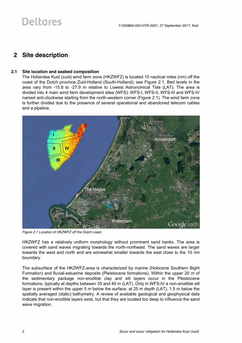
2.1 Site location and seabed composition The Hollandse Kust (zuid) wind farm zone (HKZWFZ) is located 10 nautical miles (nm) off the coast of the Dutch province Zuid-Holland (South-Holland); see Figure 2.1. Bed levels in the area vary from -15.8 to -27.9 m relative to Lowest Astronomical Tide (LAT). The area is divided into 4 main wind farm development sites (WFS): WFS-I, WFS-II, WFS-III and WFS-IV named anti-clockwise starting from the north-western corner (Figure 2.1). The wind farm zone is further divided due to the presence of several operational and abandoned telecom cables and a pipeline.
Figure 2.1 Location of HKZWFZ off the Dutch coast. HKZWFZ has a relatively uniform morphology without prominent sand banks. The area is covered with sand waves migrating towards the north-northeast. The sand waves are larger towards the west and north and are somewhat smaller towards the east close to the 10 nm boundary. The subsurface of the HKZWFZ-area is characterized by marine (Holocene Southern Bight Formation) and fluvial-estuarine deposits (Pleistocene formations). Within the upper 20 m of the sedimentary package non-erodible clay and silt layers occur in the Pleistocene formations, typically at depths between 35 and 40 m (LAT). Only in WFS-IV a non-erodible silt layer is present within the upper 5 m below the surface, at 25 m depth (LAT), 1.5 m below the spatially averaged (static) bathymetry. A review of available geological and geophysical data indicate that non-erodible layers exist, but that they are located too deep to influence the sand wave migration.
Amsterdam
Rotterdam
The Hague
I
II IV
III
11200864-002-HYE-0001, 27 September 2017, final
Scour and scour mitigation for Hollandse Kust (zuid)
3 of 64
The sediment grain size varies from fine-medium to medium-coarse sand at the seafloor and within the upper meter below the seafloor. The coarsest sediments (medium to coarse sand) are present in the south (WFS-III) and in two small areas in WFS-II and WFS-IV. In general, it can be concluded that the entire area consists of a mobile seabed and as a consequence is susceptible to scour (see Section 4.4). Since non-erodible layers are not present at limited depth, in this study it will be assumed that scour will not be limited by geology and that scour will occur in fine to medium sands. Since in this range of grain diameters (d50 = 125-500 µm) the sensitivity of the scour depth is relatively limited to the actual grain size, a constant diameter of d50 ≈ 200 µm is assumed in this study.
2.2 Seabed morphodynamics A detailed analysis of HKZWFZ seabed morphodynamics is presented in Deltares (2016). In this study the main focus was on the mobile parts of the seabed (sand waves and megaripples): their dimensions and migrations speeds were assessed in a detailed analysis. Since megaripples have migration speeds that are so large that many megaripples will pass at each foundation throughout the lifetime of wind farms, it was decided not to predict megaripple migration but to include some statistical values representing their heights in the uncertainty band. For structural design that implies that regardless of the adopted scour mitigation strategy seabed fluctuations in the order of the megaripple height need to be accounted for. In HKZWFZ, megaripples were almost absent on the nearshore side (WFS-IV and the eastern parts of WFS-I and WFS-III), while they reach heights up to 0.5m and lengths up to 20 m on the offshore side of HKZ. Considering the entire HKZWFZ, the sand waves have wavelengths in the range of 200 to 1000 m, heights of 1.1 to 4 m and typical migration speeds of 0.7 m/year to 3.0 m/year. In general sand waves migrate in north-north-eastern direction, their migration speeds increase from south to north and locally migration speeds up to 5.2 m/year are observed. For the development of wind turbine support structures, electricity cables and high voltage stations, a Best Estimate Bathymetry (BEB), a Lowest SeaBed Level (LSBL) and a Highest SeaBed Level (HSBL) were estimated. The BEB represents the predicted bathymetry for a certain year with the smallest expected average error. The LSBL and HSBL indicate the lowest and highest seabed levels, respectively, for the period 2016-2051, including uncertainty bands. The resulting LSBL showed a bathymetric shape similar to the existing static part of the bathymetry, but typically a few meters lower. Comparison of the LSBL with the most recent bathymetry from 2016 showed a predicted maximum local seabed level lowering of approximately 3.5 m. As expected, the largest lowering is found at the location of the existing sand wave crests, while minimal lowering is found at the location of the sand wave troughs. The HSBL showed a bathymetric shape similar to the existing static part of the bathymetry, but typically several meters higher and locally as much as 6.9 m. Opposite to the seabed lowering, the largest potential rise of the seabed level was found at the current locations of the troughs just in front of the steep sand wave lee sides, with minimal rising at locations of the present sand wave crests. In order to assess the relative influence of seabed level changes, the predicted seabed level lowering and rising were translated into classification zones for foundations and electricity cables. Different classification zones were based on the predicted seabed level lowering or
Scour and scour mitigation for Hollandse Kust (zuid)
11200864-002-HYE-0001, 27 September 2017, final
4 of 64
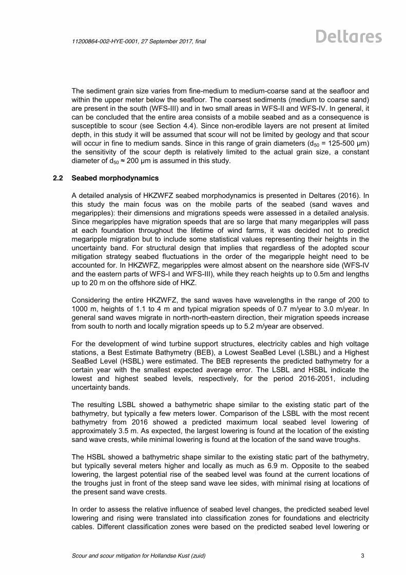
rising. Table 2.1 presents indicative values for both seabed lowering and seabed rising (as used in Deltares, 2016). The spatial distribution of the classification zones is displayed in Figure 2.2; a zoom plot is presented in Figure 2.3. Such classification zones can be determined both for foundations and for cables, although the actual values for lowering and rising may differ. Besides, the chosen foundation type or cable design will determine the sensitivity to seabed lowering and rising. The classification was chosen less restrictively for rising seabed levels, because close to the structures, local scour will counteract rising seabed levels. This does not apply to electricity cables, which are buried in the seabed; rising seabed levels can be of influence on the maximum cable temperature. Note that these classifications are for indicative and illustration purposes only. The actual classification is dependent on the design of the support structures and properties of electricity cables and should be adjusted accordingly once this information is available. It is therefore always recommended to re-consider these classification values and the consequences for foundation locations and cable trajectories in later design stages.
Classification of zones Bed level lowering [m] Bed level rising [m] Preferred 0 > dz ≥ -1 0 < dz ≤ 1 Possible -1 > dz ≥ -1.5 1 < dz ≤ 2
Better avoided -1.5 > dz ≥ -2 2 < dz ≤ 3 Un-recommended dz < -2 dz > 3
Table 2.1 Indicative classification zones for bed level lowering and rising [taken from Deltares, 2016]; actual values depend on foundation type, cable design, chosen risk profile and preference between capital and operational expenditures; it is recommended to re-consider these values in later design stages.
Figure 2.2 Overview map of classification zones based on combined classification for both highest and lowest
seabed levels for HKZWFZ. The grey patched area in the northeast is a sand mining area and was therefore excluded from the analysis.
11200864-002-HYE-0001, 27 September 2017, final
Scour and scour mitigation for Hollandse Kust (zuid)
5 of 64
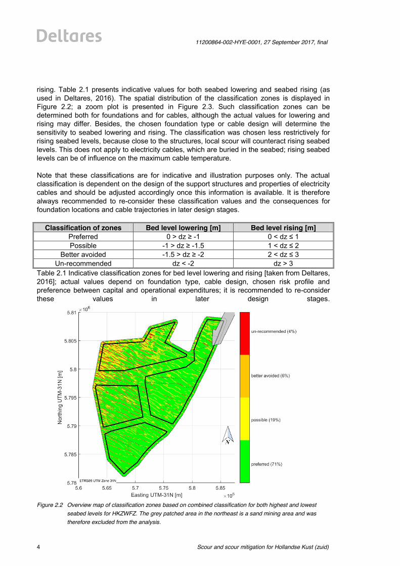
Figure 2.3 Zoom plot of classification zones based on combined classification for both highest and lowest seabed
levels for part of WFS-I of HKZWFZ.
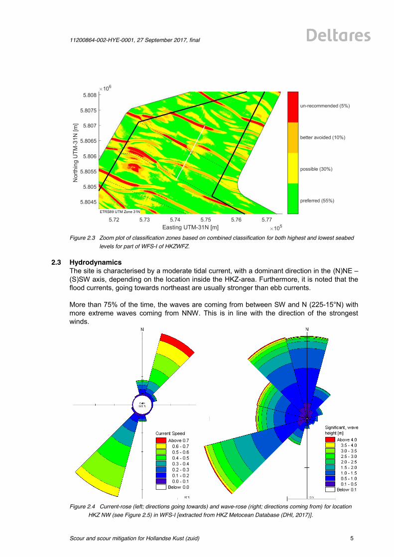
2.3 Hydrodynamics The site is characterised by a moderate tidal current, with a dominant direction in the (N)NE – (S)SW axis, depending on the location inside the HKZ-area. Furthermore, it is noted that the flood currents, going towards northeast are usually stronger than ebb currents. More than 75% of the time, the waves are coming from between SW and N (225-15°N) with more extreme waves coming from NNW. This is in line with the direction of the strongest winds.
Figure 2.4 Current-rose (left; directions going towards) and wave-rose (right; directions coming from) for location
HKZ NW (see Figure 2.5) in WFS-I [extracted from HKZ Metocean Database (DHI, 2017)].
Scour and scour mitigation for Hollandse Kust (zuid)
11200864-002-HYE-0001, 27 September 2017, final
6 of 64
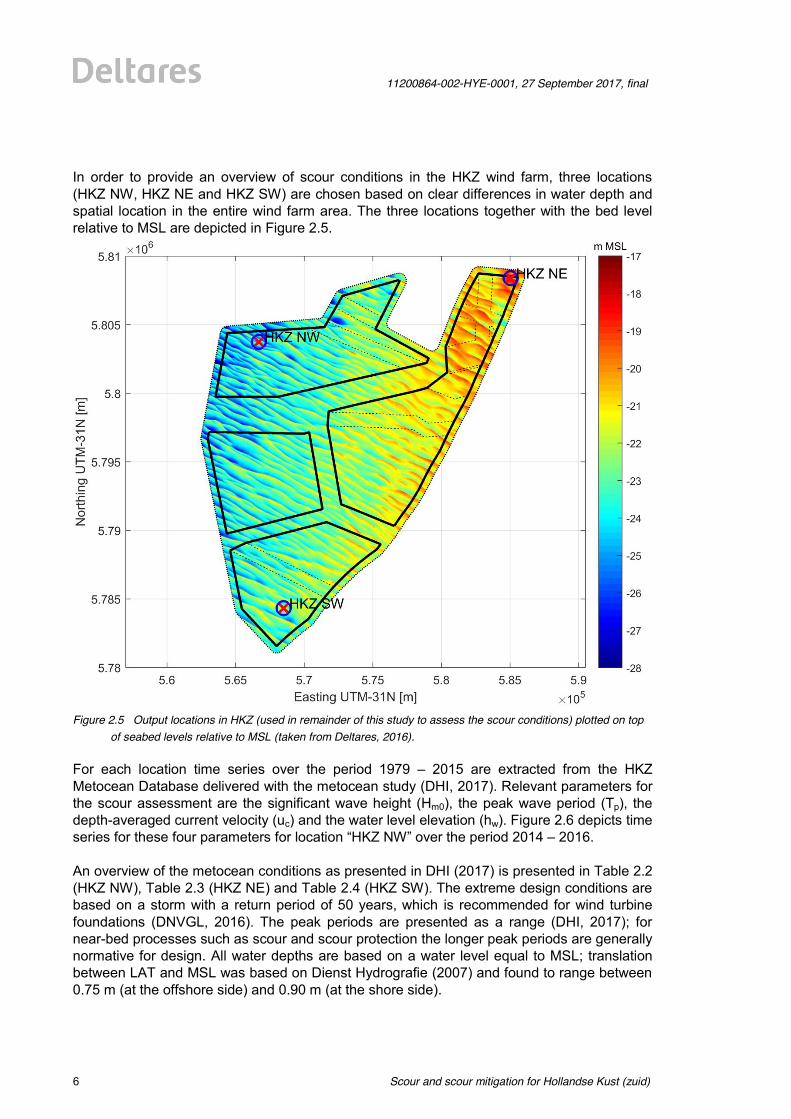
In order to provide an overview of scour conditions in the HKZ wind farm, three locations (HKZ NW, HKZ NE and HKZ SW) are chosen based on clear differences in water depth and spatial location in the entire wind farm area. The three locations together with the bed level relative to MSL are depicted in Figure 2.5.
Figure 2.5 Output locations in HKZ (used in remainder of this study to assess the scour conditions) plotted on top
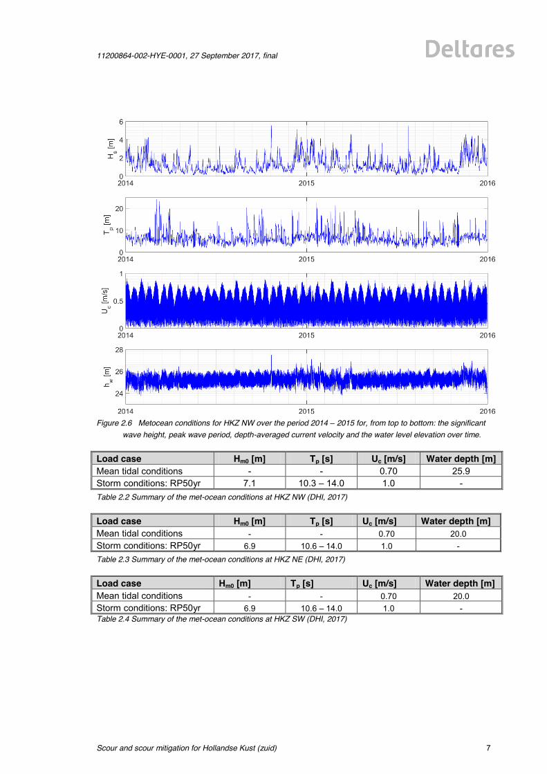
of seabed levels relative to MSL (taken from Deltares, 2016). For each location time series over the period 1979 – 2015 are extracted from the HKZ Metocean Database delivered with the metocean study (DHI, 2017). Relevant parameters for the scour assessment are the significant wave height (Hm0), the peak wave period (Tp), the depth-averaged current velocity (uc) and the water level elevation (hw). Figure 2.6 depicts time series for these four parameters for location “HKZ NW” over the period 2014 – 2016. An overview of the metocean conditions as presented in DHI (2017) is presented in Table 2.2 (HKZ NW), Table 2.3 (HKZ NE) and Table 2.4 (HKZ SW). The extreme design conditions are based on a storm with a return period of 50 years, which is recommended for wind turbine foundations (DNVGL, 2016). The peak periods are presented as a range (DHI, 2017); for near-bed processes such as scour and scour protection the longer peak periods are generally normative for design. All water depths are based on a water level equal to MSL; translation between LAT and MSL was based on Dienst Hydrografie (2007) and found to range between 0.75 m (at the offshore side) and 0.90 m (at the shore side).
11200864-002-HYE-0001, 27 September 2017, final
Scour and scour mitigation for Hollandse Kust (zuid)
7 of 64
Figure 2.6 Metocean conditions for HKZ NW over the period 2014 – 2015 for, from top to bottom: the significant
wave height, peak wave period, depth-averaged current velocity and the water level elevation over time. Load case Hm0 [m] Tp [s] Uc [m/s] Water depth [m] Mean tidal conditions - - 0.70 25.9 Storm conditions: RP50yr 7.1 10.3 – 14.0 1.0 - Table 2.2 Summary of the met-ocean conditions at HKZ NW (DHI, 2017) Load case Hm0 [m] Tp [s] Uc [m/s] Water depth [m] Mean tidal conditions - - 0.70 20.0 Storm conditions: RP50yr 6.9 10.6 – 14.0 1.0 - Table 2.3 Summary of the met-ocean conditions at HKZ NE (DHI, 2017) Load case Hm0 [m] Tp [s] Uc [m/s] Water depth [m] Mean tidal conditions - - 0.70 20.0 Storm conditions: RP50yr 6.9 10.6 – 14.0 1.0 - Table 2.4 Summary of the met-ocean conditions at HKZ SW (DHI, 2017)
Scour and scour mitigation for Hollandse Kust (zuid)
11200864-002-HYE-0001, 27 September 2017, final
8 of 64
3 Scour mitigation strategies
3.1 Introduction A designer of offshore wind turbine foundations always has to consider the potential for scour development around the foundation. Scour is the phenomenon that seabed sediments are eroding around the base of the foundation caused by the action of hydrodynamics. Scour will, for piled foundations, lower the pile fixation level or, for sit-on-bottom structures, cause undermining of the foundations. The expected scour development depends on many different parameters, such as structural dimensions and shapes, seabed composition and hydrodynamic climate. For the location of HKZWFZ it holds that both the seabed composition and the hydrodynamic climate are ‘favourable’ for scour development; this topic of predicting scour development for various foundation types is addressed in more detail in Chapter 4. Once the predicted scour depth is known, the designer has to choose whether he accepts that scour will occur and that he adjusts the foundation design to be able to cope with a lowering seabed level. As will be shown in Chapter 4, this option is more viable for one foundation type than the other. If the designer chooses to protect the foundation against scour by installing a scour protection, then multiple strategies can be taken, differentiating between the moment of installation and the type of scour protection applied. The strategies related to timing will be explained in this chapter, whereas the different scour protection methods will be discussed in Chapter 5. This chapter will first introduce the possible scour mitigation strategies in order to set the framework for the more in-depth chapters that will follow. Several classifications of mitigation strategies will be specified that can then be referred to, when discussing the applicability of certain measures later in this report. In Section 3.2 the scour mitigation strategies will first be explained for areas with a more or less stable seabed for the entire lifetime of the wind farm; this assumption can both be true for entire wind farms in areas with limited morphodynamic activity (e.g. many areas in the German Bight or Baltic Sea) or for carefully selected foundation locations in areas with significant morphodynamic activity; the latter applies to areas such as HKZWFZ. Since many wind farms are (for large parts) characterized by significant, not-to-be-neglected morphodynamic activity, the scour mitigation strategies are extended for areas with a lowering or rising seabed in Section 3.3. For HKZ many different foundation types can be considered. It was chosen to use the monopile foundation for illustration of the different scour mitigation strategies. The reason for this choice is threefold: 1) monopiles are still by far the most commonly applied foundation type for offshore wind turbines; 2) monopiles seem to be a logical foundation type for application in HKZWFZ because of the combination of soil type and water depth (note that the surrounding wind farms are all using monopile foundations); 3) at monopile foundations all of the presented mitigation strategies can be applied. However, other foundation types can be applied as well and also for these types several scour mitigation strategies can be adopted. For each of the other foundation types discussed in Chapter 4 the most promising scour mitigation strategies will be mentioned.
11200864-002-HYE-0001, 27 September 2017, final
Scour and scour mitigation for Hollandse Kust (zuid)
9 of 64
3.2 Scour mitigation strategies excluding morphodynamics of the seabed Before including the full complexity of autonomous morphological processes, first scour mitigation strategies will be developed for (more or less) stationary seabeds. For HKZWFZ this means that the sites need to be selected that are characterized by less than 1 m seabed change during the lifetime of the wind farm. Or, in case the design allows for rising seabeds (see also Section 3.3 for more explanation), this criterion can be narrowed down to “less than 1 m seabed lowering during the lifetime of the wind farm”. Whether an offshore structure needs to be protected is a matter of cost efficiency and risks. The following strategies can be adopted:
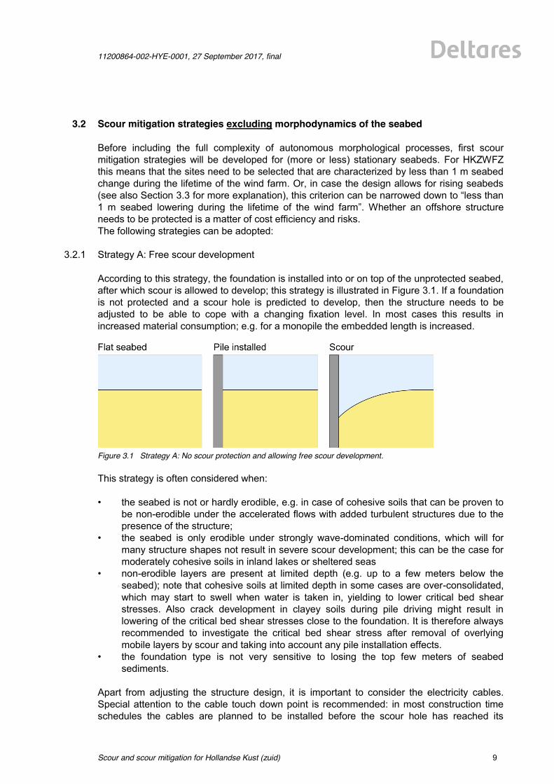
3.2.1 Strategy A: Free scour development According to this strategy, the foundation is installed into or on top of the unprotected seabed, after which scour is allowed to develop; this strategy is illustrated in Figure 3.1. If a foundation is not protected and a scour hole is predicted to develop, then the structure needs to be adjusted to be able to cope with a changing fixation level. In most cases this results in increased material consumption; e.g. for a monopile the embedded length is increased.
Figure 3.1 Strategy A: No scour protection and allowing free scour development. This strategy is often considered when: • the seabed is not or hardly erodible, e.g. in case of cohesive soils that can be proven to
be non-erodible under the accelerated flows with added turbulent structures due to the presence of the structure;
• the seabed is only erodible under strongly wave-dominated conditions, which will for many structure shapes not result in severe scour development; this can be the case for moderately cohesive soils in inland lakes or sheltered seas
• non-erodible layers are present at limited depth (e.g. up to a few meters below the seabed); note that cohesive soils at limited depth in some cases are over-consolidated, which may start to swell when water is taken in, yielding to lower critical bed shear stresses. Also crack development in clayey soils during pile driving might result in lowering of the critical bed shear stresses close to the foundation. It is therefore always recommended to investigate the critical bed shear stress after removal of overlying mobile layers by scour and taking into account any pile installation effects.
• the foundation type is not very sensitive to losing the top few meters of seabed sediments.
Apart from adjusting the structure design, it is important to consider the electricity cables. Special attention to the cable touch down point is recommended: in most construction time schedules the cables are planned to be installed before the scour hole has reached its
Scour and scour mitigation for Hollandse Kust (zuid)
11200864-002-HYE-0001, 27 September 2017, final
10 of 64
equilibrium. This means that the cable touchdown point might lower in the months after cable installation. To assess this lowering both the shape of the predicted scour hole and the orientation of the cables needs to be considered. Please note that in some locations the scour holes will not be perfectly round, but more elliptic in shape.
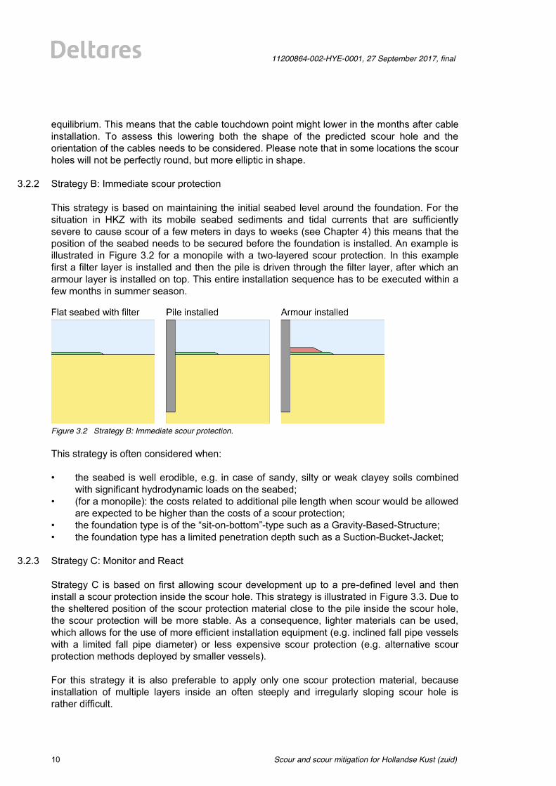
3.2.2 Strategy B: Immediate scour protection This strategy is based on maintaining the initial seabed level around the foundation. For the situation in HKZ with its mobile seabed sediments and tidal currents that are sufficiently severe to cause scour of a few meters in days to weeks (see Chapter 4) this means that the position of the seabed needs to be secured before the foundation is installed. An example is illustrated in Figure 3.2 for a monopile with a two-layered scour protection. In this example first a filter layer is installed and then the pile is driven through the filter layer, after which an armour layer is installed on top. This entire installation sequence has to be executed within a few months in summer season.
Figure 3.2 Strategy B: Immediate scour protection. This strategy is often considered when: • the seabed is well erodible, e.g. in case of sandy, silty or weak clayey soils combined
with significant hydrodynamic loads on the seabed; • (for a monopile): the costs related to additional pile length when scour would be allowed
are expected to be higher than the costs of a scour protection; • the foundation type is of the “sit-on-bottom”-type such as a Gravity-Based-Structure; • the foundation type has a limited penetration depth such as a Suction-Bucket-Jacket;
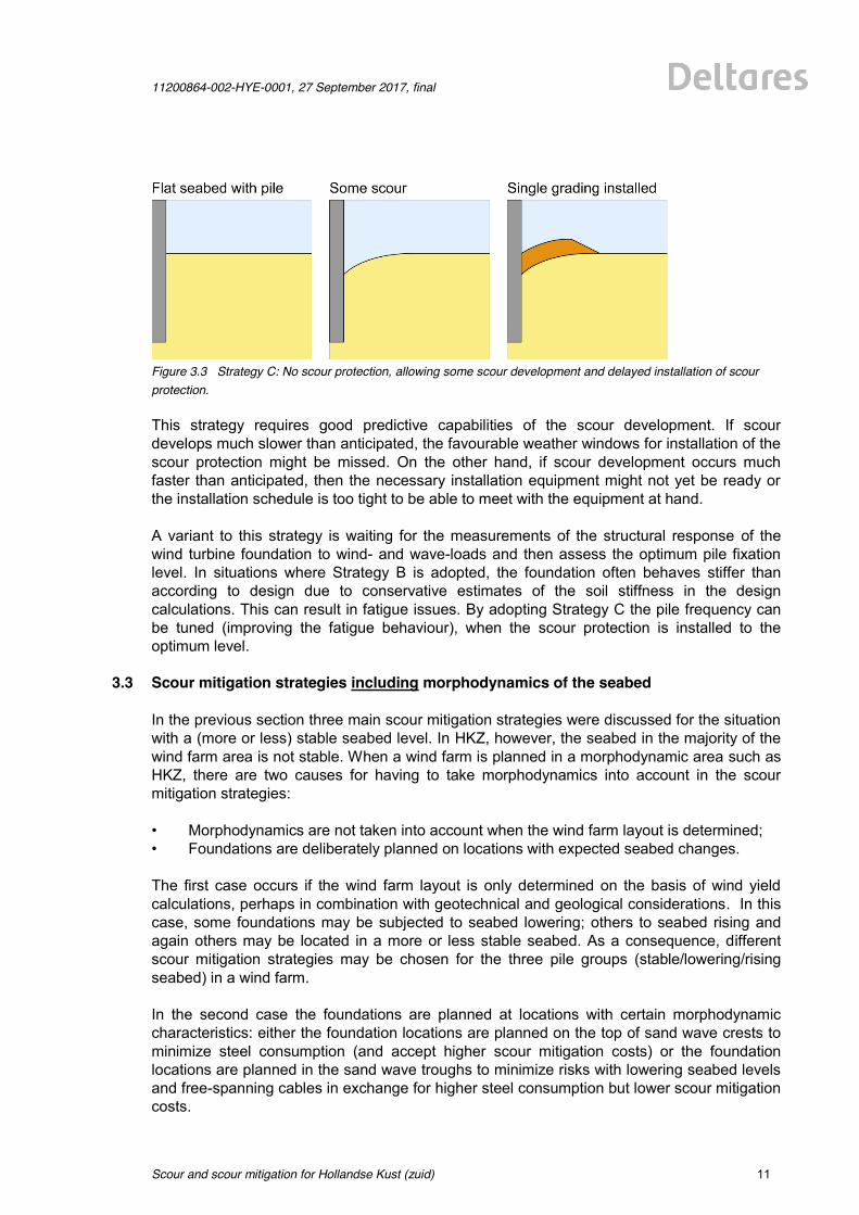
3.2.3 Strategy C: Monitor and React Strategy C is based on first allowing scour development up to a pre-defined level and then install a scour protection inside the scour hole. This strategy is illustrated in Figure 3.3. Due to the sheltered position of the scour protection material close to the pile inside the scour hole, the scour protection will be more stable. As a consequence, lighter materials can be used, which allows for the use of more efficient installation equipment (e.g. inclined fall pipe vessels with a limited fall pipe diameter) or less expensive scour protection (e.g. alternative scour protection methods deployed by smaller vessels). For this strategy it is also preferable to apply only one scour protection material, because installation of multiple layers inside an often steeply and irregularly sloping scour hole is rather difficult.
11200864-002-HYE-0001, 27 September 2017, final
Scour and scour mitigation for Hollandse Kust (zuid)
11 of 64
Figure 3.3 Strategy C: No scour protection, allowing some scour development and delayed installation of scour protection. This strategy requires good predictive capabilities of the scour development. If scour develops much slower than anticipated, the favourable weather windows for installation of the scour protection might be missed. On the other hand, if scour development occurs much faster than anticipated, then the necessary installation equipment might not yet be ready or the installation schedule is too tight to be able to meet with the equipment at hand. A variant to this strategy is waiting for the measurements of the structural response of the wind turbine foundation to wind- and wave-loads and then assess the optimum pile fixation level. In situations where Strategy B is adopted, the foundation often behaves stiffer than according to design due to conservative estimates of the soil stiffness in the design calculations. This can result in fatigue issues. By adopting Strategy C the pile frequency can be tuned (improving the fatigue behaviour), when the scour protection is installed to the optimum level.
3.3 Scour mitigation strategies including morphodynamics of the seabed In the previous section three main scour mitigation strategies were discussed for the situation with a (more or less) stable seabed level. In HKZ, however, the seabed in the majority of the wind farm area is not stable. When a wind farm is planned in a morphodynamic area such as HKZ, there are two causes for having to take morphodynamics into account in the scour mitigation strategies: • Morphodynamics are not taken into account when the wind farm layout is determined; • Foundations are deliberately planned on locations with expected seabed changes. The first case occurs if the wind farm layout is only determined on the basis of wind yield calculations, perhaps in combination with geotechnical and geological considerations. In this case, some foundations may be subjected to seabed lowering; others to seabed rising and again others may be located in a more or less stable seabed. As a consequence, different scour mitigation strategies may be chosen for the three pile groups (stable/lowering/rising seabed) in a wind farm. In the second case the foundations are planned at locations with certain morphodynamic characteristics: either the foundation locations are planned on the top of sand wave crests to minimize steel consumption (and accept higher scour mitigation costs) or the foundation locations are planned in the sand wave troughs to minimize risks with lowering seabed levels and free-spanning cables in exchange for higher steel consumption but lower scour mitigation costs.
Scour and scour mitigation for Hollandse Kust (zuid)
11200864-002-HYE-0001, 27 September 2017, final
12 of 64
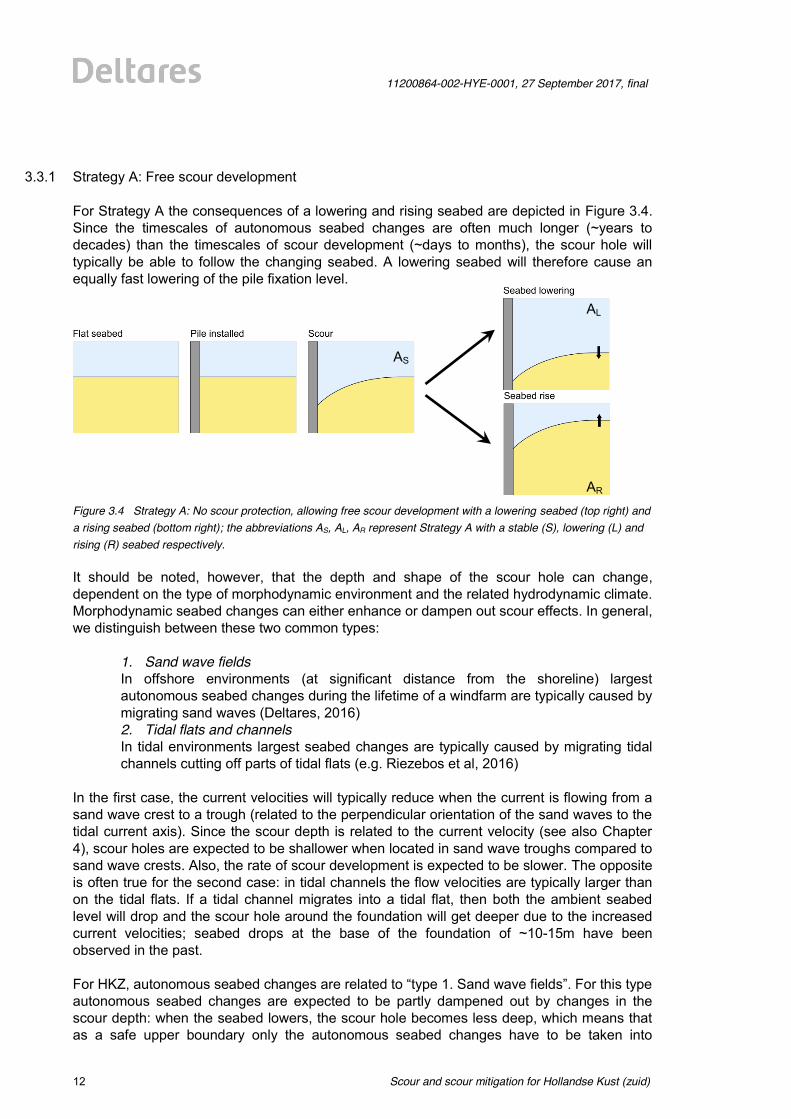
3.3.1 Strategy A: Free scour development For Strategy A the consequences of a lowering and rising seabed are depicted in Figure 3.4. Since the timescales of autonomous seabed changes are often much longer (~years to decades) than the timescales of scour development (~days to months), the scour hole will typically be able to follow the changing seabed. A lowering seabed will therefore cause an equally fast lowering of the pile fixation level.
Figure 3.4 Strategy A: No scour protection, allowing free scour development with a lowering seabed (top right) and a rising seabed (bottom right); the abbreviations AS, AL, AR represent Strategy A with a stable (S), lowering (L) and rising (R) seabed respectively. It should be noted, however, that the depth and shape of the scour hole can change, dependent on the type of morphodynamic environment and the related hydrodynamic climate. Morphodynamic seabed changes can either enhance or dampen out scour effects. In general, we distinguish between these two common types:
1. Sand wave fields In offshore environments (at significant distance from the shoreline) largest autonomous seabed changes during the lifetime of a windfarm are typically caused by migrating sand waves (Deltares, 2016) 2. Tidal flats and channels In tidal environments largest seabed changes are typically caused by migrating tidal channels cutting off parts of tidal flats (e.g. Riezebos et al, 2016)
In the first case, the current velocities will typically reduce when the current is flowing from a sand wave crest to a trough (related to the perpendicular orientation of the sand waves to the tidal current axis). Since the scour depth is related to the current velocity (see also Chapter 4), scour holes are expected to be shallower when located in sand wave troughs compared to sand wave crests. Also, the rate of scour development is expected to be slower. The opposite is often true for the second case: in tidal channels the flow velocities are typically larger than on the tidal flats. If a tidal channel migrates into a tidal flat, then both the ambient seabed level will drop and the scour hole around the foundation will get deeper due to the increased current velocities; seabed drops at the base of the foundation of ~10-15m have been observed in the past. For HKZ, autonomous seabed changes are related to “type 1. Sand wave fields”. For this type autonomous seabed changes are expected to be partly dampened out by changes in the scour depth: when the seabed lowers, the scour hole becomes less deep, which means that as a safe upper boundary only the autonomous seabed changes have to be taken into
AS
AL
AR
11200864-002-HYE-0001, 27 September 2017, final
Scour and scour mitigation for Hollandse Kust (zuid)
13 of 64
account without accounting for changes in scour depth, when variations in the fixation level are predicted (note that this fixation level is based on the developed scour depth for the initial ambient seabed level: situation AS).
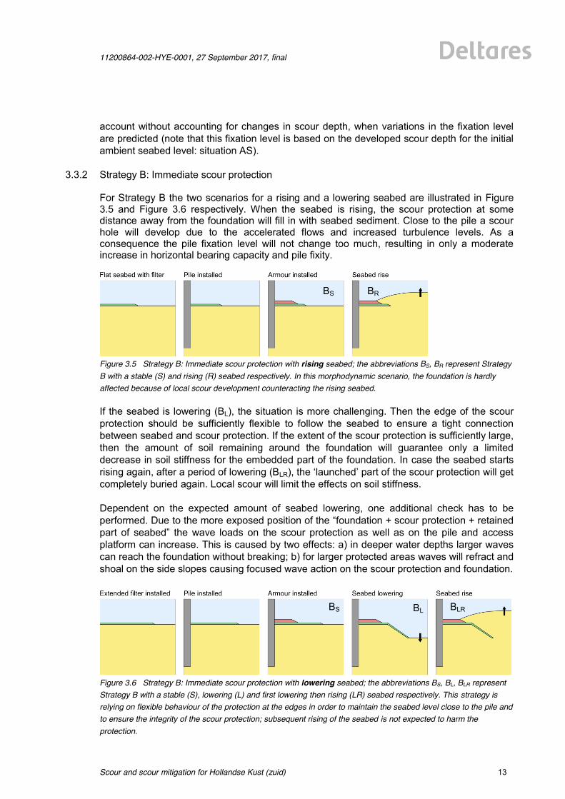
3.3.2 Strategy B: Immediate scour protection For Strategy B the two scenarios for a rising and a lowering seabed are illustrated in Figure 3.5 and Figure 3.6 respectively. When the seabed is rising, the scour protection at some distance away from the foundation will fill in with seabed sediment. Close to the pile a scour hole will develop due to the accelerated flows and increased turbulence levels. As a consequence the pile fixation level will not change too much, resulting in only a moderate increase in horizontal bearing capacity and pile fixity.
Figure 3.5 Strategy B: Immediate scour protection with rising seabed; the abbreviations BS, BR represent Strategy B with a stable (S) and rising (R) seabed respectively. In this morphodynamic scenario, the foundation is hardly affected because of local scour development counteracting the rising seabed. If the seabed is lowering (BL), the situation is more challenging. Then the edge of the scour protection should be sufficiently flexible to follow the seabed to ensure a tight connection between seabed and scour protection. If the extent of the scour protection is sufficiently large, then the amount of soil remaining around the foundation will guarantee only a limited decrease in soil stiffness for the embedded part of the foundation. In case the seabed starts rising again, after a period of lowering (BLR), the ‘launched’ part of the scour protection will get completely buried again. Local scour will limit the effects on soil stiffness. Dependent on the expected amount of seabed lowering, one additional check has to be performed. Due to the more exposed position of the “foundation + scour protection + retained part of seabed” the wave loads on the scour protection as well as on the pile and access platform can increase. This is caused by two effects: a) in deeper water depths larger waves can reach the foundation without breaking; b) for larger protected areas waves will refract and shoal on the side slopes causing focused wave action on the scour protection and foundation.
Figure 3.6 Strategy B: Immediate scour protection with lowering seabed; the abbreviations BS, BL, BLR represent Strategy B with a stable (S), lowering (L) and first lowering then rising (LR) seabed respectively. This strategy is relying on flexible behaviour of the protection at the edges in order to maintain the seabed level close to the pile and to ensure the integrity of the scour protection; subsequent rising of the seabed is not expected to harm the protection.
BS BR
BS BL BLR
Scour and scour mitigation for Hollandse Kust (zuid)
11200864-002-HYE-0001, 27 September 2017, final
14 of 64
In conclusion scour protections can be applied in areas with a lowering seabed, as long as the scour protection has good flexible behaviour at the edge and an extent carefully adjusted to the expected seabed drop. These three features will be addressed in Chapter 5, when the different scour protection concepts are discussed.
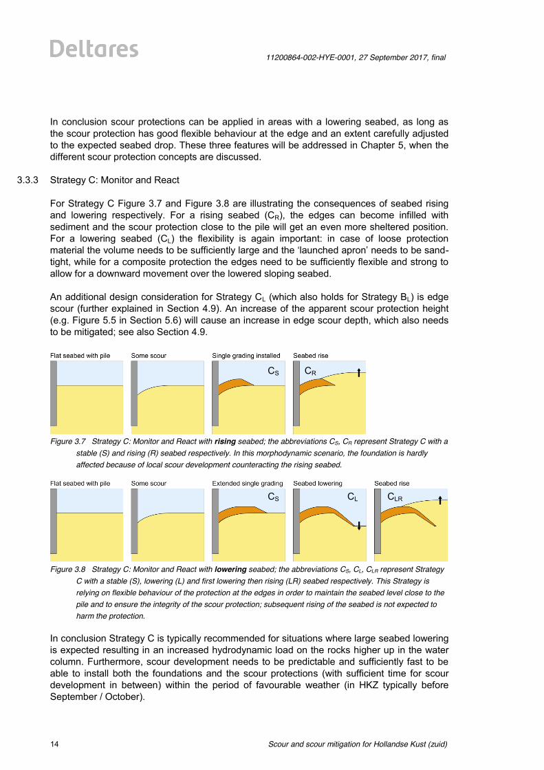
3.3.3 Strategy C: Monitor and React For Strategy C Figure 3.7 and Figure 3.8 are illustrating the consequences of seabed rising and lowering respectively. For a rising seabed (CR), the edges can become infilled with sediment and the scour protection close to the pile will get an even more sheltered position. For a lowering seabed (CL) the flexibility is again important: in case of loose protection material the volume needs to be sufficiently large and the ‘launched apron’ needs to be sand-tight, while for a composite protection the edges need to be sufficiently flexible and strong to allow for a downward movement over the lowered sloping seabed. An additional design consideration for Strategy CL (which also holds for Strategy BL) is edge scour (further explained in Section 4.9). An increase of the apparent scour protection height (e.g. Figure 5.5 in Section 5.6) will cause an increase in edge scour depth, which also needs to be mitigated; see also Section 4.9.
Figure 3.7 Strategy C: Monitor and React with rising seabed; the abbreviations CS, CR represent Strategy C with a
stable (S) and rising (R) seabed respectively. In this morphodynamic scenario, the foundation is hardly affected because of local scour development counteracting the rising seabed.
Figure 3.8 Strategy C: Monitor and React with lowering seabed; the abbreviations CS, CL, CLR represent Strategy
C with a stable (S), lowering (L) and first lowering then rising (LR) seabed respectively. This Strategy is relying on flexible behaviour of the protection at the edges in order to maintain the seabed level close to the pile and to ensure the integrity of the scour protection; subsequent rising of the seabed is not expected to harm the protection.
In conclusion Strategy C is typically recommended for situations where large seabed lowering is expected resulting in an increased hydrodynamic load on the rocks higher up in the water column. Furthermore, scour development needs to be predictable and sufficiently fast to be able to install both the foundations and the scour protections (with sufficient time for scour development in between) within the period of favourable weather (in HKZ typically before September / October).
CS CR
CS CL CLR
11200864-002-HYE-0001, 27 September 2017, final
Scour and scour mitigation for Hollandse Kust (zuid)
15 of 64
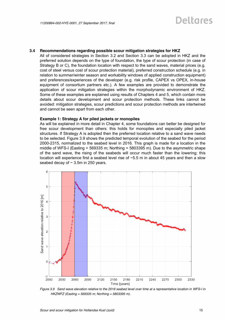
3.4 Recommendations regarding possible scour mitigation strategies for HKZ All of considered strategies in Section 3.2 and Section 3.3 can be adopted in HKZ and the preferred solution depends on the type of foundation, the type of scour protection (in case of Strategy B or C), the foundation location with respect to the sand waves, material prices (e.g. cost of steel versus cost of scour protection material), preferred construction schedule (e.g. in relation to summer/winter season and workability windows of applied construction equipment) and preferences/experiences of the developer (e.g. risk profile, CAPEX vs OPEX, in-house equipment of consortium partners etc.). A few examples are provided to demonstrate the application of scour mitigation strategies within the morphodynamic environment of HKZ. Some of these examples are explained using results of Chapters 4 and 5, which contain more details about scour development and scour protection methods. These links cannot be avoided: mitigation strategies, scour predictions and scour protection methods are intertwined and cannot be seen apart from each other. Example 1: Strategy A for piled jackets or monopiles As will be explained in more detail in Chapter 4, some foundations can better be designed for free scour development than others: this holds for monopiles and especially piled jacket structures. If Strategy A is adopted then the preferred location relative to a sand wave needs to be selected. Figure 3.9 shows the predicted temporal evolution of the seabed for the period 2000-2315, normalized to the seabed level in 2016. This graph is made for a location in the middle of WFS-I (Easting = 569335 m; Northing = 5803395 m). Due to the asymmetric shape of the sand wave, the rising of the seabeds will occur much faster than the lowering; this location will experience first a seabed level rise of ~5.5 m in about 45 years and then a slow seabed decay of ~ 3.5m in 250 years.
Figure 3.9 Sand wave elevation relative to the 2016 seabed level over time at a representative location in WFS-I in
HKZWFZ (Easting = 569335 m; Northing = 5803395 m).
Scour and scour mitigation for Hollandse Kust (zuid)
11200864-002-HYE-0001, 27 September 2017, final
16 of 64
For visual interpretation, the grid lines are divided in periods of 30 years, which is about equal to the lifetime of a wind farm. Additional two patches, both covering a 30 year period, are displayed. The red patch depicts the sand wave elevation around a foundation in case it is placed just southwest of the sand wave trough (lee side), resulting in a sand wave elevation increase of ~5 m in a 30 year period. The blue patch depicts the sand wave elevation around a monopile in case it is placed just northeast of the sand wave crest (lee side), resulting in a net sand wave elevation change of ~0 m over a 30 year period. When a foundation would be placed at this location in a sand wave trough then the foundation length has to be extended with the full sand wave height (~5.5 m), while this length is not necessary for a large part of the lifetime. When placed at the top of the sand wave crest around this example location, the seabed lowering due to morphodynamic processes will only be ~1 m during the lifetime. In this case the pile length only has to be increased with 1 m. Due to the expected negative feedback on the scour depth of morphodynamic seabed changes (explained in Section 3.3.1), a safe value for the minimum fixation level (rel. to MSL) can be determined as water depth (rel. to MSL) + scour depth that will develop for the seabed position at t0 + predicted seabed lowering during lifetime. Example 2: Strategy B for Gravity Based Structures A Gravity-Based-Structure (GBS) is an example of a structure which typically requires a scour protection (see also Section 4.8). Because of the large obstruction and large diameter, it is recommended to avoid areas with a lowering seabed (BL); this would require significant scour protection volumes. Areas with a stable seabed (BS), which can be found just NE of the sand wave trough (stoss side) are obviously possible, but they also require the largest foundation length. A cost optimization can be obtained by placing the GBS just NE of the sand wave crest, such that the GBS will first experience ~5 years of seabed rise, until the sand wave crest passes, and then seabed lowering for the rest of the lifetime. Example 3: Strategy C for monopiles Due to the limited seabed lowering during the lifetime, there is no real need to apply the more complicated Strategy C in HKZWFZ. Also because of the large predicted scour depth and the relatively fast scour development over the first few meters (Section 4.5), it is considered rather challenging to apply scour protection at exactly the right time: too late would mean that an excessive volume of scour protection material should be installed to still be able to reach the prescribed fixation level; too early would mean that the scour protection will not benefit fully from its sheltered position, resulting in the risk of too much deformation during storm conditions. An important benefit might be that a scour protection with limited volume consisting of a relatively small single grading can be applied (if executed properly).
11200864-002-HYE-0001, 27 September 2017, final
Scour and scour mitigation for Hollandse Kust (zuid)
17 of 64
4 Scour prediction for selected foundations
4.1 Introduction Before detailed scour predictions are made, first the scour potential in the area needs to be considered. Section 4.2 introduces some definitions of different types of scour, while Section 4.3 provides a generic description of scour and Section 4.4 will proof that the HKZ-area indeed is susceptible to scour. At this stage the types, shapes and dimensions of the support structures for the wind turbines to be placed in HKZ are not yet known. Also the foundation locations and hence the interaction with the seabed morphodynamics are not yet known. To still be able to provide the developers with some rough indications on what can be expected in terms of scour, we considered a variety of support structures and performed some indicative scour predictions for this particular site using the Deltares’ Scour Prediction Model. Estimated scour depths will be presented subsequently for monopiles (Section 4.5), piled jackets (Section 4.6), suction-bucket-jackets (Section 4.7), Gravity-Based-Structures (Section 4.8) and jack-up platforms with spud can footings (Section 4.9). In the last section of this chapter (Section 4.10) edge scour is introduced. The Scour Prediction Model that was applied is validated against a large amount of laboratory and field measurements. The highest accuracy can be expected for monopiles, for two reasons. Firstly, monopiles are the most commonly applied support structure and hence most laboratory and field measurements were available for this structure type. Secondly, monopiles have in terms of scour more or less similar designs that can be primarily described by the pile diameter. More complicated structures such as piled jackets and suction bucket jackets come in a wide variety of designs, with different leg configurations and diameters, pile-sleeve-connections, mud mats, braces, stiffeners etc. Scour development is very dependent on these structural details close to the seabed. As a consequence, scour predictions will always need to be based on the actual design. Therefore, in this study only ranges in scour depth are presented for these structure types. These values need to be updated in later design phases. In order to obtain more accurate scour predictions, besides more details on the foundation also the exact structure locations inside HKZWFZ need to be known. The location determines the hydrodynamics (compare a location offshore or more near-shore; or a location in a sand wave trough or on top of a sand wave crest). In this chapter, the effect of location is demonstrated by using the three locations introduced in Section 2.3. Because of these reasons, all values in this study should merely be considered as best-estimate values (without any safety factors!) to provide the developer with information to determine its scour mitigation strategy in an early stage. In later design stages the scour predictions should be updated for the exact locations and hydrodynamics and the exact structure shapes.
Scour and scour mitigation for Hollandse Kust (zuid)
11200864-002-HYE-0001, 27 September 2017, final
18 of 64
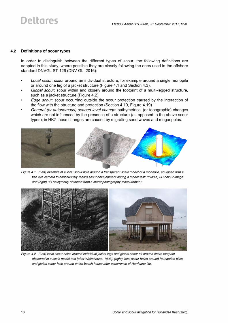
4.2 Definitions of scour types In order to distinguish between the different types of scour, the following definitions are adopted in this study, where possible they are closely following the ones used in the offshore standard DNVGL ST-126 (DNV GL, 2016): • Local scour: scour around an individual structure, for example around a single monopile
or around one leg of a jacket structure (Figure 4.1 and Section 4.3). • Global scour: scour within and closely around the footprint of a multi-legged structure,
such as a jacket structure (Figure 4.2) • Edge scour: scour occurring outside the scour protection caused by the interaction of
the flow with the structure and protection (Section 4.10, Figure 4.19) • General (or autonomous) seabed level change: bathymetrical (or topographic) changes
which are not influenced by the presence of a structure (as opposed to the above scour types); in HKZ these changes are caused by migrating sand waves and megaripples.
Figure 4.1 (Left) example of a local scour hole around a transparent scale model of a monopile, equipped with a
fish eye camera to continuously record scour development during a model test; (middle) 3D-colour image and (right) 3D bathymetry obtained from a stereophotography measurement.
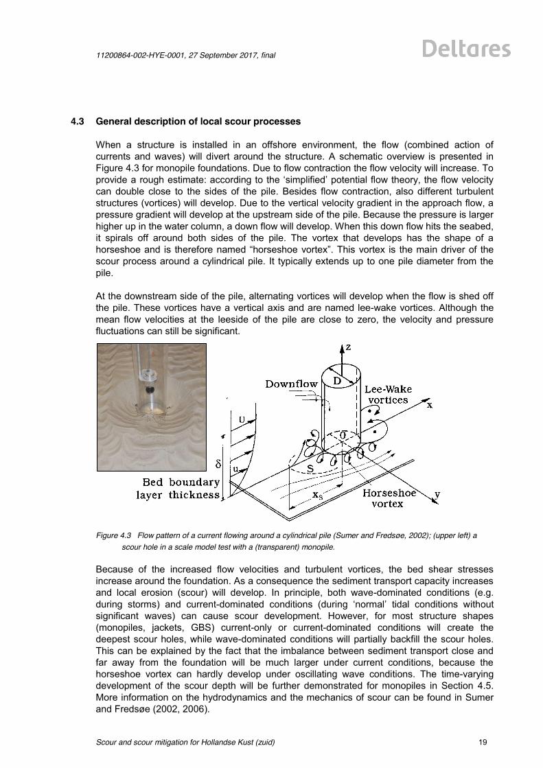
Figure 4.2 (Left) local scour holes around individual jacket legs and global scour pit around entire footprint
observed in a scale model test [after Whitehouse, 1998]; (right) local scour holes around foundation piles and global scour hole around entire beach house after occurrence of Hurricane Ike.
11200864-002-HYE-0001, 27 September 2017, final
Scour and scour mitigation for Hollandse Kust (zuid)
19 of 64
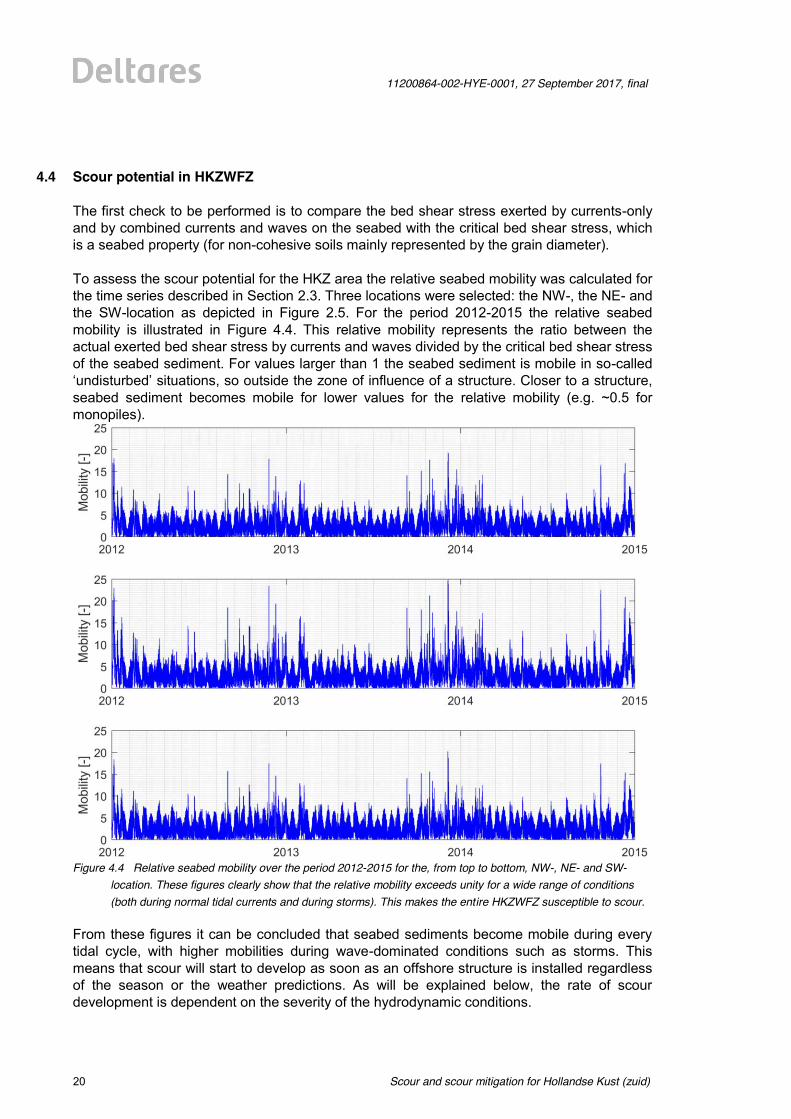
4.3 General description of local scour processes When a structure is installed in an offshore environment, the flow (combined action of currents and waves) will divert around the structure. A schematic overview is presented in Figure 4.3 for monopile foundations. Due to flow contraction the flow velocity will increase. To provide a rough estimate: according to the ‘simplified’ potential flow theory, the flow velocity can double close to the sides of the pile. Besides flow contraction, also different turbulent structures (vortices) will develop. Due to the vertical velocity gradient in the approach flow, a pressure gradient will develop at the upstream side of the pile. Because the pressure is larger higher up in the water column, a down flow will develop. When this down flow hits the seabed, it spirals off around both sides of the pile. The vortex that develops has the shape of a horseshoe and is therefore named “horseshoe vortex”. This vortex is the main driver of the scour process around a cylindrical pile. It typically extends up to one pile diameter from the pile. At the downstream side of the pile, alternating vortices will develop when the flow is shed off the pile. These vortices have a vertical axis and are named lee-wake vortices. Although the mean flow velocities at the leeside of the pile are close to zero, the velocity and pressure fluctuations can still be significant.
Figure 4.3 Flow pattern of a current flowing around a cylindrical pile (Sumer and Fredsøe, 2002); (upper left) a
scour hole in a scale model test with a (transparent) monopile. Because of the increased flow velocities and turbulent vortices, the bed shear stresses increase around the foundation. As a consequence the sediment transport capacity increases and local erosion (scour) will develop. In principle, both wave-dominated conditions (e.g. during storms) and current-dominated conditions (during ‘normal’ tidal conditions without significant waves) can cause scour development. However, for most structure shapes (monopiles, jackets, GBS) current-only or current-dominated conditions will create the deepest scour holes, while wave-dominated conditions will partially backfill the scour holes. This can be explained by the fact that the imbalance between sediment transport close and far away from the foundation will be much larger under current conditions, because the horseshoe vortex can hardly develop under oscillating wave conditions. The time-varying development of the scour depth will be further demonstrated for monopiles in Section 4.5. More information on the hydrodynamics and the mechanics of scour can be found in Sumer and Fredsøe (2002, 2006).
Scour and scour mitigation for Hollandse Kust (zuid)
11200864-002-HYE-0001, 27 September 2017, final
20 of 64
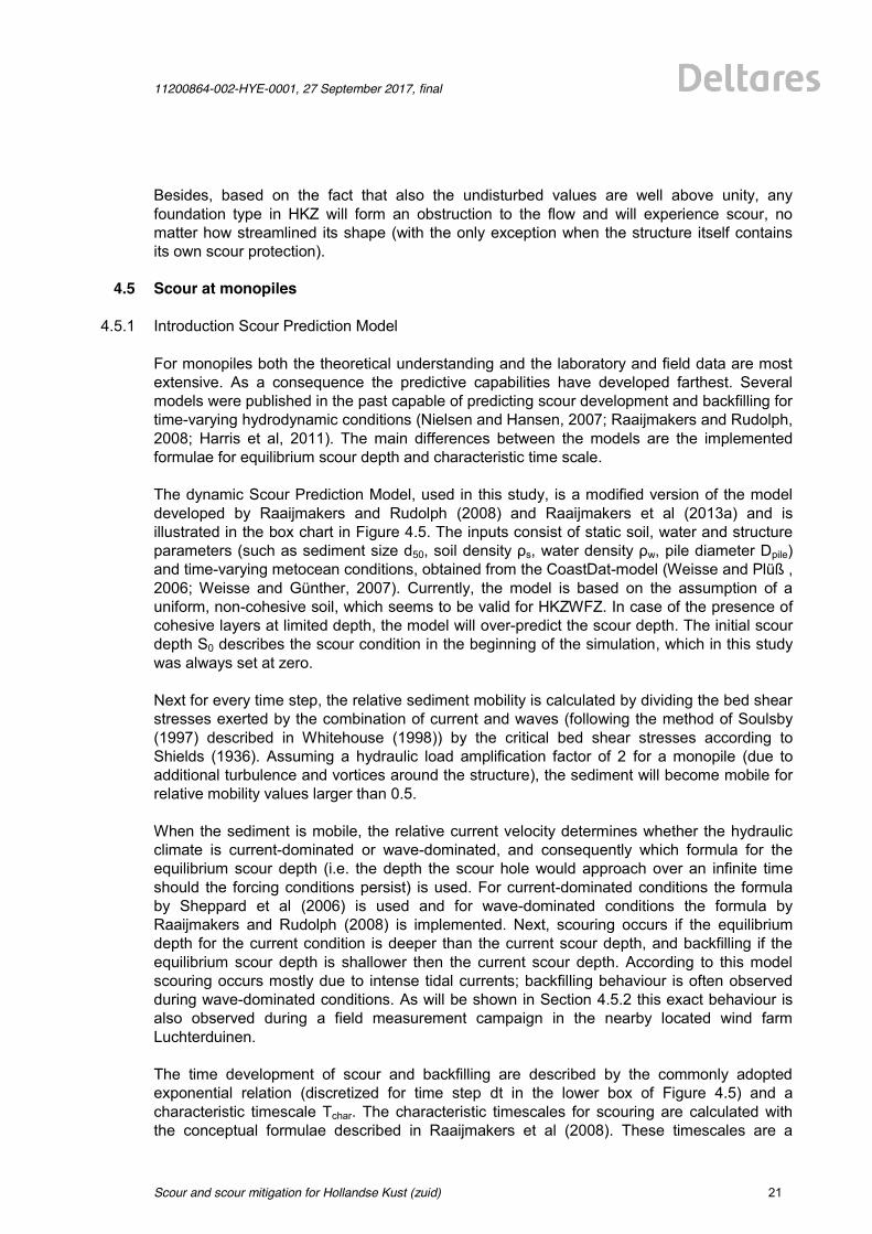
4.4 Scour potential in HKZWFZ The first check to be performed is to compare the bed shear stress exerted by currents-only and by combined currents and waves on the seabed with the critical bed shear stress, which is a seabed property (for non-cohesive soils mainly represented by the grain diameter). To assess the scour potential for the HKZ area the relative seabed mobility was calculated for the time series described in Section 2.3. Three locations were selected: the NW-, the NE- and the SW-location as depicted in Figure 2.5. For the period 2012-2015 the relative seabed mobility is illustrated in Figure 4.4. This relative mobility represents the ratio between the actual exerted bed shear stress by currents and waves divided by the critical bed shear stress of the seabed sediment. For values larger than 1 the seabed sediment is mobile in so-called ‘undisturbed’ situations, so outside the zone of influence of a structure. Closer to a structure, seabed sediment becomes mobile for lower values for the relative mobility (e.g. ~0.5 for monopiles).
Figure 4.4 Relative seabed mobility over the period 2012-2015 for the, from top to bottom, NW-, NE- and SW-
location. These figures clearly show that the relative mobility exceeds unity for a wide range of conditions (both during normal tidal currents and during storms). This makes the entire HKZWFZ susceptible to scour.
From these figures it can be concluded that seabed sediments become mobile during every tidal cycle, with higher mobilities during wave-dominated conditions such as storms. This means that scour will start to develop as soon as an offshore structure is installed regardless of the season or the weather predictions. As will be explained below, the rate of scour development is dependent on the severity of the hydrodynamic conditions.
11200864-002-HYE-0001, 27 September 2017, final
Scour and scour mitigation for Hollandse Kust (zuid)
21 of 64
Besides, based on the fact that also the undisturbed values are well above unity, any foundation type in HKZ will form an obstruction to the flow and will experience scour, no matter how streamlined its shape (with the only exception when the structure itself contains its own scour protection).
4.5 Scour at monopiles
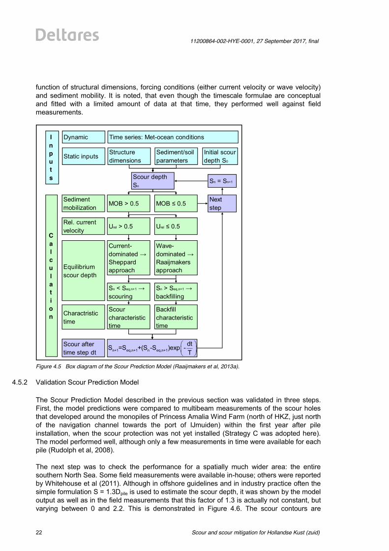
4.5.1 Introduction Scour Prediction Model For monopiles both the theoretical understanding and the laboratory and field data are most extensive. As a consequence the predictive capabilities have developed farthest. Several models were published in the past capable of predicting scour development and backfilling for time-varying hydrodynamic conditions (Nielsen and Hansen, 2007; Raaijmakers and Rudolph, 2008; Harris et al, 2011). The main differences between the models are the implemented formulae for equilibrium scour depth and characteristic time scale. The dynamic Scour Prediction Model, used in this study, is a modified version of the model developed by Raaijmakers and Rudolph (2008) and Raaijmakers et al (2013a) and is illustrated in the box chart in Figure 4.5. The inputs consist of static soil, water and structure parameters (such as sediment size d50, soil density ρs, water density ρw, pile diameter Dpile) and time-varying metocean conditions, obtained from the CoastDat-model (Weisse and Plüß , 2006; Weisse and Günther, 2007). Currently, the model is based on the assumption of a uniform, non-cohesive soil, which seems to be valid for HKZWFZ. In case of the presence of cohesive layers at limited depth, the model will over-predict the scour depth. The initial scour depth S0 describes the scour condition in the beginning of the simulation, which in this study was always set at zero. Next for every time step, the relative sediment mobility is calculated by dividing the bed shear stresses exerted by the combination of current and waves (following the method of Soulsby (1997) described in Whitehouse (1998)) by the critical bed shear stresses according to Shields (1936). Assuming a hydraulic load amplification factor of 2 for a monopile (due to additional turbulence and vortices around the structure), the sediment will become mobile for relative mobility values larger than 0.5. When the sediment is mobile, the relative current velocity determines whether the hydraulic climate is current-dominated or wave-dominated, and consequently which formula for the equilibrium scour depth (i.e. the depth the scour hole would approach over an infinite time should the forcing conditions persist) is used. For current-dominated conditions the formula by Sheppard et al (2006) is used and for wave-dominated conditions the formula by Raaijmakers and Rudolph (2008) is implemented. Next, scouring occurs if the equilibrium depth for the current condition is deeper than the current scour depth, and backfilling if the equilibrium scour depth is shallower then the current scour depth. According to this model scouring occurs mostly due to intense tidal currents; backfilling behaviour is often observed during wave-dominated conditions. As will be shown in Section 4.5.2 this exact behaviour is also observed during a field measurement campaign in the nearby located wind farm Luchterduinen. The time development of scour and backfilling are described by the commonly adopted exponential relation (discretized for time step dt in the lower box of Figure 4.5) and a characteristic timescale Tchar. The characteristic timescales for scouring are calculated with the conceptual formulae described in Raaijmakers et al (2008). These timescales are a
Scour and scour mitigation for Hollandse Kust (zuid)
11200864-002-HYE-0001, 27 September 2017, final
22 of 64
function of structural dimensions, forcing conditions (either current velocity or wave velocity) and sediment mobility. It is noted, that even though the timescale formulae are conceptual and fitted with a limited amount of data at that time, they performed well against field measurements.
Figure 4.5 Box diagram of the Scour Prediction Model (Raaijmakers et al, 2013a).
4.5.2 Validation Scour Prediction Model
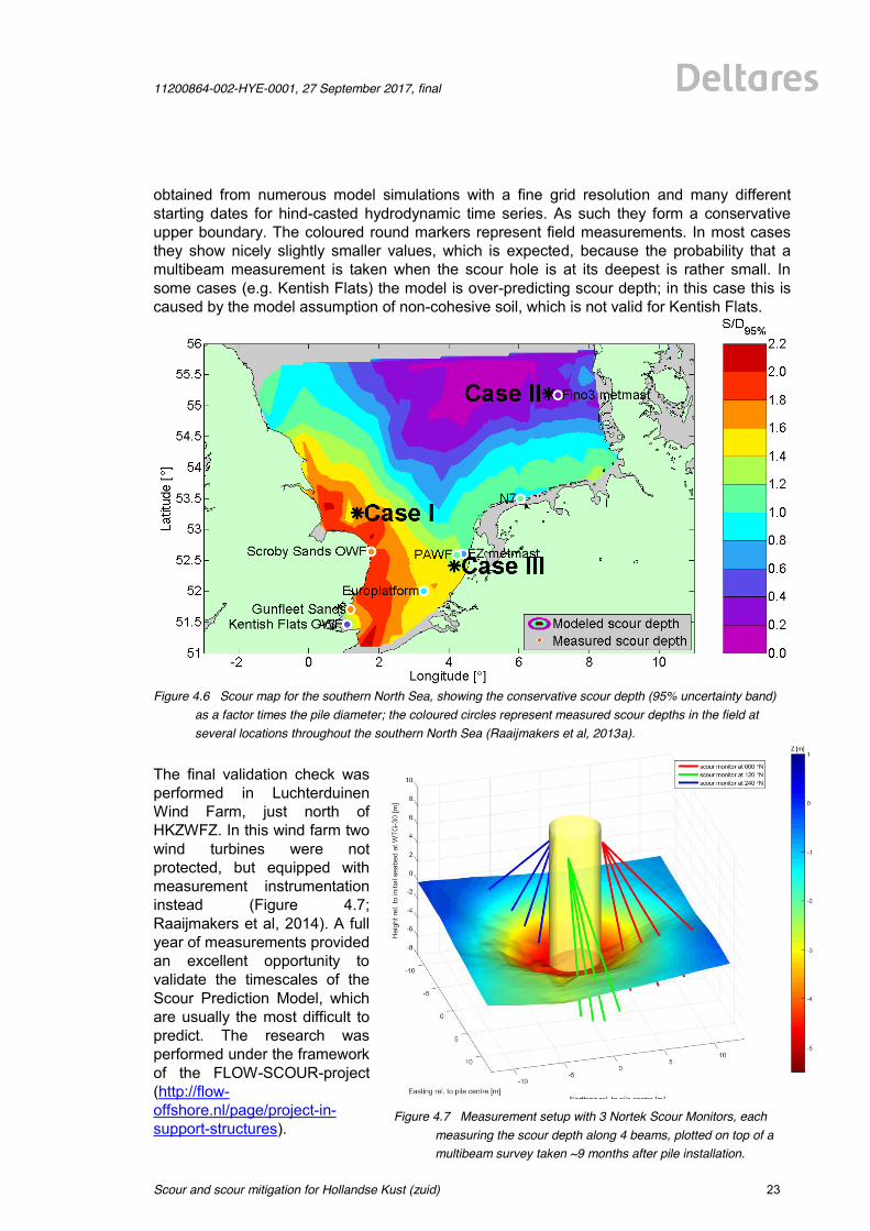
The Scour Prediction Model described in the previous section was validated in three steps. First, the model predictions were compared to multibeam measurements of the scour holes that developed around the monopiles of Princess Amalia Wind Farm (north of HKZ, just north of the navigation channel towards the port of IJmuiden) within the first year after pile installation, when the scour protection was not yet installed (Strategy C was adopted here). The model performed well, although only a few measurements in time were available for each pile (Rudolph et al, 2008). The next step was to check the performance for a spatially much wider area: the entire southern North Sea. Some field measurements were available in-house; others were reported by Whitehouse et al (2011). Although in offshore guidelines and in industry practice often the simple formulation S = 1.3Dpile is used to estimate the scour depth, it was shown by the model output as well as in the field measurements that this factor of 1.3 is actually not constant, but varying between 0 and 2.2. This is demonstrated in Figure 4.6. The scour contours are
Sediment mobilization
MOB > 0.5 MOB ≤ 0.5
Urel ≤ 0.5Urel > 0.5Rel. current velocity
Time series: Met-ocean conditions
Structure dimensions
Inputs
Dynamic
Static inputs Initial scour depth S0
Sediment/soil parameters
Next stepn = n + 1
Sn = Sn+1Scour depth Sn
Calculation
Wave-dominated → Raaijmakers approach
Current-dominated → Sheppard approachEquilibrium
scour depth
Sn < Seq,n+1 → scouring
Sn > Seq,n+1 → backfilling
Charactristic time
Scour characteristic time
Backfill characteristic time
Scour after time step dt
§ ·¨ ¸© ¹
n+1 eq,n+1 n eq,n+1dtS =S +(S -S )exp -T
11200864-002-HYE-0001, 27 September 2017, final
Scour and scour mitigation for Hollandse Kust (zuid)
23 of 64
obtained from numerous model simulations with a fine grid resolution and many different starting dates for hind-casted hydrodynamic time series. As such they form a conservative upper boundary. The coloured round markers represent field measurements. In most cases they show nicely slightly smaller values, which is expected, because the probability that a multibeam measurement is taken when the scour hole is at its deepest is rather small. In some cases (e.g. Kentish Flats) the model is over-predicting scour depth; in this case this is caused by the model assumption of non-cohesive soil, which is not valid for Kentish Flats.
Figure 4.6 Scour map for the southern North Sea, showing the conservative scour depth (95% uncertainty band)
as a factor times the pile diameter; the coloured circles represent measured scour depths in the field at several locations throughout the southern North Sea (Raaijmakers et al, 2013a).
The final validation check was performed in Luchterduinen Wind Farm, just north of HKZWFZ. In this wind farm two wind turbines were not protected, but equipped with measurement instrumentation instead (Figure 4.7; Raaijmakers et al, 2014). A full year of measurements provided an excellent opportunity to validate the timescales of the Scour Prediction Model, which are usually the most difficult to predict. The research was performed under the framework of the FLOW-SCOUR-project (http://flow-offshore.nl/page/project-in-support-structures).
Figure 4.7 Measurement setup with 3 Nortek Scour Monitors, each measuring the scour depth along 4 beams, plotted on top of a multibeam survey taken ~9 months after pile installation.
Scour and scour mitigation for Hollandse Kust (zuid)
11200864-002-HYE-0001, 27 September 2017, final
24 of 64
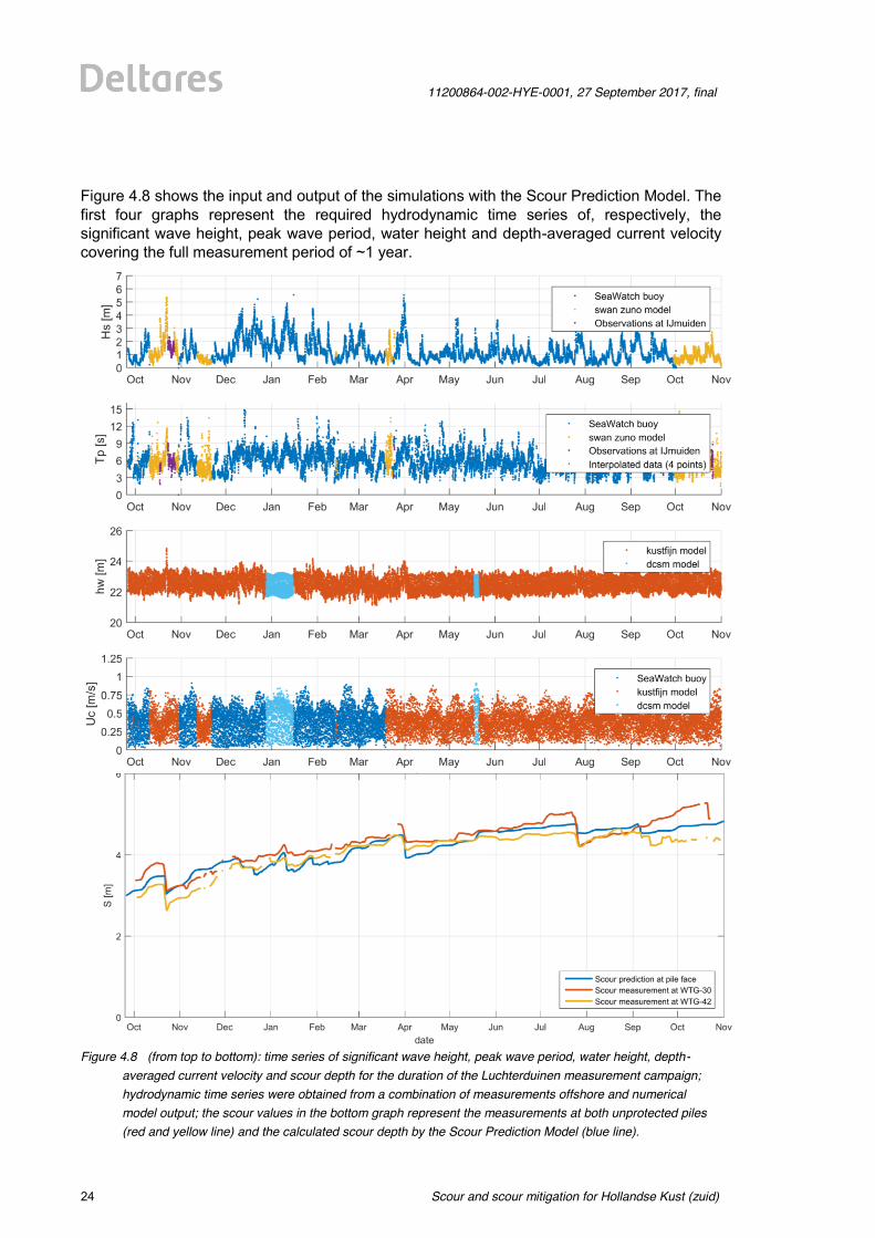
Figure 4.8 shows the input and output of the simulations with the Scour Prediction Model. The first four graphs represent the required hydrodynamic time series of, respectively, the significant wave height, peak wave period, water height and depth-averaged current velocity covering the full measurement period of ~1 year.
Figure 4.8 (from top to bottom): time series of significant wave height, peak wave period, water height, depth-
averaged current velocity and scour depth for the duration of the Luchterduinen measurement campaign; hydrodynamic time series were obtained from a combination of measurements offshore and numerical model output; the scour values in the bottom graph represent the measurements at both unprotected piles (red and yellow line) and the calculated scour depth by the Scour Prediction Model (blue line).
11200864-002-HYE-0001, 27 September 2017, final
Scour and scour mitigation for Hollandse Kust (zuid)
25 of 64
The hydrodynamics were re-constructed combining buoy measurements and numerical model hindcasts in order to obtain continuous time series. Note that the used wave buoys were buoys deployed at the time of construction of Luchterduinen wind farm and not the buoys that were later deployed in the HKZ area commissioned by RVO.nl. The bottom graph compares the field measurements of the scour depth with the model simulations. This figure shows that the model is capable of: • Predicting both the absolute values of the scour depth and the timescales of scour
development; • Distinguishing between current- and wave-dominated scour development, where in calm
wave conditions even the spring-neap tidal current patterns can be observed in both measurements and model output;
• Predicting values for backfilling during storm conditions similar to the measured values by the scour sensors;
Some other important findings during this Luchterduinen measurement campaign were (Raaijmakers et al, 2014): • Scour development until dynamic equilibrium takes about 1-1.5yr; • The scour pit reached a depth of about 5-5.5 m after one year (= 1.0-1.1*Dpile); • The final dynamic equilibrium depth is expected to stabilize around 6m = 1.2*Dpile (which
is according to design); • The diameter of the scour pit is about 5*Dpile and the side slopes are about 1:2 (1 m in
vertical direction against 2 m in horizontal direction); • The scour holes in Luchterduinen are very similar to the scour holes in laboratory tests
on scale ~1:40; this is very important because the scour formulae are all based on laboratory test results on small scale.
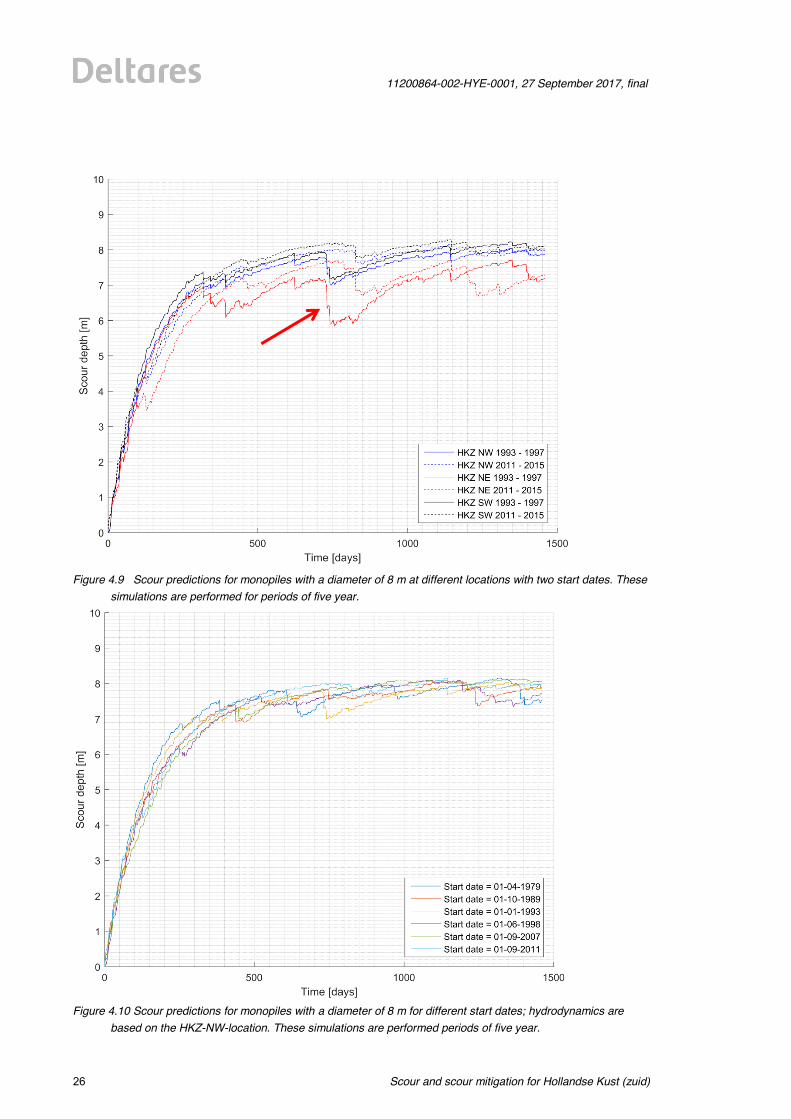
4.5.3 Scour predictions for HKZWFZ using Scour Prediction Model In order to provide quantitative scour predictions for HKZWFZ the Scour Prediction Model, as described in Section 4.5.1, is used to simulate scour development around monopiles by comparing different model input parameters such as monopile locations, pile diameters or start dates of hydrodynamic time series. In the previous section it was shown that this model is validated for the entire southern North Sea, but especially for the area around HKZ. Input for all comparisons with the Scour Prediction Model is gathered from the HKZ Metocean Database (DHI, 2017) as hydrodynamic time series. In this study the following three comparisons are made, with results discussed below Figure 4.11: • Varying monopile locations, following the locations defined in Section 2.1, and
assessing two start dates for periods of 5 years. By keeping the monopile diameter constant, here 8 m, the influence of local hydrodynamics such as current speed, wave height and water depth can be assessed. Results of these comparisons are depicted in Figure 4.9.
• Varying start dates of the hydrodynamic time series for one location, HKZ-NW, with durations of 5 year. By keeping the monopile location and diameter, here 8 m, constant and altering start dates of the time series, the influence of scour development starting in a summer or winter period is assessed. Results of this comparison are depicted in Figure 4.10.
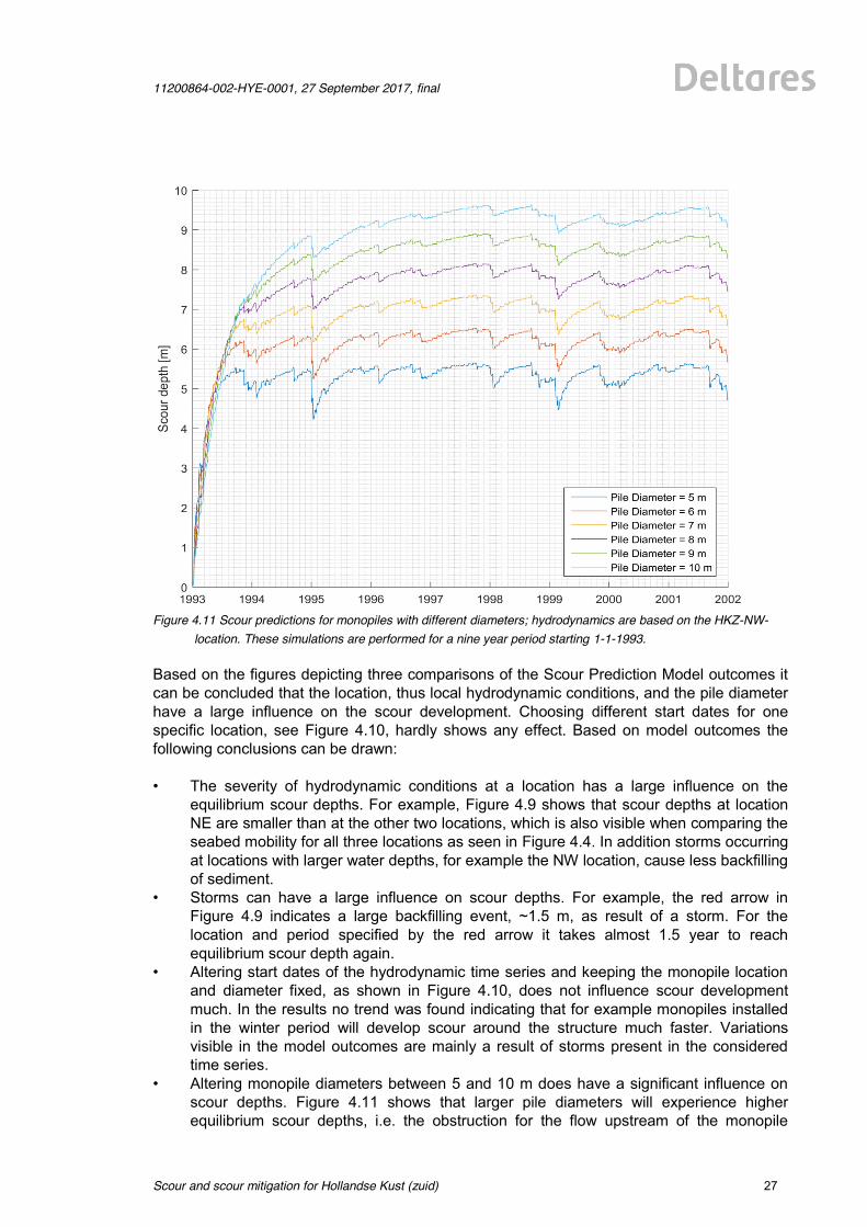
• Varying monopile diameters for one location, HKZ-NW, with simulations performed for a period of 9 year, starting at January 1st 1993. By keeping the location and start date fixed, the influence of the monopile diameter on scour development is assessed. Results of this comparison are depicted in Figure 4.11.
Scour and scour mitigation for Hollandse Kust (zuid)
11200864-002-HYE-0001, 27 September 2017, final
26 of 64
Figure 4.9 Scour predictions for monopiles with a diameter of 8 m at different locations with two start dates. These
simulations are performed for periods of five year.
Figure 4.10 Scour predictions for monopiles with a diameter of 8 m for different start dates; hydrodynamics are
based on the HKZ-NW-location. These simulations are performed periods of five year.
11200864-002-HYE-0001, 27 September 2017, final
Scour and scour mitigation for Hollandse Kust (zuid)
27 of 64
Figure 4.11 Scour predictions for monopiles with different diameters; hydrodynamics are based on the HKZ-NW-
location. These simulations are performed for a nine year period starting 1-1-1993. Based on the figures depicting three comparisons of the Scour Prediction Model outcomes it can be concluded that the location, thus local hydrodynamic conditions, and the pile diameter have a large influence on the scour development. Choosing different start dates for one specific location, see Figure 4.10, hardly shows any effect. Based on model outcomes the following conclusions can be drawn: • The severity of hydrodynamic conditions at a location has a large influence on the
equilibrium scour depths. For example, Figure 4.9 shows that scour depths at location NE are smaller than at the other two locations, which is also visible when comparing the seabed mobility for all three locations as seen in Figure 4.4. In addition storms occurring at locations with larger water depths, for example the NW location, cause less backfilling of sediment.
• Storms can have a large influence on scour depths. For example, the red arrow in Figure 4.9 indicates a large backfilling event, ~1.5 m, as result of a storm. For the location and period specified by the red arrow it takes almost 1.5 year to reach equilibrium scour depth again.
• Altering start dates of the hydrodynamic time series and keeping the monopile location and diameter fixed, as shown in Figure 4.10, does not influence scour development much. In the results no trend was found indicating that for example monopiles installed in the winter period will develop scour around the structure much faster. Variations visible in the model outcomes are mainly a result of storms present in the considered time series.
• Altering monopile diameters between 5 and 10 m does have a significant influence on scour depths. Figure 4.11 shows that larger pile diameters will experience higher equilibrium scour depths, i.e. the obstruction for the flow upstream of the monopile
Scour and scour mitigation for Hollandse Kust (zuid)
11200864-002-HYE-0001, 27 September 2017, final
28 of 64
increases, and have larger timescales, i.e. it takes longer to reach the (dynamic) equilibrium scour depth. It must however be noted that the ratio between the equilibrium scour depth and the pile diameter (Seq/Dpile) decreases from ~1.1 for a 5 m pile to ~0.95 for a 10 m pile.
In order to quantify outcomes of the Scour Prediction model, Table 4.1 gives an overview of the equilibrium scour depths for all comparisons both as an absolute number and as a ratio to the pile diameter. The varying start dates are not incorporated in the table since they hardly showed any influence on scour development. Note that the temporal effects of backfilling as a result of storm occurrences are not incorporated in the shown bandwidths.
Varying monopile diameter Varying monopile location Pile Diameter Seq/Dpile Seq Pile location Seq/Dpile Seq
5 m 1.00 – 1.15 5.0 – 6.0 m HKZ-NW (I) 0.90 – 1.05 7.2 – 8.4 m 6 m 0.95 – 1.10 5.7 – 6.6 m HKZ-NW (II) 0.90 – 1.05 7.2 – 8.4 m 7 m 0.95 – 1.10 6.6 – 7.7 m HKZ-NE (I) 0.90 – 1.00 7.2 – 8.0 m 8 m 0.90 – 1.05 7.2 – 8.4 m HKZ-NE (II) 0.90 – 1.00 7.2 – 8.0 m 9 m 0.90 – 1.00 8.1 – 9.0 m HKZ-SW (I) 0.95 – 1.10 7.6 – 8.8 m
10 m 0.90 – 1.00 9.0 – 10.0 m HKZ-SW (II) 0.95 – 1.10 7.6 – 8.8 m Table 4.1 Results of comparing different monopile diameters (left table) and different monopile locations (right
table) using the Scour Prediction Model. Values in this table are indicative best-estimates. For the pile locations, fourth column, the roman numbers I and II indicate the start dates of the two time series assessed per location. I indicates the period 1993 – 1997 and II indicates the period 2011 – 2015.
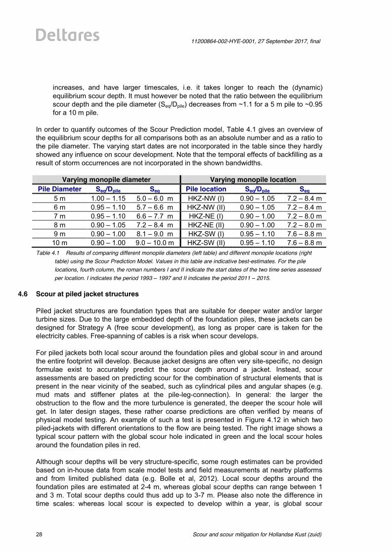
4.6 Scour at piled jacket structures Piled jacket structures are foundation types that are suitable for deeper water and/or larger turbine sizes. Due to the large embedded depth of the foundation piles, these jackets can be designed for Strategy A (free scour development), as long as proper care is taken for the electricity cables. Free-spanning of cables is a risk when scour develops. For piled jackets both local scour around the foundation piles and global scour in and around the entire footprint will develop. Because jacket designs are often very site-specific, no design formulae exist to accurately predict the scour depth around a jacket. Instead, scour assessments are based on predicting scour for the combination of structural elements that is present in the near vicinity of the seabed, such as cylindrical piles and angular shapes (e.g. mud mats and stiffener plates at the pile-leg-connection). In general: the larger the obstruction to the flow and the more turbulence is generated, the deeper the scour hole will get. In later design stages, these rather coarse predictions are often verified by means of physical model testing. An example of such a test is presented in Figure 4.12 in which two piled-jackets with different orientations to the flow are being tested. The right image shows a typical scour pattern with the global scour hole indicated in green and the local scour holes around the foundation piles in red. Although scour depths will be very structure-specific, some rough estimates can be provided based on in-house data from scale model tests and field measurements at nearby platforms and from limited published data (e.g. Bolle et al, 2012). Local scour depths around the foundation piles are estimated at 2-4 m, whereas global scour depths can range between 1 and 3 m. Total scour depths could thus add up to 3-7 m. Please also note the difference in time scales: whereas local scour is expected to develop within a year, is global scour
11200864-002-HYE-0001, 27 September 2017, final
Scour and scour mitigation for Hollandse Kust (zuid)
29 of 64
development a much longer process that can take many years, dependent on the occurrence of large storms, which typically enhance global scour development.
Figure 4.12 (Left) Example of scale model test in Atlantic Basin investigating scour development around jacket
foundations with two different orientations; (right) 3D-bathymetry after a scour test showing the global scour hole in green and the local scour holes in red.
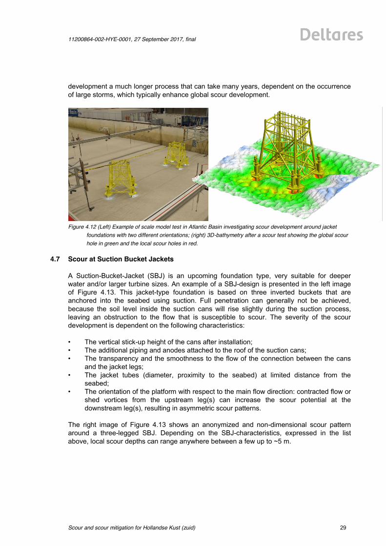
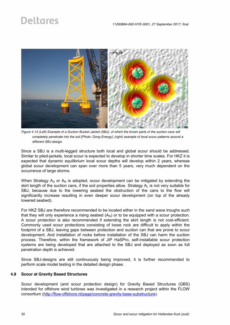
4.7 Scour at Suction Bucket Jackets A Suction-Bucket-Jacket (SBJ) is an upcoming foundation type, very suitable for deeper water and/or larger turbine sizes. An example of a SBJ-design is presented in the left image of Figure 4.13. This jacket-type foundation is based on three inverted buckets that are anchored into the seabed using suction. Full penetration can generally not be achieved, because the soil level inside the suction cans will rise slightly during the suction process, leaving an obstruction to the flow that is susceptible to scour. The severity of the scour development is dependent on the following characteristics: • The vertical stick-up height of the cans after installation; • The additional piping and anodes attached to the roof of the suction cans; • The transparency and the smoothness to the flow of the connection between the cans
and the jacket legs; • The jacket tubes (diameter, proximity to the seabed) at limited distance from the
seabed; • The orientation of the platform with respect to the main flow direction: contracted flow or
shed vortices from the upstream leg(s) can increase the scour potential at the downstream leg(s), resulting in asymmetric scour patterns.
The right image of Figure 4.13 shows an anonymized and non-dimensional scour pattern around a three-legged SBJ. Depending on the SBJ-characteristics, expressed in the list above, local scour depths can range anywhere between a few up to ~5 m.
Scour and scour mitigation for Hollandse Kust (zuid)
11200864-002-HYE-0001, 27 September 2017, final
30 of 64
Figure 4.13 (Left) Example of a Suction Bucket Jacket (SBJ), of which the brown parts of the suction cans will
completely penetrate into the soil [Photo: Dong Energy]; (right) example of local scour patterns around a different SBJ-design.
Since a SBJ is a multi-legged structure both local and global scour should be addressed. Similar to piled-jackets, local scour is expected to develop in shorter time scales. For HKZ it is expected that dynamic equilibrium local scour depths will develop within 2 years, whereas global scour development can span over more than 5 years, very much dependent on the occurrence of large storms. When Strategy AS or AR is adopted, scour development can be mitigated by extending the skirt length of the suction cans, if the soil properties allow. Strategy AL is not very suitable for SBJ, because due to the lowering seabed the obstruction of the cans to the flow will significantly increase resulting in even deeper scour development (on top of the already lowered seabed). For HKZ SBJ are therefore recommended to be located either in the sand wave troughs such that they will only experience a rising seabed (AR) or to be equipped with a scour protection. A scour protection is also recommended if extending the skirt length is not cost-efficient. Commonly used scour protections consisting of loose rock are difficult to apply within the footprint of a SBJ, leaving gaps between protection and suction can that are prone to scour development. And installation of rocks before installation of the SBJ can harm the suction process. Therefore, within the framework of JIP HaSPro, self-installable scour protection systems are being developed that are attached to the SBJ and deployed as soon as full penetration depth is achieved. Since SBJ-designs are still continuously being improved, it is further recommended to perform scale model testing in the detailed design phase.
4.8 Scour at Gravity Based Structures Scour development (and scour protection design) for Gravity Based Structures (GBS) intended for offshore wind turbines was investigated in a research project within the FLOW consortium (http://flow-offshore.nl/page/concrete-gravity-base-substructure).
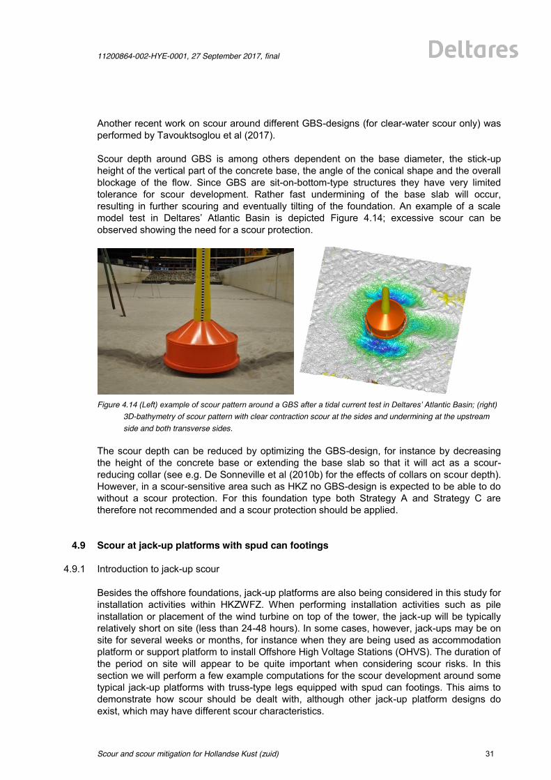
11200864-002-HYE-0001, 27 September 2017, final
Scour and scour mitigation for Hollandse Kust (zuid)
31 of 64
Another recent work on scour around different GBS-designs (for clear-water scour only) was performed by Tavouktsoglou et al (2017). Scour depth around GBS is among others dependent on the base diameter, the stick-up height of the vertical part of the concrete base, the angle of the conical shape and the overall blockage of the flow. Since GBS are sit-on-bottom-type structures they have very limited tolerance for scour development. Rather fast undermining of the base slab will occur, resulting in further scouring and eventually tilting of the foundation. An example of a scale model test in Deltares’ Atlantic Basin is depicted Figure 4.14; excessive scour can be observed showing the need for a scour protection.
Figure 4.14 (Left) example of scour pattern around a GBS after a tidal current test in Deltares’ Atlantic Basin; (right)
3D-bathymetry of scour pattern with clear contraction scour at the sides and undermining at the upstream side and both transverse sides.
The scour depth can be reduced by optimizing the GBS-design, for instance by decreasing the height of the concrete base or extending the base slab so that it will act as a scour-reducing collar (see e.g. De Sonneville et al (2010b) for the effects of collars on scour depth). However, in a scour-sensitive area such as HKZ no GBS-design is expected to be able to do without a scour protection. For this foundation type both Strategy A and Strategy C are therefore not recommended and a scour protection should be applied.
4.9 Scour at jack-up platforms with spud can footings
4.9.1 Introduction to jack-up scour Besides the offshore foundations, jack-up platforms are also being considered in this study for installation activities within HKZWFZ. When performing installation activities such as pile installation or placement of the wind turbine on top of the tower, the jack-up will be typically relatively short on site (less than 24-48 hours). In some cases, however, jack-ups may be on site for several weeks or months, for instance when they are being used as accommodation platform or support platform to install Offshore High Voltage Stations (OHVS). The duration of the period on site will appear to be quite important when considering scour risks. In this section we will perform a few example computations for the scour development around some typical jack-up platforms with truss-type legs equipped with spud can footings. This aims to demonstrate how scour should be dealt with, although other jack-up platform designs do exist, which may have different scour characteristics.
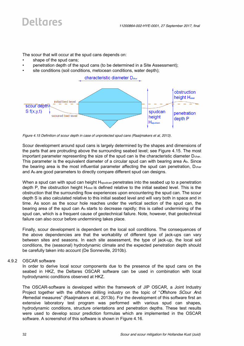
Scour and scour mitigation for Hollandse Kust (zuid)
11200864-002-HYE-0001, 27 September 2017, final
32 of 64
The scour that will occur at the spud cans depends on: • shape of the spud cans; • penetration depth of the spud cans (to be determined in a Site Assessment); • site conditions (soil conditions, metocean conditions, water depth);
Figure 4.15 Definition of scour depth in case of unprotected spud cans (Raaijmakers et al, 2013). Scour development around spud cans is largely determined by the shapes and dimensions of the parts that are protruding above the surrounding seabed level; see Figure 4.15. The most important parameter representing the size of the spud can is the characteristic diameter Dchar. This parameter is the equivalent diameter of a circular spud can with bearing area Ab. Since the bearing area is the most influential parameter affecting the spud can penetration, Dchar
and Ab are good parameters to directly compare different spud can designs. When a spud can with spud can height Hspudcan penetrates into the seabed up to a penetration depth P, the obstruction height Hobst is defined relative to the initial seabed level. This is the obstruction that the surrounding flow experiences upon encountering the spud can. The scour depth S is also calculated relative to this initial seabed level and will vary both in space and in time. As soon as the scour hole reaches under the vertical section of the spud can, the bearing area of the spud can Ab starts to decrease rapidly; this is called undermining of the spud can, which is a frequent cause of geotechnical failure. Note, however, that geotechnical failure can also occur before undermining takes place. Finally, scour development is dependent on the local soil conditions. The consequences of the above dependencies are that the workability of different type of jack-ups can vary between sites and seasons. In each site assessment, the type of jack-up, the local soil conditions, the (seasonal) hydrodynamic climate and the expected penetration depth should be carefully taken into account (De Sonneville, 2010b).
4.9.2 OSCAR software In order to derive local scour components due to the presence of the spud cans on the seabed in HKZ, the Deltares OSCAR software can be used in combination with local hydrodynamic conditions observed at HKZ. The OSCAR-software is developed within the framework of JIP OSCAR, a Joint Industry Project together with the offshore drilling industry on the topic of “Offshore SCour And Remedial measures” (Raaijmakers et al, 2013b). For the development of this software first an extensive laboratory test program was performed with various spud can shapes, hydrodynamic conditions, structure orientations and penetration depths. These test results were used to develop scour prediction formulas which are implemented in the OSCAR software. A screenshot of this software is shown in Figure 4.16.
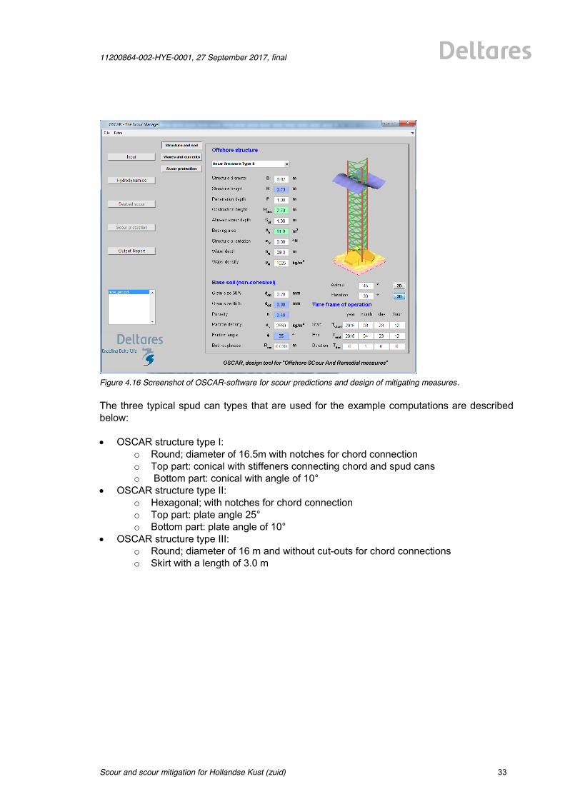
11200864-002-HYE-0001, 27 September 2017, final
Scour and scour mitigation for Hollandse Kust (zuid)
33 of 64
Figure 4.16 Screenshot of OSCAR-software for scour predictions and design of mitigating measures. The three typical spud can types that are used for the example computations are described below: x OSCAR structure type I:
o Round; diameter of 16.5m with notches for chord connection o Top part: conical with stiffeners connecting chord and spud cans o Bottom part: conical with angle of 10°
x OSCAR structure type II: o Hexagonal; with notches for chord connection o Top part: plate angle 25° o Bottom part: plate angle of 10°
x OSCAR structure type III: o Round; diameter of 16 m and without cut-outs for chord connections o Skirt with a length of 3.0 m
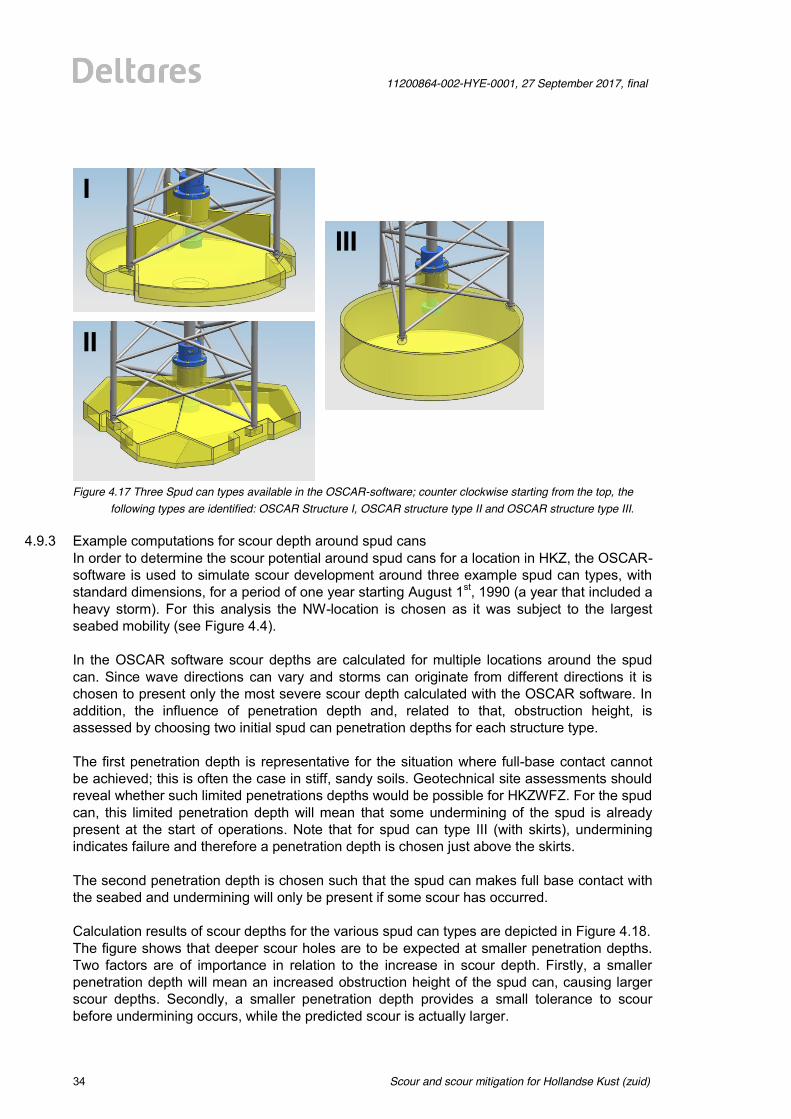
Scour and scour mitigation for Hollandse Kust (zuid)
11200864-002-HYE-0001, 27 September 2017, final
34 of 64
Figure 4.17 Three Spud can types available in the OSCAR-software; counter clockwise starting from the top, the
following types are identified: OSCAR Structure I, OSCAR structure type II and OSCAR structure type III.
4.9.3 Example computations for scour depth around spud cans In order to determine the scour potential around spud cans for a location in HKZ, the OSCAR-software is used to simulate scour development around three example spud can types, with standard dimensions, for a period of one year starting August 1st, 1990 (a year that included a heavy storm). For this analysis the NW-location is chosen as it was subject to the largest seabed mobility (see Figure 4.4). In the OSCAR software scour depths are calculated for multiple locations around the spud can. Since wave directions can vary and storms can originate from different directions it is chosen to present only the most severe scour depth calculated with the OSCAR software. In addition, the influence of penetration depth and, related to that, obstruction height, is assessed by choosing two initial spud can penetration depths for each structure type. The first penetration depth is representative for the situation where full-base contact cannot be achieved; this is often the case in stiff, sandy soils. Geotechnical site assessments should reveal whether such limited penetrations depths would be possible for HKZWFZ. For the spud can, this limited penetration depth will mean that some undermining of the spud is already present at the start of operations. Note that for spud can type III (with skirts), undermining indicates failure and therefore a penetration depth is chosen just above the skirts. The second penetration depth is chosen such that the spud can makes full base contact with the seabed and undermining will only be present if some scour has occurred. Calculation results of scour depths for the various spud can types are depicted in Figure 4.18. The figure shows that deeper scour holes are to be expected at smaller penetration depths. Two factors are of importance in relation to the increase in scour depth. Firstly, a smaller penetration depth will mean an increased obstruction height of the spud can, causing larger scour depths. Secondly, a smaller penetration depth provides a small tolerance to scour before undermining occurs, while the predicted scour is actually larger.
I
II
III
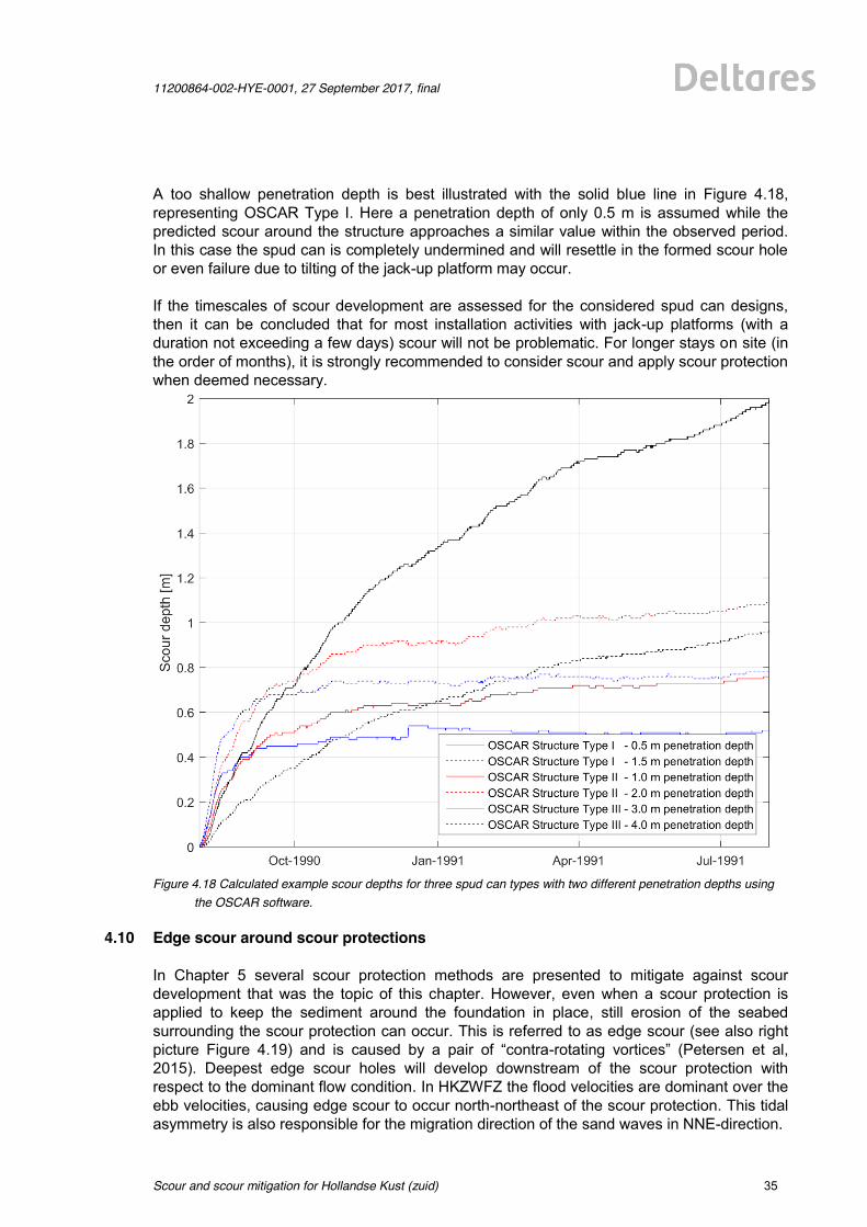
11200864-002-HYE-0001, 27 September 2017, final
Scour and scour mitigation for Hollandse Kust (zuid)
35 of 64
A too shallow penetration depth is best illustrated with the solid blue line in Figure 4.18, representing OSCAR Type I. Here a penetration depth of only 0.5 m is assumed while the predicted scour around the structure approaches a similar value within the observed period. In this case the spud can is completely undermined and will resettle in the formed scour hole or even failure due to tilting of the jack-up platform may occur. If the timescales of scour development are assessed for the considered spud can designs, then it can be concluded that for most installation activities with jack-up platforms (with a duration not exceeding a few days) scour will not be problematic. For longer stays on site (in the order of months), it is strongly recommended to consider scour and apply scour protection when deemed necessary.
Figure 4.18 Calculated example scour depths for three spud can types with two different penetration depths using
the OSCAR software.
4.10 Edge scour around scour protections In Chapter 5 several scour protection methods are presented to mitigate against scour development that was the topic of this chapter. However, even when a scour protection is applied to keep the sediment around the foundation in place, still erosion of the seabed surrounding the scour protection can occur. This is referred to as edge scour (see also right picture Figure 4.19) and is caused by a pair of “contra-rotating vortices” (Petersen et al, 2015). Deepest edge scour holes will develop downstream of the scour protection with respect to the dominant flow condition. In HKZWFZ the flood velocities are dominant over the ebb velocities, causing edge scour to occur north-northeast of the scour protection. This tidal asymmetry is also responsible for the migration direction of the sand waves in NNE-direction.
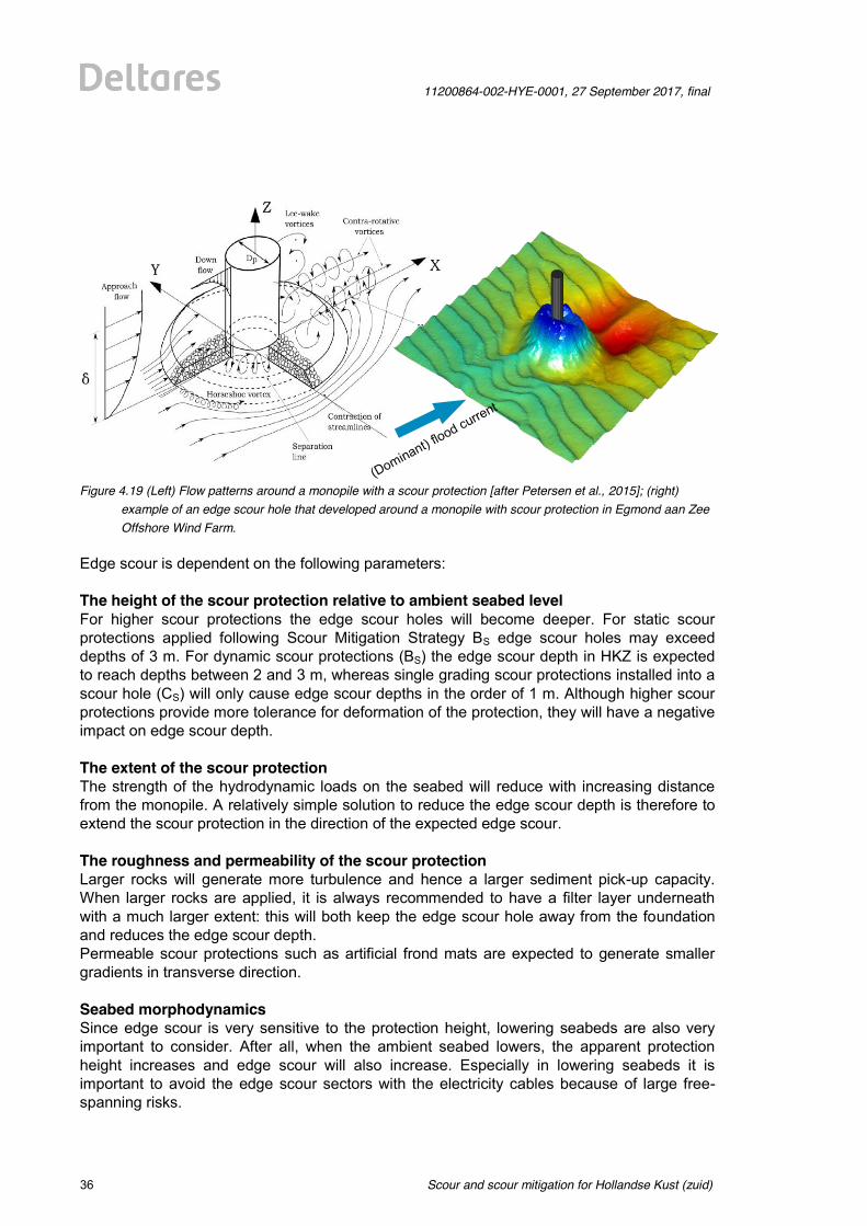
Scour and scour mitigation for Hollandse Kust (zuid)
11200864-002-HYE-0001, 27 September 2017, final
36 of 64
Figure 4.19 (Left) Flow patterns around a monopile with a scour protection [after Petersen et al., 2015]; (right)
example of an edge scour hole that developed around a monopile with scour protection in Egmond aan Zee Offshore Wind Farm.
Edge scour is dependent on the following parameters: The height of the scour protection relative to ambient seabed level For higher scour protections the edge scour holes will become deeper. For static scour protections applied following Scour Mitigation Strategy BS edge scour holes may exceed depths of 3 m. For dynamic scour protections (BS) the edge scour depth in HKZ is expected to reach depths between 2 and 3 m, whereas single grading scour protections installed into a scour hole (CS) will only cause edge scour depths in the order of 1 m. Although higher scour protections provide more tolerance for deformation of the protection, they will have a negative impact on edge scour depth. The extent of the scour protection The strength of the hydrodynamic loads on the seabed will reduce with increasing distance from the monopile. A relatively simple solution to reduce the edge scour depth is therefore to extend the scour protection in the direction of the expected edge scour. The roughness and permeability of the scour protection Larger rocks will generate more turbulence and hence a larger sediment pick-up capacity. When larger rocks are applied, it is always recommended to have a filter layer underneath with a much larger extent: this will both keep the edge scour hole away from the foundation and reduces the edge scour depth. Permeable scour protections such as artificial frond mats are expected to generate smaller gradients in transverse direction. Seabed morphodynamics Since edge scour is very sensitive to the protection height, lowering seabeds are also very important to consider. After all, when the ambient seabed lowers, the apparent protection height increases and edge scour will also increase. Especially in lowering seabeds it is important to avoid the edge scour sectors with the electricity cables because of large free-spanning risks.
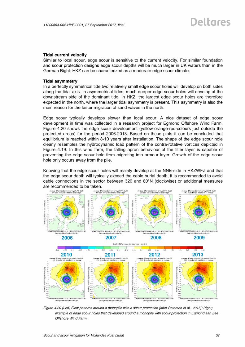
11200864-002-HYE-0001, 27 September 2017, final
Scour and scour mitigation for Hollandse Kust (zuid)
37 of 64
Tidal current velocity Similar to local scour, edge scour is sensitive to the current velocity. For similar foundation and scour protection designs edge scour depths will be much larger in UK waters than in the German Bight: HKZ can be characterized as a moderate edge scour climate. Tidal asymmetry In a perfectly symmetrical tide two relatively small edge scour holes will develop on both sides along the tidal axis. In asymmetrical tides, much deeper edge scour holes will develop at the downstream side of the dominant tide. In HKZ, the largest edge scour holes are therefore expected in the north, where the larger tidal asymmetry is present. This asymmetry is also the main reason for the faster migration of sand waves in the north. Edge scour typically develops slower than local scour. A nice dataset of edge scour development in time was collected in a research project for Egmond Offshore Wind Farm. Figure 4.20 shows the edge scour development (yellow-orange-red-colours just outside the protected areas) for the period 2006-2013. Based on these plots it can be concluded that equilibrium is reached within 8-10 years after installation. The shape of the edge scour hole clearly resembles the hydrodynamic load pattern of the contra-rotative vortices depicted in Figure 4.19. In this wind farm, the falling apron behaviour of the filter layer is capable of preventing the edge scour hole from migrating into armour layer. Growth of the edge scour hole only occurs away from the pile. Knowing that the edge scour holes will mainly develop at the NNE-side in HKZWFZ and that the edge scour depth will typically exceed the cable burial depth, it is recommended to avoid cable connections in the sector between 320 and 80°N (clockwise) or additional measures are recommended to be taken.
Figure 4.20 (Left) Flow patterns around a monopile with a scour protection [after Petersen et al., 2015]; (right)
example of edge scour holes that developed around a monopile with scour protection in Egmond aan Zee Offshore Wind Farm.
2006 2007 2008 2009
2010 2011 2012 2013
Scour and scour mitigation for Hollandse Kust (zuid)
11200864-002-HYE-0001, 27 September 2017, final
38 of 64
In conclusion: The smallest edge scour depths can be expected for foundations in the southern part of HKZ, in sand wave troughs, with Strategy BR or CR and scour protection methods with limited height and/or roughness (such as mattresses, gabions, artificial seaweed or dynamic scour protection with elongated filter layers in NNE-direction). Largest edge scour depths are to be expected for foundations in the northern part of HKZ, situated on sand wave crests, with Strategy BL and scour protection methods with a large height and/or roughness (large armour rocks or a large layer thickness of a single grading). Edge scour holes are expected to take about 5-10 years to reach their dynamic equilibrium depths.
11200864-002-HYE-0001, 27 September 2017, final
Scour and scour mitigation for Hollandse Kust (zuid)
39 of 64
5 Scour protection methods
5.1 Introduction When Scour Mitigation Strategy B or C is selected, then several scour protection methods can be applied to prevent scour around offshore foundations. This chapter presents first the design requirements for a proper scour protection (Section 5.2) and then provides a list of (other) criteria that can be used to weigh one method against the other (Section 5.3). Without knowing the scour mitigation strategy, the exact foundation locations, building schedules (e.g. in relation to required weather windows for the equipment used), preferred budget allocation in time (CAPEX vs OPEX: spending more during the construction phase or accepting higher maintenance costs), available construction equipment within the developing consortium etc., the optimum scour protection method cannot be selected. A detailed design will always be required in later design stages. An optimized scour protection design is often achieved by means of physical model testing. In the remaining sections of this chapter the most common protection methods, going from the most often applied scour protections consisting of loose rock (Sections 5.4 - 5.6) to alternative methods (Sections 5.7 - 5.14), are presented. For each scour protection method some advantages and points of attention are addressed without trying to be exhaustive. All presented values in this study should be considered as best-estimate values without any safety factors included; they should be verified in a later design stage. The choice for best-estimate values is based on the idea that the developers are most interested in realistic numbers at this stage without being too conservative. No rights can be derived from the presented values in this study, although utmost care was taken in compiling this study. Please note that on many of the presented scour methods extensive research including a large scale model test campaign is performed at present within the framework of Joint-Industry-Project HaSPro (JIP HaSPro). New design formulae and guidelines are being developed in this project by a large consortium of ~20 companies representing the entire value chain of the offshore wind industry.
5.2 Design requirements for a scour protection
Once it is decided that a scour protection is required, the designer has to choose between different scour protection methods. The most commonly applied scour protection method is a protection consisting of a few layers of rock. The knowledge level and field experience is most extensive for this method. However, many alternatives exist of which a selection is presented in this study. Regardless of the selected method, it should fulfil three technical requirements (see also Figure 5.1):
1 External stability 2 Internal stability 3 Flexibility
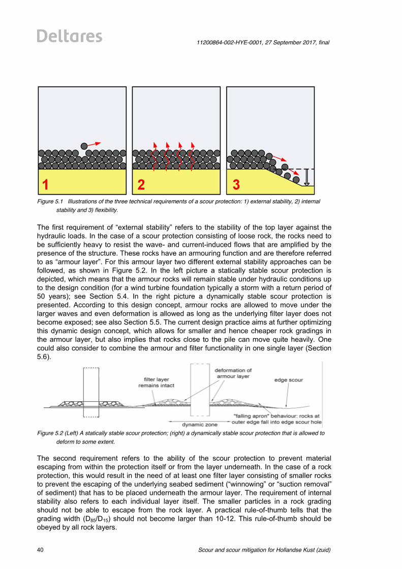
Scour and scour mitigation for Hollandse Kust (zuid)
11200864-002-HYE-0001, 27 September 2017, final
40 of 64
Figure 5.1 Illustrations of the three technical requirements of a scour protection: 1) external stability, 2) internal
stability and 3) flexibility.
The first requirement of “external stability” refers to the stability of the top layer against the hydraulic loads. In the case of a scour protection consisting of loose rock, the rocks need to be sufficiently heavy to resist the wave- and current-induced flows that are amplified by the presence of the structure. These rocks have an armouring function and are therefore referred to as “armour layer”. For this armour layer two different external stability approaches can be followed, as shown in Figure 5.2. In the left picture a statically stable scour protection is depicted, which means that the armour rocks will remain stable under hydraulic conditions up to the design condition (for a wind turbine foundation typically a storm with a return period of 50 years); see Section 5.4. In the right picture a dynamically stable scour protection is presented. According to this design concept, armour rocks are allowed to move under the larger waves and even deformation is allowed as long as the underlying filter layer does not become exposed; see also Section 5.5. The current design practice aims at further optimizing this dynamic design concept, which allows for smaller and hence cheaper rock gradings in the armour layer, but also implies that rocks close to the pile can move quite heavily. One could also consider to combine the armour and filter functionality in one single layer (Section 5.6).
Figure 5.2 (Left) A statically stable scour protection; (right) a dynamically stable scour protection that is allowed to
deform to some extent. The second requirement refers to the ability of the scour protection to prevent material escaping from within the protection itself or from the layer underneath. In the case of a rock protection, this would result in the need of at least one filter layer consisting of smaller rocks to prevent the escaping of the underlying seabed sediment (“winnowing” or “suction removal” of sediment) that has to be placed underneath the armour layer. The requirement of internal stability also refers to each individual layer itself. The smaller particles in a rock grading should not be able to escape from the rock layer. A practical rule-of-thumb tells that the grading width (D85/D15) should not become larger than 10-12. This rule-of-thumb should be obeyed by all rock layers.
11200864-002-HYE-0001, 27 September 2017, final
Scour and scour mitigation for Hollandse Kust (zuid)
41 of 64
The third requirement refers to flexibility. Erosion of the seabed surrounding the scour protection can still occur even when the seabed close to the structure is protected. This is referred to as edge scour (see also right picture in Figure 5.2) and it is caused by a pair of “contra-rotating vortices” that will develop downstream of the scour protection with respect to the dominant flow condition, as was explained in Section 4.9. Besides edge scour, seabed lowering may also be related to autonomous large-scale morphological processes (i.e. for HKZ due to migrating sand waves). The difference between both lowering processes is that whereas large-scale morphological processes cause a lowering all around the scour protection, edge scour is often focused in certain sectors. For both cases, the scour protection should be able to follow this seabed lowering at the edges by deforming without completely failing. For a rock protection this would result in filter rocks rolling down and protecting the side slope at the edges of the scour protection. This is referred to as “falling apron behaviour” (right image in Figure 5.2). The commonly applied solution for rock protections to obey the flexibility-criterion is to increase the extent of the filter layer to allow for some sacrifice of filter rocks to a falling apron. Note that the increase in extent to counteract edge scour may be limited to certain sectors, resulting in elliptical shapes of the filter layer.
5.3 Evaluation criteria for selection of scour protection method Without knowledge on selected foundation type, exact location, contractor’s offshore equipment and utilities preferences with respect to balancing CAPEX vs. OPEX, the optimum scour protection method cannot be determined in this study. Instead a (non-exhaustive) list of criteria that can be used by the developer when selecting a scour protection method is presented. In this study the scour protection methods are not scored quantitatively on these criteria, because these scores will dependent on many unknown variables at this stage. Some remarks, however, will be made at each individual scour protection method. The following (non-exhaustive) list of criteria can be used to evaluate protection methods: 1. Hydraulic stability (external and internal)
The most obvious criterion, because the scour protection should at least be able to survive the hydrodynamic loads. We refer both to design storm loads (wave-dominated conditions) as well as milder normal conditions (often current-dominated) that might gradually change the shape of the surrounding seabed, leading to different hydrodynamic load patterns on the protection.
2. Robustness / Durability (lifetime in marine environment) How robust and durable is the mitigating measure for the design lifetime?
3. Installability Is the mitigating measure easily installable or is dedicated equipment required? Can the protection be installed after installation of the foundation? Even after cable installation? Or after scour has developed (in case of Strategy C)?
4. Survivability of events that are more severe than the design event Scour protections for wind turbine foundations are in most cases designed for a storm event with a return period of 50 years; scour protections for an Offshore High Voltage Station for a storm event with a return period of 100 years. But what will happen in case of a more extreme event: will there be any resilience in the system? If not, should a safety factor be considered?
Scour and scour mitigation for Hollandse Kust (zuid)
11200864-002-HYE-0001, 27 September 2017, final
42 of 64
5. Cost (qualitative) How cost-efficient is this method relative to the other mitigating measures? Will the costs mainly be made in the construction phase (CAPEX) or is regular maintenance expected (OPEX)?
6. Interaction with seabed morphology (flexibility) Is this method effective in preventing a further decrease of the bed level in case of a lowering seabed (Strategy BL and CL)?
7. Interaction with cable protection Does the scour protection method have to provide safety to the electricity cable against dropped and dragged objects or is the cable equipped with its own protection system?
8. Tailor-made solutions (customizability / adaptability) Does this mitigating method allow for tailor-made layouts, adapting to difficult structural shapes, steep seabed slopes and/or complex areas where a lot of cables are connected?
9. Environmental impact Are the used materials environmentally friendly? Or will the mitigating measures even increase the biodiversity in the wind parks as a positive side effect?
10. Side effects (unwanted) The presence of mitigating measures can cause flow disturbance in itself, resulting in edge scour development as an unwanted side effect. In general, the smoother and flatter a mitigating measure is, the smaller the side effects. Mitigating measures that create smoother gradients in sediment transport to the surrounding seabed also are effective in reducing edge scour.
11. Monitoring Is it possible to properly monitor the scour protection? Could something happen to the seabed below the scour protection without being able to observe this? In general smaller elements (loose rock, bags) will always have a connection with the underlying seafloor. Larger elements like mattresses, geotubes and rock-filled mesh bags can have gaps underneath and in between that are difficult to monitor.
12. Effects on decommissioning Is it possible to remove the mitigating measures when the wind park has to be decommissioned? Is there a risk that un-natural elements will remain at the seafloor?
13. Proven method Is there a lot of experience with the mitigating measure and application in an offshore environment, preferably under similar conditions?
5.4 Static scour protection consisting of rock In a fully static scour protection, the armour rocks are designed such that they remain stable for hydraulic conditions up to the design condition. For the application around offshore wind foundations, such a static design requirement typically results in a very conservative and safe design with armour rock gradings in the order of 60-300 kg or larger. The use of large armour rock has several drawbacks. Due to the use of a large armour rock grading, it is well possible that more than two rock layers are required to fulfil the internal stability requirement. It also requires a larger total protection height resulting in an increased potential for edge scour and larger rock volumes. The rocks are also located higher in the water column and have a larger roughness compared to a design with a smaller armour grading. These two factors will increase the hydraulic load on the armour layer (see also Section 4.10). In case of large armour rocks it is typically not be possible to drive a monopile through the protection, meaning that the largest rock gradings cannot be installed before pile installation.
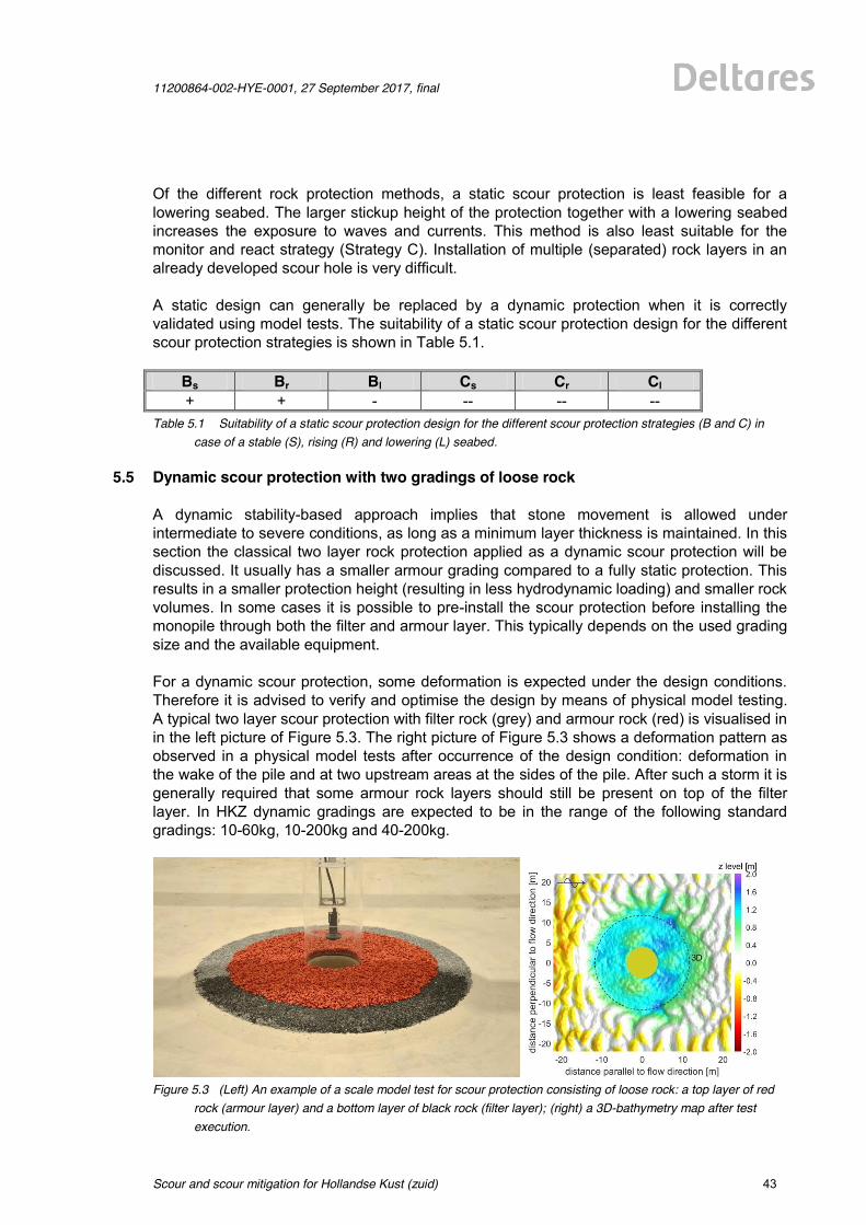
11200864-002-HYE-0001, 27 September 2017, final
Scour and scour mitigation for Hollandse Kust (zuid)
43 of 64
Of the different rock protection methods, a static scour protection is least feasible for a lowering seabed. The larger stickup height of the protection together with a lowering seabed increases the exposure to waves and currents. This method is also least suitable for the monitor and react strategy (Strategy C). Installation of multiple (separated) rock layers in an already developed scour hole is very difficult. A static design can generally be replaced by a dynamic protection when it is correctly validated using model tests. The suitability of a static scour protection design for the different scour protection strategies is shown in Table 5.1.
Bs Br Bl Cs Cr Cl + + - -- -- --
Table 5.1 Suitability of a static scour protection design for the different scour protection strategies (B and C) in case of a stable (S), rising (R) and lowering (L) seabed.
5.5 Dynamic scour protection with two gradings of loose rock A dynamic stability-based approach implies that stone movement is allowed under intermediate to severe conditions, as long as a minimum layer thickness is maintained. In this section the classical two layer rock protection applied as a dynamic scour protection will be discussed. It usually has a smaller armour grading compared to a fully static protection. This results in a smaller protection height (resulting in less hydrodynamic loading) and smaller rock volumes. In some cases it is possible to pre-install the scour protection before installing the monopile through both the filter and armour layer. This typically depends on the used grading size and the available equipment. For a dynamic scour protection, some deformation is expected under the design conditions. Therefore it is advised to verify and optimise the design by means of physical model testing. A typical two layer scour protection with filter rock (grey) and armour rock (red) is visualised in in the left picture of Figure 5.3. The right picture of Figure 5.3 shows a deformation pattern as observed in a physical model tests after occurrence of the design condition: deformation in the wake of the pile and at two upstream areas at the sides of the pile. After such a storm it is generally required that some armour rock layers should still be present on top of the filter layer. In HKZ dynamic gradings are expected to be in the range of the following standard gradings: 10-60kg, 10-200kg and 40-200kg.
Figure 5.3 (Left) An example of a scale model test for scour protection consisting of loose rock: a top layer of red
rock (armour layer) and a bottom layer of black rock (filter layer); (right) a 3D-bathymetry map after test execution.
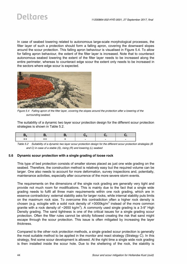
Scour and scour mitigation for Hollandse Kust (zuid)
11200864-002-HYE-0001, 27 September 2017, final
44 of 64
In case of seabed lowering related to autonomous large-scale morphological processes, the filter layer of such a protection should form a falling apron, covering the downward slopes around the scour protection. This falling apron behaviour is visualised in Figure 5.4. To allow for falling apron behaviour, the extent of the filter layer is increased. Note that to counteract autonomous seabed lowering the extent of the filter layer needs to be increased along the entire perimeter, whereas to counteract edge scour the extent only needs to be increased in the sectors where edge scour is expected.
Figure 5.4 Falling apron of the filter layer, covering the slopes around the protection after a lowering of the
surrounding seabed. The suitability of a dynamic two layer scour protection design for the different scour protection strategies is shown in Table 5.2.
Bs Br Bl Cs Cr Cl ++ ++ + - - -
Table 5.2 Suitability of a dynamic two layer scour protection design for the different scour protection strategies (B and C) in case of a stable (S), rising (R) and lowering (L) seabed
5.6 Dynamic scour protection with a single grading of loose rock This type of bed protection consists of smaller stones placed as just one wide grading on the seabed. Therefore, the construction method is relatively easy but the required volume can be larger. One also needs to account for more deformation, survey inspections and, potentially, maintenance activities, especially after occurrence of the more severe storm events. The requirements on the dimensions of the single rock grading are generally very tight and provide not much room for modifications. This is mainly due to the fact that a single wide grading needs to fulfil all three main requirements within one rock grading, which are in essence contradictory: external stability asks for larger rocks, while internal stability puts limits on the maximum rock size. To overcome this contradiction often a higher rock density is chosen (e.g. eclogite with a solid rock density of >3000kg/m3 instead of the more common granite with a rock density of ~2650 kg/m3). A commonly used single grading is a 3-9” High Density grading. The sand tightness is one of the critical issues for a single grading scour protection. Often the filter rules cannot be strictly followed creating the risk that sand might escape through the scour protection. This issue is often mitigated by increasing the layer thickness. Compared to the other rock protection methods, a single graded scour protection is generally the most suitable method to be applied in the monitor and react strategy (Strategy C). In this strategy, first some scour development is allowed. At the right time a single wide rock grading is then installed inside the scour hole. Due to the sheltering of the rock, the stability is
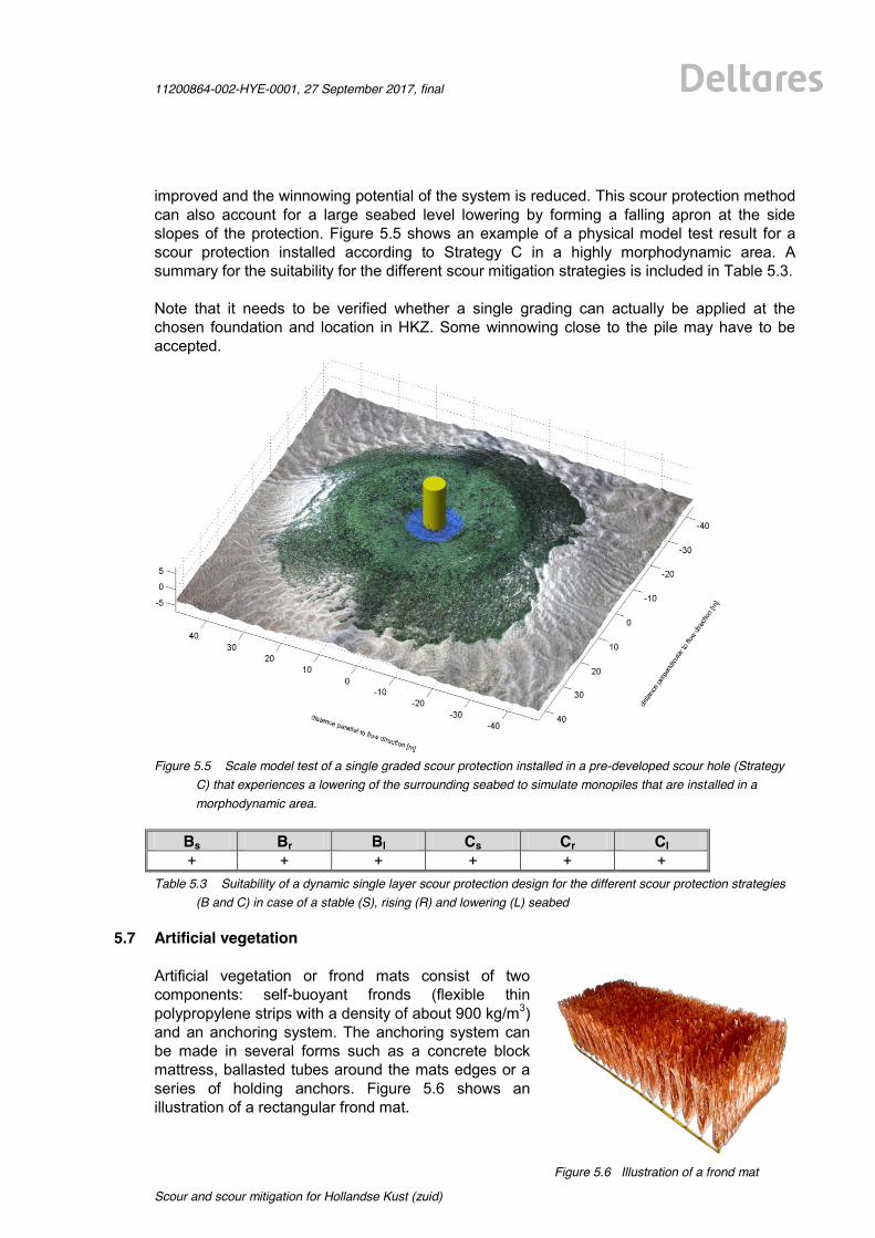
11200864-002-HYE-0001, 27 September 2017, final
Scour and scour mitigation for Hollandse Kust (zuid)
45 of 64
improved and the winnowing potential of the system is reduced. This scour protection method can also account for a large seabed level lowering by forming a falling apron at the side slopes of the protection. Figure 5.5 shows an example of a physical model test result for a scour protection installed according to Strategy C in a highly morphodynamic area. A summary for the suitability for the different scour mitigation strategies is included in Table 5.3. Note that it needs to be verified whether a single grading can actually be applied at the chosen foundation and location in HKZ. Some winnowing close to the pile may have to be accepted.
Figure 5.5 Scale model test of a single graded scour protection installed in a pre-developed scour hole (Strategy
C) that experiences a lowering of the surrounding seabed to simulate monopiles that are installed in a morphodynamic area.
Bs Br Bl Cs Cr Cl + + + + + +
Table 5.3 Suitability of a dynamic single layer scour protection design for the different scour protection strategies (B and C) in case of a stable (S), rising (R) and lowering (L) seabed
5.7 Artificial vegetation Artificial vegetation or frond mats consist of two components: self-buoyant fronds (flexible thin polypropylene strips with a density of about 900 kg/m3) and an anchoring system. The anchoring system can be made in several forms such as a concrete block mattress, ballasted tubes around the mats edges or a series of holding anchors. Figure 5.6 shows an illustration of a rectangular frond mat.
Figure 5.6 Illustration of a frond mat
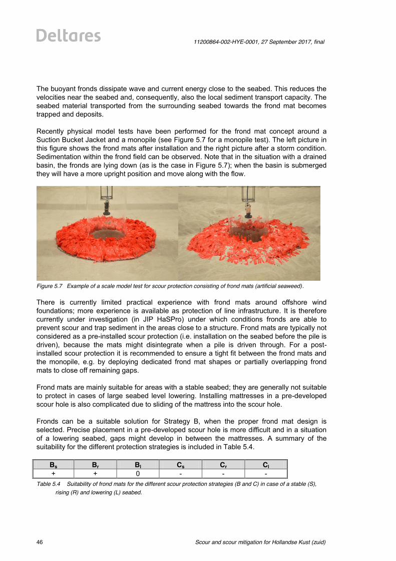
Scour and scour mitigation for Hollandse Kust (zuid)
11200864-002-HYE-0001, 27 September 2017, final
46 of 64
The buoyant fronds dissipate wave and current energy close to the seabed. This reduces the velocities near the seabed and, consequently, also the local sediment transport capacity. The seabed material transported from the surrounding seabed towards the frond mat becomes trapped and deposits. Recently physical model tests have been performed for the frond mat concept around a Suction Bucket Jacket and a monopile (see Figure 5.7 for a monopile test). The left picture in this figure shows the frond mats after installation and the right picture after a storm condition. Sedimentation within the frond field can be observed. Note that in the situation with a drained basin, the fronds are lying down (as is the case in Figure 5.7); when the basin is submerged they will have a more upright position and move along with the flow.
Figure 5.7 Example of a scale model test for scour protection consisting of frond mats (artificial seaweed). There is currently limited practical experience with frond mats around offshore wind foundations; more experience is available as protection of line infrastructure. It is therefore currently under investigation (in JIP HaSPro) under which conditions fronds are able to prevent scour and trap sediment in the areas close to a structure. Frond mats are typically not considered as a pre-installed scour protection (i.e. installation on the seabed before the pile is driven), because the mats might disintegrate when a pile is driven through. For a post-installed scour protection it is recommended to ensure a tight fit between the frond mats and the monopile, e.g. by deploying dedicated frond mat shapes or partially overlapping frond mats to close off remaining gaps. Frond mats are mainly suitable for areas with a stable seabed; they are generally not suitable to protect in cases of large seabed level lowering. Installing mattresses in a pre-developed scour hole is also complicated due to sliding of the mattress into the scour hole. Fronds can be a suitable solution for Strategy B, when the proper frond mat design is selected. Precise placement in a pre-developed scour hole is more difficult and in a situation of a lowering seabed, gaps might develop in between the mattresses. A summary of the suitability for the different protection strategies is included in Table 5.4.
Bs Br Bl Cs Cr Cl + + 0 - - -
Table 5.4 Suitability of frond mats for the different scour protection strategies (B and C) in case of a stable (S), rising (R) and lowering (L) seabed.
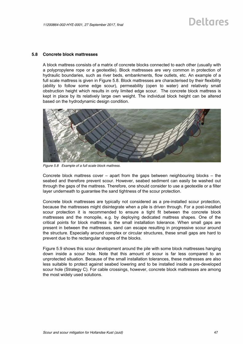
11200864-002-HYE-0001, 27 September 2017, final
Scour and scour mitigation for Hollandse Kust (zuid)
47 of 64
5.8 Concrete block mattresses A block mattress consists of a matrix of concrete blocks connected to each other (usually with a polypropylene rope or a geotextile). Block mattresses are very common in protection of hydraulic boundaries, such as river beds, embankments, flow outlets, etc. An example of a full scale mattress is given in Figure 5.8. Block mattresses are characterised by their flexibility (ability to follow some edge scour), permeability (open to water) and relatively small obstruction height which results in only limited edge scour. The concrete block mattress is kept in place by its relatively large own weight. The individual block height can be altered based on the hydrodynamic design condition.
Figure 5.8 Example of a full scale block mattress. Concrete block mattress cover – apart from the gaps between neighbouring blocks – the seabed and therefore prevent scour. However, seabed sediment can easily be washed out through the gaps of the mattress. Therefore, one should consider to use a geotextile or a filter layer underneath to guarantee the sand tightness of the scour protection. Concrete block mattresses are typically not considered as a pre-installed scour protection, because the mattresses might disintegrate when a pile is driven through. For a post-installed scour protection it is recommended to ensure a tight fit between the concrete block mattresses and the monopile, e.g. by deploying dedicated mattress shapes. One of the critical points for block mattress is the small installation tolerance. When small gaps are present in between the mattresses, sand can escape resulting in progressive scour around the structure. Especially around complex or circular structures, these small gaps are hard to prevent due to the rectangular shapes of the blocks. Figure 5.9 shows this scour development around the pile with some block mattresses hanging down inside a scour hole. Note that this amount of scour is far less compared to an unprotected situation. Because of the small installation tolerances, these mattresses are also less suitable to protect against seabed lowering and to be installed inside a pre-developed scour hole (Strategy C). For cable crossings, however, concrete block mattresses are among the most widely used solutions.
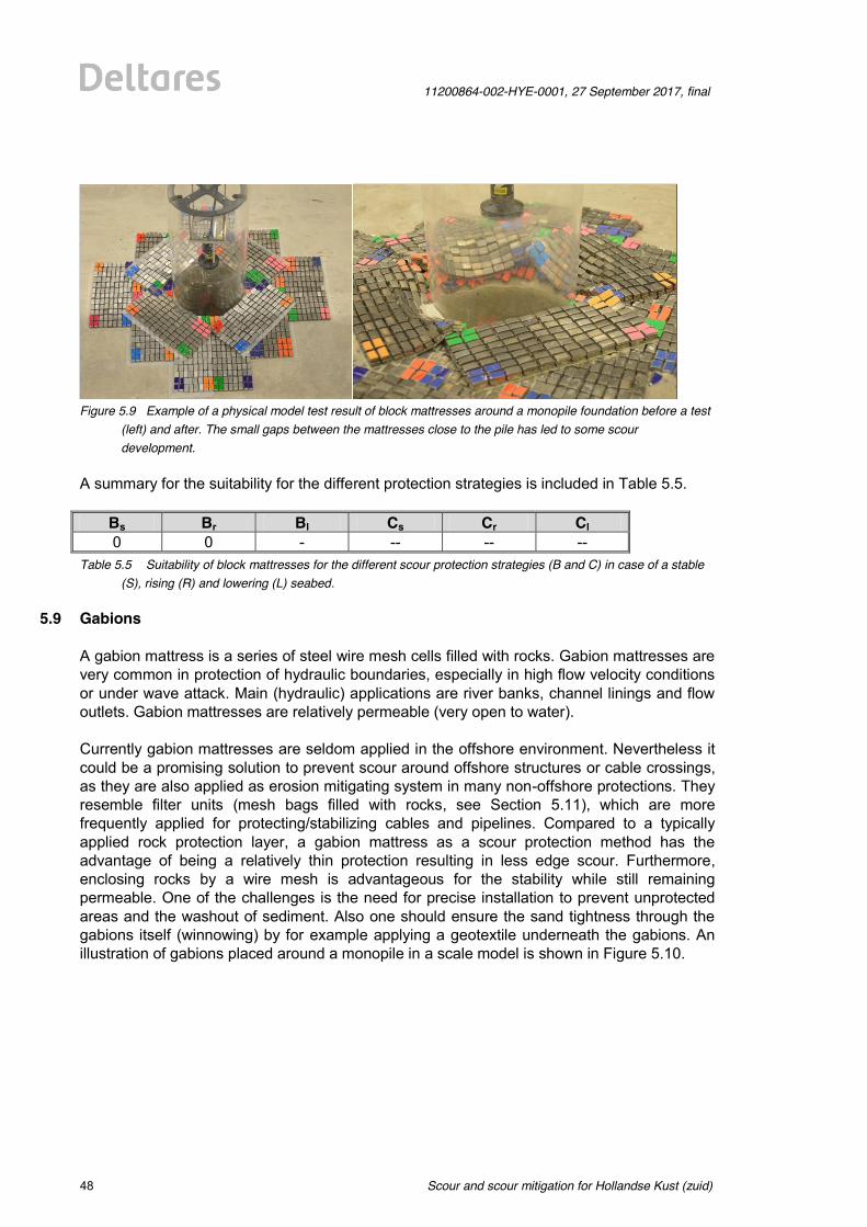
Scour and scour mitigation for Hollandse Kust (zuid)
11200864-002-HYE-0001, 27 September 2017, final
48 of 64
Figure 5.9 Example of a physical model test result of block mattresses around a monopile foundation before a test
(left) and after. The small gaps between the mattresses close to the pile has led to some scour development.
A summary for the suitability for the different protection strategies is included in Table 5.5.
Bs Br Bl Cs Cr Cl 0 0 - -- -- --
Table 5.5 Suitability of block mattresses for the different scour protection strategies (B and C) in case of a stable (S), rising (R) and lowering (L) seabed.
5.9 Gabions A gabion mattress is a series of steel wire mesh cells filled with rocks. Gabion mattresses are very common in protection of hydraulic boundaries, especially in high flow velocity conditions or under wave attack. Main (hydraulic) applications are river banks, channel linings and flow outlets. Gabion mattresses are relatively permeable (very open to water). Currently gabion mattresses are seldom applied in the offshore environment. Nevertheless it could be a promising solution to prevent scour around offshore structures or cable crossings, as they are also applied as erosion mitigating system in many non-offshore protections. They resemble filter units (mesh bags filled with rocks, see Section 5.11), which are more frequently applied for protecting/stabilizing cables and pipelines. Compared to a typically applied rock protection layer, a gabion mattress as a scour protection method has the advantage of being a relatively thin protection resulting in less edge scour. Furthermore, enclosing rocks by a wire mesh is advantageous for the stability while still remaining permeable. One of the challenges is the need for precise installation to prevent unprotected areas and the washout of sediment. Also one should ensure the sand tightness through the gabions itself (winnowing) by for example applying a geotextile underneath the gabions. An illustration of gabions placed around a monopile in a scale model is shown in Figure 5.10.
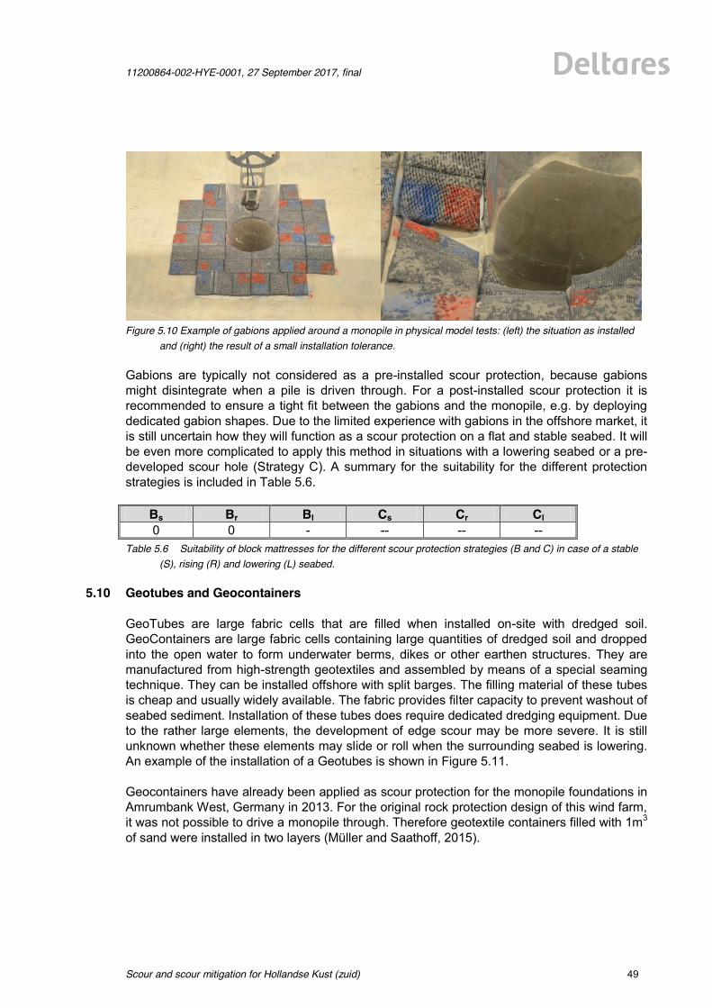
11200864-002-HYE-0001, 27 September 2017, final
Scour and scour mitigation for Hollandse Kust (zuid)
49 of 64
Figure 5.10 Example of gabions applied around a monopile in physical model tests: (left) the situation as installed
and (right) the result of a small installation tolerance. Gabions are typically not considered as a pre-installed scour protection, because gabions might disintegrate when a pile is driven through. For a post-installed scour protection it is recommended to ensure a tight fit between the gabions and the monopile, e.g. by deploying dedicated gabion shapes. Due to the limited experience with gabions in the offshore market, it is still uncertain how they will function as a scour protection on a flat and stable seabed. It will be even more complicated to apply this method in situations with a lowering seabed or a pre-developed scour hole (Strategy C). A summary for the suitability for the different protection strategies is included in Table 5.6.
Bs Br Bl Cs Cr Cl 0 0 - -- -- --
Table 5.6 Suitability of block mattresses for the different scour protection strategies (B and C) in case of a stable (S), rising (R) and lowering (L) seabed.
5.10 Geotubes and Geocontainers GeoTubes are large fabric cells that are filled when installed on-site with dredged soil. GeoContainers are large fabric cells containing large quantities of dredged soil and dropped into the open water to form underwater berms, dikes or other earthen structures. They are manufactured from high-strength geotextiles and assembled by means of a special seaming technique. They can be installed offshore with split barges. The filling material of these tubes is cheap and usually widely available. The fabric provides filter capacity to prevent washout of seabed sediment. Installation of these tubes does require dedicated dredging equipment. Due to the rather large elements, the development of edge scour may be more severe. It is still unknown whether these elements may slide or roll when the surrounding seabed is lowering. An example of the installation of a Geotubes is shown in Figure 5.11. Geocontainers have already been applied as scour protection for the monopile foundations in Amrumbank West, Germany in 2013. For the original rock protection design of this wind farm, it was not possible to drive a monopile through. Therefore geotextile containers filled with 1m3 of sand were installed in two layers (Müller and Saathoff, 2015).
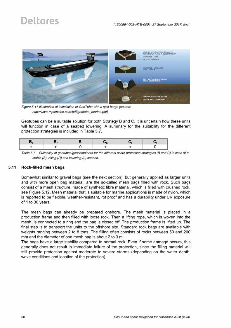
Scour and scour mitigation for Hollandse Kust (zuid)
11200864-002-HYE-0001, 27 September 2017, final
50 of 64
Figure 5.11 Illustration of installation of GeoTube with a split barge [source:
http://www.mpsmaine.com/pdf/geotube_marine.pdf]. Geotubes can be a suitable solution for both Strategy B and C. It is uncertain how these units will function in case of a seabed lowering. A summary for the suitability for the different protection strategies is included in Table 5.7.
Bs Br Bl Cs Cr Cl + + 0 + + 0
Table 5.7 Suitability of geotubes/geocontainers for the different scour protection strategies (B and C) in case of a stable (S), rising (R) and lowering (L) seabed.
5.11 Rock-filled mesh bags Somewhat similar to gravel bags (see the next section), but generally applied as larger units and with more open bag material, are the so-called mesh bags filled with rock. Such bags consist of a mesh structure, made of synthetic fibre material, which is filled with crushed rock, see Figure 5.12. Mesh material that is suitable for marine applications is made of nylon, which is reported to be flexible, weather-resistant, rot proof and has a durability under UV exposure of 1 to 30 years. The mesh bags can already be prepared onshore. The mesh material is placed in a production frame and then filled with loose rock. Then a lifting rope, which is woven into the mesh, is connected to a ring and the bag is closed off. The production frame is lifted up. The final step is to transport the units to the offshore site. Standard rock bags are available with weights ranging between 2 to 8 tons. The filling often consists of rocks between 50 and 200 mm and the diameter of one mesh bag is about 2 to 3 m. The bags have a large stability compared to normal rock. Even if some damage occurs, this generally does not result in immediate failure of the protection, since the filling material will still provide protection against moderate to severe storms (depending on the water depth, wave conditions and location of the protection).
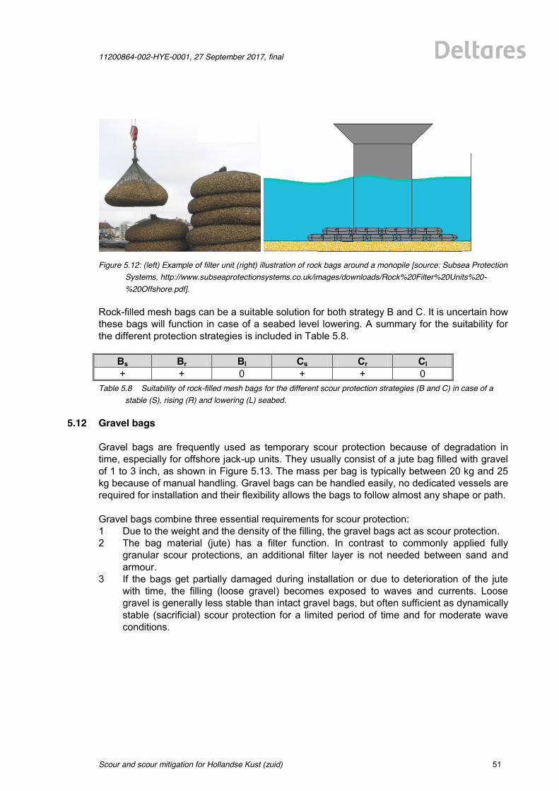
11200864-002-HYE-0001, 27 September 2017, final
Scour and scour mitigation for Hollandse Kust (zuid)
51 of 64
Figure 5.12: (left) Example of filter unit (right) illustration of rock bags around a monopile [source: Subsea Protection
Systems, http://www.subseaprotectionsystems.co.uk/images/downloads/Rock%20Filter%20Units%20-%20Offshore.pdf].
Rock-filled mesh bags can be a suitable solution for both strategy B and C. It is uncertain how these bags will function in case of a seabed level lowering. A summary for the suitability for the different protection strategies is included in Table 5.8.
Bs Br Bl Cs Cr Cl + + 0 + + 0
Table 5.8 Suitability of rock-filled mesh bags for the different scour protection strategies (B and C) in case of a stable (S), rising (R) and lowering (L) seabed.
5.12 Gravel bags
Gravel bags are frequently used as temporary scour protection because of degradation in time, especially for offshore jack-up units. They usually consist of a jute bag filled with gravel of 1 to 3 inch, as shown in Figure 5.13. The mass per bag is typically between 20 kg and 25 kg because of manual handling. Gravel bags can be handled easily, no dedicated vessels are required for installation and their flexibility allows the bags to follow almost any shape or path. Gravel bags combine three essential requirements for scour protection: 1 Due to the weight and the density of the filling, the gravel bags act as scour protection. 2 The bag material (jute) has a filter function. In contrast to commonly applied fully
granular scour protections, an additional filter layer is not needed between sand and armour.
3 If the bags get partially damaged during installation or due to deterioration of the jute with time, the filling (loose gravel) becomes exposed to waves and currents. Loose gravel is generally less stable than intact gravel bags, but often sufficient as dynamically stable (sacrificial) scour protection for a limited period of time and for moderate wave conditions.
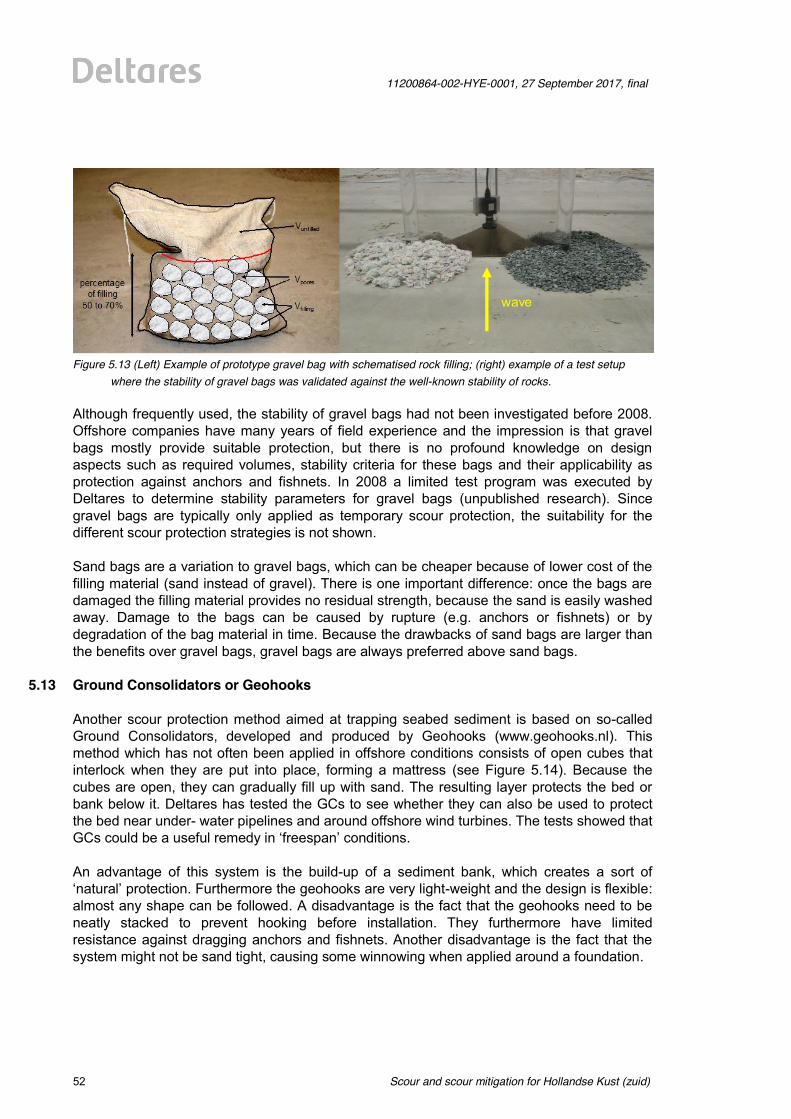
Scour and scour mitigation for Hollandse Kust (zuid)
11200864-002-HYE-0001, 27 September 2017, final
52 of 64
Figure 5.13 (Left) Example of prototype gravel bag with schematised rock filling; (right) example of a test setup
where the stability of gravel bags was validated against the well-known stability of rocks. Although frequently used, the stability of gravel bags had not been investigated before 2008. Offshore companies have many years of field experience and the impression is that gravel bags mostly provide suitable protection, but there is no profound knowledge on design aspects such as required volumes, stability criteria for these bags and their applicability as protection against anchors and fishnets. In 2008 a limited test program was executed by Deltares to determine stability parameters for gravel bags (unpublished research). Since gravel bags are typically only applied as temporary scour protection, the suitability for the different scour protection strategies is not shown. Sand bags are a variation to gravel bags, which can be cheaper because of lower cost of the filling material (sand instead of gravel). There is one important difference: once the bags are damaged the filling material provides no residual strength, because the sand is easily washed away. Damage to the bags can be caused by rupture (e.g. anchors or fishnets) or by degradation of the bag material in time. Because the drawbacks of sand bags are larger than the benefits over gravel bags, gravel bags are always preferred above sand bags.
5.13 Ground Consolidators or Geohooks Another scour protection method aimed at trapping seabed sediment is based on so-called Ground Consolidators, developed and produced by Geohooks (www.geohooks.nl). This method which has not often been applied in offshore conditions consists of open cubes that interlock when they are put into place, forming a mattress (see Figure 5.14). Because the cubes are open, they can gradually fill up with sand. The resulting layer protects the bed or bank below it. Deltares has tested the GCs to see whether they can also be used to protect the bed near under- water pipelines and around offshore wind turbines. The tests showed that GCs could be a useful remedy in ‘freespan’ conditions. An advantage of this system is the build-up of a sediment bank, which creates a sort of ‘natural’ protection. Furthermore the geohooks are very light-weight and the design is flexible: almost any shape can be followed. A disadvantage is the fact that the geohooks need to be neatly stacked to prevent hooking before installation. They furthermore have limited resistance against dragging anchors and fishnets. Another disadvantage is the fact that the system might not be sand tight, causing some winnowing when applied around a foundation.
wave

11200864-002-HYE-0001, 27 September 2017, final
Scour and scour mitigation for Hollandse Kust (zuid)
53 of 64
Figure 5.14 (Left) One Geohook; (right) a mattress constructed from Geohooks that was capable of trapping
sediment in a test with an exposed pipeline performed in Deltares’ Atlantic Basin. Geohooks are most suitable for Strategy C because the winnowing potential is reduced when the protection is installed in a more sheltered scour hole. For a flat seabed and in case of a potential lowering, the winnowing issue is considered to be larger making this method less applicable. A summary for the suitability for the different protection strategies is included in Table 5.9.
Bs Br Bl Cs Cr Cl 0 0 0 + + 0
Table 5.9 Suitability of Geohooks for the different scour protection strategies (B and C) in case of a stable (S), rising (R) and lowering (L) seabed; note that the application as cable crossing is much more straightforward.
5.14 Mattresses of rubber tyres Another scour protection method consists of (recycled) rubber tyres tied together in a mattress or combined in a net, see Figure 5.15. The theoretical background is still limited, but some good experiences have been reported from Scroby Sands (a wind park that is known for its long struggle against scour). The shape of the tyres is claimed by the manufacturer to be very effective in trapping sediment; for current-dominated conditions around foundations it still needs to be investigated whether sediment under the open tyres can be picked up by the horseshoe vortex. A disadvantage is the use of rubber in a marine environment. Rubber tyres are most suitable for Strategy C and less applicable on a flat seabed (because of winnowing potential) and in case of a potential lowering (for the same reasons as the geohooks). A summary for the suitability for the different protection strategies is included in Table 5.10.
Bs Br Bl Cs Cr Cl 0 0 0 + + 0
Table 5.10 Suitability of rubber tyres for the different scour protection strategies (B and C) in case of a stable (S), rising (R) and lowering (L) seabed.
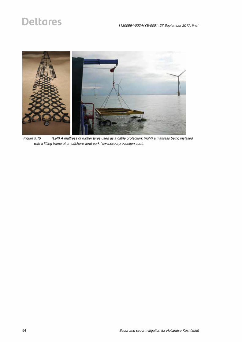
Scour and scour mitigation for Hollandse Kust (zuid)
11200864-002-HYE-0001, 27 September 2017, final
54 of 64
Figure 5.15 (Left) A mattress of rubber tyres used as a cable protection; (right) a mattress being installed
with a lifting frame at an offshore wind park (www.scourprevention.com).
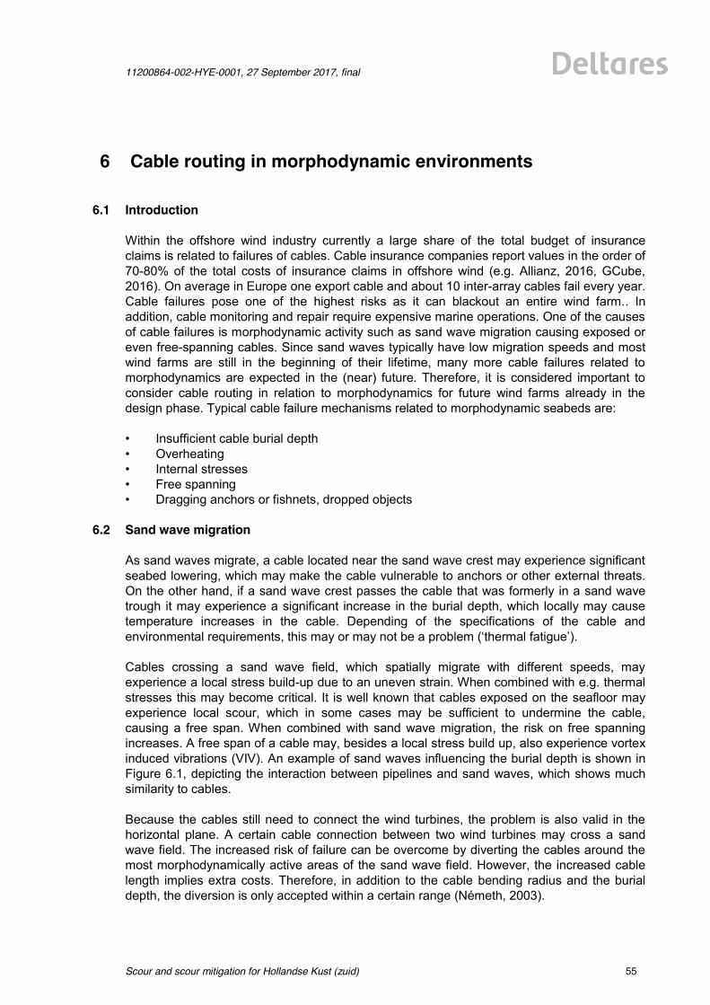
11200864-002-HYE-0001, 27 September 2017, final
Scour and scour mitigation for Hollandse Kust (zuid)
55 of 64
6 Cable routing in morphodynamic environments
6.1 Introduction Within the offshore wind industry currently a large share of the total budget of insurance claims is related to failures of cables. Cable insurance companies report values in the order of 70-80% of the total costs of insurance claims in offshore wind (e.g. Allianz, 2016, GCube, 2016). On average in Europe one export cable and about 10 inter-array cables fail every year. Cable failures pose one of the highest risks as it can blackout an entire wind farm.. In addition, cable monitoring and repair require expensive marine operations. One of the causes of cable failures is morphodynamic activity such as sand wave migration causing exposed or even free-spanning cables. Since sand waves typically have low migration speeds and most wind farms are still in the beginning of their lifetime, many more cable failures related to morphodynamics are expected in the (near) future. Therefore, it is considered important to consider cable routing in relation to morphodynamics for future wind farms already in the design phase. Typical cable failure mechanisms related to morphodynamic seabeds are: • Insufficient cable burial depth • Overheating • Internal stresses • Free spanning • Dragging anchors or fishnets, dropped objects
6.2 Sand wave migration As sand waves migrate, a cable located near the sand wave crest may experience significant seabed lowering, which may make the cable vulnerable to anchors or other external threats. On the other hand, if a sand wave crest passes the cable that was formerly in a sand wave trough it may experience a significant increase in the burial depth, which locally may cause temperature increases in the cable. Depending of the specifications of the cable and environmental requirements, this may or may not be a problem (‘thermal fatigue’). Cables crossing a sand wave field, which spatially migrate with different speeds, may experience a local stress build-up due to an uneven strain. When combined with e.g. thermal stresses this may become critical. It is well known that cables exposed on the seafloor may experience local scour, which in some cases may be sufficient to undermine the cable, causing a free span. When combined with sand wave migration, the risk on free spanning increases. A free span of a cable may, besides a local stress build up, also experience vortex induced vibrations (VIV). An example of sand waves influencing the burial depth is shown in Figure 6.1, depicting the interaction between pipelines and sand waves, which shows much similarity to cables. Because the cables still need to connect the wind turbines, the problem is also valid in the horizontal plane. A certain cable connection between two wind turbines may cross a sand wave field. The increased risk of failure can be overcome by diverting the cables around the most morphodynamically active areas of the sand wave field. However, the increased cable length implies extra costs. Therefore, in addition to the cable bending radius and the burial depth, the diversion is only accepted within a certain range (Németh, 2003).
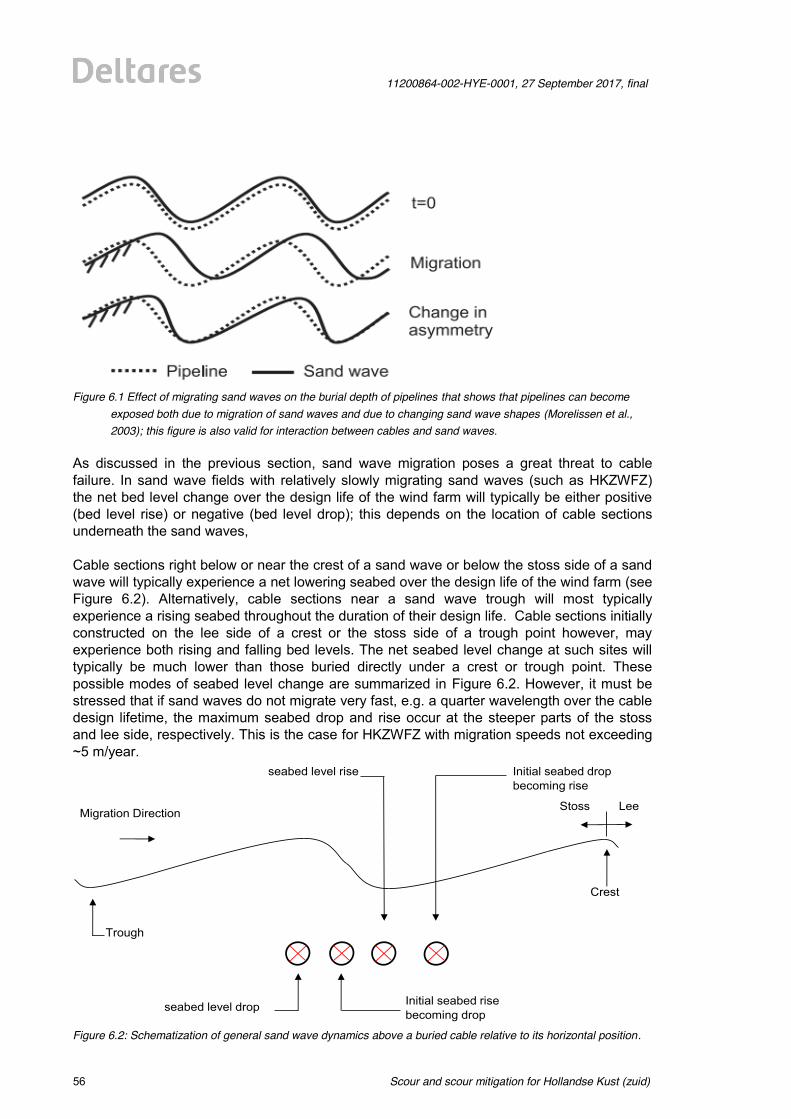
Scour and scour mitigation for Hollandse Kust (zuid)
11200864-002-HYE-0001, 27 September 2017, final
56 of 64
Figure 6.1 Effect of migrating sand waves on the burial depth of pipelines that shows that pipelines can become
exposed both due to migration of sand waves and due to changing sand wave shapes (Morelissen et al., 2003); this figure is also valid for interaction between cables and sand waves.
As discussed in the previous section, sand wave migration poses a great threat to cable failure. In sand wave fields with relatively slowly migrating sand waves (such as HKZWFZ) the net bed level change over the design life of the wind farm will typically be either positive (bed level rise) or negative (bed level drop); this depends on the location of cable sections underneath the sand waves, Cable sections right below or near the crest of a sand wave or below the stoss side of a sand wave will typically experience a net lowering seabed over the design life of the wind farm (see Figure 6.2). Alternatively, cable sections near a sand wave trough will most typically experience a rising seabed throughout the duration of their design life. Cable sections initially constructed on the lee side of a crest or the stoss side of a trough point however, may experience both rising and falling bed levels. The net seabed level change at such sites will typically be much lower than those buried directly under a crest or trough point. These possible modes of seabed level change are summarized in Figure 6.2. However, it must be stressed that if sand waves do not migrate very fast, e.g. a quarter wavelength over the cable design lifetime, the maximum seabed drop and rise occur at the steeper parts of the stoss and lee side, respectively. This is the case for HKZWFZ with migration speeds not exceeding ~5 m/year.
Figure 6.2: Schematization of general sand wave dynamics above a buried cable relative to its horizontal position.
Maximum seabed level rise
Migration Direction
Maximum seabed level drop
Initial seabed drop becoming rise
Initial seabed rise becoming drop
Trough
Crest
Stoss Lee
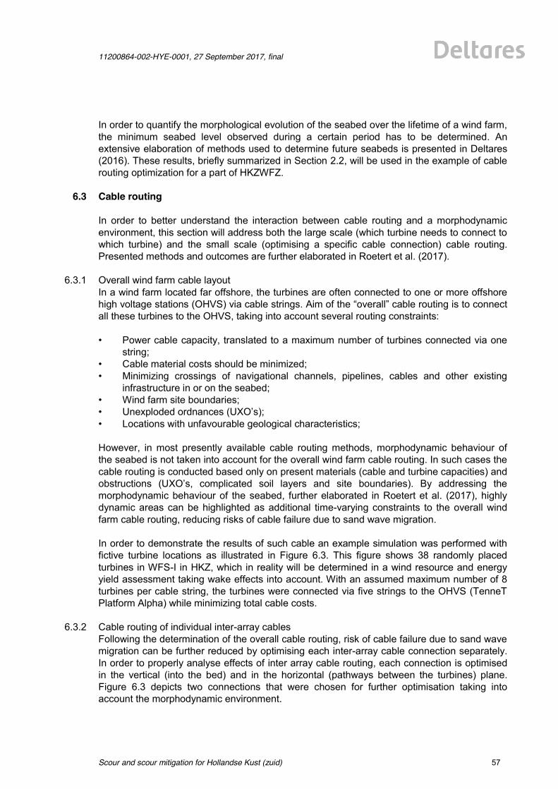
11200864-002-HYE-0001, 27 September 2017, final
Scour and scour mitigation for Hollandse Kust (zuid)
57 of 64
In order to quantify the morphological evolution of the seabed over the lifetime of a wind farm, the minimum seabed level observed during a certain period has to be determined. An extensive elaboration of methods used to determine future seabeds is presented in Deltares (2016). These results, briefly summarized in Section 2.2, will be used in the example of cable routing optimization for a part of HKZWFZ.
6.3 Cable routing In order to better understand the interaction between cable routing and a morphodynamic environment, this section will address both the large scale (which turbine needs to connect to which turbine) and the small scale (optimising a specific cable connection) cable routing. Presented methods and outcomes are further elaborated in Roetert et al. (2017).
6.3.1 Overall wind farm cable layout In a wind farm located far offshore, the turbines are often connected to one or more offshore high voltage stations (OHVS) via cable strings. Aim of the “overall” cable routing is to connect all these turbines to the OHVS, taking into account several routing constraints: • Power cable capacity, translated to a maximum number of turbines connected via one
string; • Cable material costs should be minimized; • Minimizing crossings of navigational channels, pipelines, cables and other existing
infrastructure in or on the seabed; • Wind farm site boundaries; • Unexploded ordnances (UXO’s); • Locations with unfavourable geological characteristics; However, in most presently available cable routing methods, morphodynamic behaviour of the seabed is not taken into account for the overall wind farm cable routing. In such cases the cable routing is conducted based only on present materials (cable and turbine capacities) and obstructions (UXO’s, complicated soil layers and site boundaries). By addressing the morphodynamic behaviour of the seabed, further elaborated in Roetert et al. (2017), highly dynamic areas can be highlighted as additional time-varying constraints to the overall wind farm cable routing, reducing risks of cable failure due to sand wave migration. In order to demonstrate the results of such cable an example simulation was performed with fictive turbine locations as illustrated in Figure 6.3. This figure shows 38 randomly placed turbines in WFS-I in HKZ, which in reality will be determined in a wind resource and energy yield assessment taking wake effects into account. With an assumed maximum number of 8 turbines per cable string, the turbines were connected via five strings to the OHVS (TenneT Platform Alpha) while minimizing total cable costs.
6.3.2 Cable routing of individual inter-array cables Following the determination of the overall cable routing, risk of cable failure due to sand wave migration can be further reduced by optimising each inter-array cable connection separately. In order to properly analyse effects of inter array cable routing, each connection is optimised in the vertical (into the bed) and in the horizontal (pathways between the turbines) plane. Figure 6.3 depicts two connections that were chosen for further optimisation taking into account the morphodynamic environment.
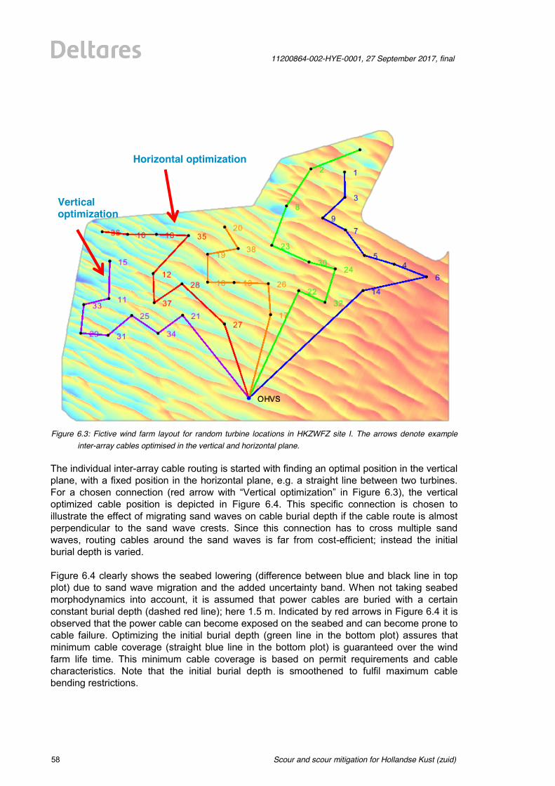
Scour and scour mitigation for Hollandse Kust (zuid)
11200864-002-HYE-0001, 27 September 2017, final
58 of 64
Figure 6.3: Fictive wind farm layout for random turbine locations in HKZWFZ site I. The arrows denote example
inter-array cables optimised in the vertical and horizontal plane. The individual inter-array cable routing is started with finding an optimal position in the vertical plane, with a fixed position in the horizontal plane, e.g. a straight line between two turbines. For a chosen connection (red arrow with “Vertical optimization” in Figure 6.3), the vertical optimized cable position is depicted in Figure 6.4. This specific connection is chosen to illustrate the effect of migrating sand waves on cable burial depth if the cable route is almost perpendicular to the sand wave crests. Since this connection has to cross multiple sand waves, routing cables around the sand waves is far from cost-efficient; instead the initial burial depth is varied. Figure 6.4 clearly shows the seabed lowering (difference between blue and black line in top plot) due to sand wave migration and the added uncertainty band. When not taking seabed morphodynamics into account, it is assumed that power cables are buried with a certain constant burial depth (dashed red line); here 1.5 m. Indicated by red arrows in Figure 6.4 it is observed that the power cable can become exposed on the seabed and can become prone to cable failure. Optimizing the initial burial depth (green line in the bottom plot) assures that minimum cable coverage (straight blue line in the bottom plot) is guaranteed over the wind farm life time. This minimum cable coverage is based on permit requirements and cable characteristics. Note that the initial burial depth is smoothened to fulfil maximum cable bending restrictions.
Vertical optimization
Horizontal optimization
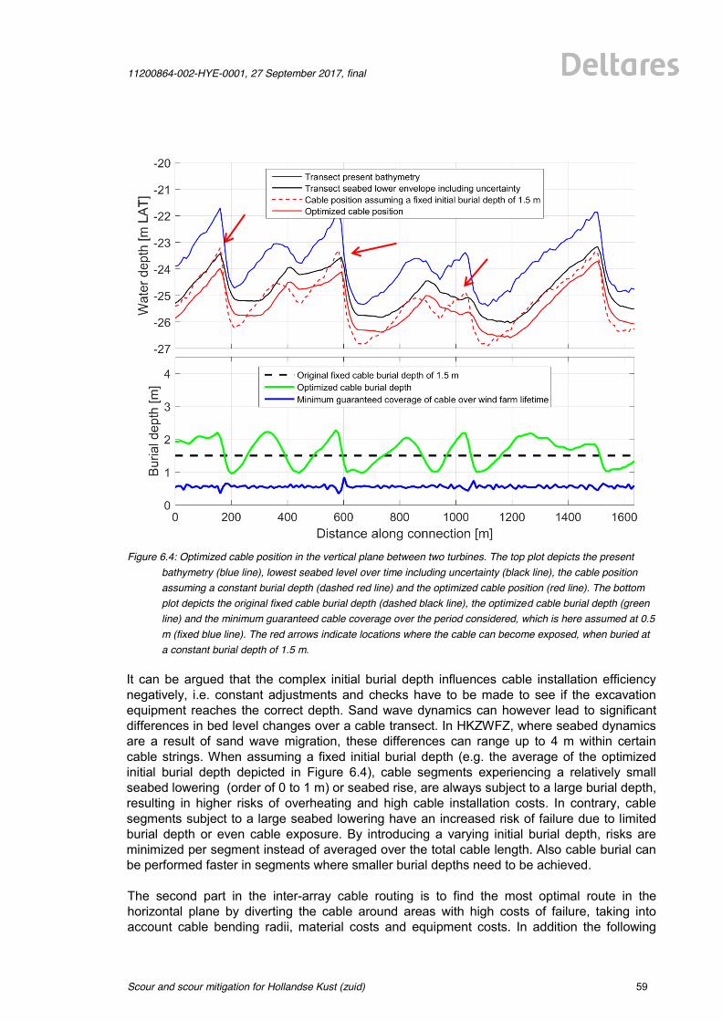
11200864-002-HYE-0001, 27 September 2017, final
Scour and scour mitigation for Hollandse Kust (zuid)
59 of 64
Figure 6.4: Optimized cable position in the vertical plane between two turbines. The top plot depicts the present
bathymetry (blue line), lowest seabed level over time including uncertainty (black line), the cable position assuming a constant burial depth (dashed red line) and the optimized cable position (red line). The bottom plot depicts the original fixed cable burial depth (dashed black line), the optimized cable burial depth (green line) and the minimum guaranteed cable coverage over the period considered, which is here assumed at 0.5 m (fixed blue line). The red arrows indicate locations where the cable can become exposed, when buried at a constant burial depth of 1.5 m.
It can be argued that the complex initial burial depth influences cable installation efficiency negatively, i.e. constant adjustments and checks have to be made to see if the excavation equipment reaches the correct depth. Sand wave dynamics can however lead to significant differences in bed level changes over a cable transect. In HKZWFZ, where seabed dynamics are a result of sand wave migration, these differences can range up to 4 m within certain cable strings. When assuming a fixed initial burial depth (e.g. the average of the optimized initial burial depth depicted in Figure 6.4), cable segments experiencing a relatively small seabed lowering (order of 0 to 1 m) or seabed rise, are always subject to a large burial depth, resulting in higher risks of overheating and high cable installation costs. In contrary, cable segments subject to a large seabed lowering have an increased risk of failure due to limited burial depth or even cable exposure. By introducing a varying initial burial depth, risks are minimized per segment instead of averaged over the total cable length. Also cable burial can be performed faster in segments where smaller burial depths need to be achieved. The second part in the inter-array cable routing is to find the most optimal route in the horizontal plane by diverting the cable around areas with high costs of failure, taking into account cable bending radii, material costs and equipment costs. In addition the following
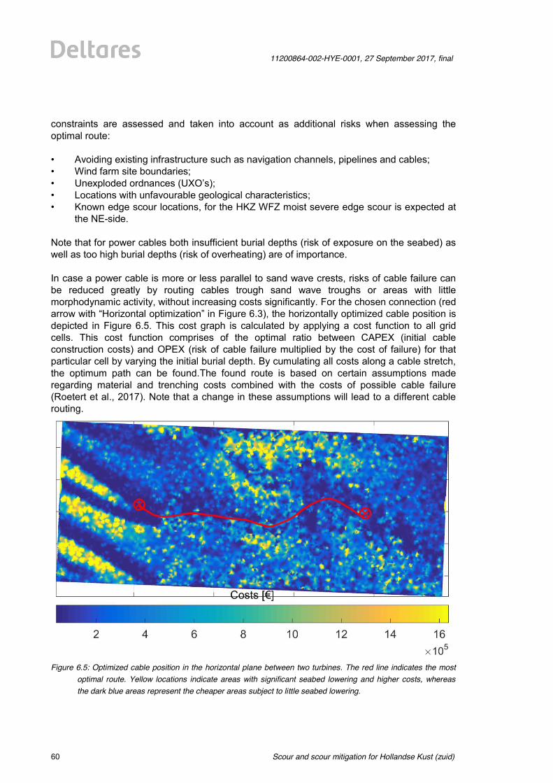
Scour and scour mitigation for Hollandse Kust (zuid)
11200864-002-HYE-0001, 27 September 2017, final
60 of 64
constraints are assessed and taken into account as additional risks when assessing the optimal route: • Avoiding existing infrastructure such as navigation channels, pipelines and cables; • Wind farm site boundaries; • Unexploded ordnances (UXO’s); • Locations with unfavourable geological characteristics; • Known edge scour locations, for the HKZ WFZ moist severe edge scour is expected at
the NE-side. Note that for power cables both insufficient burial depths (risk of exposure on the seabed) as well as too high burial depths (risk of overheating) are of importance. In case a power cable is more or less parallel to sand wave crests, risks of cable failure can be reduced greatly by routing cables trough sand wave troughs or areas with little morphodynamic activity, without increasing costs significantly. For the chosen connection (red arrow with “Horizontal optimization” in Figure 6.3), the horizontally optimized cable position is depicted in Figure 6.5. This cost graph is calculated by applying a cost function to all grid cells. This cost function comprises of the optimal ratio between CAPEX (initial cable construction costs) and OPEX (risk of cable failure multiplied by the cost of failure) for that particular cell by varying the initial burial depth. By cumulating all costs along a cable stretch, the optimum path can be found.The found route is based on certain assumptions made regarding material and trenching costs combined with the costs of possible cable failure (Roetert et al., 2017). Note that a change in these assumptions will lead to a different cable routing.
Figure 6.5: Optimized cable position in the horizontal plane between two turbines. The red line indicates the most
optimal route. Yellow locations indicate areas with significant seabed lowering and higher costs, whereas the dark blue areas represent the cheaper areas subject to little seabed lowering.
11200864-002-HYE-0001, 27 September 2017, final
Scour and scour mitigation for Hollandse Kust (zuid)
61 of 64
Clearly visible is the cable routing around a high cost area. By comparing the costs in Figure 6.5 with the predicted seabed lowering, it is concluded that the high costs areas (yellow areas) are located in places where seabed lowering is most severe. As discussed in Section 6.2, these areas correspond to the stoss sides (SW) close to the sand wave crests. The cheaper parts (dark blue) are located in the sand wave troughs and subject to little or no seabed lowering.
Scour and scour mitigation for Hollandse Kust (zuid)
11200864-002-HYE-0001, 27 September 2017, final
62 of 64
7 Conclusions and recommendations
7.1 Conclusions Offshore structures can either be protected against scour or be designed such that scour development can be allowed. In this study three main groups of scour mitigation strategies were presented:
A. free scour development B. immediate scour protection C. monitor and react
Next, distinction was made between the (autonomous) morphodynamic activity of the seabed:
S. stable seabed L. lowering seabed R. rising seabed
To decide which strategy can best be adopted for a certain foundation type and specific location, information was presented on how to predict the scour depth (when not protected: relevant for Strategy A and C) and how to protect against scour (Strategy B), both taking into account the morphodynamic scenarios of stable, lowering and rising seabeds. It can be concluded that for monopiles an easy-applicable, well-proven solution is to place the monopiles just north-east of the sand wave crests or even on top of the sand wave crests and to apply a scour protection to maintain a more or less fixed seabed level around the foundation. In the first case a slightly longer pile is needed, while in the second case a longer scour protection is recommended to cater for the lowering seabed. Other solutions are also possible, though, such as leaving out the scour protection completely at locations with a rising seabed, when scour protection costs outweigh the costs for additional steel consumption. Gravity-Based-Structures will typically need a scour protection due to too severe scour development in the mobile seabeds in HKZ and the low tolerance for scour due to undermining risks. Locations with a significantly lowering seabed are best to be avoided. Jacket structures are expected to experience significant scour development as well, but as long as they are not located in areas with lowering seabeds and cable free spanning risks are mitigated by proper cable protection measures (such as application of cable stiffeners) they can be designed for free scour development. This does not hold for Suction Bucket Jackets: due to the limited penetration depth of the suction cans and the large scour potential in HKZ, scour protection is always recommended in HKZ. Self-installable systems look promising here.
11200864-002-HYE-0001, 27 September 2017, final
Scour and scour mitigation for Hollandse Kust (zuid)
63 of 64
7.2 Recommendations All presented values for (edge) scour depths, rock gradings, scour protection materials, burial depths etc. are best-estimate values without any safety factors included. The reason for providing best-estimate and not conservative values is to support designers and developers in an early phase with most probable values. However, it is strongly recommended to perform more detailed, site- and structure-specific computations at a later stage. Further optimization for scour predictions and/or scour protection designs can be achieved by means of physical model testing. Improvement of cable routing can be achieved by smart cable routing with actual foundation locations and additional constraints added to the routing routines. In a morphodynamic area such as HKZ, it is strongly recommended to always take predicted seabed changes into account right from the beginning.
References Allianz Global Corporate & Speciality (2016). Power under the sea. Retrieved from http://www.agcs.allianz.com/insights/expert-risk-articles/power-under-the-sea/ Bolle, A., De Winter, J., Goossens, W. Haerens, P., Dewaele, G. (2012), Scour monitoring around offshore jackets and gravity based foundations. Proceedings of 6th International Conference on Scour and Erosion, 27-31 August 2012, Paris. Deltares (2016). Morphodynamics of Hollandse Kust (zuid) Wind Farm Zone; Prediction of seabed level changes between 2016 and 2051. Ref: 1230851-000-HYE-0003; final report, 22 December 2016. (Available through: http://offshorewind.rvo.nl/file/view/47910422/report-morphodynamics-of-hollandse-kust-zuid-wind-farm-zone-deltares). DHI (2017). Wind Farm Zone Hollandse Kust (zuid) & Hollandse Kust (noord) - Metocean Study; final report, 15 March 2017 (retrieved from: http://offshorewind.rvo.nl/file/view/ 51102522/report-metocean-study-dhi). Dienst Hydrografie (2007), Memorie Noordzee reductiematrix 2006 (in Dutch). Koninklijke Marine, Ministerie van Defensie, dated April 2007. DNV GL (2016). Support Structures for wind turbines. Standard DNVGL-ST-126. Edition April 2016 (retrieved from: http://rules.dnvgl.com/docs/pdf/dnvgl/ST/2016-04/DNVGL-ST-0126.pdf). GCube Underwriting Ltd. (2016). Offshore Cable Claims Severity Increases by 25% in 2015; news item about: Down to the Wire: An Insurance Buyer’s Guide to Subsea Cabling Incidents. (retrieved from http://www.gcube-insurance.com/en/press/offshore-cable-claims-severity-increases-by-25-in-2015/).
Scour and scour mitigation for Hollandse Kust (zuid)
11200864-002-HYE-0001, 27 September 2017, final
64 of 64
Harris, J.M., Whitehouse, R.J.S., Sutherland, J. (2011), Marine scour and offshore wind -lessons learnt and future challenges. Proc. of the 30th International Conference on Ocean, Offshore and Arctic Engineering OMAE2011. June 19-24, 2011, Rotterdam, The Netherlands. Morelissen, R., Hulscher, S. J. H. M., Knaapen, M. A. F., Németh, A. A., Bijker, R. (2003). Mathematical modelling of sand wave migration and the interaction with pipelines. Coastal Engineering, 48(3), 197-209. Müller, W. W., Saathoff, F. (2015). Geosynthetics in geoenvironmental engineering. Science and technology of advanced materials, 16(3), 034605. Németh, A.A. (2003). Modelling offshore sand waves. (Doctoral dissertation), University of Twente. Nielsen, A.W., Hansen, E.A. (2007), Time-varying wave and current-induced scour around offshore wind turbines. Proc. 26th Int. Conference on Offshore Mechanics and Arctic Engineering OMAE2007, June 10-15 2007, San Diego, USA Petersen T.U., Sumer, B.M., Freds¢e, J., Raaijmakers, T.C., Schouten, J.J. (2015), Edge scour at scour protections around piles in the marine environment - Laboratory and field investigation. Coastal Engineering, Vol. 106, 2015, p. 42-72 Raaijmakers, T.C., Rudolph, D. (2008). Time-dependent scour development under combined current and wave conditions – laboratory experiments. Proceedings of ICSE-4, Tokyo, Japan. Raaijmakers, T.C., Joon, T., Segeren, M.L.A., Meijers, P. (2013a), Scour: to protect or not to protect? That's the question. Feasibility of omitting scour protection. Proceedings EWEA Offshore 2013 Frankfurt. Raaijmakers, T.C., De Sonneville, B., Rudolph, D. (2013b), Joint Industry Project "OSCAR" on Offshore SCour And Remedial measures. Proceedings of 14th International Conference "The Jack-up Platform", Design Construction and Operation. 17-18 September 2013, London, England. Raaijmakers, T.C., Velzen G. van, Riezebos, H.J. (2014), Dynamic scour prediction for offshore monopiles; validation against laboratory and field measurements. Proceedings of 7th International Conference of Scour and Erosion, 2-4 December 2014, Perth, Australia. Riezebos, H.J., Raaijmakers, T.C., Tönnies-Lohmann, A., Waßmuth, S., Van Steijn P.W. (2016), Scour protection design in highly morphodynamic environments. Proceedings 8th International Conference on Scour and Erosion, 12-15 September 2016, Oxford, UK Roetert, T. J., Raaijmakers, T. C., Borsje, B. W. (2017). Cable route optimization for offshore wind farms in morphodynamic areas. Paper presented at the International Ocean and Polar Engineering Conference, June 25-30 2017, San Francisco, CA, USA. Rudolph, D., Raaijmakers, T. C., Stam, C. J. M. (2008). Time-dependent scour development under combined current and wave conditions - hindcast of field measurements. Proceedings of ICSE-4, Tokyo, Japan.
11200864-002-HYE-0001, 27 September 2017, final
Scour and scour mitigation for Hollandse Kust (zuid)
65 of 64
Sheppard, D.M., Miller, Jr., W. (2006). Live-Bed Local Pier Scour Experiments. Journal of Hydr. Engrg. 132, 635(2006). Shields, A. (1936). "Anwendung der Aehnlichkeitsmechanik und der Turbulenz Forschung auf die Geschiebebewegung." Mitt. der Preussische Versuchanstalt für Wasserbau und Schiffbau, Berlin, Germany, No. 26. Sonneville, B. de, Rudolph D., Raaijmakers T.C., Hunt R., Rietema, K. (2010a), Operational scour management for safe jack-up operations (OMAE2011 - 49718). Proceedings OMAE-14, June 19-24, 2011, Rotterdam, The Netherlands. Sonneville, B. de, Rudolph D., Raaijmakers T.C. (2010b), Scour Reduction by Collars around Offshore Monopiles, Proc. of the Fifth International Conference on Scour and Erosion (ICSE-5), November 7-10, 2010, San Francisco, CA. Soulsby, R.L. (1997). Dynamics of marine sands. A manual for practical applications. Thomas Telford, London. Sumer, B.M., Fredsøe, J. (2002), The mechanics of scour in the marine environment. Advanced Series on Ocean Engineering - Volume 17. New Jersey: World Scientific. Sumer, B.M., Fredsøe, J. (2006), Hydrodynamics Around Cylindrical Structures. Advanced Series on Ocean Engineering - Volume 25, World Scientific, New Jersey. Tavouktsoglou, N.S., Harris, J.M., Simons, R.R., Whitehouse, R.J.S. (2017). Equilibrium Scour-Depth Prediction around Cylindrical Structures. Journal of Waterway, Port, Coastal, and Ocean Engineering, 143(5). Weisse, R., Plüß, A. (2006). Storm-related sea level variations along the North Sea coast as simulated by a high-resolution model 1958-2002. Ocean Dynamics, 56, 16-25. Weisse, R. Günther, H. (2007). Wave climate and long-term changes for the Southern North Sea obtained from a high-resolution hindcast 1958-2002. Ocean Dynamics, doi:10.1007/s10236-0060094-x. Whitehouse, R.J.S. (1998), Scour at marine structures. London: Thomas Telford Limited. Whitehouse, R.J.S. (2011). The nature of scour development and scour protection at offshore windfarm foundations. Marine Pollution Bulletin 62 (2011) 73–88
The creative commons license terms 4.0 CC BY SA apply to this material. Please take notice of the general terms “Creative Commons Attribution 4.0 International public License” before starting to use the license. These terms can be accessed by clicking on this link https://creativecommons.org/licenses/
This investigation was carried out by , commissioned by RVO.nl, an agency of the Ministry of Economic Affairs. Whilst a great deal of care has been taken in compiling the contents of this investigation, RVO.nl can not be held liable for any damages resulting from any inaccuracies and/or outdated information.
The information in this document is valid at the time of publishing (see month/year). Updates will be published on the website http://offshorewind.rvo.nl/ at the relevant sitemap (Hollandse Kust (zuid)/Hollandse Kust (noord), General Information, submap Revision Log and Q & A. In the Revision Log is indicated whichversions are the latest and what the changes are in relation to previous versions. The documents can be found at the relevant sites, indicated in the Revision Log.
ContactsNetherlands Enterprise Agency (RVO.nl)Croeselaan 15 | 3521 BJ | UtrechtP.O. Box 8242 | 3503 RE | Utrechtwww.rvo.nl / http://english.rvo.nl
Netherlands Enterprise Agency (RVO.nl) | September 2017