Embed Size (px)
Citation preview

Journal of Hydraulic Research Vol. 00, No. 0 (2003), pp. 1–14
© 2003 International Association of Hydraulic Engineering and Research
Scour of rock due to the impact of plunging high velocity jets Part I:A state-of-the-art review
Affouillement du rocher par impact de jets plongeants à haute vitesse Partie I:Un résumé de l’état des connaissancesERIK BOLLAERT, Senior Research Associate, Laboratory of Hydraulic Constructions, EPFL, CH-1015 Lausanne, SwitzerlandE-mail: [email protected]
ANTON SCHLEISS, Professor and Director, Laboratory of Hydraulic Constructions, EPFL, CH-1015 Lausanne, SwitzerlandE-mail: [email protected]
ABSTRACTThis paper presents the state-of-the-art on methods to estimate rock scour due to the impingement of plunging high velocity water jets. The followingtopics are addressed: empirical formulae, semi-empirical and analytical approaches, determination of extreme pressure fluctuations at plunge poolbottoms and, finally, the transfer of these pressure fluctuations in joints underneath concrete slabs or rock blocks. Available methods on rock scour havebeen thoroughly investigated on their ability to represent the main physical-mechanical processes that govern scour. This reveals lack of knowledge onturbulence and aeration effects, as well as on transient pressure flow conditions in rock joints. These aspects may significantly influence the destructionof the rock mass and should be accounted for in scour evaluation methods. Their relevance has been experimentally investigated by dynamic pressuremeasurements at modeled plunge pool bottoms and inside underlying one-and two-dimensional rock joints. Test results are described and discussedin Part II of this paper.
RÉSUMÉLe présent article résume le savoir-faire des méthodes d’évaluation de l’affouillement du rocher due à l’impact de jets d’eau à haute vitesse. Il traitenotamment des formules empiriques et approches analytiques, des fluctuations de pressions extrêmes dans des fosses d’affouillement, et finalementdu transfert de pressions dynamiques sous des dalles en béton ou des blocs de rocher. Une comparaison de l’état actuel des connaissances avec lesprocessus physiques du phénomène indique un manque de savoir-faire dans les domaines de la turbulence et de l’aération, ainsi que des écoulementsnon-stationnaires dans les fissures du rocher. Ces aspects peuvent fortement influencer la destruction du rocher et, par conséquent, doivent êtreconsidérés dans des méthodes d’évaluation. Leur importance a été investiguée expérimentalement par des mesures de pressions dynamiques sur lefond de fosses d’affouillement et à l’intérieur de fissures du rocher. Les résultats des mesures sont décrits et discutés dans la Partie II de l’article.
Keywords: Rock scour; state-of-the-art; transient pressure waves; future research.
1 Introduction
Hydraulic structures spilling excess water from dam reservoirshave been a major engineering concern for a long time. Thetransfer of water to the downstream river may scour the dam foun-dation and the downstream riverbed. On the long term, this scourprocess may create structural safety problems. Hence, accurateprediction of time evolution and ultimate scour depth is required.
Ultimate scour depth is traditionally estimated by use ofempirical or semi-empirical formulae that partially neglect basicphysical processes involved. Especially the role of fluctuatingdynamic pressures in plunge pools and their transfer inside under-lying rock joints is unknown. Also, empirical expressions areoften only applicable to the specific conditions for which theywere developed (Whittaker and Schleiss, 1984). They neglect theinfluence of aeration on dynamic pressures and cannot correctlysimulate the resistance of the rock against progressive break-up.
Revision received
1
Since the 1960’s, fluctuating dynamic pressures have beenmeasured and described by their statistical characteristics. Hence,methods based on extreme positive and negative pressure pulsesclarified dynamic uplift of stilling basin concrete linings andscour hole formation in jointed rock. During the 1980’s and1990’s, the influence of time-averaged (Montgomery, 1984;Reinius, 1986; Otto, 1989) and instantaneous (Fiorotto andRinaldo, 1992; Liu et al., 1998; Fiorotto and Salandin, 2000)pressure differences over and under concrete slabs or rock blockshas been investigated experimentally and described theoretically.
Scouring is a highly dynamic process that is governed by theinteraction of three phases (air–water–rock). This dynamic char-acter is highlighted by the appearance of significant transientpressure wave phenomena (oscillations, resonance conditions)inside rock joints, due to the bounded geometry of the joints.Two physical processes are of major importance: (1) hydrody-namic jacking, causing a break-up of the rock mass by progressive
2 Erik Bollaert and Anton Schleiss
h
t
dm
H q, Vj
Dj
mounding
free lling
jet
aeratedpool
Plunging jet impact
Diffusive shear-layer
Bottom pressure fluctuations
Hydrodynamic fracturing
Hydrodynamic uplift
Transport downstream
5
4
3
1
6
6
5
4
3
2
1
Y
fa
2
Figure 1 Main parameters and physical-mechanical processes respon-sible for scour formation.
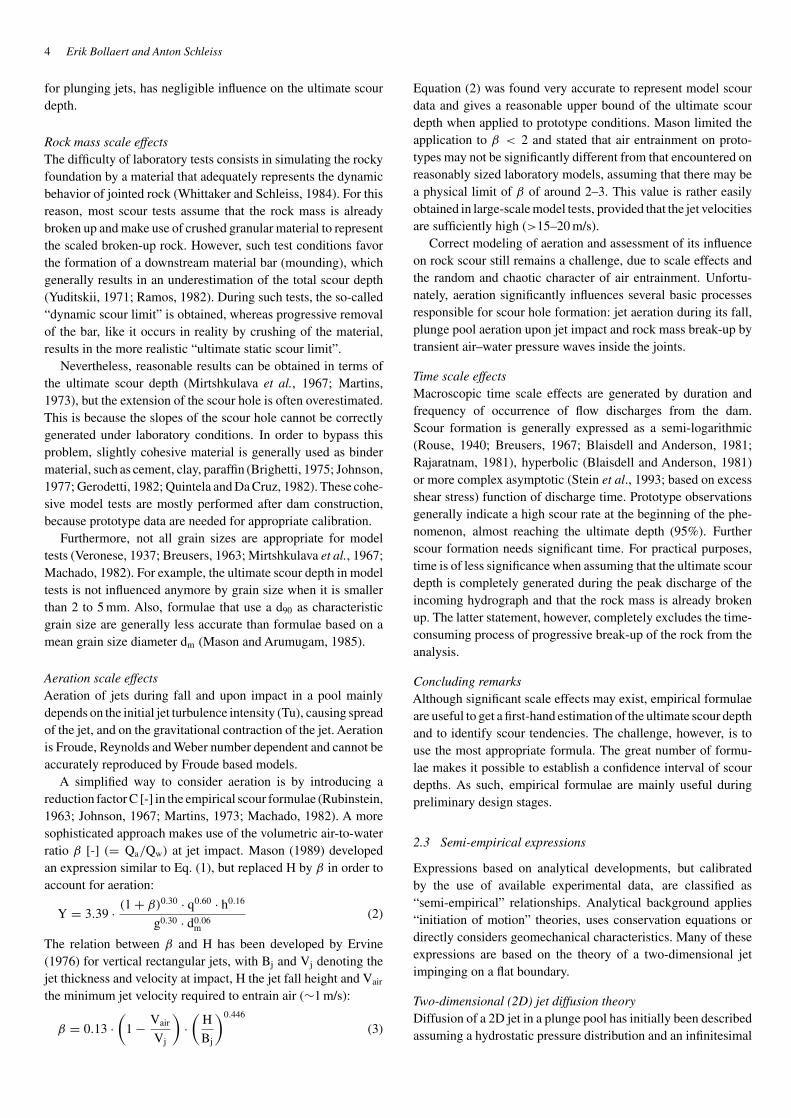
growing of its joints and faults, and (2) hydrodynamic uplift,ejecting distinct rock blocks from their mass. Presently, noapproach is able to describe these phenomena, due to their com-plex behavior. More reliable scour evaluation should accountfor the influence of transient pressure wave phenomena on theinstantaneous pressures inside rock joints.
Scour formation can be described by a consecutive series ofphysical-mechanical processes (Fig. 1): (1) aerated jet impact,(2) turbulent shear-layer diffusion in plunge pool, (3) fluctuatingdynamic pressures at the water–rock interface, (4) propagationof these pressures into underlying rock joints and hydraulic frac-turing of the rock, (5) dynamic uplift of single rock blocks,and finally (6) downstream displacement and/or deposition(mounding) of the broken-up material.
An overview of existing scour evaluation methods distin-guishes between empirical formulae (based on field or laboratoryobservations), combined analytical-empirical methods (combin-ing empiricism with some physical background), methods thatconsider extreme values of fluctuating pressures at the plungepool bottom, and, finally, methods based on time-averagedor instantaneous pressure differences over and under the rockblocks. At the end of the paper, a theoretical framework fora physically-based method to evaluate rock scour and its timeevolution is outlined. The method is based on the transient andtwo-phase nature of air–water pressure wave propagation insiderock joints.
2 Existing methods to evaluate ultimate scour depth
2.1 Parametric synthesis
Table 1 provides an overview of the most common methods toevaluate scour due to high-velocity plunging jets: empirical for-mulae, semi-empirical expressions, plunge pool bottom pressurefluctuations and pressure difference techniques. The parametersthat are used by each of these methods are subdivided into three
groups, according to the relevant phases (water, rock and air).Time evolution is added as a fourth group.
2.2 Empirical expressions
Empirical formulae are a common tool for hydraulic design cri-teria because easy to apply. Model and prototype results arerelated to the main parameters of the formula in a straightfor-ward manner, by use of some general mathematical technique(e.g. dimensional analysis). With a minimum of physical back-ground, a global evaluation of the problem is performed andgeneral tendencies can be outlined.
However, the complete physical background is not accountedfor and special care has to be taken when applying these formulae.This was pointed out by Mason and Arumugam (1985), whoanalyzed a large number of existing formulae. The accuracy of thedifferent formulae showed substantial differences whether modelor prototype conditions were used as input for the parameters.Beside the difficulty to simulate geomechanic aspects or flowturbulence on laboratory scaled model tests, this points out thatempirical formulae may be affected by significant scaling effects.
General scour expressionIn general, scour formulae valid for plunging jet impact expressthe ultimate scour depthY [m], defined as the scour depth beyondthe original bed level, t [m], plus the tailwater depth, h [m],according to the specific discharge, q [m2/s], the fall height,H [m], and the characteristic particle diameter of the downstreamriverbed, d [m]. Some authors (e.g. Martins, 1973) added the tail-water depth h [m] as specific parameter in the formula. Masonand Arumugam (1985) compared the application of 25 such for-mulas to 26 sets of scour data from prototypes and 47 sets of scourdata from model tests. Their best fit of both model and prototypeconditions resulted in the following general form (see Fig. 1 forparameters):
Y = t + h = K · Hy · qx · hw
gv · dzm
(1)
where K = (6.42 − 3.10 · H0.10), v = 0.30, w = 0.15, x =(0.60 − H/300), y = (0.15 − H/200) and z = 0.10.
This dimensional formula (using SI units) is applicable forfree jets issuing from flip buckets, pressure outlets and overflowworks. It gives results with a standard deviation of the resultsof 25% for model test conditions and 30% for prototype testconditions. The applicability for the fall height H lies between0.325 and 2.15 m for models, and 15.82 and 109 m for proto-types. It covers cohesive and non-cohesive granular models, withmodel mean particle sizes dm between 0.001 and 0.028 m. Forprototype rock, it considers a mean equivalent particle size dm of0.25 m. Mason and Arumugam also found that consideration ofthe jet impact angle (Mirtskhulava et al., 1967; Martins, 1973;Chee and Kung, 1974; Mason, 1983) didn’t improve the accu-racy of the results. This is in accordance with a study performedby Fahlbusch (1994), who found that a jet impact angle of 60◦
to 90◦, which covers most of the angles encountered in practice
Scour of rock due to the impact of plunging high velocity jets Part I: A state-of-the-art review 3
Tabl
e1
Exi
stin
gm
etho
dsto
eval
uate
ultim
ate
scou
rdep
than
dsu
mm
ary
ofhy
drau
lic,g
eom
echa
nic
and
aera
tion
para
met
ers.
(Ref
eren
ces
from
befo
re19
84ar
egi
ven
inW
hitta
kera
ndSc
hlei
ss,1
984,
and/
orM
ason
and
Aru
mug
am,1
985,
the
othe
rre
fere
nces
are
liste
dat
the
end
ofth
ear
ticle
.)A
utho
rsm
arke
dw
ith∗
prop
ose
anex
pres
sion
base
don
prot
otyp
eco
nditi
ons
orob
serv
atio
ns.
Type
Yea
rA
utho
r(s)
App
licab
ility
Tim
eH
ydra
ulic
char
acte
rist
ics
Geo
mec
hani
calc
hara
cter
istic
sA
erat
ion
char
acte
rist
ics
Hyd
rost
atic
Hyd
rody
nam
icG
ran.
soil
Join
ted
rock
mas
s
Tq
hH
gV
jθ
RM
SS x
x(f
)tr
ans
d mw
sρ
sσ
c,σ
tR
QD
Nj
zα
φj
Cβ
Tu
Lb
[-]
[m2
/s]
[m]
[m]
[m/s
2]
[m/s
][◦ ]
[-]
[m2
][-
][m
m]
[m/s
][k
g/m
3]
[N/m
2]
[%]
[-]
[-]
[◦ ][◦ ]
[-]
[-]
[%]
[m]
Em
piri
cal
1932
Scho
klits
chpl
ungi
ngje
t–
�–
�–
––
––
–�
––
–-
–-
––
–-
–-
1937
Ver
ones
eA
hori
z.&
plun
ging
jet
–�
–�
––
––
––
�–
––
––
––
––
––
–
1937
Ver
ones
eB
asA
,but
d m<
0.00
5m
–�
–�
––
––
––
––
––
––
––
––
––
–
1939
Jaeg
erpl
ungi
ngje
t–
��
�–
––
––
–�
––
––
––
––
––
––
1953
Dod
diah
etal
.pl
ungi
ngje
t�
�–
�–
––
––
–�
�–
––
––
––
––
––
1957
Har
tung
plun
ging
jet
–�
–�
�–
––
––
�–
––
––
––
––
––
–
1963
Rub
inst
ein
ski-
jum
p,ro
ckcu
bes
––
��
��
�–
––
––
––
––
�–
–�
––
–
1966
Dam
leet
al.∗
ski-
jum
p–
�–
�–
––
––
––
––
––
––
––
––
––
1967
Kot
oula
spl
ungi
ngje
t–
�–
�–
––
––
–�
––
––
––
––
––
––
1969
Che
ean
dPa
diya
rfli
pbu
cket
–�
–�
––
––
––
�–
––
––
––
––
––
–
1974
Che
ean
dK
ung
plun
ging
jet
–�
–�
�–
�–
––
�–
––
––
––
––
––
–
1973
Mar
tins
Apl
ungi
ngje
t,ro
ckcu
bes
–�
��
––
�–
––
––
––
––
�–
––
––
–
1975
Mar
tins
Bsk
i-ju
mp
–�
–�
––
––
––
––
––
––
––
––
––
–
1978
Tara
imov
ich
ski-
jum
p–
––
�–
��
––
––
�–
––
––
––
––
––
1981
INC
YT
Hpl
ungi
ngje
t–
�–
�–
––
––
––
––
––
––
––
––
––
1982
Mac
hado
Apl
ungi
ngje
t,ro
cky
bed
–�
–�
�–
––
––
�–
––
––
––
–�
––
–
1982
Mac
hado
Bpl
ungi
ngje
t,ro
cky
bed
–�
–�
�–
––
––
––
––
––
––
–�
––
–
1985
Mas
onan
dA
rum
ugam
∗pl
ungi
ngje
t–
��
��
––
––
–�
––
––
––
––
––
––
1989
Mas
onpl
ungi
ngje
t–
��
��
––
––
–�
––
––
––
––
–�
––
Sem
i-em
piri
cal
1960
Mik
hale
vpl
ungi
ngje
t–
��
��
–�
––
–�
––
––
––
––
––
––
1967
Mir
tskh
ulav
aet
al.∗
plun
ging
jet,
rock
ybe
d–
��
��
��
––
––
��
�–
–�
––
�–
––
1967
Pore
han
dH
efez
circ
.sub
mer
ged
imp.
jet
–�
–�
–�
––
––
�–
�–
––
––
––
––
–
1975
Zvo
ryki
nsk
i-ju
mp
––
�–
–�
�–
––
––
––
––
––
––
––
–
1983
Mih
and
Kab
irci
rc.s
ubm
erge
dim
p.je
t–
–�
–�
��
––
–�
–�
––
––
––
––
––
1985
Che
ean
dY
uen
plun
ging
jet
––
�–
��
�–
––
�–
�–
––
––
––
––
–
1985
Spur
r∗pl
ungi
ngje
t�
��
��
��
––
–�
––
��
��
�–
––
––
1991
Bor
man
nan
dJu
lien∗
grad
e-co
ntro
l,pl
ung.
jet
–�
––
��
�–
––
�–
�–
––
––
––
––
–
1993
Stei
net
al.
plun
ging
jet
�–
––
��
�–
–�
––
––
––
––
––
––
–
1994
Fahl
busc
hge
nera
l–
��
–�
��
––
–�
––
�–
––
––
–�
––
1998
Ann
anda
le&
al.∗
gene
ral
–�
��
��
�–
––
�–
��
��
��
�–
�–
–
1998
Hof
fman
sge
nera
l–
��
–�
��
––
–�
–�
––
––
––
–�
––
Plun
gepo
olpr
es-
sure
fluct
uatio
ns
1983
Xu
Duo
Min
gre
ctan
g.im
ping
ing
jet
–�
��
��
��
�–
––
––
––
––
––
––
–
1985
Cui
Gua
ngTa
ore
ctan
g.im
ping
ing
jet
–�
��
��
��
�–
––
––
––
––
––
––
–
1987
Fran
zetti
and
Tand
aci
rcul
arim
ping
ing
jet
–�
��
��
–�
––
––
––
––
––
––
––
–
1991
Arm
engo
ure
ctan
g.fa
lling
napp
e–
��
��
�–
��
––
––
––
––
––
––
––
1991
May
and
Will
ough
byre
ctan
gula
rsl
otje
t–
��
��
�–
��
––
––
––
––
––
–�
��
1994
Puer
tas
and
Dol
zre
ctan
g.fa
lling
napp
e–
��
��
�–
��
––
––
––
––
––
––
––
1997
Erv
ine
&al
.ci
rcul
arim
ping
ing
jet
–�
��
��
–�
�–
––
––
––
––
––
��
�Pr
essu
redi
ffer
ence
tech
niqu
es
1963
Yud
itski
iob
lique
imp.
rect
.jet
–�
––
�–
�–
––
––
�–
––
�–
––
––
–
1986
Rei
nius
para
llelfl
owim
pact
––
�–
��
––
––
––
�–
––
–�
––
––
–
1989
Otto
obliq
ueim
p.re
ct.j
et–
––
–�
��
––
––
–�
––
–�
–�
––
––
1992
Fior
otto
and
Rin
aldo
conc
rete
slab
uplif
t–
��
��
�–
�–
––
–�
––
–�
––
––
––
1998
Liu
&al
.ro
ckbl
ock
uplif
t–
��
��
��
��
––
–�
––
–�
––
––
––
1999
Liu
&al
.vi
brat
ion.
slab
uplif
t–
��
��
��
��
––
–�
––
–�
––
––
––
2000
Fior
otto
and
Sala
ndin
anch
ored
slab
uplif
t–
��
��
�–
��
––
–�
––
–�
––
––
––
Tra
nsie
ntpr
essu
re
jack
ing/
uplif
t
2002
Bol
laer
tve
rtic
alan
dob
lique
impi
ng-
ing
jets
and
naps
,con
cret
esl
ab
and
rock
bloc
kup
lift
��
��
��
��
��
––
��
��
��
��
��
�
4 Erik Bollaert and Anton Schleiss
for plunging jets, has negligible influence on the ultimate scourdepth.
Rock mass scale effectsThe difficulty of laboratory tests consists in simulating the rockyfoundation by a material that adequately represents the dynamicbehavior of jointed rock (Whittaker and Schleiss, 1984). For thisreason, most scour tests assume that the rock mass is alreadybroken up and make use of crushed granular material to representthe scaled broken-up rock. However, such test conditions favorthe formation of a downstream material bar (mounding), whichgenerally results in an underestimation of the total scour depth(Yuditskii, 1971; Ramos, 1982). During such tests, the so-called“dynamic scour limit” is obtained, whereas progressive removalof the bar, like it occurs in reality by crushing of the material,results in the more realistic “ultimate static scour limit”.
Nevertheless, reasonable results can be obtained in terms ofthe ultimate scour depth (Mirtshkulava et al., 1967; Martins,1973), but the extension of the scour hole is often overestimated.This is because the slopes of the scour hole cannot be correctlygenerated under laboratory conditions. In order to bypass thisproblem, slightly cohesive material is generally used as bindermaterial, such as cement, clay, paraffin (Brighetti, 1975; Johnson,1977; Gerodetti, 1982; Quintela and Da Cruz, 1982). These cohe-sive model tests are mostly performed after dam construction,because prototype data are needed for appropriate calibration.
Furthermore, not all grain sizes are appropriate for modeltests (Veronese, 1937; Breusers, 1963; Mirtshkulava et al., 1967;Machado, 1982). For example, the ultimate scour depth in modeltests is not influenced anymore by grain size when it is smallerthan 2 to 5 mm. Also, formulae that use a d90 as characteristicgrain size are generally less accurate than formulae based on amean grain size diameter dm (Mason and Arumugam, 1985).
Aeration scale effectsAeration of jets during fall and upon impact in a pool mainlydepends on the initial jet turbulence intensity (Tu), causing spreadof the jet, and on the gravitational contraction of the jet. Aerationis Froude, Reynolds and Weber number dependent and cannot beaccurately reproduced by Froude based models.
A simplified way to consider aeration is by introducing areduction factor C [-] in the empirical scour formulae (Rubinstein,1963; Johnson, 1967; Martins, 1973; Machado, 1982). A moresophisticated approach makes use of the volumetric air-to-waterratio β [-] (= Qa/Qw) at jet impact. Mason (1989) developedan expression similar to Eq. (1), but replaced H by β in order toaccount for aeration:
Y = 3.39 · (1 + β)0.30 · q0.60 · h0.16
g0.30 · d0.06m
(2)
The relation between β and H has been developed by Ervine(1976) for vertical rectangular jets, with Bj and Vj denoting thejet thickness and velocity at impact, H the jet fall height and Vair
the minimum jet velocity required to entrain air (∼1 m/s):
β = 0.13 ·(
1 − Vair
Vj
)·(
H
Bj
)0.446
(3)
Equation (2) was found very accurate to represent model scourdata and gives a reasonable upper bound of the ultimate scourdepth when applied to prototype conditions. Mason limited theapplication to β < 2 and stated that air entrainment on proto-types may not be significantly different from that encountered onreasonably sized laboratory models, assuming that there may bea physical limit of β of around 2–3. This value is rather easilyobtained in large-scale model tests, provided that the jet velocitiesare sufficiently high (>15–20 m/s).
Correct modeling of aeration and assessment of its influenceon rock scour still remains a challenge, due to scale effects andthe random and chaotic character of air entrainment. Unfortu-nately, aeration significantly influences several basic processesresponsible for scour hole formation: jet aeration during its fall,plunge pool aeration upon jet impact and rock mass break-up bytransient air–water pressure waves inside the joints.
Time scale effectsMacroscopic time scale effects are generated by duration andfrequency of occurrence of flow discharges from the dam.Scour formation is generally expressed as a semi-logarithmic(Rouse, 1940; Breusers, 1967; Blaisdell and Anderson, 1981;Rajaratnam, 1981), hyperbolic (Blaisdell and Anderson, 1981)or more complex asymptotic (Stein et al., 1993; based on excessshear stress) function of discharge time. Prototype observationsgenerally indicate a high scour rate at the beginning of the phe-nomenon, almost reaching the ultimate depth (95%). Furtherscour formation needs significant time. For practical purposes,time is of less significance when assuming that the ultimate scourdepth is completely generated during the peak discharge of theincoming hydrograph and that the rock mass is already brokenup. The latter statement, however, completely excludes the time-consuming process of progressive break-up of the rock from theanalysis.
Concluding remarksAlthough significant scale effects may exist, empirical formulaeare useful to get a first-hand estimation of the ultimate scour depthand to identify scour tendencies. The challenge, however, is touse the most appropriate formula. The great number of formu-lae makes it possible to establish a confidence interval of scourdepths. As such, empirical formulae are mainly useful duringpreliminary design stages.
2.3 Semi-empirical expressions
Expressions based on analytical developments, but calibratedby the use of available experimental data, are classified as“semi-empirical” relationships. Analytical background applies“initiation of motion” theories, uses conservation equations ordirectly considers geomechanical characteristics. Many of theseexpressions are based on the theory of a two-dimensional jetimpinging on a flat boundary.
Two-dimensional (2D) jet diffusion theoryDiffusion of a 2D jet in a plunge pool has initially been describedassuming a hydrostatic pressure distribution and an infinitesimal

Scour of rock due to the impact of plunging high velocity jets Part I: A state-of-the-art review 5
plunge pool thickness. The concept of a jet of uniform velocityfield penetrating into a stagnant fluid is based on the progressivegrowing of the thickness of the boundary shear layer by exchangeof momentum. This shear layer is characterized by two effects: anincrease of the total cross section of the jet and a correspondingdecrease of the non-viscous wedge-like core between the bound-ary layers, indicated in Fig. 2. Hydrostatic pressure assumptionleads to a constant core velocity. The core length depends onthe inner angle of diffusion αin, about 4–5◦ for submerged jets(= jet outlet is under water level) and around 8◦ for highly turbu-lent impinging jets (McKeogh, 1978, cited in Ervine and Falvey,1987). An overview of studies investigating the core length ispresented at Table 2, were the core extension is determined as Kc
times the jet diameter Dj or the jet width Bj. The scatter of the
Figure 2 2D jet diffusion showing the jet core length (jet developmentregion) and the developed jet region, the inner and outer angles of diffu-sion (McKeogh, 1978, cited in Ervine and Falvey, 1987), and the mainregions of jet impingement (Beltaos and Rajaratnam, 1973).
Table 2 Coefficient Kc of jet core length Lc according to different studies on (circular andrectangular) impinging or submerged jets.
Author Year Kc Jet type Analysis
Albertson et al. 1948 5.2 rectang 2D jet diff. + experimAlbertson et al. 1948 6.2 circular 2D jet diff. + experimHomma 1953 4.8 circular experimentallyCola 1965 7.18 rect/subm cons.eq. + experim.Poreh and Hefez 1967 9 circular 2D jet diffusion theoryHartung and Häusler 1973 5 circ/imp angle of diff. estimateHartung and Häusler 1973 5 rect/imp angle of diff. estimateBeltaos and Rajaratnam 1973 8.26 rectang jet momentum fluxBeltaos and Rajaratnam 1974 5.8–7.4 circular jet momentum fluxFranzetti and Tanda 1987 4.7 circ/imp. 2D jet diff. + experimFranzetti and Tanda 1987 6.03 circ/subm. 2D jet diff. + experimChee and Yuen 1985 3.3 circ/imp dim. analys. of mom.Cui Guang Tao 1985 6.35 rect/imp experimentallyErvine and Falvey 1987 4 circ/imp experimentally + mom.Ervine and Falvey 1987 6.2 circ/subm experimentallyArmengou 1991 3.19 rect/imp experimentallyBormann and Julien 1991 3.24 rect/imp jet diffusion coeff. Cd
Ervine et al. 1997 4–5 circ/imp experimentally
obtained Kc values is probably caused by different jet outlet testconditions.
However, this fundamental 2D jet diffusion concept doesn’taccount for the existence of flow boundaries, which largelymodify the hydrostatic pressure distribution. Several researchersinvestigated the influence of the flow boundary on the jet’s pres-sure and velocity fields. The most complete study of plane andcircular, oblique and vertical jet impingement on a flat and smoothsurface has been done by Beltaos and Rajaratnam (1973, 1974)and Beltaos (1976). They proposed three distinct flow regions:the free jet, the impingement jet and the wall jet region (Fig. 2).The most severe hydrodynamic action of the flow occurs in theimpingement region, near the solid boundary. There, the hydro-static pressure of the free jet region is progressively transformedinto highly fluctuating stagnation pressures and an important wallshear stress (due to lateral jet deflection). Hence, the impingementregion is directly related to scour formation, because the pressurefluctuations that are generated enter underlying rock joints andprogressively break up the rock mass.
Moreover, Bohrer et al. (1998) predicted the velocity decay ofa free falling turbulent rectangular jet in plunge pools, in order todetermine its erosive potential. This has been done for compactand broken-up jets. Compact jets are thereby defined as jets withan intact core region upon impact in the pool. Broken-up jets haveno inner core region anymore upon impact, due to turbulent fluc-tuations at the outer boundaries that progress towards the insideof the jet and that break up the core (Ervine and Falvey, 1987).Furthermore, the study accounted for jet velocity and jet density(or air concentration) at impact. Stream power, defined as the rateof energy dissipation of the jet in the plunge pool, is determined asa function of velocity decay and can be compared with the rock’sresistance to erosion. The latter can be expressed by a generalindex (Annandale’s Erodibility Index method; Annandale, 1995).
6 Erik Bollaert and Anton Schleiss
This method is outlined more in detail in the paragraph dealingwith geomechanical methods.
Initiation of motion conceptThe concept of initiation of motion of riverbed material has beenlargely applied to cohesionless granular material. In a basic the-oretical work, Simons and Stevens (1971) performed a complete3D analysis of the possible hydrodynamic forces and momentson a solid particle. In general, most expressions are based onShields’ critical shear stress (Poreh and Hefez, 1967; Stein et al.,1993). Other studies consider the main forces acting on a solidparticle moved away by jet flow (Mih and Kabir, 1983; Cheeand Yuen, 1985; Bormann and Julien, 1991), or also the streampower of the jet (Annandale, 1995). The scour depth formulaestablished by Bormann and Julien (1991), based on jet diffu-sion and particle stability on scour hole slopes, is of particularinterest because applicable to a wide range of outlet structuresand calibrated on large-scale experiments. For plunging jets, thisformula is comparable to Eq. (1):
t = K · q0.6 · Vj
g0.8 · d0.490
· sin θ (4)
with
K = 3.24 ·[γ · sin φ
(sin(φ + θ) · 2 · (γs − γ ))
]0.8
(5)
A specific weight ratio γs/γ of 2.7 and a submerged angle ofrepose φ of the granular material of 25◦ are assumed. The angleof repose φ depends thereby on the ratio of the critical shear stressrequired to move upslope the granular material to the critical shearstress valid for flat bed conditions. Hoffmans and Verheij (1997)tested Eq. (4) with a large data set and found acceptable accuracyand wide-range applicability.
Conservation equationsApproaches based on the continuity, momentum or energy con-servation equations express the main physical processes in aglobal but exact manner. Fahlbusch (1994) and Hoffmans (1998)calculated the equilibrium scour depth by application of Newton’ssecond law of motion on a mass of fluid particles. They pro-vide accurate and widely applicable scour predictions. Fahlbusch(1994) used 104 model or prototype measurements to verify theaccuracy of his expression:
Y = c2v ·√
q · Vj · sin θ
g(6)
A potential scour estimation error of 40% was observed. Theparameter c2v has an upper limit of 3.92 and an average valueof 2.79, almost identical to the value of 2.83 found by Veronese(1937). Hoffmans (1998) slightly modified Eq. (6) by relatingc2v to the particle diameter d90. For grain diameters beyond12.5 mm, c2v = 2.9. For smaller diameters, c2v = 20/(d90∗)1/3,where d90∗ = d90(� · g/ν2) with � = (γs/γ − 1) = 1.65 andν = 10−6 m2/s. Based on a large data set, 80% of the experi-mental (laboratory) results fell within 0.5 to 2 times the values astheoretically predicted by Eq. (6).
Geomechanical characteristicsThe first attempts to describe the erosion resistance of rockprimarily focused on fracture frequency (RQD) and degree ofweathering (Otto, 1989). However, the stage of rock mass break-up can only be assessed by incorporating the strength of therock matrix. One of the first detailed descriptions of plungepool geology has been proposed by Spurr (1985). He devel-oped a procedure that determines the mean hydraulic energy thatexceeds the rock mass erosion resistance. The procedure alsoaccounts for spill durations. The rock mass erosion resistanceis thereby expressed by the uniaxial compressive strength σc ofthe intact rock, together with the RMR (Rock Mass Rating) afterBieniawski (1984). This forms the basis for a classification of theplunge pool geology into three groups of different erosion resis-tance. An empirical formula for equilibrium scour depth is firstof all calibrated at a reference plunge pool. Application of thiscalibrated formula to the study site is then performed by meansof an index, depending on spill duration and the specific erosionresistance group of the plunge pool geology. Spurr (1985) car-ried out a prototype validation of his approach, however, this waslimited to only one case study.
More recently, as already mentioned, a cooperative DamFoundation Erosion (DFE) study has been conducted by theColorado State University and the US Bureau of Reclamation(Lewis et al. 1996; Annandale et al., 1998; Bohrer et al., 1998)in order to relate stream power of the plunging jet, defined byvelocity decay, to an erodibility index that expresses the rock’serosion resistance (Annandale, 1995).
The rock erosion resistance is related to an index that accountsfor several geological parameters (such as uniaxial compressivestrength σc, Rock Quality Designate RQD, material density ρs,block size and shape, joint set angle αj, joint roughness, etc).These properties can be measured in the field at reasonable costand are quantifiable through tables (Annandale, 1995). Further-more, the influence of the plunge pool air concentration on jetvelocity decay is taken into account for both compact (with core)and broken-up (= fully aerated, no core anymore) jets.
A graphical relationship between this erodibility index andthe jet power has been established for a data set of 150 fieldobservations and available literature data on sediment motion.This allowed defining an erosion threshold relationship for anygiven set of hydraulic conditions and for any type of foundationmaterial (granular soils, rock, etc.). Recently, experiments onprototype scale, simulating the erosion of a fractured blocky-shaped rock mass, confirmed the theoretically derived erosionthreshold (Annandale et al., 1998).
2.4 Plunge pool bottom pressures
Dynamic pressures at the water–rock interface may result fromcore jet impact, occurring for small plunge pool depthsY, or frommacroturbulent shear layer impact, occurring for pool depths Ygreater than 4 to 6 times the jet diameter Dj (based on 2D jetdiffusion theory). The following parameters are relevant: meandynamic pressure, root-mean-square (RMS) value of dynamicpressure fluctuations, extreme positive and negative dynamic
Scour of rock due to the impact of plunging high velocity jets Part I: A state-of-the-art review 7
pressures, and power spectral content of the dynamic pressurefluctuations. These parameters characterize dynamic pressureloading on rock blocks or concrete linings by applying a max-imum pressure underneath a rock block or concrete slab and aminimum pressure on the surface. In this way, a maximum netuplift pressure or force is determined. Ultimate scour depth isreached when this net uplift force is not capable anymore toeject the rock block or the concrete slab. Resistance to upliftis generated by the submerged weight of the slabs or blocks andby eventual shear and interlocking forces along the joints. Forconcrete slabs, anchor stresses may be added to this resistance.
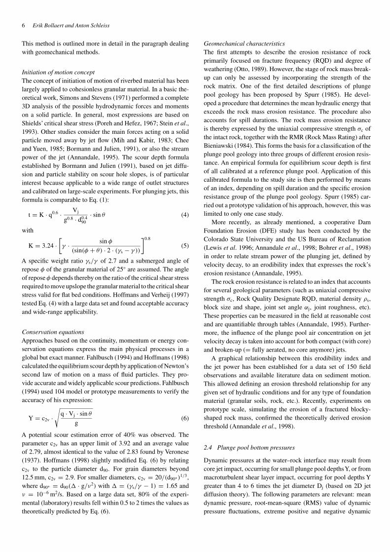
Mean dynamic pressure under the jet’s centrelineThe mean dynamic pressure is expressed in a dimensionless man-ner by means of the Cp coefficient. This coefficient is defined asthe mean dynamic pressure value Hm (in [m]) at the rock surfacedivided by the incoming kinetic energy head of the jet V2
j /2g (in[m]). Figure 3 gives an overview of 11 independent studies thatexpress the Cp coefficient as a function of the ratio of pool depthto jet diameter Y/Dj.
A different behaviour can be observed between circular andrectangular jets, as well as between plunging and submerged jets.The jet core, according to 2D jet diffusion theory, extends up to4–6 times the jet diameter Dj for plunging jets and up to 6–8 timesDj for submerged jets. Moreover, due to spreading and aeration ofthe plunging jet, which cause energy losses, plunging jets attainCp values of maximum 0.8–0.9. It is interesting to observe thatcircular jets have a stronger decrease of Cp with Y/Dj than rectan-gular jets. The reason for this stronger decrease may lie in the def-inition of the impingement width Bj and/or in the fact that jet dif-fusion occurs radially (in every direction) for circular jets insteadof laterally (unidirectional) in case of rectangular jets. The firstaspect may be circumvented by use of an equivalent jet diameter.
Root-mean-square (RMS) value of the dynamic pressurefluctuationsThe C′
p coefficient is defined as the ratio of the RMS-value of thepressure fluctuations H′ (in [m]) over the incoming kinetic energy
0
0.2
0.4
0.6
0.8
1
0 1 2 3 4 5 6 7 8 9 10 11 12 13 14 15 16 17 18 19 20Y/Dj
Cp
Ervine et al. (1997)
Franzetti & Tanda (1987)
Hartung & Häusler (1973)
Ervine et al. (1997)
Franzetti & Tanda (1987)
Beltaos & Rajaratnam (1974)
Puertas (1994)
Hartung & Häusler (1973)
Cola (1965)
Cui G. T. et al. (1985)
Beltaos & Rajaratnam (1973)
circular submerged jet
circular plunging jet
rectangular submerged jet
rectangular plunging jet
Figure 3 Mean dynamic pressure coefficient Cp as a function of Y/Dj.Summary of different studies conducted on circular plunging (triangularsymbols), circular submerged (circular symbols), rectangular plunging(+ symbol) and rectangular submerged (block symbols) jets.
0
0.1
0.2
0.3
0.4
0.5
0.6
0 1 2 3 4 5 6 7 8 9 10 11 12 13 14 15 16Y/Dj
C'p
Ervine et al. (1997) circular plunging jet
Franzetti & Tanda (1987) circular plunging jet
Franzetti & Tanda (1987) circular submerged jet
May & Willoughby (1991) rectangular slot plunging jet
May & Willoughby (1991) rectangular slot submerged jet
Xu Duo-Ming (1983) circular oblique plunging jet
Lencastre (1961) rectangular falling jet
Castillo & Dolz (1989) rectangular falling jet
Jia et al. (2001): best-fit of Ervine et al. (1997), Franzetti and Tanda (1987),
Liu et al. (1998) and Robinson (1992)
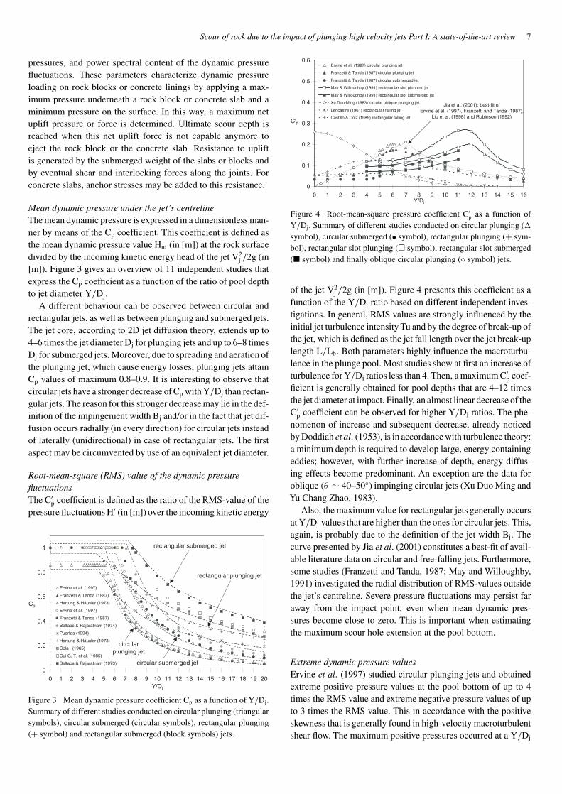
Figure 4 Root-mean-square pressure coefficient C′p as a function of
Y/Dj. Summary of different studies conducted on circular plunging (�symbol), circular submerged (• symbol), rectangular plunging (+ sym-bol), rectangular slot plunging (� symbol), rectangular slot submerged(� symbol) and finally oblique circular plunging (� symbol) jets.
of the jet V2j /2g (in [m]). Figure 4 presents this coefficient as a
function of the Y/Dj ratio based on different independent inves-tigations. In general, RMS values are strongly influenced by theinitial jet turbulence intensity Tu and by the degree of break-up ofthe jet, which is defined as the jet fall length over the jet break-uplength L/Lb. Both parameters highly influence the macroturbu-lence in the plunge pool. Most studies show at first an increase ofturbulence for Y/Dj ratios less than 4. Then, a maximum C′
p coef-ficient is generally obtained for pool depths that are 4–12 timesthe jet diameter at impact. Finally, an almost linear decrease of theC′
p coefficient can be observed for higher Y/Dj ratios. The phe-nomenon of increase and subsequent decrease, already noticedby Doddiah et al. (1953), is in accordance with turbulence theory:a minimum depth is required to develop large, energy containingeddies; however, with further increase of depth, energy diffus-ing effects become predominant. An exception are the data foroblique (θ ∼ 40–50◦) impinging circular jets (Xu Duo Ming andYu Chang Zhao, 1983).
Also, the maximum value for rectangular jets generally occursat Y/Dj values that are higher than the ones for circular jets. This,again, is probably due to the definition of the jet width Bj. Thecurve presented by Jia et al. (2001) constitutes a best-fit of avail-able literature data on circular and free-falling jets. Furthermore,some studies (Franzetti and Tanda, 1987; May and Willoughby,1991) investigated the radial distribution of RMS-values outsidethe jet’s centreline. Severe pressure fluctuations may persist faraway from the impact point, even when mean dynamic pres-sures become close to zero. This is important when estimatingthe maximum scour hole extension at the pool bottom.
Extreme dynamic pressure valuesErvine et al. (1997) studied circular plunging jets and obtainedextreme positive pressure values at the pool bottom of up to 4times the RMS value and extreme negative pressure values of upto 3 times the RMS value. This in accordance with the positiveskewness that is generally found in high-velocity macroturbulentshear flow. The maximum positive pressures occurred at a Y/Dj

8 Erik Bollaert and Anton Schleiss
ratio of 10, while the maximum negative pressures were observedat Y/Dj ratios of only 5. This is because maximum negativedeviations from the mean pressure can only be obtained at ratherhigh mean dynamic pressures, i.e. for low Y/Dj ratios.
Franzetti and Tanda (1987) investigated both circular plung-ing and circular submerged jets. They found that the ratio ofextreme pressure value to RMS value increases with increasingY/Dj and obtained values of up to 8 for Y/Dj = 25–30. This isin accordance with the findings of May and Willoughby (1991),who studied rectangular slot jets. They found that extreme valuesdo not necessarily appear at the point of jet impact. This aspectmay be important when considering net uplift pressures at loca-tions away from the jet impact zone. May and Willoughby alsofound higher positive than negative extremes, appearing at aboutthe same Y/Dj ratios as Ervine et al. (1997), as well as extremesthat are higher for plunging than for submerged jets.
Extreme pressures are often obtained for relatively short mea-suring periods. Their application to prototype conditions might bequestionable at first sight. For example, Toso and Bowers (1988)performed pressure measurements underneath hydraulic jumpsand found extreme values during 24-hours test runs that weretwice as large as the ones obtained during 10-minutes test runs.This phenomenon is in accordance with intermittency of turbu-lent fluctuations. However, extreme pressures only occur duringhigh-frequency pulses and their corresponding spatial persistencyis generally very small. As such, their total energy content is mod-erate, and these pulses can often be considered as insignificant fordesign purposes of large concrete slabs (>5–10 m) of plunge poolbottom linings. For small rock blocks (<1 m), on the contrary,they might be of influence. The relevance of these pulses clearlydepends on the ratio of the spatial persistency (or integral scale)to the characteristic length of the concrete slab or the rock block.
Power spectral content of dynamic pressure fluctuationsThe power spectral content Sxx(f), defined as the decompositionof the variance (σ 2) of the pressure fluctuations as a functionof frequency, determines the frequency content of the pressurefluctuations. Figure 5 represents Sxx(f) in both dimensional anddimensionless manner for circular and rectangular jets, accord-ing to different studies. A log–log representation has been used.Most of the studies show major spectral energy at low frequen-cies, i.e. 0–20 Hz. The energy is mostly contained by eddies atthe scale of the plunge pool water depth. Very little information isavailable for higher frequencies, because high frequencies are dif-ficult to generate on scaled model tests. However, as pointed outin Part II of this paper, higher frequencies may contain sufficientspectral energy to stimulate rock or slab joints to oscillating andeven resonating transient pressures. These transient pressures,although of short-lived character, may be amplified inside jointsand become much higher than the pressures at the water–rockinterface. As such, it is believed that they are directly responsiblefor scour formation by progressive break-up of the rock joints.
Higher frequencies have been studied in the field of turbu-lent flow impinging on flat surfaces (Bearman, 1972; Huot et al.,1986; Ballio et al., 1994). Core jet impact (for Y/Dj < 4–6)generates a spectral content that decays in a linear manner at
1.E–11
1.E–10
1.E–09
1.E–08
1.E–07
1.E–06
1.E–05
1.E–04
1.E–03
1.E–02
1.E–01
1.E+00
1 10 100 1000f [Hz]
Sxx(f
)
May & Willoughby (1991) rect plunging jet-no air-Y/B = 11.6
May & Willoughby (1991) rect submerged jet-no air-Y/B = 10.4
May & Willoughby (1991) rect plunging jet-20% air-Y/B = 11.6
Xu Duo Ming (1983) rectangular oblique jet - Y/B ~ 1
Xu Duo Ming (1983) rectangular oblique jet - Y/B ~ 5
Cui Guang Tao (1985) rectangular plunging jet
Ballio et al. (1992) circular plunging jet - Y/Dj = 7.5
Ballio et al. (1992) circular plunging jet - Y/Dj = 11.1
Puertas & Dolz (1994) rectangular plunging jet
Ervine et al. (1997) circular plunging jet - Y/Dj ~ 2.5
Bollaert (2000) circular plunging jet - Y/Dj = 9.3
Bollaert (2000) circular plunging jet - Y/Dj =2.5
Y/Dj
> 4-6
Y/Dj
< 4-6
f-1
f-7/3
f-9/3
Figure 5 Power spectral content Sxx(f) of dynamic pressure fluctuationsas a function of frequency. Summary of different studies showing thedifference at high frequencies between spectra of core jets (Y/Dj < 4–6)and spectra of developed jets (Y/Dj > 4–6).
log–log scale, even for very high frequencies. The rate of energydecay follows f−1 (f = frequency; Bollaert and Schleiss, 2001a).Developed jet impact (for Y/Dj > 4–6) shows two distinctregions of spectral decay: one in the low and intermediate fre-quency range (up to 50–100 Hz), with a non-negligible amount ofspectral energy, and one at high frequencies (>50–100 Hz), witha rate of energy decay of f−7/3 towards the viscous dissipationrange (Kolmogoroff, 1941). The exact frequency at which thesetwo regions are separated depends on the flow conditions and onthe Y/Dj ratio (or jet development) (Ballio et al., 1992).
In conclusion, simultaneous application of extreme positiveand negative pool bottom pressures over and under rock blocksor concrete slabs may result in a net pressure difference of upto 7 times the RMS value of the pressure fluctuations, or up to1.5–1.75 times the incoming kinetic energy of the impacting jetV2
j /2g. Considering that the combination of a minimum pres-sure all over the slab or block surface with a maximum pressureall underneath is quasi impossible, this provides a conservativedesign criterion. However, it doesn’t consider violent transientphenomena that might occur inside the joints and that mightamplify the net uplift pressures.
2.5 Time-averaged and instantaneous pressure differences
Theoretically, the maximum possible net uplift pressure that maybe obtained on a rock block equals one time the incoming kineticenergy head of the jet V2
j /2g (in [m] of uplift pressure). Thiscorresponds to a complete conversion of the jet’s kinetic energyinto dynamic pressure underneath the block, combined with theabsence of dynamic pressures all over the block’s surface. Inpractice, the situation is more complicated. Dynamic pressuresare always present over the rock’s surface and rock block protru-sion into the turbulent flow field may generate additional upliftpressures due to suction effects.
Yuditskii (1963) and Gunko et al. (1965) where the first stat-ing that time-averaged pressure differences may be responsiblefor rock block uplift. They presented these pressures indimensionless graphs as a function of the length of the block
Scour of rock due to the impact of plunging high velocity jets Part I: A state-of-the-art review 9
and the depth of the pool. They also pointed out the impor-tance of instantaneous dynamic pressures that may enter thejoints and disintegrate the rock. Reinius (1986), based on a studyby Montgomery (1984), investigated the time-averaged dynamicpressures on a rock block subjected to water flowing parallelto its surface and for protruding rock surfaces. The obtainedtime-averaged net uplift pressures were maximum 67% of theincoming kinetic energy V2
j /2g and were found sufficient to causeuplift of the blocks. Hartung and Häusler (1973) highlighted inan experimental way the destructive effects of dynamic pressuresentering rock joints and building up huge forces inside. Otto(1989) pointed out the progressive expansion of rock joints bythe dynamic action of the jet. He quantified time-averaged upliftpressures on a rock block for oblique impinging jets. Depend-ing on the relative protrusion of the block and the exact point ofjet impact, important surface suction effects occurred, leading tonet uplift pressures of almost the total incoming kinetic energyV2
j /2g.All these studies illustrate the significance of time-averaged
dynamic pressures in joints, but don’t explain the exact mecha-nism of rock destruction (Vischer and Hager, 1995). To assessthe dynamic character of the uplift forces on a block, laboratorystudies have been focusing on the conveyance of instantaneoussurface pressures to the underside of rock blocks or concreteslabs. These investigations (Fiorotto and Rinaldo, 1992a,b; Bellinand Fiorotto, 1995; Liu et al., 1998; Fiorotto and Salandin, 2000)used force and pressure transducers, installed on artificial blocksor concrete slabs, to determine maximum instantaneous pressuredifferences.
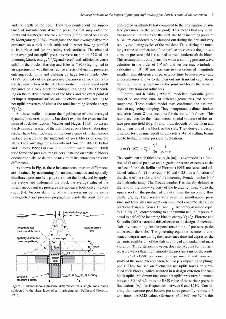
As shown in Fig. 6, these instantaneous pressure differencesare obtained by accounting for an instantaneous and spatiallydistributed pressure field pover(x, t) over the block, and by apply-ing everywhere underneath the block the average value of theinstantaneous surface pressures that appear at both joint entrances(punder(t)). Viscous damping of the pressures inside the jointsis neglected and pressure propagation inside the joint may be
Figure 6 Instantaneous pressure differences on a single rock blocksubjected to the shear layer of an impinging jet (Bellin and Fiorotto,1995).
considered as infinitely fast compared to the propagation of sur-face pressures (in the plunge pool). This means that any initialtransient oscillations inside the joint, due to an incoming pressurepulse, are considered to be damped out during the first and veryrapidly oscillating cycles of the transient. Thus, during the muchlonger time of application of the surface pressures at the joints, aconstant pressure field is assumed to install underneath the block.This assumption is only plausible when assuming pressure wavecelerities in the order of 103 m/s and surface macro-turbulentvelocities of 100–101 m/s, i.e. one to two orders of magnitudesmaller. This difference in persistence time between over- andunderpressures allows to dampen out any transient oscillationsthat might initially exist inside the joint and forms the basis toneglect any transient influences.
Fiorotto and Rinaldo (1992a,b) modelled hydraulic jumpimpact on concrete slabs of different geometries and bottomroughness. These scaled model tests confirmed the assump-tions of neglecting damping. They incorporated a dimensionlessreduction factor that accounts for the net uplift forces. Thisfactor accounts for the instantaneous spatial structure of the sur-face pressure field (Fig. 6) and, thus, depends on the form andthe dimensions of the block or the slab. They derived a designcriterion for dynamic uplift of concrete slabs of stilling basinsdue to hydraulic jump pressure fluctuations:
s = · (C+p + C−
p ) · V2j
2g· γ
γs − γ(7)
The equivalent slab thickness, s (in [m]), is expressed as a func-tion of and of positive and negative pressure extremes at thesurface of the slab. Bellin and Fiorotto (1995) measured and val-idated values for (between 0.10 and 0.25), as a function ofthe shape of the slabs and of the incoming Froude number F ofthe hydraulic jump. The Froude number F is thereby defined asthe ratio of the inflow velocity of the hydraulic jump, Vi, to thesquare root of the product of gravity times the incoming flowdepth,
√g · hi. Their results were based on simultaneous pres-
sure and force measurements on simulated concrete slabs. Forpractical design purposes, C+
p and C−p are safely assumed equal
to 1 in Eq. (7), corresponding to a maximum net uplift pressureequal to half of the incoming kinetic energy V2
j /2g. Fiorotto andSalandin (2000) extended this criterion to the design of anchoredslabs by accounting for the persistence time of pressure peaksunderneath the slabs. The governing equation assumes a con-stant underpressure during the persistence time and expresses thedynamic equilibrium of the slab as a forced and undamped massvibration. This criterion, however, does not account for transientpressure waves that might amplify the pressures inside the joints.
Liu et al. (1998) performed an experimental and numericalstudy of the same phenomenon, but for jets impacting in plungepools. They focused on fluctuating net uplift forces on simu-lated rock blocks, which resulted in a design criterion for rockblock uplift. Maximum measured net uplift pressures fluctuatedbetween 2.2 and 4.2 times the RMS value of the surface pressurefluctuations (σs), for frequencies between 0 and 12 Hz. Consid-ering that extreme pool bottom pressures generally represent 3to 4 times the RMS values (Ervine et al., 1997, see §2.4), this

10 Erik Bollaert and Anton Schleiss
results in a net uplift pressure equal to 0.55 to 1.05 times theincoming kinetic energy. The upper bound of net uplift pressureswas thereby systematically obtained for very small plunge poolwater depths, for which the jet directly impacts one of the joints ofthe simulated rock block. Developed jet impact generated upliftpressures close to the lower bound of 0.55. The scale of the rockblocks, on the order of 10−1 m, and the low pressure acquisitionrates (<200 Hz) did not allow generation and measurement ofshort-lived transient effects inside the joints.
Jia et al. (2001) presented a numerical model that calculatesthe uplift forces on granular loose-bed material due to planeimpinging jets. The mechanism of uplift was empirically intro-duced and calibrated based on Hoffmans’modification of Eq. (6).The obtained relationship between the surface pressure fluctu-ations and the net fluctuating uplift is in agreement with thefindings of Liu et al. (1998). They pointed out the need for fur-ther research in order to improve the understanding of the exactphysical mechanism of uplift.
The assumption of infinitely high pressure wave celerities,which results in no transient wave effects inside the joints, isonly acceptable if the impacting jet contains no frequencies thatmight be able to stimulate the underlying joints to oscillationsand/or resonance pressure waves. Assuming that the resonancefrequency fres of an open end joint underneath a slab or a block isdefined as c/2 ·L (open end resonator system, c is the wave celer-ity and L is the joint length), and assuming jet impact frequenciesless than 10 Hz, classical wave celerities of about 1000 m/s wouldbe able to stimulate the joints to oscillating and resonance con-ditions if the joint length L were on the order of 102 m (Fiorottoand Rinaldo, 1992b). Such joint lengths are out of the realm ofpractical engineering.
For this reason, existing scour evaluation methods deal withnet uplift forces in a sort of steady-state differential manner,whereby the underpressures are assumed constant and deter-mined by the surface pressures entering the joints. By neglectingany possible pressures over the surface of the blocks or the slabs,this results in maximum net uplift forces that are equal to thekinetic energy head of the incoming jet.
3 Theoretical framework for a multiphase transientscour evaluation method
Two statements contradict the above assumption. First, free airthat is present in the water may largely decrease the pressure wavecelerity and the theoretical resonance frequency of a joint. A veryslight change in free air content drastically changes the gas–liquid compressibility and, thus, the corresponding wave celerity.Assuming that an aerated water jet generates air entrainment inrock joints, it seems plausible to account for a reduced wave celer-ity of the air–water mixture inside the joints. For a free air concen-tration of 1% and a pressure wave celerity of 200 m/s, resonanceeffects might be generated inside the joints for joint lengths L ofonly O (101) m, i.e. a realistic value. Second, it has been empha-sized that prototype-scaled turbulent shear flows may containnon-negligible spectral energy at high frequencies (>10 Hz),especially in the case of high-velocity jet impact (Fig. 5).
Therefore, for prototype jet or hydraulic jump impact in plungepools, it is believed that transient wave effects inside joints mightsignificantly influence net uplift forces on slabs or rock blocks andthat they constitute a potential key to a physically more appro-priate modelling of rock scour or dynamic slab uplift. Such atransient approach seems hazardous due to the complex natureof jointed rock and due to the unknown characteristics of pressurewaves travelling inside the joints. It is obvious that the analysis ofthe problem requires a fully transient computation, able to repro-duce violent transient two-phase phenomena. Their relevance fordesign purposes is developed in Part II of the paper.
Direct application of fully transient theory on pressure wavesinside rock joints is not available in literature. Kirschke (1974)numerically studied the propagation of water hammer waves inone-dimensional fine discontinuities of rigid, elastic or plasticrock media, but only for steady pressures at the joint entry. Fur-thermore, very little is known on the influence of air on dynamicpressures in joints, which is a further key element for any fullytransient analysis inside the rock matrix. Transient flow theory, onthe contrary, is well developed in the fields of pressure surges inpipelines and acoustics. Numerical techniques are available thataccount for phenomena such as resonance and damping, aerationand cavitation, etc.
To fill up this lack of knowledge, model tests on differentrock joint geometries have been carried out at the Laboratory ofHydraulic Constructions of the Swiss Federal Institute of Tech-nology in Lausanne (LCH-EPFL). The purpose of the tests wasto verify whether highly transient pressure wave phenomena areof influence on the process of progressive break-up of rock jointsby hydrodynamic jacking and on the process of dynamic upliftof rock blocks (or concrete slabs) by net uplift pressures. Theexperiments focused on pressure fluctuations inside simulatedrock joints under the impact of aerated high velocity jets. Thevelocity of the jets is at prototype scale (up to 35 m/s), in order toobtain realistic aeration rates and turbulence spectra. Both two-and one-dimensional rock joints have been simulated, with open(= single rock block) or closed (= fractured rock mass) endboundaries. Pressures have been measured simultaneously at thepool bottom and inside the joints, at a data acquisition rate of upto 20 kHz, in order to detect any transient phenomena.
The experimental results reveal considerable jet energy inintermediate and high frequency ranges (up to 50–100 Hz) andsignificant pressure amplification inside 1D joints, even for veryshort joint lengths (less than 1 m). Very low wave celeritieshave been observed (<50–100 m/s), due to significant aerationinside the joints. Peak pressures in the joints amplified up to 5–6times the corresponding maximum pressure at the pool bottom(Bollaert and Schleiss, 2001a; Bollaert, 2002). Test results arediscussed in detail in Part II of this paper.
4 Conclusion and future research
Knowledge on the interaction between dynamic pressure fluc-tuations at a plunge pool bottom and fully transient pressurewave propagation in rock joints is actually lacking. Hence,
Scour of rock due to the impact of plunging high velocity jets Part I: A state-of-the-art review 11
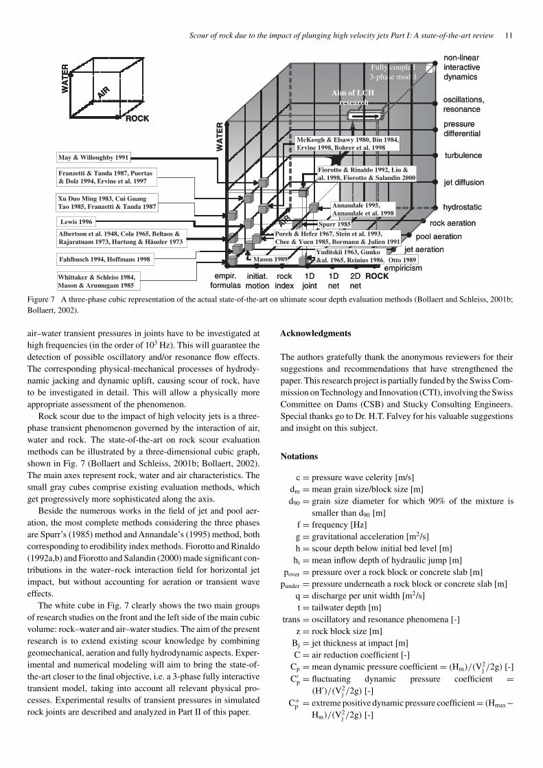
Figure 7 A three-phase cubic representation of the actual state-of-the-art on ultimate scour depth evaluation methods (Bollaert and Schleiss, 2001b;Bollaert, 2002).
air–water transient pressures in joints have to be investigated athigh frequencies (in the order of 103 Hz). This will guarantee thedetection of possible oscillatory and/or resonance flow effects.The corresponding physical-mechanical processes of hydrody-namic jacking and dynamic uplift, causing scour of rock, haveto be investigated in detail. This will allow a physically moreappropriate assessment of the phenomenon.
Rock scour due to the impact of high velocity jets is a three-phase transient phenomenon governed by the interaction of air,water and rock. The state-of-the-art on rock scour evaluationmethods can be illustrated by a three-dimensional cubic graph,shown in Fig. 7 (Bollaert and Schleiss, 2001b; Bollaert, 2002).The main axes represent rock, water and air characteristics. Thesmall gray cubes comprise existing evaluation methods, whichget progressively more sophisticated along the axis.
Beside the numerous works in the field of jet and pool aer-ation, the most complete methods considering the three phasesare Spurr’s (1985) method and Annandale’s (1995) method, bothcorresponding to erodibility index methods. Fiorotto and Rinaldo(1992a,b) and Fiorotto and Salandin (2000) made significant con-tributions in the water–rock interaction field for horizontal jetimpact, but without accounting for aeration or transient waveeffects.
The white cube in Fig. 7 clearly shows the two main groupsof research studies on the front and the left side of the main cubicvolume: rock–water and air–water studies. The aim of the presentresearch is to extend existing scour knowledge by combininggeomechanical, aeration and fully hydrodynamic aspects. Exper-imental and numerical modeling will aim to bring the state-of-the-art closer to the final objective, i.e. a 3-phase fully interactivetransient model, taking into account all relevant physical pro-cesses. Experimental results of transient pressures in simulatedrock joints are described and analyzed in Part II of this paper.
Acknowledgments
The authors gratefully thank the anonymous reviewers for theirsuggestions and recommendations that have strengthened thepaper. This research project is partially funded by the Swiss Com-mission on Technology and Innovation (CTI), involving the SwissCommittee on Dams (CSB) and Stucky Consulting Engineers.Special thanks go to Dr. H.T. Falvey for his valuable suggestionsand insight on this subject.
Notations
c = pressure wave celerity [m/s]dm = mean grain size/block size [m]d90 = grain size diameter for which 90% of the mixture is
smaller than d90 [m]f = frequency [Hz]g = gravitational acceleration [m2/s]h = scour depth below initial bed level [m]hi = mean inflow depth of hydraulic jump [m]
pover = pressure over a rock block or concrete slab [m]punder = pressure underneath a rock block or concrete slab [m]
q = discharge per unit width [m2/s]t = tailwater depth [m]
trans = oscillatory and resonance phenomena [-]z = rock block size [m]
Bj = jet thickness at impact [m]C = air reduction coefficient [-]
Cp = mean dynamic pressure coefficient = (Hm)/(V2j /2g) [-]
C′p = fluctuating dynamic pressure coefficient =
(H′)/(V2j /2g) [-]
C+p = extreme positive dynamic pressure coefficient = (Hmax−
Hm)/(V2j /2g) [-]

12 Erik Bollaert and Anton Schleiss
C−p = extreme negative dynamic pressure coefficient = (Hm −
Hmin)/(V2j /2g) [-]
Dj = jet diameter at impact [m]F = incoming Froude number of hydraulic jump [-]
Sxx(f) = power spectral content of pressure fluctuations [m2]H = jet fall height [m]H′ = RMS value of dynamic pressure fluctuations [m]
Hm = mean dynamic pressure head [m]Hmax = maximum dynamic pressure head [m]Hmin = minimum dynamic pressure head [m]
K = parameter for empirical scour formulae (Eqs. (1) and (4))[-]
Kc = parameter to express the jet core length Lc [-]L = jet fall length or rock joint length [m]
Lb = jet break-up length [m]Lc = jet core length [m]Nj = number of joint sets [-]Qa = air discharge [m3/s]Qw = water discharge [m3/s]
RMS = Root-mean-square value of pressure fluctuations [m]RQD = Rock Quality Designation [%]
Tu = initial jet turbulence intensity [%]Vair = minimum air entrainment velocity [m/s]
Vi = mean inflow velocity of hydraulic jump [m/s]Vj = mean jet velocity at impact [m/s]Y = t + h, total plunge pool depth [m]αj = dip angle of joint set j [◦]β = volumetric air-to-water ratio = Qa/Qw [-]φ = angle of repose of bed material [◦]
φj = residual friction angle of joint set j [◦]ω = mean particle fall velocity [m/s]γ = water specific weight [N/m3]γs = particle/rock specific weight [N/m3]θ = impact angle of the jet with the horizontal [◦]
σc = uniaxial compressive strength [N/m2]σs = RMS of surface pressure fluctuations [m]σt = uniaxial tensile strength [N/m2]σu = RMS value of underpressure fluctuations [m]� = (ρs − ρ)/ρ = γs/γ − 1 = relative density [-]
References
1. Annandale, G.W. (1995). “Erodibility,” J. Hydr. Res.,33(4), 471–494.
2. Annandale, G.W., Wittler, R.J., Ruff, J.F. and Lewis,T.M. (1998). Prototype Validation of Erodibility Indexfor Scour in Fractured Rock Media, ASCE, Proceedingsof the 1998 International Water Resources EngineeringConference, Memphis, Tennessee.
3. Ballio, F., Franzetti, S. and Tanda, M.G. (1994).“Pressure Fluctuations Induced by Turbulent Circular JetsImpinging on a Flat Plate,” Excerpta, 7, 41–59.
4. Bearman, P.W. (1972). “An Investigation of the Forces onFlat Plates Normal to a Turbulent Flow,” J. Fluid Mech., 46,177–198.
5. Bellin,A. and Fiorotto, V. (1995). “Direct Dynamic ForceMeasurement on Slabs in Spillway Stilling Basins,” ASCE,J. Hydr. Engrg., 121(10), 686–693.
6. Beltaos, S. (1976). “Oblique Impingement of CircularTurbulent Jets,” J. Hydr. Res., 14(1), 17–36.
7. Beltaos, S. and Rajaratnam, N. (1973). “Plane TurbulentImpinging Jets,” J. Hydr. Res., 1(1), 29–59.
8. Beltaos, S. and Rajaratnam, N. (1974). “Impinging Cir-cular Turbulent Jets,” J. Hydr. Div., ASCE, 100(HY10),1313–1328.
9. Bieniawski, Z.T. (1984). Rock Mechanics Design in Min-ing and Tunnelling, A.A. Balkema, Rotterdam, pp. 97–133.
10. Bin, A.K. (1984). Air Entrainment by Plunging Liquid Jets,Proceedings of the IAHR Symposium on Scale Effects inModeling Hydraulic Structures, paper no. 5.5, Esslingen.
11. Blaisdell, F.W. and Anderson, C.L. (1981). “Ulti-mate Dimensions of Local Scour,” ASCE, J. Hydr. Div.,107(HY3), 327–337.
12. Bohrer, J.G. and Abt, S.R. (1997). “Dam Foundation Ero-sion: Behavior of a Free-trajectory Jet in a Plunge Basin,”Proceedings of the 27th IAHR Congress, D, 435–440.
13. Bohrer, J.G., Abt, S.R. and Wittler, R.J. (1998).“Predicting Plunge Pool Velocity Decay of Free Falling,Rectangular Jet,” J. Hydr. Engrg., ASCE, 124(10), 1043–1048.
14. Bollaert, E. (2001). Spectral Density Modulation ofPlunge Pool Bottom Pressures Inside Rock Fissures, Pro-ceedings of the XXIXth IAHR Congress, Student PaperCompetition, Beijing, September 2001.
15. Bollaert, E. (2002). Transient water pressures in jointsand formation of rock scour due to high-velocity jet impact,Communication No. 13, Laboratory of Hydraulic Construc-tions, EPFL, Switzerland.
16. Bollaert, E. and Schleiss, A. (2001a). Air Bubble Effectson Transient Water Pressures in Rock Fissures due toHigh Velocity Jet Impact, Proceedings of the XXIXth IAHRCongress, Beijing, September 2001.
17. Bollaert, E. and Schleiss, A. (2001b). A New Approachfor betterAssessment of Rock Scouring due to HighVelocityJets at Dam Spillways, Proceedings of the ICOLD EuropeanSymposium, Geiranger Norway, June 2001.
18. Bormann, E. and Julien, P.Y. (1991). “Scour Down-stream of Grade-control Structures,” J. Hydr. Engrg., ASCE,117(5), 579–594.
19. Breusers, H.N.C. (1963). “Discussion of Sediment Trans-port Mechanics: Erosion of Sediment,” J. Hydr. Div. ASCE,89(HY1).
20. Brighetti, G. (1975). Etude sur Modèle Réduit de l’Erosiondu Lit Rocheux en Aval d’un Déversoir en Saut de ski, Pro-ceedings of the 16th IAHR Congress, Sao Paulo, 2(B55), pp.439–447.
21. Chee, S.P. and KUNG, T. (1971). “Stable Profiles of PlungeBasins,” J. American Water Res. Assoc., 7(2), 303–308.
22. Chee, S.P. and Yuen, E.M. (1985). “Erosion of Uncon-solidated Gravel Beds,” Canadian J. Civil Engrg., 12,559–566.
Scour of rock due to the impact of plunging high velocity jets Part I: A state-of-the-art review 13
23. Cola, R. (1965). Energy Dissipation of a High-VelocityVertical Jet entering a Basin, Proceedings of the 11th IAHRCongress, Leningrad.
24. Cui, G.T., Lin, Y. and Liang, X. (1985). Efeito doImpacto, no Leito do Rio, da Lamina descarregada sobreuma Barragem-abobada, Translation from Chinese by Pintode Campos in 1986, Beijing, pp. 58–63.
25. Doddiah, D., Albertson, M.L. and Thomas, R. (1953).Scour from Jets, Proceedings of the Minnesota InternationalHydraulics Conference, pp. 161–169.
26. Ervine, D.A. (1976). “The Entrainment of Air in Water,”International Water Power and Dam Construction, 28(12),27–30.
27. Ervine, D.A. (1998). “Air Entrainment in Hydraulic Struc-tures: a Review,” Proceedings of the of the Institution ofCivil Engineers, Water, Marit. And Energy, 130, 142–153.
28. Ervine, D.A. and Falvey, H.T. (1987). Behavior of Tur-bulent Water Jets in the Atmosphere and in Plunge Pools,Proceedings of the Institution of Civil Engineers, Part 2, pp.295–314.
29. Ervine, D.A., Falvey, H.T. and Withers, W. (1997).“Pressure Fluctuations on Plunge Pool Floors,” J. Hydr. Res.,35(2), 257–279.
30. Fahlbusch, F.E. (1994). “Scour in Rock Riverbeds Down-stream of Large Dams,” Hydropower & Dams, 1(4), 30–32.
31. Fiorotto, V. and Rinaldo, A. (1992a). “Turbulent PressureFluctuations under Hydraulic Jumps,” J. Hydr. Res., 30(4),499–520.
32. Fiorotto, V. and Rinaldo, A. (1992b). “Fluctuating Upliftand Lining Design in Spillway Stilling Basins,” J. Hydr.Engrg., ASCE, 118(HY4), 578–596.
33. Fiorotto, V. and Salandin, P. (2000). “Design ofAnchored Slabs in Spillway Stilling Basins,” J. Hydr.Engrg., ASCE, 126(7), 502–512.
34. Franzetti, S. and Tanda, M.G. (1987). “Analysis of Tur-bulent Pressure Fluctuation Caused by a Circular ImpingingJet,” International Symposium on New Technology in ModelTesting in Hydraulic Research, India, pp. 85–91.
35. Gerodetti, M. (1982). Auskolkung eines felsigen Fluss-bettes (Modellversuche mit bindigen Materialen zur Sim-ulation des Felsens). Arbeitsheft No. 5, VAW, ETHZ,Zürich.
36. Gunko, F.G., Burkov, A.F., Isachenko, N.B.,Rubinstein, G.L., Soloviova, A.G. and Yuditskii, G.A.(1965). “Research on the Hydraulic Regime and Local Scourof River Bed below Spillways of High-head Dams,” Pro-ceedings of the 11th IAHR Congress, Leningrad, 1(50),1–14.
37. Hartung, F. and Häusler, E. (1973). “Scours, StillingBasins and Downstream Protection under free Overfall Jetsat Dams,” Proceedings of the 11th Congress on Large Dams,Madrid, Vol. II, Q.41, Paper R3, pp. 39–56.
38. Hoffmans, G.J.C.M. (1998). “Jet Scour in EquilibriumPhase,” ASCE, J. Hydr. Engrg., 124(4), 430–437.
39. Hoffmans, G.J.C.M. and Verheij, H.J. (1997). ScourManual, Balkema, Rotterdam, The Netherlands.
40. Homma, M. (1953). An Experimental Study on Water Fall,Proceedings of the Minnesota Int. Hydraulics Conference,USA.
41. Huot, J.P., Rey, C. and Arbey, H. (1986). “ExperimentalAnalysis of the Pressure Field induced on a Square Cylinderby a Turbulent Flow,” J. Fluid Mech., 162, 283–298.
42. Jia, Y., Kitamura, T. and Wang, S.S.Y. (2001). “Sim-ulation of Scour Process in Plunging Pool of Loose Bed-material,” ASCE, J. Hydr. Engrg., 127(3), 219–229.
43. Johnson, G. (1967). The effect of entrained air in the scour-ing capacity of water jets, Proceedings of the 12th Congressof the IAHR, Vol. 3, Fort Collins.
44. Johnson, G. (1977). Use of a weakly cohesive material forscale model scour tests in flood spillway design, Proceedingsof the 17th Congress of the IAHR, Vol. 4, Baden–Baden.
45. Kirschke, D. (1974). Druckstossvorgänge in Wassergefüll-ten Felsklüften, Veröffentlichungen des Institut für Bodenund Felsmechanik, Dissertation, Universität Karlsruhe.
46. Kolmogoroff, A.N. (1941). “The Local Structure of Tur-bulence in Incompressible Viscous Fluid for Very LargeReynolds Numbers,” C.R. Acad. Sci., U.R.S.S., 30–301.
47. Lewis, T., Abt, S.R., Wittler, R.J. and Annandale, G.W.(1996). Predicting ImpactVelocities of Developed Jets, DamFoundation Erosion Study, Internal Report, Colorado.
48. Liu, P.Q. (1999). Mechanism of Energy Dissipation andHydraulic Design for Plunge Pools Downstream of LargeDams, China Institute of Water Resources and HydropowerResearch, Beijing, China.
49. Liu, P.Q., Dong, J.R. and Yu, C. (1998). “ExperimentalInvestigation of Fluctuating Uplift on Rock Blocks at theBottom of the Scour Pool Downstream of Three-GorgesSpillway,” J. Hydr. Res., 36(1), 55–68.
50. Machado, L.I. (1982). O Sistema de Dissipacao de EnergiaProposto para a Barragem de Xingo, Transactions of theInternational Symposium on the Layout of Dams in NarrowGorges, ICOLD, Brazil.
51. Martins, R. (1973). Contribution to the knowledge on thescour action of free jets on rocky river beds, Proceedings ofthe 11th Congress on Large Dams, Madrid, pp. 799–814.
52. Mason, P.J. (1983). Energy dissipating crest splitters forconcrete dams, Water Power and Dam Construction, pp.37–40.
53. Mason, P.J. (1989). “Effects of Air Entrainment on PlungePool Scour,” J. Hydr. Engrg., ASCE, 115(3), 385–399.
54. Mason, P.J. and Arumugam, K. (1985). “Free Jet Scourbelow Dams and Flip Buckets,” J. Hydr. Engrg., 111(2),220–235.
55. May, R.W.P. and Willoughby, I.R. (1991). Impact Pres-sures in Plunge Pool Basins due to Vertical Falling Jets,Report SR 242, HR Wallingford, UK.
56. McKeogh, E.J. and Elsawy, E.M. (1980). “Air Retainedin Pool by Plunging Water Jet,” ASCE, J. Hydr. Div.,106(HY10), 1577–1593.
57. Mih, W. and Kabir, J. (1983). “Impingement of Water Jetson Nonuniform Streambed,” ASCE, J. Hydr. Engrg., 109(4),536–549.
14 Erik Bollaert and Anton Schleiss
58. Mirtskhulava, T.E., Dolidze, I.V. and Magomeda, A.V.(1967). Mechanism and computation of local and generalscour in non cohesive, cohesive soils and rock beds, Pro-ceedings of the 12th IAHR Congress, Vol. 3, Fort Collins,pp. 169–176.
59. Montgomery, R. (1984). Investigations into Rock Erosionby HighVelocity Water Flows, M.Sc. Thesis, Royal Instituteof Technology Sweden, Stockholm.
60. Otto, B. (1989). Scour Potential of Highly StressedSheet-jointed Rocks under obliquely Impinging Plane Jets,Thesis submitted to the James Cook University of NorthQueensland, Townsville.
61. Poreh, M. and Hefez, E. (1967). Initial Scour and SedimentMotion due to an Impinging Submerged Jet, Proceedings ofthe 12th IAHR Congress, paper C2, Fort Collins, Colorado,United States.
62. Puertas, J. and Dolz, J. (1994). Criterios Hidrauli-cos para el diseno de cuencos de disipacion de ener-gia en presas boveda con vertido libre por coronacion,PhD Thesis summary, University of Catalunya, Barcelona,Spain.
63. Quintela, A.C. and Da Cruz, A.A. (1982). Cabora-Bassadam spillway, conception, hydraulic model studies andprototype behaviour, Transactions of the International Sym-posium on the Layout of Dams in Narrow Gorges, ICOLD,Brazil.
64. Ramos, C.M. (1982). Energy dissipation on free jet spill-ways. Bases for its study in hydraulic models, Transactionsof the International Symposium on the Layout of Dams inNarrow Gorges, ICOLD, Rio de Janeiro, Brazil, Vol. 1, pp.263–268.
65. Rehbinder, G. (1980). A theory about cutting rock with awater jet, Rock Mechanics (Springer Verlag) Vol. 12, pp.247–257.
66. Reinius, E. (1986). “Rock Erosion,” International WaterPower and Dam Construction, 38(6), 43–48.
67. Rubinstein, G.L. (1963). Laboratory investigation of localerosion on channel beds below high overflow dams, Transac-tions of Coordination Conferences on Hydraulic Engineer-
ing. Iss. VII, Conference on Hydraulics of High Head WaterDischarge Structures. Gosenergoizdat M.L.
68. Simons, D.B. and Stevens, N.A. (1971). Chapter 24: ScourControl in Rock basins at Culvert Outlets, River Mechanics,Vol. 2, H.W. Shen, ed., 24-1–24-62.
69. Spurr, K.J.W. (1985). “Energy Approach to EstimatingScour Downstream of a Large Dam,” Water Power and DamConstruction 37(11), 81–89.
70. Stein, O.R., Julien, P.Y. and Alonso, C.V. (1993).“Mechanics of Jet Scour Downstream of a Headcut,” J. Hydr.Res., 31(6), 723–738.
71. Toso, J.W. and Bowers, C.E. (1988). “Extreme Pressuresin Hydraulic Jump Stilling Basins,” ASCE, J. Hydr. Engrg.,114(8), 829–843.
72. Veronese, A. (1937). Erosion of a bed downstream froman outlet, Colorado A & M College, Fort Collins, UnitedStates.
73. Vischer, D.L. and Hager, W.H. (1995). Energy Dissi-pators, IAHR Hydraulic Structures Design Manual, AABalkema, Rotterdam, The Netherlands.
74. Whittaker, J. and Schleiss, A. (1984). “Scour Related toEnergy Dissipators for High Head Structures,” Mitteilun-gen der Versuchsanstalt für Wasserbau, Hydrologie undGlaziologie, N°73, VAW, ETH Zürich.
75. Wittler, R.J., Abt, S.R., Ruff, J.F. andAnnandale, G.W.(1997). Dam Foundation Erosion: Pit 4 Dam Scale and Pro-totype Model Tests Results and Comparison, Proceedingsof the 27th IAHR Congress, pp. 441–446.
76. Xu Duo Ming and Yu Chang Zhao (1983). PressãoNo Fundo de um Canal Devido ao Choque de um JactoPlano, e suas Caracterìsticas de Flutuação, Translation fromChinese to Portuguese by Pinto de Campos, Beijing (5),pp. 52–58.
77. Yuditskii, G.A. (1963). Action of Falling Jet on JointBlocks of a Rock and Conditions of Its Erosion, IzvestiyaVNIIG, Vol. 7, pp. 35–60.
78. Yuditskii, G.A. (1971). Experimental Prediction of RockBed Scour below a Ski-jump Spillway Dam, Translationfrom Russian by the IPST, Jerusalem.