Embed Size (px)
Citation preview

SD HTPC User ManualFebruary 17th, 2016
Revision 2.2(Latest revision of this manual is available for download on our website at
www.steigerdynamics.com/support-downloads )
COPYRIGHT © 2012-2016 STEIGER DYNAMICS LLC. ALL RIGHTS RESERVED.
SD Living Room PC User Manual – Revision 2.2
Welcome
Dear Customer:
Thank you for purchasing a hand-assembled, custom-made living room PCfrom STEIGER DYNAMICS.
It is our pleasure to welcome you to our exclusive community of customers.We hope you will have years of you joy and high-performance computingwith your new system.
Each one of our living room PCs is designed and assembled in the UnitedStates and supported in-house by the very engineer who created it.
Your system was manufactured to your specifications with your needs inmind, and we are confident that you are going to love it as much as we didmanufacturing it.
We know you are extremely excited to get started right away, but it isvery important that you read the following “Quick-Start-Guide” toassure a hassle-free setup and an ideal user experience.
Please pay special attention to the items that are marked with this icon:
Kind regards,
Martin Gossner
CEO
2
SD Living Room PC User Manual – Revision 2.2
Table of Content
3
I. Quick-Start-Guide 4
Step 1 – Unpacking & Hardware Check 4
Step 2 – Intro to System Buttons & Connectors 5
Step 3 – System Placement Considerations 6
Step 4 – Connecting the System 7
Step 5 – Connecting the Peripherals 9
Step 6 – Ready to Roll 9
IV. Manufacturing Log 17
1. BIOS, Drivers, and Windows Software & Settings 13
2. Software & Apps 14
3. Backup & Restore 15
4. Hardware 16
Phase 1 – Preparation 17
Phase 2 – Initial Software Installation 17
Phase 3 – Final Hardware Assembly & Software Installation 17
Phase 4 – Final Tests 18
Phase 5 – Finishing 18
III. Best Practices 13
II. DIY Builder Guide 10
1. Hardware Assembly 10
2. Software Setup 12
SD Living Room PC User Manual – Revision 2.2
I. Quick-Start-Guide (1/6)
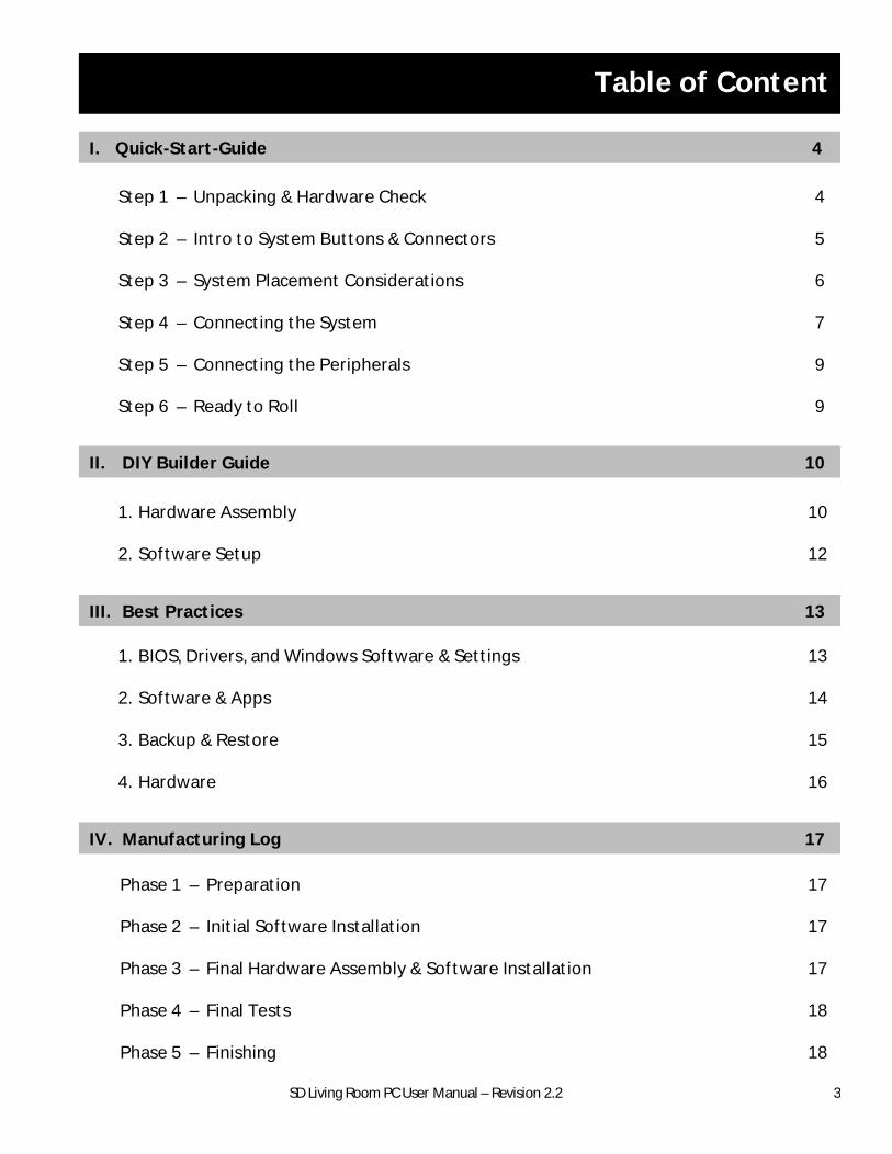
Please call us (1-855-915-9000) or email us ([email protected]), if anything is damaged or missing.
Please keep all original packaging material incl. interior Instapak foam for potential warranty shipment!
4
C. Check accessories
§ Power cable
§ HDMI Cable (standard with LEET)
§ Wifi Antennas (Standard with LEET)
§ Black STEIGER DYNAMICS Box with spare parts
§ Black STEIGER DYNAMICS Binder with disks
A. Unpack your system
Step 1 – Unpacking & Hardware Check
4. Reattach lid
5. Reattach lid screws
3. Remove foam and check connections
§ Check cable connections
§ Check that PCI cards are in place
1. Remove lid screws
§ The 2 thumb screws on rear side of chassis are easily unfastened by hand
2. Remove Lid
§ Lift up back of lid by approx. 1 inch
§ Pull lid back and out of bracket
D. Check peripherals
§ Other peripherals you have ordered
Peripherals might be drop shipped and arrive separately from your system.
B. Optional: Inspect system for external internal damage/flaws
HDD cables
GPU cables
GPU
Other
PCI-E
1. Unpack outer box
§ Cut outer box open on top and unfold cover
§ Flip outer box up side down
§ Lift off outer box (inner box will be up side down)
2. Unpack inner box
§ Cut inner box open on bottom and unfold cover
§ Flip box up side up
§ Lift off inner box to reveal system
SSD cables
(NOTE: Your configuration may vary!)
SD Living Room PC User Manual – Revision 2.2
I. Quick-Start-Guide (2/6)
5
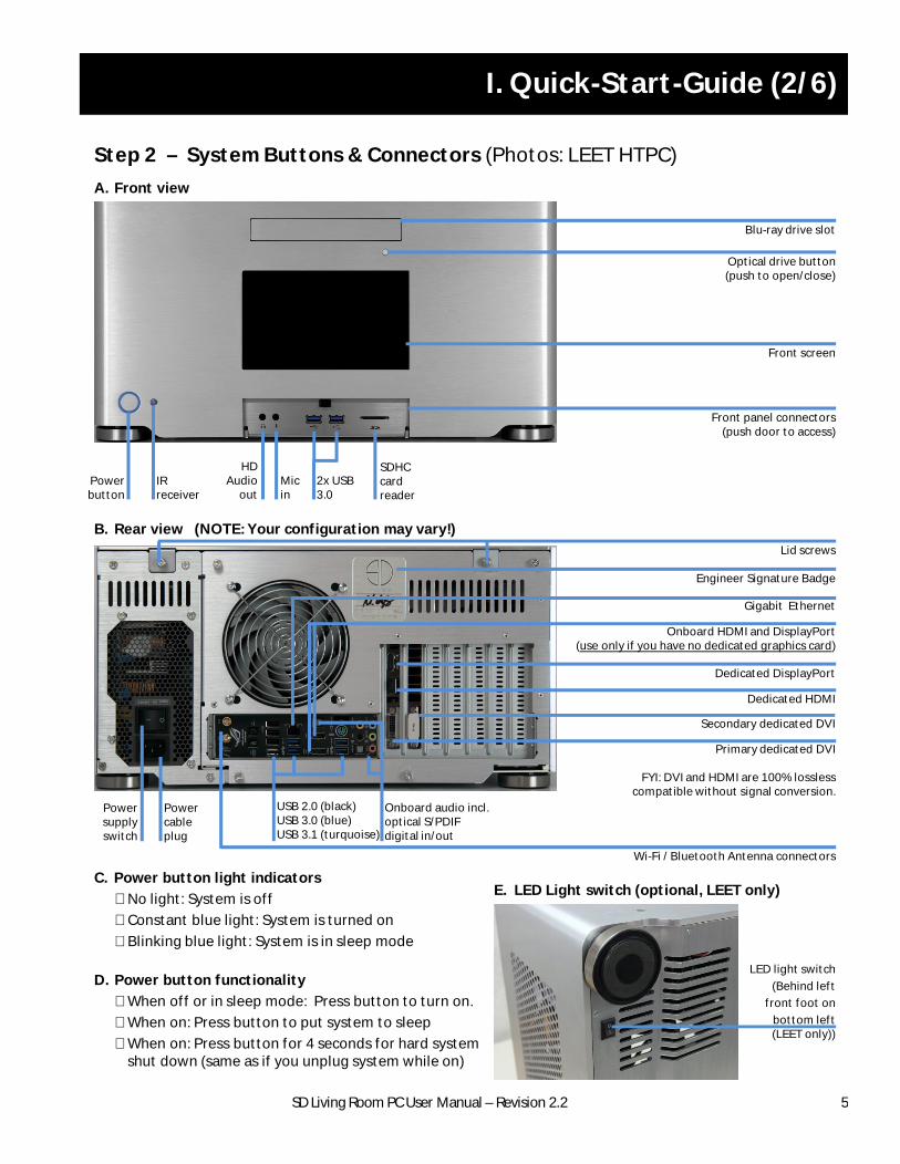
Step 2 – System Buttons & Connectors (Photos: LEET HTPC)
Blu-ray drive slot
Optical drive button(push to open/close)
Front screen
Front panel connectors(push door to access)
HD Audio
outMicin
2x USB3.0
SDHCcard reader
Power button
A. Front view
B. Rear view
IR receiver
Power supply switch
Power cable plug
USB 2.0 (black)USB 3.0 (blue)USB 3.1 (turquoise)
Onboard audio incl. optical S/PDIF digital in/out
Lid screws
Engineer Signature Badge
Primary dedicated DVI
FYI: DVI and HDMI are 100% losslesscompatible without signal conversion.
Dedicated HDMI
Dedicated DisplayPort
Secondary dedicated DVI
Onboard HDMI and DisplayPort(use only if you have no dedicated graphics card)
Gigabit Ethernet
(NOTE: Your configuration may vary!)
E. LED Light switch (optional, LEET only)
LED light switch
(Behind left
front foot on
bottom left (LEET only))
Wi-Fi / Bluetooth Antenna connectors
C. Power button light indicators
§ No light: System is off
§ Constant blue light: System is turned on
§ Blinking blue light: System is in sleep mode
D. Power button functionality
§ When off or in sleep mode: Press button to turn on.
§ When on: Press button to put system to sleep
§ When on: Press button for 4 seconds for hard system shut down (same as if you unplug system while on)
SD Living Room PC User Manual – Revision 2.2
I. Quick-Start-Guide (3/6)
6
High performance systems like the STEIGER DYNAMICS HTPCs require proper system placement to assure safe operating temperatures and solid system stability even under hours of heavy load. Please follow the instructions below.A. Optimize airflow
§ Ensure good air circulation and do not place into fully closed cabinets.
§ If you place your system in an AV-Rack or under/in a desk, ensure 2” (5 cm) air intake and exhaust clearance for the fans and ventilation holes on bottom, rear, and left side, and top.
§ Do not put system on carpet or soft surfacessince they block air intakes on the bottom.
B. Keep away from water, heat, and dust
§ Setup in dry area and avoid exposure to water/rain and excessive humidity.
§ Do not use system as a drink holder or coaster.
§ Avoid hot/warm areas like proximity to heaters.
§ Dust decreases system cooling performance, hence avoid dusty areas.
C. Keep accessible
Keep system accessible to do any of the following:
§ Gently clean system exterior and interior from dust
§ Turn on light switch
§ Open/close optical drive
§ Access front panel connectors
§ Access connectors on the back
D. Place IR receiver (opt.) in direct line of sight
§ Place system in a way so you can easily see the front screen for system monitoring parameters and entertainment information (LEET only)
§ The IR receiver on the front left needs to be in line of sight to use the IR remote control.
E. Other considerations
§ Never push objects into the PC. This could cause short circuits , liquid drain, shock and/or fire.
§ Keep juniors’ hands away.
§ Keep system away from strong magnetic fields.
§ The system weighs up to 70 pounds. To avoid injury, it should only be moved by a person with a respective fitness level.
Step 3 – System Placement Considerations
Keepclean
Keepdry
Keepcool
NoKids
Nomagnets
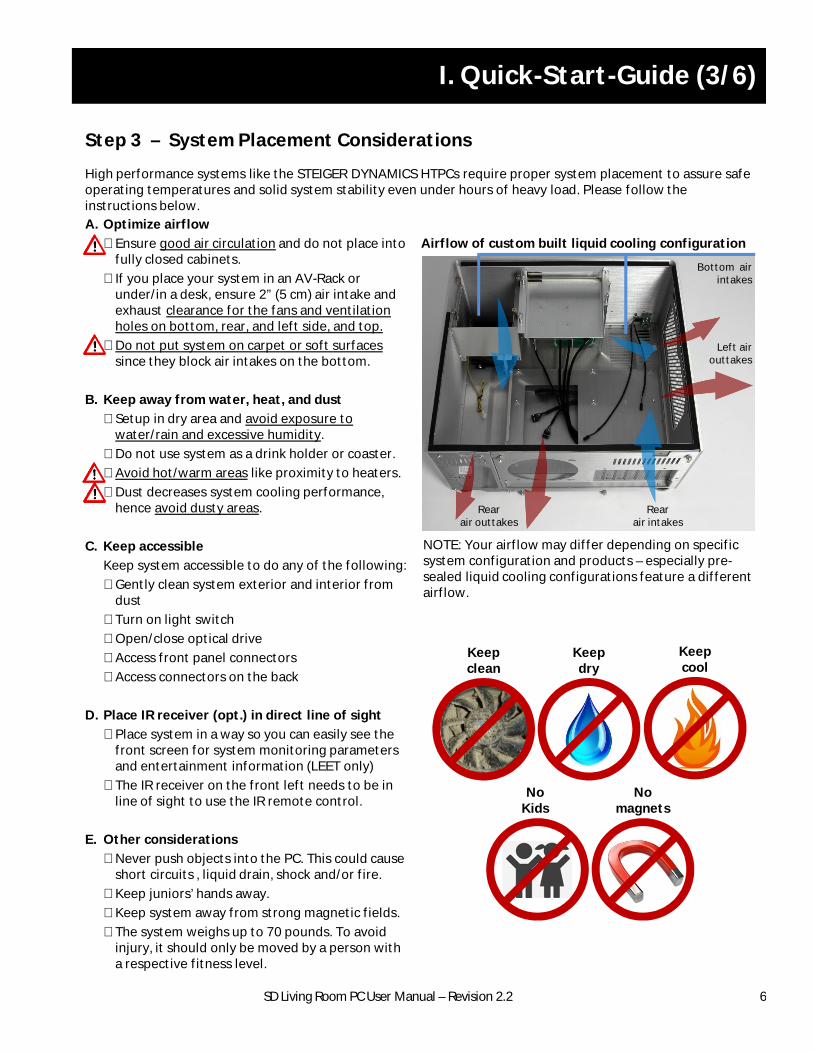
Rearair intakes
Rearair outtakes
Left airouttakes
Bottom airintakes
Airflow of custom built liquid cooling configuration
NOTE: Your airflow may differ depending on specific system configuration and products – especially pre-sealed liquid cooling configurations feature a different airflow.
SD Living Room PC User Manual – Revision 2.2
I. Quick-Start-Guide (4/6)
7
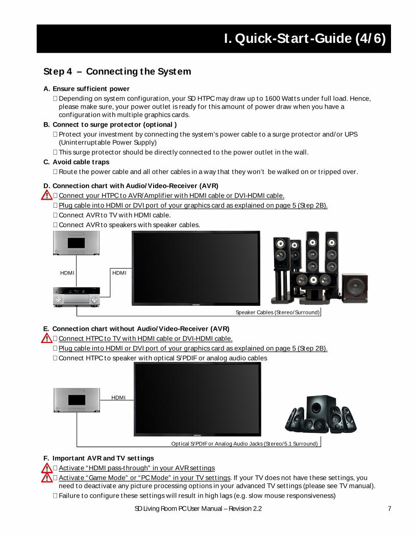
D. Connection chart with Audio/Video-Receiver (AVR)
§ Connect your HTPC to AVR/Amplifier with HDMI cable or DVI-HDMI cable.
§ Plug cable into HDMI or DVI port of your graphics card as explained on page 5 (Step 2B).
§ Connect AVR to TV with HDMI cable.
§ Connect AVR to speakers with speaker cables.
A. Ensure sufficient power
§ Depending on system configuration, your SD HTPC may draw up to 1600 Watts under full load. Hence, please make sure, your power outlet is ready for this amount of power draw when you have a configuration with multiple graphics cards.
B. Connect to surge protector (optional )
§ Protect your investment by connecting the system’s power cable to a surge protector and/or UPS (Uninterruptable Power Supply)
§ This surge protector should be directly connected to the power outlet in the wall.
C. Avoid cable traps
§ Route the power cable and all other cables in a way that they won’t be walked on or tripped over.
E. Connection chart without Audio/Video-Receiver (AVR)
§ Connect HTPC to TV with HDMI cable or DVI-HDMI cable.
§ Plug cable into HDMI or DVI port of your graphics card as explained on page 5 (Step 2B).
§ Connect HTPC to speaker with optical S/PDIF or analog audio cables
HDMI HDMI
Speaker Cables (Stereo/Surround)
HDMI
Optical S/PDIF or Analog Audio Jacks (Stereo/5.1 Surround)
Step 4 – Connecting the System
F. Important AVR and TV settings
§ Activate “HDMI pass-through” in your AVR settings
§ Activate “Game Mode” or “PC Mode” in your TV settings. If your TV does not have these settings, you need to deactivate any picture processing options in your advanced TV settings (please see TV manual).
§ Failure to configure these settings will result in high lags (e.g. slow mouse responsiveness)
SD Living Room PC User Manual – Revision 2.2
I. Quick-Start-Guide (5/6)
8
NOTE: When turning on your HTPC for the first time, it is recommended to connect the bare minimum peripherals, such as keyboard, mouse, and TV/monitor before connecting other devices like gamepads, Wi-Fi receivers, scanners, printers, headsets, external hard drives, etc. After initial setup, shut down your system and then connect your remaining devices.
A. Mouse and keyboard
§ Connect mouse and keyboard (or their respective wireless receivers if you have wireless devices) to the black USB 2.0 ports on the back of the system. Some of the motherboard I/O-shields have dedicated mouse and keyboard USB connectors marked with a mouse and keyboard symbol. In this case, please make sure that you use these connectors.
§ If you have a wireless mouse and keyboard:
§ Use the supplied USB extension cables and place the receivers some feet away from the system, since the chassis may distort or weaken the wireless signal if the receiver is placed in the USB port directly.
§ For optimum performance, place the receivers in direct sight without any obstructions between the receiver and your wireless mouse and keyboard.
B. Wi-Fi and Bluetooth antennas
§ Please connect the supplied antennas to their respective connectors on the back of the system
§ If wired antennas, place them away from the system, since the aluminum chassis may distort or weaken the wireless signal.
§ Place the antennas away from other wireless receivers (e.g. wireless keyboard and mouse receivers) since their wireless signals may interfere with each other and result in wireless lags, hangs, and/or disconnects.
§ Keep the receivers clear of obstructions to assure proper wireless performance
NOTE: We recommend to use a wired Ethernet Internet connection rather than a Wi-Fi connection. Wired connections are simply more reliable, faster, and have lower latency for lag free high-end gaming.
Step 5 – Connecting the Peripherals
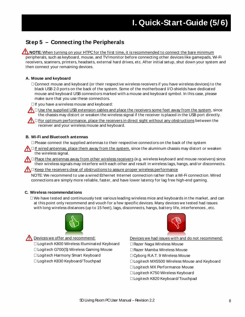
Devices we offer and recommend:
§ Logitech K800 Wireless Illuminated Keyboard
§ Logitech G700(S) Wireless Gaming Mouse
§ Logitech Harmony Smart Keyboard
§ Logitech K830 Keyboard/Touchpad
Devices we had issues with and do not recommend:
§ Razer Naga Wireless Mouse
§ Razer Mamba Wireless Mouse
§ Cyborg R.A.T. 9 Wireless Mouse
§ Logitech MX5500 Wireless Mouse and Keyboard
§ Logitech MX Performance Mouse
§ Logitech K750 Wireless Keyboard
§ Logitech K820 Keyboard/Touchpad
C. Wireless recommendations
§ We have tested and continuously test various leading wireless mice and keyboards in the market, and can at this point only recommend and vouch for a few specific devices. Many devices we tested had issues with long wireless distances (up to 15 feet), lags, disconnects, hangs, battery life, interferences , etc.
SD Living Room PC User Manual – Revision 2.2
I. Quick-Start-Guide (6/6)
9
A. Firing up your STEIGER DYNAMICS HTPC
1. Switch the Power Supply switch at the rear of the system to “I” (on).
2. Press the round Power Button in the front of the system.
3. Your first boot may take a bit longer as usual and the system may turn on and off several times before it boots into Windows. This is normal. Should you run into any problems or error messages, please refer to the first page of the quick start guide, the next section of this manual, “Best Practices”, and/or contact us for help.
B. Windows key
§ We usually pre-activate your Windows license during installation, so you do not have to activate your Windows license when you boot up the system for the first time.
§ If Windows ever asks you for your Windows key, you can find it on the sticker at the rear of the system.
C. Microsoft user account
§ When we install and configure your HTPC we do so with a local account, without any password.
§ We recommend that you change your account type from a local account to a Microsoft account. This will allow you to experience the full integration of Windows cloud services incl. Microsoft OneDrive, Outlook, Store Apps. To do so, please follow the steps below:
1. Navigate to “Control Panel” >>> “User Accounts” .
2. Click on “Make changes to my account in PC settings”.
3. Click on “Switch to a Microsoft account” and follow the instructions.
D. Your binder
Your binder (which you have open right now) is a great place to keep important system software and documentation – we have started you off by including:
§ Manual: Follow the “Quick-Start-Guide”, find out about “Best Practices”, and check out your individual “Manufacturing Log” (LEET).
§ Original Windows Disc: For a any scenarios that require to boot from the Windows DVD, like Automatic Repair or restoring a restore point from boot.
§ Other software: Software that may have been provided by the manufacturers of your system’s components.
Step 6 – Ready to Roll
SD Living Room PC User Manual – Revision 2.2
II. DIY Builder Guide (1/3)
10
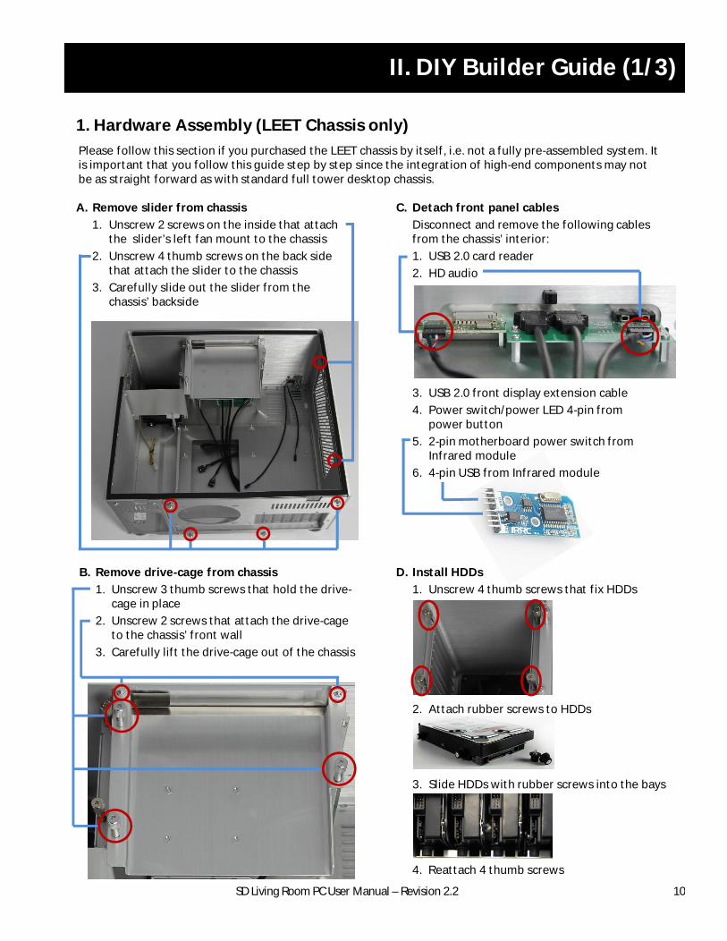
A. Remove slider from chassis
1. Unscrew 2 screws on the inside that attach the slider’s left fan mount to the chassis
2. Unscrew 4 thumb screws on the back side that attach the slider to the chassis
3. Carefully slide out the slider from the chassis’ backside
1. Hardware Assembly (LEET Chassis only)
C. Detach front panel cables
Disconnect and remove the following cables from the chassis’ interior:
1. USB 2.0 card reader
2. HD audio
3. USB 2.0 front display extension cable
4. Power switch/power LED 4-pin from power button
5. 2-pin motherboard power switch from Infrared module
6. 4-pin USB from Infrared module
Please follow this section if you purchased the LEET chassis by itself, i.e. not a fully pre-assembled system. It is important that you follow this guide step by step since the integration of high-end components may not be as straight forward as with standard full tower desktop chassis.
B. Remove drive-cage from chassis
1. Unscrew 3 thumb screws that hold the drive-cage in place
2. Unscrew 2 screws that attach the drive-cage to the chassis’ front wall
3. Carefully lift the drive-cage out of the chassis
D. Install HDDs
1. Unscrew 4 thumb screws that fix HDDs
2. Attach rubber screws to HDDs
3. Slide HDDs with rubber screws into the bays
4. Reattach 4 thumb screws
SD Living Room PC User Manual – Revision 2.2
II. DIY Builder Guide (2/3)
11
1. Hardware Assembly (continued, LEET Chassis only)
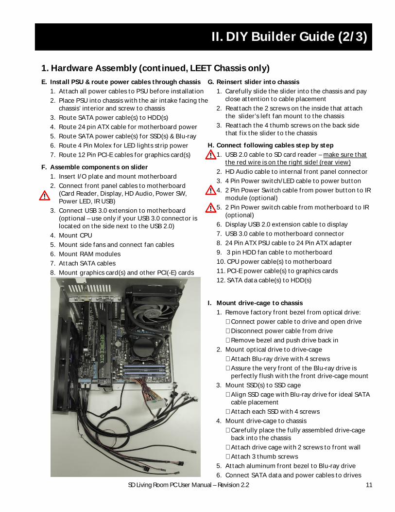
F. Assemble components on slider
1. Insert I/O plate and mount motherboard
2. Connect front panel cables to motherboard (Card Reader, Display, HD Audio, Power SW, Power LED, IR USB)
3. Connect USB 3.0 extension to motherboard (optional – use only if your USB 3.0 connector is located on the side next to the USB 2.0)
4. Mount CPU
5. Mount side fans and connect fan cables
6. Mount RAM modules
7. Attach SATA cables
8. Mount graphics card(s) and other PCI(-E) cards
9. Mount CPU cooler
E. Install PSU & route power cables through chassis
1. Attach all power cables to PSU before installation
2. Place PSU into chassis with the air intake facing the chassis’ interior and screw to chassis
3. Route SATA power cable(s) to HDD(s)
4. Route 24 pin ATX cable for motherboard power
5. Route SATA power cable(s) for SSD(s) & Blu-ray
6. Route 4 Pin Molex for LED lights strip power
7. Route 12 Pin PCI-E cables for graphics card(s)
G. Reinsert slider into chassis
1. Carefully slide the slider into the chassis and pay close attention to cable placement
2. Reattach the 2 screws on the inside that attach the slider’s left fan mount to the chassis
3. Reattach the 4 thumb screws on the back side that fix the slider to the chassis
H. Connect following cables step by step
1. USB 2.0 cable to SD card reader – make sure that the red wire is on the right side! (rear view)
2. HD Audio cable to internal front panel connector
3. 4 Pin Power switch/LED cable to power button
4. 2 Pin Power Switch cable from power button to IR module (optional)
5. 2 Pin Power switch cable from motherboard to IR (optional)
6. Display USB 2.0 extension cable to display
7. USB 3.0 cable to motherboard connector
8. 24 Pin ATX PSU cable to 24 Pin ATX adapter
9. 3 pin HDD fan cable to motherboard
10. CPU power cable(s) to motherboard
11. PCI-E power cable(s) to graphics cards
12. SATA data cable(s) to HDD(s)
I. Mount drive-cage to chassis
1. Remove factory front bezel from optical drive:
§ Connect power cable to drive and open drive
§ Disconnect power cable from drive
§ Remove bezel and push drive back in
2. Mount optical drive to drive-cage
§ Attach Blu-ray drive with 4 screws
§ Assure the very front of the Blu-ray drive is perfectly flush with the front drive-cage mount
3. Mount SSD(s) to SSD cage
§ Align SSD cage with Blu-ray drive for ideal SATA cable placement
§ Attach each SSD with 4 screws
4. Mount drive-cage to chassis
§ Carefully place the fully assembled drive-cage back into the chassis
§ Attach drive cage with 2 screws to front wall
§ Attach 3 thumb screws
5. Attach aluminum front bezel to Blu-ray drive
6. Connect SATA data and power cables to drives
SD Living Room PC User Manual – Revision 2.2
II. DIY Builder Guide (3/3)
2. Software Setup (LEET)
NOTE: Please download the latest LEET Monitor front display software version here: www.steigerdynamics.com/support-downloads.aspx
A. LEET Monitor (recommended)
To utilize the LEET’s built-in 7” front screen best, we recommend to install our LEET Monitor app. It constantly monitors and displays system status info on the LEET’s front screen. Please install the app as follows:
1. When you first boot up your system after Windows is installed, you should automatically see the DisplayLink driver Installer prompt pop up. DisplayLink is the USB graphics chipset connecting the front display to your system.
2. Follow the on-screen instructions and finish the driver installation
3. You should now see the extended Windows desktop on your front display
4. Download the latest LEET Monitor front display software version here: www.steigerdynamics.com/support-downloads.aspx
5. Double-click the downloaded file and follow the on-screen instructions
6. When the installation is finished, the front screen software should be seen in the front display.
NOTE: For more information on how to use and configure your LEET Monitor app please refer to
“III. Best Practices – 2. Software & Apps – A. LEET Monitor” in this document
NOTE: Windows Update will automatically update the DisplayLink driver software periodically. When this happens, LEET Monitor will be deactivated and the Windows desktop will come back to the front screen. To fix this, simply uninstall LEET Monitor (you will keep all your settings) from Control Panel/Programs and Features, and reinstall the latest version from our website.
C. SD Theme Pack (optional)
To install the STEIGER DYNAMICS Dark Windows Theme Pack, please follow these steps:
1. Download the theme pack here: www.steigerdynamics.com/support-downloads.aspx
2. Double-click the downloaded file
12
SD Living Room PC User Manual – Revision 2.2
III. Best Practices (1/4)
13
A. Boot up errors and BIOS settings
§ If you receive the boot up message “Overclocking failed!” (after the system didn’t shutdown properly)1. Press F1 to enter BIOS interface2. Then press F10 to “save and exit”3. The overclock settings should be restored, and your system should boot regularly now
§ Please do not update your BIOS unless explicitly directed by us. Depending on your configuration, your BIOS is a custom version provided by ASUS exclusively to STEIGER DYNAMICS which allows for a refined fan control to minimize noise. Moreover, there are many BIOS settings that we fine tune for optimal system performance and stability. We do not want you to lose those, especially if you have a custom overclocked and/or RAID system. Please note that a BIOS update will not improve performance.
§ If you nevertheless see the need to update your BIOS or if you experience any problem, please do not hesitate to contact us before you proceed.
§ If you lost your initial BIOS settings, in most cases you can restore them as follows:1. Turn on your system and immediately keep the “Delete” key pressed until the BIOS interface loads2. Enter “Advanced Mode” and navigate to “Tool” >>> “ASUS O.C. Profile” >>> “Load from Profile”3. Type “1”, press “Enter”, and confirm with “Yes”4. Press F10 to “save and exit”5. The overclock settings should be restored, and your system should boot regularly now
B. Driver updates
§ All important system drivers will be updated automatically through Windows Update. Please do not attempt to update chipset and SATA controller drivers on your own unless explicitly directed by us. We have installed and thoroughly tested all drivers to ensure optimal performance and stability.
§ Graphics card drivers can be updated when prompted by GeForce experience.
C. Windows Defender & Firewall
§ Your system comes preinstalled with Windows including Windows Defender and Windows Firewall.
§ We highly recommend to keep both solutions always active and up-to-date.
§ We activate Windows Updates with the option “Install updates automatically”.
§ We recommend using a good Third-Party Anti-Virus solution
D. Scaling – Increase text and items on your screen
§ Depending on the distance, size, and resolution of your TV you may want to change the size of items.
§ To change the size of items on your screen please follow the steps below:
1.Navigate to “Control Panel” >>> “Display” >>> Change size of items >>> Let me chose scaling levels
2.Set your preferred option – for Full HDTVs we recommend 125-150%. For 4K TVs we recommend 200-250%. This is dependent on the size of your TV and distance to it. Please try and see what works best.
NOTE: Some apps and games are not optimized for larger scaling and hence may appear blurry or not work fully. This is normal and a minor downside of scaling; however, the number of apps that do not support scaling properly is decreasing. If you experience issues, please deactivate scaling (set to 100%).
E. Sleep Mode & Power Options
The “Sleep Mode” is a great feature that allows you to save money and power but still have your system ready to spring to life almost instantly. We pre-configure every system with the following settings:
§ Turn off the display: “Never” – we recommend “Never”, otherwise sound output via HDMI will also stop as soon as display turns off. Instead, we recommend to change the display off setting in your TV settings.
§ Put the computer to sleep: “Never”– to change this, navigate to “Control Panel” >>> “Power Options”.
RECOMMENDATION: Put your system to sleep rather than shutting it completely down.
1. BIOS, Drivers, and Windows Software & Settings
SD Living Room PC User Manual – Revision 2.2
III. Best Practices (2/4)
14
A. LEET Monitor App (LEET only)
§ The LEET™ comes with a system monitoring app - the “LEET Monitor” - which constantly monitors and displays system status information on the LEET’s front screen.
§ Start app: The LEET Monitor app starts automatically with Windows. If for whatever reason, the app should not start, or if you closed the app and want to re-launch it, you can start the app from the desktop shortcut.
§ Screens: The LEET Monitor features different screens featuring various information and functionality.
1. “Clock”: Analog or digital mode as well as colors can be changed in settings.
2. “Logo”: Display the SD logo. To change the logo, navigate to C:\Program Files (x86)\LEETMonitor\img , backup the original logo.png file, and replace it with your custom 800x480pixel .png file.
3. “System”: See how long your system is up and running and other details like your IP address.
4. “Components 1”: Display details of your LEET’s hardware components.
5. “Components 2”: Display details of your LEET’s hardware components.
6. “Performance”: Monitor system load and temperatures.
7. “Drives”: Display all system partitions/drives and their respective full and remaining capacities.
§ Settings: Right click on the SD icon in the bottom right of your taskbar to open the settings menu.
– Date/Time Modes: Set your preferred date/time mode
– Temperature Unit: Set to Celsius or Fahrenheit
– Auto Mode Screens: Select which screens you like to enable for Auto Mode rotation
– Auto Mode Speed: Set how long each screen should stay in seconds when in Auto Mode rotation
– Change Page Hotkey…: Set your preferred hotkey to skip to next screen
– Auto Mode: If selected, the LEET Monitor rotates through the screens that you activated in “Auto Mode Screen”
– Static Modes: If you selected “Logo”, “System”, “Components 1”, “Components 2”, “Performance”, or “Drives”, the LEET Monitor simply displays one static screen without rotation.
B. Logitech Harmony
To control your STEIGER DYNAMICS HTPC with a Logitech Harmony (or other) universal remote control please add the following profile in your remote control software:Manufacturer: Microsoft >> Model: Windows Media Center
2. Software & Apps
SD Living Room PC User Manual – Revision 2.2
III. Best Practices (3/4)
3. Backup & Restore
A. Backup your files
§ Store your movies/videos, music, office documents and other personal files on the “Storage” partition (D:)
§ Depending on your specific HTPC configuration, the “Storage” partition can either be one single HDD, or two (mirror), three (parity), or four (mirror or parity) HDDs configured as a Windows storage space.
§ While mirror and parity configurations are protecting your “Storage” partition against a single HDD failure, we still recommend to backup your “Storage” partition to external hard drives from time to time.
§ We also recommend using cloud sync services like Microsoft OneDrive or Dropbox for important data.
B. Create a restore point
§ “System” partition (C:) contains your Windows and program/game installation files.
§ Depending on your specific HTPC configuration, the “System” partition can be either one single SSD, or two SSDs in RAID0 (speed mode), RAID1 (mirror mode), or no-RAID.
§ You should in any case, create system restore points from time to time, to be able to fall back to a system status that is functional, in case of any operating system or software/app problems.
§ You can create a system restore point for your “System” partition (C:) as follows:
1. Navigate to “Control Panel” >>> “System” >>> click “ System Protection”. A window should pop now.
2. Click on “Create…” >>> Type in a name for your restore point >>> click “Create”
It should only take a few seconds to create your restore point.
C. Restore your system from a restore point within Windows
§ You can restore your “System” partition (C:) to a previous (functional) system state as follows:
1. Navigate to “Control Panel” >>> “System” >>> “System Protection”. A window will pop up now.
2. Click on “System Restore…” and then “Next >”. This should display several restore points.
3. Check the box “Show more restore points” to display even older restore points incl. the ones we created in the manufacturing process of your HTPC.
4. To restore the original system state, please select “SD Final” and click “Next >”.
5. Click “Finish” to confirm system restore. The restore can take up to 30 minutes. After the restore your system should boot up into the restored functional system stage.
D. Restore, repair, or reload image from boot
§ Should your system not boot into Windows anymore or should you not be able to restore a functioning system state as explained above, try to do the following:
1. Place original Window DVD into your Blu-ray drive.
2. Turn off your system.
3. Turn on your system and immediately keep the “F8” key pressed until the BIOS boot menu loads.
4. Select your Blu-ray drive and press “Enter”.
5. Your system will now boot from the Windows 8 DVD.
6. Click “Next” >>> “Repair your Computer” >>> “Troubleshoot” >>> “Advanced Options”
7. A) If you like to restore a previous system state, click “System Restore” and follow the instructions.
B) If A) does not solve your problem, click “Automatic Repair” and follow the instructions.
C) If neither A) nor B) resolve your problem, click on “System Image Recovery“. It will ask you to “insert the final backup DVD”. Insert the “SD System Image” Blu-ray from your folder and click “Retry”. This will completely erase and clean install your System partition (C:). NOTE: All data on C: will be lost.
15
SD Living Room PC User Manual – Revision 2.2
III. Best Practices (4/4)
B. Custom liquid cooling maintenance
§ Standard, pre-sealed CPU liquid cooling solutions are maintenance free!
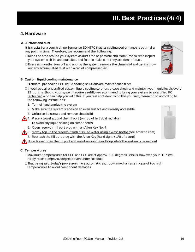
§ If you have a handcrafted custom liquid cooling solution, please check and maintain your liquid levels every 12 months. Should your system require a refill, we recommend to bring your system to a certified PC technician who can help you with this. If you feel confident to do this yourself, please do so according to the following instructions:
1. Turn off and unplug the system
2. Make sure the system stands on an even surface and is easily accessible
3. Unfasten lid screws and remove chassis lid
4. Place a towel around the fill port (on top of left dual radiator)
to avoid any liquid spilling on components
5. Open reservoir fill port plug with an Allen Key No. 4
6. Slowly top up the reservoir with distilled water using a wash bottle (see Amazon.com)
7. Reattach the fill port plug with the Allen Key (hand tight + 1/8 of a turn)
Note: Never open the fill port and maintain your liquid loop while the system is turned on!
C. Temperatures
§ Maximum temperatures for CPU and GPU are at approx. 100 degrees Celsius; however, your HTPC will rarely reach temps >80 degrees even under full load.
§ That being said, today’s processors have automatic shut down mechanisms in case of too high temperatures to avoid component damages.
4. Hardware
A. Airflow and dust
It is crucial for a your high-performance SD HTPC that its cooling performance is optimal at any point in time. Therefore, we recommend the following:
§ Keep the area around your system as dust free as possible and from time to time inspect your system’s air in- and outtakes, and fans to make sure they are clear of dust.
§ Every six months, turn off and unplug the system, remove the chassis lid and gently blow out any accumulated dust with a can of compressed air.
16

SD Living Room PC User Manual – Revision 2.2 19
STEIGER DYNAMICS LLC
1181 ODDSTAD DR
REDWOOD CITY, CA 94063, USA
STEIGERDYNAMICS.COM
TOLL-FREE: 1-855-915-9000