Embed Size (px)
Citation preview

SDSFoil no 1
How to make real systems:Implementation design, deployment and realisation

SDSFoil no 2
Implementation design, deployment and realisation
Realisation sof tware electronics mechanics
Deployment
Functionality (Structure Behaviour)
Descriptions
Performance … Dependability ….
Objects Properties
Tests… Measurements
Services …
Non-functional properties

SDSFoil no 3
Realisation
sof tware electronics mechanics
Deployment
Functionality
Descriptions Structure Behaviour
Realisation
Is a precise technical definition of the realisation in terms of the technologies used, such as mechanics, electronics and software
Is necessary to actually produce a working system
The choice of realisation depends on what properties are desired from the realisation itself (often called non-functional properties)
–So, what’s the problem?
–How is implementation design different from functional design?
SDSFoil no 4
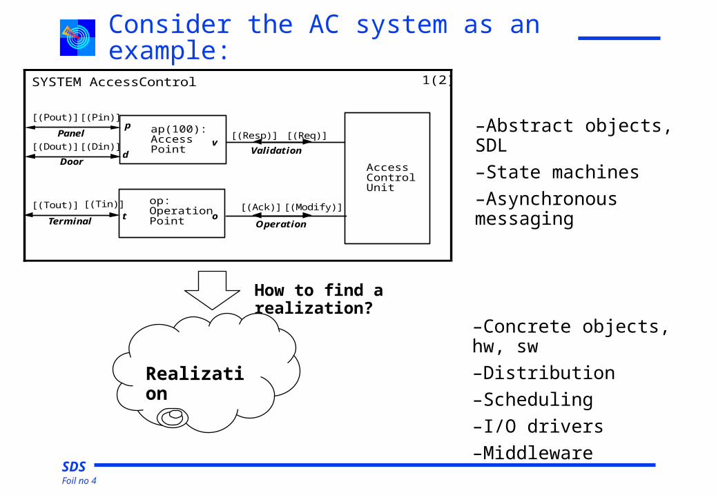
Consider the AC system as an example:
SYSTEM AccessControl 1(2)
Access
Validation
[(Pin)][(Pout)]
[(Resp)] [(Req)]ap(100):p
vAccessPanel
Doord
Operation
[(Tin)][(Tout)] [(Ack)] [(Modify)]op:
t oOperationTerminal Point
Point [(Dout)]
UnitControl
[(Din)]
–Abstract objects, SDL
–State machines
–Asynchronous messaging
–Concrete objects, hw, sw
–Distribution
–Scheduling
–I/O drivers
–Middleware
Realization
How to find a realization?

SDSFoil no 5
SYSTEM AccessControl 1(2)
Access
Validation
[(Pin)][(Pout)]
[(Resp)] [(Req)]ap(100):p
vAccessPanel
Doord
Operation
[(Tin)][(Tout)] [(Ack)] [(Modify)]op:
t oOperationTerminal Point
Point [(Dout)]
UnitControl
[(Din)]
A typical realization
HWHW
OSOS
MiddlewareMiddleware
legacylegacy app appapp app i/oi/o

SDSFoil no 6
SYSTEM AccessControl 1(2)
Access
Validation
[(Pin)][(Pout)]
[(Resp)] [(Req)]ap(100):p
vAccessPanel
Doord
Operation
[(Tin)][(Tout)] [(Ack)] [(Modify)]op:
t oOperationTerminal Point
Point [(Dout)]
UnitControl
[(Din)]
Deployment mapping
HWHW
OSOS
MiddlewareMiddleware
legacylegacy app appapp app i/oi/o
Key design issues:
1. Performance
2. Timeliness
3. Availability

SDSFoil no 7
SYSTEM AccessControl 1(2)
Access
Validation
[(Pin)][(Pout)]
[(Resp)] [(Req)]ap(100):p
vAccessPanel
Doord
Operation
[(Tin)][(Tout)] [(Ack)] [(Modify)]op:
t oOperationTerminal Point
Point [(Dout)]
UnitControl
[(Din)]
Communication options
HWHW
OSOS
MiddlewareMiddleware
legacylegacy app appapp app i/oi/o
1. Synchronous – invocation: method calls, RMI, CORBA, Web, SOAP, …
2. Asynchronous – messaging: TCP, UDP, MoM, Actor Router, MQTT, …
3. Physical lines and I/O

SDSFoil no 8
Synchronous communication using method calls
P1[a,b] [c,d] [e,f]
P2 P3
P1
c(), d()
P2
SDL
UML classes
state
e(), f()
P3
statestate
a(), b()
Implement ImplementImplement
any limitations?
Pseudo code of class P2:integer state;void c(){switch (state){ case 1: P3.e(); P3.f();
State:=2; return; case 2: ....; return;}}}
void d(){switch (state){ case 1: P3.f(); State:=3; return; case 2: ....; return;}}}

SDSFoil no 9
Conditions for synchronous communication by procedure/method calls :
Structure: The (sub) system must behave like a single procedure/method call tree, a single sequential activity thread.
Waiting: Waiting for external events or timers only at the root of the tree, unless the waiting time is negligible. No mixed initiatives!!
Return signals: For each signal sent down the tree, not more than one reply signal is returned to the sender (implemented as a procedure return value).
Return signals must be sent as the last action on a transition before entering the next state, i.e. only one pr transition.
Timing: There is sufficient time between each external input signal to process all signals and outputs that follows from it, and to return to the input process. Consequently, there is no need to give pre-emptive priority to the input process.
Distribution: The added RPC/RMI overhead must be acceptable
What if there are many instances?

SDSFoil no 10
Asynchronous communication using messages
Structure: no restrictions
Distribution: transparent, efficient and scalable
Memory management: required – here freepools
Structure: no restrictions
Distribution: transparent, efficient and scalable
Memory management: required – here freepools
ReceiverSendS:gs
message
F:gs
buffer
Send
wait
wait
sender
buffer
message

SDSFoil no 11
What about performance?
• Synchronous calls are only efficient within a single activity thread!
• Asynchronous messaging is normally more efficient between scheduled processes and across networks even with the overhead of queues!
• Synchronous calls are only efficient within a single activity thread!
• Asynchronous messaging is normally more efficient between scheduled processes and across networks even with the overhead of queues!
Because with messaging:
– scheduling is simple
– processes are not blocked when communicating
– context switching is reduced.

SDSFoil no 12
Communication
• SDL and UML does not restrict your implementation options!
• You are free to use your preferred communication solution
• As long as it fits your application problem!!
• SDL and UML does not restrict your implementation options!
• You are free to use your preferred communication solution
• As long as it fits your application problem!!

SDSFoil no 13
Is synchronous communication OK in
• The ATM system?
• The access control system?
• The Taxi system?
• Call handling, the LocalSwitch?
• Web services, e.g. internet banking?
• A City guide?
• The ATM system?
• The access control system?
• The Taxi system?
• Call handling, the LocalSwitch?
• Web services, e.g. internet banking?
• A City guide?

SDSFoil no 14
State machines: state oriented programState-1:
Input:= Wait(Inport,Indefinetely);
CASE Input OF (Signal-a): Action-1; GOTO State-3;
(Signal-b): Action-2; GOTO State-5;
ELSE: Action-3; GOTO State-1;
ESAC;State-2:
Input:= Wait(Inport,Indefinetely);
CASE Input OF (Signal-c): ...
...
State-1:
Input:= Wait(Inport,Indefinetely);
CASE Input OF (Signal-a): Action-1; GOTO State-3;
(Signal-b): Action-2; GOTO State-5;
ELSE: Action-3; GOTO State-1;
ESAC;State-2:
Input:= Wait(Inport,Indefinetely);
CASE Input OF (Signal-c): ...
...
State-1
State-1State-5State-3
signal-a signal-b *
Action-1Action-1 Action-1Action-2 Action-1Action-3
What if there are many instances?

SDSFoil no 15
State machines: Action oriented program
NEWMODE CONTROL_STATES =SET(State-1, State-2, State-3, ...);
DCL State CONTROL_STATES;
DO FOR EVER Input:= Wait(Inport,Indefinetely); CASE State OF State-1: CASE Input OF (Signal-a):Action-1; State:= State-3; (Signal-b):Action-2; State:= State-5; ELSE: Action-3; State:= State-1; ESAC; State-2: CASE Input OF (Signal-c): ... .... ESAC;OD;
State-1
State-1State-5State-3
signal-a signal-b *
Action-1Action-1 Action-1Action-2 Action-1Action-3
What if there are many instances now?

SDSFoil no 16
Implementation from Exercise 2
RTS:
Do forever
Begin
msg := inq.receiveMessage(); //input
fsm:= findObject(msg.destination) //select process instance
fsm.run(msg);
End;
inqinq RTSRTS
P1
Run
state
P1
Run
state
P1
run
state
P1
run
state
Pn
Run
state
Pn
Run
state
Pn
run
state
Pn
run
state

SDSFoil no 17
State machines: table driven code
Process InstanceState
(*): Data
ST- Table
Process Type
Output
Input
SS TYPE FSM
(+): Action
FSM-Support
Signal
Signalname
(*): Param.
do foreverbegin wait (Inport);
Use Signalname and State as key to Transition Record in ST-table;Call Action;State := Next:State;
end;
inport

SDSFoil no 18
State machines
• SDL/UML does not restrict your implementation options
• You are free to use any language and platform you like
• Using a runtime support system helps to simplify coding and testing.
• RTS features:
•Signal addressing
•Signal sending and receiving
•Timers
•Process scheduling
•SDL Procedure calls and composite states
•State-machine coding

SDSFoil no 19
Runtime support – virtual SDL machines

SDSFoil no 20
Message Routing
Error Handling
Operat. System
Application: FSM
<1>
<1> = IMPLEMENT [ AccessControl.LocalUnit]
Display Out
SW TYPE LocalUnitSoftware
Channel input
Channel output
Key Input
Card- Reader
Card i/o
Door Lock unit
Door Lock i/o
Display
Key- board
(1,10): Panel Hw
Panel Bus
Out Channel
In Channel
A software design

SDSFoil no 21
OS
Software categories
Message Routing
Error Handling
Operat. System
Application: FSM
<1>
<1> = IMPLEMENT [ AccessControl.LocalUnit]
Display Out
SW TYPE LocalUnitSoftware
Channel input
Channel output
Key Input
Card- Reader
Card i/o
Door Lock unit
Door Lock i/o
Display
Key- board
(1,10): Panel Hw
Panel Bus
Out Channel
In Channel
middleware
errhSDL
supportI/O
application

SDSFoil no 22
Logical and physical communication
Message Routing
Error Handling
Operat. System
Application: FSM
<1>
<1> = IMPLEMENT [ AccessControl.LocalUnit]
Display Out
SW TYPE LocalUnitSoftware
Channel input
Channel output
Key Input
Card- Reader
Card i/o
Door Lock unit
Door Lock i/o
Display
Key- board
(1,10): Panel Hw
Panel Bus
Out Channel
In Channel
BLOCK LocalStation BLOCK Central unit
User
Abstract system (SDL)
Concrete system
logical
physical
physical
logical

SDSFoil no 23
Routing module
Address: PId
Signal
Address:PId
Semaphore
Semaphore
Semaphore
Address map
Routing procedure
S1:gs
S2: gs
Sn:gs
Message routing
Signalname
(*): Param.
Address:PId
Address:PId

SDSFoil no 24
How are concrete systems different from
abstract SDL and UML systems? There are fundamental differences:
1. processing takes time;
2. errors and noise do occur;
3. physical distances must be covered;
4. resources are finite;
5. data types are concrete and not abstract.
and conceptual differences:
6. in communication primitives;
7. in concurrency;
8. in synchronisation primitives;
9. in language primitives.
There are fundamental differences:
1. processing takes time;
2. errors and noise do occur;
3. physical distances must be covered;
4. resources are finite;
5. data types are concrete and not abstract.
and conceptual differences:
6. in communication primitives;
7. in concurrency;
8. in synchronisation primitives;
9. in language primitives.

SDSFoil no 25
Realisation
sof tware electronics mechanics
Deployment
Functionality
Descriptions Structure Behaviour
Deployment/Implementation design
Describes aspects that come in addition to the functionality, such as distribution, hardware/software allocation and use of middleware and defines a mapping between functionality and realisation by:
• describing the realisation (the physical system) on a high level
• identifying the technologies used
• describing how and where the functionality is realised
• describes configurations
Serves together with functionality as the main documentation.
configuration data:
–priorities;
–versions;
–etc.