Embed Size (px)
Citation preview

SpecificationsWingspan: 30 in (760mm)Length: 23 in (595mm)Wing Area: 310 sq in (20.0 sq dm)Weight w/battery: 7.5–8.5 oz (210–225 g)Weight w/o battery: 7 oz (200 g)Radio: 3-channels with 2 sub-micro servos
S.E.5a Slow Flyer ARFAssembly Manual
2 E-flite S.E.5a Slow Flyer ARF Assembly Manual
IntroductionThe S.E.5a was a fast, maneuverable WWI fighter plane. Together with the Sopwith Camel, the S.E.5a was instrumental in regaining allied air superiority in the summer of 1917 and maintaining it for the rest of the war. Twenty-two squadrons of the RFC and the US Air Corps were flying the S.E.5a by the time of the Armistice. E-flite’s S.E.5a Slow Flyer 250 is an electric, semi-scale version of the famous WWI fighter. A vacuum-molded foam fuselage keeps weight to a minimum while also contributing to the great scale looks of this aircraft. Its biplane design affords low weight as well as substantially reduced wing loading for a more majestic type slow flight, and the ARF design means a shorter build time. Specifically designed for use with an E-flite® Park 250 Brushless Outrunner Motor, the S.E.5a is a fantastic flying foamie with outstanding slow speed characteristics—making it perfect for indoor flight.
Using the ManualThis manual is divided into sections to help make assembly easier to understand, and to provide breaks between each major section. In addition, check boxes have been placed next to each step to keep track of each step completed. Steps with a single circle () are performed once, while steps with two circles ( ) indicate that the step will require repeating, such as for a right or left wing panel, two servos, etc.
Remember to take your time and follow the directions.
Table of ContentsSpecifications .........................................................................1Introduction ............................................................................2Using the Manual ...................................................................2Contents of Kit/Parts Layout ....................................................3Required Radio Equipment ......................................................3Motor Setup ...........................................................................4Optional Accessories ..............................................................4Note on Lithium Polymer Batteries ...........................................4Required Tools and Adhesives .................................................4Warning ................................................................................4Warranty Period ....................................................................4Limited Warranty ...................................................................5Damage Limits .......................................................................5Safety Precautions ..................................................................5Questions, Assistance, and Repairs .........................................6Inspection or Repairs ..............................................................6Warranty Inspection and Repairs ............................................6Non-Warranty Repairs ...........................................................6Safety, Precautions, and Warnings ..........................................7Motor Installation ...................................................................7Rudder and Elevator Installation ............................................10Radio Installation ..................................................................12Wing Installation ..................................................................15Landing Gear Installation ......................................................18Wing Rigging Installation ......................................................19Control Throws .....................................................................21Center of Gravity .................................................................22Range Test Your Radio ..........................................................22Preflight ...............................................................................23Flying the S.E.5a Slow Flyer ..................................................232007 Official AMA National Model Aircraft Safety Code ......24
3E-flite S.E.5a Slow Flyer ARF Assembly Manual
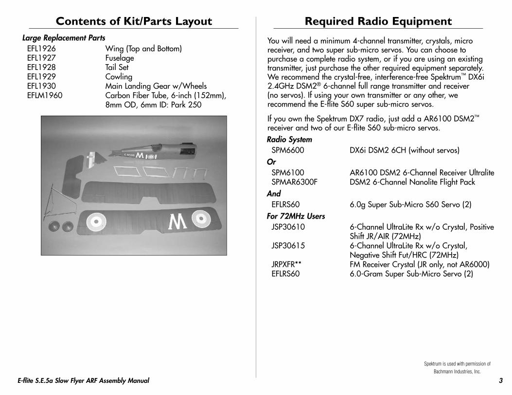
Contents of Kit/Parts LayoutLarge Replacement Parts
EFL1926 Wing (Top and Bottom)EFL1927 FuselageEFL1928 Tail SetEFL1929 CowlingEFL1930 Main Landing Gear w/WheelsEFLM1960 Carbon Fiber Tube, 6-inch (152mm),
8mm OD, 6mm ID: Park 250
Required Radio Equipment
You will need a minimum 4-channel transmitter, crystals, micro receiver, and two super sub-micro servos. You can choose to purchase a complete radio system, or if you are using an existing transmitter, just purchase the other required equipment separately. We recommend the crystal-free, interference-free Spektrum™ DX6i 2.4GHz DSM2® 6-channel full range transmitter and receiver (no servos). If using your own transmitter or any other, we recommend the E-flite S60 super sub-micro servos.
If you own the Spektrum DX7 radio, just add a AR6100 DSM2™ receiver and two of our E-flite S60 sub-micro servos.Radio System
SPM6600 DX6i DSM2 6CH (without servos)Or
SPM6100 AR6100 DSM2 6-Channel Receiver UltraliteSPMAR6300F DSM2 6-Channel Nanolite Flight Pack
AndEFLRS60 6.0g Super Sub-Micro S60 Servo (2)
For 72MHz UsersJSP30610 6-Channel UltraLite Rx w/o Crystal, Positive
Shift JR/AIR (72MHz)JSP30615 6-Channel UltraLite Rx w/o Crystal,
Negative Shift Fut/HRC (72MHz)JRPXFR** FM Receiver Crystal (JR only, not AR6000)EFLRS60 6.0-Gram Super Sub-Micro Servo (2)
Spektrum is used with permission of Bachmann Industries, Inc.
4 E-flite S.E.5a Slow Flyer ARF Assembly Manual
Motor SetupEFLM1130 Park 250 Outrunner, 2200KvEFLA1010 10A Brushless ESCEFLB4302SJ 430mAh 2-Cell 7.4V Li-Po, JSTGWSEP6050B Electric Propeller, 6x5 Slow-FlyerEFLC3005 Celectra 1- to 3-cell Li-Po Charger
Optional AccessoriesEFLA110 Power MeterHAN172 Hangar 9 Digital Servo and
Rx Current Meter
Note on Lithium Polymer BatteriesLithium Polymer batteries are significantly more volatile than alkaline or Ni-Cd/Ni-MH batteries used in RC applications. All manufacturer’s instructions and warnings must be followed closely. Mishandling of Li-Po batteries can result in fire. Always follow the manufacturer’s instructions when disposing of Lithium Polymer batteries.
Required Tools and AdhesivesTools & Equipment
EFLA250 Park Flyer Tool Assortment, 5-pieceOr Purchase Separately
EFLA257 Screwdriver, #0 Phillips (or included with EFLA250)
Hobby knife Felt-tipped penSquare SandpaperPin drill Drill Bit: 1/16 in (1.5mm)Pliers Side CuttersRuler Screwdriver, #1 PhillipsThin CA Needle
AdhesivesEFLA208 Foam CA 1oz/Activator 2oz PackRTV silicone
WarningAn RC aircraft is not a toy! If misused, it can cause serious bodily harm and damage to property. Fly only in open areas, preferably at AMA (Academy of Model Aeronautics) approved flying sites, following all instructions included with your radio.
Keep loose items that can get entangled in the propeller away from the prop, including loose clothing, or other objects such as pencils and screwdrivers. Especially keep your hands away from the propeller.
Warranty PeriodHorizon Hobby, Inc., (Horizon) warranties that the Products purchased (the “Product”) will be free from defects in materials and workmanship at the date of purchase by the Purchaser.
5E-flite S.E.5a Slow Flyer ARF Assembly Manual
Limited Warranty(a) This warranty is limited to the original Purchaser ("Purchaser") and is not transferable. REPAIR OR REPLACEMENT AS PROVIDED UNDER THIS WARRANTY IS THE EXCLUSIVE REMEDY OF THE PURCHASER. This warranty covers only those Products purchased from an authorized Horizon dealer. Third party transactions are not covered by this warranty. Proof of purchase is required for warranty claims. Further, Horizon reserves the right to change or modify this warranty without notice and disclaims all other warranties, express or implied.
(b) Limitations- HORIZON MAKES NO WARRANTY OR REPRESENTATION, EXPRESS OR IMPLIED, ABOUT NON-INFRINGEMENT, MERCHANTABILITY OR FITNESS FOR A PARTICULAR PURPOSE OF THE PRODUCT. THE PURCHASER ACKNOWLEDGES THAT THEY ALONE HAVE DETERMINED THAT THE PRODUCT WILL SUITABLY MEET THE REQUIREMENTS OF THE PURCHASER’S INTENDED USE.
(c) Purchaser Remedy- Horizon's sole obligation hereunder shall be that Horizon will, at its option, (i) repair or (ii) replace, any Product determined by Horizon to be defective. In the event of a defect, these are the Purchaser's exclusive remedies. Horizon reserves the right to inspect any and all equipment involved in a warranty claim. Repair or replacement decisions are at the sole discretion of Horizon. This warranty does not cover cosmetic damage or damage due to acts of God, accident, misuse, abuse, negligence, commercial use, or modification of or to any part of the Product. This warranty does not cover damage due to improper installation, operation, maintenance, or attempted repair by anyone other than Horizon. Return of any goods by Purchaser must be approved in writing by Horizon before shipment.
Damage LimitsHORIZON SHALL NOT BE LIABLE FOR SPECIAL, INDIRECT OR CONSEQUENTIAL DAMAGES, LOSS OF PROFITS OR PRODUCTION OR COMMERCIAL LOSS IN ANY WAY CONNECTED WITH THE PRODUCT, WHETHER SUCH CLAIM IS BASED IN CONTRACT, WARRANTY, NEGLIGENCE, OR STRICT LIABILITY. Further, in no event shall the liability of Horizon exceed the individual price of the Product on which liability is asserted. As Horizon has no control over use, setup, final assembly, modification or misuse, no liability shall be assumed nor accepted for any resulting damage or injury. By the act of use, setup or assembly, the user accepts all resulting liability.
If you as the Purchaser or user are not prepared to accept the liability associated with the use of this Product, you are advised to return this Product immediately in new and unused condition to the place of purchase.
Law: These Terms are governed by Illinois law (without regard to conflict of law principals).
Safety PrecautionsThis is a sophisticated hobby Product and not a toy. It must be operated with caution and common sense and requires some basic mechanical ability. Failure to operate this Product in a safe and responsible manner could result in injury or damage to the Product or other property. This Product is not intended for use by children without direct adult supervision. The Product manual contains instructions for safety, operation and maintenance. It is essential to read and follow all the instructions and warnings in the manual, prior to assembly, setup or use, in order to operate correctly and avoid damage or injury.
6 E-flite S.E.5a Slow Flyer ARF Assembly Manual
Questions, Assistance, and RepairsYour local hobby store and/or place of purchase cannot provide warranty support or repair. Once assembly, setup or use of the Product has been started, you must contact Horizon directly. This will enable Horizon to better answer your questions and service you in the event that you may need any assistance. For questions or assistance, please direct your email to [email protected], or call 877.504.0233 toll free to speak to a service technician.
Inspection or RepairsIf this Product needs to be inspected or repaired, please call for a Return Merchandise Authorization (RMA). Pack the Product securely using a shipping carton. Please note that original boxes may be included, but are not designed to withstand the rigors of shipping without additional protection. Ship via a carrier that provides tracking and insurance for lost or damaged parcels, as Horizon is not responsible for merchandise until it arrives and is accepted at our facility. A Service Repair Request is available at www.horizonhobby.com on the “Support” tab. If you do not have internet access, please include a letter with your complete name, street address, email address and phone number where you can be reached during business days, your RMA number, a list of the included items, method of payment for any non-warranty expenses and a brief summary of the problem. Your original sales receipt must also be included for warranty consideration. Be sure your name, address, and RMA number are clearly written on the outside of the shipping carton.
Warranty Inspection and RepairsTo receive warranty service, you must include your original sales receipt verifying the proof-of-purchase date. Provided warranty conditions have been met, your Product will be repaired or replaced free of charge. Repair or replacement decisions are at the sole discretion of Horizon Hobby.
Non-Warranty RepairsShould your repair not be covered by warranty the repair will be completed and payment will be required without notification or estimate of the expense unless the expense exceeds 50% of the retail purchase cost. By submitting the item for repair you are agreeing to payment of the repair without notification. Repair estimates are available upon request. You must include this request with your repair. Non-warranty repair estimates will be billed a minimum of ½ hour of labor. In addition you will be billed for return freight. Please advise us of your preferred method of payment. Horizon accepts money orders and cashiers checks, as well as Visa, MasterCard, American Express, and Discover cards. If you choose to pay by credit card, please include your credit card number and expiration date. Any repair left unpaid or unclaimed after 90 days will be considered abandoned and will be disposed of accordingly. Please note: non-warranty repair is only available on electronics and model engines.
Electronics and engines requiring inspection or repair should be shipped to the following address:
Horizon Service Center 4105 Fieldstone Road
Champaign, Illinois 61822
All other Products requiring warranty inspection or repair should be shipped to the following address:
Horizon Product Support 4105 Fieldstone Road
Champaign, Illinois 61822
Please call 877-504-0233 with any questions or concerns regarding this product or warranty.
7E-flite S.E.5a Slow Flyer ARF Assembly Manual
Safety, Precautions, and WarningsAs the user of this product, you are solely responsible for operating it in a manner that does not endanger yourself and others or result in damage to the product or the property of others.
Carefully follow the directions and warnings for this and any optional support equipment (chargers, rechargeable battery packs, etc.) that you use.
This model is controlled by a radio signal that is subject to interference from many sources outside your control. This interference can cause momentary loss of control so it is necessary to always keep a safe distance in all directions around your model, as this margin will help to avoid collisions or injury.
• Always operate your model in an open area away from cars, traffic, or people.
• Avoid operating your model in the street where injury or damage can occur.
• Never operate the model out into the street or populated areas for any reason.
• Never operate your model with low transmitter batteries.
• Carefully follow the directions and warnings for this and any optional support equipment (chargers, rechargeable battery packs, etc.) that you use.
• Keep all chemicals, small parts and anything electrical out of the reach of children.
• Moisture causes damage to electronics. Avoid water exposure to all equipment not specifically designed and protected for this purpose.
Motor InstallationRequired Parts
• Fuselage • Receiver• Park 250 Brushless motor • Electronic speed control (ESC)• 11/2-inch (38mm) motor tube • Super sub-micro servos (2)• Propeller
Required Tools and Adhesives• Phillips screwdriver: #0 • RTV silicone• Double-sided tape • Foam-safe CA• Sandpaper • Pin drill• Drill bit: 1/16-inch (1.5mm)
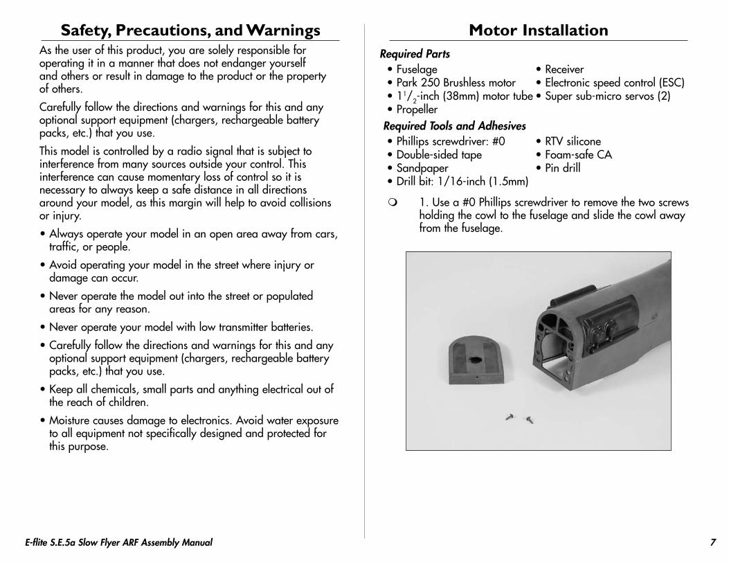
1. Use a #0 Phillips screwdriver to remove the two screws holding the cowl to the fuselage and slide the cowl away from the fuselage.
8 E-flite S.E.5a Slow Flyer ARF Assembly Manual8 E-flite S.E.5a Slow Flyer ARF Assembly Manual
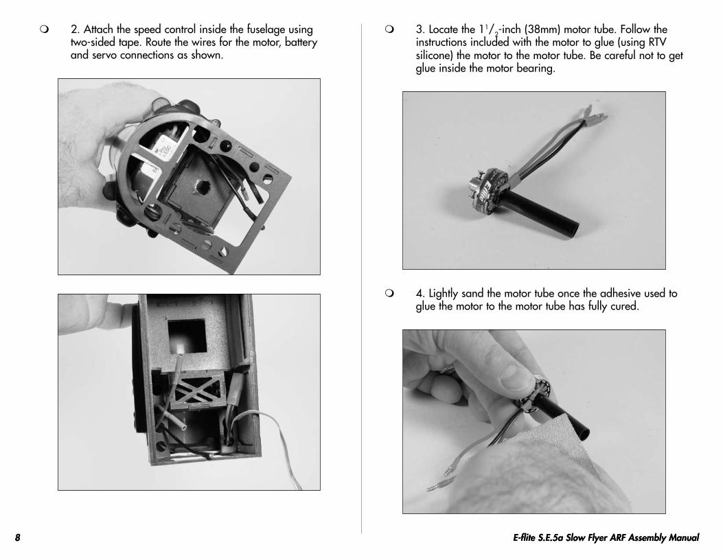
2. Attach the speed control inside the fuselage using two-sided tape. Route the wires for the motor, battery and servo connections as shown.
3. Locate the 11/2-inch (38mm) motor tube. Follow the instructions included with the motor to glue (using RTV silicone) the motor to the motor tube. Be careful not to get glue inside the motor bearing.
4. Lightly sand the motor tube once the adhesive used to glue the motor to the motor tube has fully cured.
9E-flite S.E.5a Slow Flyer ARF Assembly Manual 9E-flite S.E.5a Slow Flyer ARF Assembly Manual
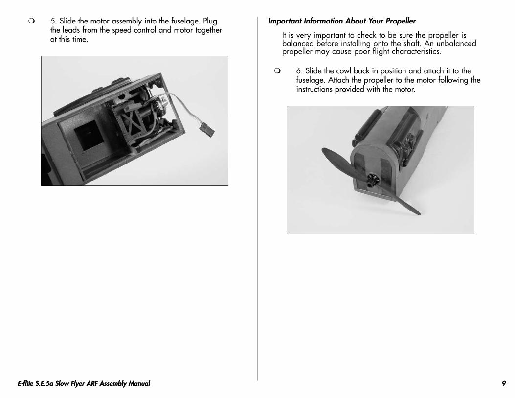
5. Slide the motor assembly into the fuselage. Plug the leads from the speed control and motor together at this time.
Important Information About Your Propeller
It is very important to check to be sure the propeller is balanced before installing onto the shaft. An unbalanced propeller may cause poor flight characteristics.
6. Slide the cowl back in position and attach it to the fuselage. Attach the propeller to the motor following the instructions provided with the motor.
10 E-flite S.E.5a Slow Flyer ARF Assembly Manual
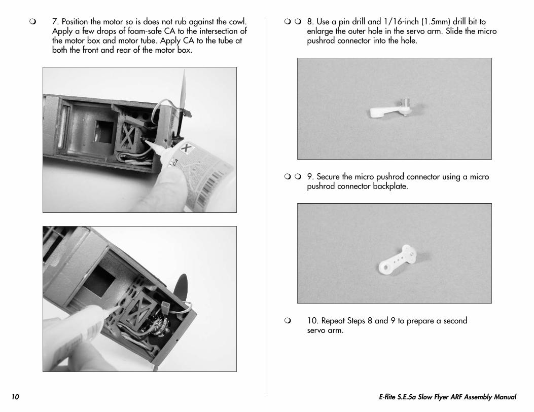
7. Position the motor so is does not rub against the cowl. Apply a few drops of foam-safe CA to the intersection of the motor box and motor tube. Apply CA to the tube at both the front and rear of the motor box.
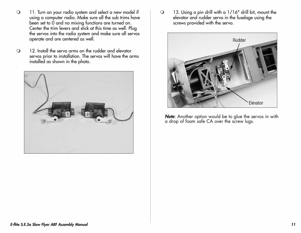
8. Use a pin drill and 1/16-inch (1.5mm) drill bit to enlarge the outer hole in the servo arm. Slide the micro pushrod connector into the hole.
9. Secure the micro pushrod connector using a micro pushrod connector backplate.
10. Repeat Steps 8 and 9 to prepare a second servo arm.
11E-flite S.E.5a Slow Flyer ARF Assembly Manual
11. Turn on your radio system and select a new model if using a computer radio. Make sure all the sub trims have been set to 0 and no mixing functions are turned on. Center the trim levers and stick at this time as well. Plug the servos into the radio system and make sure all servos operate and are centered as well.
12. Install the servo arms on the rudder and elevator servos prior to installation. The servos will have the arms installed as shown in the photo.
13. Using a pin drill with a 1/16" drill bit, mount the elevator and rudder servo in the fuselage using the screws provided with the servo.
Note: Another option would be to glue the servos in with a drop of foam safe CA over the screw lugs.
12 E-flite S.E.5a Slow Flyer ARF Assembly Manual
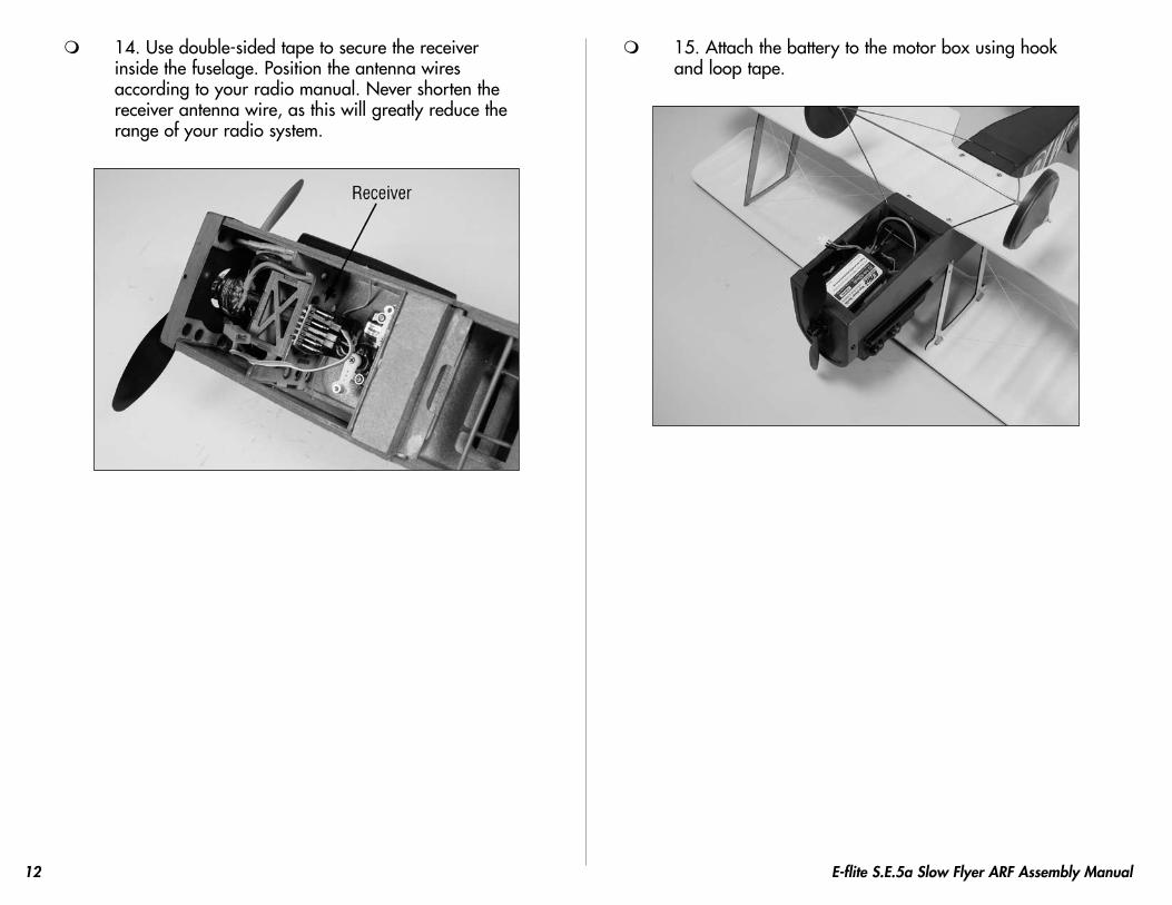
14. Use double-sided tape to secure the receiver inside the fuselage. Position the antenna wires according to your radio manual. Never shorten the receiver antenna wire, as this will greatly reduce the range of your radio system.
15. Attach the battery to the motor box using hook and loop tape.
13E-flite S.E.5a Slow Flyer ARF Assembly Manual
Important Information About Your Brushless ESC
Make sure your ESC brake is programmed to Off. Also, be sure to use an ESC with the proper low-voltage cutoff and it is set correctly for the batteries you are using.
Note: Never check the motor rotation on the bench with the propeller installed. The plane could move and cause serious injury. Always check the motor without the propeller to avoid injury.
16. Turn on the transmitter and bring the throttle trim and stick to the low throttle position. Plug the battery into the speed control and check the operation of the motor. It should rotate counterclockwise when viewed from the front of the aircraft. Use the instructions provided with your ESC to make corrections to the direction of rotation of the motor if necessary.
Note: If the motor rubs on the cowl, enlarge the hole in the cowl for the motor so the motor does not rub the cowl.
Wing InstallationRequired Parts
• Wing (top and bottom) • Outer strut (2)• Cabane strut (2)• #2 x 5/8-inch sheet metal screw (12)
Required Tools and Adhesives• Foam-safe CA • Ruler• Hobby knife • Felt-tipped pen• Pin drill • Drill bit: 1/16-inch (1.5mm)• Phillips screwdriver: #1 • Sandpaper
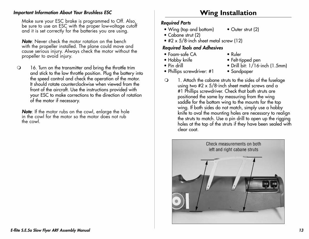
1. Attach the cabane struts to the sides of the fuselage using two #2 x 5/8-inch sheet metal screws and a #1 Phillips screwdriver. Check that both struts are positioned the same by measuring from the wing saddle for the bottom wing to the mounts for the top wing. If both sides do not match, simply use a hobby knife to oval the mounting holes are necessary to realign the struts to match. Use a pin drill to open up the rigging holes at the top of the struts if they have been sealed with clear coat.
14 E-flite S.E.5a Slow Flyer ARF Assembly Manual
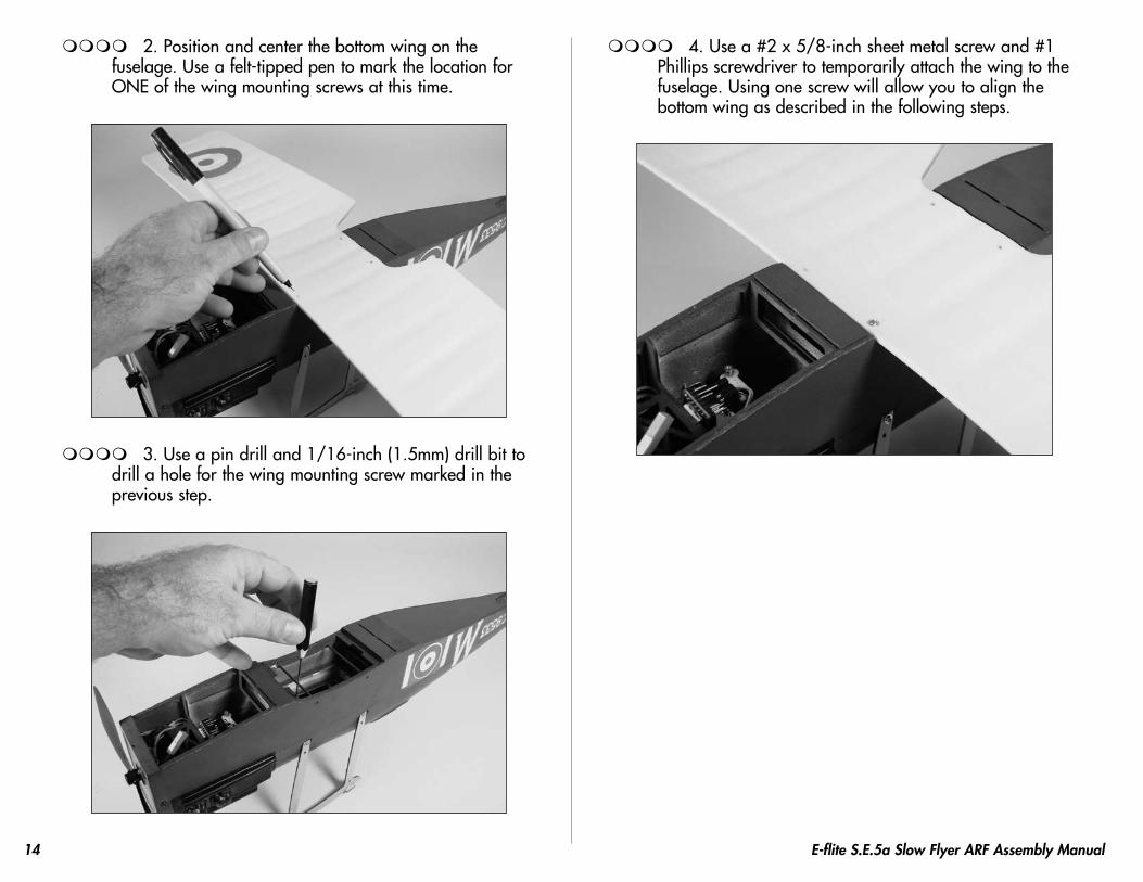
2. Position and center the bottom wing on the fuselage. Use a felt-tipped pen to mark the location for ONE of the wing mounting screws at this time.
3. Use a pin drill and 1/16-inch (1.5mm) drill bit to drill a hole for the wing mounting screw marked in the previous step.
4. Use a #2 x 5/8-inch sheet metal screw and #1 Phillips screwdriver to temporarily attach the wing to the fuselage. Using one screw will allow you to align the bottom wing as described in the following steps.
15E-flite S.E.5a Slow Flyer ARF Assembly Manual
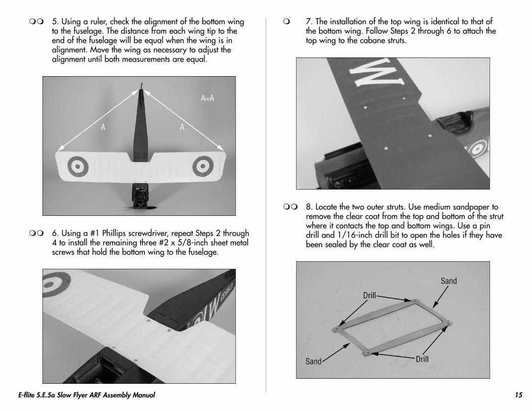
5. Using a ruler, check the alignment of the bottom wing to the fuselage. The distance from each wing tip to the end of the fuselage will be equal when the wing is in alignment. Move the wing as necessary to adjust the alignment until both measurements are equal.
6. Using a #1 Phillips screwdriver, repeat Steps 2 through 4 to install the remaining three #2 x 5/8-inch sheet metal screws that hold the bottom wing to the fuselage.
7. The installation of the top wing is identical to that of the bottom wing. Follow Steps 2 through 6 to attach the top wing to the cabane struts.
8. Locate the two outer struts. Use medium sandpaper to remove the clear coat from the top and bottom of the strut where it contacts the top and bottom wings. Use a pin drill and 1/16-inch drill bit to open the holes if they have been sealed by the clear coat as well.

16 E-flite S.E.5a Slow Flyer ARF Assembly Manual
9. Position the outer strut between the top and bottom wings as shown. Use foam-safe CA to glue the outer strut to the top and bottom wings.
10. Repeat Steps 8 and 9 to install the remaining outer strut between the top and bottom wings.
Attach the Fin and StabilizerRequired Parts
• Rudder/Fin • Elevator/Stabilizer• Micro control horn (2) • Micro control horn backplate (2)
Required Tools and Adhesives• Square • Foam-safe CA• Sandpaper
1. Position the rudder/fin tab into the slot in the stabilizer/elevator. The green side of the stabilizer/elevator faces the rudder/fin. Use a square and foam-safe CA to glue the two items together, making sure the rudder/fin is square to the stabilizer/elevator.
17E-flite S.E.5a Slow Flyer ARF Assembly Manual
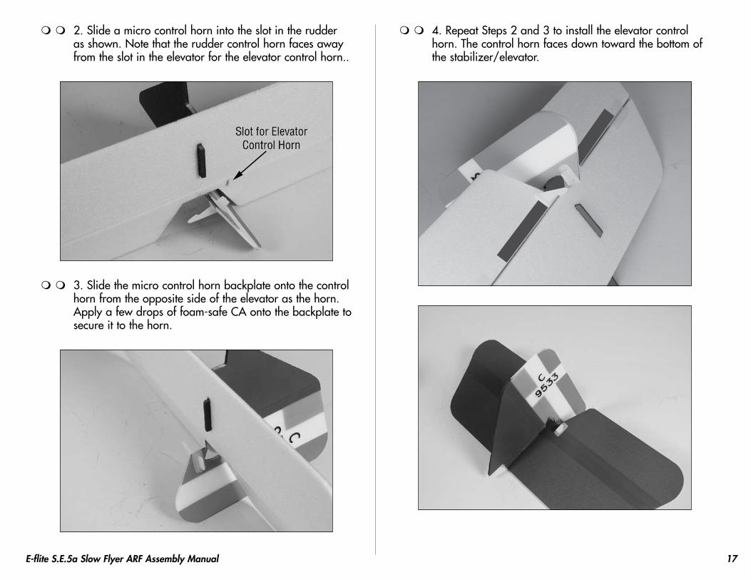
2. Slide a micro control horn into the slot in the rudder as shown. Note that the rudder control horn faces away from the slot in the elevator for the elevator control horn..
3. Slide the micro control horn backplate onto the control horn from the opposite side of the elevator as the horn. Apply a few drops of foam-safe CA onto the backplate to secure it to the horn.
4. Repeat Steps 2 and 3 to install the elevator control horn. The control horn faces down toward the bottom of the stabilizer/elevator.
18 E-flite S.E.5a Slow Flyer ARF Assembly Manual
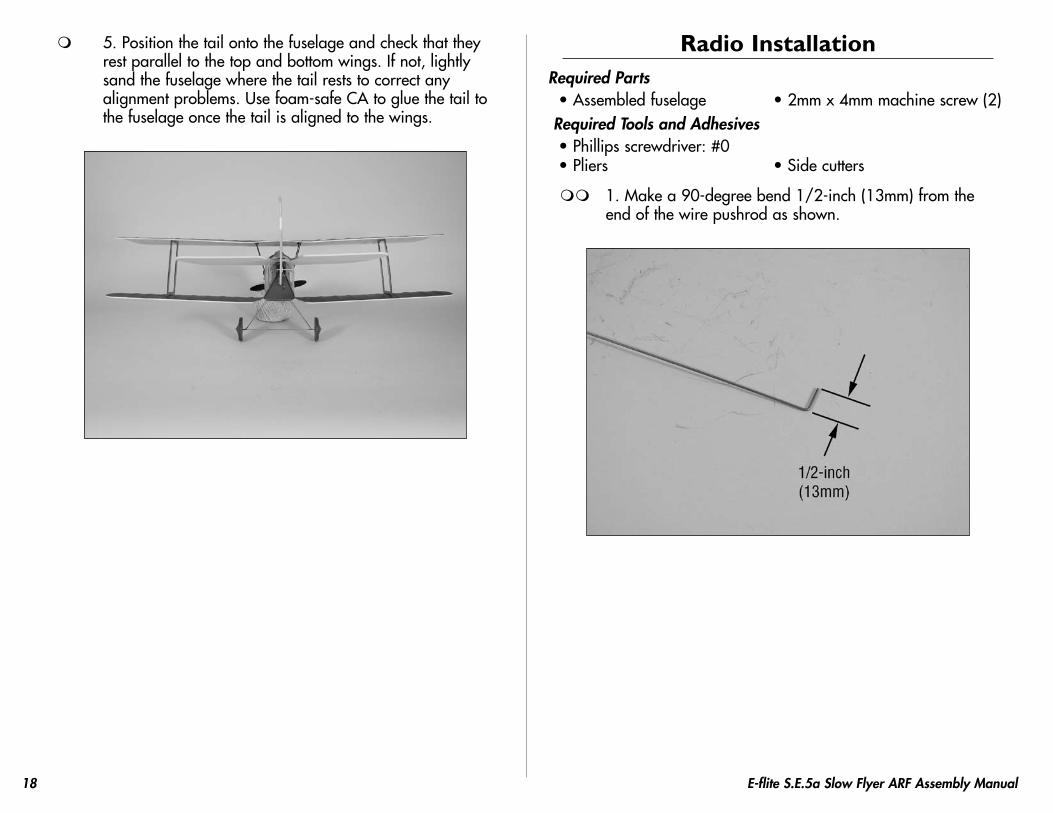
5. Position the tail onto the fuselage and check that they rest parallel to the top and bottom wings. If not, lightly sand the fuselage where the tail rests to correct any alignment problems. Use foam-safe CA to glue the tail to the fuselage once the tail is aligned to the wings.
Radio InstallationRequired Parts
• Assembled fuselage • 2mm x 4mm machine screw (2) Required Tools and Adhesives
• Phillips screwdriver: #0• Pliers • Side cutters
1. Make a 90-degree bend 1/2-inch (13mm) from the end of the wire pushrod as shown.
19E-flite S.E.5a Slow Flyer ARF Assembly Manual
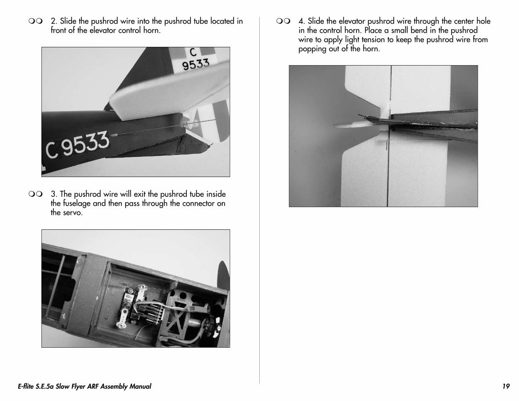
2. Slide the pushrod wire into the pushrod tube located in front of the elevator control horn.
3. The pushrod wire will exit the pushrod tube inside the fuselage and then pass through the connector on the servo.
4. Slide the elevator pushrod wire through the center hole in the control horn. Place a small bend in the pushrod wire to apply light tension to keep the pushrod wire from popping out of the horn.
20 E-flite S.E.5a Slow Flyer ARF Assembly Manual
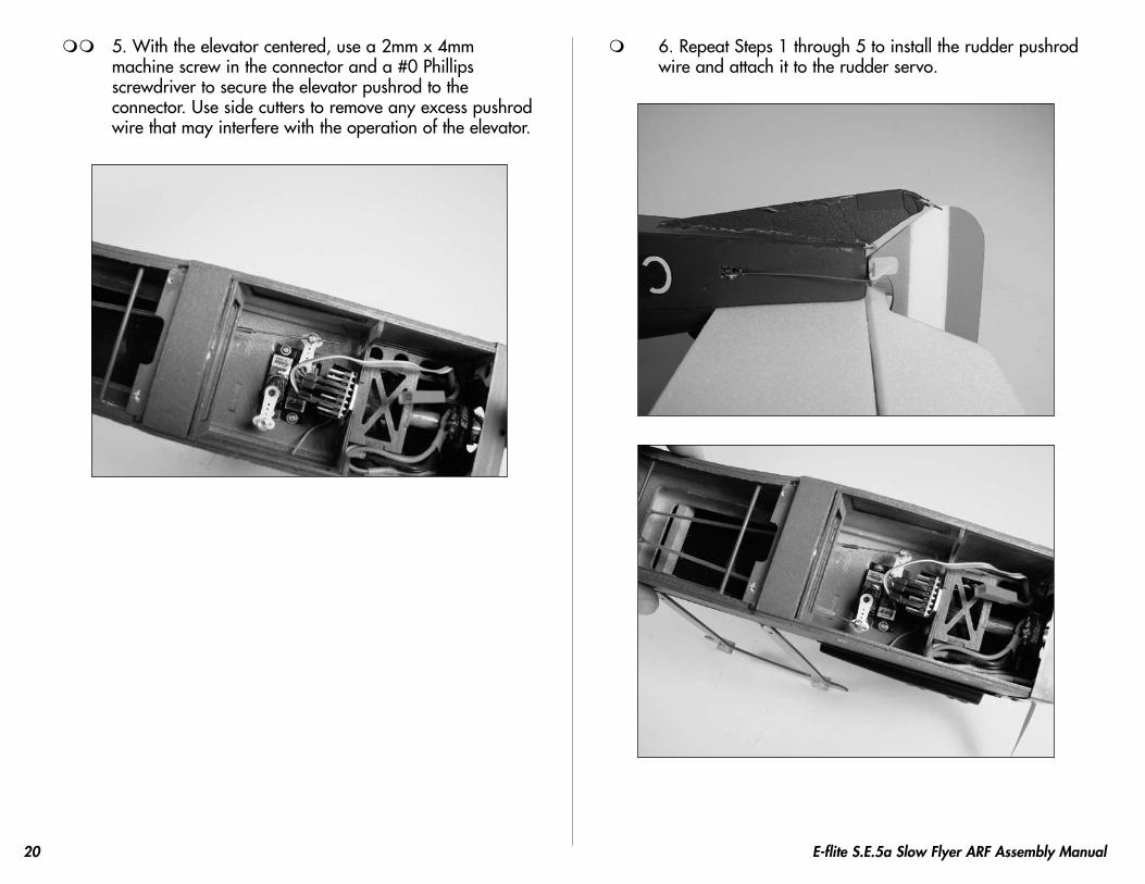
5. With the elevator centered, use a 2mm x 4mm machine screw in the connector and a #0 Phillips screwdriver to secure the elevator pushrod to the connector. Use side cutters to remove any excess pushrod wire that may interfere with the operation of the elevator.
6. Repeat Steps 1 through 5 to install the rudder pushrod wire and attach it to the rudder servo.
21E-flite S.E.5a Slow Flyer ARF Assembly Manual
Landing Gear InstallationRequired Parts
• Airframe • Landing gear• Wheel (2) • Wheel retainer (2)
Required Tools and Adhesives• Foam-safe CA Hobby knife
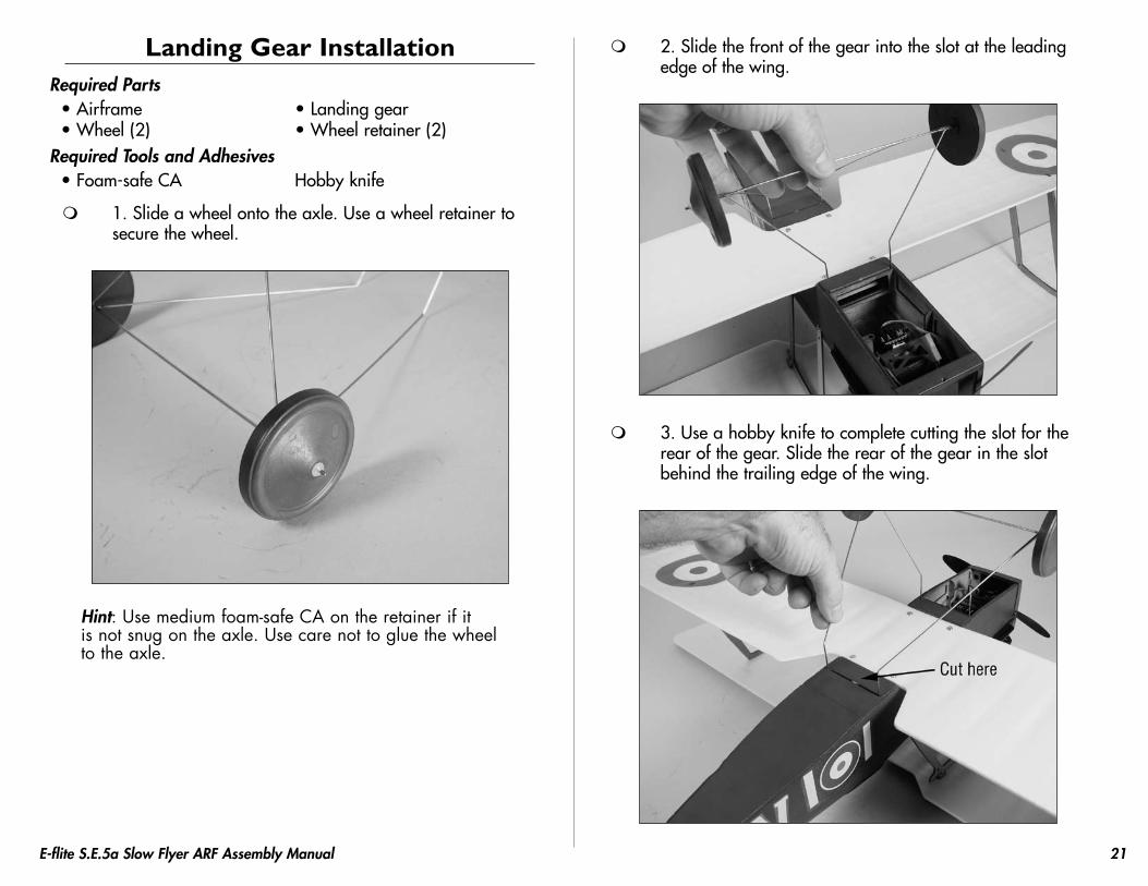
1. Slide a wheel onto the axle. Use a wheel retainer to secure the wheel.
Hint: Use medium foam-safe CA on the retainer if it is not snug on the axle. Use care not to glue the wheel to the axle.
2. Slide the front of the gear into the slot at the leading edge of the wing.
3. Use a hobby knife to complete cutting the slot for the rear of the gear. Slide the rear of the gear in the slot behind the trailing edge of the wing.

22 E-flite S.E.5a Slow Flyer ARF Assembly Manual
4. Carefully press the gear into the slots at the front and rear into the fuselage.
Note: You may put a drop of foam-safe CA at each corner of the fuselage where the landing gear exits to help secure it to the airframe.
Wing Rigging InstallationRequired Parts
• Airframe • Rigging thread Required Tools and Adhesives
• Foam-safe CA • Thin CA• Needle • Hobby knife
Note: Installing the rigging will add to the appearance and strength of your airplane, but you will not be able to remove the wings without cutting the rigging. The rigging is required on your S.E.5a. DO NOT fly your model before installing the rigging.
Hint A: You may want to thread the rigging through a needle to make it easier to pass the rigging through the holes, especially the tubes in the fuselage near the bottom wing.
Hint B: Another option is to soak the last 2 inches (50mm) of the rigging line with thin CA to stiffen it up so you can pass it through all the holes.
23E-flite S.E.5a Slow Flyer ARF Assembly Manual
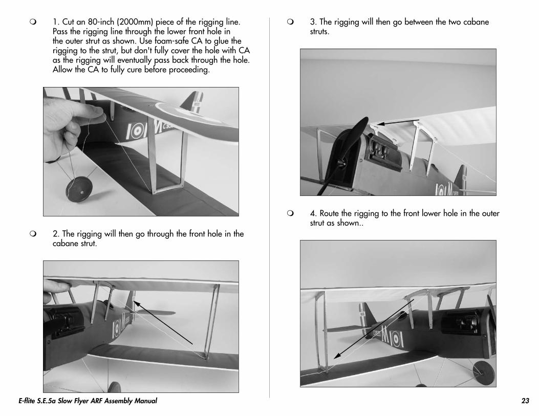
1. Cut an 80-inch (2000mm) piece of the rigging line.Pass the rigging line through the lower front hole in the outer strut as shown. Use foam-safe CA to glue the rigging to the strut, but don't fully cover the hole with CA as the rigging will eventually pass back through the hole. Allow the CA to fully cure before proceeding.
2. The rigging will then go through the front hole in the cabane strut.
3. The rigging will then go between the two cabane struts.
4. Route the rigging to the front lower hole in the outer strut as shown..
24 E-flite S.E.5a Slow Flyer ARF Assembly Manual
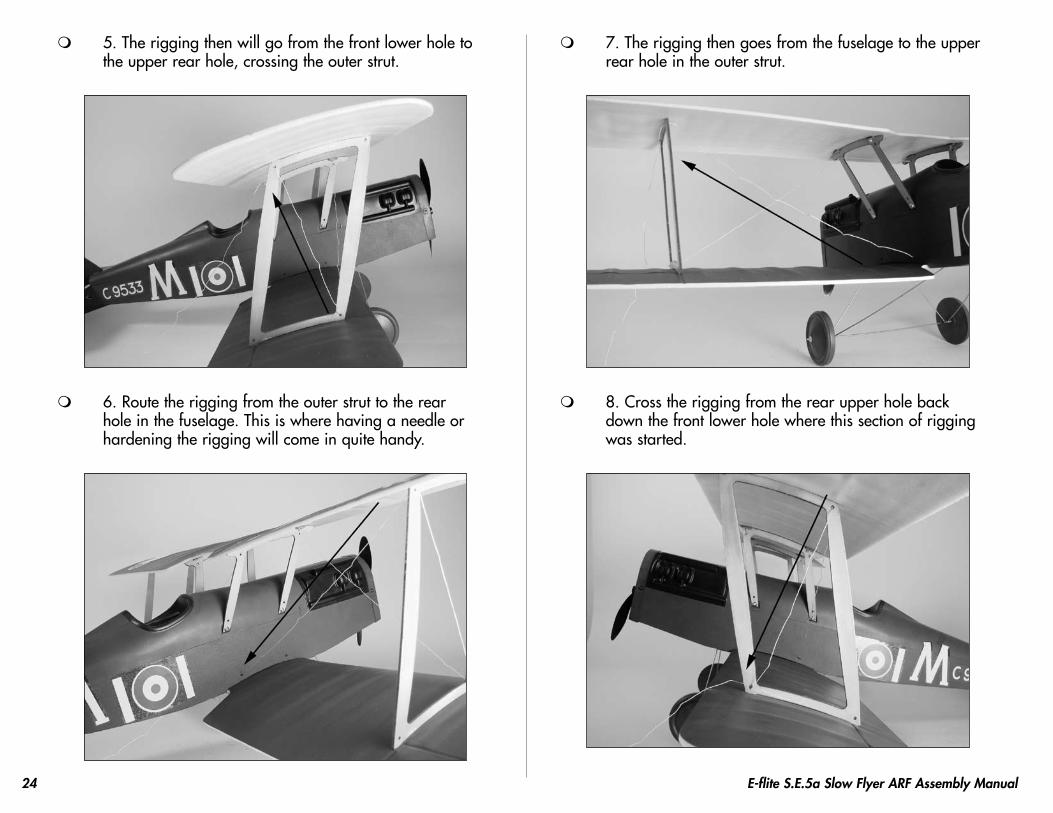
5. The rigging then will go from the front lower hole to the upper rear hole, crossing the outer strut.
6. Route the rigging from the outer strut to the rear hole in the fuselage. This is where having a needle or hardening the rigging will come in quite handy.
7. The rigging then goes from the fuselage to the upper rear hole in the outer strut.
8. Cross the rigging from the rear upper hole back down the front lower hole where this section of rigging was started.
25E-flite S.E.5a Slow Flyer ARF Assembly Manual
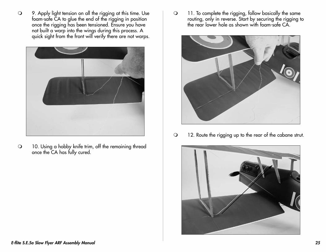
9. Apply light tension on all the rigging at this time. Use foam-safe CA to glue the end of the rigging in position once the rigging has been tensioned. Ensure you have not built a warp into the wings during this process. A quick sight from the front will verify there are not warps.
10. Using a hobby knife trim, off the remaining thread once the CA has fully cured.
11. To complete the rigging, follow basically the same routing, only in reverse. Start by securing the rigging to the rear lower hole as shown with foam-safe CA.
12. Route the rigging up to the rear of the cabane strut.
26 E-flite S.E.5a Slow Flyer ARF Assembly Manual
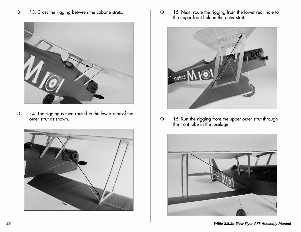
13. Cross the rigging between the cabane struts.
14. The rigging is then routed to the lower rear of the outer strut as shown.
15. Next, route the rigging from the lower rear hole to the upper front hole in the outer strut.
16. Run the rigging from the upper outer strut through the front tube in the fuselage.
27E-flite S.E.5a Slow Flyer ARF Assembly Manual
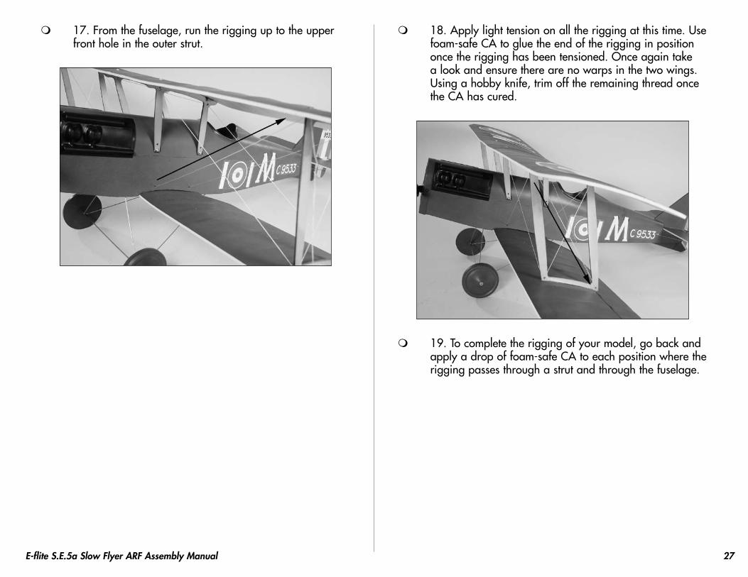
17. From the fuselage, run the rigging up to the upper front hole in the outer strut.
18. Apply light tension on all the rigging at this time. Use foam-safe CA to glue the end of the rigging in position once the rigging has been tensioned. Once again take a look and ensure there are no warps in the two wings. Using a hobby knife, trim off the remaining thread once the CA has cured.
19. To complete the rigging of your model, go back and apply a drop of foam-safe CA to each position where the rigging passes through a strut and through the fuselage.

28 E-flite S.E.5a Slow Flyer ARF Assembly Manual
Machine Gun Installation Required Parts
Completed airframeMachine gun
Required Tools and AdhesivesFoam-safe CA
1. Using foam-safe CA, install the machine gun on the top wing. The tabs on the gun will align with the slots in the top wing.
Control Throws
1. Turn on the transmitter and receiver of your aircraft. Check the movement of the rudder using the transmitter. When the stick is moved right, the rudder should also move right. Reverse the direction of the servo at the transmitter if necessary.
2. Check the movement of the elevator with the radio system. Moving the elevator stick down will make the airplane elevator move up.
Elevator3/4-inch (19mm) up/down
Rudder11/2-inch (38mm) left/right
29E-flite S.E.5a Slow Flyer ARF Assembly Manual
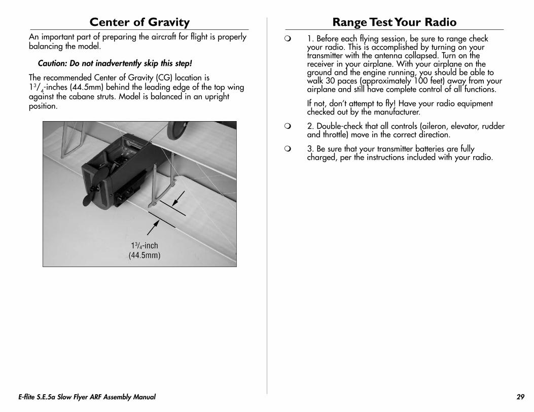
Center of GravityAn important part of preparing the aircraft for flight is properly balancing the model.
Caution: Do not inadvertently skip this step!
The recommended Center of Gravity (CG) location is 13/4-inches (44.5mm) behind the leading edge of the top wing against the cabane struts. Model is balanced in an upright position.
Range Test Your Radio 1. Before each flying session, be sure to range check
your radio. This is accomplished by turning on your transmitter with the antenna collapsed. Turn on the receiver in your airplane. With your airplane on the ground and the engine running, you should be able to walk 30 paces (approximately 100 feet) away from your airplane and still have complete control of all functions.
If not, don’t attempt to fly! Have your radio equipment checked out by the manufacturer.
2. Double-check that all controls (aileron, elevator, rudder and throttle) move in the correct direction.
3. Be sure that your transmitter batteries are fully charged, per the instructions included with your radio.
30 E-flite S.E.5a Slow Flyer ARF Assembly Manual
PreflightCheck Your Radio
Before going to the field, be sure that your batteries are fully charged per the instructions included with your radio. Charge both the transmitter and receiver pack for your airplane. Use the recommended charger supplied with your particular radio system, following the instructions provided with the radio. In most cases, the radio should be charged the night before going out flying.
Before each flying session, be sure to range check your radio. See your radio manual for the recommended range and instructions for your radio system. Each radio manufacturer specifies different procedures for their radio systems. Next, start the motor. With the model securely anchored, check the range again. The range test should not be significantly affected. If it is, don’t attempt to fly! Have your radio equipment checked out by the manufacturer.
Note: Keep loose items that can get entangled in the propeller away from the prop. These include loose clothing, or other objects such as pencils and screwdrivers. Especially keep your hands away from the propeller.
Double-check that all controls (aileron, elevator, rudder and throttle) move in the correct direction.
Check the radio installation and make sure all the control surfaces are moving correctly (i.e. the correct direction and with the recommended throws). Test run the motor and make sure it transitions smoothly from off to full throttle and back. Also ensure the engine is installed according to the manufacturer’s instructions, and it will operate consistently.
Check all the control horns, servo horns, and clevises to make sure they are secure and in good condition. Replace any items that would be considered questionable. Failure of any of these components in flight would mean the loss of your aircraft.
Flying the S.E.5a Slow Flyer
You will find the S.E.5a Slow Flyer to be a solid, honest-flying model.
Ensure your CG is set according to the manual and power up the aircraft. Move your throttle trim up slowly until the motor just begins to spin. This will be your flight idle that will help to establish a longer glide path and tends to make landings easier. Before taxiing out to the runway, double-check all controls are working in the correct direction and functioning properly. You will find the rudder very effective; on the ground, tracking is very predictable. Apply power smoothly and begin the takeoff roll. Correct with rudder as necessary and apply up elevator slowly until the model lifts off.
You will find flying the S.E.5a to be very relaxing and easy. The model is not designed for high speed flight. Most flight is accomplished below half throttle and will yield flights in excess of 15 minutes with a 480 2-cell battery with a Park 250 when outfitted with the GWS 6x5 slow flyer prop. Landing the S.E.5a Slow Flyer is as easy as setting up on final approach, lowering the throttle to idle and gliding in to a soft touch-down.
Note: You will find the SE5a capable of basic loops and stall turns. Flying these manuevers is easy and fun with the SE5a. After your first flight you will want to check your rigging to ensure none of the locations that were CA'ed have let loose. Check these areas on a regular basis to ensure safe and reliable operation.. We hope you enjoy the experience of flying the S.E.5a Slow Flyer.
Happy landings.
31E-flite S.E.5a Slow Flyer ARF Assembly Manual
2007 Official AMA National Model Aircraft Safety Code
GENERAL1) I will not fly my model aircraft in sanctioned events, air shows
or model flying demonstrations until it has been proven to be airworthy by having been previously, successfully flight tested.
2) I will not fly my model higher than approximately 400 feet within 3 miles of an airport without notifying the airport operator. I will give right-of-way and avoid flying in the proximity of full-scale aircraft. Where necessary, an observer shall be utilized to supervise flying to avoid having models fly in the proximity of full-scale aircraft.
3) Where established, I will abide by the safety rules for the flying site I use, and I will not willfully or deliberately fly my models in a careless, reckless and/or dangerous manner.
4) The maximum takeoff weight of a model is 55 pounds, except models flown under Experimental Aircraft rules.
5) I will not fly my model unless it is identified with my name and address or AMA number on or in the model. (This does not apply to models while being flown indoors.)
6) I will not operate models with metal-bladed propellers or with gaseous boosts, in which gases other than air enter their internal combustion engine(s); nor will I operate models with extremely hazardous fuels such as those containing tetranitromethane or hydrazine.
RADIO CONTROL1) I will have completed a successful radio equipment ground range
check before the first flight of a new or repaired model.2) I will not fly my model aircraft in the presence of spectators until I
become a qualified flier, unless assisted by an experienced helper.3) At all flying sites a straight or curved line(s) must be established
in front of which all flying takes place with the other side for spectators. Only personnel involved with flying the aircraft are allowed at or in front of the flight line. Intentional flying behind the flight line is prohibited.
4) I will operate my model using only radio control frequencies currently allowed by the Federal Communications Commission. (Only properly licensed Amateurs are authorized to operate equipment on Amateur Band frequencies.)
5) Flying sites separated by three miles or more are considered safe from site-to-site interference, even when both sites use the same frequencies. Any circumstances under three miles separation require a frequency management arrangement, which may be either an allocation of specific frequencies for each site or testing to determine that freedom from interference exists. Allocation plans or interference test reports shall be signed by the parties involved and provided to AMA Headquarters.
Documents of agreement and reports may exist between (1) two or more AMA Chartered Clubs, (2) AMA clubs and individual AMA members not associated with AMA Clubs, or (3) two or more individual AMA members.
6) For Combat, distance between combat engagement line and spectator line will be 500 feet per cubic inch of engine displacement. (Example: .40 engine = 200 feet.); electric motors will be based on equivalent combustion engine size. Additional safety requirements will be per the RC Combat section of the current Competition Regulations.
7) At air shows or model flying demonstrations, a single straight line must be established, one side of which is for flying, with the other side for spectators.
8) With the exception of events flown under AMA Competition rules, after launch, except for pilots or helpers being used, no powered model may be flown closer than 25 feet to any person.
9) Under no circumstances may a pilot or other person touch a powered model in flight.

11036
© 2007 Horizon Hobby, Inc. 4105 Fieldstone Road
Champaign, Illinois 61822 (877) 504-0233
horizonhobby.com E-fliteRC.com