Embed Size (px)
Citation preview

2012 SEATTLE MECHANICAL CODE 33
CHAPTER 4
VENTILATION
SECTION 401GENERAL
401.1 Scope. This chapter shall govern the ventilation ofspaces within a building intended to be occupied. Mechanicalexhaust systems, including exhaust systems serving clothesdryers and cooking appliances; hazardous exhaust systems;dust, stock and refuse conveyor systems; subslab soil exhaustsystems; smoke control systems; energy recovery ventilationsystems and other systems specified in Section 502 shallcomply with Chapter 5.
401.2 Ventilation required. Every occupied space other thanenclosed parking garages, loading docks and motor vehiclerepair garages shall be ventilated in accordance with Section401.2.1 or 401.2.2. Enclosed parking garages, loading docksand motor vehicle repair garages shall be ventilated bymechanical means in accordance with Sections 403 and 404.
[W] 401.2.1 Group R occupancies. Ventilation in GroupR occupancies shall be provided in accordance with Sec-tions 403.8 and 403.9.
401.2.2 All other occupancies. Ventilation in all otheroccupancies shall be provided by natural means in accor-dance with Section 402 or by mechanical means in accor-dance with Section 403. ((Where the air infiltration rate ina dwelling unit is less than 5 air changes per hour whentested with a blower door at a pressure of 0.2-inch watercolumn (50 Pa) in accordance with Section 402.4.1.2 ofthe International Energy Conservation Code, the dwellingunit shall be ventilated by mechanical means in accor-dance with Section 403.))
401.3 When required. Ventilation shall be provided duringthe periods that the room or space is occupied.
401.4 Intake opening location. Air intake openings shallcomply with all of the following:
1. Intake openings shall be located a minimum of 10 feet(3048 mm) from lot lines or buildings on the same lot.Where openings front on a street or public way, the dis-tance shall be measured from the opposite side of thestreet or public way.
2. Mechanical and gravity outdoor air intake openingsshall be located not less than 10 feet (3048 mm) hori-zontally from any hazardous or noxious contaminantsource, such as vents, streets, alleys, parking lots andloading docks, except as specified in Item 3 or Section501.3.1. Outdoor air intake openings shall be permittedto be located less than 10 feet (3048 mm) horizontallyfrom streets, alleys, parking lots and loading docks pro-vided that the openings are located not less than 25 feet(7620 mm) vertically above such locations. Whereopenings front on a street or public way, the distanceshall be measured from the closest edge of the street orpublic way. The exhaust from a bathroom, clothes
dryer or kitchen in a dwelling shall not be considered tobe a hazardous or noxious contaminant.
Exception: Enclosed parking garage and repairgarage intakes are permitted to be located less than10 feet horizontally of the street, alley, parking lotsand loading docks.
3. Intake openings shall be located not less than 3 feet(914 mm) below contaminant sources where suchsources are located within 10 feet (3048 mm) of theopening.
4. Intake openings on structures in flood hazard areasshall be at or above the elevation required by Section1612 of the International Building Code for utilitiesand attendant equipment.
5. Intake openings shall not be located:
5.1. In a crawl space;
5.2. Less than one foot (305 mm) above a roof, adja-cent grade, or other surface directly below theintake; or
5.3. Under a deck having a surface height less thanthree feet above grade or other surface directlybelow the intake.
401.5 Intake opening protection. Air intake openings thatterminate outdoors shall be protected with corrosion-resistantscreens, louvers or grilles. Openings in louvers, grilles andscreens shall be sized in accordance with Table 401.5, andshall be protected against local weather conditions. Louversthat protect air intake openings in structures located in hurri-cane-prone regions, as defined in the International BuildingCode, shall comply with AMCA 550. Outdoor air intakeopenings located in exterior walls shall meet the provisionsfor exterior wall opening protectives in accordance with theInternational Building Code.
TABLE 401.5OPENING SIZES IN LOUVERS, GRILLES
AND SCREENS PROTECTING AIR INTAKE OPENINGS
For SI: 1 inch = 25.4 mm.
OUTDOOR OPENING TYPE
MINIMUM AND MAXIMUM OPENING SIZES IN LOUVERS, GRILLES AND
SCREENS MEASURED IN ANY DIRECTION
Intake openings in residential occupancies
Not < 1/4 inch and not > 1/2 inch
Intake openings in other than residential occupancies
> 1/4 inch and not > 1 inch
Interpretation: For purposes of this section, lot lineincludes any property line separating one lot from anotherlot, but does not include any property line separating a lotfrom a public street or alley right-of-way.
04_Seattle_Mech_2012.fm Page 33 Wednesday, November 13, 2013 1:25 PM

VENTILATION
34 2012 SEATTLE MECHANICAL CODE
401.6 Contaminant sources. Stationary local sources pro-ducing airborne particulates, heat, odors, fumes, spray,vapors, smoke or gases in such quantities as to be irritating orinjurious to health shall be provided with an exhaust systemin accordance with Chapter 5 or a means of collection andremoval of the contaminants. Such exhaust shall dischargedirectly to an approved location at the exterior of the build-ing.
401.7 Compliance and commissioning. Compliance withSections 402 and 403.1 through 403.8 shall be demonstratedthrough engineering calculations. Documentation of calcula-tions shall be submitted on the permit plan sets. Testing andcommissioning shall be performed and documented in accor-dance with the International Energy Conservation Code.
SECTION 402NATURAL VENTILATION
[B] 402.1 Natural ventilation. Natural ventilation of anoccupied space shall be through windows, doors, louvers orother openings to the outdoors. The operating mechanism forsuch openings shall be provided with ready access so that theopenings are readily controllable by the building occupants.
Exception: Automatically controlled natural ventilationsystems do not require ready access and control by build-ing occupants.
[B] 402.2 Ventilation area required. The minimum open-able area to the outdoors shall be 4 percent of the floor areabeing ventilated.
[B] 402.3 Adjoining spaces. Where rooms and spaces with-out openings to the outdoors are ventilated through an adjoin-ing room, the opening to the adjoining rooms shall beunobstructed and shall have an area not less than 8 percent ofthe floor area of the interior room or space, but not less than25 square feet (2.3 m2). The minimum openable area to theoutdoors shall be based on the total floor area being venti-lated.
Exception: Exterior openings required for ventilationshall be permitted to open into a thermally isolated sun-room addition or patio cover, provided that the openablearea between the sunroom addition or patio cover and theinterior room has an area of not less than 8 percent of thefloor area of the interior room or space, but not less than20 square feet (1.86 m2). The minimum openable area tothe outdoors shall be based on the total floor area beingventilated.
[B] 402.4 Openings below grade. Where openings belowgrade provide required natural ventilation, the outside hori-zontal clear space measured perpendicular to the openingshall be one and one-half times the depth of the opening. Thedepth of the opening shall be measured from the averageadjoining ground level to the bottom of the opening.
SECTION 403MECHANICAL VENTILATION
403.1 Ventilation system. Mechanical ventilation shall beprovided by a method of supply air and return or exhaust air.The amount of supply air shall be approximately equal to theamount of return and exhaust air. The system shall not beprohibited from producing negative or positive pressure. Thesystem to convey ventilation air shall be designed andinstalled in accordance with Chapter 6.
[W] 403.2 Outdoor air required. The minimum outdoor air-flow rate shall be determined in accordance with Section403.3. ((Ventilation supply systems shall be designed todeliver the required rate of outdoor airflow to the breathingzone within each occupiable space.))
[W] Exceptions:
1. Where the registered design professional demon-strates that an engineered ventilation system designwill prevent the maximum concentration of contam-inants from exceeding that obtainable by the rate ofoutdoor air ventilation determined in accordancewith Section 403.3, the minimum required rate ofoutdoor air shall be reduced in accordance with suchengineered system design.
2. Alternate systems designed in accordance withASHRAE Standard 62.1 Section 6.2, VentilationRate Procedure shall be permitted.
[W] 403.2.1 Recirculation of air. The ((outdoor)) airrequired by Section 403.3 shall not be recirculated. Air inexcess of that required by Section 403.3 shall not be pro-hibited from being recirculated as a component of supplyair to building spaces, except that:
1. Ventilation air shall not be recirculated from onedwelling to another or to dissimilar occupancies.
2. Supply air to a swimming pool and associated deckareas shall not be recirculated unless such air isdehumidified to maintain the relative humidity ofthe area at 60 percent or less. Air from this area shallnot be recirculated to other spaces where ((morethan)) 10 percent or more of the resulting supply air-stream consists of air recirculated from these spaces.
3. Where mechanical exhaust is required by Note b inTable 403.3, recirculation of air from such spacesshall be prohibited. All air supplied to such spacesshall be exhausted, including any air in excess ofthat required by Table 403.3.
4. Building HVAC air used as transfer air for heatremoval may be recirculated. ((Where mechanicalexhaust is required by Note g in Table 403.3,mechanical exhaust is required and recirculation isprohibited where more than 10 percent of the result-ing supply airstream consists of air recirculated fromthese spaces.))
ñ
04_Seattle_Mech_2012.fm Page 34 Wednesday, November 13, 2013 1:25 PM

VENTILATION
2012 SEATTLE MECHANICAL CODE 35
403.2.2 Transfer air. Except where recirculation fromsuch spaces is prohibited by Table 403.3, air transferredfrom occupiable spaces is not prohibited from serving asmakeup air for required exhaust systems in such spaces askitchens, baths, toilet rooms, elevators and smokinglounges. The amount of transfer air and exhaust air shallbe sufficient to provide the flow rates as specified in Sec-tion 403.3. The required outdoor airflow rates specified inTable 403.3 shall be introduced directly into such spacesor into the occupied spaces from which air is transferred ora combination of both.
403.2.3 Outdoor air delivery. The outdoor air shall beducted in a fully enclosed path directly to every air-han-dling unit in each zone not provided with sufficient opera-ble opening area for natural ventilation to occur.
Exception: Ducts may terminate within 12 inches ofthe intake to an HVAC unit if they are physically fas-tened so that the outdoor air duct is directed into theunit intake.
403.3 Outdoor airflow rate. Ventilation systems shall bedesigned to have the capacity to supply the minimum outdoorairflow rate determined in accordance with this section. Theoccupant load utilized for design of the ventilation systemshall not be less than the number determined from the esti-mated maximum occupant load rate indicated in Table 403.3.Ventilation rates for occupancies not represented in Table403.3 shall be those for a listed occupancy classification thatis most similar in terms of occupant density, activities andbuilding construction; or shall be determined by an approvedengineering analysis. The ventilation system shall bedesigned to supply the required rate of ventilation air contin-uously during the period the building is occupied, except asotherwise stated in other provisions of the code.
With the exception of smoking lounges, the ventilationrates in Table 403.3 are based on the absence of smoking inoccupiable spaces. Where smoking is anticipated in a spaceother than a smoking lounge, the ventilation system servingthe space shall be designed to provide ventilation over andabove that required by Table 403.3 in accordance withaccepted engineering practice.
[W] Exception: ((The occupant load is not required to bedetermined based on the estimated maximum occupantload rate indicated in Table 403.3 where approved statisti-cal data document the accuracy of an alternate anticipatedoccupant density.)) Where occupancy density is knownand documented in the plans, the outside air rate may bebased on the design occupant density. Under no circum-stance shall the occupancies used result in outside air lessthan one-half that resulting from application of Table403.3 estimated maximum occupancy rates.
403.3.1 Zone outdoor airflow. The minimum outdoor air-flow required to be supplied to each zone shall be deter-
mined as a function of occupancy classification and spaceair distribution effectiveness in accordance with Sections403.3.1.1 through 403.3.1.3.
403.3.1.1 Breathing zone outdoor airflow. The out-door airflow rate required in the breathing zone (Vbz) ofthe occupiable space or spaces in a zone shall be deter-mined in accordance with Equation 4-1.
(Equation 4-1)
where:
Az = Zone floor area: the net occupiable floor area ofthe space or spaces in the zone.
Pz = Zone population: the number of people in thespace or spaces in the zone.
Rp = People outdoor air rate: the outdoor airflow raterequired per person from Table 403.3.
Ra = Area outdoor air rate: the outdoor airflow raterequired per unit area from Table 403.3.
403.3.1.2 Zone air distribution effectiveness. Thezone air distribution effectiveness (Ez) shall be deter-mined using Table 403.3.1.2.
TABLE 403.3.1.2ZONE AIR DISTRIBUTION EFFECTIVENESSa,b,c,d,e
For SI: 1 foot = 304.8 mm, 1 foot per minute = 0.00506 m/s,°C = [(°F) – 32]/1.8.
a. “Cool air” is air cooler than space temperature. b. “Warm air” is air warmer than space temperature. c. “Ceiling” includes any point above the breathing zone. d. “Floor” includes any point below the breathing zone. e. “Makeup air” is air supplied or transferred to a zone to replace air
removed from the zone by exhaust or return systems. f. Zone air distribution effectiveness of 1.2 shall be permitted for systems
with a floor supply of cool air and ceiling return, provided that low-velocity displacement ventilation achieves unidirectional flow andthermal stratification.
g. Zone air distribution effectiveness of 1.0 shall be permitted for systemswith a ceiling supply of warm air, provided that supply air temperature isless than 15°F above space temperature and provided that the 150 foot-per-minute supply air jet reaches to within 41/2 feet of floor level.
AIR DISTRIBUTION CONFIGURATION Ez
Ceiling or floor supply of cool air 1.0f
Ceiling or floor supply of warm air and floor return 1.0
Ceiling supply of warm air and ceiling return 0.8g
Floor supply of warm air and ceiling return 0.7
Makeup air drawn in on the opposite side of the room from the exhaust and/or return 0.8
Makeup air drawn in near to the exhaust and/or return location 0.5
Vbz RpPz RaAz+=
04_Seattle_Mech_2012.fm Page 35 Wednesday, November 13, 2013 1:25 PM

VENTILATION
36 2012 SEATTLE MECHANICAL CODE
[W] TABLE 403.3MINIMUM VENTILATION RATES
(continued)
OCCUPANCY CLASSIFICATION OCCUPANT DENSITY#/1000 FT2 a
PEOPLE OUTDOOR AIRFLOW RATE IN BREATHING ZONE,
Rp CFM/PERSON
AREA OUTDOOR AIRFLOW RATE IN BREATHING ZONE,
Ra CFM/FT2 a
EXHAUST AIRFLOW RATE
CFM/FT2 a
Correctional facilities
Cells without plumbing fixtures 25 5 0.12 —
with plumbing fixturesg, k 25 5 0.12 1.0
Dining halls (see food and beverage service)
— — — —
Guard stations 15 5 0.06 —
Day room 30 5 0.06 —
Booking/waiting 50 7.5 0.06 —
Dry cleaners, laundries
Coin-operated dry cleaner 20 15 — —
Coin-operated laundries 20 7.5 0.06 —
Commercial dry cleaner 30 30 — —
Commercial laundry 10 25 — —
Storage, pick up 30 7.5 0.12 —
Education
Auditoriums 150 5 0.06 —
Corridors (see public spaces) — — — —
Media center 25 10 0.12 —
Sports locker roomsg, k — — — 0.5
Music/theater/dance 35 10 0.06 —
((Smoking loungesb 70 60 —))
Day care (through age 4) 25 10 0.18 —
Classrooms (ages 5-8) 25 10 0.12 —
Classrooms (age 9 plus) 35 10 0.12 —
Lecture classroom 65 7.5 0.06 —
Lecture hall (fixed seats) 150 7.5 0.06 —
Art classroomg 20 10 0.18 0.7
Science laboratoriesg, k 25 10 0.18 1.0
Wood/metal shopsg, k 20 10 0.18 0.5
Computer lab 25 10 0.12 —
Multiuse assembly 100 7.5 0.06 —
Locker/dressing roomsg, k — — — 0.25
Food and beverage service
Bars, cocktail lounges 100 7.5 0.18 —
Cafeteria, fast food 100 7.5 0.18 —
Dining rooms 70 7.5 0.18 —
Kitchens (cooking)b — — — 0.7
Hospitals, nursing and convalescent homes
Autopsy roomsb — — — 0.5
Medical procedure rooms 20 15 — —
Operating rooms 20 30 — —
Patient rooms 10 25 — —
Physical therapy 20 15 — —
Recovery and ICU 20 15 — —
04_Seattle_Mech_2012.fm Page 36 Wednesday, November 13, 2013 1:25 PM

VENTILATION
2012 SEATTLE MECHANICAL CODE 37
[W] TABLE 403.3—continuedMINIMUM VENTILATION RATES
(continued)
OCCUPANCY CLASSIFICATION OCCUPANT DENSITY#/1000 FT2 a
PEOPLE OUTDOOR AIRFLOW RATE IN BREATHING ZONE,
Rp CFM/PERSON
AREA OUTDOOR AIRFLOW RATE IN BREATHING ZONE,
Ra CFM/FT2 a
EXHAUST AIRFLOW RATE
CFM/FT2 a
Hotels, motels, resorts and dormitories
Multipurpose assembly 120 5 0.06 —
Bathrooms/toilet—privateg, k — — — 25/50f
Bedroom/living room 10 5 0.06 —
Conference/meeting 50 5 0.06 —
Dormitory sleeping areas 20 5 0.06 —
Gambling casinos 120 7.5 0.18 —
Lobbies/prefunction 30 7.5 0.06 —
Offices
Conference rooms 50 5 0.06 —
[W] Kitchenettes — — — 0.30
Office spaces 5 5 0.06 —
Reception areas 30 5 0.06 —
Telephone/data entry 60 5 0.06 —
Main entry lobbies 10 5 0.06 —
[W] Private dwellings, single and multiple
Garages, common for multiple unitsb — — — 0.75
Garages, separate for each dwellingb — — — 100 cfm per car
Kitchensb — — — 25/100f
Living areasc Based upon number of bed-
rooms. First bedroom, 2; each additional bedroom, 1
((0.35 ACH but not less than 15 cfm/person))
See Tables 403.8.1and 403.8.5.1
— —
Toilet rooms, ((and)) bathroomsk and laundry areasg, i — — — 20/50f
Public spaces
Corridors — — 0.06 —
Elevator car — — — 1.0
Elevator lobbies in garages — — 1.0 —
Shower room (per shower head)g, k — — — 50/20f
((Smoking loungesb 70 60 — —))
Toilet rooms — publicg, k — — — 50/70e
Places of religious worship 120 5 0.06 —
Courtrooms 70 5 0.06 —
Legislative chambers 50 5 0.06 —
Libraries 10 5 0.12 —
Museums (children’s) 40 7.5 0.12 —
Museums/galleries 40 7.5 0.06 —
Retail stores, sales floors and showroom floors
Sales (except as below) 15 7.5 0.12 —
Dressing rooms — — — 0.25
Mall common areas 40 7.5 0.06 —
Shipping and receiving — — 0.12 —
((Smoking loungesb 70 60 — —))
Storage rooms — — 0.12 —
Warehouses (see storage) — — — —
04_Seattle_Mech_2012.fm Page 37 Wednesday, November 13, 2013 1:25 PM
VENTILATION
38 2012 SEATTLE MECHANICAL CODE
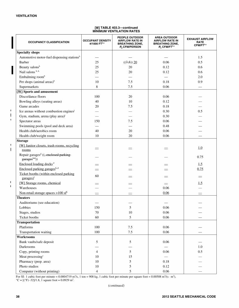
[W] TABLE 403.3—continuedMINIMUM VENTILATION RATES
For SI: 1 cubic foot per minute = 0.0004719 m3/s, 1 ton = 908 kg, 1 cubic foot per minute per square foot = 0.00508 m3/(s · m2), °C = [(°F) -32]/1.8, 1 square foot = 0.0929 m2.
(continued)
OCCUPANCY CLASSIFICATION OCCUPANT DENSITY#/1000 FT2 a
PEOPLE OUTDOOR AIRFLOW RATE IN BREATHING ZONE,
Rp CFM/PERSON
AREA OUTDOOR AIRFLOW RATE IN BREATHING ZONE,
Ra CFM/FT2 a
EXHAUST AIRFLOW RATE
CFM/FT2 a
Specialty shops
Automotive motor-fuel dispensing stationsb — — — 1.5
Barber 25 ((7.5)) 20 0.06 0.5
Beauty salonsb 25 20 0.12 0.6
Nail salons b, h 25 20 0.12 0.6
Embalming roomb — — — 2.0
Pet shops (animal areas)b 10 7.5 0.18 0.9
Supermarkets 8 7.5 0.06 —
[W] Sports and amusement
Disco/dance floors 100 20 0.06 —
Bowling alleys (seating areas) 40 10 0.12 —
Game arcades 20 7.5 0.18 —
Ice arenas without combustion enginesj — — 0.30 0.5
Gym, stadium, arena (play area)j — — 0.30 —
Spectator areas 150 7.5 0.06 —
Swimming pools (pool and deck area) — — 0.48 —
Health club/aerobics room 40 20 0.06 —
Health club/weight room 10 20 0.06 —
Storage
[W] Janitor closets, trash rooms, recycling rooms
— — — 1.0
Repair garagesd ((, enclosed parking garagesb,d))
— — — 0.75
Enclosed loading docks d — — — 1.5
Enclosed parking garagesb, d — — — 0.75
Ticket booths (within enclosed parking garages)l
60 — — —
[W] Storage rooms, chemical — — — 1.5
Warehouses — — 0.06 —
Non-retail storage spaces >100 sfk — — 0.06 —
Theaters
Auditoriums (see education) — — — —
Lobbies 150 5 0.06 —
Stages, studios 70 10 0.06 —
Ticket booths 60 5 0.06 —
Transportation
Platforms 100 7.5 0.06 —
Transportation waiting 100 7.5 0.06 —
Workrooms
Bank vaults/safe deposit 5 5 0.06 —
Darkrooms — — — 1.0
Copy, printing rooms 4 5 0.06 0.5
Meat processingc 10 15 — —
Pharmacy (prep. area) 10 5 0.18 —
Photo studios 10 5 0.12 —
Computer (without printing) 4 5 0.06 —
04_Seattle_Mech_2012.fm Page 38 Wednesday, November 13, 2013 1:25 PM

VENTILATION
2012 SEATTLE MECHANICAL CODE 39
403.3.1.3 Zone outdoor airflow. The zone outdoor air-flow rate (Voz), shall be determined in accordance withEquation 4-2.
(Equation 4-2)
403.3.2 System outdoor airflow. The outdoor air requiredto be supplied by each ventilation system shall be deter-mined in accordance with Sections 403.3.2.1 through403.3.2.3 as a function of system type and zone outdoorairflow rates.
403.3.2.1 Single zone systems. Where one air handlersupplies a mixture of outdoor air and recirculated returnair to only one zone, the system outdoor air intake flowrate (Vot) shall be determined in accordance with Equa-tion 4-3.
(Equation 4-3)
403.3.2.2 100-percent outdoor air systems. Whereone air handler supplies only outdoor air to one or morezones, the system outdoor air intake flow rate (Vot) shallbe determined using Equation 4-4.
(Equation 4-4)
403.3.2.3 Multiple zone recirculating systems. Whereone air handler supplies a mixture of outdoor air andrecirculated return air to more than one zone, the sys-tem outdoor air intake flow rate (Vot) shall be deter-mined in accordance with Sections 403.3.2.3.1 through403.3.2.3.4.
403.3.2.3.1 Primary outdoor air fraction. The pri-mary outdoor air fraction (Zp) shall be determinedfor each zone in accordance with Equation 4-5.
(Equation 4-5)
where:
Vpz = Primary airflow: The airflow rate suppliedto the zone from the air-handling unit at whichthe outdoor air intake is located. It includes out-door intake air and recirculated air from that air-handling unit but does not include air transferredor air recirculated to the zone by other means.For design purposes, Vpz shall be the zone designprimary airflow rate, except for zones with vari-able air volume supply and Vpz shall be the low-est expected primary airflow rate to the zonewhen it is fully occupied.
403.3.2.3.2 System ventilation efficiency. The sys-tem ventilation efficiency (Ev) shall be determinedusing Table 403.3.2.3.2 or Appendix A of ASHRAE62.1.
TABLE 403.3.2.3.2SYSTEM VENTILATION EFFICIENCYa,b
a. Max (Zp) is the largest value of Zp calculated using Equation 4-5 among allthe zones served by the system.
b. Interpolating between table values shall be permitted.
403.3.2.3.3 Uncorrected outdoor air intake. Theuncorrected outdoor air intake flow rate (Vou) shallbe determined in accordance with Equation 4-6.
(Equation 4-6)
VozVbzEz-------=
Vot Voz=
Vot Σall zonesVoz=
ZpVozVpz-------=
Max (Zp) Ev
≤ 0.15 1
≤ 0.25 0.9
≤ 0.35 0.8
≤ 0.45 0.7
≤ 0.55 0.6
≤ 0.65 0.5
≤ 0.75 0.4
> 0.75 0.3
Vou DΣall zonesRpPz Σall zonesRaAz+=
Notes to [W] TABLE 403.3 MINIMUM VENTILATION RATESa. Based upon net occupiable floor area. b. Mechanical exhaust required and the recirculation of air from such spaces is prohibited (see Section 403.2.1, Item 3). c. Spaces unheated or maintained below 50°F are not covered by these requirements unless the occupancy is continuous. d. Ventilation systems ((in enclosed parking garages)) shall comply with Section 404. e. Rates are per water closet or urinal. The higher rate shall be provided where the exhaust system is designed to operate intermittently. The lower rate shall be
permitted only where the exhaust system is designed to operate continuously while occupied.f. Rates are per room unless otherwise indicated. The higher rate shall be provided where the exhaust system is designed to operate intermittently. The lower rate
shall be permitted only where the exhaust system is designed to operate continuously while occupied. [W] g.Mechanical exhaust is required and recirculation is prohibited ((except that recirculation shall be permitted where the resulting supply airstream consists of
not more than 10 percent air recirculated from these spaces (see Section 403.2.1, Items 2 and 4).)) h. For nail salons, each nail station shall be provided with a source capture system capable of exhausting not less than 50 cfm per station.[W] i.A laundry area within a kitchen or bathroom is not required to have local exhaust. For the laundry area to qualify as being within the kitchen, the laundry
room door must open directly into the kitchen and not into an adjacent corridor. Where there are doors that separate the laundry area from the kitchen orbathroom the door shall be louvered.
[W] j.When combustion equipment is intended to be used on the playing surface, additional dilution ventilation and/or source control shall be provided.k. Transfer air permitted in accordance with Section 403.2.2. For non-retail storage areas, transfer air is also permitted from an adjacent open parking garage, or
an enclosed parking garage or loading dock that is mechanically ventilated in accordance with Section 404.l. This space shall be maintained at a positive pressure. See Section 404.3.
04_Seattle_Mech_2012.fm Page 39 Wednesday, November 13, 2013 1:25 PM

VENTILATION
40 2012 SEATTLE MECHANICAL CODE
where:
D = Occupant diversity: the ratio of the systempopulation to the sum of the zone populations,determined in accordance with Equation 4-7.
(Equation 4-7)
where:
Ps = System population: The total number ofoccupants in the area served by the system. Fordesign purposes, Ps shall be the maximum num-ber of occupants expected to be concurrently inall zones served by the system.
403.3.2.3.4 Outdoor air intake flow rate. The out-door air intake flow rate (Vot) shall be determined inaccordance with Equation 4-8.
(Equation 4-8)
403.4 Exhaust ventilation. Exhaust airflow rate shall be pro-vided in accordance with the requirements in Table 403.3.Exhaust makeup air shall be permitted to be any combinationof outdoor air, recirculated air and transfer air, except as lim-ited in accordance with Section 403.2.
403.5 System operation. The minimum flow rate of outdoorair that the ventilation system must be capable of supplyingduring its operation shall be permitted to be based on the rateper person indicated in Table 403.3 and the actual number ofoccupants present.
403.6 Variable air volume system control. Variable air vol-ume air distribution systems, other than those designed tosupply only 100-percent outdoor air, shall be provided withcontrols to regulate the flow of outdoor air. Such control sys-tem shall be designed to maintain the flow rate of outdoor airat a rate of not less than that required by Section 403.3 overthe entire range of supply air operating rates. Calculationsand a description of controls operation shall be submittedwith the permit drawings.
403.7 Balancing. The ventilation air distribution systemshall be provided with means to adjust the system to achieveat least the minimum ventilation airflow rate as required bySections 403.3 and 403.4. Ventilation systems shall be bal-anced by an approved method. Such balancing shall verifythat the ventilation system is capable of supplying andexhausting the airflow rates required by Sections 403.3 and403.4.
[W] 403.8 Ventilation systems for Group R occupancies.Each dwelling unit or sleeping unit shall be equipped withlocal exhaust and whole house ventilation systems and shallcomply with Sections 403.8.1 through 403.8.10. All occupan-cies other than Group R occupied spaces that support theGroup R occupancy shall meet the ventilation requirementsof Section 402 or Sections 403.1 to 403.7.
403.8.1 Minimum ventilation performance. Ventilationsystems shall be designed and installed to satisfy the venti-lation requirements of Table 403.3 or Table 403.8.1.
Breathing zone ventilation rates from Table 403.3 shall becalculated per Section 403.3.1.1 and corrected per zone airdistribution effectiveness requirements per Section403.3.1.2.
TABLE 403.8.1VENTILATION RATES FOR ALL GROUP R PRIVATE
DWELLINGS, SINGLE AND MULTIPLE(Continuously Operating Systems)
1. Ventilation rates in table are minimum outdoor airflow rates measured incfm.
403.8.2 Control and operation. Controls for and opera-tion of ventilation systems shall comply with this section.
Exception: Engineered central ventilation systemsserving dwelling units or sleeping units are not requiredto have individual controls for each dwelling unit orsleeping unit when designed for continuous operationand approved by the code official.
1. Location of controls. Controls for all ventilation sys-tems shall be readily accessible by the occupant.
2. Instructions. Operating instructions for whole houseventilation systems shall be provided to the occu-pant by the installer of the system.
3. Local exhaust ventilation systems. Local exhaustventilation systems shall be controlled by manualswitches, dehumidistats, timers, or other approvedmeans.
4. Continuous whole house ventilation systems. Con-tinuous whole house ventilation systems shall oper-ate continuously. Exhaust fans, forced-air systemfans, or supply fans shall be equipped with “fan on”as override controls. Controls shall be capable ofoperating the ventilation system without energizingother energy-consuming appliances. A label shall beaffixed to the controls that reads “Whole HouseVentilation (see operating instructions).”
5. Intermittent whole house ventilation systems. Inter-mittent whole house ventilation systems shall com-ply with the following:
5.1. They shall be capable of operating intermit-tently and continuously.
5.2. They shall have controls capable of operatingthe exhaust fans, forced-air system fans, or sup-ply fans without energizing other energy-con-suming appliances.
5.3. The ventilation rate shall be adjusted accordingto the exception in Section 403.8.5.1.
DPs
Σall zonesPz------------------------=
VotVouEv--------=
FLOORAREA (ft2)
BEDROOMS1
0-1 2-3 4-5 6-7 > 7
< 1500 30 45 60 75 90
1501 - 3000 45 60 75 90 105
3001 - 4500 60 75 90 105 120
4501 - 6000 75 90 105 120 135
6001 - 7500 90 105 120 135 150
> 7500 105 120 135 150 165
04_Seattle_Mech_2012.fm Page 40 Wednesday, November 13, 2013 1:25 PM

VENTILATION
2012 SEATTLE MECHANICAL CODE 41
5.4. The system shall be designed so that it can oper-ate automatically based on the type of controltimer installed.
5.5. The intermittent mechanical ventilation systemshall operate at least one hour out of every four.
5.6. The system shall have a manual control andautomatic control, such as a 24-hour clocktimer.
5.7. At the time of final inspection, the automaticcontrol shall be set to operate the whole housefan according to the schedule used to calculatethe whole house fan sizing.
5.8. A label shall be affixed to the control that reads“Whole House Ventilation (see operatinginstructions).”
403.8.3 Outdoor air intake locations. Outdoor airintakes shall be classified as either operable openings ormechanical air intakes. The intake locations for operableopenings and mechanical air intakes shall comply with thefollowing:
1. Openings for mechanical air intakes shall complywith Section 401.4. Operable openings shall complywith Section 401.4, Items 2, 4 and 5 only.
2. Intake openings shall not be located closer than 10feet from an appliance vent outlet unless such ventoutlet is 3 feet above the outdoor air inlet. The ventshall be permitted to be closer if specifically allowedby Chapter 8 or by the International Fuel Gas Code.
3. Intake openings shall be located where they will notpick up objectionable odors, fumes, or flammablevapors.
4. Intake openings shall be located where they will nottake air from a hazardous or unsanitary location.
5. Intake openings shall be located where they will nottake air from a room or space having a fuel-burningappliance.
6. Intake openings shall not be located closer than 10feet from a vent opening of a plumbing drainagesystem unless the vent opening is at least 3 feetabove the air inlet.
7. Intake openings shall not be located where they willtake air from an attic, crawl space, or garage.
403.8.4 Local exhaust ventilation requirements. Localexhaust ventilation systems shall exhaust at least the vol-ume of air required for exhaust in Table 403.3. Exhaustshall be provided in each kitchen, bathroom, water closet,laundry area, indoor swimming pool, spa, and other roomswhere water vapor or cooking odor is produced. Localexhaust ventilation ducts shall terminate outdoors.
403.8.4.1 Local exhaust systems. Exhaust systemsshall be designed and installed to meet all of the criteriabelow:
1. Local exhaust shall be discharged outdoors.
2. Exhaust outlets shall comply with Section 501.3.
3. Pressure equalization shall comply with Section501.4.
4. Exhaust ducts in systems which are designed tooperate intermittently shall be equipped withbackdraft dampers.
5. All exhaust ducts in unconditioned spaces shallbe insulated to a minimum of R-4.
6. Terminal outlet elements shall have at least theequivalent net free area of the ductwork.
7. Terminal outlet elements shall be screened orotherwise protected as required by Section501.3.2.
8. Exhaust fans in separate dwelling units or sleep-ing units shall not share common exhaust ductsunless the system is engineered for this opera-tion.
9. Where permitted by Chapter 5, multiple localexhaust ducts may be combined. If more than oneof the exhaust fans in a dwelling unit or sleepingunit shares a common exhaust duct then eachexhaust fan shall be equipped with a backdraftdamper to prevent the recirculation of exhaust airfrom one room to another room via the exhaustducting system.
403.8.4.2 Local exhaust fans. Exhaust fan construc-tion and sizing shall meet the following criteria.
1. Exhaust fans shall be tested and rated in accor-dance with the airflow and sound rating proce-dures of the Home Ventilating Institute: HVI 915Loudness Testing and Rating Procedure; HVI916 Airflow Test Procedure; and HVI 920 Prod-uct Performance Certification Procedure.
Exception: Range hoods and down-draftexhaust fans used for local exhaust for kitch-ens are not required to be rated.
2. Fan airflow rating and duct systems shall bedesigned and installed to deliver at least theexhaust airflow required by Table 403.3. The air-flows required refer to the delivered airflow ofthe system as installed and tested using a flowhood, flow grid, or other airflow measurementdevice.
Exceptions:
1. An exhaust airflow rating at a pressureof 0.25 in. w.g. may be used, providedthe duct sizing meets the prescriptiverequirements of Table 403.8.4.2.
2. Where a range hood or down-draftexhaust fan is used to satisfy the localexhaust requirements for kitchens, therange hood or down draft exhaust shallnot be less than 100 cfm at 0.10 in. w.g.
04_Seattle_Mech_2012.fm Page 41 Wednesday, November 13, 2013 1:25 PM

VENTILATION
42 2012 SEATTLE MECHANICAL CODE
403.8.5 Whole house ventilation requirements. Allwhole house ventilation systems shall comply with Sec-tions 403.8.5.1 and 403.8.5.2. Each dwelling unit or sleep-ing unit shall be equipped with one of the following fourtypes of mechanical whole house ventilation systems:
1. A system using exhaust fans (see Section 403.8.6);
2. A system integrated with forced-air systems (seeSection 403.8.7);
3. A system using supply fans (see Section 403.8.8); or
4. A heat or energy recovery ventilation system (seeSection 403.8.9).
The whole house exhaust system is permitted to be oneof the local exhaust systems required by Section 403.8.4 aslong as the requirements of this section, in addition to therequirements of Section 403.8.4, are met.
403.8.5.1 Outdoor air. Outdoor air shall be distributedto each habitable space. Where outdoor air supplyintakes are separated from exhaust vents by doors,means shall be provided to ensure airflow to all sepa-rated habitable spaces by installing distribution ducts,installed grilles, transoms, doors undercut to a mini-mum of 1/2-inch above the surface of the finish floorcovering, or other similar means where permitted bythe International Building Code.
The mechanical system shall operate continuously tosupply at least the volume of outdoor air required inTable 403.3 or Table 403.8.1.
Exception: Intermittently operating ventilation sys-tems: The whole house mechanical ventilation sys-tem is permitted to operate intermittently where thesystem has controls that enable operation for not lessthan 25 percent of each 4-hour segment and the ven-tilation rate prescribed in Table 403.3 or Table403.8.1 is multiplied by the factor determined inaccordance with Table 403.8.5.1.
The intermittent mechanical ventilation system shalloperate at least one hour out of every four. A minimumof six cycles are required per day.
TABLE 403.8.5.1INTERMITTENT WHOLE HOUSE MECHANICAL
VENTILATION RATE FACTORSa, b
a. For ventilation system run-time values between those given, the factorsare permitted to be determined by interpolation.
b. Extrapolation beyond the table is prohibited.
Run-Time Percentage in Each 4-Hour Segment 25% 33% 50% 66% 75% 100%
Ventilation Rate Factor (Fv)
a 4 3 2 1.5 1.3 1.0
TABLE 403.8.4.2PRESCRIPTIVE EXHAUST DUCT SIZING
1. For each additional elbow, subtract 10 feet from length.2. Flex ducts of this diameter are not permitted with fans of this size.
FAN TESTED CFM AT 0.25 INCHES W.G.
MINIMUM FLEX DIAMETER
MAXIMUMLENGTH IN FEET
MINIMUMSMOOTH DIAMETER
MAXIMUMLENGTH IN FEET
MAXIMUMELBOWS1
50 4 inches 25 4 inches 70 3
50 5 inches 90 5 inches 100 3
50 6 inches No Limit 6 inches No Limit 3
80 4 inches2 NA 4 inches 20 3
80 5 inches 15 5 inches 100 3
80 6 inches 90 6 inches No Limit 3
100 5 inches2 NA 5 inches 50 3
100 6 inches 45 6 inches No Limit 3
125 6 inches 15 6 inches No Limit 3
125 7 inches 70 7 inches No Limit 3
04_Seattle_Mech_2012.fm Page 42 Friday, November 22, 2013 10:34 AM
VENTILATION
2012 SEATTLE MECHANICAL CODE 43
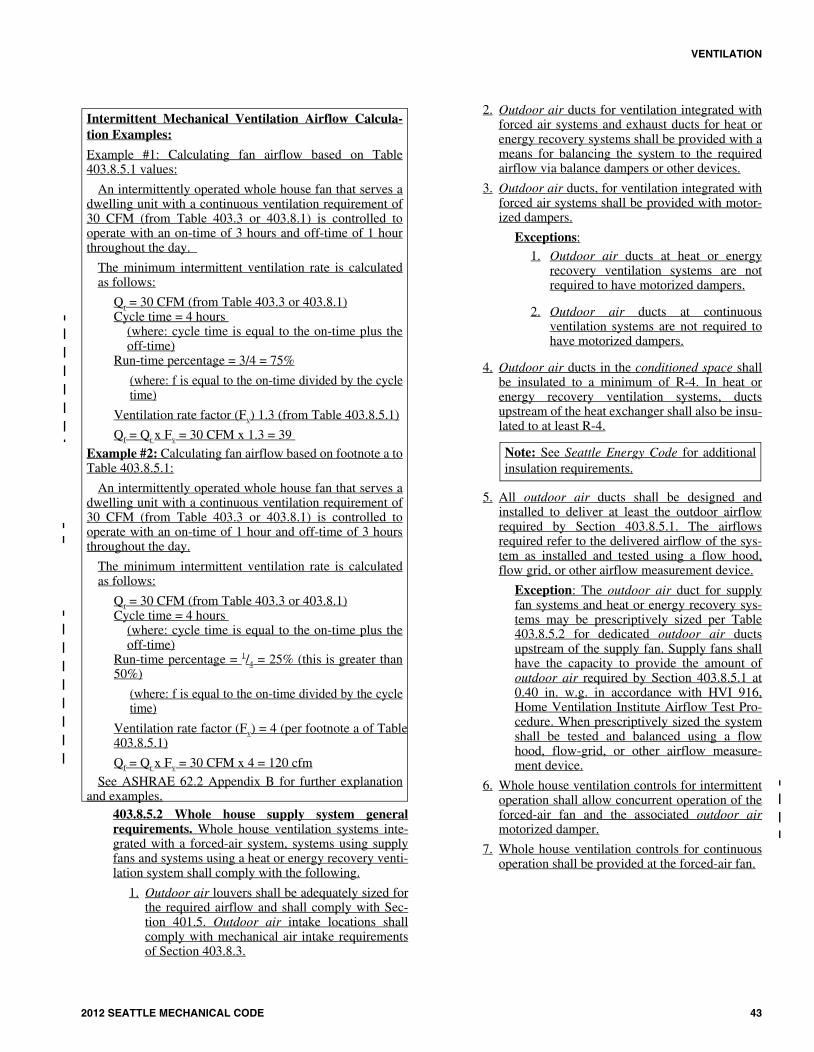
403.8.5.2 Whole house supply system generalrequirements. Whole house ventilation systems inte-grated with a forced-air system, systems using supplyfans and systems using a heat or energy recovery venti-lation system shall comply with the following.
1. Outdoor air louvers shall be adequately sized forthe required airflow and shall comply with Sec-tion 401.5. Outdoor air intake locations shallcomply with mechanical air intake requirementsof Section 403.8.3.
2. Outdoor air ducts for ventilation integrated withforced air systems and exhaust ducts for heat orenergy recovery systems shall be provided with ameans for balancing the system to the requiredairflow via balance dampers or other devices.
3. Outdoor air ducts, for ventilation integrated withforced air systems shall be provided with motor-ized dampers.
Exceptions:
1. Outdoor air ducts at heat or energyrecovery ventilation systems are notrequired to have motorized dampers.
2. Outdoor air ducts at continuousventilation systems are not required tohave motorized dampers.
4. Outdoor air ducts in the conditioned space shallbe insulated to a minimum of R-4. In heat orenergy recovery ventilation systems, ductsupstream of the heat exchanger shall also be insu-lated to at least R-4.
5. All outdoor air ducts shall be designed andinstalled to deliver at least the outdoor airflowrequired by Section 403.8.5.1. The airflowsrequired refer to the delivered airflow of the sys-tem as installed and tested using a flow hood,flow grid, or other airflow measurement device.
Exception: The outdoor air duct for supplyfan systems and heat or energy recovery sys-tems may be prescriptively sized per Table403.8.5.2 for dedicated outdoor air ductsupstream of the supply fan. Supply fans shallhave the capacity to provide the amount ofoutdoor air required by Section 403.8.5.1 at0.40 in. w.g. in accordance with HVI 916,Home Ventilation Institute Airflow Test Pro-cedure. When prescriptively sized the systemshall be tested and balanced using a flowhood, flow-grid, or other airflow measure-ment device.
6. Whole house ventilation controls for intermittentoperation shall allow concurrent operation of theforced-air fan and the associated outdoor airmotorized damper.
7. Whole house ventilation controls for continuousoperation shall be provided at the forced-air fan.
Intermittent Mechanical Ventilation Airflow Calcula-tion Examples:
Example #1: Calculating fan airflow based on Table403.8.5.1 values:
An intermittently operated whole house fan that serves adwelling unit with a continuous ventilation requirement of30 CFM (from Table 403.3 or 403.8.1) is controlled tooperate with an on-time of 3 hours and off-time of 1 hourthroughout the day.
The minimum intermittent ventilation rate is calculatedas follows:
Qr = 30 CFM (from Table 403.3 or 403.8.1)Cycle time = 4 hours
(where: cycle time is equal to the on-time plus theoff-time)
Run-time percentage = 3/4 = 75%
(where: f is equal to the on-time divided by the cycletime)
Ventilation rate factor (Fv) 1.3 (from Table 403.8.5.1)
Qf = Qr x Fv = 30 CFM x 1.3 = 39
Example #2: Calculating fan airflow based on footnote a toTable 403.8.5.1:
An intermittently operated whole house fan that serves adwelling unit with a continuous ventilation requirement of30 CFM (from Table 403.3 or 403.8.1) is controlled tooperate with an on-time of 1 hour and off-time of 3 hoursthroughout the day.
The minimum intermittent ventilation rate is calculatedas follows:
Qr = 30 CFM (from Table 403.3 or 403.8.1)Cycle time = 4 hours
(where: cycle time is equal to the on-time plus theoff-time)
Run-time percentage = 1/4 = 25% (this is greater than50%)
(where: f is equal to the on-time divided by the cycletime)
Ventilation rate factor (Fv) = 4 (per footnote a of Table403.8.5.1)
Qf = Qr x Fv = 30 CFM x 4 = 120 cfm
See ASHRAE 62.2 Appendix B for further explanationand examples.
Note: See Seattle Energy Code for additionalinsulation requirements.
04_Seattle_Mech_2012.fm Page 43 Wednesday, November 13, 2013 1:25 PM

VENTILATION
44 2012 SEATTLE MECHANICAL CODE
TABLE 403.8.5.2PRESCRIPTIVE SUPPLY FAN DUCT SIZING
403.8.6 Whole house ventilation with exhaust fan sys-tems. This section establishes minimum requirements formechanical whole house ventilation systems using exhaustfans.
403.8.6.1 Outdoor air. Exhaust fan only ventilationsystems shall provide outdoor air to each occupiablespace through one of the following methods:
1. Outdoor air may be drawn through air inletsinstalled in exterior walls or windows.
The air inlets shall comply with all of the fol-lowing:
1.1. Inlets shall have controllable, secureopenings and shall be designed to notcompromise the thermal properties ofthe building envelope.
1.2. Inlets shall be readily accessible tooccupants, including compliance withSection 1109.13 of the InternationalBuilding Code for designatedAccessible units, Type A units andType B units.
1.3. Inlets shall be screened or otherwiseprotected from entry by insects, leaves,or other material.
1.4. Inlets shall provide not less than 4square inches of net free area ofopening for each 10 cfm of outdoor airrequired in Table 403.3 or Table403.8.1.
1.5. Any inlet or combination of inletswhich provide 10 cfm at 10 pascals asin accordance with HVI 916 HomeVentilation Institute Air Flow TestProcedure, and HVI 920 HomeVentilation Institute ProductPerformance Certification Procedureare deemed equivalent to 4 squareinches of net free area.
1.6. Each occupiable space shall have aminimum of one air inlet that has aminimum of 4 square inches of net freearea.
2. In high-rise buildings, outdoor air may be drawnin through operable windows, doors, louvers orother operable openings to the outdoors. Exteriorspaces shall have a minimum openable area of 4percent of the total floor area being ventilated.Doors exiting to a corridor, court or public wayshall not be used to provide outdoor air.
The operable openings shall comply with thefollowing:
2.1. Openings shall be controllable,securable, and shall be designed to notcompromise the thermal properties ofthe building envelope.
2.2. Openings shall be readily accessible tooccupants, including compliance withSection 1109.13 of the InternationalBuilding Code for designatedAccessible units, Type A units andType B units.
3. For interior adjoining spaces without outdoor airopenings, one of the following two options shallbe used to ventilate the interior adjoining space:
3.1. Provide a whole house transfer fan atthe interior adjoining space sized toprovide a minimum of the ventilationrate required per Section 403.8.5.1.The transfer fan shall circulate airbetween the interior room or space andthe adjacent habitable space. Thetransfer fan may operate continuouslyor intermittently using controls perSection 403.8.2.
3.2. Provide a permanent opening to theinterior adjoining space. Opening shallbe unobstructed and shall have an areaof not less than 8 percent of the floorarea of the interior adjoining space, butnot less than 25 square feet.
403.8.6.2 Outside air intake locations. All outside airintake opening types described in Section 403.8.6.1shall be classified as operable openings and shall not beclassified as mechanical air intakes. The intake loca-tions shall comply with Section 403.8.3.
403.8.6.3 Whole house exhaust system. Whole houseexhaust system shall be designed and installed to meetall of the applicable criteria below:
1. Whole house ventilation exhaust shall be dis-charged outdoors.
2. Exhaust outlets shall comply with Section501.3.2.
3. Exhaust ducts in systems which are designed tooperate intermittently shall be equipped withbackdraft dampers.
SUPPLY FAN TESTED CFM AT 0.40" w.g.
Specified Volumefrom Table 408.1
Minimum SmoothDuct Diameter
Minimum FlexibleDuct Diameter
50 - 90 cfm 4 inch 5 inch
90 - 150 cfm 5 inch 6 inch
150 - 250 cfm 6 inch 7 inch
250 – 400 cfm 7 inch 8 inch
ñ
ñ
04_Seattle_Mech_2012.fm Page 44 Wednesday, November 13, 2013 1:25 PM

VENTILATION
2012 SEATTLE MECHANICAL CODE 45
4. All exhaust ducts in unconditioned spaces shallbe insulated to a minimum of R-4.5. Terminaloutlet elements shall have at least the equivalentnet free area of the ductwork.
5. Terminal outlet elements shall be screened orotherwise protected as required by Section501.3.2.
6. One of the required local exhaust fans for thelaundry room or bathroom may be designated asthe whole house exhaust fan.
7. Exhaust fans in separate dwelling units or sleep-ing units shall not share common exhaust ductsunless the system is engineered for this operation.
8. Where permitted by Chapter 5, whole houseexhaust ducts may be combined with other localexhaust ducts. If more than one of the exhaustfans in a dwelling unit or sleeping unit shares acommon exhaust duct then each exhaust fan shallbe equipped with a backdraft damper to preventthe recirculation of exhaust air from one room toanother room via the exhaust ducting system.
403.8.6.4 Whole house exhaust and transfer fans.Exhaust fan construction and sizing shall meet the fol-lowing criteria.
1. Exhaust and transfer fans shall be tested and ratedin accordance with the airflow and sound ratingprocedures of the HVI 915 Loudness Testing andRating Procedure; HVI 916 Airflow Test Proce-dure, and HVI 920 Product Performance Certifi-cation Procedure.
2. Installation of system or equipment shall be car-ried out in accordance with manufacturer’sdesign requirements and installation instructions.
3. Fan airflow rating and duct system shall bedesigned and installed to deliver at least the out-door airflow required by Table 403.3 or Table403.8.1. The airflows required refer to the deliv-ered airflow of the system as installed and testedusing a flow hood, flow grid, or other airflowmeasurement device.
Exception: An airflow rating at a pressure of0.25 in. w.g. may be used, provided the ductsizing meets the prescriptive requirements ofTable 403.8.5.2.
403.8.6.5 Fan noise. Whole house exhaust and transferfans located 4 feet or less from the interior grille shallhave a sone rating of 1.0 or less measured at 0.10 incheswater gauge. Manufacturer's noise ratings shall be deter-mined in accordance with HVI 915 Loudness Testingand Rating Procedure. Remotely mounted fans shall beacoustically isolated from the structural elements of thebuilding and from attached ductwork using insulatedflexible duct or other approved material.
403.8.7 Whole house ventilation integrated with forced-air systems. This section establishes minimum require-ments for mechanical whole house ventilation systemsusing forced-air system fans.
403.8.7.1 Outdoor air. Forced-air system fan ventila-tion systems shall provide outdoor air through one ofthe following methods:
1. A dedicated outdoor air louver and outdoor airduct for each dwelling unit or sleeping unit shallsupply outdoor air to the return side of theforced-air system fan; or
2. A central outdoor air delivery system that sup-plies multiple dwelling units or sleeping unitsshall supply outdoor air to the return side of theforced air system fan.
403.8.7.2 Whole house forced-air system. Where out-door air is provided to each habitable dwelling unit orsleeping unit by a forced air system, the outdoor airduct shall be connected to the return air stream at apoint within 4 feet upstream of the forced-air unit. Itshall not be connected directly to the forced-air unitcabinet in order to prevent thermal shock to the heatexchanger. At a minimum, filtration of the outdoor airshall be provided at the forced-air unit. The filter shallbe accessible for regular maintenance and replacement.The filter shall have a Minimum Efficiency RatingValue (MERV) of at least 6.
403.8.8 Whole house ventilation with supply fan sys-tems. This section establishes minimum requirements formechanical whole house ventilation systems using supplyfan systems.
403.8.8.1 Outdoor air. Supply fan ventilation systemsshall provide outdoor air through one of the followingmethods:
1. A dedicated outdoor air louver and outdoor airduct for each dwelling unit or sleeping unit shallsupply outdoor air to a supply fan; or
2. A central outdoor air supply fan system shall dis-tribute unconditioned or conditioned air to multi-ple dwelling units or sleeping units.
403.8.8.2 Whole house supply system. Where outdoorair is provided to each habitable dwelling unit or sleep-ing unit by supply fan systems the outdoor air shall befiltered.
The system filter may be located at the intake deviceor in line with the fan. The filter shall be accessible forregular maintenance and replacement. The filter shallhave a Minimum Efficiency Rating Value (MERV) ofat least 6.
403.8.9 Whole house ventilation with heat recovery orenergy recovery ventilation systems. This section estab-lishes minimum requirements for mechanical whole houseventilation systems using heat recovery or energy recoveryventilation systems.
04_Seattle_Mech_2012.fm Page 45 Wednesday, November 13, 2013 1:25 PM

VENTILATION
46 2012 SEATTLE MECHANICAL CODE
403.8.9.1 Outdoor air. Heat recovery or energy recov-ery ventilation systems shall provide outdoor airthrough one of the following methods:
1. A dedicated outdoor air louver and outdoor airduct for each dwelling unit or sleeping unit shallsupply outdoor air to the heat recovery or energyrecovery ventilator; or
2. A central outdoor air heat recovery or energyrecovery unit shall distribute conditioned air tomultiple dwelling units or sleeping units.
403.8.9.2 Whole house heat recovery ventilator sys-tem. Where outdoor air is provided to each habitabledwelling unit or sleeping unit by heat recovery orenergy recovery ventilator the outdoor air shall be fil-tered. The filter shall be located on the upstream side ofthe heat exchanger in both the intake and exhaust air-streams with a Minimum Efficiency Rating Value(MERV) of at least 6. The system filter may be locatedat the intake device or in line with the fan. The filtershall be accessible for regular maintenance and replace-ment.
403.8.10 Local exhaust ventilation and whole houseventilation alternate performance or design require-ments. In lieu of complying with Sections 403.8.4 or403.8.5, compliance with the section shall be demon-strated through engineering calculations by an engineerlicensed to practice in the state of Washington or by per-formance testing. Documentation of calculations or per-formance test results shall be submitted to and approvedby the code official. Performance testing shall be con-ducted in accordance with approved test methods.
403.8.11 Alternate systems. When approved by the codeofficial, systems designed in accordance with ASHRAEStandard 62.2 shall be permitted.
403.9 Corridors. Air movement in corridors shall complywith Section 601 of this code and the International BuildingCode.
SECTION 404VENTILATION OF ENCLOSED
MOTOR VEHICLE OCCUPANCIES((ENCLOSED PARKING GARAGES))
404.1 Enclosed parking garage((s)), loading dock, andmotor vehicle repair garage exhaust ventilation systems.Mechanical ventilation systems for enclosed parking garages,loading docks, and motor vehicle repair garages shall ((bepermitted to)) operate intermittently in accordance with Item1, Item 2 or both.
1. The system shall be arranged to operate automaticallyupon detection of vehicle operation or the presence ofoccupants by approved automatic detection devices.
2. The system shall be arranged to operate automaticallyby means of carbon monoxide detectors applied in con-junction with nitrogen dioxide detectors that modulatethe ventilation system by staging fans or varying fanspeed to maintain gas concentrations below specified
maximum levels. Such detectors shall be designed forthe specific use and installed in accordance with theirmanufacturers’ recommendations. Mechanical ventila-tion systems and gas sensor systems controls shall com-ply with Section 1412.9 of the International EnergyConservation Code.
404.1.1 Ventilation makeup air. Ventilation makeup airshall be mechanically supplied to levels of enclosed load-ing docks and parking garages more than 3 stories aboveor below the nearest garage or loading dock entrance orexit.
404.1.2 Exhaust termination point. Exhaust terminationpoints shall comply with Section 501.3.1.1.
404.2 Minimum ventilation.
404.2.1 Enclosed parking garages and motor vehiclerepair garages. In enclosed parking garages and motorvehicle repair garages, ((A))automatic operation of thesystem shall not reduce the ventilation airflow rate below0.05 cfm per square foot (0.00025 m3/s • m2) of the floorarea and the ventilation system shall be capable of produc-ing a ventilation airflow rate of 0.75 cfm per square foot(0.0038 m3/s • m2) of floor area.
Exception: Ventilation systems located in areas withautomated parking systems where the engines of themotor vehicles are not operating shall provide a contin-uous ventilation airflow rate of 50 cfm per parkingstall. This exception does not apply to the vehicle dropoff area.
404.2.2 Enclosed loading docks. In enclosed loadingdocks, automatic operation of the system shall not reducethe ventilation airflow rate below 1.0 cfm per square foot(0.00507 m3/s • m2) of the floor area and the ventilationsystems shall be capable of producing a ventilation airflowrate of 1.5 cfm per square foot (0.0076 m3/s • m2) of floorarea.
404.3 Occupied spaces accessory to public garages andmotor vehicle repair garages. Connecting offices, waitingrooms, ticket booths, elevator lobbies and similar uses thatare accessory to a public garage or motor vehicle repairgarage shall be maintained at a positive pressure relative tothe garage and shall be provided with ventilation in accor-dance with Section 403.3.
404.4 Motor vehicle repair garages. In buildings used forthe repair of motor vehicles, each repair stall or stand shall beequipped with an exhaust capture system that connectsdirectly to the repair engine exhaust source and prevents theescape of fumes. The exhaust system shall exhaust to the out-door atmosphere. See Section 502.15 for additional require-ments. Ventilation shall be provided for the motor vehiclerepair garage in accordance with Section 404.
SECTION 405SYSTEMS CONTROL
405.1 General. Mechanical ventilation systems shall be pro-vided with manual or automatic controls that will operatesuch systems whenever the spaces are occupied. Air-condi-
ñ
04_Seattle_Mech_2012.fm Page 46 Friday, November 22, 2013 10:36 AM

VENTILATION
2012 SEATTLE MECHANICAL CODE 47
tioning systems that supply required ventilation air shall beprovided with controls designed to automatically maintainthe required outdoor air supply rate during occupancy. Addi-tional mechanical system control requirements are containedin the International Energy Conservation Code.
SECTION 406VENTILATION OF UNINHABITED SPACES
406.1 General. ((Uninhabited spaces, such as crawl)) Crawlspaces and attics((,)) shall be provided with natural ventila-tion openings as required by the International Building Codeor shall be provided with a mechanical exhaust and supply airsystem. The mechanical exhaust rate shall be not less than0.02 cfm per square foot (0.00001 m3/s • m2) of horizontalarea and shall be automatically controlled to operate when therelative humidity in the space served exceeds 60 percent.
04_Seattle_Mech_2012.fm Page 47 Wednesday, November 13, 2013 1:25 PM

48 2012 SEATTLE MECHANICAL CODE
04_Seattle_Mech_2012.fm Page 48 Wednesday, November 13, 2013 1:25 PM