Embed Size (px)
Citation preview
1-1
Section 1
v20170407a
SECTION 1 OVERVIEW
Conveyor Layouts
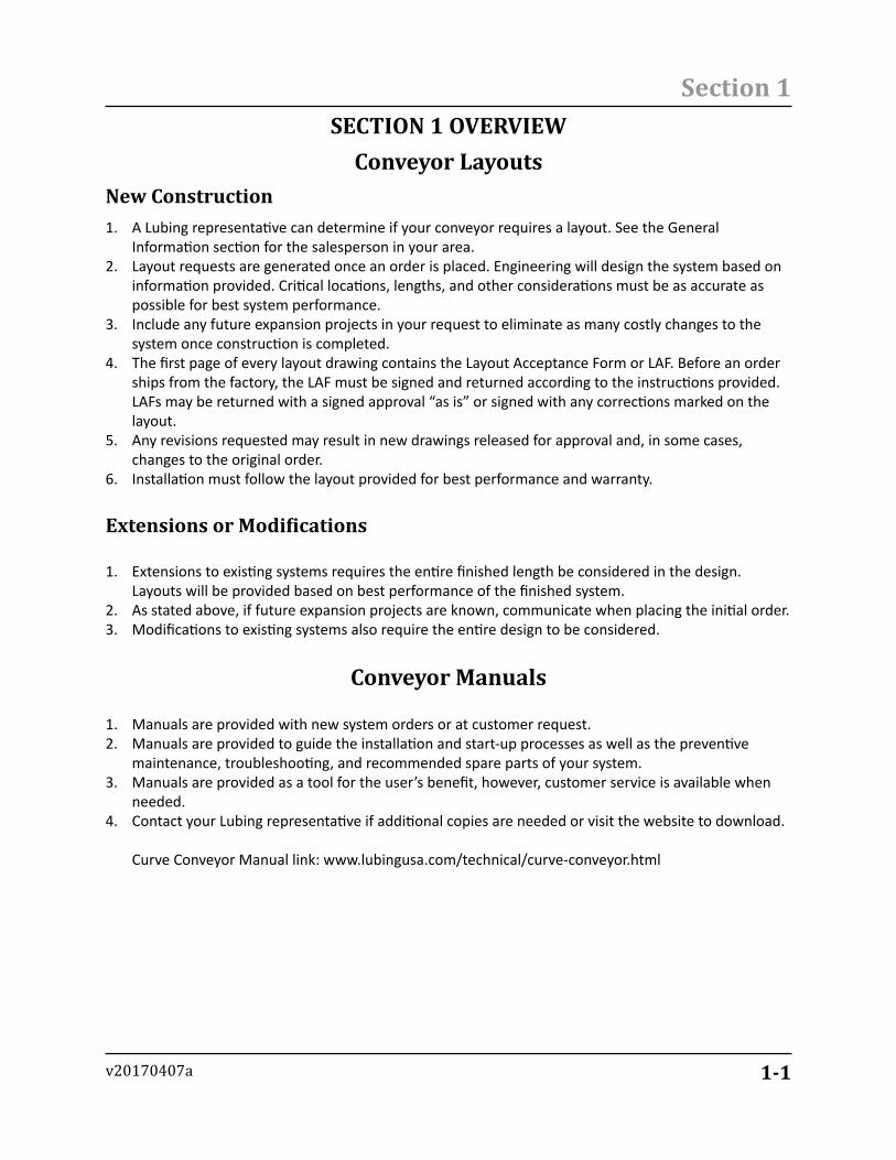
1. A Lubing representative can determine if your conveyor requires a layout. See the General Information section for the salesperson in your area.
2. Layout requests are generated once an order is placed. Engineering will design the system based on information provided. Critical locations, lengths, and other considerations must be as accurate as possible for best system performance.
3. Include any future expansion projects in your request to eliminate as many costly changes to the system once construction is completed.
4. The first page of every layout drawing contains the Layout Acceptance Form or LAF. Before an order ships from the factory, the LAF must be signed and returned according to the instructions provided. LAFs may be returned with a signed approval “as is” or signed with any corrections marked on the layout.
5. Any revisions requested may result in new drawings released for approval and, in some cases, changes to the original order.
6. Installation must follow the layout provided for best performance and warranty.
Extensions or Modifications
New Construction
1. Extensions to existing systems requires the entire finished length be considered in the design. Layouts will be provided based on best performance of the finished system.
2. As stated above, if future expansion projects are known, communicate when placing the initial order.3. Modifications to existing systems also require the entire design to be considered.
Conveyor Manuals
1. Manuals are provided with new system orders or at customer request.2. Manuals are provided to guide the installation and start-up processes as well as the preventive
maintenance, troubleshooting, and recommended spare parts of your system.3. Manuals are provided as a tool for the user’s benefit, however, customer service is available when
needed.4. Contact your Lubing representative if additional copies are needed or visit the website to download.
Curve Conveyor Manual link: www.lubingusa.com/technical/curve-conveyor.html
1-2
Section 1
v20170407a
Using this ManualComponent Details Section
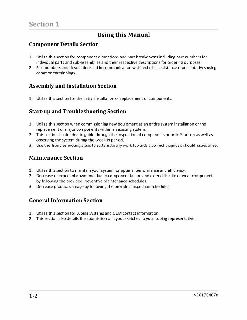
1. Utilize this section for component dimensions and part breakdowns including part numbers for individual parts and sub-assemblies and their respective descriptions for ordering purposes.
2. Part numbers and descriptions aid in communication with technical assistance representatives using common terminology.
Assembly and Installation Section
1. Utilize this section for the initial installation or replacement of components.
Start-up and Troubleshooting Section
1. Utilize this section when commissioning new equipment as an entire system installation or the replacement of major components within an existing system.
2. This section is intended to guide through the inspection of components prior to Start-up as well as observing the system during the Break-in period.
3. Use the Troubleshooting steps to systematically work towards a correct diagnosis should issues arise.
Maintenance Section
1. Utilize this section to maintain your system for optimal performance and efficiency.2. Decrease unexpected downtime due to component failure and extend the life of wear components
by following the provided Preventive Maintenance schedules.3. Decrease product damage by following the provided Inspection schedules.
General Information Section
1. Utilize this section for Lubing Systems and OEM contact information.2. This section also details the submission of layout sketches to your Lubing representative.
1-3
Section 1
v20170407a
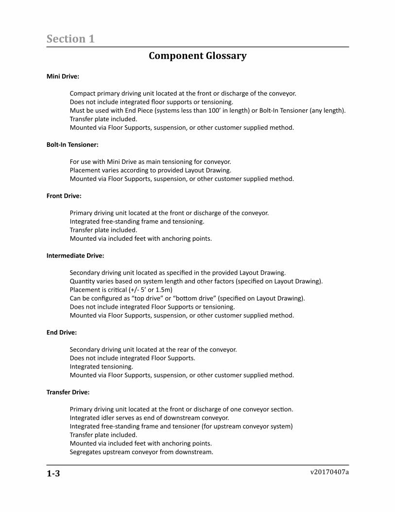
Component Glossary
Mini Drive:
Compact primary driving unit located at the front or discharge of the conveyor. Does not include integrated floor supports or tensioning. Must be used with End Piece (systems less than 100’ in length) or Bolt-In Tensioner (any length). Transfer plate included. Mounted via Floor Supports, suspension, or other customer supplied method.
Bolt-In Tensioner:
For use with Mini Drive as main tensioning for conveyor. Placement varies according to provided Layout Drawing. Mounted via Floor Supports, suspension, or other customer supplied method.
Front Drive:
Primary driving unit located at the front or discharge of the conveyor. Integrated free-standing frame and tensioning. Transfer plate included. Mounted via included feet with anchoring points.
Intermediate Drive:
Secondary driving unit located as specified in the provided Layout Drawing. Quantity varies based on system length and other factors (specified on Layout Drawing). Placement is critical (+/- 5’ or 1.5m) Can be configured as “top drive” or “bottom drive” (specified on Layout Drawing). Does not include integrated Floor Supports or tensioning. Mounted via Floor Supports, suspension, or other customer supplied method.
End Drive:
Secondary driving unit located at the rear of the conveyor. Does not include integrated Floor Supports. Integrated tensioning. Mounted via Floor Supports, suspension, or other customer supplied method.
Transfer Drive:
Primary driving unit located at the front or discharge of one conveyor section. Integrated idler serves as end of downstream conveyor. Integrated free-standing frame and tensioner (for upstream conveyor system) Transfer plate included. Mounted via included feet with anchoring points. Segregates upstream conveyor from downstream.
1-4
Section 1
v20170407a
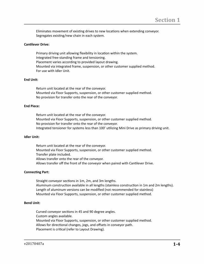
Eliminates movement of existing drives to new locations when extending conveyor. Segregates existing/new chain in each system.
Cantilever Drive:
Primary driving unit allowing flexibility in location within the system. Integrated free-standing frame and tensioning. Placement varies according to provided layout drawing. Mounted via integrated frame, suspension, or other customer supplied method. For use with Idler Unit.
End Unit:
Return unit located at the rear of the conveyor. Mounted via Floor Supports, suspension, or other customer supplied method. No provision for transfer onto the rear of the conveyor.
End Piece:
Return unit located at the rear of the conveyor. Mounted via Floor Supports, suspension, or other customer supplied method. No provision for transfer onto the rear of the conveyor. Integrated tensioner for systems less than 100’ utilizing Mini Drive as primary driving unit.
Idler Unit:
Return unit located at the rear of the conveyor. Mounted via Floor Supports, suspension, or other customer supplied method. Transfer plate included. Allows transfer onto the rear of the conveyor. Allows transfer off the front of the conveyor when paired with Cantilever Drive.
Connecting Part:
Straight conveyor sections in 1m, 2m, and 3m lengths. Aluminum construction available in all lengths (stainless construction in 1m and 2m lengths). Length of aluminum versions can be modified (not recommended for stainless) Mounted via Floor Supports, suspension, or other customer supplied method.
Bend Unit:
Curved conveyor sections in 45 and 90 degree angles. Custom angles available. Mounted via Floor Supports, suspension, or other customer supplied method. Allows for directional changes, jogs, and offsets in conveyor path. Placement is critical (refer to Layout Drawing).
1-5
Section 1
v20170407a
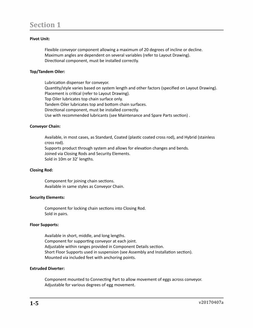
Pivot Unit:
Flexible conveyor component allowing a maximum of 20 degrees of incline or decline. Maximum angles are dependent on several variables (refer to Layout Drawing). Directional component, must be installed correctly.
Top/Tandem Oiler:
Lubrication dispenser for conveyor. Quantity/style varies based on system length and other factors (specified on Layout Drawing). Placement is critical (refer to Layout Drawing). Top Oiler lubricates top chain surface only. Tandem Oiler lubricates top and bottom chain surfaces. Directional component, must be installed correctly. Use with recommended lubricants (see Maintenance and Spare Parts section) .
Conveyor Chain:
Available, in most cases, as Standard, Coated (plastic coated cross rod), and Hybrid (stainless cross rod). Supports product through system and allows for elevation changes and bends. Joined via Closing Rods and Security Elements. Sold in 10m or 32’ lengths.
Closing Rod:
Component for joining chain sections. Available in same styles as Conveyor Chain.
Security Elements:
Component for locking chain sections into Closing Rod. Sold in pairs.
Floor Supports:
Available in short, middle, and long lengths. Component for supporting conveyor at each joint. Adjustable within ranges provided in Component Details section. Short Floor Supports used in suspension (see Assembly and Installation section). Mounted via included feet with anchoring points.
Extruded Diverter:
Component mounted to Connecting Part to allow movement of eggs across conveyor. Adjustable for various degrees of egg movement.
1-6
Section 1
v20170407a
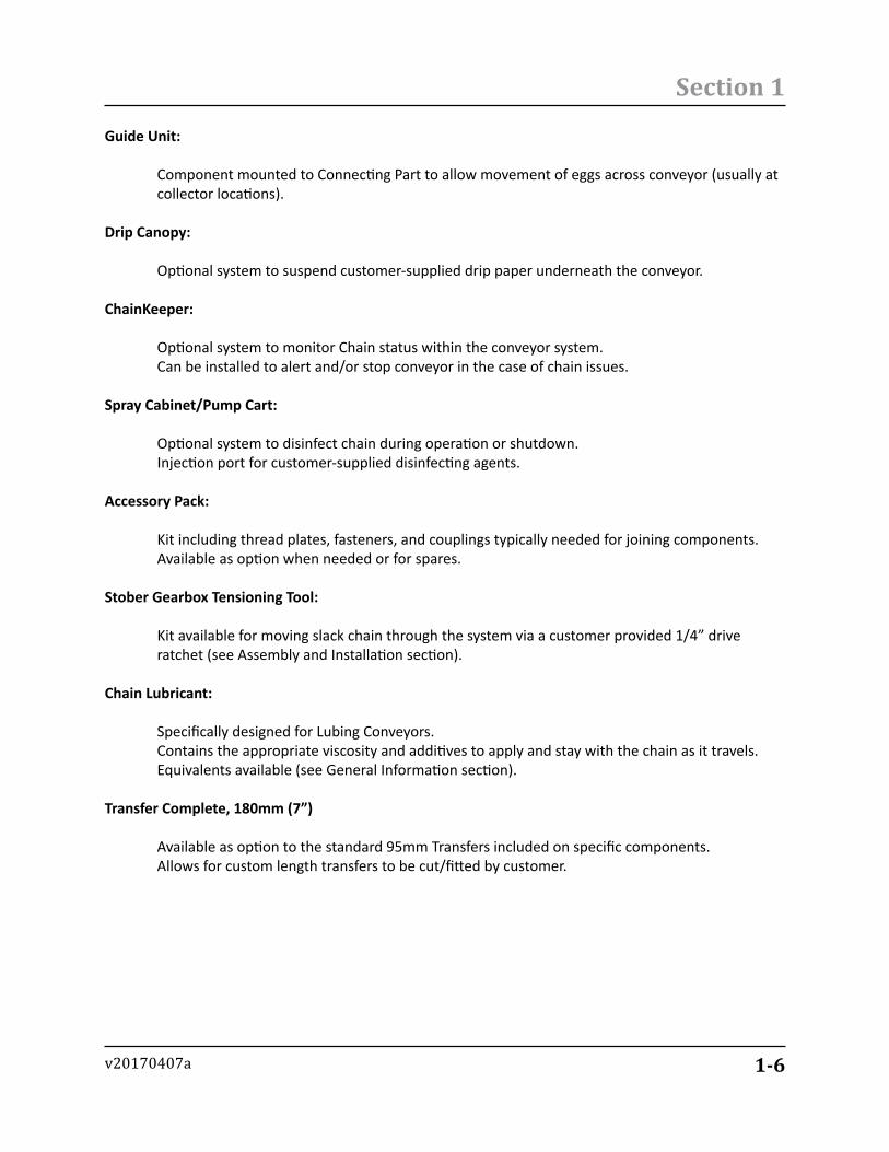
Guide Unit:
Component mounted to Connecting Part to allow movement of eggs across conveyor (usually at collector locations).
Drip Canopy:
Optional system to suspend customer-supplied drip paper underneath the conveyor.
ChainKeeper:
Optional system to monitor Chain status within the conveyor system. Can be installed to alert and/or stop conveyor in the case of chain issues.
Spray Cabinet/Pump Cart:
Optional system to disinfect chain during operation or shutdown. Injection port for customer-supplied disinfecting agents.
Accessory Pack:
Kit including thread plates, fasteners, and couplings typically needed for joining components. Available as option when needed or for spares.
Stober Gearbox Tensioning Tool:
Kit available for moving slack chain through the system via a customer provided 1/4” drive ratchet (see Assembly and Installation section).
Chain Lubricant:
Specifically designed for Lubing Conveyors. Contains the appropriate viscosity and additives to apply and stay with the chain as it travels. Equivalents available (see General Information section).
Transfer Complete, 180mm (7”)
Available as option to the standard 95mm Transfers included on specific components. Allows for custom length transfers to be cut/fitted by customer.
1-7
Section 1
v20170407a
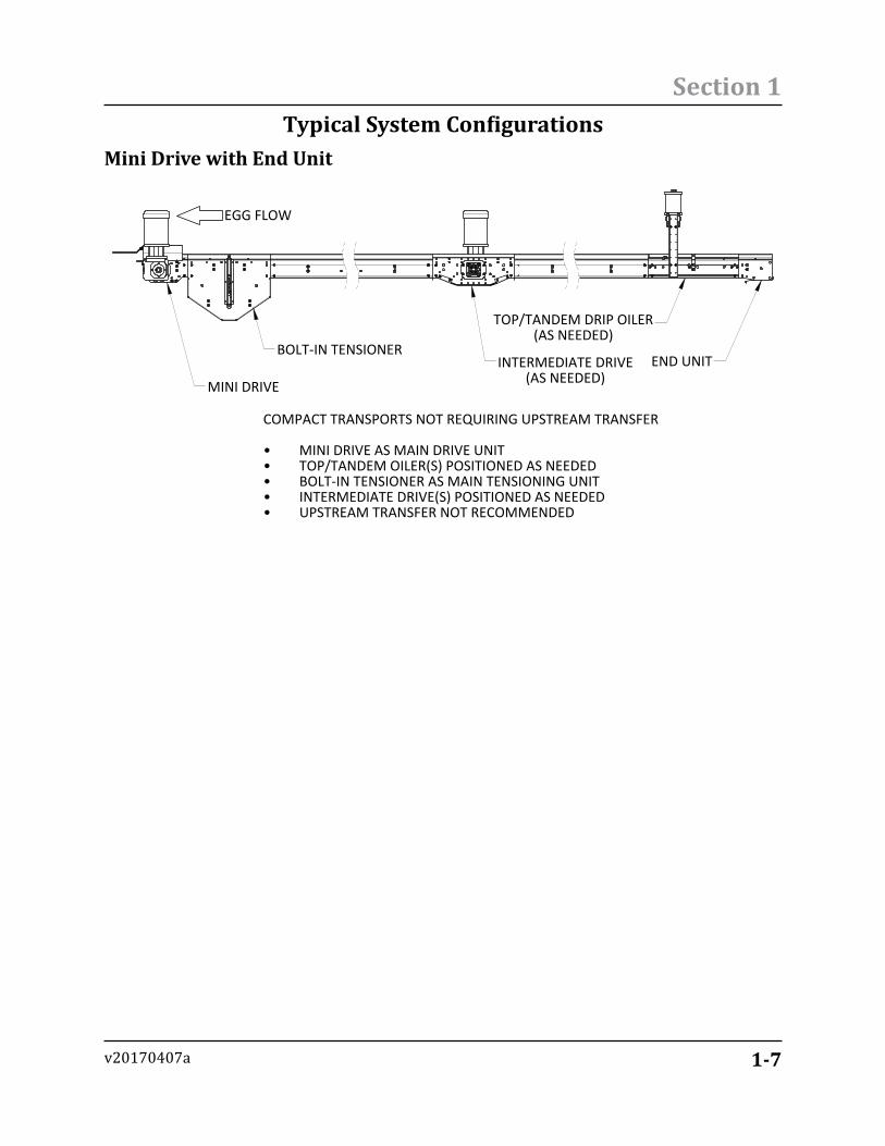
Mini Drive with End Unit
EGG FLOW
MINI DRIVE
BOLT-IN TENSIONERINTERMEDIATE DRIVE
(AS NEEDED)
TOP/TANDEM DRIP OILER(AS NEEDED)
END UNIT
COMPACT TRANSPORTS NOT REQUIRING UPSTREAM TRANSFER
MINI DRIVE AS MAIN DRIVE UNIT•TOP/TANDEM OILER(S) POSITIONED AS NEEDED•BOLT-IN TENSIONER AS MAIN TENSIONING UNIT•INTERMEDIATE DRIVE(S) POSITIONED AS NEEDED•UPSTREAM TRANSFER NOT RECOMMENDED•
Typical System Configurations
1-8
Section 1
v20170407a
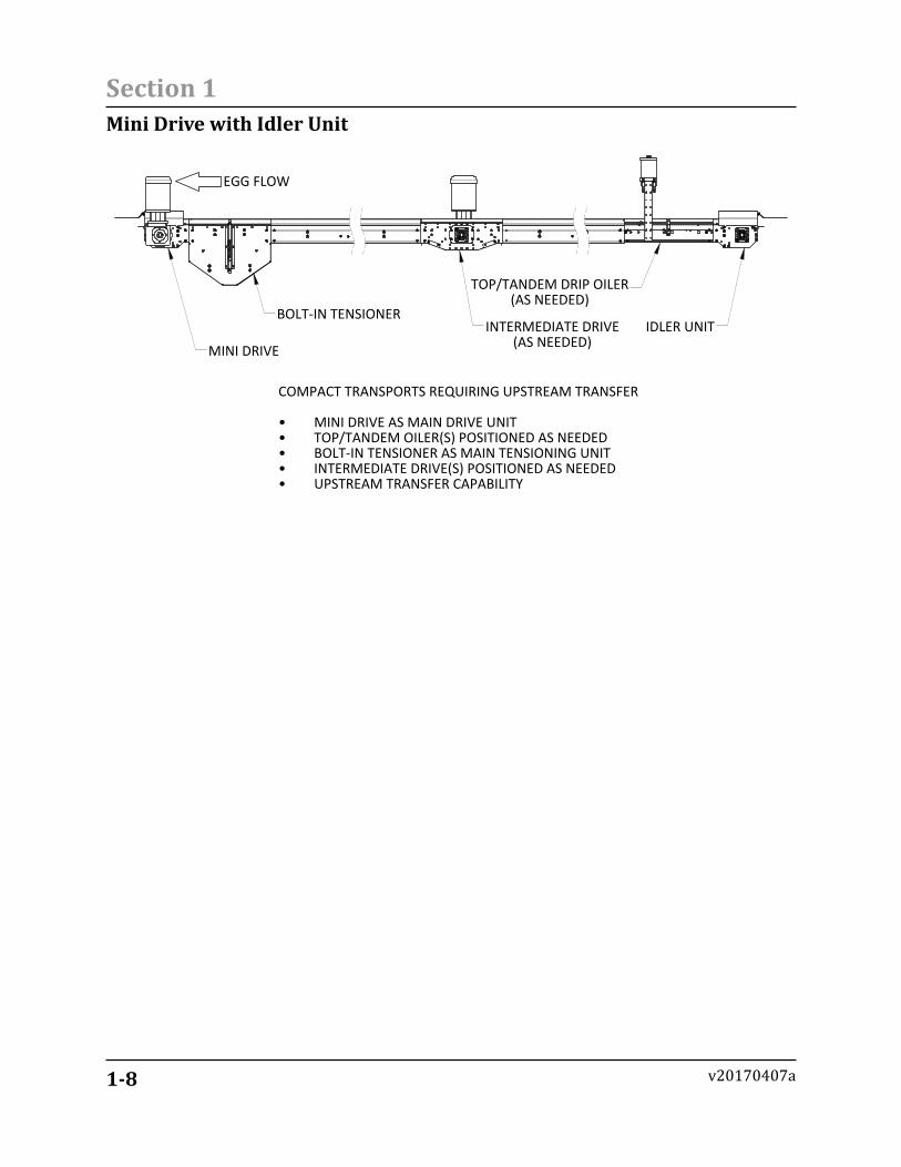
Mini Drive with Idler Unit
EGG FLOW
MINI DRIVE
BOLT-IN TENSIONERINTERMEDIATE DRIVE
(AS NEEDED)
TOP/TANDEM DRIP OILER(AS NEEDED)
IDLER UNIT
COMPACT TRANSPORTS REQUIRING UPSTREAM TRANSFER
MINI DRIVE AS MAIN DRIVE UNIT•TOP/TANDEM OILER(S) POSITIONED AS NEEDED•BOLT-IN TENSIONER AS MAIN TENSIONING UNIT•INTERMEDIATE DRIVE(S) POSITIONED AS NEEDED•UPSTREAM TRANSFER CAPABILITY•
1-9
Section 1
v20170407a
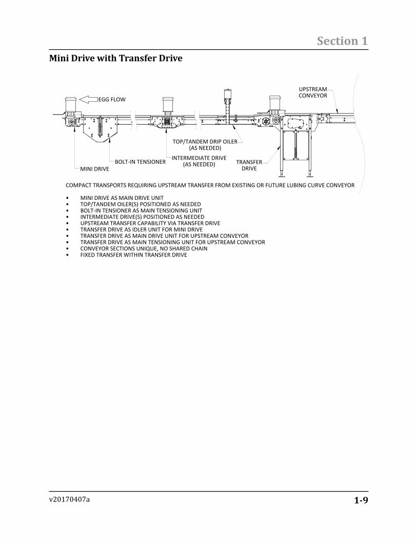
Mini Drive with Transfer Drive
EGG FLOW
MINI DRIVEBOLT-IN TENSIONER INTERMEDIATE DRIVE
(AS NEEDED)
TOP/TANDEM DRIP OILER(AS NEEDED)
TRANSFERDRIVE
COMPACT TRANSPORTS REQUIRING UPSTREAM TRANSFER FROM EXISTING OR FUTURE LUBING CURVE CONVEYOR
MINI DRIVE AS MAIN DRIVE UNIT•TOP/TANDEM OILER(S) POSITIONED AS NEEDED•BOLT-IN TENSIONER AS MAIN TENSIONING UNIT•INTERMEDIATE DRIVE(S) POSITIONED AS NEEDED•UPSTREAM TRANSFER CAPABILITY VIA TRANSFER DRIVE•TRANSFER DRIVE AS IDLER UNIT FOR MINI DRIVE•TRANSFER DRIVE AS MAIN DRIVE UNIT FOR UPSTREAM CONVEYOR•TRANSFER DRIVE AS MAIN TENSIONING UNIT FOR UPSTREAM CONVEYOR•CONVEYOR SECTIONS UNIQUE, NO SHARED CHAIN•FIXED TRANSFER WITHIN TRANSFER DRIVE•
UPSTREAMCONVEYOR
1-10
Section 1
v20170407a
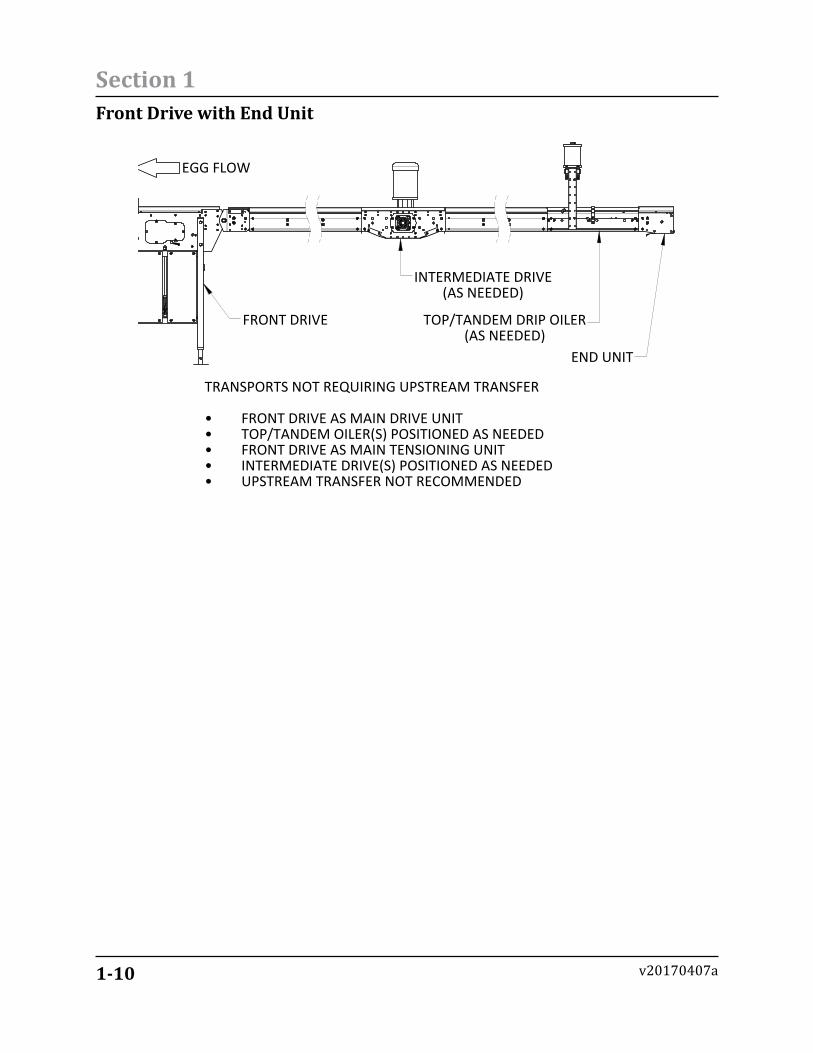
Front Drive with End Unit
EGG FLOW
FRONT DRIVE
INTERMEDIATE DRIVE(AS NEEDED)
TOP/TANDEM DRIP OILER(AS NEEDED)
END UNIT
TRANSPORTS NOT REQUIRING UPSTREAM TRANSFER
FRONT DRIVE AS MAIN DRIVE UNIT•TOP/TANDEM OILER(S) POSITIONED AS NEEDED•FRONT DRIVE AS MAIN TENSIONING UNIT•INTERMEDIATE DRIVE(S) POSITIONED AS NEEDED•UPSTREAM TRANSFER NOT RECOMMENDED•
1-11
Section 1
v20170407a
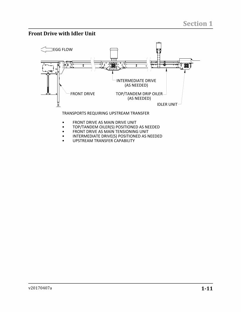
Front Drive with Idler Unit
EGG FLOW
FRONT DRIVE
INTERMEDIATE DRIVE(AS NEEDED)
TOP/TANDEM DRIP OILER(AS NEEDED)
IDLER UNIT
TRANSPORTS REQUIRING UPSTREAM TRANSFER
FRONT DRIVE AS MAIN DRIVE UNIT•TOP/TANDEM OILER(S) POSITIONED AS NEEDED•FRONT DRIVE AS MAIN TENSIONING UNIT•INTERMEDIATE DRIVE(S) POSITIONED AS NEEDED•UPSTREAM TRANSFER CAPABILITY•
1-12
Section 1
v20170407a
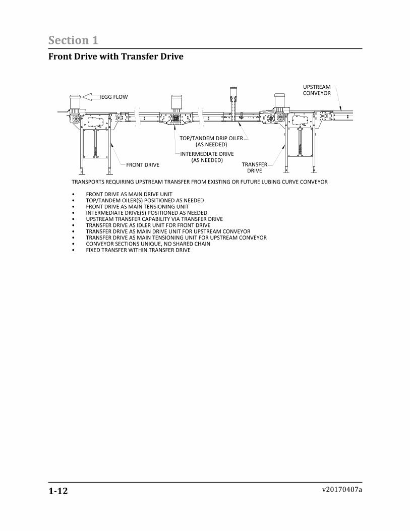
Front Drive with Transfer Drive
EGG FLOW
FRONT DRIVE
INTERMEDIATE DRIVE(AS NEEDED)
TOP/TANDEM DRIP OILER(AS NEEDED)
TRANSFERDRIVE
TRANSPORTS REQUIRING UPSTREAM TRANSFER FROM EXISTING OR FUTURE LUBING CURVE CONVEYOR
FRONT DRIVE AS MAIN DRIVE UNIT•TOP/TANDEM OILER(S) POSITIONED AS NEEDED•FRONT DRIVE AS MAIN TENSIONING UNIT•INTERMEDIATE DRIVE(S) POSITIONED AS NEEDED•UPSTREAM TRANSFER CAPABILITY VIA TRANSFER DRIVE•TRANSFER DRIVE AS IDLER UNIT FOR FRONT DRIVE•TRANSFER DRIVE AS MAIN DRIVE UNIT FOR UPSTREAM CONVEYOR•TRANSFER DRIVE AS MAIN TENSIONING UNIT FOR UPSTREAM CONVEYOR•CONVEYOR SECTIONS UNIQUE, NO SHARED CHAIN•FIXED TRANSFER WITHIN TRANSFER DRIVE•
UPSTREAMCONVEYOR
1-13
Section 1
v20170407a
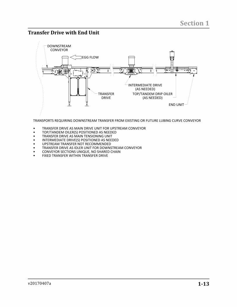
Transfer Drive with End Unit
EGG FLOW
DOWNSTREAMCONVEYOR
TRANSFERDRIVE
INTERMEDIATE DRIVE(AS NEEDED)
TOP/TANDEM DRIP OILER(AS NEEDED)
END UNIT
TRANSPORTS REQUIRING DOWNSTREAM TRANSFER FROM EXISTING OR FUTURE LUBING CURVE CONVEYOR
TRANSFER DRIVE AS MAIN DRIVE UNIT FOR UPSTREAM CONVEYOR•TOP/TANDEM OILER(S) POSITIONED AS NEEDED•TRANSFER DRIVE AS MAIN TENSIONING UNIT•INTERMEDIATE DRIVE(S) POSITIONED AS NEEDED•UPSTREAM TRANSFER NOT RECOMMENDED•TRANSFER DRIVE AS IDLER UNIT FOR DOWNSTREAM CONVEYOR•CONVEYOR SECTIONS UNIQUE, NO SHARED CHAIN•FIXED TRANSFER WITHIN TRANSFER DRIVE•
1-14
Section 1
v20170407a
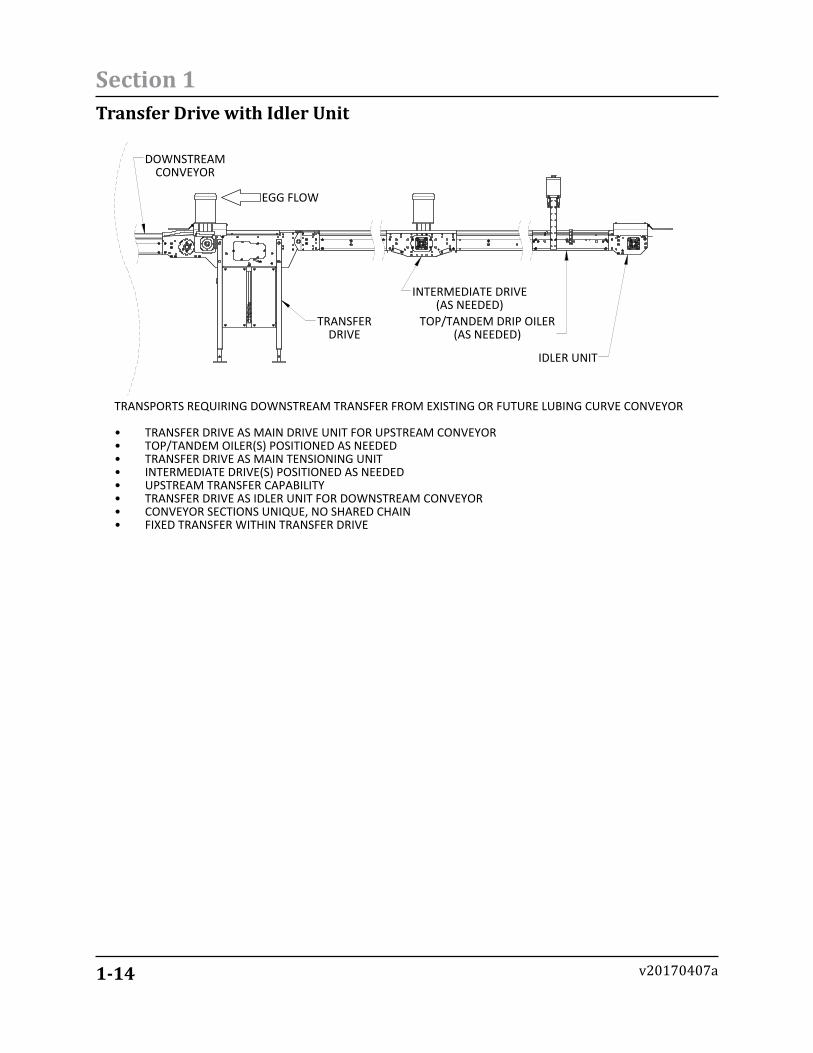
Transfer Drive with Idler Unit
EGG FLOW
DOWNSTREAMCONVEYOR
TRANSFERDRIVE
INTERMEDIATE DRIVE(AS NEEDED)
TOP/TANDEM DRIP OILER(AS NEEDED)
IDLER UNIT
TRANSPORTS REQUIRING DOWNSTREAM TRANSFER FROM EXISTING OR FUTURE LUBING CURVE CONVEYOR
TRANSFER DRIVE AS MAIN DRIVE UNIT FOR UPSTREAM CONVEYOR•TOP/TANDEM OILER(S) POSITIONED AS NEEDED•TRANSFER DRIVE AS MAIN TENSIONING UNIT•INTERMEDIATE DRIVE(S) POSITIONED AS NEEDED•UPSTREAM TRANSFER CAPABILITY•TRANSFER DRIVE AS IDLER UNIT FOR DOWNSTREAM CONVEYOR•CONVEYOR SECTIONS UNIQUE, NO SHARED CHAIN•FIXED TRANSFER WITHIN TRANSFER DRIVE•
1-15
Section 1
v20170407a
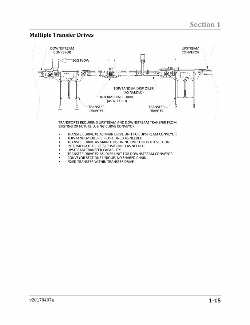
Multiple Transfer Drives
EGG FLOW
TRANSFERDRIVE #1
TRANSFERDRIVE #2
TOP/TANDEM DRIP OILER(AS NEEDED)
INTERMEDIATE DRIVE(AS NEEDED)
DOWNSTREAMCONVEYOR
UPSTREAMCONVEYOR
TRANSPORTS REQUIRING UPSTREAM AND DOWNSTREAM TRANSFER FROMEXISTING OR FUTURE LUBING CURVE CONVEYOR
TRANSFER DRIVE #1 AS MAIN DRIVE UNIT FOR UPSTREAM CONVEYOR•TOP/TANDEM OILER(S) POSITIONED AS NEEDED•TRANSFER DRIVE AS MAIN TENSIONING UNIT FOR BOTH SECTIONS•INTERMEDIATE DRIVE(S) POSITIONED AS NEEDED•UPSTREAM TRANSFER CAPABILITY•TRANSFER DRIVE #2 AS IDLER UNIT FOR DOWNSTREAM CONVEYOR•CONVEYOR SECTIONS UNIQUE, NO SHARED CHAIN•FIXED TRANSFER WITHIN TRANSFER DRIVE•
1-16
Section 1
v20170407a
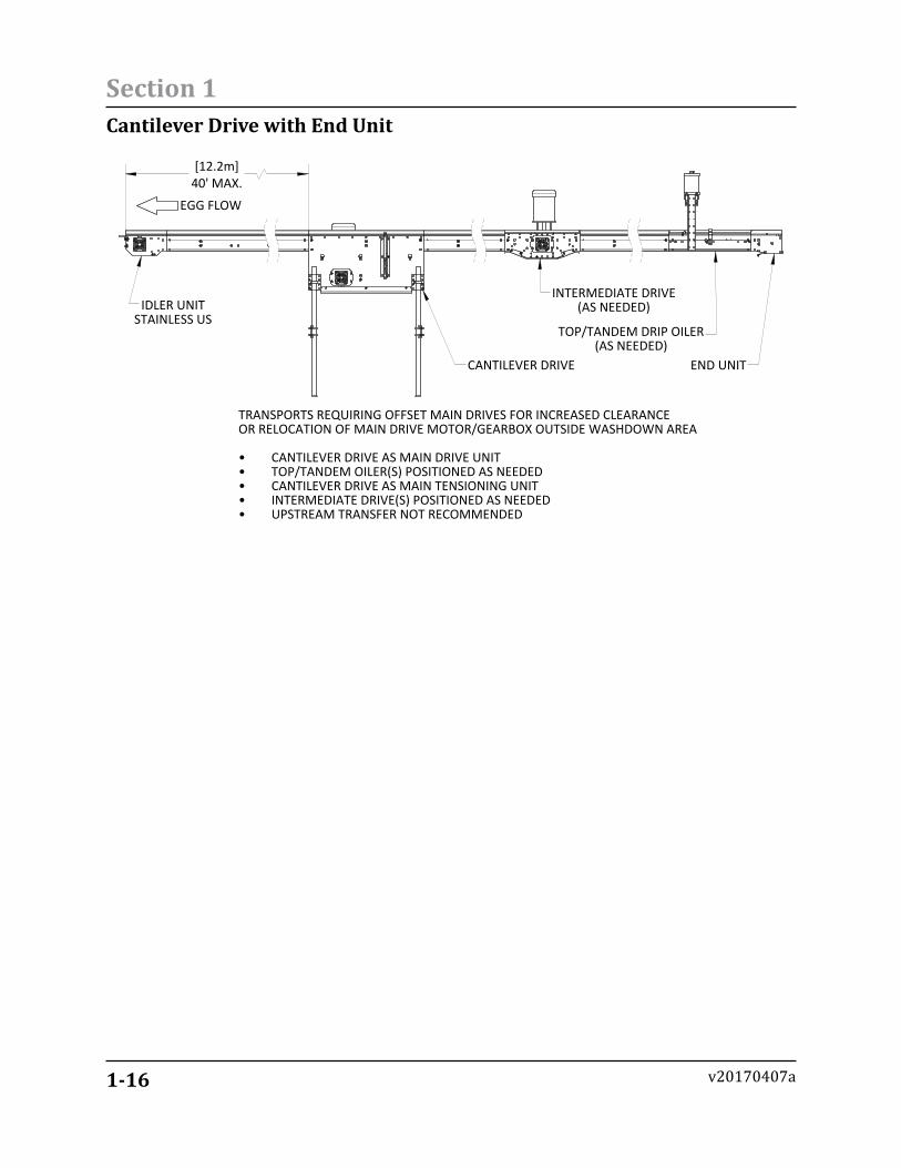
Cantilever Drive with End Unit
[12.2m]40' MAX.
EGG FLOW
CANTILEVER DRIVE
INTERMEDIATE DRIVE(AS NEEDED)
TOP/TANDEM DRIP OILER(AS NEEDED)
END UNIT
TRANSPORTS REQUIRING OFFSET MAIN DRIVES FOR INCREASED CLEARANCEOR RELOCATION OF MAIN DRIVE MOTOR/GEARBOX OUTSIDE WASHDOWN AREA
CANTILEVER DRIVE AS MAIN DRIVE UNIT•TOP/TANDEM OILER(S) POSITIONED AS NEEDED•CANTILEVER DRIVE AS MAIN TENSIONING UNIT•INTERMEDIATE DRIVE(S) POSITIONED AS NEEDED•UPSTREAM TRANSFER NOT RECOMMENDED•
IDLER UNITSTAINLESS US
1-17
Section 1
v20170407a
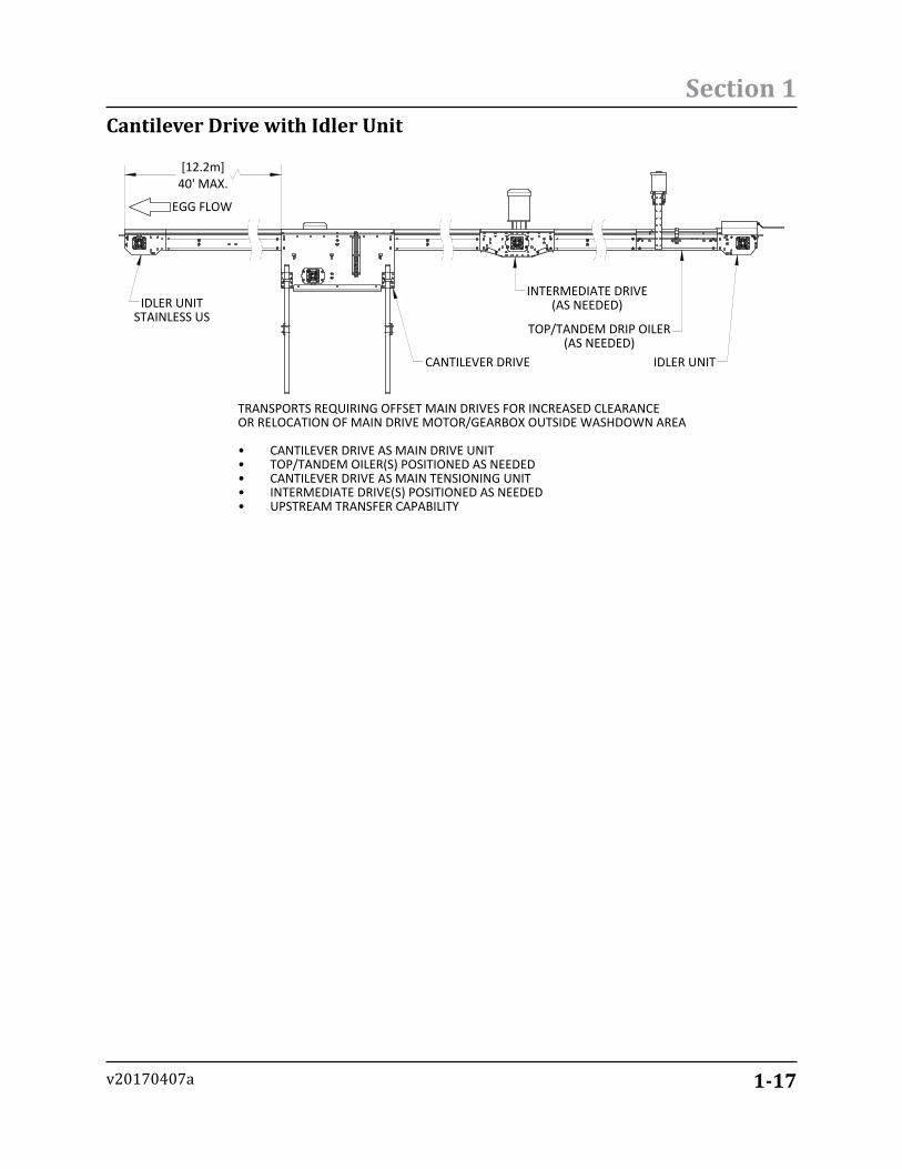
Cantilever Drive with Idler Unit
[12.2m]40' MAX.
EGG FLOW
CANTILEVER DRIVE
INTERMEDIATE DRIVE(AS NEEDED)
TOP/TANDEM DRIP OILER(AS NEEDED)
IDLER UNIT
TRANSPORTS REQUIRING OFFSET MAIN DRIVES FOR INCREASED CLEARANCEOR RELOCATION OF MAIN DRIVE MOTOR/GEARBOX OUTSIDE WASHDOWN AREA
CANTILEVER DRIVE AS MAIN DRIVE UNIT•TOP/TANDEM OILER(S) POSITIONED AS NEEDED•CANTILEVER DRIVE AS MAIN TENSIONING UNIT•INTERMEDIATE DRIVE(S) POSITIONED AS NEEDED•UPSTREAM TRANSFER CAPABILITY•
IDLER UNITSTAINLESS US