Embed Size (px)
Citation preview
Fundamentals of Vibration Isolation
12/8/99 MEIT-99 / Section 14 / Page 1
Section 14:Fundamentals of Vibration Isolation
Presented by:
Richard DeLombard
NASA Glenn ResearchCenterMaterial originally prepared by:
Dr. Mark Whorton
Principal Investigator for g-LIMIT
NASA Marshall Space Flight Center
Fundamentals of Vibration Isolation
12/8/99 MEIT-99 / Section 14 / Page 2
Outline:
• Vibration Isolation Technology• Dynamics of Systems• Active Control Concepts• Isolation Performance Measures
• Flight Hardware Systems• STABLE• MIM• ARIS• g-LIMIT
Fundamentals of Vibration Isolation
12/8/99 MEIT-99 / Section 14 / Page 3
Introduction
• The ambient spacecraft acceleration levels are often higherthan allowable from a science perspective.
• To reduce the acceleration levels to an acceptably quiescentlevel requires vibration isolation.
• Either passive or active isolation can be used depending onthe needs or requirements of a specific application.
Fundamentals of Vibration Isolation
12/8/99 MEIT-99 / Section 14 / Page 4
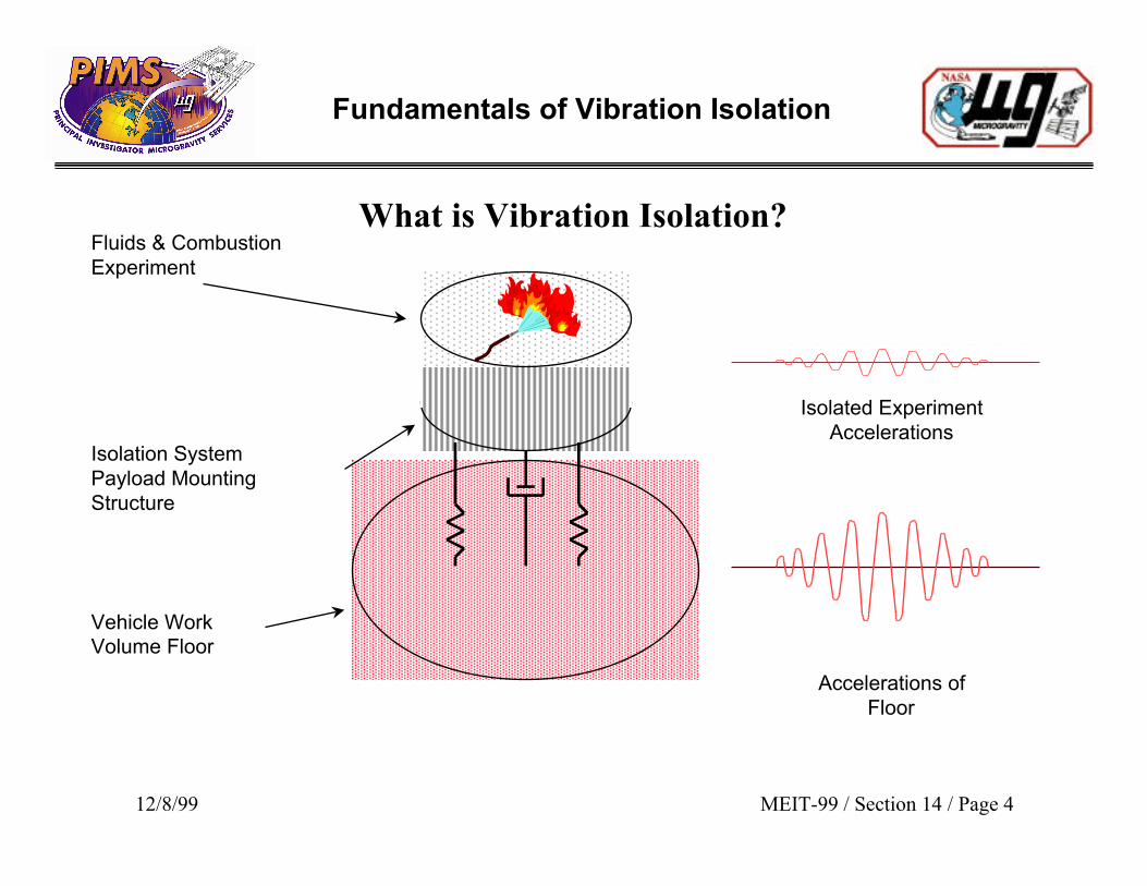
What is Vibration Isolation?
Vehicle Work Volume Floor
Isolation SystemPayload MountingStructure
Accelerations ofFloor
Fluids & CombustionExperiment
Isolated ExperimentAccelerations
Fundamentals of Vibration Isolation
12/8/99 MEIT-99 / Section 14 / Page 5
System Dynamics: Transmissibility
• The transmissibility is the transfer function that relates theacceleration (or position) response of the mass to the base acceleration(or position) input.• The magnitude of the transmissibility function specifies theattenuation of base motion as a function of frequency.• Use of springs, masses, and dampers for attenuation is known as“passive vibration isolation”
Fundamentals of Vibration Isolation
12/8/99 MEIT-99 / Section 14 / Page 6
Active Control Concepts
• Active vibration isolation seeks to minimize the inertial motion of thepayload by directly sensing the inertial motion and applying forces tothe platform to directly counter the measured motion.
• Using a passive isolation analogy, active control can effectivelychange the system mass, stiffness and damping and thus change thedynamics -- i.e. the time response of the system.
Fundamentals of Vibration Isolation
12/8/99 MEIT-99 / Section 14 / Page 7
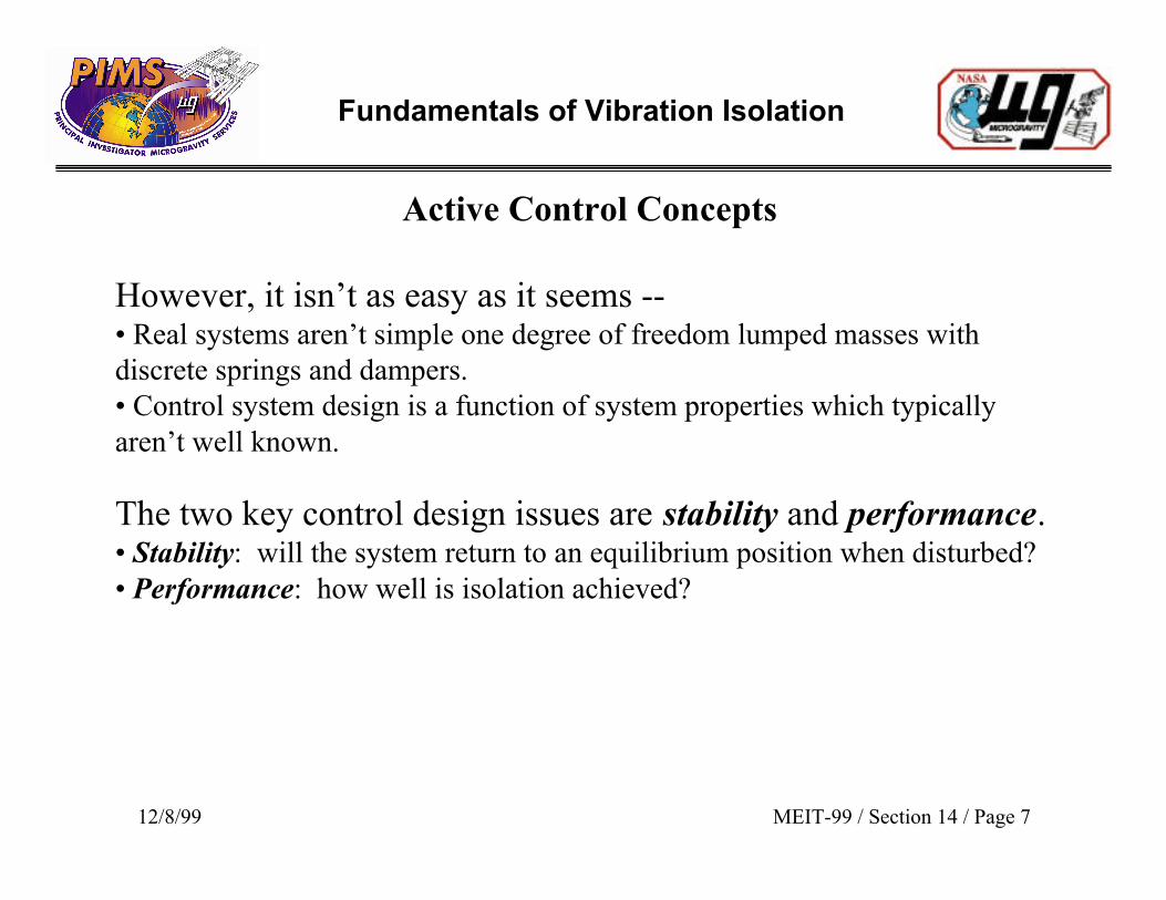
Active Control Concepts
However, it isn’t as easy as it seems --• Real systems aren’t simple one degree of freedom lumped masses withdiscrete springs and dampers.• Control system design is a function of system properties which typicallyaren’t well known.
The two key control design issues are stability and performance.• Stability: will the system return to an equilibrium position when disturbed?• Performance: how well is isolation achieved?
Fundamentals of Vibration Isolation
12/8/99 MEIT-99 / Section 14 / Page 8
Active Control Concepts
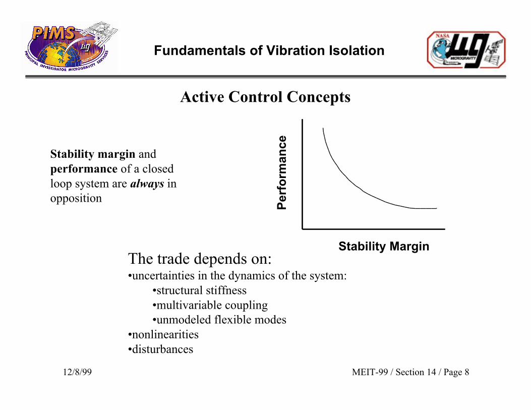
Stability margin andperformance of a closedloop system are always inopposition
Pe
rfo
rma
nc
e
Stability MarginThe trade depends on:•uncertainties in the dynamics of the system:
•structural stiffness•multivariable coupling•unmodeled flexible modes
•nonlinearities•disturbances
Fundamentals of Vibration Isolation
12/8/99 MEIT-99 / Section 14 / Page 9
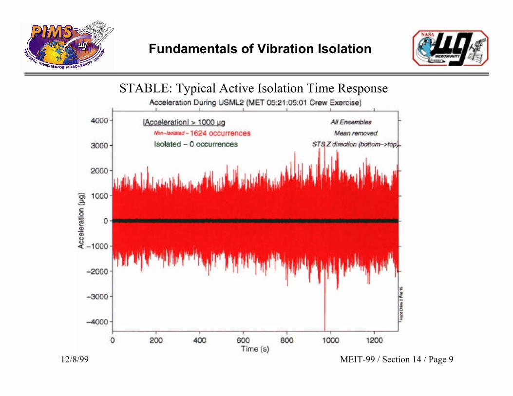
STABLE: Typical Active Isolation Time Response
Fundamentals of Vibration Isolation
12/8/99 MEIT-99 / Section 14 / Page 10
10-2
10-1
100
101
102
103
10-2
10-1
100
101
102
103
104
105
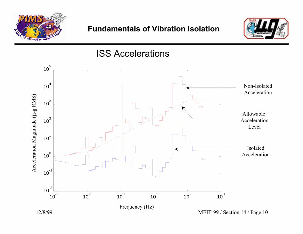
Allowable Acceleration
Level
Non-IsolatedAcceleration
IsolatedAcceleration
ISS Accelerations
Frequency (Hz)
Acc
eler
atio
n M
agni
tude
(µ-
g R
MS
)
Fundamentals of Vibration Isolation
12/8/99 MEIT-99 / Section 14 / Page 11
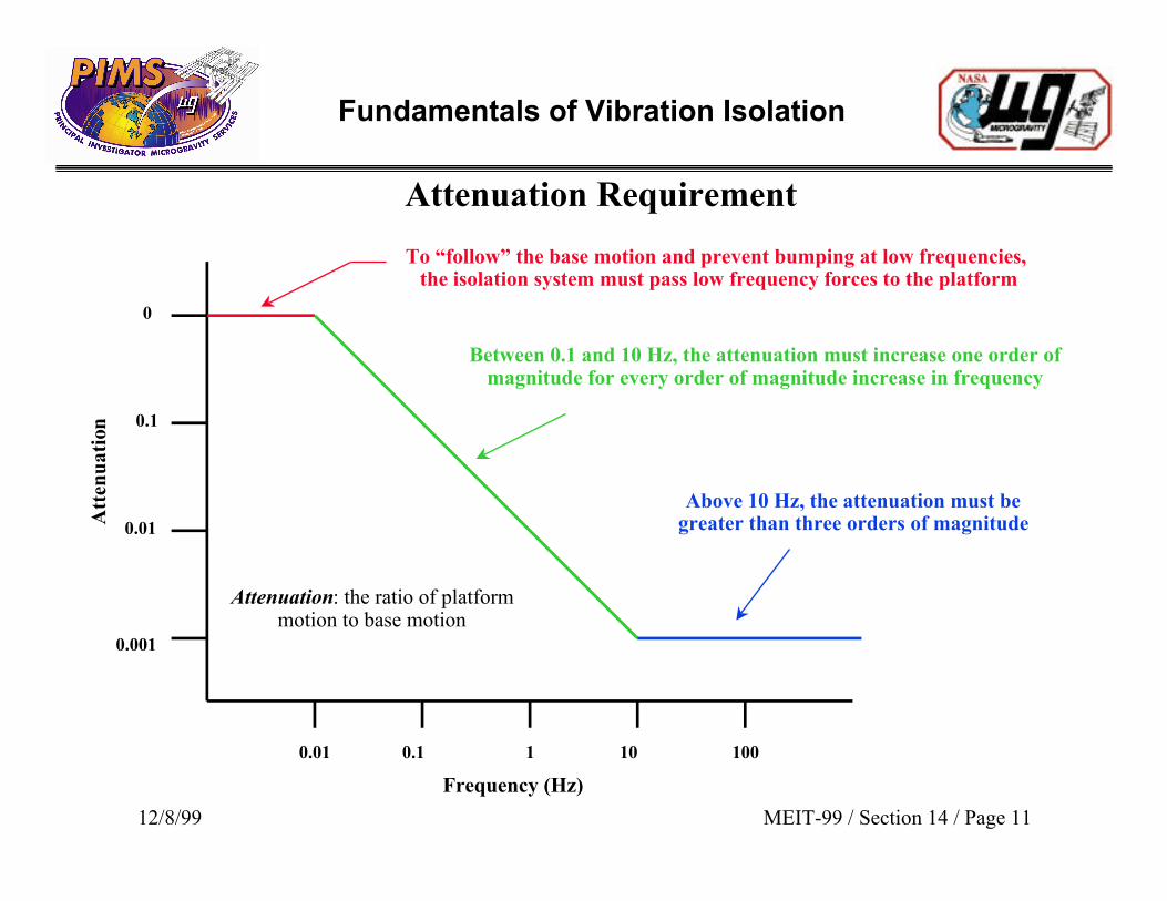
Attenuation Requirement
Between 0.1 and 10 Hz, the attenuation must increase one order ofmagnitude for every order of magnitude increase in frequency
Attenuation: the ratio of platformmotion to base motion
Att
enu
atio
n
0.01
Frequency (Hz)
To “follow” the base motion and prevent bumping at low frequencies, the isolation system must pass low frequency forces to the platform
0.1
Above 10 Hz, the attenuation must begreater than three orders of magnitude
1 10 100
0
0.1
0.01
0.001
Fundamentals of Vibration Isolation
12/8/99 MEIT-99 / Section 14 / Page 12
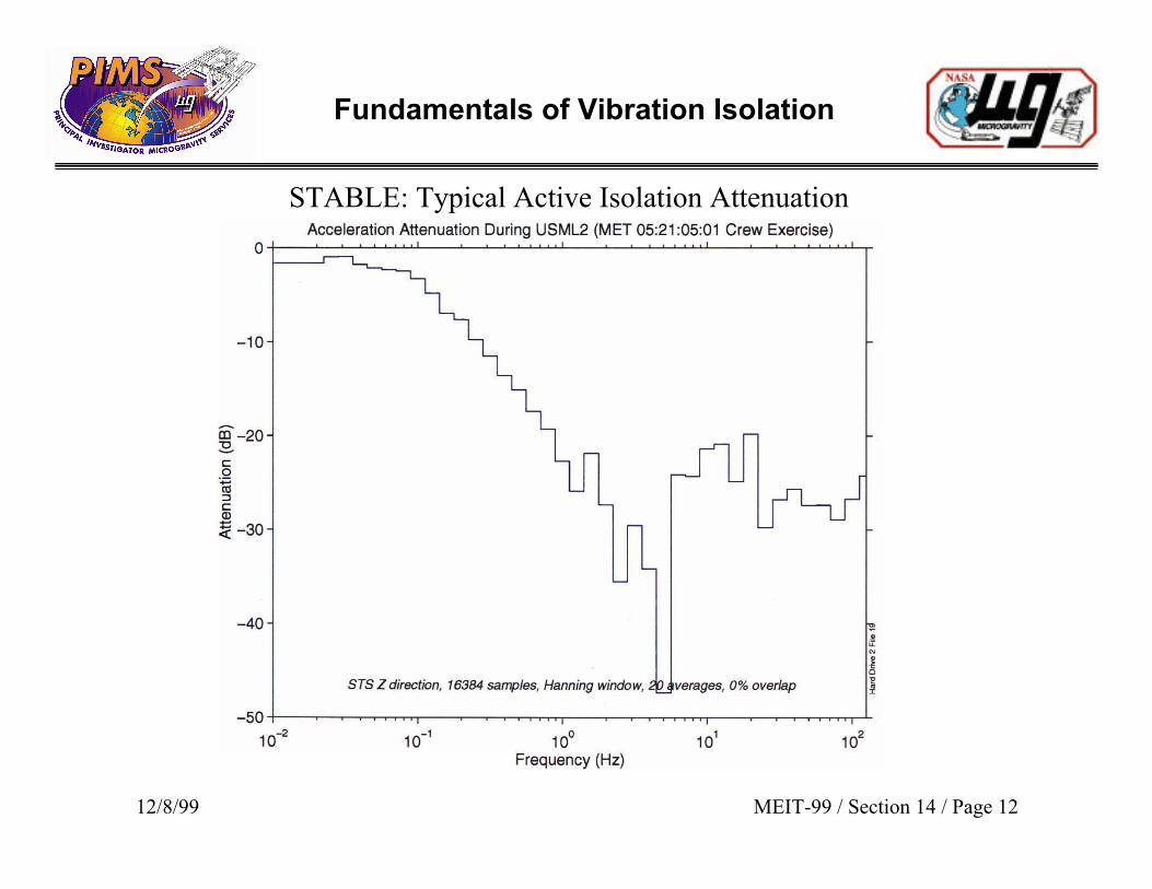
STABLE: Typical Active Isolation Attenuation
Fundamentals of Vibration Isolation
12/8/99 MEIT-99 / Section 14 / Page 13
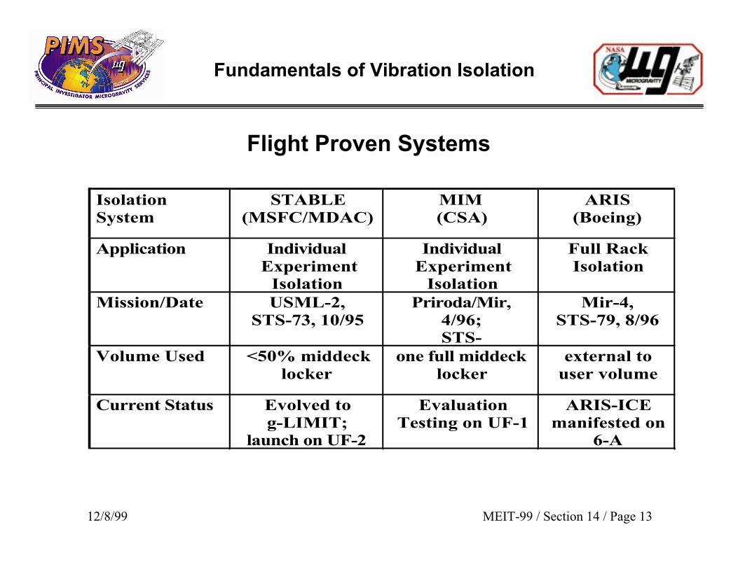
Flight Proven Systems
IsolationSystem
STABLE(MSFC/MDAC)
MIM(CSA)
ARIS(Boeing)
Application IndividualExperiment
Isolation
IndividualExperiment
Isolation
Full RackIsolation
Mission/Date USML-2,STS-73, 10/95
Priroda/Mir,4/96;STS-
Mir-4,STS-79, 8/96
Volume Used <50% middecklocker
one full middecklocker
external touser volume
Current Status Evolved tog-LIMIT;
launch on UF-2
EvaluationTesting on UF-1
ARIS-ICEmanifested on
6-A
Fundamentals of Vibration Isolation
12/8/99 MEIT-99 / Section 14 / Page 14
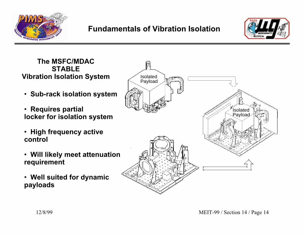
The MSFC/MDACSTABLE
Vibration Isolation System
• Sub-rack isolation system
• Requires partiallocker for isolation system
• High frequency activecontrol
• Will likely meet attenuationrequirement
• Well suited for dynamicpayloads
Isolated Payload
Isolated Payload
Fundamentals of Vibration Isolation
12/8/99 MEIT-99 / Section 14 / Page 15
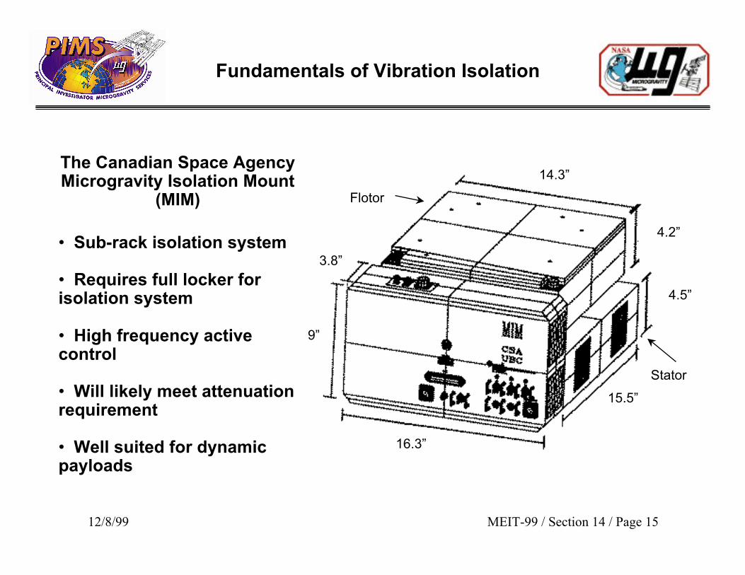
Stator
Flotor
15.5”
16.3”
9”
3.8”
14.3”
4.2”
4.5”
The Canadian Space AgencyMicrogravity Isolation Mount
(MIM)
• Sub-rack isolation system
• Requires full locker forisolation system
• High frequency activecontrol
• Will likely meet attenuationrequirement
• Well suited for dynamicpayloads
Fundamentals of Vibration Isolation
12/8/99 MEIT-99 / Section 14 / Page 16
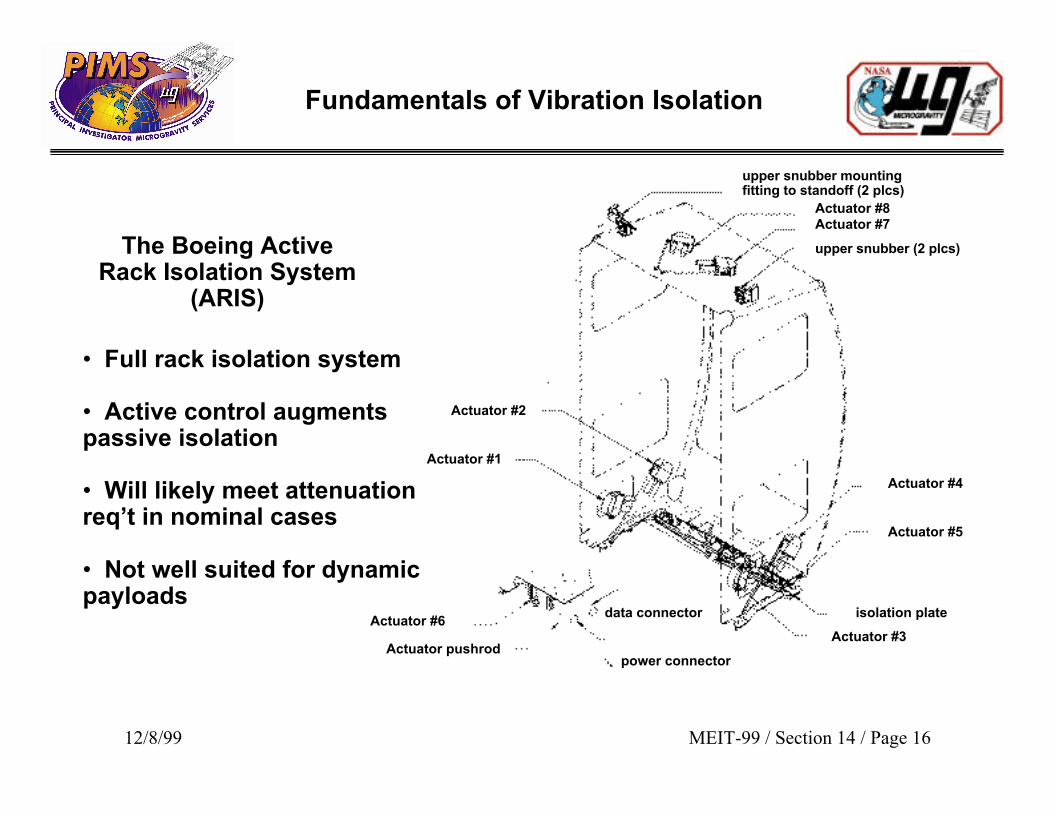
data connector
upper snubber mountingfitting to standoff (2 plcs)
Actuator #8Actuator #7
upper snubber (2 plcs)
Actuator #3
Actuator #5
Actuator #4
isolation plate
power connectorActuator pushrod
Actuator #6
Actuator #1
Actuator #2
The Boeing ActiveRack Isolation System
(ARIS)
• Full rack isolation system
• Active control augmentspassive isolation
• Will likely meet attenuationreq’t in nominal cases
• Not well suited for dynamicpayloads
Fundamentals of Vibration Isolation
12/8/99 MEIT-99 / Section 14 / Page 17
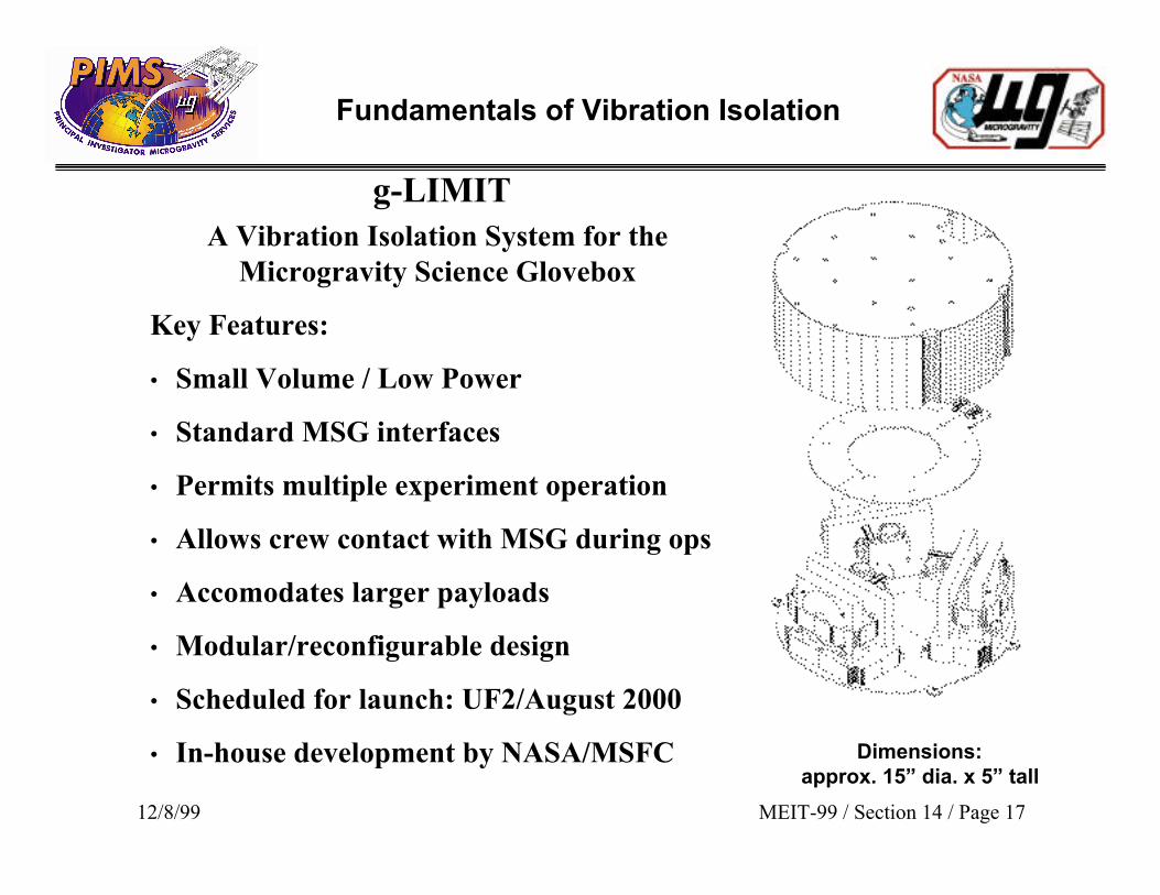
Dimensions:approx. 15” dia. x 5” tall
g-LIMITA Vibration Isolation System for the
Microgravity Science Glovebox
Key Features:
• Small Volume / Low Power
• Standard MSG interfaces
• Permits multiple experiment operation
• Allows crew contact with MSG during ops
• Accomodates larger payloads
• Modular/reconfigurable design
• Scheduled for launch: UF2/August 2000
• In-house development by NASA/MSFC
Fundamentals of Vibration Isolation
12/8/99 MEIT-99 / Section 14 / Page 18
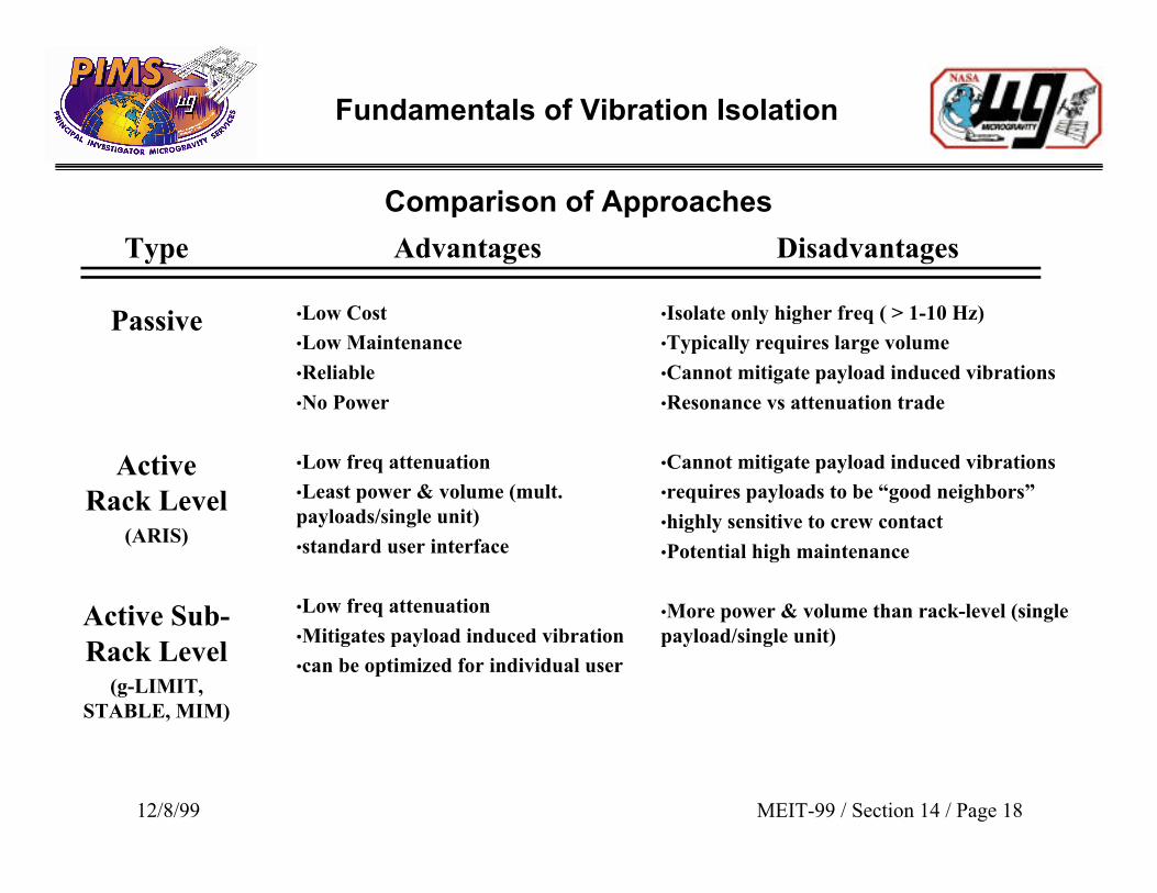
Comparison of Approaches
Advantages
•Low Cost
•Low Maintenance
•Reliable
•No Power
•Low freq attenuation
•Least power & volume (mult.payloads/single unit)
•standard user interface
•Low freq attenuation
•Mitigates payload induced vibration
•can be optimized for individual user
Disadvantages
•Isolate only higher freq ( > 1-10 Hz)
•Typically requires large volume
•Cannot mitigate payload induced vibrations
•Resonance vs attenuation trade
•Cannot mitigate payload induced vibrations
•requires payloads to be “good neighbors”
•highly sensitive to crew contact
•Potential high maintenance
•More power & volume than rack-level (singlepayload/single unit)
Type
Passive
ActiveRack Level
(ARIS)
Active Sub-Rack Level
(g-LIMIT,STABLE, MIM)