Embed Size (px)
Citation preview
KNOXVILLE UTILITIES BOARD
STANDARDS AND SPECIFICATIONS
10/28/2013 Cathodic Protection Test Points & Anode Installations for Natural Gas Pipeline 15500- 1
SECTION 15500
CATHODIC PROTECTION TEST POINTS AND
ANODE INSTALLATIONS FOR NATURAL GAS PIPELINE
PART 1. GENERAL
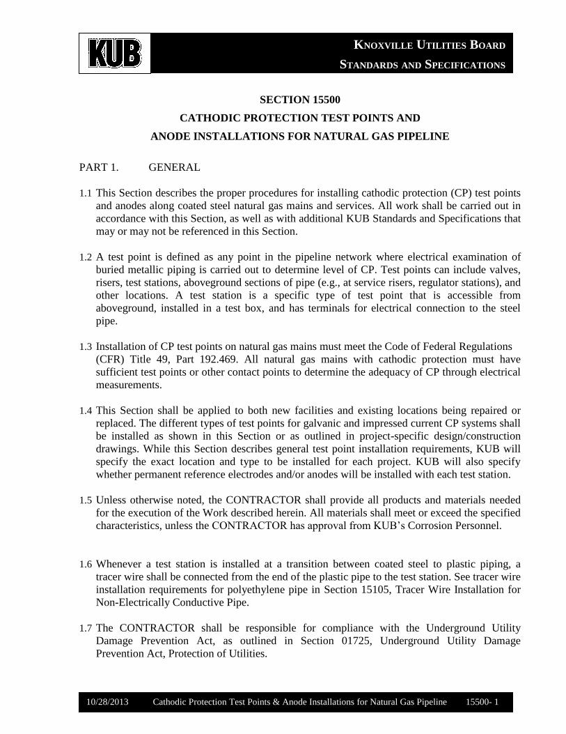
1.1 This Section describes the proper procedures for installing cathodic protection (CP) test points
and anodes along coated steel natural gas mains and services. All work shall be carried out in
accordance with this Section, as well as with additional KUB Standards and Specifications that
may or may not be referenced in this Section.
1.2 A test point is defined as any point in the pipeline network where electrical examination of
buried metallic piping is carried out to determine level of CP. Test points can include valves,
risers, test stations, aboveground sections of pipe (e.g., at service risers, regulator stations), and
other locations. A test station is a specific type of test point that is accessible from
aboveground, installed in a test box, and has terminals for electrical connection to the steel
pipe.
1.3 Installation of CP test points on natural gas mains must meet the Code of Federal Regulations
(CFR) Title 49, Part 192.469. All natural gas mains with cathodic protection must have
sufficient test points or other contact points to determine the adequacy of CP through electrical
measurements.
1.4 This Section shall be applied to both new facilities and existing locations being repaired or
replaced. The different types of test points for galvanic and impressed current CP systems shall
be installed as shown in this Section or as outlined in project-specific design/construction
drawings. While this Section describes general test point installation requirements, KUB will
specify the exact location and type to be installed for each project. KUB will also specify
whether permanent reference electrodes and/or anodes will be installed with each test station.
1.5 Unless otherwise noted, the CONTRACTOR shall provide all products and materials needed
for the execution of the Work described herein. All materials shall meet or exceed the specified
characteristics, unless the CONTRACTOR has approval from KUB’s Corrosion Personnel.
1.6 Whenever a test station is installed at a transition between coated steel to plastic piping, a
tracer wire shall be connected from the end of the plastic pipe to the test station. See tracer wire
installation requirements for polyethylene pipe in Section 15105, Tracer Wire Installation for
Non-Electrically Conductive Pipe.
1.7 The CONTRACTOR shall be responsible for compliance with the Underground Utility
Damage Prevention Act, as outlined in Section 01725, Underground Utility Damage
Prevention Act, Protection of Utilities.
KNOXVILLE UTILITIES BOARD
STANDARDS AND SPECIFICATIONS
10/28/2013 Cathodic Protection Test Points & Anode Installations for Natural Gas Pipeline 15500- 2
1.8 The CONTRACTOR shall be responsible for meeting all safety requirements, including, but
not limited to, those included in Section 00700, Part 6.13.
1.9 The CONTRACTOR shall be responsible for meeting all applicable Operator Qualification
requirements.
PART 2. PRODUCTS
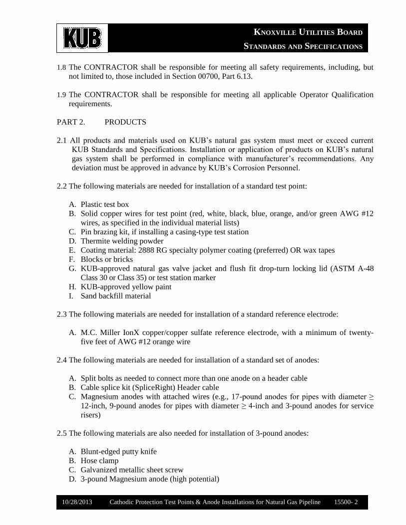
2.1 All products and materials used on KUB’s natural gas system must meet or exceed current
KUB Standards and Specifications. Installation or application of products on KUB’s natural
gas system shall be performed in compliance with manufacturer’s recommendations. Any
deviation must be approved in advance by KUB’s Corrosion Personnel.
2.2 The following materials are needed for installation of a standard test point:
A. Plastic test box
B. Solid copper wires for test point (red, white, black, blue, orange, and/or green AWG #12
wires, as specified in the individual material lists)
C. Pin brazing kit, if installing a casing-type test station
D. Thermite welding powder
E. Coating material: 2888 RG specialty polymer coating (preferred) OR wax tapes
F. Blocks or bricks
G. KUB-approved natural gas valve jacket and flush fit drop-turn locking lid (ASTM A-48
Class 30 or Class 35) or test station marker
H. KUB-approved yellow paint
I. Sand backfill material
2.3 The following materials are needed for installation of a standard reference electrode:
A. M.C. Miller IonX copper/copper sulfate reference electrode, with a minimum of twenty-
five feet of AWG #12 orange wire
2.4 The following materials are needed for installation of a standard set of anodes:
A. Split bolts as needed to connect more than one anode on a header cable
B. Cable splice kit (SpliceRight) Header cable
C. Magnesium anodes with attached wires (e.g., 17-pound anodes for pipes with diameter ≥
12-inch, 9-pound anodes for pipes with diameter ≥ 4-inch and 3-pound anodes for service
risers)
2.5 The following materials are also needed for installation of 3-pound anodes:
A. Blunt-edged putty knife
B. Hose clamp
C. Galvanized metallic sheet screw
D. 3-pound Magnesium anode (high potential)
KNOXVILLE UTILITIES BOARD
STANDARDS AND SPECIFICATIONS
10/28/2013 Cathodic Protection Test Points & Anode Installations for Natural Gas Pipeline 15500- 3
Additional materials may be required for specific types of test points, as outlined in material
lists included herein.
2.6 The following minimum tools and equipment will be necessary to complete the tasks:
A. Excavation equipment
B. Wire brush or metal file
C. Flint gun for ignition of thermite
D. Exothermic welding furnace
E. Flathead screw driver, pliers, and wrenches
PART 3. EXECUTION
3.1 This Section outlines the procedures for installing test points, reference electrodes, and anodes.
The following requirements apply to all types of test points:
A. Test points shall not be installed where accessibility would be difficult or unsafe, such as
under buildings, permanent structures, proposed future structures, or in high traffic areas.
B. To prevent electrical shorts or reduce the influence of stray current, test points shall be
installed with at least 36 inches of clearance from any other underground structure. If
clearance cannot be obtained, CONTRACTOR shall notify OWNER’s Corrosion
Personnel.
C. For all installations, once the pipe has been exposed, complete a Corrosion Observation and
a pipe-to-soil potential reading, documenting the results on a Corrosion Card or Natural
Gas Utility Service Sheet (NGUSS). The completed form shall be given to the KUB’s
Corrosion Personnel or RPR as soon as work is completed.
D. The CONTRACTOR shall notify the OWNER’s Corrosion Personnel when test stations
and other types of test points are ready for final hookup. To facilitate testing, any anode
wires shall remain attached to the pin (not yet connected to wire from the pipe). Corrosion
Personnel will conduct tests to make sure that none of the anodes or wires is damaged or
broken. If tests indicate damage, the entire wire and/or anode shall be replaced and retested
at the CONTRACTOR’s expense.
3.2 Procedures to Install a Standard Test Station
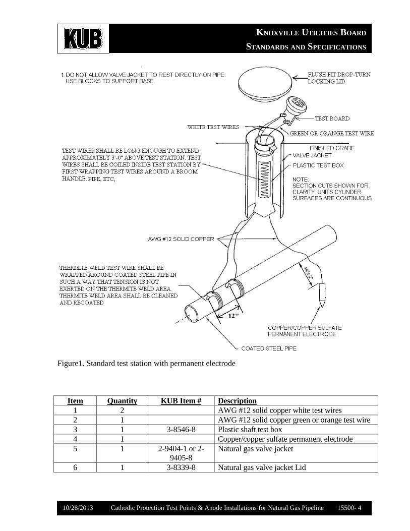
The basic installation of a standard test station is shown in Figure 1, along with an associated
materials list.
KNOXVILLE UTILITIES BOARD
STANDARDS AND SPECIFICATIONS
10/28/2013 Cathodic Protection Test Points & Anode Installations for Natural Gas Pipeline 15500- 4
Figure1. Standard test station with permanent electrode
Item Quantity KUB Item # Description
1 2 AWG #12 solid copper white test wires
2 1 AWG #12 solid copper green or orange test wire
3 1 3-8546-8 Plastic shaft test box
4 1 Copper/copper sulfate permanent electrode
5 1 2-9404-1 or 2-
9405-8
Natural gas valve jacket
6 1 3-8339-8 Natural gas valve jacket Lid
KNOXVILLE UTILITIES BOARD
STANDARDS AND SPECIFICATIONS
10/28/2013 Cathodic Protection Test Points & Anode Installations for Natural Gas Pipeline 15500- 5
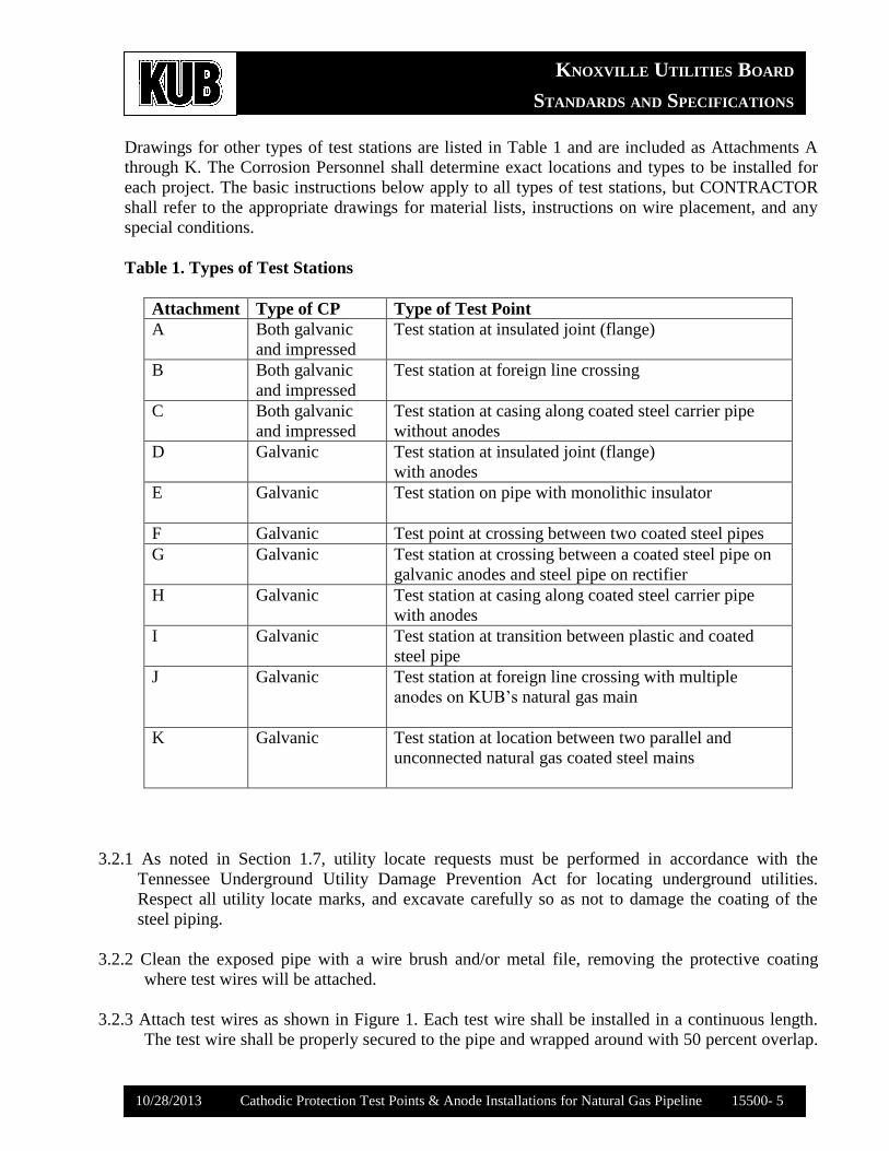
Drawings for other types of test stations are listed in Table 1 and are included as Attachments A
through K. The Corrosion Personnel shall determine exact locations and types to be installed for
each project. The basic instructions below apply to all types of test stations, but CONTRACTOR
shall refer to the appropriate drawings for material lists, instructions on wire placement, and any
special conditions.
Table 1. Types of Test Stations
Attachment Type of CP Type of Test Point
A Both galvanic
and impressed
Test station at insulated joint (flange)
B Both galvanic
and impressed
Test station at foreign line crossing
C Both galvanic
and impressed
Test station at casing along coated steel carrier pipe
without anodes
D Galvanic Test station at insulated joint (flange)
with anodes
E Galvanic Test station on pipe with monolithic insulator
F Galvanic Test point at crossing between two coated steel pipes
G Galvanic Test station at crossing between a coated steel pipe on
galvanic anodes and steel pipe on rectifier
H Galvanic Test station at casing along coated steel carrier pipe
with anodes
I Galvanic Test station at transition between plastic and coated
steel pipe
J Galvanic Test station at foreign line crossing with multiple
anodes on KUB’s natural gas main
K Galvanic Test station at location between two parallel and
unconnected natural gas coated steel mains
3.2.1 As noted in Section 1.7, utility locate requests must be performed in accordance with the
Tennessee Underground Utility Damage Prevention Act for locating underground utilities.
Respect all utility locate marks, and excavate carefully so as not to damage the coating of the
steel piping.
3.2.2 Clean the exposed pipe with a wire brush and/or metal file, removing the protective coating
where test wires will be attached.
3.2.3 Attach test wires as shown in Figure 1. Each test wire shall be installed in a continuous length.
The test wire shall be properly secured to the pipe and wrapped around with 50 percent overlap.
KNOXVILLE UTILITIES BOARD
STANDARDS AND SPECIFICATIONS
10/28/2013 Cathodic Protection Test Points & Anode Installations for Natural Gas Pipeline 15500- 6
Test wires shall be long enough to extend approximately three feet above the test box to prevent
test wires from being unduly stressed or broken during backfilling and future excavation. Each
set of test wires shall be thermite welded carefully to the steel pipe, using fifteen milligrams
(mg) of thermite powder in the mold. When attaching test wires to casings, utilize a pin brazing
process instead.
3.2.4 Reapply coating anywhere the coating was removed and where pipes and wires were welded.
Coating shall be applied according to the manufacturer’s recommendations. The coating
material shall be 2888 RG specialty polymer coating on fusion bonded epoxy pipes and wax
tape on pipes with other kinds of coating (e.g. Yellow jacket, coal tar coating etc).
3.2.5 If instructed by Corrosion Personnel, install a reference electrode following procedures outlined
in Section 3.2 and as shown in Figure 1.
3.2.6 If instructed by Corrosion Engineer, install anodes following procedures outlined in Section 3.4.
3.2.7 Backfill one foot around the coated steel pipe with sand, free from gravel and debris.
3.2.8 Blocks or bricks shall be used to support base of the test box installed, and the test wires shall be
coiled inside the box.
3.2.9 Sand, clean dirt, or other earthen materials may be used to backfill the rest of the excavation to
the ground surface in accordance with Section 02321, Excavation, Bedding, and Backfill for
Utilities.
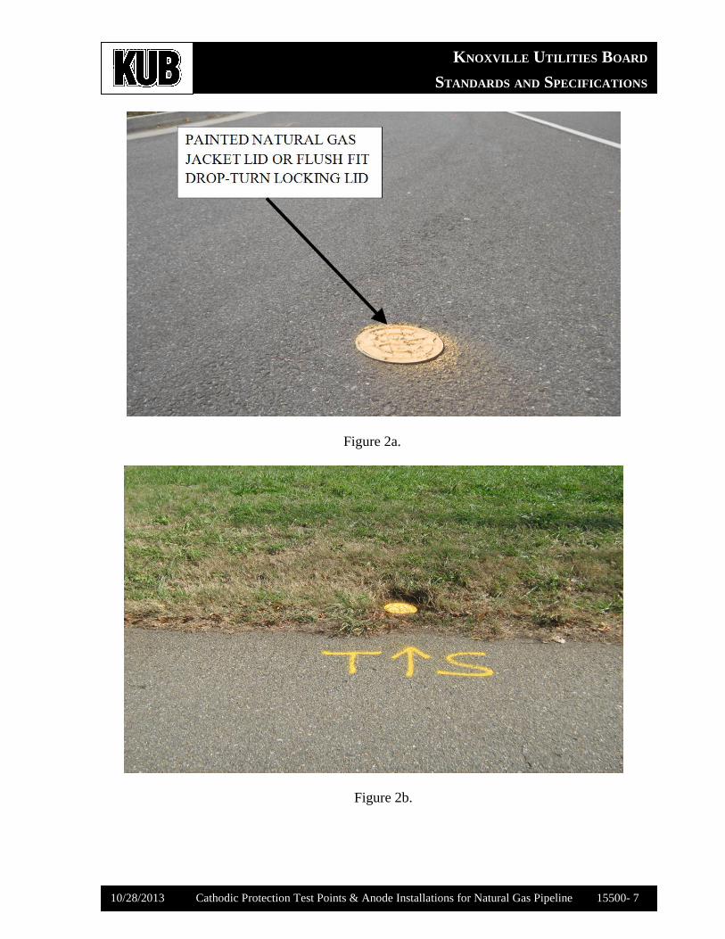
3.2.10 Test stations installed on mains located in pavement including, but not limited to, within a
roadway, sidewalk, or parking area, shall be installed within a KUB-approved natural gas valve
jacket and lid. The lid and jacket shall be flush-mounted to the pavement surface, and the lid
shall be painted with approved yellow paint. See Figure 2 (a-b) for a photograph depicting the
correct installation of the jacket and lid. Light-weight rims can be used for the jackets located
behind the curb, but heavy-duty cast iron rims shall be used for jackets located in roadways.
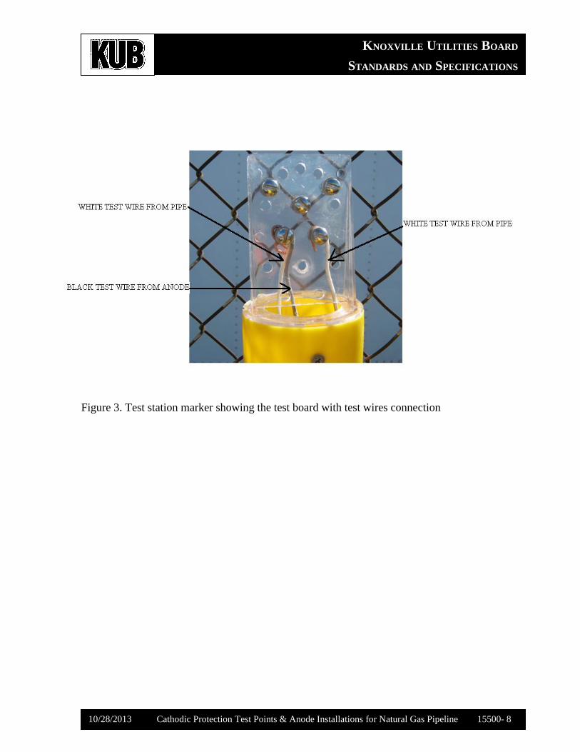
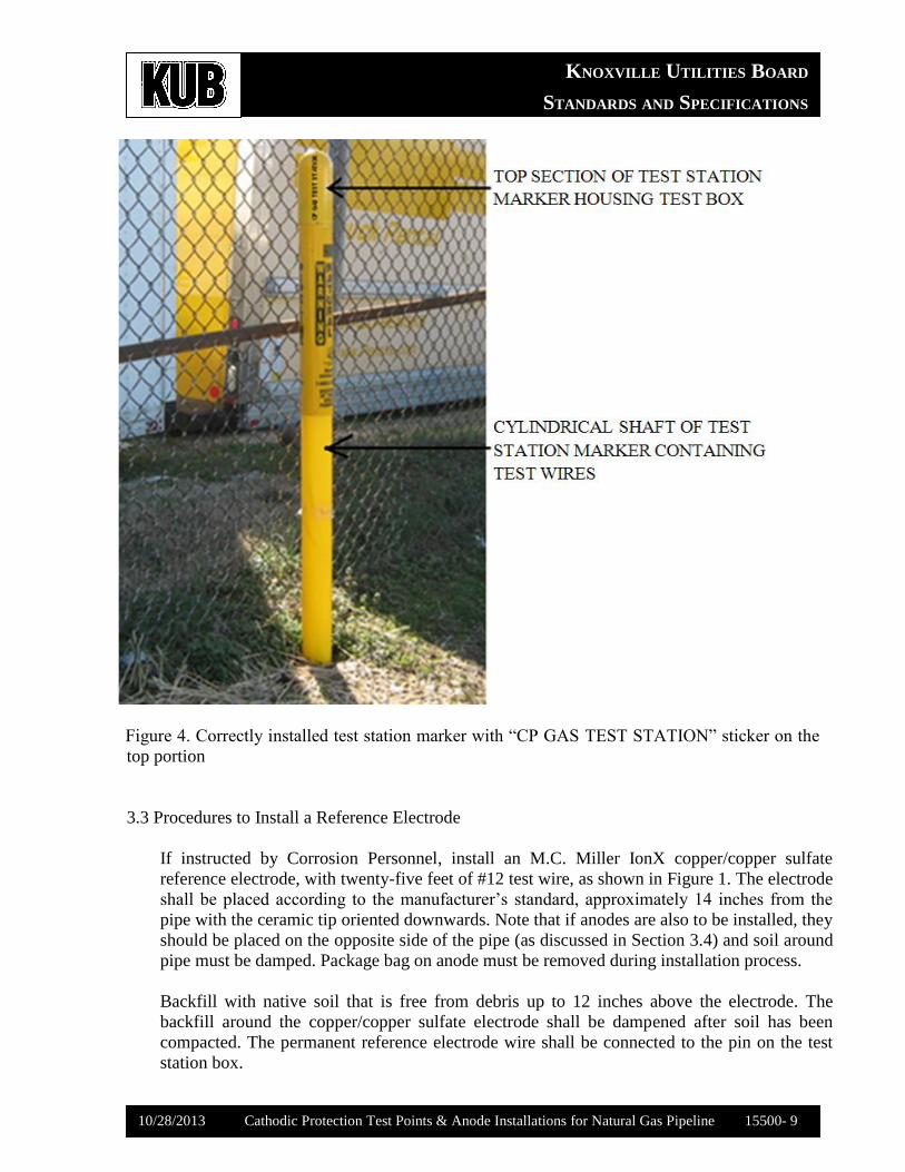
3.2.11 Alternatively, test stations installed in grass or gravel shall be installed inside an approved test
station marker used for marking test points and the pipeline. The marker must protrude at least
36” from the ground surface, although a taller marker may be needed to maintain visibility in
vegetated locations. See Figures 3 and 4 for photographs depicting the correct installation of the
test station marker.
KNOXVILLE UTILITIES BOARD
STANDARDS AND SPECIFICATIONS
10/28/2013 Cathodic Protection Test Points & Anode Installations for Natural Gas Pipeline 15500- 7
Figure 2a.
Figure 2b.
KNOXVILLE UTILITIES BOARD
STANDARDS AND SPECIFICATIONS
10/28/2013 Cathodic Protection Test Points & Anode Installations for Natural Gas Pipeline 15500- 8
Figure 3. Test station marker showing the test board with test wires connection
KNOXVILLE UTILITIES BOARD
STANDARDS AND SPECIFICATIONS
10/28/2013 Cathodic Protection Test Points & Anode Installations for Natural Gas Pipeline 15500- 9
Fi Figure 4. Correctly installed test station marker with “CP GAS TEST STATION” sticker on the
top portion
3.3 Procedures to Install a Reference Electrode
If instructed by Corrosion Personnel, install an M.C. Miller IonX copper/copper sulfate
reference electrode, with twenty-five feet of #12 test wire, as shown in Figure 1. The electrode
shall be placed according to the manufacturer’s standard, approximately 14 inches from the
pipe with the ceramic tip oriented downwards. Note that if anodes are also to be installed, they
should be placed on the opposite side of the pipe (as discussed in Section 3.4) and soil around
pipe must be damped. Package bag on anode must be removed during installation process.
Backfill with native soil that is free from debris up to 12 inches above the electrode. The
backfill around the copper/copper sulfate electrode shall be dampened after soil has been
compacted. The permanent reference electrode wire shall be connected to the pin on the test
station box.
KNOXVILLE UTILITIES BOARD
STANDARDS AND SPECIFICATIONS
10/28/2013 Cathodic Protection Test Points & Anode Installations for Natural Gas Pipeline 15500- 10
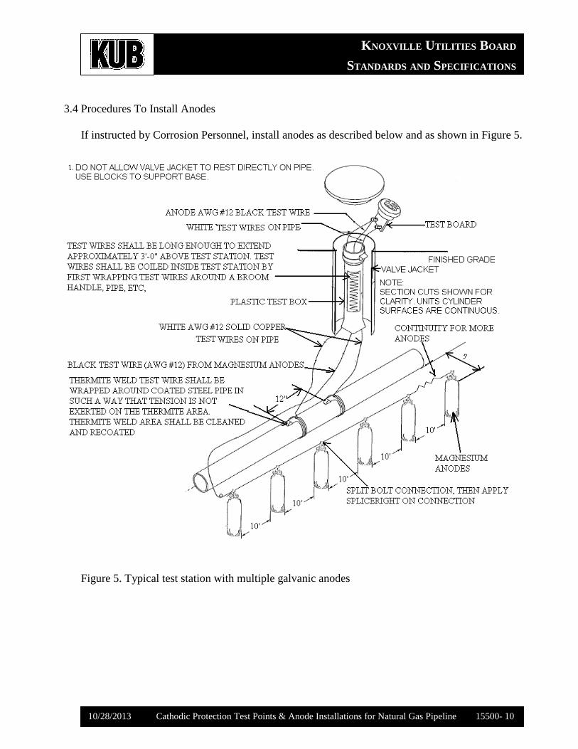
3.4 Procedures To Install Anodes
If instructed by Corrosion Personnel, install anodes as described below and as shown in Figure 5.
Figure 5. Typical test station with multiple galvanic anodes
KNOXVILLE UTILITIES BOARD
STANDARDS AND SPECIFICATIONS
10/28/2013 Cathodic Protection Test Points & Anode Installations for Natural Gas Pipeline 15500- 11
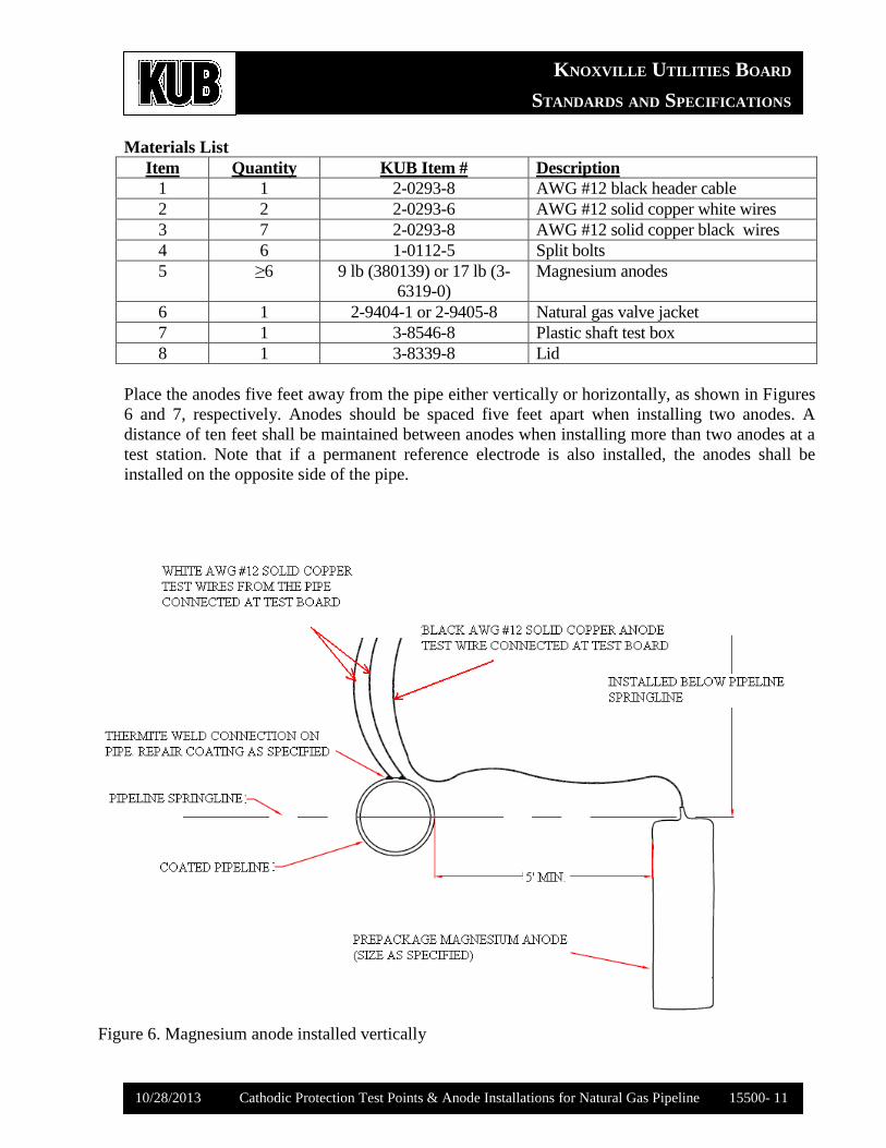
Materials List
Item Quantity KUB Item # Description
1 1 2-0293-8 AWG #12 black header cable
2 2 2-0293-6 AWG #12 solid copper white wires
3 7 2-0293-8 AWG #12 solid copper black wires
4 6 1-0112-5 Split bolts
5 ≥6 9 lb (380139) or 17 lb (3-
6319-0)
Magnesium anodes
6 1 2-9404-1 or 2-9405-8 Natural gas valve jacket
7 1 3-8546-8 Plastic shaft test box
8 1 3-8339-8 Lid
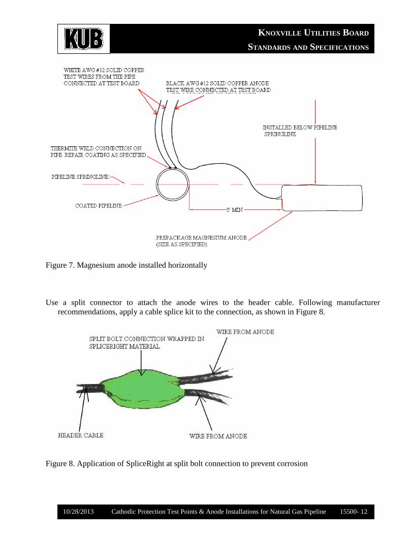
Place the anodes five feet away from the pipe either vertically or horizontally, as shown in Figures
6 and 7, respectively. Anodes should be spaced five feet apart when installing two anodes. A
distance of ten feet shall be maintained between anodes when installing more than two anodes at a
test station. Note that if a permanent reference electrode is also installed, the anodes shall be
installed on the opposite side of the pipe.
Figure 6. Magnesium anode installed vertically
KNOXVILLE UTILITIES BOARD
STANDARDS AND SPECIFICATIONS
10/28/2013 Cathodic Protection Test Points & Anode Installations for Natural Gas Pipeline 15500- 12
Figure 7. Magnesium anode installed horizontally
Use a split connector to attach the anode wires to the header cable. Following manufacturer
recommendations, apply a cable splice kit to the connection, as shown in Figure 8.
Figure 8. Application of SpliceRight at split bolt connection to prevent corrosion
KNOXVILLE UTILITIES BOARD
STANDARDS AND SPECIFICATIONS
10/28/2013 Cathodic Protection Test Points & Anode Installations for Natural Gas Pipeline 15500- 13
The wires from the header cable connecting the anodes shall be attached to the pin on the test
station box. Anodes shall not be connected directly to the pipe.
Soil around the installed anodes shall be dampened to activate the anode. Backfill with native soil,
free from gravel and debris.
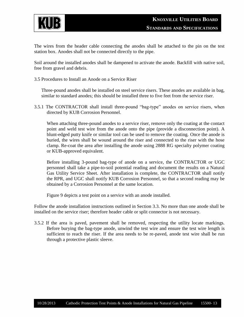
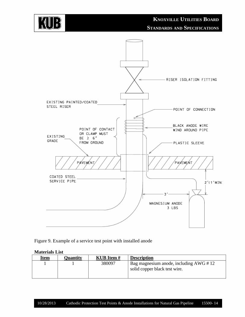
3.5 Procedures to Install an Anode on a Service Riser
Three-pound anodes shall be installed on steel service risers. These anodes are available in bag,
similar to standard anodes; this should be installed three to five feet from the service riser.
3.5.1 The CONTRACTOR shall install three-pound “bag-type” anodes on service risers, when
directed by KUB Corrosion Personnel.
When attaching three-pound anodes to a service riser, remove only the coating at the contact
point and weld test wire from the anode onto the pipe (provide a disconnection point). A
blunt-edged putty knife or similar tool can be used to remove the coating. Once the anode is
buried, the wires shall be wound around the riser and connected to the riser with the hose
clamp. Re-coat the area after installing the anode using 2888 RG specialty polymer coating
or KUB-approved equivalent.
Before installing 3-pound bag-type of anode on a service, the CONTRACTOR or UGC
personnel shall take a pipe-to-soil potential reading and document the results on a Natural
Gas Utility Service Sheet. After installation is complete, the CONTRACTOR shall notify
the RPR, and UGC shall notify KUB Corrosion Personnel, so that a second reading may be
obtained by a Corrosion Personnel at the same location.
Figure 9 depicts a test point on a service with an anode installed.
Follow the anode installation instructions outlined in Section 3.3. No more than one anode shall be
installed on the service riser; therefore header cable or split connector is not necessary.
3.5.2 If the area is paved, pavement shall be removed, respecting the utility locate markings.
Before burying the bag-type anode, unwind the test wire and ensure the test wire length is
sufficient to reach the riser. If the area needs to be re-paved, anode test wire shall be run
through a protective plastic sleeve.
KNOXVILLE UTILITIES BOARD
STANDARDS AND SPECIFICATIONS
10/28/2013 Cathodic Protection Test Points & Anode Installations for Natural Gas Pipeline 15500- 14
Figure 9. Example of a service test point with installed anode
Materials List
Item Quantity KUB Item # Description
1 1 380097 Bag magnesium anode, including AWG # 12
solid copper black test wire.
KNOXVILLE UTILITIES BOARD
STANDARDS AND SPECIFICATIONS
10/28/2013 Cathodic Protection Test Points & Anode Installations for Natural Gas Pipeline 15500- 15
PART 4. RECORDS
A. Records created during installation of CP test points shall be documented neatly, legibly,
and accurately.
B. Once natural gas steel piping has been exposed, complete a Corrosion Observation and a
pipe-to-soil potential reading, documenting the results on a Corrosion Card or Natural Gas
Utility Service Sheet (NGUSS). The completed form shall be given to the OWNER’s
Corrosion Personnel or (RPR).
C. After installation of test stations or anodes on services, contact the RPR. OWNER’s
Corrosion Personnel will conduct tests to make sure that none of the anodes or test wires is
damaged or broken. Corrosion Personnel will also conduct final pipe-to-soil readings.
KNOXVILLE UTILITIES BOARD
STANDARDS AND SPECIFICATIONS
10/28/2013 Cathodic Protection Test Points & Anode Installations for Natural Gas Pipeline 15500- 16
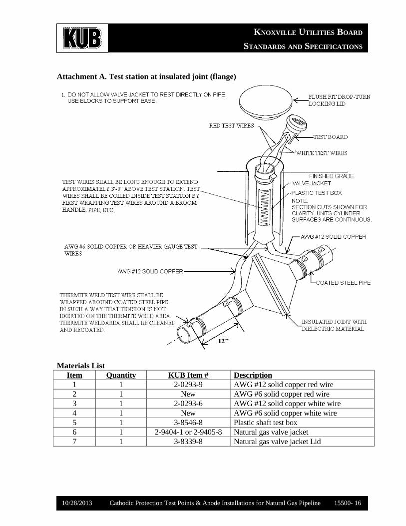
Attachment A. Test station at insulated joint (flange)
Materials List
Item Quantity KUB Item # Description
1 1 2-0293-9 AWG #12 solid copper red wire
2 1 New AWG #6 solid copper red wire
3 1 2-0293-6 AWG #12 solid copper white wire
4 1 New AWG #6 solid copper white wire
5 1 3-8546-8 Plastic shaft test box
6 1 2-9404-1 or 2-9405-8 Natural gas valve jacket
7 1 3-8339-8 Natural gas valve jacket Lid
KNOXVILLE UTILITIES BOARD
STANDARDS AND SPECIFICATIONS
10/28/2013 Cathodic Protection Test Points & Anode Installations for Natural Gas Pipeline 15500- 17
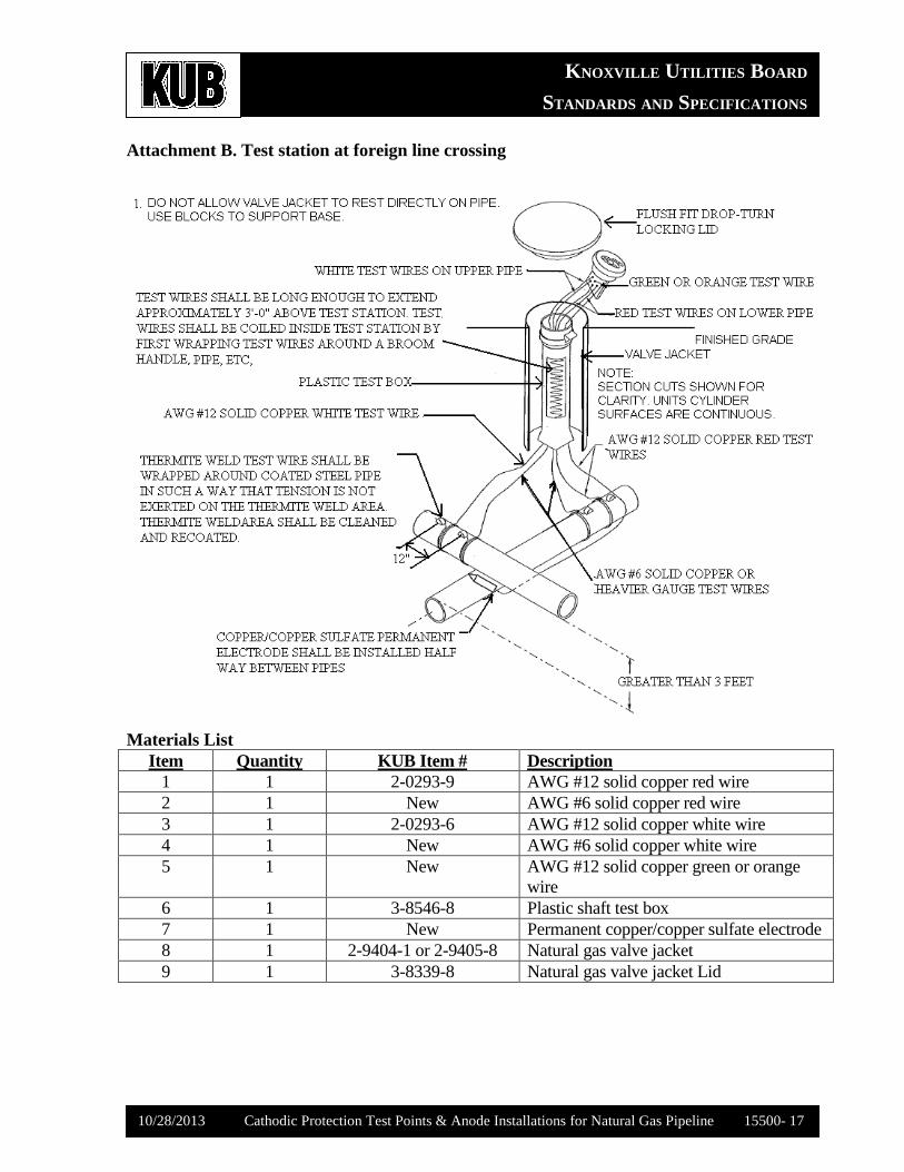
Attachment B. Test station at foreign line crossing
Materials List
Item Quantity KUB Item # Description
1 1 2-0293-9 AWG #12 solid copper red wire
2 1 New AWG #6 solid copper red wire
3 1 2-0293-6 AWG #12 solid copper white wire
4 1 New AWG #6 solid copper white wire
5 1 New AWG #12 solid copper green or orange
wire
6 1 3-8546-8 Plastic shaft test box
7 1 New Permanent copper/copper sulfate electrode
8 1 2-9404-1 or 2-9405-8 Natural gas valve jacket
9 1 3-8339-8 Natural gas valve jacket Lid
KNOXVILLE UTILITIES BOARD
STANDARDS AND SPECIFICATIONS
10/28/2013 Cathodic Protection Test Points & Anode Installations for Natural Gas Pipeline 15500- 18
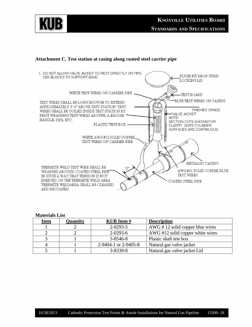
Attachment C. Test station at casing along coated steel carrier pipe
Materials List
Item Quantity KUB Item # Description
1 2 2-0293-5 AWG # 12 solid copper blue wires
2 2 2-0293-6 AWG #12 solid copper white wires
3 1 3-8546-8 Plastic shaft test box
4 1 2-9404-1 or 2-9405-8 Natural gas valve jacket
5 1 3-8339-8 Natural gas valve jacket Lid
KNOXVILLE UTILITIES BOARD
STANDARDS AND SPECIFICATIONS
10/28/2013 Cathodic Protection Test Points & Anode Installations for Natural Gas Pipeline 15500- 19
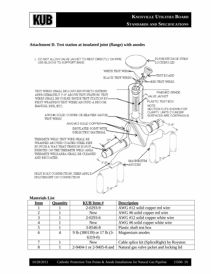
Attachment D. Test station at insulated joint (flange) with anodes
Materials List
Item Quantity KUB Item # Description
1 1 2-0293-9 AWG #12 solid copper red wire
2 1 New AWG #6 solid copper red wire
3 1 2-0293-6 AWG #12 solid copper white wire
4 1 New AWG #6 solid copper white wire
5 1 3-8546-8 Plastic shaft test box
6 4 9 lb (380139) or 17 lb (3-
6319-0)
Magnesium anodes
7 1 New Cable splice kit (SpliceRight) by Royston
8 1 2-9404-1 or 2-9405-8 and Natural gas valve jacket and locking lid
KNOXVILLE UTILITIES BOARD
STANDARDS AND SPECIFICATIONS
10/28/2013 Cathodic Protection Test Points & Anode Installations for Natural Gas Pipeline 15500- 20
3-8339-8
9 2 1-0112-5 Split bolts
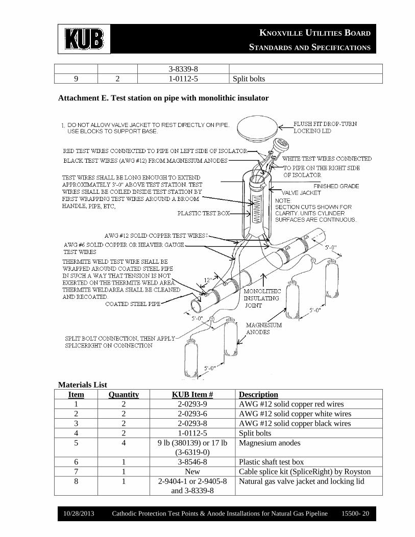
Attachment E. Test station on pipe with monolithic insulator
Materials List
Item Quantity KUB Item # Description
1 2 2-0293-9 AWG #12 solid copper red wires
2 2 2-0293-6 AWG #12 solid copper white wires
3 2 2-0293-8 AWG #12 solid copper black wires
4 2 1-0112-5 Split bolts
5 4 9 lb (380139) or 17 lb
(3-6319-0)
Magnesium anodes
6 1 3-8546-8 Plastic shaft test box
7 1 New Cable splice kit (SpliceRight) by Royston
8 1 2-9404-1 or 2-9405-8
and 3-8339-8
Natural gas valve jacket and locking lid
KNOXVILLE UTILITIES BOARD
STANDARDS AND SPECIFICATIONS
10/28/2013 Cathodic Protection Test Points & Anode Installations for Natural Gas Pipeline 15500- 21
9 2 1-0112-5 Split bolts
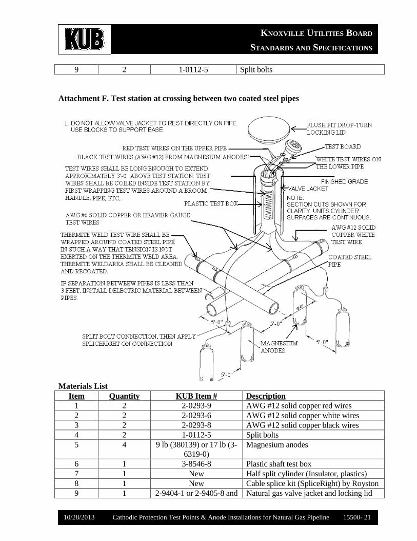
Attachment F. Test station at crossing between two coated steel pipes
Materials List
Item Quantity KUB Item # Description
1 2 2-0293-9 AWG #12 solid copper red wires
2 2 2-0293-6 AWG #12 solid copper white wires
3 2 2-0293-8 AWG #12 solid copper black wires
4 2 1-0112-5 Split bolts
5 4 9 lb (380139) or 17 lb (3-
6319-0)
Magnesium anodes
6 1 3-8546-8 Plastic shaft test box
7 1 New Half split cylinder (Insulator, plastics)
8 1 New Cable splice kit (SpliceRight) by Royston
9 1 2-9404-1 or 2-9405-8 and Natural gas valve jacket and locking lid
KNOXVILLE UTILITIES BOARD
STANDARDS AND SPECIFICATIONS
10/28/2013 Cathodic Protection Test Points & Anode Installations for Natural Gas Pipeline 15500- 22
3-8339-8
10 2 1-0112-5 Split bolts
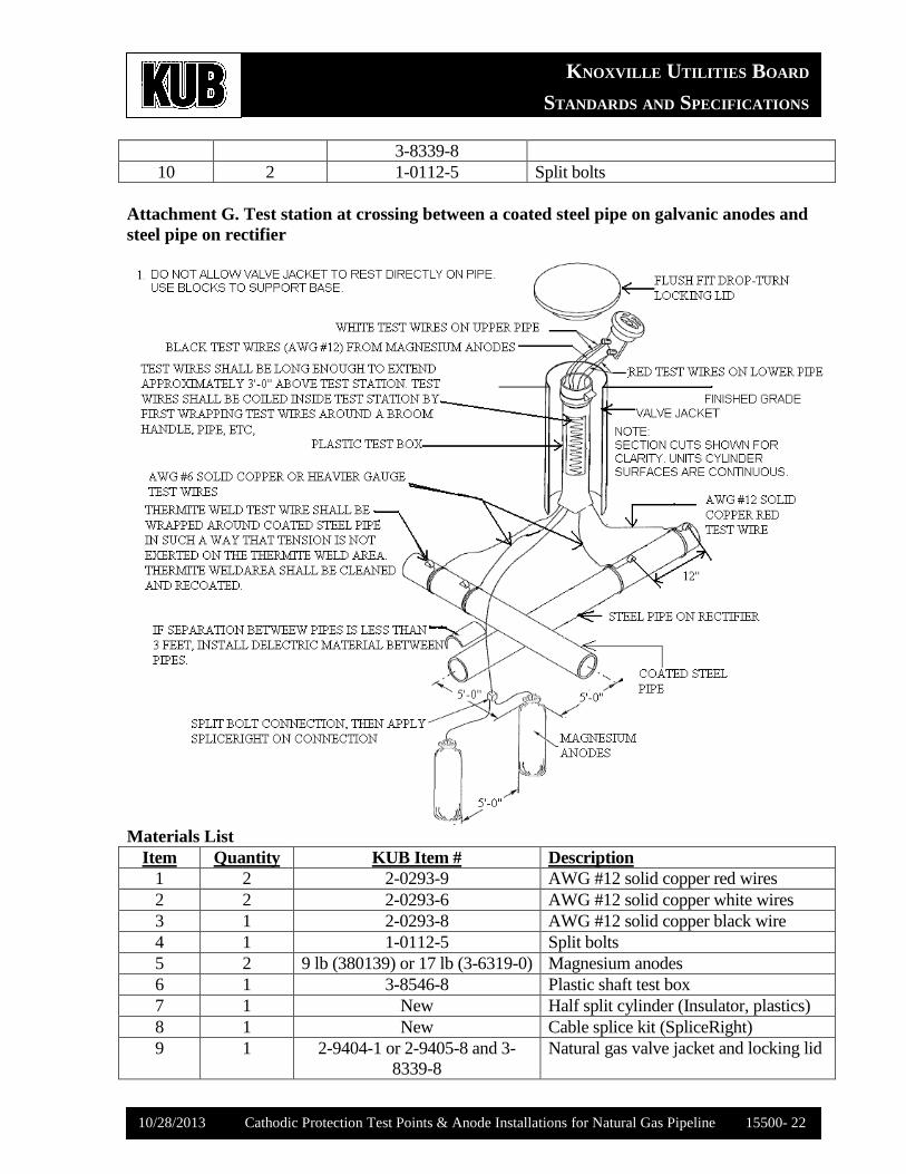
Attachment G. Test station at crossing between a coated steel pipe on galvanic anodes and
steel pipe on rectifier
Materials List
Item Quantity KUB Item # Description
1 2 2-0293-9 AWG #12 solid copper red wires
2 2 2-0293-6 AWG #12 solid copper white wires
3 1 2-0293-8 AWG #12 solid copper black wire
4 1 1-0112-5 Split bolts
5 2 9 lb (380139) or 17 lb (3-6319-0) Magnesium anodes
6 1 3-8546-8 Plastic shaft test box
7 1 New Half split cylinder (Insulator, plastics)
8 1 New Cable splice kit (SpliceRight)
9 1 2-9404-1 or 2-9405-8 and 3-
8339-8
Natural gas valve jacket and locking lid
KNOXVILLE UTILITIES BOARD
STANDARDS AND SPECIFICATIONS
10/28/2013 Cathodic Protection Test Points & Anode Installations for Natural Gas Pipeline 15500- 23
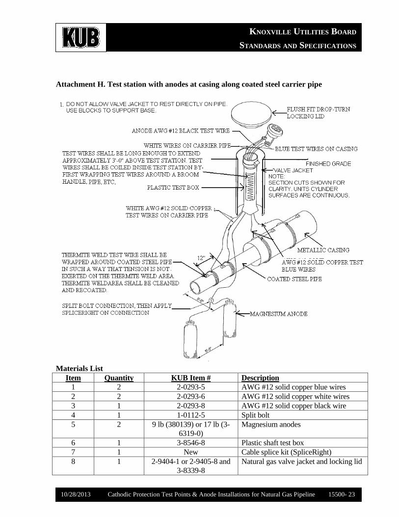
Attachment H. Test station with anodes at casing along coated steel carrier pipe
Materials List
Item Quantity KUB Item # Description
1 2 2-0293-5 AWG #12 solid copper blue wires
2 2 2-0293-6 AWG #12 solid copper white wires
3 1 2-0293-8 AWG #12 solid copper black wire
4 1 1-0112-5 Split bolt
5 2 9 lb (380139) or 17 lb (3-
6319-0)
Magnesium anodes
6 1 3-8546-8 Plastic shaft test box
7 1 New Cable splice kit (SpliceRight)
8 1 2-9404-1 or 2-9405-8 and
3-8339-8
Natural gas valve jacket and locking lid
KNOXVILLE UTILITIES BOARD
STANDARDS AND SPECIFICATIONS
10/28/2013 Cathodic Protection Test Points & Anode Installations for Natural Gas Pipeline 15500- 24
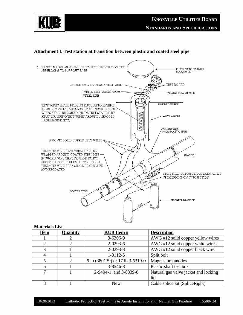
Attachment I. Test station at transition between plastic and coated steel pipe
Materials List
Item Quantity KUB Item # Description
1 2 3-6306-9 AWG #12 solid copper yellow wires
2 2 2-0293-6 AWG #12 solid copper white wires
3 1 2-0293-8 AWG #12 solid copper black wire
4 1 1-0112-5 Split bolt
5 2 9 lb (380139) or 17 lb 3-6319-0 Magnesium anodes
6 1 3-8546-8 Plastic shaft test box
7 1 2-9404-1 and 3-8339-8 Natural gas valve jacket and locking
lid
8 1 New Cable splice kit (SpliceRight)
KNOXVILLE UTILITIES BOARD
STANDARDS AND SPECIFICATIONS
10/28/2013 Cathodic Protection Test Points & Anode Installations for Natural Gas Pipeline 15500- 25
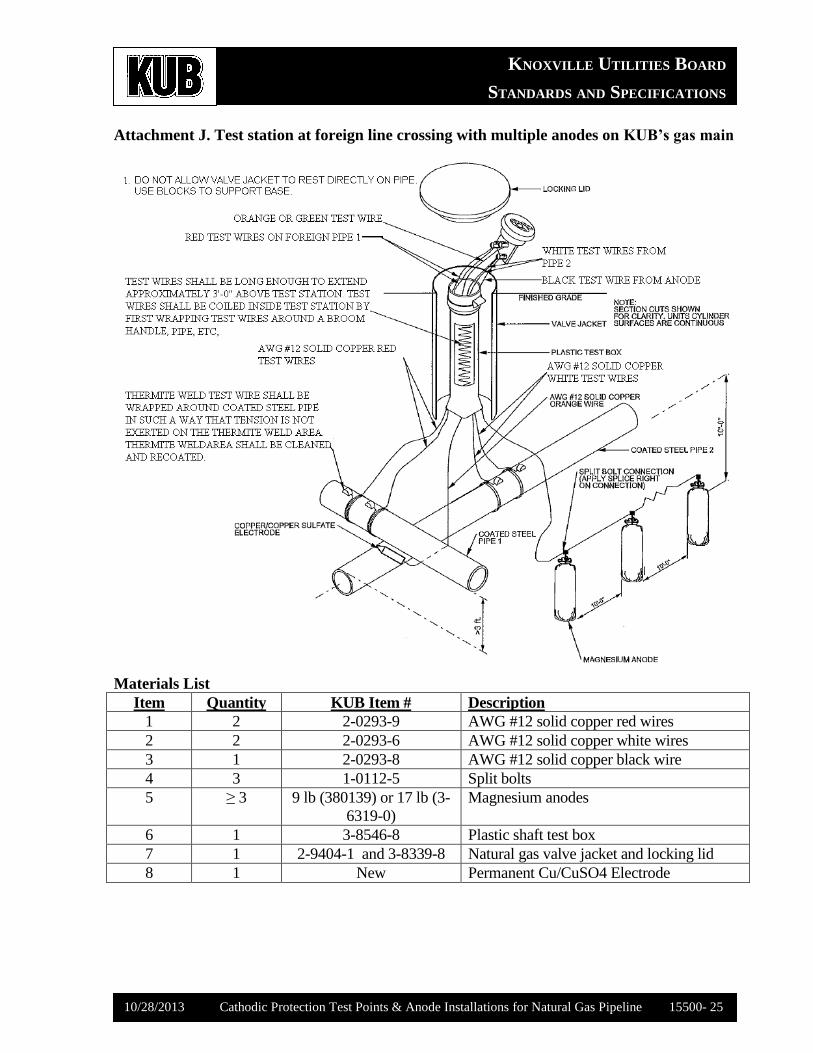
Attachment J. Test station at foreign line crossing with multiple anodes on KUB’s gas main
Materials List
Item Quantity KUB Item # Description
1 2 2-0293-9 AWG #12 solid copper red wires
2 2 2-0293-6 AWG #12 solid copper white wires
3 1 2-0293-8 AWG #12 solid copper black wire
4 3 1-0112-5 Split bolts
5 ≥ 3 9 lb (380139) or 17 lb (3-
6319-0)
Magnesium anodes
6 1 3-8546-8 Plastic shaft test box
7 1 2-9404-1 and 3-8339-8 Natural gas valve jacket and locking lid
8 1 New Permanent Cu/CuSO4 Electrode
KNOXVILLE UTILITIES BOARD
STANDARDS AND SPECIFICATIONS
10/28/2013 Cathodic Protection Test Points & Anode Installations for Natural Gas Pipeline 15500- 26
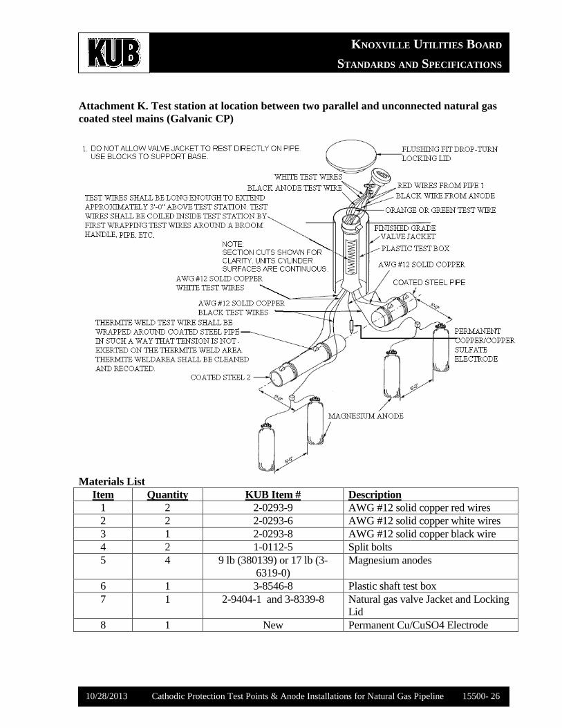
Attachment K. Test station at location between two parallel and unconnected natural gas
coated steel mains (Galvanic CP)
Materials List
Item Quantity KUB Item # Description
1 2 2-0293-9 AWG #12 solid copper red wires
2 2 2-0293-6 AWG #12 solid copper white wires
3 1 2-0293-8 AWG #12 solid copper black wire
4 2 1-0112-5 Split bolts
5 4 9 lb (380139) or 17 lb (3-
6319-0)
Magnesium anodes
6 1 3-8546-8 Plastic shaft test box
7 1 2-9404-1 and 3-8339-8 Natural gas valve Jacket and Locking
Lid
8 1 New Permanent Cu/CuSO4 Electrode