Embed Size (px)
Citation preview
GUIDELINES HAS/PDC/Design Division Project Title Houston, Texas Proj./CIP No.
(These Guidelines are basic minimum criteria to be met in preparing the final specifications for this
section, which is the responsibility of the Designer/Contractor/Installation Team.)
IDENTIFICATION AND LABELING OF COMMUNICATION INFRASTRUCTURE
270553 - 1 REV. 01-31-2020
SECTION 270553
IDENTIFICATION AND LABELING OF COMMUNICATION INFRASTRUCTURE (REV. 01-31-2020-BW)
1 INTRODUCTION 1.1 General 1.1.1 As the Houston Airport System (HAS) continues to develop both its private and commercial inter-ests, it is essential that an effective telecommunications infrastructure be developed and maintained to ensure the support of any and all services which rely on the electronic transport of information. To effec-tively administer these assets requires a disciplined effort that begins with a systematic practice and pro-cedure for capturing useful data regarding inventories that might be conducted at any point during the lifecycle of a project. 1.2 Objective 1.2.1 The objective and intent of this standard is to provide uniform GIS inventory and documentation practices/guidelines for any person or party directly involved with data collection, administration and/or accountability of the HAS IT telecommunications infrastructure or related systems.
1.3 Intended Use 1.3.1 Any designer, consultant or engineering entity contracting with the Houston Airport System to
inventory/document the telecommunications physical and network configurations will need to re-fer to this document for clarification regarding standard operating procedures. The guidelines giv-en here provide for effective documentation of the HAS telecommunications network. The result of following this standard will be a telecommunications infrastructure that is well documented and easily managed by the administrator.
Note: For specific criteria concerning GIS/GPS datum, refer to the OASIS Standards document main-
tained by direction under the HAS Planning Design and Construction department. Said datum is not spe-cific to the Information Technology department and thus will not be replicated here.
1.4 Life of the Standard 1.4.1 This standard is a living document. The criteria contained in this standard are subject to revision without notice, as warranted by advances in administration techniques related to telecommunications technology. 1.4.2 This manual is the property of the Houston Airport System. The contents of this manual are proprie-tary and should not be copied or disclosed without prior written permission of the Houston Airport System. Any variation from the standards in this manual should be addressed by the Houston Airport System IT GIS contact listed below for approval prior to implementation on a project.

GUIDELINES HAS/PDC/Design Division Project Title Houston, Texas Proj./CIP No.
(These Guidelines are basic minimum criteria to be met in preparing the final specifications for this
section, which is the responsibility of the Designer/Contractor/Installation Team.)
IDENTIFICATION AND LABELING OF COMMUNICATION INFRASTRUCTURE
270553 - 2 REV. 01-31-2020
Brandon Williams Jay Kabouni Li Sun IT Project Manager Systems Consultant Senior GIS Analyst Technology Infrastructure Technology Infrastructure Technology Infrastructure Houston Airport System Houston Airport System Houston Airport System 281-233-1394 281-233-1660 281-233-1169 [email protected] [email protected] [email protected]
2 GENERAL 2.1 Scope 2.1.1 This standard specifies the GIS inventory and documentation requirements for the Houston Airport System IT Telecommunications Infrastructure, Network Engineer and associated information databases. Areas of the infrastructure and/or databases to be inventoried, administered, monitored or maintained include:
a) terminations for the telecommunications media located in work areas, telecommunications closets, equipment rooms, and entrance facilities;
b) equipment/devices hosting physical terminations;
c) telecommunications media (cable) between terminations; d) pathways (spans) between terminations that contain the media; e) spaces (structures) where terminations are located;
f) bonding/grounding as it applies to telecommunications; g) geophysical plant networks i.e., manhole, handhole, pullbox, cabinet, pedestal, building access
points;
h) splice enclosures. NOTE: Whereas this document provides an outline and overview of the GIS documentation process, the following Telecommunications Infrastructure Specifications for the Houston Airport System should be referenced for detailed administrative requirements:
GUIDELINES HAS/PDC/Design Division Project Title Houston, Texas Proj./CIP No.
(These Guidelines are basic minimum criteria to be met in preparing the final specifications for this
section, which is the responsibility of the Designer/Contractor/Installation Team.)
IDENTIFICATION AND LABELING OF COMMUNICATION INFRASTRUCTURE
270553 - 3 REV. 01-31-2020
2.1.2 This standard also specifies requirements for the collection, organization, and presentation of as-built data. 2.1.3 In addition to providing requirements and guidelines for a traditional paper-based documentation
system, this standard will serve as the reference for all associated computer-based administration tools.
Contracting parties, by this standard, are required to attend an HAS-IT coordination meeting prior to commencement of any documentation effort; the scope of work and project expectations will be dis-
cussed at length. You will be given additional direction as required and any useful maps, diagrams, nu-merical sequences, etc. will be provided to you at this time.
3. REFERENCES
The latest published version at the date of contract applies to all references. Related Documents include
all Drawings and General Provisions of the Contract. In Conflict between contract documents, the most
stringent will be applied.
Related Specifications: Use these Specifications for all related work not specifically covered in this speci-
fication.
1. Section 270526: Telecommunication Grounding and Bonding 2. Section 270528: Interior Communication Pathways 3. Section 270543: Exterior Communication Pathways 4. Section 270553: Identification and Labeling of Communication Infrastructure 5. Section 271100: Communication Cabinets and Equipment Rooms 6. Section 271300: Backbone and Riser Media Infrastructure 7. Section 271500: Horizontal Media Infrastructure 8. Section 272100: Data Communication Network Equipment 9. Section 272200: PC, Laptop, Servers and Equipment 10. Section 275113: Audio Communication System 11. Section 281300: Access Control System 12. Section 232313: Video Surveillance Control and Management System
4. DEFINITIONS 4.1 General 3.1.1 This section contains definitions of terms, acronyms, abbreviations, and formats that have special technical meaning or that are unique to the technical content of this standard. 4.2 Definitions
GUIDELINES HAS/PDC/Design Division Project Title Houston, Texas Proj./CIP No.
(These Guidelines are basic minimum criteria to be met in preparing the final specifications for this
section, which is the responsibility of the Designer/Contractor/Installation Team.)
IDENTIFICATION AND LABELING OF COMMUNICATION INFRASTRUCTURE
270553 - 4 REV. 01-31-2020
4.2.1 For the purposes of this standard, the following definitions apply: assignment A unique designation assigned to a person who is expected to use the circuit, equipment, service, etc., serving a particular work area. Examples of an assignment: telephone number, a name, a circuit number or a logical address. backbone Network of copper and fiber connections between termination panels/switches. cable An assembly of one or more copper conductors or optical fibers within an enveloping sheath, constructed so as to permit use of the conductors singly or in groups. campus The buildings and grounds have legal contiguous interconnection. (TIA) equipment Generally, an endpoint for cable lengths; any hardware device/component. Used to terminate cable for cross-connection or interconnection to other cables or devices. grounding electrode conductor The conductor used to connect the grounding electrode to the equipment grounding conductor and/or to the grounded conductor of the circuit at the service equipment or at the source of a separately derived system. handhole (HH)
A structure similar to a small maintenance hole in which cable can be pulled, but not large enough for a person to fully enter to perform work.
identifier An item of information that links a specific element of the telecommunications infrastructure with its corresponding record. (TIA) linkage A connection between a record and an identifier or between records.(TIA) location A position occupied or available for occupancy within a site or infrastructure network. manhole (MH)
A vault located in the ground or earth as part of an underground duct system and used to facilitate placing, establishing connections and maintenance of cables as well as placing associated equip-ment, in which it is expected that a person will enter to perform work. (TIA).
outlet box (telecommunications)
A metallic or nonmetallic box mounted within a floor, wall or ceiling and used to hold telecommunications outlet/connectors or transition device. (TIA)

GUIDELINES HAS/PDC/Design Division Project Title Houston, Texas Proj./CIP No.
(These Guidelines are basic minimum criteria to be met in preparing the final specifications for this
section, which is the responsibility of the Designer/Contractor/Installation Team.)
IDENTIFICATION AND LABELING OF COMMUNICATION INFRASTRUCTURE
270553 - 5 REV. 01-31-2020
outlet / connector (telecommunications) A connecting device in the work area on which horizontal cable or outlet cables terminates. (TIA) pathways A raceway, conduit, sleeve, or exposed location, for the placing of telecommunications cable that links telecommunications spaces together. record
The permanent documentation of installed telecommunications infrastructure obtained from as-builts.
record drawing (as-built)
The documentation of measurements, location, and quantities of material work performed. May be in the form of marked up documents or other work order forms.
report A presentation of a collection of information from various records. site Spatial location of an actual or planned structure or set of structures. span A raceway, conduit, sleeve, or exposed location, for the placing of telecommunications cable that links telecommunications spaces together. splice A joining of conductors meant to be permanent. (TIA) splice box A box, located in a pathway run, intended to house a cable splice.(TIA) splice enclosure A device used to protect a cable or wire splice.(TIA) structure Generally an endpoint for span lengths; i.e., manhole, handhole, cabinet, junction box, pedestal, building access point, communications rooms, work areas. structure unit A component of the structure; usually housing equipment i.e., cabinet, rack. telecommunications Any transmission, emission, or reception of signs, signals, writings, images, and sounds; that is, information of any nature by cable, radio, optical or other electromagnetic systems. (TIA) telecommunications infrastructure The components (telecommunications spaces, cable pathways, grounding, wiring and termination hardware) that together provide the basic support for the distribution of all

GUIDELINES HAS/PDC/Design Division Project Title Houston, Texas Proj./CIP No.
(These Guidelines are basic minimum criteria to be met in preparing the final specifications for this
section, which is the responsibility of the Designer/Contractor/Installation Team.)
IDENTIFICATION AND LABELING OF COMMUNICATION INFRASTRUCTURE
270553 - 6 REV. 01-31-2020
telecommunications information. telecommunications media Wire, cable, or conductor used for telecommunications. telecommunications space Areas used for the installation and termination of telecommunications equipment and cable, e.g., telecommunications closets, work areas, false ceilings, and manholes/handholes. termination position A discrete element of termination hardware where telecommunications conductors are terminated. work area; work station A building space where the occupants interact with telecommunications equipment.(TIA)
5 DOCUMENTATION CONCEPTS 5.1 General 5.1.1 This section describes the concepts of identifiers, records, linkages among records, and presenta-tion of information necessary to administer infrastructure cable, spans and structures. 5.2 Identifiers 5.2.1 An identifier is assigned to an element of the telecommunications infrastructure to link it to its cor-responding record. Identifiers shall be marked at the elements to be administered. 5.2.2 Identifiers used to access record sets of the same type shall be unique. For example, each identifi-er for each one of the set of cable records shall be unique. Unique identifiers across all types of telecom-munications records are mandatory. For example, no cable record identifier should be identical to any pathway record identifier. 5.2.3 Labeling is the marking of an element of the telecommunications infrastructure with an identifier and (optionally) other relevant information. Labeling shall be accomplished in either of two ways: separate labels may be securely affixed to the element to be administered, or the element itself may be marked. 5.3 Records 5.3.1 A record is a collection of information about or related to a specific element of the telecommunica-tions infrastructure. 5.3.2 Elements identified as required information and required linkages shall constitute the minimum re-quirements for these records. Specific information and other linkages suggest additional elements that may be useful to the administrative system, such as cable length.

GUIDELINES HAS/PDC/Design Division Project Title Houston, Texas Proj./CIP No.
(These Guidelines are basic minimum criteria to be met in preparing the final specifications for this
section, which is the responsibility of the Designer/Contractor/Installation Team.)
IDENTIFICATION AND LABELING OF COMMUNICATION INFRASTRUCTURE
270553 - 7 REV. 01-31-2020
5.3.3 Telecommunications records are typically used in conjunction with other records. For example, a user record or assignment may contain an identifier to the record of the cable that serves an individual’s workspace. Conversely, a cable record may also contain an identifier for a user record or assignment. 5.3.4 By this standard, the Houston Airport System utilizes AutoCAD and ArcGIS as the software plat-forms by which all telecommunications infrastructure records and linkages are recorded and maintained. 5.4 Relationships 4.4.1 Relationships are the logical connections between identifiers and records. The records for infra-structure elements shall be interlinked. For example, in a cable record, termination port identifiers point to specific termination port records that contain additional information about each of the cable termination ports. 5.5 Assignment 5.5.1 An “assignment” is a specific term of reference that allows the association of the end location, cable pairing record or termination port record with additional information. For example, an assignment such as a telephone number or circuit number can associate a user with elements of the telecommunications in-frastructure. This aids in troubleshooting by identifying both the physical and logical connectivity from a single circuit assignment. 5.6 Presentation of Information 5.6.1 A typical documentation system includes labels, records, reports, drawings, and work orders. Re-ports compile and present information found in the records. Graphical information regarding the relation-ship of the telecommunications infrastructure to other infrastructures within the campus or site is present-ed in drawing format. Work orders document the operations needed to implement changes affecting the telecommunications infrastructure. 5.6.2 Reports present information selected from the various telecommunications infrastructure records. Reports may be generated from a single set of records or from several sets of interlinked records. 5.6.3 Drawings are used to illustrate different stages of telecommunications infrastructure planning and development. Generally, conceptual and installation drawings supply input to the record drawings that graphically document the telecommunications infrastructure. These record drawings as well as some equipment schedules and installation drawings (i.e., rack layouts) become part of the administration sys-tem documentation. 5.6.4 Conceptual drawings (i.e., one-line or riser diagrams) are used to illustrate the proposed design intent. They do not typically include all telecommunications infrastructure elements or identifiers and do not necessarily become part of the administration documentation. 5.6.5 Installation or bid drawings are used to document (graphically) the telecommunications infrastruc-ture to be installed. They should illustrate relevant infrastructure elements and may also describe the means of installation. Identifiers may or may not be included on the drawings.
GUIDELINES HAS/PDC/Design Division Project Title Houston, Texas Proj./CIP No.
(These Guidelines are basic minimum criteria to be met in preparing the final specifications for this
section, which is the responsibility of the Designer/Contractor/Installation Team.)
IDENTIFICATION AND LABELING OF COMMUNICATION INFRASTRUCTURE
270553 - 8 REV. 01-31-2020
5.6.6 Record drawings (as-builts) graphically document the installed telecommunications infrastructure through floor plans, elevation, and detail drawings. These drawings may differ from installation drawings because of changes and specific site conditions. Key elements of the telecommunications infrastructure shall have identifiers assigned. The span/structure and wiring portions of the infrastructure each may have separate drawings if warranted by the complexity of the installation or the scale of the drawings. 5.6.7 ESRI (ArcGIS) formatted feature class and feature class layers graphically depict data in a spatial environment and are linked via physical relationship protocols established by the administrator through the utilization of software engineered towards GIS applications. 5.7 Work Orders (Symantec) 5.7.1 Work orders document the actions needed to implement changes affecting the telecommunications infrastructure as it was actually installed. The changes may involve several telecommunications compo-nents as well as other related systems. The Documentation Team utilizes Symantec software as its change-management notification platform. Typical Symantec tickets document actions such as moving a patch cord, installing a conduit, cross-connect or relocating an outlet box. A Symantec ticket may involve structures, spans, cable, splices, terminations, or grounding, either individually or in combination. A Sy-mantec ticket should list both the personnel responsible for the physical action and those responsible for updating various portions of the documentation to assure its accuracy. Prior to commencement of an ac-tion that would result in a change to any telecommunications infrastructure component or related system; a Symantec ticket should be submitted in accordance with departmental and operational requirements. 5.8 Summary 5.8.1 This section has presented basic concepts of documentation for the Houston Airport System Tele-communications Infrastructure. The sections that follow specify the administration of each of the compo-nents of the infrastructure in greater detail.
6 HAS IT INFRASTRUCTURE STANDARDS FOR DOCUMENTATION 6.1 Data Collection and Administration Concepts 6.1.1 This section describes the documentation of assets within the administrative jurisdiction of the Houston Airport System - Public Safety and Information Technology department. As changes are made to the assets, affected labels, records, reports and drawings shall be updated or revised. The following outline assumes that the contracting parties understand the GIS/GPS datum specifications and requirements as provided in the OASIS standards. Further, that the equipment to be used towards
gathering the data has been configured accordingly. 6.2 STRUCTURES
GUIDELINES HAS/PDC/Design Division Project Title Houston, Texas Proj./CIP No.
(These Guidelines are basic minimum criteria to be met in preparing the final specifications for this
section, which is the responsibility of the Designer/Contractor/Installation Team.)
IDENTIFICATION AND LABELING OF COMMUNICATION INFRASTRUCTURE
270553 - 9 REV. 01-31-2020
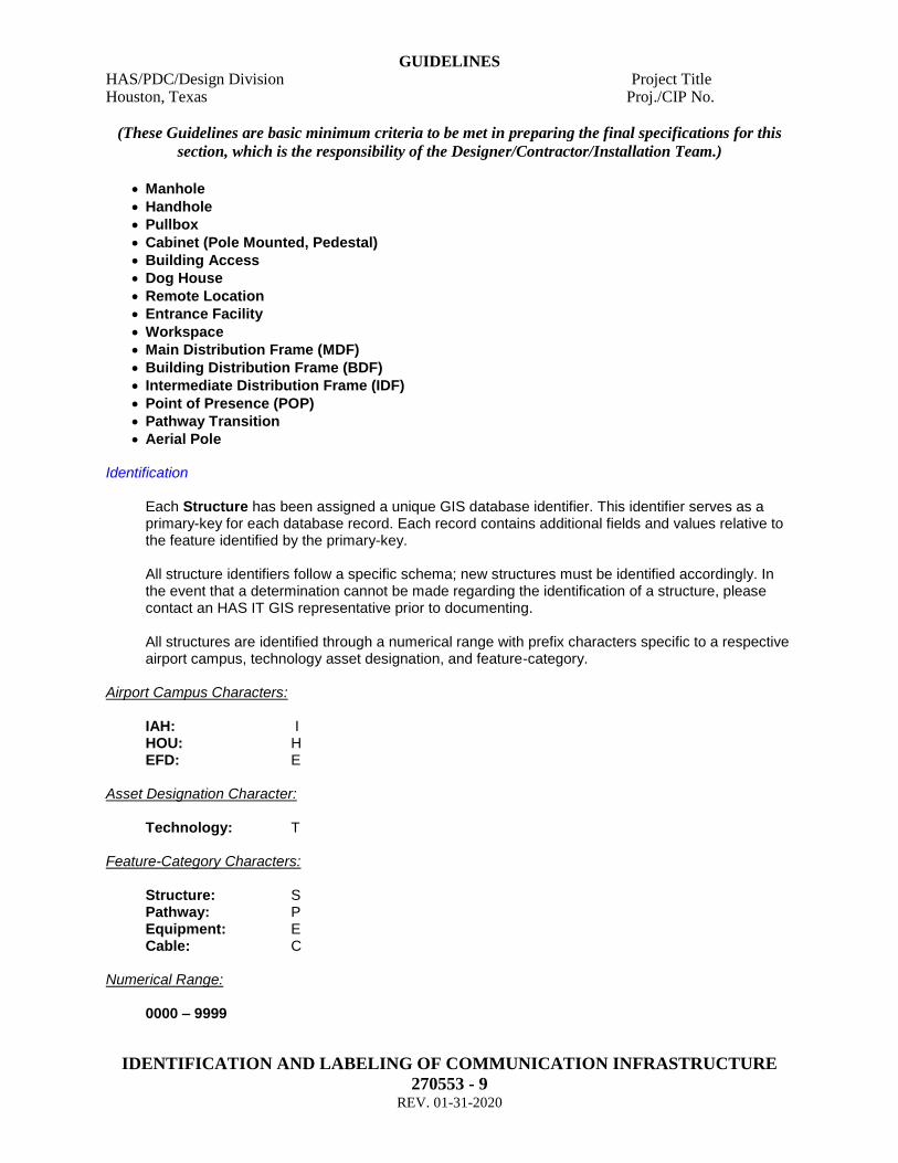
• Manhole
• Handhole
• Pullbox
• Cabinet (Pole Mounted, Pedestal)
• Building Access
• Dog House
• Remote Location
• Entrance Facility
• Workspace
• Main Distribution Frame (MDF)
• Building Distribution Frame (BDF)
• Intermediate Distribution Frame (IDF)
• Point of Presence (POP)
• Pathway Transition
• Aerial Pole Identification
Each Structure has been assigned a unique GIS database identifier. This identifier serves as a primary-key for each database record. Each record contains additional fields and values relative to the feature identified by the primary-key. All structure identifiers follow a specific schema; new structures must be identified accordingly. In the event that a determination cannot be made regarding the identification of a structure, please contact an HAS IT GIS representative prior to documenting. All structures are identified through a numerical range with prefix characters specific to a respective airport campus, technology asset designation, and feature-category.
Airport Campus Characters:
IAH: I HOU: H EFD: E
Asset Designation Character:
Technology: T Feature-Category Characters:
Structure: S Pathway: P Equipment: E Cable: C
Numerical Range:
0000 – 9999

GUIDELINES HAS/PDC/Design Division Project Title Houston, Texas Proj./CIP No.
(These Guidelines are basic minimum criteria to be met in preparing the final specifications for this
section, which is the responsibility of the Designer/Contractor/Installation Team.)
IDENTIFICATION AND LABELING OF COMMUNICATION INFRASTRUCTURE
270553 - 10 REV. 01-31-2020
Example: ITS0054 (IAH Structure), HTS0054 (HOU Structure), ETS0054 (EFD Structure) Manhole Numerical Range: Note: When planning to identify newly constructed or newly placed HAS assets, the contractor is ex-pected to coordinate with the HAS IT GIS staff prior to labeling. This action will account for all identifiers previously assigned and prevent duplications or omissions. Labeling
Labeling should follow the identification schema and further be accomplished via an approved method described below. Newly constructed structures (manhole, handhole, pullbox, cabinet) will require that their identifiers be etched onto the lid or affixed with an appropriate label material. Manholes and handholes should be stamped on the lid itself, as well as the metal ring/material surrounding the opening; or the con-crete foundation (topside). Utilize an appropriate chisel or stamp, or labeling device to accomplish the task. The Technology Infrastructure group does not maintain the specification for labeling newly con-structed structures (dog house, remote location, entrance facility, workspace, MDF, BDF, IDF, POP, Pole). These should be placarded according to current HAS Infrastructure specification. The Technology Infrastructure GIS identifiers (described in the previous paragraphs) relevant to these spaces and locations are preserved for GIS database record keeping purposes only. Contact an HAS Infrastructure representative for clarification on physical labels for architectural spaces.
Required Fields Each structure requires that specific data be collected per unit. GPS equipment should be formatted to account for this information:
TELECOM_ID COORD_X COORD_Y COORD_Z AIRPORT AGENCY LID_TYPE DEPTH_INCH SPLICE_CLOSURE SLACK_LOOP GROUNDING

GUIDELINES HAS/PDC/Design Division Project Title Houston, Texas Proj./CIP No.
(These Guidelines are basic minimum criteria to be met in preparing the final specifications for this
section, which is the responsibility of the Designer/Contractor/Installation Team.)
IDENTIFICATION AND LABELING OF COMMUNICATION INFRASTRUCTURE
270553 - 11 REV. 01-31-2020
COMMENTS BUILDING_NAME LEGACY_ID STRUCTURE_TYPE STRUCTURE_SUBTYPE HAS_LEVEL LID_SIZE PROJECT COLLECTION_DATE LID_SHAPE LID_MATERIAL PROJECT_CLASS
GPS Each manhole should be recorded as follows: Single shots; taken on-center. Offset shots are acceptable for manholes not available to satellite cover-age but these shots must be coordinated with an HAS-IT GIS contact prior to. Supporting Documentation Deliverables Additional documentation records are required to support GPS data. The documentation is as follows:
• Manholes and Handholes only
Digital photos – top (north to top of photo), north wall, west wall, south wall, east wall; for man-holes not true to cardinal compass points adjust call-outs as necessary. AutoCAD – butterfly diagram of manhole depicting pathway orientation, conduit layout, innerduct configurations, cabling locations, and cabling counts for each manhole unit in both .dwg 2010 or higher and .pdf formats; (See manhole AutoCAD butterfly exhibit; see also the OASIS standards for IT specific AutoCAD layering).
Video – 360 degree imagery of interior; .mpg format.
• Communication Rooms
AutoCAD – floorplan (where applicable) layouts of structure units depicting orientation, and/or configurations in both .dwg 2010 or higher and .pdf formats; (See AutoCAD communications room exhibit).
GUIDELINES HAS/PDC/Design Division Project Title Houston, Texas Proj./CIP No.
(These Guidelines are basic minimum criteria to be met in preparing the final specifications for this
section, which is the responsibility of the Designer/Contractor/Installation Team.)
IDENTIFICATION AND LABELING OF COMMUNICATION INFRASTRUCTURE
270553 - 12 REV. 01-31-2020
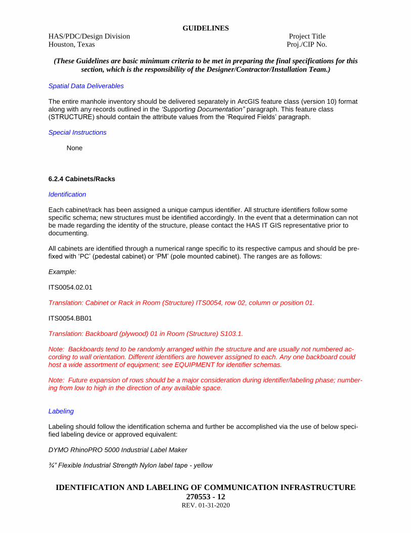
Spatial Data Deliverables The entire manhole inventory should be delivered separately in ArcGIS feature class (version 10) format along with any records outlined in the ‘Supporting Documentation” paragraph. This feature class (STRUCTURE) should contain the attribute values from the ‘Required Fields’ paragraph. Special Instructions None 6.2.4 Cabinets/Racks Identification Each cabinet/rack has been assigned a unique campus identifier. All structure identifiers follow some specific schema; new structures must be identified accordingly. In the event that a determination can not be made regarding the identity of the structure, please contact the HAS IT GIS representative prior to documenting. All cabinets are identified through a numerical range specific to its respective campus and should be pre-fixed with ‘PC’ (pedestal cabinet) or ‘PM’ (pole mounted cabinet). The ranges are as follows: Example: ITS0054.02.01 Translation: Cabinet or Rack in Room (Structure) ITS0054, row 02, column or position 01. ITS0054.BB01 Translation: Backboard (plywood) 01 in Room (Structure) S103.1.
Note: Backboards tend to be randomly arranged within the structure and are usually not numbered ac-cording to wall orientation. Different identifiers are however assigned to each. Any one backboard could host a wide assortment of equipment; see EQUIPMENT for identifier schemas. Note: Future expansion of rows should be a major consideration during identifier/labeling phase; number-ing from low to high in the direction of any available space. Labeling Labeling should follow the identification schema and further be accomplished via the use of below speci-fied labeling device or approved equivalent: DYMO RhinoPRO 5000 Industrial Label Maker ¾” Flexible Industrial Strength Nylon label tape - yellow
GUIDELINES HAS/PDC/Design Division Project Title Houston, Texas Proj./CIP No.
(These Guidelines are basic minimum criteria to be met in preparing the final specifications for this
section, which is the responsibility of the Designer/Contractor/Installation Team.)
IDENTIFICATION AND LABELING OF COMMUNICATION INFRASTRUCTURE
270553 - 13 REV. 01-31-2020
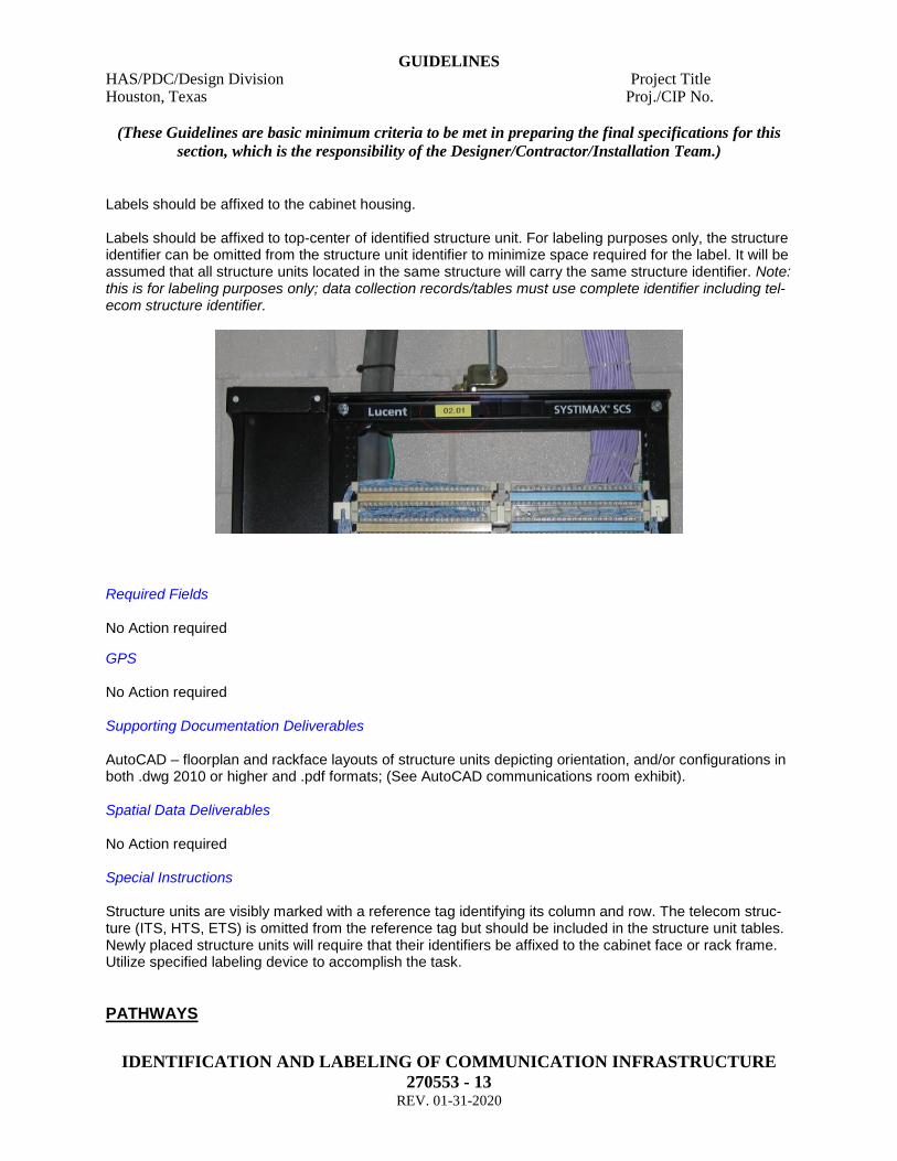
Labels should be affixed to the cabinet housing. Labels should be affixed to top-center of identified structure unit. For labeling purposes only, the structure identifier can be omitted from the structure unit identifier to minimize space required for the label. It will be assumed that all structure units located in the same structure will carry the same structure identifier. Note: this is for labeling purposes only; data collection records/tables must use complete identifier including tel-ecom structure identifier.
Required Fields No Action required
GPS No Action required Supporting Documentation Deliverables AutoCAD – floorplan and rackface layouts of structure units depicting orientation, and/or configurations in both .dwg 2010 or higher and .pdf formats; (See AutoCAD communications room exhibit). Spatial Data Deliverables No Action required Special Instructions Structure units are visibly marked with a reference tag identifying its column and row. The telecom struc-ture (ITS, HTS, ETS) is omitted from the reference tag but should be included in the structure unit tables. Newly placed structure units will require that their identifiers be affixed to the cabinet face or rack frame. Utilize specified labeling device to accomplish the task.
PATHWAYS
GUIDELINES HAS/PDC/Design Division Project Title Houston, Texas Proj./CIP No.
(These Guidelines are basic minimum criteria to be met in preparing the final specifications for this
section, which is the responsibility of the Designer/Contractor/Installation Team.)
IDENTIFICATION AND LABELING OF COMMUNICATION INFRASTRUCTURE
270553 - 14 REV. 01-31-2020
• Ductbank
• Trench
• Direct Buried
• Cable Tray Identification Each Pathway has been assigned a unique GIS database identifier. This identifier serves as a primary-key for each database record. Each record contains additional fields and values relative to the feature identified by the primary-key. All pathway identifiers follow a specific schema; new pathways must be identified accordingly. In the event that a determination cannot be made regarding the identification of a pathway, please contact an HAS IT GIS representative prior to documenting. All pathways are identified through a numerical range with prefix characters specific to a respective air-port campus, technology asset designation, and feature-category. Airport Campus Characters: IAH: I HOU: H EFD: E Asset Designation Character: Technology: T Feature-Category Characters: Structure: S Pathway: P Equipment: E Cable: C Numerical Range: 0000 – 9999 Example: ITP0054 (IAH Pathway), HTP0054 (HOU Pathway), ETP0054 (EFD Pathway) Labeling Pathways are identified for the purposes of GIS referencing and are linked to structure inventories but are not physically labeled per current guidelines. Required Fields
GUIDELINES HAS/PDC/Design Division Project Title Houston, Texas Proj./CIP No.
(These Guidelines are basic minimum criteria to be met in preparing the final specifications for this
section, which is the responsibility of the Designer/Contractor/Installation Team.)
IDENTIFICATION AND LABELING OF COMMUNICATION INFRASTRUCTURE
270553 - 15 REV. 01-31-2020
Each pathway requires that specific data be collected per unit. GPS equipment should be formatted to account for this information. CONDUIT_SIZE COMMENTS AIRPORT HAS_ENCASEMENT AGENCY CONDUIT_QTY PATH_ID PATH_NUMBER PATH_TYPE END1_COORD_X END1_COORD_Y END1_COORD_Z END2_COORD_X END2_COORD_Y END2_COORD_Z HAS_LEVEL COLLECTION_DATE PROJECT TICKET LEGACY_ID PATHWAY_MATERIAL FROM_TELECOM_ID TO_TELECOM_ID TELECOM_ID PROJECT_CLASS DEPTH_END1 DEPTH_END2
GPS

GUIDELINES HAS/PDC/Design Division Project Title Houston, Texas Proj./CIP No.
(These Guidelines are basic minimum criteria to be met in preparing the final specifications for this
section, which is the responsibility of the Designer/Contractor/Installation Team.)
IDENTIFICATION AND LABELING OF COMMUNICATION INFRASTRUCTURE
270553 - 16 REV. 01-31-2020
Each pathway must be recorded as follows: Care should be taken to accurately locate the pathways prior to commencing with documentation. Continuous-line shots; taken on center. Line-shots should begin and end on-center of endpoint (structure) locations. Supporting Documentation Deliverables No action required Spatial Data Deliverables The entire pathway inventory should be delivered separately in ArcGIS feature class (version 10.x) format along with any records outlined in the ‘Supporting Documentation’ paragraph. This feature class (PATHWAY) should contain the attribute values from the ‘Required Fields’ paragraph. Special Instructions No action required
• Cable Tray Identification no requirements per current guidelines Required Fields no requirements per current guidelines GPS no requirements per current guidelines Supporting Documentation Deliverables no requirements per current guidelines Spatial Data Deliverables no requirements per current guidelines Special Instructions no requirements per current guidelines
PATHWAY UNITS
• Conduits Identification For deliverable purposes conduits are only being depicted via AutoCAD formats; i.e. butterfly diagrams or floorplans (see Exhibits: Communication Room Exhibit, Rackface Exhibit) In the outside plant environment, conduits should be identified where applicable by size, location and po-sition respective to their endpoints (structures) i.e. handhole wall, building access point, etc. Further, on manhole / handhole butterfly diagrams, OSP conduits are depicted relevant to their size, posi-tion and orientation. As a general rule, conduits are identified left-to-right and top-to-bottom as you’re fac-ing the wall to be inventoried and should be prefixed with ‘CD’ on the AutoCAD documents.
GUIDELINES HAS/PDC/Design Division Project Title Houston, Texas Proj./CIP No.
(These Guidelines are basic minimum criteria to be met in preparing the final specifications for this
section, which is the responsibility of the Designer/Contractor/Installation Team.)
IDENTIFICATION AND LABELING OF COMMUNICATION INFRASTRUCTURE
270553 - 17 REV. 01-31-2020
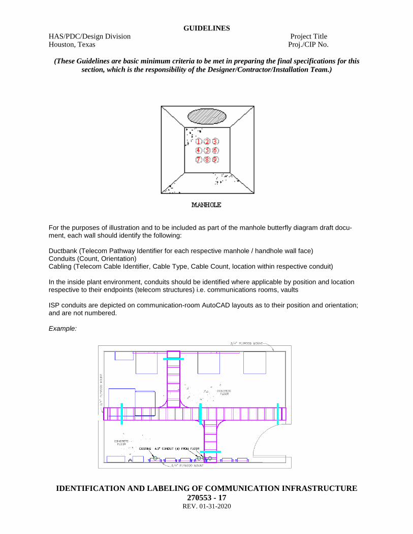
For the purposes of illustration and to be included as part of the manhole butterfly diagram draft docu-ment, each wall should identify the following: Ductbank (Telecom Pathway Identifier for each respective manhole / handhole wall face) Conduits (Count, Orientation) Cabling (Telecom Cable Identifier, Cable Type, Cable Count, location within respective conduit) In the inside plant environment, conduits should be identified where applicable by position and location respective to their endpoints (telecom structures) i.e. communications rooms, vaults ISP conduits are depicted on communication-room AutoCAD layouts as to their position and orientation; and are not numbered. Example:

GUIDELINES HAS/PDC/Design Division Project Title Houston, Texas Proj./CIP No.
(These Guidelines are basic minimum criteria to be met in preparing the final specifications for this
section, which is the responsibility of the Designer/Contractor/Installation Team.)
IDENTIFICATION AND LABELING OF COMMUNICATION INFRASTRUCTURE
270553 - 18 REV. 01-31-2020
Labeling Not physically labeled per current guidelines. Required Fields Conduit counts, and size as prescribed in the pathway sub-topic GPS No action required Supporting Documentation Deliverables AutoCAD manhole / handhole butterfly diagrams for OSP conduits and communication-room layouts for ISP conduits; (See manhole / handhole AutoCAD butterfly exhibit).). Spatial Data Deliverables No action required Special Instructions See note regarding annotation above.
CABLE
• Inside Plant Copper
• Inside Plant Fiber (Single-Mode, Multi-Mode)
• Outside Plant Copper
• Outside Plant Fiber (Single-Mode, Multi-Mode)
• Inside Plant Copper Coax
• Outside Plant Copper Coax
• Inside Plant Hybrid
• Outside Plant Hybrid Identification Each Cable has been assigned a unique GIS database identifier. This identifier serves as a primary-key for each database record. Each record contains additional fields and values relative to the feature identi-fied by the primary-key. All cable identifiers follow a specific schema; new cable must be identified accordingly. In the event that a determination cannot be made regarding the identification of a cable-run, please contact an HAS IT GIS representative prior to documenting.

GUIDELINES HAS/PDC/Design Division Project Title Houston, Texas Proj./CIP No.
(These Guidelines are basic minimum criteria to be met in preparing the final specifications for this
section, which is the responsibility of the Designer/Contractor/Installation Team.)
IDENTIFICATION AND LABELING OF COMMUNICATION INFRASTRUCTURE
270553 - 19 REV. 01-31-2020
All cables are identified through a numerical range with prefix characters specific to a respective airport campus, technology asset designation, and feature-category. Airport Campus Characters: IAH: I HOU: H EFD: E Asset Designation Character: Technology: T Feature-Category Characters: Structure: S Pathway: P Equipment: E Cable: C Numerical Range: 0000 – 9999 Example: ITC0054 (IAH Cable), HTC0054 (HOU Cable), ETC0054 (EFD Cable) Note: When planning to identify newly constructed or newly placed HAS assets, the contractor is ex-pected to coordinate with the HAS IT GIS staff prior to labeling. This action will account for all identifiers previously assigned and prevent duplications or omissions. Labeling Labels should be affixed to all connection ends of identified cable and on any visible length at key access points, i.e. manhole, handhole cable ladder runs. "All adhesive inside/outside plant cable labels for horizontal and backbone cables shall be cov-ered with clear heat shrink tubing" Required Fields Each cable requires that specific data be collected per unit. GPS equipment should be formatted to ac-count for this information. TELECOM_ID LEGACY_ID AIRPORT

GUIDELINES HAS/PDC/Design Division Project Title Houston, Texas Proj./CIP No.
(These Guidelines are basic minimum criteria to be met in preparing the final specifications for this
section, which is the responsibility of the Designer/Contractor/Installation Team.)
IDENTIFICATION AND LABELING OF COMMUNICATION INFRASTRUCTURE
270553 - 20 REV. 01-31-2020
AGENCY CABLE_TYPE CABLE_COUNT FROM_TELECOM_ID TO_TELECOM_ID FROM_STRUCTURE_UNIT_ID TO_STRUCTURE_UNIT_ID FROM_EQUIPMENT_ID TO_EQUIPMENT_ID HAS_LEVEL PROJECT PROJECT_CLASS COLLECTION_DATE SYMANTEC_TICKET COMMENTS
GPS Each cable should be recorded as follows: OSP – continuous GPS shot between identified structures ISP – conventional GPS services are unavailable inside-plant; therefore inside-plant cabling will need to be digitized and included in the ArcGIS CABLE feature class spatial data deliverable. Supporting Documentation Deliverables ISP Horizontal cabling (see Exhibits – iPatch SOP.pdf). Cable testing records; .pdf format (see Exhibits – C_Cable Test Exhibit, F_Cable Test Exhibit.pdf). Butterfly diagrams (OSP) AutoCAD format; (See AutoCAD manhole / handhole butterfly exhibit). Spatial Data Deliverables The entire OSP cable inventory should be delivered separately in ArcGIS feature class (version 10.x) format along with any records outlined in the ‘Supporting Documentation’ paragraph. This feature class (CABLE) should contain the attribute values from the ‘Required Fields’ paragraph. No Spatial Data required for ISP inventory.
GUIDELINES HAS/PDC/Design Division Project Title Houston, Texas Proj./CIP No.
(These Guidelines are basic minimum criteria to be met in preparing the final specifications for this
section, which is the responsibility of the Designer/Contractor/Installation Team.)
IDENTIFICATION AND LABELING OF COMMUNICATION INFRASTRUCTURE
270553 - 21 REV. 01-31-2020
Special Instructions No cable testing should be conducted on any live circuit. Ensure that necessary precautions are ob-served to guarantee existing network integrity and no active circuits are impacted.
• Jumper Cables / Patch Cords / Cross-Connects: Identification No action required Labeling No action required Required Fields Refer to iPatch SOP (see Exhibits - iPatch SOP.pdf) GPS No action required Supporting Documentation Deliverables ISP cabling (see Exhibits - iPatch SOP.pdf) Spatial Data Deliverables No action required Special Instructions No cable testing should be conducted on any live circuit. Ensure that necessary precautions are ob-served to guarantee existing network integrity and no active circuits are impacted. As iPatch is the administration application for these assets - all project managers, inspectors and consult-ants overseeing ‘new-build’ infrastructure configurations must strictly adhere to guidelines specified in the iPatch SOP (see Exhibits - iPatch SOP.pdf). Further, you must contact an iPatch database administrator directly to coordinate the data collection and documentation-deliverable evolution. Bulk import of key iPatch modeling components can be facilitated by utilization of a specifically formatted spreadsheet (see Exhibits - iPatch Bulk Import.xls). Updates/changes to fiber patching can be facilitated by utilization of a specifically formatted cut-sheet (see Exhibits – Fiber Patching Cut Sheets.xls).

GUIDELINES HAS/PDC/Design Division Project Title Houston, Texas Proj./CIP No.
(These Guidelines are basic minimum criteria to be met in preparing the final specifications for this
section, which is the responsibility of the Designer/Contractor/Installation Team.)
IDENTIFICATION AND LABELING OF COMMUNICATION INFRASTRUCTURE
270553 - 22 REV. 01-31-2020
EQUIPMENT
• Termination Point
• Patch Panel
• Network Switch
• 110 Block
• Splice Enclosure
• Cable Transition
• EFSO Button
• Copper Modem
• Tap
• Camera Identification All Equipment has been assigned a unique GIS database identifier. This identifier serves as a primary-key for each database record. Each record contains additional fields and values relative to the feature identified by the primary-key. All equipment identifiers follow a specific schema; new equipment must be identified accordingly. In the event that a determination cannot be made regarding the identification of a piece of equipment, please contact an HAS IT GIS representative prior to documenting. All equipment is identified through a numerical range with prefix characters specific to a respective airport campus, technology asset designation, and feature-category. Airport Campus Characters: IAH: I HOU: H EFD: E Asset Designation Character: Technology: T Feature-Category Characters: Structure: S Pathway: P Equipment: E Cable: C Numerical Range: 0000 – 9999

GUIDELINES HAS/PDC/Design Division Project Title Houston, Texas Proj./CIP No.
(These Guidelines are basic minimum criteria to be met in preparing the final specifications for this
section, which is the responsibility of the Designer/Contractor/Installation Team.)
IDENTIFICATION AND LABELING OF COMMUNICATION INFRASTRUCTURE
270553 - 23 REV. 01-31-2020
Example: ITE0054 (IAH Equipment), HTE0054 (HOU Equipment), ETE0054 (EFD Equipment) Labeling Labeling should follow the identification schema and further be accomplished via the use of below speci-fied labeling device or approved equivalent: DYMO rhinoPRO 5000 Industrial Label Maker ¾” Flexible Industrial Strength Nylon label tape - yellow Labels should be affixed to the splice enclosure housing. Label placement should be affixed to or as near to equipment as possible. Required Fields All equipment requires that specific data be collected per unit. GPS equipment should be formatted to account for this information. EQUIPMENT_ID TELECOM_ID SYMANTEC_TICKET CABLE_ID TELECOM_CABLE_ID LEGACY_CABLE_ID AIRPORT AGENCY PROJECT PROJECT_CLASS COLLECTION_DATE COMMENTS LEGACY_ID EQUIPMENT_TYPE HAS_LEVEL
GPS No action required for ISP equipment

GUIDELINES HAS/PDC/Design Division Project Title Houston, Texas Proj./CIP No.
(These Guidelines are basic minimum criteria to be met in preparing the final specifications for this
section, which is the responsibility of the Designer/Contractor/Installation Team.)
IDENTIFICATION AND LABELING OF COMMUNICATION INFRASTRUCTURE
270553 - 24 REV. 01-31-2020
Each splice enclosure (OSP) should be recorded as follows: Single shots; taken on-center. Offset shots or other means of location are acceptable for splice enclo-sures not available to satellite coverage but these shots or options must be coordinated with an HAS-IT GIS contact prior to. Supporting Documentation Deliverables AutoCAD – one-line diagram of ACCESSIBLE for splice enclosures depicting cable identifiers, connec-tions and cable counts for each splice enclosure in both .dwg 2010 or higher and .pdf formats; (See Au-toCAD splice enclosure exhibit). AutoCAD – rackface layouts of structure units depicting orientation, and/or configurations in both .dwg 2010 or higher and .pdf formats; (See AutoCAD communications room exhibit). Spatial Data Deliverables The entire equipment inventory should be delivered separately in ArcGIS feature class (version 10.x) for-mat along with any records outlined in the ‘Supporting Documentation” paragraph. This feature class (EQUIPMENT) should contain the attribute values from the ‘Required Fields’ paragraph. Special Instructions Do not attempt to open a splice enclosure that appears to be in a fragile state or does not provide for ready access (sealed). Note in ‘comments’ field that the enclosure was inaccessible. Do not move, adjust ‘live’ equipment in order to identify or label. Ask for assistance from qualified HAS Technology Infrastructure personnel. Do not disconnect cabling in order to identify or label. Ask for assistance from qualified HAS Technology Infrastructure personnel.
• Outlets Identification Each outlet-faceplate is identified specific to its servicing IDF; regardless of the number of outlets within a given location. All outlet-faceplate ports are labeled to correspond with the servicing IDF panel port. Note: These space identifiers are architectural identifiers, and are designated by reference to the HAS Infrastructure schema for identifying building spaces. This is not a GIS Technology Infrastructure database identifier.
GUIDELINES HAS/PDC/Design Division Project Title Houston, Texas Proj./CIP No.
(These Guidelines are basic minimum criteria to be met in preparing the final specifications for this
section, which is the responsibility of the Designer/Contractor/Installation Team.)
IDENTIFICATION AND LABELING OF COMMUNICATION INFRASTRUCTURE
270553 - 25 REV. 01-31-2020
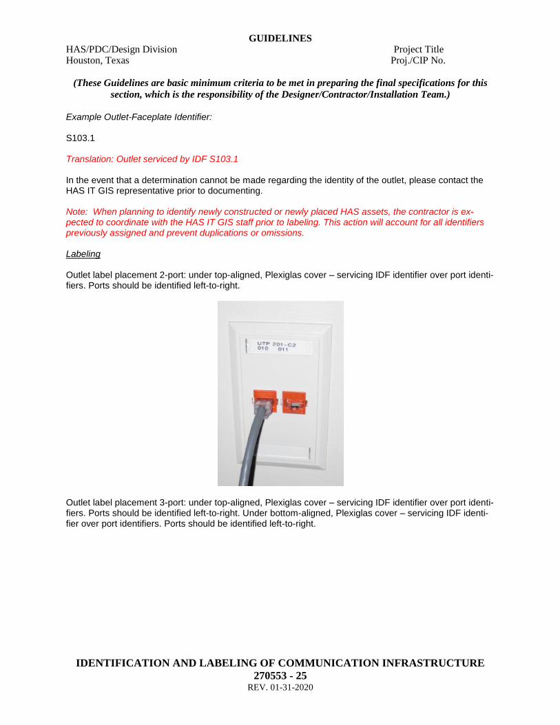
Example Outlet-Faceplate Identifier: S103.1 Translation: Outlet serviced by IDF S103.1 In the event that a determination cannot be made regarding the identity of the outlet, please contact the HAS IT GIS representative prior to documenting. Note: When planning to identify newly constructed or newly placed HAS assets, the contractor is ex-pected to coordinate with the HAS IT GIS staff prior to labeling. This action will account for all identifiers previously assigned and prevent duplications or omissions. Labeling Outlet label placement 2-port: under top-aligned, Plexiglas cover – servicing IDF identifier over port identi-fiers. Ports should be identified left-to-right.
Outlet label placement 3-port: under top-aligned, Plexiglas cover – servicing IDF identifier over port identi-fiers. Ports should be identified left-to-right. Under bottom-aligned, Plexiglas cover – servicing IDF identi-fier over port identifiers. Ports should be identified left-to-right.

GUIDELINES HAS/PDC/Design Division Project Title Houston, Texas Proj./CIP No.
(These Guidelines are basic minimum criteria to be met in preparing the final specifications for this
section, which is the responsibility of the Designer/Contractor/Installation Team.)
IDENTIFICATION AND LABELING OF COMMUNICATION INFRASTRUCTURE
270553 - 26 REV. 01-31-2020
Outlet label placement 4-port: under top-aligned, Plexiglas cover – servicing IDF identifier over port identi-fiers. Ports should be identified left-to-right. Under bottom-aligned, Plexiglas cover – servicing IDF identi-fier over port identifiers. Ports should be identified left-to-right. Follow 3-port example. Outlet label placement 6-port: under top-aligned, Plexiglas cover – servicing IDF identifier over port identi-fiers. Ports should be identified left-to-right. Any mid-faceplate ports will require an adhesive label - servic-ing IDF identifier over port identifiers. Ports should be identified left-to-right. Under bottom-aligned, Plexi-glas cover – servicing IDF identifier over port identifiers. Ports should be identified left-to-right. These types of outlets are ‘Non-Standard’. Required Fields No action required GPS OSP – No GPS action required ISP – No GPS action required Supporting Documentation Deliverables Additional documentation records are required to support iPatch data. The documentation is as follows: AutoCAD – floorplan (where applicable) depicting outlet locations; (See AutoCAD communications room exhibit).). Spatial Data Deliverables No action required Special Instructions
GUIDELINES HAS/PDC/Design Division Project Title Houston, Texas Proj./CIP No.
(These Guidelines are basic minimum criteria to be met in preparing the final specifications for this
section, which is the responsibility of the Designer/Contractor/Installation Team.)
IDENTIFICATION AND LABELING OF COMMUNICATION INFRASTRUCTURE
270553 - 27 REV. 01-31-2020
Outlets are visibly marked with a reference tag indicating the outlet identifier. Additionally any port associ-ated to the outlet is identified with a port number related specifically back to its respective servicing equipment. Newly placed outlets will require that their identifiers be affixed to the outlet face. Utilize speci-fied labeling device to accomplish the task.
• Door Contacts Identification Each door-contact sensor (without card-reader) is identified by an alpha-numeric sequence specific to its location. All door-contact identifiers are coded with building or complex character, followed by level char-acter, followed by numerical sequence character, followed by ‘CCM’ designation. “CCM’ is an acronym for ‘Control Contact Monitoring.’ Example Outlet-Faceplate Identifier: B-2057CCM Translation: B (building/complex character) Terminal B 2 (level character) Level 2 057 (numerical sequence character) Contact # 057 CCM (CCM designation) Control Contact Monitoring In the event that a determination cannot be made regarding the identity of a door contact, please contact the HAS IT Project Manager prior to documenting. Note: When planning to identify newly constructed or newly placed HAS assets, the contractor is ex-pected to coordinate with the HAS IT Project Manager prior to labeling. This action will account for all identifiers previously assigned and prevent duplications or omissions. Labeling Door-contacts (without card-reader) require identifier plates per ‘Special Instruction’ specification below Required Fields TBD
GPS OSP – No GPS action required ISP – No GPS action required

GUIDELINES HAS/PDC/Design Division Project Title Houston, Texas Proj./CIP No.
(These Guidelines are basic minimum criteria to be met in preparing the final specifications for this
section, which is the responsibility of the Designer/Contractor/Installation Team.)
IDENTIFICATION AND LABELING OF COMMUNICATION INFRASTRUCTURE
270553 - 28 REV. 01-31-2020
Supporting Documentation Deliverables AutoCAD floorplans indicating door contact location including label plate identifier annotation Spatial Data Deliverables No action required Special Instructions Install Black Lexan Label Plate: sized 1 ½” X 4”, black background, white lettering and Door Alarm Identi-fier engraved (i.e. B-2057CCM). Locate plate on door frame above contact. Clean door frame prior to placement. Affix with 3M double-sided tape. Provide paper and electronic copies (.pdf format) of all Electronic Lock Permits and Submittal Documents for any door requiring City of Houston door lock permit to the HAS IT Project Manager prior to Acceptance Testing.
• Card Readers Identification Each electronic lock is identified by an alpha-numeric sequence specific to its location. All electronic lock identifiers are coded with building or complex character, followed by level character, followed by numeri-cal sequence character. Example Outlet-Faceplate Identifier: C-1015 Translation: C (building/complex character) Terminal C 1 (level character) Level 1 015 (numerical sequence character) Lock # 015 In the event that a determination cannot be made regarding the identity of a door contact, please contact the HAS IT Project Manager prior to documenting. Note: When planning to identify newly constructed or newly placed HAS assets, the contractor is ex-pected to coordinate with the HAS IT Project Manager prior to labeling. This action will account for all identifiers previously assigned and prevent duplications or omissions. Labeling Electronic locks require identifier plates per ‘Special Instruction’ specification below Required Fields

GUIDELINES HAS/PDC/Design Division Project Title Houston, Texas Proj./CIP No.
(These Guidelines are basic minimum criteria to be met in preparing the final specifications for this
section, which is the responsibility of the Designer/Contractor/Installation Team.)
IDENTIFICATION AND LABELING OF COMMUNICATION INFRASTRUCTURE
270553 - 29 REV. 01-31-2020
TBD
GPS OSP – No GPS action required ISP – No GPS action required Supporting Documentation Deliverables AutoCAD floorplans indicating card reader location including label plate identifier annotation Spatial Data Deliverables No action required Special Instructions Install Black Lexan Label Plate: sized approximately 3 ¼” X 5 ½”, black background, white lettering and Card Reader Identifier engraved (i.e. C-1015). Affix plate to single-gang cabinet with 5/32” screws. Provide paper and electronic copies (.pdf format) of all Electronic Lock Permits and Submittal Documents for any door requiring City of Houston door lock permit to the HAS IT Project Manager prior to Acceptance Testing.
CONNECTIONS
• Ports Identification Each port has been assigned an identifier; combined with the equipment identifier, the sequence be-comes unique. Therefore port identifiers may be replicated on separate pieces of equipment because again, the true and complete port ID is coupled to the equipment ID. Example: 100.20.01.02.35-39 (equipment ID) + FP03 = 100.20.01.02.35-39 FP03 100.25.01.01.12-17 (equipment ID) + FP03 = 100.25.01.01.12-17 FP03
Fiber port 03 is replicated on two different pieces of equipment. Coupling it to the equipment ID makes the string unique
All ports are identified through a numerical range specific to its respective equipment. Ports may be pre-fixed with ‘FP’ (fiber port) or ‘CP’ (copper port) as is pertinent to the cable category and space allows on the equipment.
GUIDELINES HAS/PDC/Design Division Project Title Houston, Texas Proj./CIP No.
(These Guidelines are basic minimum criteria to be met in preparing the final specifications for this
section, which is the responsibility of the Designer/Contractor/Installation Team.)
IDENTIFICATION AND LABELING OF COMMUNICATION INFRASTRUCTURE
270553 - 30 REV. 01-31-2020
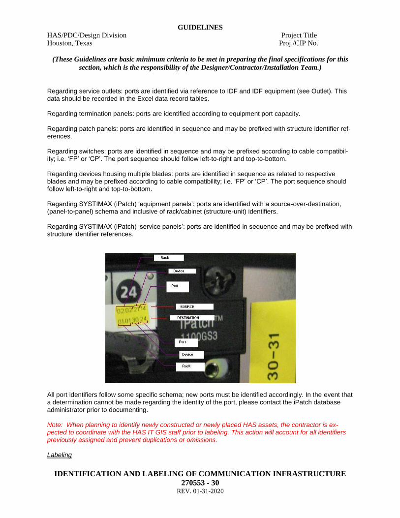
Regarding service outlets: ports are identified via reference to IDF and IDF equipment (see Outlet). This data should be recorded in the Excel data record tables. Regarding termination panels: ports are identified according to equipment port capacity. Regarding patch panels: ports are identified in sequence and may be prefixed with structure identifier ref-erences. Regarding switches: ports are identified in sequence and may be prefixed according to cable compatibil-ity; i.e. ‘FP’ or ‘CP’. The port sequence should follow left-to-right and top-to-bottom. Regarding devices housing multiple blades: ports are identified in sequence as related to respective blades and may be prefixed according to cable compatibility; i.e. ‘FP’ or ‘CP’. The port sequence should follow left-to-right and top-to-bottom. Regarding SYSTIMAX (iPatch) ‘equipment panels’: ports are identified with a source-over-destination, (panel-to-panel) schema and inclusive of rack/cabinet (structure-unit) identifiers. Regarding SYSTIMAX (iPatch) ‘service panels’: ports are identified in sequence and may be prefixed with structure identifier references.
All port identifiers follow some specific schema; new ports must be identified accordingly. In the event that a determination cannot be made regarding the identity of the port, please contact the iPatch database administrator prior to documenting. Note: When planning to identify newly constructed or newly placed HAS assets, the contractor is ex-pected to coordinate with the HAS IT GIS staff prior to labeling. This action will account for all identifiers previously assigned and prevent duplications or omissions. Labeling
GUIDELINES HAS/PDC/Design Division Project Title Houston, Texas Proj./CIP No.
(These Guidelines are basic minimum criteria to be met in preparing the final specifications for this
section, which is the responsibility of the Designer/Contractor/Installation Team.)
IDENTIFICATION AND LABELING OF COMMUNICATION INFRASTRUCTURE
270553 - 31 REV. 01-31-2020
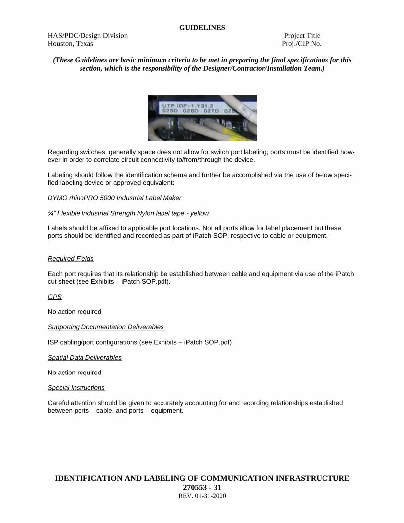
Regarding switches: generally space does not allow for switch port labeling; ports must be identified how-ever in order to correlate circuit connectivity to/from/through the device. Labeling should follow the identification schema and further be accomplished via the use of below speci-fied labeling device or approved equivalent: DYMO rhinoPRO 5000 Industrial Label Maker ¾” Flexible Industrial Strength Nylon label tape - yellow Labels should be affixed to applicable port locations. Not all ports allow for label placement but these ports should be identified and recorded as part of iPatch SOP; respective to cable or equipment. Required Fields Each port requires that its relationship be established between cable and equipment via use of the iPatch cut sheet (see Exhibits – iPatch SOP.pdf). GPS No action required Supporting Documentation Deliverables ISP cabling/port configurations (see Exhibits – iPatch SOP.pdf) Spatial Data Deliverables No action required Special Instructions Careful attention should be given to accurately accounting for and recording relationships established between ports – cable, and ports – equipment.

GUIDELINES HAS/PDC/Design Division Project Title Houston, Texas Proj./CIP No.
(These Guidelines are basic minimum criteria to be met in preparing the final specifications for this
section, which is the responsibility of the Designer/Contractor/Installation Team.)
IDENTIFICATION AND LABELING OF COMMUNICATION INFRASTRUCTURE
270553 - 32 REV. 01-31-2020
7 STANDARD OPERATING PROCEDURES – BEST PRACTICES 7.1 Data Collection Methodology 7.1.1 This section includes a general outline of procedures that can be utilized towards the collection and processing of HAS’ IT physical data requirements. The outline establishes some of the recommended methods which have proven to be most successful during previous data collection cycles. This guide does not mandate adherence to these methods provided that the contracting party can deter-mine a like process to produce the intended results. Said process must however provide for the specific formatting of all aforementioned physical data deliverables including data record tables, .DWF / .DWG, .PDF, feature class, feature class, and photo imagery.
Note: Safety is paramount and discussions with regard to OSHA and other regulatory or governing au-thorities including Airport Operations must be coordinated with the HAS IT representatives prior to com-
mencement of any project scope. 7.2 Outside Plant 7.2.1 Identify outside plant network locations as defined by project scope of work including all structures, pathways, cable and equipment. This requires extensive communication and coordination with HAS air-port campus authorities before and during the evolution. Contracting parties will be provided with respec-tive contact information prior to commencement of data collection effort. Coordinate with HAS IT representative to determine existing network identifiers and to specify any new network identifiers that must be incorporated into data deliverables. If applicable to the GPS equipment that will be utilized to collect data, format custom projections to cam-pus, format code-list. GPS locate structures; ensure all attribute fields are populated. For MH, HH produce field sketch - butter-fly layout depicting pathways unit counts orientation; cable types / counts, location. These field sketches should be used to create AutoCAD .DWF / .DWG deliverables. Produce photo imagery GPS locate all splice enclosures, slack loops. Label all end-equipment, splice enclosures, slack loops, cable, pullboxes, cabinets, pedestals. Stamp all MH, HH per guidelines. GPS locate pathways; ensure all attribute fields are populated. Physically locate outside plant associated equipment; ensure all attribute fields are populated. Building Access Points can be approximated where the PATHWAY intersects the building face for pur-poses of GPS data collection; single-shot. GPS locate cable routing; ensure all attribute fields are populated including end-equipment identifiers.
GUIDELINES HAS/PDC/Design Division Project Title Houston, Texas Proj./CIP No.
(These Guidelines are basic minimum criteria to be met in preparing the final specifications for this
section, which is the responsibility of the Designer/Contractor/Installation Team.)
IDENTIFICATION AND LABELING OF COMMUNICATION INFRASTRUCTURE
270553 - 33 REV. 01-31-2020
QA/ QC to ensure that all data relationships have been established; i.e. equipment-structure, structure-pathways, pathways-cable and that all attribute fields have been populated. Finalize, format deliverables 7.3 Inside Plant 7.3.1 Identify inside plant network locations as defined by project scope of work including all structures, cable and equipment. This requires extensive communication and coordination with HAS airport campus authorities before and during the evolution. Contracting parties will be provided with respective contact information prior to commencement of data collection effort. Coordinate with iPatch database administrator to determine existing network identifiers and to specify any new network identifiers that must be incorporated into data deliverables. Prepare field sketch (floorplan, rackface) of interior space and equipment. Document and dimension structure space and contents required to generate layouts for the floorplan, cable ladder, conduit, room details, and Install details. Rackface layouts should be created in a separate document. These field sketches should be used to create AutoCAD .DWF / .DWG deliverables. Label all structure units, cable and equipment per guidelines. Record information specific to iPatch SOP for structure units, equipment, cable; this process will be cov-ered in depth at the coordination meeting held prior to commencement of data collection effort. This in-formation establishes infrastructure relationships that will be used to model the communications environ-ment. Test Cable. QA/ QC to ensure that all data relationships have been established; i.e. structure – structure, structure – structure units, structure units – equipment, equipment – ports, ports – cable. Finalize, format deliverables.

GUIDELINES HAS/PDC/Design Division Project Title Houston, Texas Proj./CIP No.
(These Guidelines are basic minimum criteria to be met in preparing the final specifications for this
section, which is the responsibility of the Designer/Contractor/Installation Team.)
IDENTIFICATION AND LABELING OF COMMUNICATION INFRASTRUCTURE
270553 - 34 REV. 01-31-2020
EXHIBITS