Embed Size (px)
Citation preview

SECTION 3
BASIC AUTOMATIC CONTROLS
UNIT 16
ADVANCED AUTOMATIC
CONTROLS—DIRECT DIGITAL
CONTROLS
(DDCS) AND PNEUMATICS
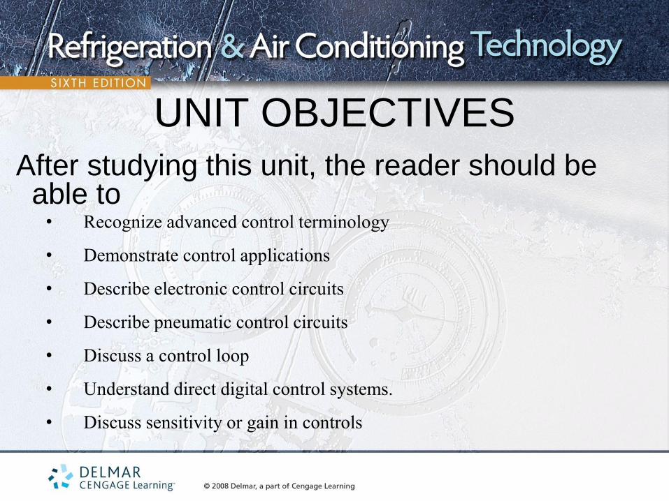
UNIT OBJECTIVES
After studying this unit, the reader should be able to
• Recognize advanced control terminology
• Demonstrate control applications
• Describe electronic control circuits
• Describe pneumatic control circuits
• Discuss a control loop
• Understand direct digital control systems.
• Discuss sensitivity or gain in controls
CONTROL APPLICATIONS • Older controls were manually activated and operated
• Thermostats and other simple controls were added to reduce human
contact with the equipment
• Automatic control systems require little human attention
• Large buildings can be maintained by a small staff of technicians
• Technicians need to be educated
– Should be able to calibrate controls
– Need to be able to interpret blueprints

TYPES OF CONTROL
SYSTEMS • First control systems started and stopped main system components
• Newer controls can modulate (start, stop, or adjust) the flow or operation of system components
• Control systems are divided into control loops
• Three basic components of a control system
– The sensor measures changes in conditions
– The controller sends an output signal
– The controlled device reacts to the controller
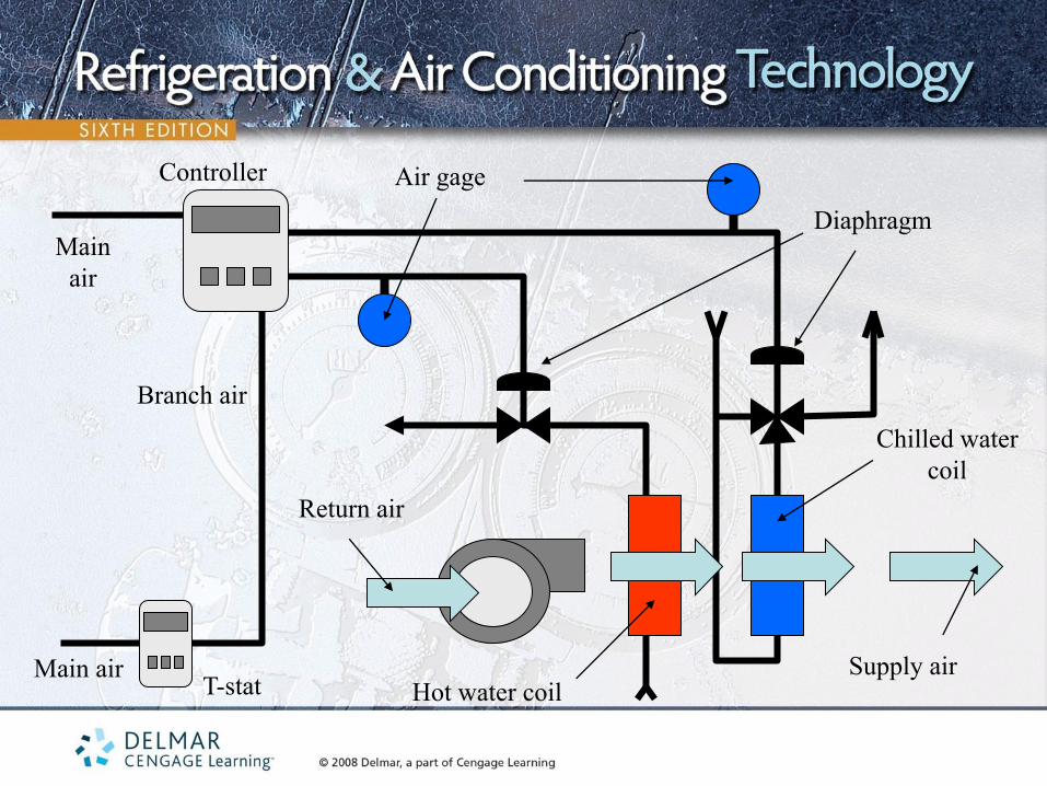
Return air
Supply air
Main
air
Main air
Controller
T-stat
Air gage
Diaphragm
Branch air
Hot water coil
Chilled water
coil
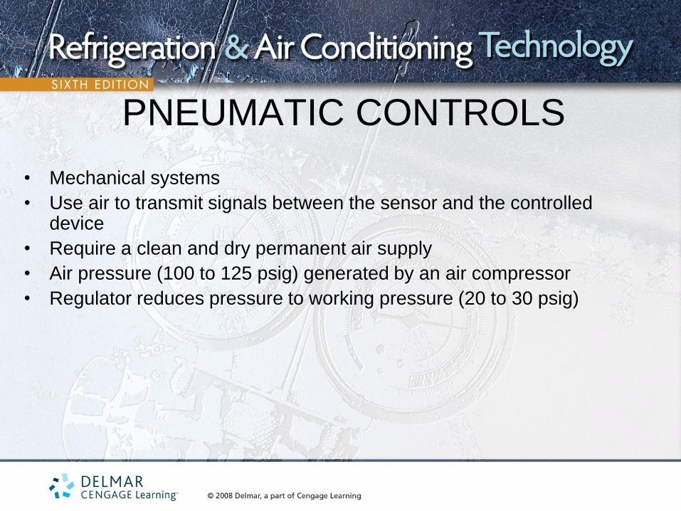
PNEUMATIC CONTROLS
• Mechanical systems
• Use air to transmit signals between the sensor and the controlled device
• Require a clean and dry permanent air supply
• Air pressure (100 to 125 psig) generated by an air compressor
• Regulator reduces pressure to working pressure (20 to 30 psig)
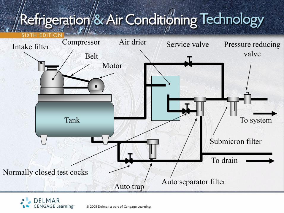
Intake filter Compressor
Belt
Motor
Tank
Air drier Pressure reducing
valve
Normally closed test cocks
Auto trap Auto separator filter
Submicron filter
To drain
To system
Service valve
To drain
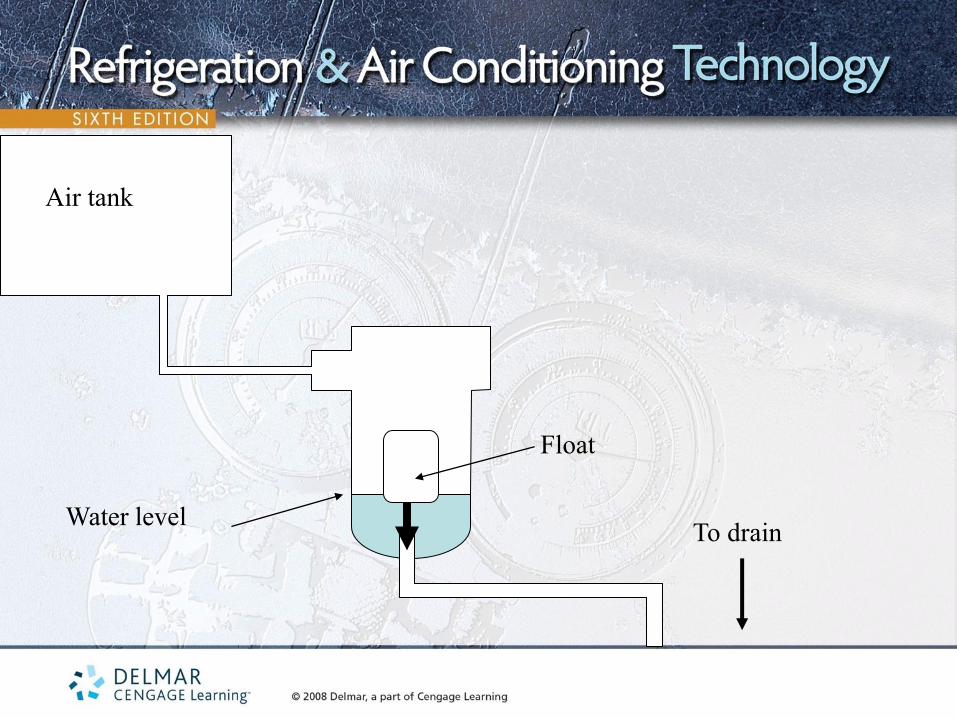
Air tank
Float
Water level

To drain
Air tank
Float
Water level

CLEANING AND DRYING CONTROL AIR
• Prefilter to the compressor
• Moisture is removed from the air
– Chilled water coil
– Desiccant
– Refrigerated drier (most common)
• High-density filters
– Final filtering stage
– Removes oil vapor and remaining liquid

CONTROL COMPONENTS • The pressure on control valves is equal to the air pressure multiplied by the
cross sectional area of the diaphragm
• Pilot positioners use a small volume of air to control a larger volume of air
• Fluid flow can be modulated
• Pressure gages used to measure pressure at the controls
• Can be used to control electric switches or circuits
• Electric devices can be used to control pneumatic controls
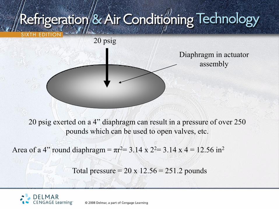
Diaphragm in actuator
assembly
20 psig
20 psig exerted on a 4” diaphragm can result in a pressure of over 250
pounds which can be used to open valves, etc.
Area of a 4” round diaphragm = πr2= 3.14 x 22= 3.14 x 4 = 12.56 in2
Total pressure = 20 x 12.56 = 251.2 pounds
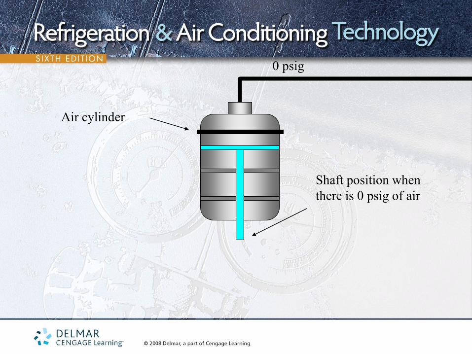
0 psig
Air cylinder
Shaft position when
there is 0 psig of air
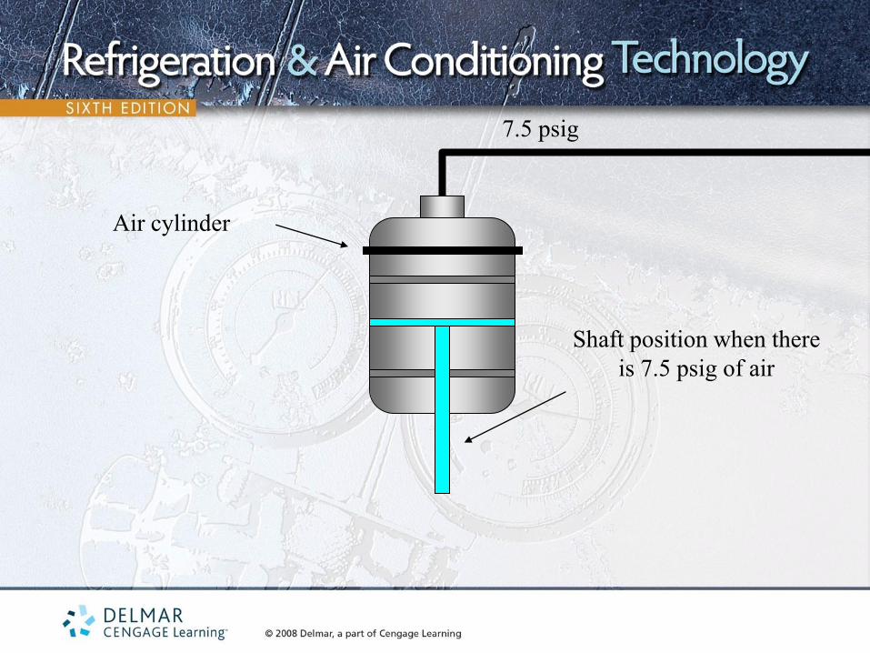
7.5 psig
Air cylinder
Shaft position when there
is 7.5 psig of air
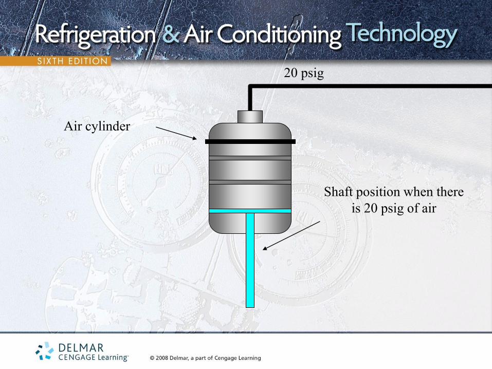
20 psig
Air cylinder
Shaft position when there
is 20 psig of air
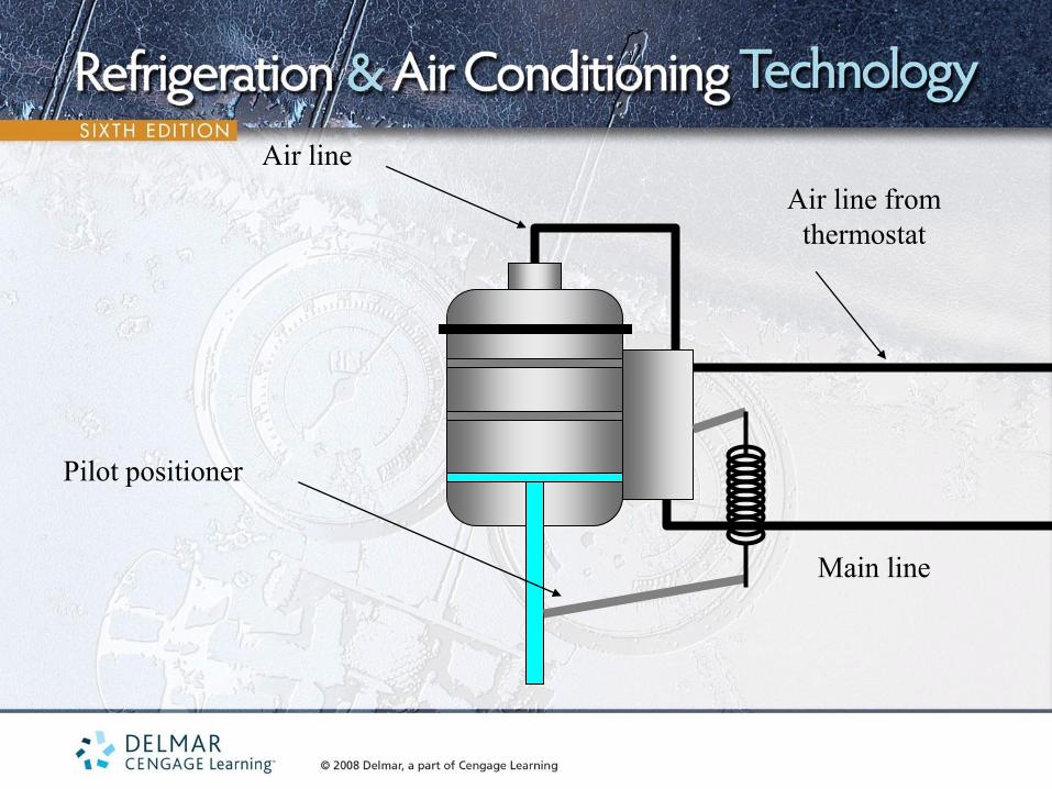
Air line
Air line from
thermostat
Main line
Pilot positioner
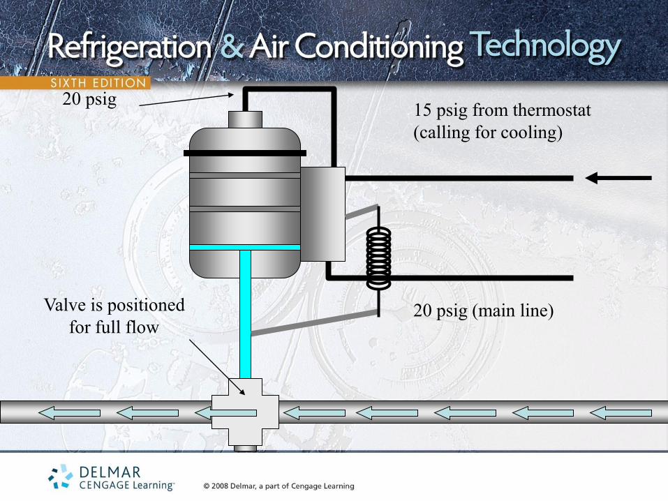
15 psig from thermostat
(calling for cooling)
20 psig (main line)
20 psig
Valve is positioned
for full flow
CONTROL COMPONENTS
• Fluid flow can be modulated
• Sensitivity or gain
– Pressure and temperature at fully open and fully closed positions
– Sensitivity = Δ pressure ÷ Δ temperature
– High sensitivity will cause the control to “hunt”
– Low sensitivity will result in noticeable change in space
temperature

45 degree supply water to cooling coil
55 degree return water from cooling coil
Bypass line
Valve positioned for full flow
through the cooling coil

45 degree supply water to cooling coil
55 degree return water from cooling coil
Bypass line
Valve positioned for partial flow
through the cooling coil
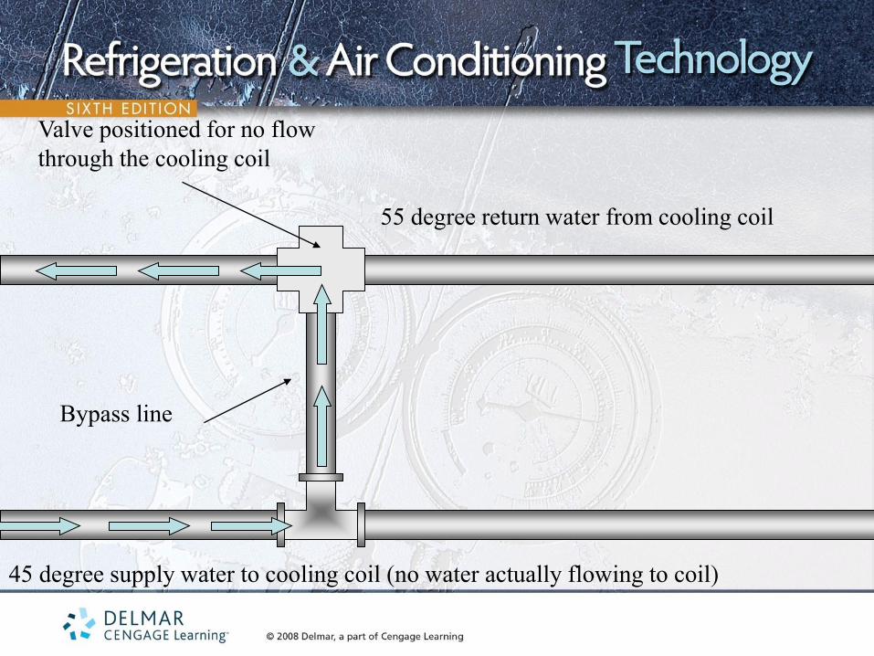
45 degree supply water to cooling coil (no water actually flowing to coil)
55 degree return water from cooling coil
Bypass line
Valve positioned for no flow
through the cooling coil

DIRECT DIGITAL
CONTROLS (DDC) • Referred to as DDC
• Operate at very low voltages
• Can be used to open, close, or modulate valves, dampers, motor
speeds, etc.
• Can be controlled from remote locations via computers
• Corrective actions can be taken from remote locations via computers
• System parameters can be observed

RESIDENTIAL ELECTRONIC CONTROLS • Entire board is evaluated, not the individual board components
• Use manufacturer’s diagnostic systems
• Boards are often treated as switches
• Boards often have diagnostic codes for troubleshooting
• Thermistors are often used
• Often equipped with DIP switches
– Allows control to be configured
– Allows user to customize system operation
• Status lights indicate mode of operation
UNIT SUMMARY - 1
• Older controls manually activated and operated
• Automatic control systems require little attention
• Newer controls modulate fluid flow
• Control systems are divided into control loops
• Control systems are made up of the sensor, controller and the controlled device
• Pneumatic control systems use air to transmit signals between the sensor and the controlled device

UNIT SUMMARY - 2 • Pneumatic systems require clean and dry air supply
• Control air used to position controlled devices
• Sensitivity = Δ pressure ÷ Δ temperature
• DDC can be used to open, close, or modulate valves, dampers, motor
speeds, and other devices
• Corrective actions can be taken from remote locations via computers
• Entire board is evaluated, not the individual board components