Embed Size (px)
Citation preview

SECTION 32 31 13
CHAIN LINK FENCE
PART 1 GENERAL
1.01 SUMMARY
A. Provide: 1. Chain link fence. 2. Fence accessories.
B. Related Sections:
1. Section 03 30 00 - Cast-in-Place Concrete 2. Section 31 22 10 - Site Grading
1.02 REFERENCES
A. ASTM: 1. A121 - Metallic Coated Carbon Steel Barbed Wire 2. A123 - Hot Dip Galvanized Coatings on Iron and Steel Products 3. A153 - Hot Dip Zinc Coating on Iron and Steel Hardware 4. A181 - Carbon Steel Forgings for Piping 5. A390 - Hot Dip Galvanized Steel Poultry Fence Fabric 6. A491 - Aluminum-Coated Steel Chain Link Fence Fabric 7. A780 - Repair of Damaged and Uncoated Areas of Hot Dip Galvanized Coatings 8. A817 - Metallic Coated Steel Wire for Chain Link Fence Fabric 9. A824 - Metallic Coated Steel Tension Wire for Chain Link Fence 10. C33 - Concrete Aggregates 11. C150 - Portland Cement 12. F567 - Installation of Chain Link Fence 13. F626 - Fence Fittings 14. F668 - PVC Coated Steel Chain Link Fence Fabric 15. F900 - Industrial Swing Gates 16. F1043 - Strength and Protective Coatings on Chain Link Fence Framework 17. F1083 - Pipe, Steel, Hot-Dipped Galvanized Welded for Fence Structures 18. F1184 - Industrial and Commercial Horizontal Slide Gates
1.03 SUBMITTALS
A. Product Data: Submit manufacturer’s technical data, finishes, dimensions of individual components and profiles, and installation instructions for fencing, fabric, gates, and accessories.
B. Shop Drawings:
1. Show locations of fences, posts, rails, tension wires, details of extended posts, extension arms, hardware, and accessories.
2. Indicate materials, dimensions, sizes, weights, and finishes of components. 3. Include plans, elevations, sections, details of post anchorage, attachment, bracing, and other
required installation and operational clearances.
C. Samples: 6-inch length of fabric wire for verification and selection of PVC color.
D. Product Certificates: For each type of chain-link fence and gate, signed by product manufacturer.
E. Testing: Strength test results for framing per ASTM F1043.
D-841.1 (Addendum 1 - 2/9/17)

1.04 QUALITY ASSURANCE
A. Provide chain link fences as complete units by single source including necessary erection accessories, fittings, and fastenings.
PART 2 PRODUCTS
2.01 MANUFACTURERS
A. Available Manufacturers: Subject to compliance with requirements, manufacturers offering galvanize steel fencing and fabric which may be incorporated in Work include: 1. Allied Tube and Conduit Corporation 2. American Fence Corporation 3. Ameristar Fence Products 4. Anchor Fence, Inc. 5. Cyclone Fence/United States Steel Corporation 6. Merchants Metals, Inc. www.merchantsmetals.com 7. Tymetal www.tymetal.com 8. Manufacturer of comparable products submitted in compliance with Section 01 25 13.
2.02 STEEL FABRIC
A. Material: 9 gage (0.148 inch plus 0.005 inch) finished size galvanized steel wires, 2-inch mesh, per ASTM A390.
B. Top selvages knuckled for fabric 60-inch high and under.
C. Top and bottom selvages twisted and barbed for fabric over 10-foot-high.
D. One-piece fabric widths for fencing up to 12-foot high.
E. Coating:
1. PVC weatherproof coating per ASTM F668. 2.03 FRAMING AND ACCESSORIES
A. Dimensions: Pipe, roll-formed, H-sections are outside dimensions, exclusive of coatings.
B. Steel Framework: Hot-dipped galvanized steel, ASTM F1083, not less than 1.8 ounce zinc per square foot of surface.
C. Fittings and Accessories: Galvanized, ASTM F626.
D. End, Corner, Pull Posts: Minimum sizes and weights as follows:
1. Over 6 feet fabric height, 2.875-inch outside diameter steel pipe, 5.79 pounds per lineal foot, or 3.5 inch by 3.5 inch roll-formed sections, 4.85 pounds per lineal foot.
E. Line Posts: Space 10 feet on center maximum, unless otherwise indicated, of following minimum sizes
and weights: 1. 6 feet to 8 feet fabric height, 2.375-inch outside diameter steel pipe, 3.65 pounds per lineal foot,
or 2.25-inch by 1.875-inch H-sections, 2.64 pounds per lineal foot.
F. Top Rail: 1. Manufacturer’s longest lengths. 2. Expansion type couplings, approximately 6 inches long, for each joint. 3. Provide means for attaching top rail securely to each gate, corner, pull, end post.
D-841.2 (Addendum 1 - 2/9/17)

4. 1.66-inch outside diameter pipe, 2.27 pounds per foot, or 1.625 inch by 1.25-inch roll-formed sections, 1.35 pounds per foot.
G. Wire Ties: 11 gage galvanized steel or 11 gage aluminum wire, to match fabric core material.
H. Post Brace Assembly:
1. Manufacturer’s standard adjustable brace at end, gate posts, both sides of corner and pull posts 2. Horizontal brace located at mid-height of fabric. 3. Use same material as top rail for brace, truss to line posts with 0.375-inch diameter rod,
adjustable tightener.
I. Post Tops: 1. Weathertight closure cap with loop to receive tension wire or toprail. 2. One cap per post.
J. Tension Bars:
1. Aluminum. 2. 1-piece lengths equal to full height of fabric, with minimum cross-section of 3/16-inch by 3/4-inch. 3. 1 bar for each gate and end post, 2 for each corner and pull post, except where fabric integrally
woven into post.
K. Tension Wire: 1. Metallic Coated Steel Wire: 0.177-inch diameter, per ASTM A824.
a. Type I: Aluminum coated. b. Type II: Zinc-coated.
2. Provide at: a. Extended along top and bottom of fence fabric. b. Extended along top of extended posts and top of fence fabric for supporting barbed tape.
L. Concrete:
1. Consisting of portland cement - ASTM C150, aggregates - ASTM C33, and clean water. 2. Mix materials to obtain concrete with minimum 28-day compressive strength of 3,000 psi using
minimum 4 sacks of cement per cubic yard. 3. 1-inch maximum size aggregate. 4. Maximum 3-inch slump. 5. 2 to 4 percent entrained air.
PART 3 EXECUTION
3.01 PREPARATION
A. Examine areas and conditions, with installer present, for compliance with requirements for a verified survey of property lines and legal boundaries, Site clearing, earthwork, pavement work, and other conditions affecting performance. 1. Do not begin installation before final grading is completed, unless otherwise permitted by
Engineer. 2. Proceed with installation only after unsatisfactory conditions have been corrected.
3.02 INSTALLATION
A. General: 1. Install chain-link fencing to comply with ASTM F567 and more stringent requirements specified. 2. Install fencing on established boundary lines inside property line.
B. Excavation:
1. Drill or hand excavate (using post hole digger) holes for posts to diameters and spacings indicated, in firm, undisturbed or compacted soil.
D-841.3 (Addendum 1 - 2/9/17)

2. If not indicated on Drawings, excavate holes for each post to minimum diameter recommended by fence manufacturer, but at least 4 times largest cross-section of post.
3. Unless otherwise indicated, excavate hole depths approximately 3 inches lower than post bottom, with bottom of posts set at least 36 inches below finish grade surface.
C. Setting Posts:
1. Center and align posts in holes 3 inches above bottom of excavation. 2. Place concrete around posts, vibrate or tamp for consolidation. 3. Check for vertical and top alignment, hold in position during placement and finishing operations. 4. Unless otherwise indicated, extend concrete footings 2 inches above grade, trowel to crown to
shed water.
D. Top Rails: 1. Run rail continuously through post caps, bending to radius for curved runs. 2. Provide expansion couplings as recommended by fencing manufacturer.
E. Brace Assemblies: Install braces so posts are plumb when diagonal rod is under proper tension.
F. Fabric:
1. Leave approximately 2 inches between finish grade and bottom selvage, unless otherwise indicated.
2. Pull fabric taut and tie to posts, rails, tension wires. 3. Install on security side of fence, anchor to framework so that fabric remains in tension after pulling
force released.
G. Tension Bars: Thread through or clamp to fabric 4 inches on center, secure to posts with metal bands spaced 15 inches on center.
H. Tie Wires:
1. Use U-shaped wire, conforming to diameter of pipe to which attached, clasping pipe and fabric firmly with ends twisted at least 2 full turns.
2. Bend ends of wire to minimize hazard to persons or clothing. 3. Tie fabric to line posts, with wire ties spaced 12 inches on center. 4. Tie fabric to rails and braces, with wire ties spaced 24 inches on center. 5. Tie fabric to tension wires, with hog rings spaced 24 inches on center.
I. Fasteners:
1. Install nuts for tension bands and hardware bolts on side of fence opposite fabric side. 2. Peen ends of bolts or score threads to prevent removal of nuts.
3.03 CLEANING
A. Site: 1. Do not allow accumulation of scraps, debris arising from Work of this Section. 2. Maintain premises in neat, orderly condition.
B. System:
1. Immediately after erection, clean field welds, bolted connections, and abraded areas. 2. Refinish exposed or abraded areas with same material used for shop finishing to comply with
SSPC-PA 1 for touching up shop-finished surfaces. 3. Comply with ASTM A780 for repair of damaged hot dip galvanized coating.
C. Construction Waste:
1. Minimize waste generated from construction, renovation, and demolition of buildings through detailing and specifications.
2. Divert construction, demolition, and land clearing debris from landfill disposal. 3. Redirect recyclable material back to the manufacturing process and reuse, recycle, and/or
salvage minimum 75 percent (by weight) of construction, demolition, and land clearing waste.
D-841.4 (Addendum 1 - 2/9/17)

D. Packaging Waste: 1. Reduce and recycle packaging waste associated with the construction process. 2. Encourage manufacturers to ship products using reusable, recyclable, returnable, or recycled
content packaging. 3. Reuse or return 50 percent of all packaging material, by weight, to supplier or manufacturers.
3.04 DEMONSTRATION
A. Maintenance Instructions: Manufacturer’s representative to schedule and attend meeting with Owner’s representative to explain: 1. Maintenance and care instructions. 2. Recommended maintenance program. 3. Warranty requirements.
END OF SECTION
D-841.5 (Addendum 1 - 2/9/17)

This Page Left Blank Intentionally
D-841.6 (Addendum 1 - 2/9/17)

SECTION 32 31 33
METAL SECURITY FENCING
PART 1 GENERAL
1.01 SUMMARY
A. Provide aluminum security fence system, including: 1. Pales. 2. Rails. 3. Posts. 4. Hardware.
B. Related Sections:
1. Section 03 30 00 - Cast-in-Place Concrete 2. Section 31 22 10 - Site Grading 3. Section 31 22 20 - Earthwork for Building Sites 4. Section 32 13 10 - Concrete Pavement 5. Section 32 16 20 - Concrete Curbing
1.02 REFERENCES
A. ASTM: 1. A653 - Galvanized Steel or Zinc Iron Alloy-Coated by Hot Dip Process 2. A924 - Requirement for Steel Sheet, Metallic-Coated by Hot Dip Process 3. B117 - Corrosion Resistance 4. D822 - Weathering Resistance 5. D1654 - Painted or Coated Specimens Subjected to Corrosive Environments 6. D2794 - Resistance of Organic Coatings to Impact 7. D3359 - Adhesion of Coating
1.03 SYSTEM DESCRIPTION
A. Design Requirements: Per Drawings 1.04 SUBMITTALS
A. Product Data: Submit manufacturer’s technical data, installation instructions for metal fencing, infill panels, and accessories.
B. Shop Drawings: Provide layout of fences with dimensions, details and finishes of component
accessories, and post foundations.
C. Samples: Provide color selection samples. If requested, provide samples of fence materials and components.
1.05 QUALITY ASSURANCE
A. Provide security fences, gates as complete units controlled by single source including necessary erection accessories, fittings, fastenings.
B. Provide laborers and supervisors who are thoroughly familiar with the type of construction involved
and materials and techniques specified.
D-841.7 (Addendum 1 - 2/9/17)

1.06 HANDLING AND STORAGE
A. Store in manner to ensure proper ventilation and drainage. 1.07 WARRANTY
A. Provide 20-year limited manufacturer’s warranty on materials and workmanship, including defects such as cracking, peeling, blistering, and corrosion.
PART 2 PRODUCTS
2.01 GENERAL
A. Basis of Design and Standard for Quality is Eclipse 80 extruded aluminum louver bar panel as manufactured by Ametco Manufacturing Corporation. http://www.ametco.com/
B. Other Acceptable Manufacturers: Subject to compliance with specified requirements, accepted
manufacturers and products are: 1. BA Steel, Frankfort, IN www.basteel.com 2. TY Metal, Greenwich, NY www.tymetal.com 3. Manufacturer of comparable products submitted in compliance with Section 01 25 13.
2.02 MATERIALS
A. Fence: 1. Meet ASTM 924. 2. Corrosion-free. Hot dip galvanized per ASTM A653. 3. Weather and UV resistant. 4. Panel lengths: Per drawings
a. Fixed louver bars: Extruded aluminum louver bars, 1-31/32 inches wide, spaced at 2-1/16 inches. Extend louver flange to allow 80 percent direct visual screening.
b. Cross bars: 1/2 by 1/8 inch flat bars welded perpendicular to back side of louver bars and spaced at 18 inches.
B. Setting Materials:
1. Concrete: Minimum 28-day compressive strength of 3,000 psi. 2. Flanged posts: Provide flange-type base plates with 4 holes for surface-mounting posts where
indicated.
C. Factory Finish 1. Aluminum fence panels and posts shall receive polyester powder coating. 2. Polyester powder coating: Electrostatically applied colored polyester powder coating heat cured
to chemically bond finish to metal substrate. a. Color shall be selected by E/A per manufacturer’s standard color chart. b. Minimum hardness measured in accordance with ASTM D3363: 2H. c. Direct impact resistance tested in accordance with ASTM D2794. Withstand 160 inch-
pounds. d. Salt spray resistance tested in accordance with ASTM B117: No undercutting, rusting, or
blistering after 500 hours in 5 percent salt spray at 95 degrees F and 95 percent relative humidity and after 1000 hours less than [3/16 inch] undercutting.
e. Weatherability tested in accordance with ASTM D822: No film failure and 88 percent gloss retention after 1 year exposure in South Florida with test panels tilted at 45 degrees.
2.03 FABRICATION
A. Fence: 1. Precut panels and posts to specified lengths.
D-841.8 (Addendum 1 - 2/9/17)

2.04 FINISHES
A. Shop applied.
B. 4-layer finish system for steel: 1. Hot-dipped galvanize. 2. Zinc phosphate. 3. Zinc-rich epoxy powder coat. 4. No-mar polyester powder color coat.
C. Color: As selected by Engineer from manufacturer’s range of colors.
PART 3 EXECUTION
3.01 EXAMINATION
A. Verify areas to receive fencing are completed to final grades and elevations.
B. Ensure property lines and legal boundaries are clearly established. 3.02 INSTALLATION
A. Fence Posts: 1. Fence posts shall be installed, plus or minus 1/4 inch, as shown on approved shop drawings.
B. Attach panels to posts using fishplates and tamperproof security fasteners supplied by manufacturer.
3.03 ADJUSTING
A. Adjust gate hardware for smooth operation.
B. Repair damages to coated surfaces with commercially available spray enamels. 3.04 CLEANING
A. Clean jobsite of excess materials.
B. Scatter post hole excavations uniformly away from posts.
C. Divert construction, demolition, and land clearing debris from landfill disposal.
D. Redirect recyclable material back to the manufacturing process and reuse, recycle, and/or salvage minimum 75 percent (by weight) of construction, demolition, and land clearing waste.
E. Packaging Waste:
1. Reduce and recycle packaging waste associated with the construction process. 2. Encourage manufacturers to ship products using reusable, recyclable, returnable, or recycled
content packaging. 3. Reuse or return 50 percent of all packaging material, by weight, to supplier or manufacturers.
END OF SECTION
D-841.9 (Addendum 1 - 2/9/17)

This Page Left Blank Intentionally
D-841.10 (Addendum 1 - 2/9/17)
SECTION 32 31 43
ELECTRICALLY OPERATED SLIDING GATE
PART 1 GENERAL
1.01 SUMMARY
A. The Gate Contractor shall include all work described in this section and shall provide sole responsibility of the work in this contract. The Gate Contractor shall be responsible for the specified installation including the operation of each field device including the card readers, keyed switches, photo eyes, gate controller, detector loops and amplifiers, bollards, etc. furnished, installed and wired under this section.
B. The Work shall include, but not limited too; installing the gate, gate posts, concrete bases, gate
controller, all obstruction and sensing devices, disconnect switch, receptacle, TVSS, bollards, card readers, loop amplifiers and loops, conduit, conductors, hand holes, keyed switch assembly, wood posts, concrete work, asphalt installation along gate perimeter and all testing for proper operation.
B. Installation Experience:
1. The Gate Contractor shall have a minimum of 5 years of installation experience installing and maintaining electrically operated gates and gate controllers with a minimum of 5 current project references.
2. The gates and electrical gate openers work shall be performed by a Gate Contractor (whether a subcontractor or a prime contractor) who has demonstrated the ability to successfully install and maintain electrically operated sliding gate installations at other Water Treatment Plants and/or Waste Water treatment plants. The successful performance is defined as having installed both the gate including gate support structures, and operating systems for electrically operated sliding gates at 5 or more facilities (separate locations or projects) in the State of Wisconsin and/or State of Minnesota having similar methods as required for this project. The facilities that demonstrate the Gate Contractor’s successful performance shall be in operation for a period of at least one year. The Gate Contractor shall provide references with telephone numbers for the facilities that demonstrate the Contractor’s successful performance.
3. The Gate Contractor shall be: Century Fence P.O. Box 466 Waukesha, WI 53187-0466 Contact Name: Mr. James Freck 262.547.3331
C. The gate installation shall comply with UL 325 and the gate controller shall meet UL325 and UL991
with listing for Class I, II, III and IV operation. 1. The gate and gate controller shall be designed to complement each other as a system and
provided by a single vendor. 1.02 RELATED WORK
A. Division 26 Electrical Work: 1. The plans and specifications indicate requirements for installation of field safety devices for each
gate assembly as a whole to comply with UL 325. The Electrical Contractor shall coordinate all conduit routes and sizes to insure proper systems installation. If the wire and cable scheme does not adequately fit within the conduit the Electrical Contractor shall be responsible for providing all conduit and raceway necessary to support the system. Wire and cable installation as well as additional conduit shall be installed in accordance with the National Electrical Code, State of Wisconsin Electrical Code, and specifications under Division 26.
D-841.11 (Addendum 1 - 2/9/17)
2. The Electrical Contractor shall provide and install all power requirements, including circuit breakers, conduit, wire, and terminations on factory installed terminals for all necessary associated equipment required in this section and shown on the Drawings.
3. Conduits, control cables and conductors shall be furnished and installed by the Electrical Contractor in accordance with the Drawings.
1.03 QUALITY ASSURANCE
A. The manufacturers of all gate materials, gate controller, components, and field safety devices shall be companies specializing in producing such products that are widely used in sliding gate installations with a minimum of five years documented experience in producing components and equipment similar to those specified elsewhere in the specifications.
B. All required gate work including furnishing and installing all equipment and materials as shown on the
plans shall be by an experienced gate and gate controller installer with a minimum of five years documented experience. All electrical work shown on the plans shall be by an experienced Electrical Contractor with a minimum of five years documented experience.
1.04 SUBMITTALS
A. Prior to the start of work the Gate Contractor shall provide submittals including the product data sheets indicating the following: 1. Provide manufacturer’s catalog cuts with printed specifications and installation instructions. 2. Furnish detailed sequence of operation (description of system and operation of all entrapment
devices with controller as to function in compliance with UL 325). 3. Deliver 3 copies of operation and maintenance data covering the installed products to the
Engineer. Include name, address and telephone of the nearest fully equipped service organization.
4. Provide Shop Drawings indicating the relationship of the operating system(s) with the gate panel, posts, gate controllers and other control equipment. Include details of all major components, including concrete base dimensions. Include parts list showing manufacturer names and part numbers for these components. Include complete details of gate construction (unit weights of track and supporting frame), gate height and post spacing dimensions.
5. Provide certification of factory pre-hanging, adjustment, testing of gate, and results of draw-force testing as quality assurance that gate hangs plumb and straight and can be actuated as designed and specified at the time of manufacture, and that the gate has been tested and found to comply with ASTM F1184.
6. Sample: 8 by 10 inches minimum size sample of gate panel illustrating design, fabrication workmanship, and selected color coating.
B. The Gate Contractor shall clearly identify general manufacturers’ catalog sheets and drawings to
indicate specific items being submitted and proper identification of equipment by name and/or number.
C. The Engineer shall review the submittals and annotate the Shop Drawings indicating approvals and shall return to the Gate Contractor. Work shall not proceed without the Engineer’s approval of all submitted items.
1.05 DELIVERY, STORAGE, AND HANDLING
A. Deliver products to and receive products at the site under provisions of Division 1, General Requirements.
B. If the Gate Contractor wishes to have a trailer on site for storage of materials, arrangements shall be
made with the Engineer.
D-841.12 (Addendum 1 - 2/9/17)

C. Store materials indoors, in dry, ventilated area, protected from damage by other work and the elements until installed, and then protected until time of substantial completion, in accordance with the manufacturer's published instructions. Any damaged materials including material finishes shall not be installed.
1.06 REGULATORY REQUIREMENTS
A. ANSI/IEEE C2
B. National Electrical Code
C. NFPA 70-1990
D. Wisconsin Electrical Code PART 2 PART II - PRODUCTS
2.01 GENERAL
A. The Sliding Gate shall be manufactured using the following materials: 1. Aluminum ornamental fixed louver modular panels fabricated with extruded aluminum louvers and
flat aluminum bars, including extruded aluminum posts and aluminum louver gates truss sliding cantilever gate. Basis of design is Eclipse 80, as manufactured by Ametco Manufacturing Corporation, 4326 Hamann Parkway, P.O. Box 1210, Willoughby, Ohio 44096; 800-362-1360, or approved equal. Requests to use equivalent products of other manufacturers shall be submitted in accordance with Section 01 25 13 - Product Substitution Procedures.
2. The posts, frame and braces furnished shall Welded frame fabricated from 4 inch by 4 inch extruded aluminum tubing with aluminum fixed louver panels to match fencing material. Frame configuration shall be as indicated on Drawings and approved Shop Drawings. Post and braces shall demonstrate the ability to withstand testing in salt spray in accordance with ASTM B 117 as follows: Exterior: 1,000 hours with a maximum of 5 percent red rust. Interior: 650 hours with a maximum of 5 percent red rust. The dimensions of the posts and braces shall be as follows: Corner posts -3-inch outside diameter (o.d.) Gateposts - 4-inch outside diameter (o.d.).
3. All panels and posts shall receive polyester powder coating. Color shall be selected by E/A from manufacturer’s standard color chart.
4. Slide gate shall be 8 feet (96 inches) high, cantilever slide type and have the openings as shown on the plans. The Gate Contractor shall be required to submit Shop Drawings showing the sizes and weights of materials. Provide height of gate from finished grade at highest and lowest points with shop drawing submittal.
B. The Sliding Gate shall be a extruded tubular aluminum cantilever type gate and shall conform to
ASTM Specification B221 and to the following specifications: 1. The sliding gate shall be 96 inches high, cantilever slide type for a width and an opening as
shown on the plans. The bottom of the gate shall be installed so that the gate is approximately 8 inches above finished grade for a total gate height of approximately 104 inches. a. The Gate Contractor shall be required to submit Shop Drawings showing the sizes and
weights of materials. Provide height of gate from finished grade at highest and lowest points with shop drawing submittal.
2. The gate frame including the top, bottom, and vertical members shall be 2-inch O.D. aluminum tubing. Vertical members shall be solidly welded to top and bottom members to form a rigid unit. Diagonal members shall be made of 11/4-inch O.D. tubing. Diagonal bracing shall be solidly welded in each section (or bay) to prevent sagging.
3. The gate posts shall be 4-inch O.D. minimum. 4. Cantilever mechanism shall be an aluminum top track and wheeled carriers and bottom roller
guides supported by brackets attached to support posts. The gate frame shall be supported by a minimum of four gate rollers. The gate rollers shall be attached to the top and bottom of the 4-inch O.D. support posts as shown on the plans. The rollers shall be 7-inch O.D. cast nylon composite, “Combolium 396”, as manufactured by Advanced Designs, Inc. The shafts shall be
D-841.13 (Addendum 1 - 2/9/17)

stainless steel and shall be able to slide in and out of the mounting bracket, and the bearings shall be double sealed to prevent need for greasing. The rollers shall include protector covers made from a high impact, UV A & B treated, polymer.
5. All gate hardware including all hangers, latches, brackets, and associated hardware shall be galvanized after fabrication. Hardware shall meet or exceed ASTM specifications F 626 & A 153.
6. The gate infill panels shall be extruded aluminum louver bars 2 inches wide, spaced at 2 1/16 inches. Extend louver flange to allow 80 percent direct visual screening and shall extend the entire length and height of the gate (including the opening and counterbalance) and shall be secured at the ends by manufacturer’s recommendations for attachment.
7. The gate stiffener shall be secured to the steel gate frame using a bolt on panel clamp. The stiffener shall be a “Tower Style” type and located on the gate as shown on the plans.
8. The Gate Contractor shall install 2 galvanized steel gate catches on the steel gate post as shown on the plans. The gate latches shall be located approximately 12 inches above and below the sliding gate structure.
9. The sliding gate shall conform to the following material requirements: a. ASTM B221, Alloy 6063, Temper T-6, Extruded aluminum b. ASTM B209, Alloy 6063, Temper T-6, Sheet aluminum c. ASTM A 153 Zinc Coating (Hot-Dip) on Iron and Steel Hardware d. ASTM A 392 Zinc-Coated Steel Chain-Link Fence Fabric e. ASTM A 824 Metallic-Coated Steel Marcelled Tension Wire for Use With Chain Link Fence f. ASTM B 117 Standard Test Method of Salt Spray (Fog) Testing g. ASTM F 1083 Pipe, Steel, Hot-Dipped Zinc-coated (galvanized) Welded, for Fence
Structures 10. The Gate Contractor shall provide a white reflective sign at the entrance of the gates with red
3 inch high reflective lettering, indicating the following: “City of Madison Well Unit No.31 – Authorized Personnel Only”, mount on the outside side of the gate. “Pull up close to fence to activate gate”, mount on the inside side of the gate. Mount sign on center of gate, approximately 48 inch AFG. The sign shall be made from aluminum and shall be supported on the gate with aluminum wire ties.
C. The gate controller shall be the OSCO model GSLG-A-111, (1 HP @ 120 volts) with a weather-
resistant cabinet furnished by Operator Specialty Company, Inc. (OSCO) and shall include the following features: 1. Weather–resistant galvannealed steel cabinet with powder coat finish. 2. Lockable, gasketed, hinged and removable front cover 3. Heavy–duty 10:1 right angle C-face gear reducer. 4. The gate shall be provided with #50 roller chain and sprockets. Chain shall be of sufficient length
for existing gate. Provide sufficient amount of support bars (minimum of five 5) to prevent the chain from hanging or drooping. If additional supports are required by the Engineer in the field, the Gate Contractor shall provide the additional supports at no additional cost to the contract. a. The slide gate controller shall operate by means of a 1 HP, 120 volts, and thermally
protected PSC motor with heavy duty 15:1 right angle C Face gear reducer, chain drive operated.
b. The controller shall provide an adjustable rate of travel from zero to approximately 12 inches per second for Class III operation.
c. The gate controller shall feature manual unlocking system. The gate controller shall be equipped with an integral limit system that provides accurate settings to control the open and close positions of the gate and shall not be affected by manual operation or motor removal.
d. Overload protection shall include a thermal protector embedded into the motor windings. 5. Manual release for manually operating the gate. 6. Warning beeper that sounds when the gate is operating. 7. Maximum capacity rating (expressed as gate panel weight) shall be 2200 lbs. 8. Heavy-duty motor control system and pre-wired class II control circuit with provisions for
connecting open-close-stop keyed stations, external obstructions sensing systems (contact and non-contact devices), and access control systems (loops, card reader entry systems and radio controls).
9. Maximum run timer and auto close timer 10. Right hand/left hand easy conversion 11. Selectable control of additional operator (Master/Slave).
D-841.14 (Addendum 1 - 2/9/17)

12. Detected entrapment alarm. 13. Diagnostic LEDs 14. Provisions for 24 volt AC-DC accessory connections. 15. Mounting: The Gate Contractor shall mount the gate controller as shown using two 3 1/2-inch
O.D. schedule 40 galvanized steel posts with a galvanized steel mounting plate and steel reinforced concrete bases as shown on the plans and coordinated with the manufacturer.
D. Obstruction Sensing Devices: The inherent sensors (current sensors) are part of the gate controller
system and may not be removed or bypassed. The Gate Contractor shall furnish external sensing devices including the following to meet UL 325 requirements: 1. Provide EMX D-TEK vehicle loop detector amplifiers with plug- in bases, or Engineer approved
equal into the gate controller enclosure. Each loop detector amplifier shall be powered by 24VDC. Provide soldered connections at the plug-in base. Two loops or vehicle detectors shall be provided for the gate as shown on the plans. The loop located outside the gate shall open the gate or hold the gate open while a vehicle is passing through the gate. The loop located on the inside of the gate shall hold the gate open while a vehicle is passing through the gate.
2. The loops shall consist of 600 volt, #12 AWG stranded copper with type XHHW cross linked XLPE insulation as shown on the plans. The loops shall be installed in a saw cut slot with 3M 5000 detector loop sealant or Engineer approved equal. Gate pressure sensitive edge sensor assembly, Model ME123 as manufactured by Miller Edge, Inc. installed on both the leading and trailing gate edges per the manufacturer. Provide Miller Edge, Inc. Model MWTA02 transmitters for both edge sensors and set the dip switch configurations the same to function with one receiver. Furnish and install a Miller Edge, Inc. Model MWR02A receiver inside the gate controller. Test signal strength and verify proper operation. If signal strength is insufficient provide Miller Edge, Inc. Model ANT-K antenna kit at no additional cost to the contract.
3. Gate detector loops: The loops shall be of the material as shown on the plans. Provide Model HY5A loop detector amplifiers with plug in base as manufactured by Hy-Security. Provide soldered connections at the plug-in base. The loop located outside the gate shall hold the gate open while a vehicle is passing through the gate. The loop located on the inside of the gate shall open the gate and hold the gate open while a vehicle is passing through the gate.
4. The access card reader shall be installed at each gate location shown on the plans to open the gate from the outside. The card reader will be furnished by the Owner’s security contractor to control the gate.
5. Furnish a Multi-Code 109950 1Channel, 12-24V, Gate Receiver designed for use in commercial gate operator applications. The antenna shall be an 11-inch wire whip antenna is included for local reception. The antenna shall connect to the receiver's Type-F antenna connector and 3 feet of coax cable and a bulkhead connector for mounting the exterior mounted antenna on the gate enclosure. The receiver shall be a multi-code dual frequency type operating at either 300 MHz or 310 MHz operating frequency. The unit shall be compatible with the transmitters 300 MHz frequency or 310 MHz frequency. The unit shall operate at 12-24 volt power powered from a separate DC power supply furnished and located in the gate controller. The normally open relay output shall switch up to 1 amp @ 30 VAC. A 3-foot, 2-conductor wire lead with spade lugs is provided for attachment to the gate operator's radio activation terminals. The receiver shall be programmed with a 10-position coding switch. When a transmitter set to the same code is activated, the receiver's output will activate, triggering the gate operator.
6. The gate shall include six (6) RF transmitters for remote operating the gate controller complete with batteries and operating at either 300 MHz or 310 MHz (jumper selectable) frequency. Each transmitter shall be one Button 1 Channel Visor mounted Transmitters. Each shall include a Test/operate LED shall include easy access to battery and dip switch Each shall operate a long-life 9 volt battery and shall include frequency 310 MHz Codes up to 1,024 (set by dip switches).
7. All conduit stub-ups to above grade shall be provided using galvanized rigid steel including the elbow located below grade. All flexible conduit shall be shall liquid tight metal flexible conduit. Each conduit shall include an equipment grounding conductor. All conduit hangers, couplings, connectors and straps shall be galvanized steel.
8. The Electrical Contractor shall install 30 Amp, 250 volt, 2-pole, NEMA 3R fusible disconnect switch, with one (1) 20 amp fuse and two (2) spare fuses. The disconnect switch shall be mounted on the wood post as shown on the plans.
9. All conductors, unless noted shall be Type XHHW, stranded copper, minimum size of 12AWG for power wiring and 14AWG for control wiring.
D-841.15 (Addendum 1 - 2/9/17)
10. The homerun conductors from the Water treatment Plant shall be a 1 inch conduit with 2 #10 conductors and 1 #10 ground.
11. The loops shall be wired with #12 type USE stranded copper conductors with three (3) loops per detector circuit and installed in conduit as shown on the plans.
12. All hangars, unistrut, and other conduit supports shall be galvanized steel.
E. Manual Control Station: Provide a manual control station for gate “open”, gate “closed” and gate “Stop” functions as shown on the plans, using three (3) keyed switches for operation. All switches shall be keyed alike using Allen Bradley 800T, 30.5MM series switches or pre-approved Cutler Hammer equal. The keyed switches shall be secured on the opposite side of the gate disconnect switch by means of welding on a 6-inch O.D. schedule 40 galvanized steel pipe (bollard). 1. The catalog number for the “Open” and “Closed” switches shall be Allen Bradley 800T-H32A. The
switches shall include spring return from the right with key removal on the left (maintained position). The contact block shall be 800T-A for these switches. Provide 800T-X531 legend plate for “Open” switch and 800T-X502 legend plate for “Close” switch.
2. The catalog number for the “Stop” switch shall be 800T-H33A which is maintained in both positions and key removal in both positions. The contact block shall be 800T-A for this switch. Provide 800T-X550 legend plate for the “Stop” switch.
3. Provide 6 keys for the Owner. The switches shall be mounted into a single NEMA 4X cast aluminum pushbutton enclosure, Allen Bradley catalog number 800T-3TZ. Mount enclosure as shown per the plans.
F. The Gate Contractor shall install the gate controller in accordance with the manufacturer’s
recommendations and requirements and as shown on the plans. 1. The intended mode of operation shall be as follows:
a. On entry the keypad and the entry loop shall activate the gate for opening. Once the gate is open and the vehicle has passed over both loops, the time closed cycle shall be activated. If the vehicle has not cleared both loops, the gate shall remain open until the vehicle has passed over the loops and then close with a time delay after the vehicle leaves the last loop.
b. For exit the exit detection loop located on the inside of the gate will open the gate. The gate shall remain open until the loop detectors have sensed that the vehicle has passed or cleared both loops and then the gate will automatically close. The gate shall also have the photo eyes and a sensitive gate edge, which will allow the gate operator to reverse, if the sensitive gate edge encounters an object or the photo eyes have interrupted the closing sequence during the closing cycle.
c. A three (3) keyed selector switches and station enclosure shall be located near the controller to manually activate the gate controller with gate “open”, gate “closed” and gate “stop” as described herein for maintenance purposes.
2. All concrete shall be 3500 PSI in accordance with the specifications. The Gate Contractor shall provide sonotubes for all concrete work; concrete shall not be placed directly into the holes. The asphalt base shall 1.5 inches thick and the top coat shall be 1.5 inches thick for a total thickness of 3 inches on the entry road. The asphalt maintenance strip shall be 2 inches thick. The Gate Contractor shall grade the site, furnish and install concrete and asphalt in accordance with the Drawings and Specifications. The Electrical Contractor shall install all underground conduits as shown on the plans before concrete and asphalt have been installed. Provide crushed aggregate base course, topsoil, seeding, fertilizing and mulching in accordance with grading specifications contained in these Specifications.
3. Post grounding electrodes (ground plates) with No.4 bare copper conductors shall be installed at the locations shown on the plans. The ground plates shall be 24 inch wide X 24 inch long and 1/8 inch thick tinned copper with a No.4 stranded copper conductor exothermically welded to the plate before tinning. The ground plates shall be installed 30 inches below finished grade and a minimum of 36 inches from the gate post and attached to the gate posts with 3/8 inch diameter galvanized threaded bolt through the gate post, lock washer and nut. Installation of the grounding system shall be considered incidental to the contract. The lug shall be installed approximately 6 inches AFG.
4. The Gate Contractor shall examine the final grades and installation conditions. Do not begin work until all unsatisfactory conditions are corrected. The slide gate shall be installed with 2 percent of level and within 2 percent of plumb when in the fully open and closed positions.
D-841.16 (Addendum 1 - 2/9/17)

G. System Acceptance Tests. The following testing shall be provided for the gate location: 1. After installation and preliminary tests are complete and have determined that the system is
operating properly, the Gate Contractor shall notify the Engineer at least three (3) working days prior to the test so arrangements can be made to have the gate system witness tested and approved.
2. The Gate Contractor shall test for proper system operation. 3. The Gate Contractor shall supply all equipment necessary for system adjustment and testing.
a. Each system feature is a separate component of the gate system and shall be tested as completed installation.
b. The Gate Contractor shall ensure that all instructions for mechanical components, safety features and the gate operation are available for everyone who will be using the gate system.
c. The warning signs shipped with the gate operator must be installed in prominent position on both sides of the gate as specified within.
d. Ensure the Owner is clear with regard to the safety points concerning the basic operational guidelines of the safety features of the gate operating system. These safety points are listed in the operator manual and must be read prior to system use.
e. Provide the Owner with any spare parts required by these specifications. PART 3 EXECUTION
3.01 OPERATION AND MAINTENANCE MANUALS
A. Upon completion of the sliding gate system installation, the Gate Contractor shall provide three copies of Operating and Maintenance Manuals. Assemble this material in three-ring binders, using an index at the front of each volume and tabs for each component. The manuals shall include the following information: 1. Copies of all approved submittals. 2. Manufacturer’s wiring diagrams for electrical power equipment. 3. Records of tests performed to certify compliance with system requirements. 4. Parts list for manufactured equipment. 5. Preventive maintenance equipment recommendations. 6. Warranties.
3.02 TOLERANCES
A. Install in required position and within following tolerances: 1. Maximum Variation From Plumb: 1/4-inch. 2. Maximum Offset From True Alignment: 1/4-inch.
3.03 RECORD CONSTRUCTION DRAWINGS
A. Drawings included with the specifications set shall be modified by the contractor to denote “RECORD” information and conditions.
B. The Drawings are to include cable routes and all final equipment locations including all field devices,
loops, etc. 3.04 WARRANTY
A. The Gate Contractor shall warrant the completed gate and gate systems and equipment to be free from inherent mechanical and electrical defects for a period of two (2) years from the date of substantial completion of the project.
B. The Gate Manufacturer shall provide a warranty for ten (10) years for factory finish against cracking,
peeling and blistering under normal use.
D-841.17 (Addendum 1 - 2/9/17)

C. Repairs and/or replacement shall be completed within twenty-four (24) hours of the time of notification. Other than emergency, actual repairs and /or replacement shall be provided during normal working hours, Monday thru Friday, excluding holidays.
D. Warranty service for the equipment shall be provided by the system supplier's factory trained
representative. Further, Warranty shall include all parts, labor and necessary travel.
END OF SECTION
D-841.18 (Addendum 1 - 2/9/17)

SECTION 32 91 00
TOPSOIL PLACEMENT
PART 1 GENERAL
1.01 SUMMARY
A. Provide the following: 1. Subsoil preparation. 2. Soil composition. 3. Placement of topsoil. 4. Soils Report:
a. Existing topsoil. b. Amended topsoil.
B. Related Sections:
1. Section 31 22 20 - Earthwork for Building Sites 2. Section 31 25 10 - Temporary Erosion Control 3. Section 32 92 00 - Lawns and Grasses 4. Section 32 92 12 - Turf Establishment 5. Section 32 93 00 - Exterior Plants
C. Basis of Payment:
1. Payment for acceptable quantities of select topsoil borrow shall be at the contract unit price as listed on the Bid Form.
2. Associated work items shall be incidental to unit price. 3. Importation of materials required for provision of topsoil is incidental to Work.
1.02 SUBMITTALS
A. Refer to Section 01 33 00.
B. Quality Assurance/Control Submittals: 1. Test Reports:
a. Provide following qualification tests and information for topsoil either imported or prepared from on-site material.
b. Submittal to be prepared by independent testing lab, state university soils science department, or other recognized soil physics testing laboratory to indicate that proposed material complies with specified requirements. 1) Mechanical gradation analysis, ASTM D422. 2) Materials qualification test. 3) Recommendation for type and application rate of amendments needed to adjust topsoil
to required nutrient levels for each proposed landscape operation, including, seeding, sodding, planting.
C. Delay resulting from rejected submittals is Contractor’s responsibility and will not be considered as
basis for subsequent delay claim. PART 2 PRODUCTS
2.01 SOILS MATERIALS
A. Topsoil for Irrigated Areas: 1. Material consisting of fertile, friable, fine sandy loam, uniform in composition. 2. Capable of sustaining vigorous plant growth.
D-841.19 (Addendum 1 - 2/9/17)
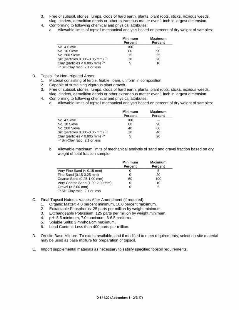
3. Free of subsoil, stones, lumps, clods of hard earth, plants, plant roots, sticks, noxious weeds, slag, cinders, demolition debris or other extraneous matter over 1 inch in largest dimension.
4. Conforming to following chemical and physical attributes: a. Allowable limits of topsoil mechanical analysis based on percent of dry weight of samples:
Minimum
Percent Maximum Percent
No. 4 Sieve 100 --- No. 10 Sieve 80 90 No. 200 Sieve 15 25 Silt (particles 0.005-0.05 mm) (1) 10 20 Clay (particles < 0.005 mm) (1) 5 10 (1) Silt-Clay ratio: 2:1 or less
B. Topsoil for Non-Irrigated Areas:
1. Material consisting of fertile, friable, loam, uniform in composition. 2. Capable of sustaining vigorous plant growth. 3. Free of subsoil, stones, lumps, clods of hard earth, plants, plant roots, sticks, noxious weeds,
slag, cinders, demolition debris or other extraneous matter over 1 inch in largest dimension. 4. Conforming to following chemical and physical attributes:
a. Allowable limits of topsoil mechanical analysis based on percent of dry weight of samples:
Minimum Percent
Maximum Percent
No. 4 Sieve 100 --- No. 10 Sieve 80 90 No. 200 Sieve 40 60 Silt (particles 0.005-0.05 mm) (1) 10 40 Clay (particles < 0.005 mm) (1) 5 20 (1) Silt-Clay ratio: 2:1 or less
b. Allowable maximum limits of mechanical analysis of sand and gravel fraction based on dry
weight of total fraction sample:
Minimum Percent
Maximum Percent
Very Fine Sand (< 0.15 mm) 0 5 Fine Sand (0.15-0.25 mm) 0 20 Coarse Sand (0.25-1.00 mm) 60 100 Very Coarse Sand (1.00-2.00 mm) 0 10 Gravel (> 2.00 mm) 0 5 (1) Silt-Clay ratio: 2:1 or less
C. Final Topsoil Nutrient Values After Amendment (if required):
1. Organic Matter: 4.0 percent minimum, 10.0 percent maximum. 2. Extractable Phosphorus: 25 parts per million by weight minimum. 3. Exchangeable Potassium: 125 parts per million by weight minimum. 4. pH: 5.5 minimum, 7.0 maximum, 6-6.5 preferred. 5. Soluble Salts: 3 mmhos/cm maximum. 6. Lead Content: Less than 400 parts per million.
D. On-site Base Mixture: To extent available, and if modified to meet requirements, select on-site material
may be used as base mixture for preparation of topsoil.
E. Import supplemental materials as necessary to satisfy specified topsoil requirements.
D-841.20 (Addendum 1 - 2/9/17)

PART 3 EXECUTION
3.01 EXAMINATION
A. Examine areas and conditions under which topsoil preparation and placement are to be performed. 1. Verify final subgrade has been established. 2. Verify topsoil meets requirements of this Section and soils testing lab report identifying required
amendments is completed. 3. Verify compaction requirements in Section 31 22 20 have not been exceeded.
B. Discrepancies:
1. Immediately notify Engineer. 2. Do not proceed in areas of discrepancy until fully resolved. 3. Commencement of topsoil placement signifies acceptance of surface conditions. Do not proceed
until unsatisfactory conditions have been corrected. 3.02 STORAGE/STOCKPILE
A. Stockpile location: As directed by Engineer.
B. Stockpile topsoil/planter soil component materials in such a manner that natural drainage is not obstructed and that no off-site sediment transmission will result.
C. Place stockpiles with maximum 2:1 sideslopes.
D. Construct a temporary perimeter dike with gravel outlet, or fabric sediment barrier around topsoil
component stockpiles.
E. Provide temporary seeding of stockpiles within 2 days of formation of stockpile.
F. Place mulch per Section 32 92 00. 3.03 PREPARATION AND PLACEMENT
A. Topsoil Placement Preparation: 1. Provide erosion and sediment control items such as diversions, berms, dikes, waterways,
sediment basins, as specified or as needed. 2. Remove debris from areas to be topsoiled, including excess concrete and concrete spoils
adjacent to back of curb locations, and excavation spoils. 3. Eliminate uneven areas and low spots; maintain indicated grades and make changes in grade
gradual by blending slopes into more level areas. 4. After the areas to be topsoiled have been brought to inferred subgrade elevations, and
immediately prior to dumping and spreading approved topsoil, loosen and condition the subgrade by power rototilling to a minimum depth of 8 inches to ensure removal of gross subgrade debris and bonding of the topsoil and subsoil; no substitute operations acceptable.
5. After rototilling and prior to placement of the topsoil, scalp or otherwise remove all visible stones, clods of hard earth, roots, plant parts, stumps, sticks, weeds, demolition or construction debris, or any other extraneous non-earth material in excess of 1 inch in size.
B. Topsoil Placement:
1. Do not place topsoil more than 2 weeks prior to planned commencement of Project planting operations.
2. Do not place wet or muddy topsoil, when subgrade is excessively wet, or in condition that may otherwise be detrimental to subsequent Work.
3. Uniformly place approved topsoil material where indicated to minimum compacted depth of 6 inches on 3:1 on steeper slopes, minimum of 8 inches on flatter slopes, and at greater depths as indicated on Drawings.
4. Topsoil in excess of 8 inches is acceptable and desirable if excess is available.
D-841.21 (Addendum 1 - 2/9/17)

5. Correct irregularities in surface resulting from placement or other operations to prevent formation of depressions or water pockets.
6. Avoid excessive compaction of topsoil; refer to limits in Section 31 22 20. 7. Protect topsoiled areas from weather based erosion until planting operations commence.
END OF SECTION
D-841.22 (Addendum 1 - 2/9/17)

SECTION 32 92 00
LAWNS AND GRASSES
PART 1 GENERAL
1.01 SUMMARY
A. Provide the following: 1. Seeding. 2. Sodding. 3. Plugging. 4. Sprigging. 5. Native Plantings: Meadow grasses and wildflowers. 6. Lawn renovation. 7. Accessories including, but not limited to:
a. Weed barrier. b. Landscape rock. c. Mulch. d. Landscape woodwork. e. Precast concrete splash blocks.
B. Perform the following:
1. Finish grading. (see Section 31 22 20) 2. Preparation of topsoil. 3. Initial maintenance.
C. Related Sections:
1. Section 31 22 20 - Earthwork for Building Sites 2. Section 31 25 10 - Temporary Erosion Control
1.02 REFERENCES
A. ASTM: 1. C602 - Standard for Agricultural Liming Materials 2. D5268 - Standard for Topsoil Used for Landscaping Purposes
B. TPI - Guideline Specifications to Turfgrass Sodding
1.03 SUBMITTALS
A. Refer to Section 01 33 00.
B. Product Data: 1. For each type of product indicated.
C. Certification of Grass Seed: From seed vendor for each grass seed, including:
1. Botanical and common name and percentage by weight of each species and variety. 2. Percentage of purity, germination, and weed seed. 3. Year of production and date of packaging. 4. Local source of seed mixture, including name and telephone number of supplier.
D. Qualification Data: For landscape installer.
D-841.23 (Addendum 1 - 2/9/17)

E. Planting Schedule: Proposed planting schedule, indicating dates for each type of landscape work during normal seasons for such work in area of site. Correlate with specified maintenance periods to provide maintenance from date of substantial completion. Once accepted, revise dates only as approved in writing, after documentation of reasons for delays.
F. Maintenance Instructions: Recommended procedures to be established by Owner for maintenance of
lawns and meadows during a calendar year. Submit before expiration of required maintenance periods.
1.04 QUALITY ASSURANCE
A. Qualifications: 1. Installer: A qualified landscape installer whose work has resulted in successful lawn and meadow
establishment. 2. Field Supervisor: Installer to maintain an experienced full-time supervisor on Site when planting is
in progress. 3. Soil Testing Laboratory: An independent laboratory recognized by the State DOA.
B. Topsoil Analysis:
1. Furnish soil analysis by qualified soil-testing laboratory stating percentages of organic matter, gradation of sand, silt and clay content; cation exchange capacity; deleterious material; pH; and mineral and plant-nutrient content of topsoil.
2. Report suitability of topsoil for plant growth. State recommended quantities of nitrogen, phosphorus, and potash nutrients and soil amendments to be added to produce a satisfactory topsoil.
C. Substitutions: Do not make substitutions. If specified landscape material is not obtainable, submit
proof of non-availability to Architect, together with proposal for use of equivalent material.
D. Preinstallation Meetings: If requested, the installer shall meet with Architect and landscaping supplier’s representative prior to the start of installation.
1.05 DELIVERY, STORAGE, AND HANDLING
A. Seed: Deliver in original sealed, labeled, and undamaged containers.
B. Sod: Harvest, deliver, store, and handle according to requirements in TPI’s “Specifications for Turfgrass Sod Materials” and “Specifications for Turfgrass Sod Transplanting and Installation” in its “Guideline Specifications to Turfgrass Sodding.” 1. Time delivery so that sod will be placed within 24 hours after stripping. 2. Protect sod against drying and breaking of rolled strips.
1.06 PROJECT CONDITIONS
A. Existing Conditions: 1. Inspect the Project prior to installation; 2. If conditions do not meet approval, notify Architect. 3. Proceeding without notification implies acceptance of conditions.
B. Excavation: When conditions detrimental to plant growth are encountered, such as rubble fill, adverse
drainage conditions, or obstructions, notify Architect before planting. 1.07 SEQUENCING AND SCHEDULING
A. Planting Time: Proceed with, and complete landscape work as rapidly as portions of site become available, working within seasonal limitations for each kind of landscape work required: 1. Plant or install materials during normal planting seasons for each type of plant material required.
D-841.24 (Addendum 1 - 2/9/17)

2. Correlate planting with specified maintenance periods to provide maintenance from date of Substantial Completion.
1.08 WARRANTY
A. Warranty for a period of 1 year after date of substantial completion against defects, including death and unsatisfactory growth, except for defects resulting from neglect by Owner, abuse or damage by others, or unusual phenomena or incidents which are beyond landscape installer’s control.
B. Replacement: Remove and replace lawns and grasses found to be dead or in unhealthy condition
during warranty period. 1.09 LAWN MAINTENANCE
A. Begin maintenance immediately after each area is planted and continue until acceptable lawn is established, but for not less than the following periods: 1. Seeded Lawns:
a. 60 days from date of Substantial Completion. b. When full maintenance period has not elapsed before end of planting season, or if lawn is
not fully established, continue maintenance during next planting season. 2. Sodded Lawns: 30 days from date of Substantial Completion. 3. Plugged Lawns: 30 days from date of Substantial Completion. 4. Sprigged Lawns: 30 days from date of Substantial Completion.
B. Maintain and establish lawn by watering, fertilizing, weeding, mowing, trimming, replanting, and other
operations. 1. Roll, regrade, and replant bare or eroded areas and remulch to produce a uniformly smooth lawn. 2. In areas where mulch has been disturbed by wind or maintenance operations, add new mulch. 3. Anchor as required to prevent displacement.
C. Watering:
1. Provide and maintain temporary piping, hoses, and lawn-watering equipment to convey water from sources and to keep lawn uniformly moist to a depth of 4 inches.
2. Schedule watering to prevent wilting, puddling, erosion, and displacement of seed or mulch. 3. Lay out temporary watering system to avoid walking over muddy or newly planted areas. 4. Water lawn at a minimum rate of 1 inch per week. 5. Provide soil moisture gage and monitor to determine soil water retention. 6. Water appropriately. Do not overwater.
D. Mowing:
1. Begin as soon as top growth is tall enough to cut. 2. Repeat mowing to maintain specified height without cutting more than 40 percent of grass height. 3. Remove no more than 40 percent of grass-leaf growth in initial or subsequent mowings. 4. Do not delay mowing until grass blades bend over and become matted. 5. Do not mow when grass is wet. 6. Schedule initial and subsequent mowings to maintain the following grass height:
a. Bentgrass: 1/2 inch high or less. b. Burmudagrass: 1/2 to 1 inch high. c. Carpetgrass, centipedegrass, perennial ryegrass, and zoysiagrass: 1 to 2 inches high. d. Kentucky bluegrass, buffalograss, annual ryegrass, and chewings red fescue: 2-1/2 to
4 inches high. e. Bahiagrass, turf-type tall fescue, and St. Augustine grass: 2 to 3 inches high.
E. Lawn Postfertilization:
1. Apply fertilizer after initial mowing and when grass is dry. 2. Use fertilizer that will provide actual nitrogen of at least 1 pound per 1000 square feet to lawn
area.
D-841.25 (Addendum 1 - 2/9/17)
1.10 MEADOW MAINTENANCE
A. Begin maintenance immediately after each area is planted and continue until acceptable meadow is established, but for not less than 60 days from date of Substantial Completion.
B. Maintain and establish meadow by watering, weeding, mowing, trimming, replanting, and other
operations.
C. Roll, regrade, and replant bare or eroded areas and remulch.
D. Watering: 1. Provide and maintain temporary piping, hoses, and lawn-watering equipment to convey water
from sources and to keep meadow uniformly moist. 2. Schedule watering to prevent wilting, puddling, erosion, and displacement of seed or mulch. 3. Lay out temporary watering system to avoid walking over muddy or newly planted areas. 4. Water meadow at a minimum rate of 1/2 inch per week for 8 weeks after planting, until well-
established.
E. Mowing: Single fall mowing to a height of 4 to 6 inches if landscape installer is required to maintain meadow during fall season.
PART 2 PRODUCTS
2.01 SOIL PREPARATION MATERIALS
A. Topsoil: 1. See Specification 32 91 00, for Topsoil testing requirements 2. Existing topsoil may be reused only with acceptance of Architect. 3. ASTM D5268, pH range of 5.5 to 7. 4. Fertile, friable natural sandy loam, without admixture of subsoil material, obtained not more than
2 or 3 feet from top of deposit, from well-drained arable site. 5. Free from heavy alkaline soil, coarse sand, stones larger than 2 inches in diameter, lumps, sticks,
other foreign matter. 6. Supplement with imported or manufactured topsoil from off-site sources when quantities are
insufficient. a. Obtain topsoil displaced from naturally well-drained construction or mining sites where
topsoil occurs at least 4 inches deep. b. Do not obtain from agricultural land, bogs or marshes.
2.02 INORGANIC SOIL AMENDMENTS
A. Lime: 1. ASTM C602, agricultural limestone containing a minimum 80 percent calcium carbonate
equivalent and as follows: a. Class: Class T, with a minimum 99 percent passing through No. 8 sieve and a minimum
75 percent passing through No. 60 sieve. b. Class: Class O, with a minimum 95 percent passing through No. 8 sieve and a minimum
55 percent passing through No. 60 sieve. 2. Provide lime in form of dolomitic limestone.
B. Sulfur:
1. Granular, biodegradable, containing a minimum of 90 percent sulfur, with a minimum 99 percent passing through No. 6 sieve and a maximum 10 percent passing through No. 40 sieve.
2. Iron Sulfate: Granulated ferrous sulfate containing a minimum of 20 percent iron and 10 percent sulfur.
3. Aluminum Sulfate: Commercial grade, unadulterated.
D-841.26 (Addendum 1 - 2/9/17)
C. Perlite: Horticultural perlite, soil amendment grade.
D. Agricultural or Recycled Gypsum: Finely ground, containing a minimum of 90 percent calcium sulfate. Free of contaminants.
E. Sand: Clean, washed, natural or manufactured, free of toxic materials.
F. Diatomaceous Earth: Calcined, diatomaceous earth, 90 percent silica, with approximately 140 percent
water absorption capacity by weight.
G. Zeolites: Mineral clinoptilolite with at least 60 percent water absorption by weight. 2.03 ORGANIC SOIL AMENDMENTS
A. Compost: 1. Well-composted, stable, and weed-free organic matter. 2. pH range of 5.5 to 8. 3. Moisture content 35 to 55 percent by weight. 4. 100 percent passing through 1/2-inch sieve. 5. Soluble salt content of 5 to 10 decisiemens/m. 6. Not exceeding 0.5 percent inert contaminants and free of substances toxic to plantings; and as
follows: a. Organic Matter Content: 50 to 60 percent of dry weight. b. Feedstock: Agricultural, food, or industrial residuals; biosolids; yard trimmings; or source-
separated or compostable mixed solid waste. c. Peat: Sphagnum peat moss, partially decomposed, finely divided or granular texture, with a
pH range of 3.4 to 4.8.
B. Wood Derivatives: 1. Decomposed, nitrogen-treated sawdust, ground bark, or wood waste. 2. Of uniform texture, free of chips, stones, sticks, soil, or toxic materials. 3. In lieu of decomposed wood derivatives, mix partially decomposed wood derivatives with at least
0.15 pound of ammonium nitrate or 0.25 pound of ammonium sulfate per cubic foot of loose sawdust or ground bark.
C. Manure:
1. Well-rotted, unleached, stable or cattle manure containing not more than 25 percent by volume of straw, sawdust, or other bedding materials.
2. Free of toxic substances, stones, sticks, soil, weed seed, and material harmful to plant growth. 2.04 PLANTING ACCESSORIES
A. Selective Herbicides: EPA registered and approved, of type recommended by manufacturer for application.
B. Fertilizers:
1. Bonemeal: Commercial, raw or steamed, finely ground; a minimum of 1 percent nitrogen and 10 percent phosphoric acid.
2. Superphosphate: Commercial, phosphate mixture, soluble; a minimum of 20 percent available phosphoric acid.
3. Commercial Fertilizer: Commercial-grade complete fertilizer of neutral character, consisting of fast- and slow-release nitrogen, 50 percent derived from natural organic sources of urea formaldehyde, phosphorous, and potassium in the following composition: a. Composition: Nitrogen, phosphorous, and potassium in amounts recommended in soil reports
from a qualified soil-testing agency. 4. Slow-Release Fertilizer: Granular or pelleted fertilizer consisting of 50 percent water-insoluble
nitrogen, phosphorus, and potassium in the following composition: a. `Composition: Nitrogen, phosphorous, and potassium in amounts recommended in soil reports
from a qualified soil-testing agency.
D-841.27 (Addendum 1 - 2/9/17)

C. Mulches: 1. Straw Mulch: Provide air-dry, clean, mildew- and seed-free, salt hay or threshed straw of wheat,
rye, oats, or barley. 2. Peat Mulch: Sphagnum peat moss, partially decomposed, finely divided or granular texture, with
a pH range of 3.4 to 4.8. 3. Compost Mulch:
a. Well-composted, stable, and weed-free organic matter. b. pH range of 5.5 to 8. c. Moisture content 35 to 55 percent by weight. d. 100 percent passing through 1-inch sieve; soluble salt content of 5 to 10 decisiemens/m. e. Not exceeding 0.5 percent inert contaminants and free of substances toxic to plantings; and
as follows: 1) Organic Matter Content: 50 to 60 percent of dry weight. 2) Feedstock: Agricultural, food, or industrial residuals; biosolids; yard trimmings; or
source-separated or compostable mixed solid waste. 4. Fiber Mulch: Hardwood shredded mulch.
D. Weed Barrier:
1. 6-mil black polyethylene film. 2. Environmentally-responsible projects: Use cellulosic mulch.
a. 60 to 100 percent post-consumer recycled content shredded paper or newspaper. 2.05 EROSION-CONTROL MATERIALS
A. Erosion-Control Blankets: 1. Biodegradable wood excelsior, straw, or coconut-fiber mat enclosed in a photodegradable plastic
mesh. 2. Acceptable manufacturer and product:
a. SI Geosolutions, LandLok Series, applicable format. b. RoLanka Erosion Control Mats. c. Comparable products of other manufacturer.
3. Include manufacturer’s recommended steel wire staples, 6 inches long.
B. Erosion-Control Fiber Mesh: 1. Biodegradable twisted jute or spun-coir mesh. 2. A minimum of 0.92 pound/square yard, with 50 to 65 percent open area. 3. Acceptable Manufacturer and Product:
a. SI Geosolutions, LandLok Series, applicable format. b. RoLanka Erosion Control Mats. c. Comparable products of other manufacturer.
4. Include manufacturer’s recommended steel wire staples, 6 inches long. 2.06 LAWNS AND GRASSES
A. Seed: 1. Products: First line product of Scott, Northrup King, or accepted equal. 2. Seed: Fresh clean “new crop” seed, 85 to 95 percent germination, free of noxious weed seeds,
recleaned, treated with appropriate fungicide at time of mixing. 3. Lawn Mixture: Types and proportions of seeds recommended for climate and conditions,
containing minimum 60 percent Kentucky Bluegrass, 30 percent Creeping Red Fescue, maximum 1 percent weed seed, 3.1 percent inert matter.
B. Sod:
1. Provide strongly rooted sod, not less than 2 years old. a. Free of weeds and undesirable plants, large stones, other material that might be detrimental
to development of sod or future maintenance. b. Capable of vigorous growth and development when planted (viable, not dormant).
D-841.28 (Addendum 1 - 2/9/17)
2. Pads: a. Provide uniform pad sizes with maximum 5 percent deviation in either length or width. b. Machine cut to pad thickness of 3/4 inch (plus or minus 1/4 inch), excluding top growth and
thatch. c. Broken pads or pads with uneven ends will not be acceptable. d. Sod pads incapable of supporting their own weight when suspended vertically with a firm
grasp on upper 10 percent of pad will be rejected. 3. Content: Minimum 70 percent Kentucky Blue Grass.
C. Meadow Grasses and Wildflowers:
1. Native Grass Seed: a. Fresh, clean, dry, new seed. b. Species mix: Per Drawings
2. Seed Carrier: a. Inert material, sharp clean sand or perlite. b. Mix with seed at a ratio of not less than 2 parts seed carrier to 1 part seed.
PART 3 EXECUTION
3.01 PREPARATION
A. Planting Soil: 1. Subsoil:
a. After subgrade is established and accepted, loosen to depth of minimum 4 inches. b. Remove sticks, stones, roots and rubbish. c. Smooth over to remove ridges and depressions so surface is parallel to finished grade.
2. Topsoil: a. Before mixing, clean topsoil of roots, plants, sods, stones, clay lumps, and other extraneous
materials harmful or toxic to plant growth. b. Do not turn existing vegetation over into soil being prepared for lawns.
3. Soil Amendments: a. Mix Lime with dry soil prior to mixing of fertilizer; prevent lime from contacting roots of acid-
loving plants. b. Apply phosphoric acid fertilizer (other than that constituting a portion of complete fertilizers)
directly to subgrade before applying planting soil and tilling. c. Mix specified soil amendments and fertilizers with topsoil at rates specified. d. Delay mixing of fertilizer if planting will not follow placing of planting soil within a few days.
B. Lawns and Grasses:
1. Prepare subsoil and lawn areas just prior to actual seeding. 2. Place approximately 1/2 of total amount of topsoil required. 3. Work into top of loosened subgrade to create a transition layer and then place remainder of
planting soil. 4. Add specified soil amendments and mix thoroughly into upper 4 inches of topsoil. 5. Unchanged Grades: Where lawns are to be planted in areas that have not been altered or
disturbed by excavating, grading, or stripping operations, prepare soil for lawn planting as follows: a. Till to a depth of not less than 6 inches. b. Apply soil amendments and initial fertilizers as specified. c. Remove high areas and fill in depressions. d. Till soil to a homogenous mixture of fine texture, free of lumps, clods, stones, roots and other
extraneous matter. e. If undisturbed areas contain grass or turf, prior to preparation of unchanged areas remove
existing grass, vegetation and turf. 6. Allow for sod thickness in areas to be sodded. 7. Apply specified commercial fertilizer at rates specified and thoroughly mix into upper 2 inches of
topsoil. Delay application of fertilizer if lawn planting will not follow within a few days. 8. Fine grade lawn areas to smooth, even surface with loose, uniformly fine texture.
D-841.29 (Addendum 1 - 2/9/17)

9. Roll, rake, and drag lawn areas, remove ridges and fill depressions, as required to meet finish grades.
10. Limit fine grading to areas which can be planted immediately after grading. 11. Moisten prepared lawn areas before planting if soil is dry.
a. Water thoroughly and allow surface moisture to dry before planting lawns. b. Do not create a muddy soil condition.
12. Restore lawn areas to specified condition, if eroded or otherwise disturbed, after fine grading and prior to planting.
3.02 LAWNS AND GRASSES
A. Seeding New Lawns: 1. Seed at time favorable to growth of grass, only at time acceptable to Architect. 2. Do not seed after rain unless ground surface thoroughly loosened. 3. Do not seed when wind velocity exceeds 5 miles per hour. 4. Do not use wet seed or seed that is moldy or otherwise damaged in transit or storage. 5. Sow seed using a spreader or seeding machine. 6. Distribute seed evenly over entire area by sowing equal quantity in 2 directions at right angles to
each other. 7. Sow not less than one pound of seed per 150 square feet. 8. Rake seed lightly into top 1/8 inch of soil, roll lightly, and water with a fine spray. 9. Protect seeded slopes against erosion.
B. Hydroseeding New Lawns:
1. Mix specified seed, fertilizer, and pulverized mulch in water, using equipment specifically designed for hydroseed application.
2. Continue mixing until uniformly blended into homogenous slurry suitable for hydraulic application. 3. Mix slurry with tackifier. 4. Apply slurry uniformly to all areas to be seeded. 5. Rate of application as required to obtain specified seed sowing rate.
C. Sodding New Lawns:
1. Lay sod within 24 hours from time of stripping. 2. Do not plant dormant sod or if ground is frozen. 3. Lay sod to form a solid mass with tightly fitted joints. 4. Butt ends and sides of sod strips; do not stretch or overlap. 5. Stagger strips to offset joints in adjacent courses. 6. Work from boards to avoid damage to subgrade or sod. 7. Tamp or roll lightly to ensure contact with subgrade, eliminate air pockets, and form a smooth
surface. 8. Work sifted soil into minor cracks between pieces of sod; remove excess to avoid smothering of
adjacent grass. 9. Anchor sod on slopes with wood pegs to prevent slippage. 10. Water sod thoroughly with a fine spray immediately after planting. 11. During first week, water daily or more frequently as necessary to maintain moist soil to a
minimum depth of 1-1/2 inches.
D. Reconditioning Existing Lawns: 1. Recondition existing lawn areas damaged by Contractor’s operations including storage of
materials and equipment and movement of vehicles. 2. Recondition existing lawn areas where minor regrading is required. 3. Provide new topsoil, as required, to fill low spots and meet new finish grades. 4. Till bare and compacted areas thoroughly to provide a satisfactory planting bed. 5. Remove sod and vegetation from diseased or unsatisfactory lawn areas; do not bury in soil. 6. Remove topsoil containing foreign materials resulting from Contractor’s operations, including oil
drippings, fuel spills, stone, gravel, and other construction materials, and replace with new topsoil. 7. Mow, dethatch, core aerate, and rake existing lawn. 8. Remove weeds before seeding. If extensive, apply herbicides. Do not use pre-emergence
herbicides.
D-841.30 (Addendum 1 - 2/9/17)

9. Apply seed or sod as required for new lawns. 10. Water newly planted lawn areas and keep moist until new grass is established.
3.03 MEADOW
A. Sowing: 1. Use spreader or seeding machine. 2. Do not broadcast or drop seed when wind velocity exceeds 5 mph. 3. Evenly distribute seed by sowing equal quantities in 2 directions at right angles to each other. 4. Do not use wet seed or seed that is moldy or otherwise damaged. 5. Sow seed at the net rate of 6 ounces per 1000 square feet. 6. Brush seed into top 1/16 inch of topsoil, roll lightly, and water with fine spray. 7. Water newly planted areas and keep moist until meadow is established.
3.04 MISCELLANEOUS LANDSCAPE WORK
A. Weed Barrier: Lay film continuously over compacted subgrade prior to placing gravel. Overlap edges 4 inches at joints between sheets.
B. Woodchip Mulch: Install to depth shown on drawings, or if not shown, 2 inches.
C. Landscape Woodwork:
1. Install wood headers and edgings where indicated. 2. Anchor with wood stakes spaced not more than 3 feet on center, and driven at least 1 inch below
top elevation of header or edging. 3. Use 2 galvanized nails per stake to fasten headers and edging, and clinch point of each nail.
D. Placing Erosion Mats:
1. Place immediately after mulch or sod has been placed. 2. Overlap adjacent strips between 2 inches and 4 inches with upstream strip placed on top. 3. Secure netting with wire staples, place 2 to 3 feet apart.
E. Placing Wood Fiber Blanket:
1. Place within 24 hours after seeding. 2. Overlap strip ends 10 inches minimum with upgrade strip on top. 3. Bury upgrade end of each strip minimum 6 inches into soil. 4. Secure with wire staples placed at maximum 3-foot spacing.
F. Splash block: Install where indicated on Drawings.
3.05 CLEANUP, MAINTENANCE, AND PROTECTION
A. During landscape work, keep pavements clean and work area in an orderly condition.
B. Promptly remove soil and debris created by lawn work from paved areas.
C. Clean wheels of vehicles before leaving site to avoid tracking soil onto roads, walks, or other paved areas.
D. Erect barricades and warning signs as required to protect newly planted areas from traffic. Maintain
barricades throughout maintenance period and remove after lawn is established.
E. Remove erosion-control measures after grass establishment period.
F. Disposal: 1. Remove waste and foreign materials, including weeds, stones, soil cores, grass, vegetation, and
sod and legally dispose of them off Owner’s property. 2. Divert from landfill disposal whenever possible.
D-841.31 (Addendum 1 - 2/9/17)

3. Topsoil containing foreign materials resulting from Contractor’s operations, including oil drippings, fuel spills, shall be disposed of legally.
3.06 INSPECTION AND ACCEPTANCE
A. Inspection: Landscape work may be inspected for acceptance in portions as agreeable to Architect, provided each portion of work offered for inspection is complete, including maintenance.
B. Rejected Work: When inspected landscape work does not comply with requirements, replace rejected
work and continue specified maintenance until reinspected by Architect and found to be acceptable.
END OF SECTION
D-841.32 (Addendum 1 - 2/9/17)
SECTION 32 92 12
TURF ESTABLISHMENT
PART 1 GENERAL
1.01 SUMMARY
A. Section includes establishment of herbaceous ground cover on designated areas.
B. Related Sections: 1. Section 31 23 30 - Excavation, Backfilling and Compacting 2. Section 31 25 10 - Temporary Erosion Control
C. Method of Measurement: Measured by lump sum including all necessary equipment, material and
labor to complete the bid item as shown on the Drawings and Project Manual.
D. Basis of Payment: Payment shall be at the contract lump sum price. All work items shall be considered incidental.
1.02 REFERENCES
A. WisDOT - Standard Specifications for Highway and Structure Construction: 1. 625 - Topsoil and Salvaged Topsoil 2. 627 - Mulching 3. 629 - Fertilizer and Agricultural Limestone 4. 630 - Seeding
1.03 SUBMITTALS
A. Submit certified test report for each seed mixture. 1.04 ACCEPTANCE OF WORK
A. Turf establishment will be accepted on a total project basis.
B. All erosion control items must also be in place and properly maintained prior to acceptance.
C. Once accepted, Contractor is relieved of any further maintenance or repair. 1.05 DELIVERY, STORAGE, AND HANDLING
A. Protect seed from moisture, heat, rodents, and other damage prior to use.
B. Deliver fertilizer in waterproof bags showing weight, chemical analysis and name of manufacturer. 1.06 SCHEDULE OF WORK
A. Coordinate turf establishment to minimize lag time after topsoil placement.
B. Plant seed between May 1 and September 20. 1.07 MAINTENANCE
A. Maintain and repair all areas until acceptance.
D-841.33 (Addendum 1 - 2/9/17)

B. Contractor shall apply water as needed in accordance with the requirements of WisDOT 631.3.5. PART 2 PRODUCTS
2.01 MATERIALS
A. Topsoil: WisDOT 625.2.
B. Mulch: WisDOT 627.
C. Fertilizer: WisDOT 629, Type B.
D. Seed: WisDOT 630.2.1.5. PART 3 EXECUTION
3.01 SOIL PREPARATIONS
A. Remove all undesirable weeds as directed.
B. Loosen topsoil on all areas with 2:1 slopes or flatter prior to seeding.
C. Cultivate to a depth of 3 inches using discs or other suitable equipment.
D. Operate equipment at right angles to direction of drainage.
E. Fill all washouts prior to cultivation.
F. Finish all areas to provide a smooth, moist, even-textured foundation of uniform density.
G. Approval of the Engineer is required prior to placing seed. 3.02 CONSTRUCTION REQUIREMENTS
A. Applying Fertilizer and Conditioners: 1. Apply fertilizer uniformly over the designated area using mechanical spreading devices. 2. Apply at a rate of 7 pounds per 1,000 square feet. 3. Apply fertilizer no more than 48 hours prior to seeding.
B. Sowing Seed:
1. Apply seed mixture 10 and 30 over designated areas at a rate of 1.5 pounds per 1,000 square feet for each mixture for a total rate of 3 pounds per 1,000 square feet.
2. Apply seed uniformly by mechanical or hydrospreading method. 3. Firm all seeded areas with a drag or cultipacker immediately after seeding and prior to mulching.
END OF SECTION
D-841.34 (Addendum 1 - 2/9/17)

SECTION 32 93 00
EXTERIOR PLANTS
PART 1 GENERAL
1.01 SUMMARY
A. Section Includes: 1. Trees. 2. Shrubs. 3. Perennials. 4. Plants and bulbs. 5. Landscape accessories including, but not limited to:
a. Weed barrier. b. Mulch. c. Edging. d. Wrapping. e. Stakes and guys.
B. Perform the following:
1. Finish grading. (Section 31 22 20) 2. Preparation of topsoil. 3. Plant installation. 4. Initial maintenance of landscape materials. 5. Pruning and relocation of existing plant materials.
C. Related Sections:
1. Section 31 11 00 - Clearing and Grubbing 2. Section 31 22 20 - Earthwork for Building Sites
D. Basis of Payment:
1. All materials and labor necessary for the installation of all plant material shall be measured and paid for as a unit price, listed on Bid Form.
2. All materials and labor necessary for the installation of mulch in planting beds shall be measured and paid for as a unit price, listed on Bid Form. All other mulch is incidental to the Unit Price Bid of the plants.
3. All materials and labor necessary for the installation of edging at planting beds shall be measured and paid for as a unit price, listed on Bid Form.
4. Fertilizer, compost, protective materials, and other specified materials are incidental to the Unit Price Bid of the plants.
1.02 REFERENCES
A. ANSI : 1. 60.1 - American Standard for Nursery Stock
B. ASTM:
1. C602 - Standard for Agricultural Liming Materials 2. D5268 - Standard for Topsoil Used for Landscaping Purposes
C. USCC - The US Composting Council
1.03 SUBMITTALS
A. Refer to Section 01 33 00.
D-841.35 (Addendum 1 - 2/9/17)
B. Product Data: For each type of product indicated.
C. Samples for Verification: 1. 5 pounds of mineral mulch in labeled plastic bag. 2. Edging materials, accessories.
D. Plant and Material Certifications:
1. Certificates of inspection as required by governmental authorities. 2. Manufacturer’s or vendor’s certified analysis for soil amendments and fertilizer materials and
standard products. 3. Label data substantiating that plants, trees, shrubs and planting materials comply with specified
requirements.
E. Maintenance: Typed instructions recommending procedures to be established by Owner for maintenance of landscape work for 1 full year. Submit prior to expiration of required maintenance period.
F. Material Test Reports: Provide for existing surface soil and imported topsoil.
1.04 QUALITY ASSURANCE
A. Qualifications: 1. Installer: A qualified landscape installer whose work has resulted in successful plant and tree
establishment. 2. Field Supervisor: Installer to maintain an experienced full-time supervisor on Site when planting is
in progress. 3. Soil Testing Laboratory: An independent laboratory recognized by the State DOA.
B. Trees, Shrubs and Plants:
1. Measurements: a. Measure according to ANSI Z60.1 with branches and trunks or canes in their normal
position. b. Do not prune to obtain required sizes. c. Take caliper measurements 6 inches above ground for trees up to 4-inch caliper size and
12 inches above ground for larger sizes. d. Measure main body of tree or shrub for height and spread. e. Do not measure branches or roots tip-to-tip.
2. Labeling: a. Label each tree and shrub with securely attached waterproof tag bearing legible designation
of botanical and common name. b. Where formal arrangements or consecutive order of trees or shrubs are shown, select stock
for uniform height and spread, and label with number to assure symmetry in planting.
C. Observation: 1. Engineer may observe trees and shrubs either at place of growth or at Site before planting, for
compliance with requirements for genus, species, variety, size, and quality. 2. Engineer retains right to further inspect trees and shrubs for size and condition of balls and root
systems, insects, injuries and latent defects, and to reject unsatisfactory or defective material at any time during progress of Work.
3. Remove rejected trees or shrubs immediately from Site.
D. Topsoil Analysis: 1. Furnish soil analysis by qualified soil-testing laboratory stating percentages of organic matter,
gradation of sand, silt and clay content; cation exchange capacity; deleterious material; pH; and mineral and plant-nutrient content of topsoil.
2. Report suitability of topsoil for plant growth. State recommended quantities of nitrogen, phosphorus, and potash nutrients and soil amendments to be added to produce a satisfactory topsoil.
D-841.36 (Addendum 1 - 2/9/17)
E. Preinstallation Meetings: If requested, installer shall meet with Engineer and landscaping supplier’s representative prior to the start of installation.
1.05 DELIVERY, STORAGE, AND HANDLING
A. Deliver trees and shrubs after preparations for planting have been completed and plant immediately.
B. Deliver packaged materials in containers showing weight, analysis, and name of manufacturer.
C. Trees and Shrubs: 1. Protect bark, branches, and root systems from sun scald, drying, sweating, whipping, and other
handling and tying damage. 2. Balled and Burlapped Stock:
a. Do not drop during delivery. b. Handle planting stock by root ball. c. Set on ground and cover with soil, peat moss, sawdust, or other acceptable material.
3. Bare Root Stock: a. Immediately after digging up, pack root system in wet straw, hay, or other suitable material
to keep root system moist until planting. b. Soak roots in water for 2 hours if dried out.
4. Container-grown Stock: Do not remove container-grown stock from containers until planting time. 5. Water root systems of plants stored on-site with a fine-mist spray as often as necessary to
maintain in a moist condition. 6. If planting is delayed more than 6 hours after delivery, set trees and plants in shade, protect from
weather and mechanical damage, and keep roots moist by covering with mulch, burlap or other acceptable means of retaining moisture.
D. Bulbs:
1. Keep dormant bulbs dry and protected. 2. Keep disease-free.
E. Annuals:
1. Keep well watered and in a protected location. 2. Do not remove annuals form containers until ready to plant.
1.06 PROJECT CONDITIONS
A. Existing Conditions: 1. Inspect the Site prior to installation. If conditions do not meet approval, notify Engineer. 2. Proceeding without notification implies acceptance of conditions.
B. Environmental: Work within seasonal limitations for each kind of landscape work required.
C. Utilities:
1. Determine location of underground utilities and perform work in a manner which will avoid possible damage.
2. Contact Diggers Hotline (811) at least 48 hours prior to conducting any underground operations. 3. Hand excavate, as required. 4. Maintain grade stakes set by others until removal is mutually agreed upon by parties concerned.
1.07 SEQUENCING AND SCHEDULING
A. Planting Time: Proceed with, and complete landscape work as rapidly as portions of Site become available, working within seasonal limitations for each kind of landscape work required: 1. Plant or install materials during normal planting seasons for each type of plant material required. 2. Correlate planting with specified maintenance periods to provide maintenance from date of
Substantial Completion.
D-841.37 (Addendum 1 - 2/9/17)
B. Coordination with Lawns: 1. Plant trees and shrubs after final grades are established and prior to planting of lawns, unless
otherwise acceptable to Engineer. 2. If planting of trees and shrubs occurs after lawn work, protect lawn areas and promptly repair
damage to lawns resulting from planting operations. 1.08 WARRANTY
A. Trees, Shrubs and Perennials: Warranty for a period of 1 year after date of Substantial Completion, against defects including death and unsatisfactory growth, except for defects resulting from neglect by Owner, abuse or damage by others, or unusual phenomena or incidents which are beyond Landscape Installer’s control.
B. Replacement:
1. Remove and replace immediately trees, shrubs, or other plants found to be dead or in unhealthy condition.
2. Replace immediately unless required to plant in succeeding planting season. 3. Replace exterior plants that are more than 25 percent dead or in an unhealthy condition at end of
warranty period. 4. A limit of 1 replacement of each exterior plant will be required, except for losses or replacements
due to failure to comply with requirements. 1.09 MAINTENANCE
A. Trees and Shrubs: 1. Maintain for 12 months from date of Substantial Completion. 2. Prune, cultivate, water, weed, fertilize, restore planting saucers, tighten and repair stakes and guy
supports, and reset to proper grades or vertical position, as required to establish healthy, viable plantings.
3. Spray as required to keep trees and shrubs free of insects and disease. 4. Restore or replace damaged tree wrappings.
B. Perennials and Bulbs:
1. Maintain for 12 months from date of Substantial Completion. 2. Water, weed, fertilize, and perform other operations as required to establish healthy, viable
plantings. PART 2 PRODUCTS
2.01 SOIL PREPARATION MATERIALS
A. Topsoil: 1. See Specification 32 91 00, for Topsoil requirements 2. Native topsoil stockpiled on Site or existing topsoil may be reused only with acceptance of
Engineer. 3. ASTM D5268, pH range of 5.5 to 7. 4. Fertile, friable natural sandy loam, without admixture of subsoil material, obtained not more than
2 or 3 feet from top of deposit, from well-drained arable site. 5. Free from heavy alkaline soil, coarse sand, stones larger than 2 inches in diameter, lumps, sticks,
other foreign matter. 6. Supplement with imported or manufactured topsoil from off-site sources when quantities are
insufficient. a. Obtain topsoil displaced from naturally well-drained construction or mining sites where
topsoil occurs at least 4 inches deep. b. Do not obtain from agricultural land, bogs, or marshes.
D-841.38 (Addendum 1 - 2/9/17)
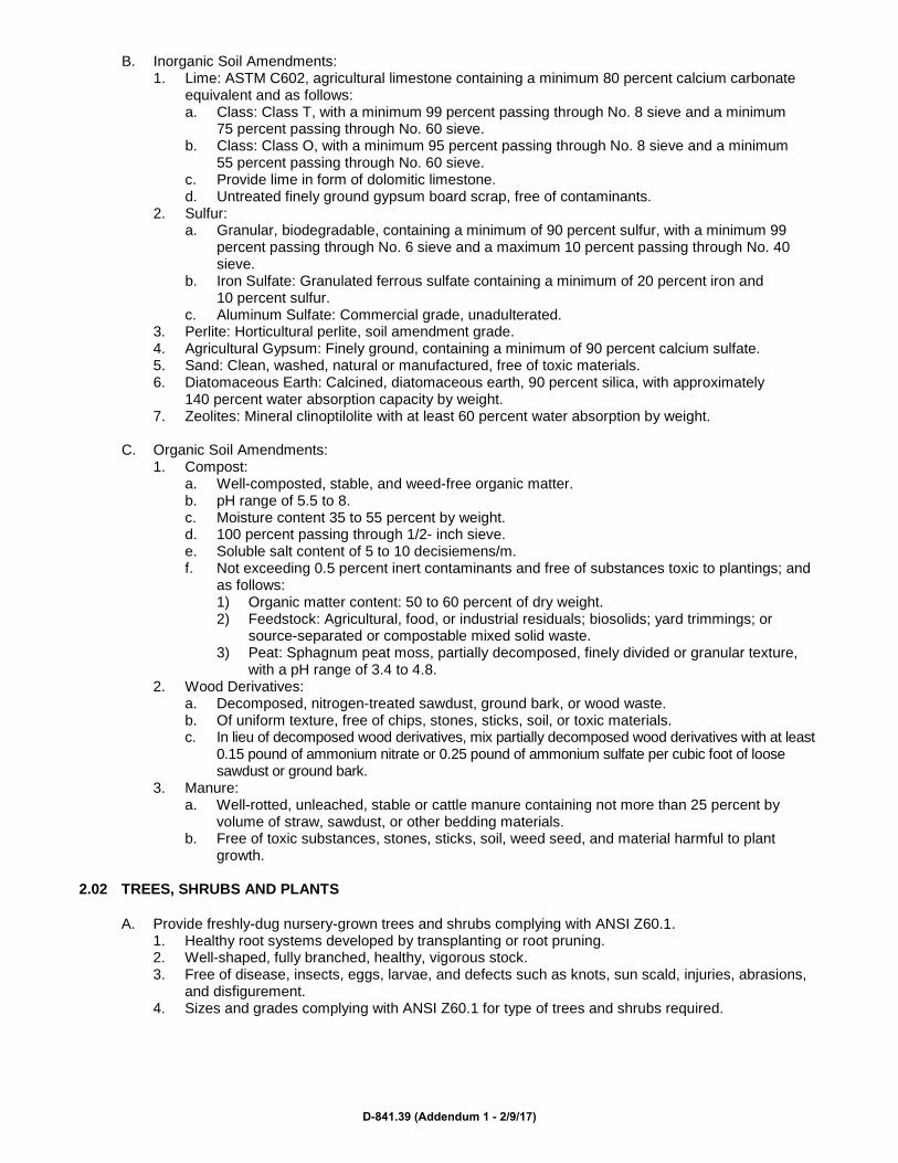
B. Inorganic Soil Amendments: 1. Lime: ASTM C602, agricultural limestone containing a minimum 80 percent calcium carbonate
equivalent and as follows: a. Class: Class T, with a minimum 99 percent passing through No. 8 sieve and a minimum
75 percent passing through No. 60 sieve. b. Class: Class O, with a minimum 95 percent passing through No. 8 sieve and a minimum
55 percent passing through No. 60 sieve. c. Provide lime in form of dolomitic limestone. d. Untreated finely ground gypsum board scrap, free of contaminants.
2. Sulfur: a. Granular, biodegradable, containing a minimum of 90 percent sulfur, with a minimum 99
percent passing through No. 6 sieve and a maximum 10 percent passing through No. 40 sieve.
b. Iron Sulfate: Granulated ferrous sulfate containing a minimum of 20 percent iron and 10 percent sulfur.
c. Aluminum Sulfate: Commercial grade, unadulterated. 3. Perlite: Horticultural perlite, soil amendment grade. 4. Agricultural Gypsum: Finely ground, containing a minimum of 90 percent calcium sulfate. 5. Sand: Clean, washed, natural or manufactured, free of toxic materials. 6. Diatomaceous Earth: Calcined, diatomaceous earth, 90 percent silica, with approximately
140 percent water absorption capacity by weight. 7. Zeolites: Mineral clinoptilolite with at least 60 percent water absorption by weight.
C. Organic Soil Amendments:
1. Compost: a. Well-composted, stable, and weed-free organic matter. b. pH range of 5.5 to 8. c. Moisture content 35 to 55 percent by weight. d. 100 percent passing through 1/2- inch sieve. e. Soluble salt content of 5 to 10 decisiemens/m. f. Not exceeding 0.5 percent inert contaminants and free of substances toxic to plantings; and
as follows: 1) Organic matter content: 50 to 60 percent of dry weight. 2) Feedstock: Agricultural, food, or industrial residuals; biosolids; yard trimmings; or
source-separated or compostable mixed solid waste. 3) Peat: Sphagnum peat moss, partially decomposed, finely divided or granular texture,
with a pH range of 3.4 to 4.8. 2. Wood Derivatives:
a. Decomposed, nitrogen-treated sawdust, ground bark, or wood waste. b. Of uniform texture, free of chips, stones, sticks, soil, or toxic materials. c. In lieu of decomposed wood derivatives, mix partially decomposed wood derivatives with at least
0.15 pound of ammonium nitrate or 0.25 pound of ammonium sulfate per cubic foot of loose sawdust or ground bark.
3. Manure: a. Well-rotted, unleached, stable or cattle manure containing not more than 25 percent by
volume of straw, sawdust, or other bedding materials. b. Free of toxic substances, stones, sticks, soil, weed seed, and material harmful to plant
growth. 2.02 TREES, SHRUBS AND PLANTS
A. Provide freshly-dug nursery-grown trees and shrubs complying with ANSI Z60.1. 1. Healthy root systems developed by transplanting or root pruning. 2. Well-shaped, fully branched, healthy, vigorous stock. 3. Free of disease, insects, eggs, larvae, and defects such as knots, sun scald, injuries, abrasions,
and disfigurement. 4. Sizes and grades complying with ANSI Z60.1 for type of trees and shrubs required.
D-841.39 (Addendum 1 - 2/9/17)
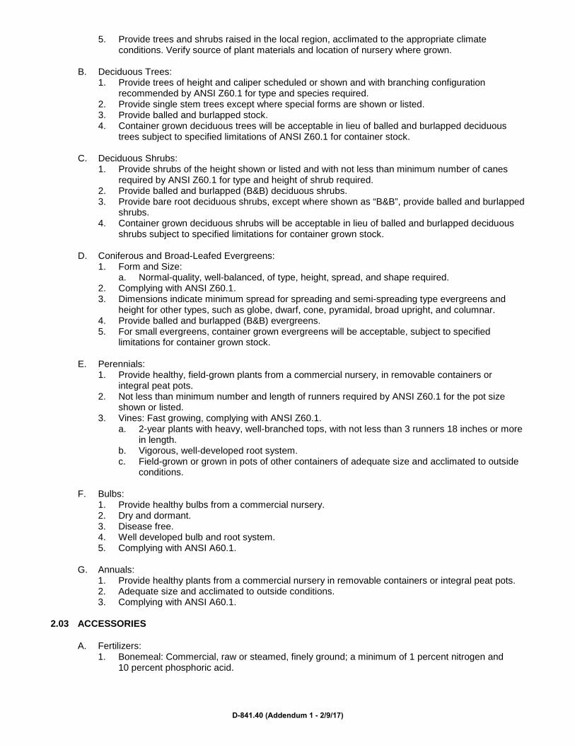
5. Provide trees and shrubs raised in the local region, acclimated to the appropriate climate conditions. Verify source of plant materials and location of nursery where grown.
B. Deciduous Trees:
1. Provide trees of height and caliper scheduled or shown and with branching configuration recommended by ANSI Z60.1 for type and species required.
2. Provide single stem trees except where special forms are shown or listed. 3. Provide balled and burlapped stock. 4. Container grown deciduous trees will be acceptable in lieu of balled and burlapped deciduous
trees subject to specified limitations of ANSI Z60.1 for container stock.
C. Deciduous Shrubs: 1. Provide shrubs of the height shown or listed and with not less than minimum number of canes
required by ANSI Z60.1 for type and height of shrub required. 2. Provide balled and burlapped (B&B) deciduous shrubs. 3. Provide bare root deciduous shrubs, except where shown as “B&B”, provide balled and burlapped
shrubs. 4. Container grown deciduous shrubs will be acceptable in lieu of balled and burlapped deciduous
shrubs subject to specified limitations for container grown stock.
D. Coniferous and Broad-Leafed Evergreens: 1. Form and Size:
a. Normal-quality, well-balanced, of type, height, spread, and shape required. 2. Complying with ANSI Z60.1. 3. Dimensions indicate minimum spread for spreading and semi-spreading type evergreens and
height for other types, such as globe, dwarf, cone, pyramidal, broad upright, and columnar. 4. Provide balled and burlapped (B&B) evergreens. 5. For small evergreens, container grown evergreens will be acceptable, subject to specified
limitations for container grown stock.
E. Perennials: 1. Provide healthy, field-grown plants from a commercial nursery, in removable containers or
integral peat pots. 2. Not less than minimum number and length of runners required by ANSI Z60.1 for the pot size
shown or listed. 3. Vines: Fast growing, complying with ANSI Z60.1.
a. 2-year plants with heavy, well-branched tops, with not less than 3 runners 18 inches or more in length.
b. Vigorous, well-developed root system. c. Field-grown or grown in pots of other containers of adequate size and acclimated to outside
conditions.
F. Bulbs: 1. Provide healthy bulbs from a commercial nursery. 2. Dry and dormant. 3. Disease free. 4. Well developed bulb and root system. 5. Complying with ANSI A60.1.
G. Annuals:
1. Provide healthy plants from a commercial nursery in removable containers or integral peat pots. 2. Adequate size and acclimated to outside conditions. 3. Complying with ANSI A60.1.
2.03 ACCESSORIES
A. Fertilizers: 1. Bonemeal: Commercial, raw or steamed, finely ground; a minimum of 1 percent nitrogen and
10 percent phosphoric acid.
D-841.40 (Addendum 1 - 2/9/17)

2. Superphosphate: Commercial, phosphate mixture, soluble; a minimum of 20 percent available phosphoric acid.
3. Commercial Fertilizer: Commercial-grade complete fertilizer of neutral character, consisting of fast- and slow-release nitrogen, 50 percent derived from natural organic sources of urea formaldehyde, phosphorous, and potassium in the following composition: a. Composition: Nitrogen, phosphorous, and potassium in amounts recommended in soil
reports from a qualified soil-testing agency. 4. Slow-Release Fertilizer: Granular or pelleted fertilizer consisting of 50 percent water-insoluble
nitrogen, phosphorus, and potassium in the following composition: a. Composition: Nitrogen, phosphorous, and potassium in amounts recommended in soil reports
from a qualified soil-testing agency.
B. Mulches: 1. Organic Mulch: Free from deleterious materials and suitable as a top dressing of trees and
shrubs. a. Shredded hardwood. b. Ground or shredded bark. c. Pine straw. d. Salt hay or threshed straw. e. Wood and bark chips. f. Pine needles. g. Peanut, pecan, and cocoa-bean shells.
2. Compost Mulch: a. Well-composted, stable, and weed-free organic matter. b. pH range of 5.5 to 8. c. Moisture content 35 to 55 percent by weight. d. 100 percent passing through 1-inch sieve; soluble salt content of 5 to 10 decisiemens/m. e. Not exceeding 0.5 percent inert contaminants and free of substances toxic to plantings; and
as follows: 1) Organic matter content: 50 to 60 percent of dry weight. 2) Feedstock: Agricultural, food, or industrial residuals; biosolids; yard trimmings; or
source-separated or compostable mixed solid waste.
C. Stakes and Guys: 1. Upright and Guy Stakes:
a. Wood: Rough-sawn, sound, free of knots, holes, cross grain, and other defects. b. Steel, tapered. c. Aluminum: ASTM B221, alloy 6061-T6. d. 2-inch by 2-inch by length indicated. e. Pointed at one end.
2. Guy and Tie Wire: a. ASTM A641/A, Class 1. b. Galvanized-steel wire. c. 2-strand, twisted. d. 0.106 inch diameter.
3. Guy Cable: a. 5-strand, 3/16-inch-diameter. b. Galvanized-steel cable with zinc-coated turnbuckles. c. Minimum of 3 inches long. d. Two 3/8-inch galvanized eyebolts.
4. Hose Chafing Guard: a. Reinforced rubber or plastic hose at least 1/2 inch in diameter. b. Black. c. Cut to lengths required to protect tree trunks from damage.
5. Flags: a. Standard surveyor’s plastic flagging tape. b. Color: White. c. Size: 6 inches long.
D-841.41 (Addendum 1 - 2/9/17)

2.04 MISCELLANEOUS PRODUCTS
A. Antidesiccant: 1. Water-insoluble emulsion, permeable moisture retarder, film forming, for trees and shrubs. 2. Deliver in original, sealed, and fully labeled containers and mix according to manufacturer’s
written directions.
B. Tree-Wrap Tape: 1. Designed to prevent border damage and winter freezing. 2. 2 layers of crinkled paper cemented together with bituminous material. 3. 4-inch wide minimum. 4. Stretch factor of 33 percent.
2.05 SOURCE QUALITY CONTROL
A. Ship landscape materials with certificates of inspection required by governing authorities. 1. Comply with regulations applicable to landscape materials. 2. Do not prune prior to delivery unless otherwise approved by Engineer. 3. Provide protective covering during delivery.
B. Substitutions:
1. Do not make substitutions. 2. If specified landscape material is not obtainable, submit proof of non-availability to Engineer,
together with proposal for use of equivalent material.
C. Analysis and Standards: 1. Package standard products with manufacturer’s certified analysis. 2. For other materials, provide analysis by recognized laboratory made in accordance with methods
established by the Association of Official Agriculture Chemists, wherever applicable. PART 3 EXECUTION
3.01 PREPARATION
A. Lay out individual tree and shrub locations and areas for multiple plantings.
B. Stake locations and outline areas and secure Architect’s acceptance before start of planting work, making minor adjustments as may be required.
C. Protect structures, utilities, sidewalks, pavements, and other facilities, and lawns and existing exterior
plants from damage caused by planting operations.
D. Provide erosion-control measures to prevent erosion or displacement of soils and discharge of soil-bearing water runoff or airborne dust to adjacent properties and walkways.
E. Apply antidesiccant to trees and shrubs using power spray to provide an adequate film over trunks,
branches, stems, twigs, and foliage to protect during digging, handling, and transportation.
F. If deciduous trees or shrubs are moved in full leaf, spray with antidesiccant at nursery before moving and again 2 weeks after planting.
G. Excavation:
1. When conditions detrimental to plant growth are encountered, such as rubble fill, adverse drainage conditions, or obstructions, notify Engineer before planting.
2. Drainage: Notify Engineer if subsoil conditions evidence unexpected water seepage or retention in tree or shrub pits.
D-841.42 (Addendum 1 - 2/9/17)

H. Planting Soil: 1. Subsoil:
a. After subgrade is established and accepted, loosen to depth of minimum 4 inches. b. Remove sticks, stones, roots and rubbish. c. Smooth over to remove ridges and depressions so surface is parallel to finished grade.
2. Topsoil: a. Before mixing, clean topsoil of roots, plants, sods, stones, clay lumps, and other extraneous
materials harmful or toxic to plant growth. b. Do not turn existing vegetation over into soil being prepared for lawns.
3. Soil Amendments: a. Mix Lime with dry soil prior to mixing of fertilizer; prevent lime from contacting roots of acid-
loving plants. b. Apply phosphoric acid fertilizer (other than that constituting a portion of complete fertilizers)
directly to subgrade before applying planting soil and tilling. c. Mix specified soil amendments and fertilizers with topsoil at rates specified. d. Delay mixing of fertilizer if planting will not follow placing of planting soil within a few days.
4. Prepare planting soil in the following proportions: a. 1 part existing soil by volume. b. 1 part topsoil by volume. c. 1 part compost by volume. d. 2.9 pounds per cubic yard of 4-4-4 analysis organic slow-release fertilizer.
I. Planting Beds:
1. Loosen subgrade of planting bed areas to a minimum depth of 6 inches using a culti-mulcher or similar equipment.
2. Remove stones measuring over 1-1/2 inches in any dimension, sticks, rubbish and other extraneous matter.
3. Apply fertilizer directly to subgrade before loosening. 4. Thoroughly blend planting soil mix. 5. Mix lime with dry soil before mixing fertilizer. 6. Spread mixture of planting soil and soil amendments to depth shown on Drawings, but not less
than required to meet finish grades after natural settlement. 7. Place approximately 1/2 of total amount of planting soil required. Work into top of loosened
subgrade to create a transition layer, then place remainder of the planting soil. 8. Do not spread if planting soil or subgrade is frozen, muddy, or excessively wet. 9. Finish grading: Grade planting beds to a smooth, uniform surface plane with loose, uniformly fine
texture. 10. Roll and rake, remove ridges, and fill depressions to meet finish grades. 11. Restore planting beds if eroded or otherwise disturbed after finish grading and before planting.
J. Planters:
1. Place not less than 4-inch layer of gravel in bottom of planters. 2. Install filtration/separation fabric and fill with planting soil mixture. 3. Mixture: 1 part topsoil, 1 part coarse sand, 1 part peat, and 3 pounds dolomitic limestone per
cubic yard of mix. 4. Place soil in lightly compacted layers to an elevation 1-1/2 inches below top of planter, allowing
for natural settlement.
K. Hanging Baskets: 1. Completely line basket with sheets of sphagnum moss or cocoa mat. 2. Fill with planting soil mixture. 3. Place soil in lightly compacted layers to an elevation 1-1/2 inches below top of basket, allowing
for natural settlement. 4. Place pre-selected annuals into baskets in approved pattern.
D-841.43 (Addendum 1 - 2/9/17)

3.02 PLANTING
A. Trees and Shrubs to be Transplanted: 1. Excavation of Trees:
a. Excavate with hydraulic tree spade. b. Burlap and wire root ball immediately upon excavation.
2. Storage of Trees and Shrubs: a. Stand tree or shrub upright. b. Cover entire root ball with wood chips. c. Entirely soak root ball. d. Keep root ball wet.
B. Excavation:
1. Excavate pits, beds, and trenches with sides sloped inward. 2. Trim base leaving center area raised slightly to support root ball and assist in drainage. 3. Do not further disturb base. 4. Loosen hard subsoil in bottom of excavation. 5. Bare Root: For bare root trees and shrubs, make excavations at least 12 inches wider than root
spread and deep enough to allow for setting of roots on a layer of compacted backfill and with collar set at same grade level as in nursery, but 1 inch below finished grade at site. Allow for 9 inch setting layer of planting soil mixture.
6. Balled and Burlapped: Make excavations at least half again as wide as the ball diameter and equal to the ball depth, plus 3 inch thick setting layer of planting soil mixture for setting of ball on a layer of compacted backfill.
7. Container Gown: Excavate as specified for balled and burlapped stock, adjusted to size of container width and depth.
8. Bulbs: Excavate to a depth 3 times the height of the bulb. 9. Drain Tile: If required under planted areas, excavate to top of porous backfill over tile. 10. Subsoil Disposal: Dispose of subsoil removed from planting excavations. Do not mix with planting
soil or use as backfill. 11. Pre-planting Watering: Fill excavations for with water and allow water to percolate away prior to
planting.
C. Planting Trees and Shrubs: 1. Balled and Burlapped:
a. Set balled and burlapped (B&B) stock on layer of compacted planting soil mixture, plumb, and in center of pit or trench.
b. Place top of ball 1 inch above adjacent finished landscape grades. c. Remove burlap and wire baskets from tops of root balls and partially from sides; retain on
bottoms. d. Remove pallets, if any. e. Do not use planting stock if root ball is cracked or broken before or during planting operation.
2. Bare Root: a. Set bare root stock on cushion of planting soil mixture. b. Spread roots and carefully work backfill around roots by hand. c. Puddle with water until backfill layers are completely saturated. d. Set collar or trunk flare 1 inch below adjacent finish landscape grades. e. Spread out roots without tangling or turning up to surface. f. Cut injured roots clean; do not break.
3. Container-grown: a. Set container grown stock plumb and in center of pit or trench with top of root ball 1 inch
above adjacent finish grades. b. Cut cans on 2 sides with an approved can cutter and carefully remove after partial backfilling
so as not to damage root balls. 4. Fabric Bag-grown:
a. Set container grown stock plumb and in center of pit or trench with top of root ball 1 inch above adjacent finish grades.
b. Carefully remove root ball from fabric bag without damaging root ball or plant.
D-841.44 (Addendum 1 - 2/9/17)

c. Do not use planting stock if root ball is cracked or broken before or during planting operation.
D. Backfilling: 1. When trees and shrubs are set, place additional backfill around base and sides of ball. 2. Work each layer to settle backfill and eliminate voids and air pockets. 3. When excavation is approximately 2/3 full, water thoroughly before placing remainder of backfill. 4. Repeat watering until no more is absorbed. Water again after placing final layer of backfill.
E. Mulching, Pruning, and Protection of Trees and Shrubs:
1. Mulch pits, trenches, and planted areas. 2. Mulch Placement and Depth: See Drawings. 3. Work into top of backfill and finish level with adjacent finish grades. 4. Do not place mulch within 3 inches of trunks or stems. 5. Prune, thin, and shape trees and shrubs in accordance with standard horticultural practice.
a. Prune trees to retain required height and spread. b. Unless otherwise directed by Engineer, do not cut tree leaders. c. Remove only injured or dead branches from flowering trees, if any. d. Prune shrubs to retain natural character. e. Remove and replace excessively pruned or misformed stock resulting from improper
pruning. 6. Wrap tree trunks of 2 inches caliper and larger.
a. Start at base of trunk and spiral cover trunk to height of first branches. b. Overlap wrap, exposing half the width, and securely attach. c. Inspect tree trunks for injury, improper pruning and insect infestation, and take corrective
measures before wrapping. 7. Guy and Stake Trees:
a. Immediately after planting as needed. b. Stake trees of 2- through 5-inch caliper as indicated on Drawings.
1) Stake trees of less than 2-inch caliper only as required to prevent wind tip-out. 2) Set vertical stakes and space to avoid penetrating root balls or root masses. 3) Support trees with 2 strands of tie wire encased in hose sections at contact points with
tree trunk. 4) Allow enough slack to avoid rigid restraint of tree.
c. Guy and stake trees exceeding 14 feet in height and more than 3 inches in caliper. 1) Anchor guys to pressure-preservative treated deadmen 8 inches in diameter and
48 inches long buried at least 36 inches below grade. 2) Provide turnbuckles for each guy wire and tighten securely. 3) Attach flags to each guy wire, 30 inches above finish grade. 4) Paint turnbuckles with luminescent white paint.
F. Perennials:
1. Space plants as indicated or scheduled, or if not shown or scheduled, not more than 24 inches on center.
2. Dig holes large enough to allow for spreading of roots and backfill with planting soil. 3. Work soil around roots to eliminate air pockets and leave a slight saucer indentation around
plants to hold water. 4. Water thoroughly after planting, taking care not to cover crowns of plants with wet soils. 5. Mulch areas between plants; place not less than 2 inches thick. 6. Protect plants from hot sun and wind; remove protection if plants show evidence of recovery from
transplanting shock.
G. Bulbs: 1. Planting Pattern: See Drawings. 2. Growing tip to be pointed upward. 3. Set bottom of bulb on compacted grade at depth 3 times height of bulb, but minimum 6 inches. 4. Work soil around roots to eliminate air pockets without disturbing bulbs. 5. Water thoroughly.
D-841.45 (Addendum 1 - 2/9/17)

H. Annuals: 1. Planting Pattern: See Drawings. 2. Water thoroughly, taking care not to cover crowns of plants with wet soils.
I. Planting Bed Mulching:
1. Install weed-control barriers before mulching according to manufacturer’s written instructions. 2. Completely cover area to be mulched, overlapping edges a minimum of 6 inches. 3. Mulch backfilled surfaces of planting beds and other areas indicated with 3-inch average
thickness. 4. Finish level with adjacent finish grades. 5. Do not place mulch against plant stems.
3.03 CLEANUP AND PROTECTION
A. During landscape work, keep pavements clean and work area in an orderly condition.
B. Begin maintenance immediately after planting.
C. Disposal: 1. Remove waste and foreign materials, including weeds, stones, soil cores, grass, vegetation, and
sod and legally dispose of them off Owner’s property. 2. Divert from landfill disposal whenever possible. 3. Topsoil containing foreign materials resulting from Contractor’s operations, including oil drippings,
fuel spills, shall be disposed of legally.
D. Protect exterior plants from damage due to landscape operations, operations by other contractors and trades, and others.
E. Maintain protection during installation and maintenance periods.
END OF SECTION
D-841.46 (Addendum 1 - 2/9/17)