Embed Size (px)
Citation preview
Section 4 Design Second Edition 2004

4 DESIGN
4.1 Introduction This section of the guide presents a number of design options for the structural design of pavements surfaced in natural stone. These options have been developed after extensive research and a series of tests and trials undertaken for this guide and after subsequent consultations on this guide and on the emerging BS 7533 - Pavements Constructed with Clay, Natural Stone or Concrete Pavers. Before discussing these methods, several important parameters, which influence the structural performance of such pavements, are reviewed. The categories of traffic loading are discussed along with a methodology for assessing the design traffic load for particular situations. The options for structural design are then discussed in detail before considering how the risk assessment model developed in the first edition of the guide can be applied to specifications produced by the structural design options. Lastly, several non-structural issues of design are considered.
4.1.1 Design Methods There are three basic structural design options: -
• Design Life Method to be used for pavements built with deeper stone units such as Cubes and Setts as BS 7533 Part 10.
• Design Life Method to be used for pavements built with shallow stone units such as slabs
flags and tiles as BS7533 Part 8.
• Full Analytical Design Method, which can be applied to pavements built with any type of surfacing
The design life methods allow quick assessment of the load carrying capacity and should produce a conservative design. They reflect the fundamental influence of the shape of the individual stone unit on structural performance, which is discussed in detail below. The designer has the choice of selecting either a flexible or rigid pavement construction within the limitations of their load carrying capacity.
4.1.2 Design Life Method for Deeper Stone Units The Design Life Method has been developed from the initial indefinite life method given in the first edition of this guide. From comments and feedback received on the first edition and during the consultation process for BS7533, it was evident that this method was considered too conservative and inflexible. This second method was developed to address these concerns and is the primary design method given in BS7533 - Part 10 and is described in Sections 4.4, 4.5, 4.7 & 4.9 below. The method is based partly on work done on experimental pavements, mathematical modelling and a review of specifications and design guidelines drawn from experience of building stone paved roads in the UK and the Continent. It uses a combination of recipe specification, which defines the physical properties of ingredients and their proportions, and end-performance specifications, using performance targets to produce a specification for the all the components of the pavement. When correctly constructed and maintained this pavement should sustain the specified design loading for a defined period before exhibiting serious defects. The defined period is termed the Design Life of the pavement. Thus, the method is similar to the methods used in other road applications. Tables are presented for design periods of 10 years, 20 years and 40 years.
4.1.3 Design Life Method for Shallower Stone Units While BS 7533 Part 4 allows for the construction of slabs and flags with sand and or mortar in both the laying course and the joints, Part 8 suggests that in structural terms the design should follow the principle of flexible construction with sand laying course and joints. Thus in this guide only flexible forms are recommended for slabs and flags unless the construction is extensively tested. The method is similar to typical design methods for concrete and clay shallow stone units and is based on methods developed by the Transport Research Laboratory for footways paved with shallow units. This has been developed to include stone units and is the method given in BS7533 Part 8, and is discussed in Section 4.6
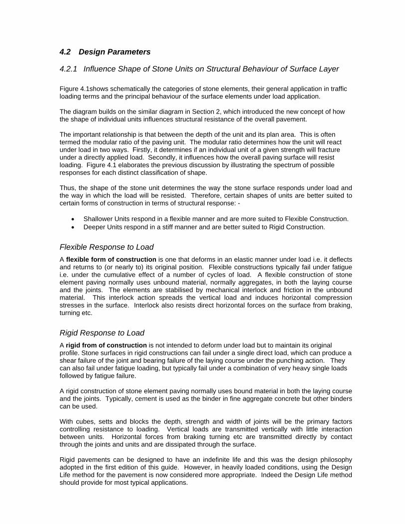
4.1.4 Full Analytical Design Method The Full Analytical Design Method is the same as that presented in the first edition of the Guide and is discussed in Section 4.8. The method involves carrying out a structural analysis using theoretical principals. A mathematical model is used to determine the relevant critical strains or stresses for different constructions. An end performance specification is produced and extensive insitu testing during construction is used to ensure compliance. The specification produced should sustain the design loading for a specified period or may be extended to a longer time span. The technique may encourage innovation and may produce cost savings. Experience and expertise is required in the application of this method.
Guidance Three primary design methods are available depending on the type of stone surface and the loading applied: - Design Life Method for pavements of deeper stone units such as Cubes andSetts. Design Life Method for pavements built with shallow stone units such as SlabsFlags and Tiles. Full Analytical Design Method, which can be applied to pavements built withany type of surfacing. The structural capacity of a stone surface is dependent on a number ofparameters, primarily the form of construction, whether flexible or rigid, theweight and frequency of traffic loads and the shape of the stone units.
4.2 Design Parameters
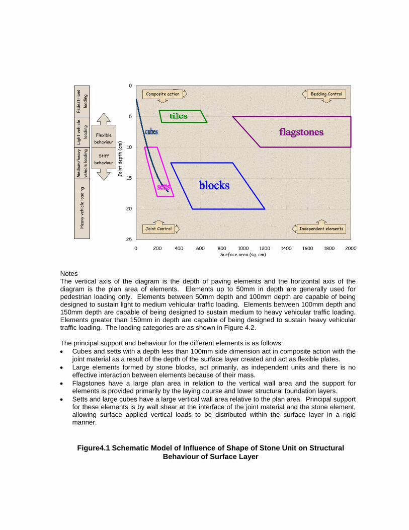
4.2.1 Influence Shape of Stone Units on Structural Behaviour of Surface Layer Figure 4.1shows schematically the categories of stone elements, their general application in traffic loading terms and the principal behaviour of the surface elements under load application. The diagram builds on the similar diagram in Section 2, which introduced the new concept of how the shape of individual units influences structural resistance of the overall pavement. The important relationship is that between the depth of the unit and its plan area. This is often termed the modular ratio of the paving unit. The modular ratio determines how the unit will react under load in two ways. Firstly, it determines if an individual unit of a given strength will fracture under a directly applied load. Secondly, it influences how the overall paving surface will resist loading. Figure 4.1 elaborates the previous discussion by illustrating the spectrum of possible responses for each distinct classification of shape. Thus, the shape of the stone unit determines the way the stone surface responds under load and the way in which the load will be resisted. Therefore, certain shapes of units are better suited to certain forms of construction in terms of structural response: -
• Shallower Units respond in a flexible manner and are more suited to Flexible Construction. • Deeper Units respond in a stiff manner and are better suited to Rigid Construction.
Flexible Response to Load A flexible form of construction is one that deforms in an elastic manner under load i.e. it deflects and returns to (or nearly to) its original position. Flexible constructions typically fail under fatigue i.e. under the cumulative effect of a number of cycles of load. A flexible construction of stone element paving normally uses unbound material, normally aggregates, in both the laying course and the joints. The elements are stabilised by mechanical interlock and friction in the unbound material. This interlock action spreads the vertical load and induces horizontal compression stresses in the surface. Interlock also resists direct horizontal forces on the surface from braking, turning etc.
Rigid Response to Load A rigid from of construction is not intended to deform under load but to maintain its original profile. Stone surfaces in rigid constructions can fail under a single direct load, which can produce a shear failure of the joint and bearing failure of the laying course under the punching action. They can also fail under fatigue loading, but typically fail under a combination of very heavy single loads followed by fatigue failure. A rigid construction of stone element paving normally uses bound material in both the laying course and the joints. Typically, cement is used as the binder in fine aggregate concrete but other binders can be used. With cubes, setts and blocks the depth, strength and width of joints will be the primary factors controlling resistance to loading. Vertical loads are transmitted vertically with little interaction between units. Horizontal forces from braking turning etc are transmitted directly by contact through the joints and units and are dissipated through the surface. Rigid pavements can be designed to have an indefinite life and this was the design philosophy adopted in the first edition of this guide. However, in heavily loaded conditions, using the Design Life method for the pavement is now considered more appropriate. Indeed the Design Life method should provide for most typical applications.

Bedding Control versus Joint Control Generally, surfaces that react flexibly rely more on the laying course (bedding) than on the joints to sustain loading, this is termed Bedding Control, while rigid surfaces rely more on the joints than the laying course, which is termed Jointing Control. However, as can be seen from Figure 4.1 stone surfaces often react in a composite manner mobilising a number of different resistance mechanisms.
Selection of Appropriate Form of Construction Thus, in general terms, shallow cubes or setts less than 100mm deep respond in a flexible manner to loads and are best suited to flexible construction. Both the joints and the laying course transmit loads to the supporting layer and have to together to support the units. Flags and slabs are solely dependent on the laying course for structural performance. As the depth of the units increases the response under load becomes stiffer. Consequently, setts and cubes greater than 150mm deep react in a rigid manner and are better suited to rigid construction. Wall shear at the joints is the primary support mechanism in rigid construction and is best achieved with bound joint materials. The laying course is of less importance structurally nevertheless; the consistency of compaction is critical in resisting punching shear. Elements can be designed using an analytical approach to operate differently from that shown in Figure 4.1 if required. For example, an appropriate bedding and support structure using a flexible joint material (such as an unbound aggregate, bituminous or flexible resin filled aggregate joint system) can support deeper setts. However, it should be noted that the design method given in BS7533 Part 10 is based on these underlying types of structural response, which are inherent in the geometry of the stone elements.
0
5
10
15
20
25
0 200 400 600 800 1000 1200 1400 1600 1800 2000Surface area (sq. cm)
Join
t de
pth
(cm
)
Hea
vy v
ehic
le lo
adin
gPe
dest
rian
s lo
adin
gLi
ght
vehi
cle
load
ing
Med
ium
/hea
vy
vehi
cle
load
ing
Bedding ControlComposite action
Joint Control Independent elements
Flexible behaviour
Stiff behaviour
Notes The vertical axis of the diagram is the depth of paving elements and the horizontal axis of the diagram is the plan area of elements. Elements up to 50mm in depth are generally used for pedestrian loading only. Elements between 50mm depth and 100mm depth are capable of being designed to sustain light to medium vehicular traffic loading. Elements between 100mm depth and 150mm depth are capable of being designed to sustain medium to heavy vehicular traffic loading. Elements greater than 150mm in depth are capable of being designed to sustain heavy vehicular traffic loading. The loading categories are as shown in Figure 4.2. The principal support and behaviour for the different elements is as follows: • Cubes and setts with a depth less than 100mm side dimension act in composite action with the
joint material as a result of the depth of the surface layer created and act as flexible plates. • Large elements formed by stone blocks, act primarily, as independent units and there is no
effective interaction between elements because of their mass. • Flagstones have a large plan area in relation to the vertical wall area and the support for
elements is provided primarily by the laying course and lower structural foundation layers. • Setts and large cubes have a large vertical wall area relative to the plan area. Principal support
for these elements is by wall shear at the interface of the joint material and the stone element, allowing surface applied vertical loads to be distributed within the surface layer in a rigid manner.
Figure4.1 Schematic Model of Influence of Shape of Stone Unit on Structural Behaviour of Surface Layer
4.2.2 Features of Stone Elements The structural capacity of a stone surface is dependent on: -
• Depth of the Stone Element that is governed by the standard sizes manufactured by producers in compliance with production standards.
• Insitu Strength of joint materials that can be ensured by specifying appropriate mixes,
good site practices and workmanship.
• Consistency of Compaction that is dependent on two factors. Firstly, the insitu moisture content, which depends on good site practices and workmanship. Secondly, the constancy of the joint width, since variations in the joint width will lead to variation in compaction of joint materials.
• Face Texture of the Stone Element that determines the bond between the joint material
and the stone.
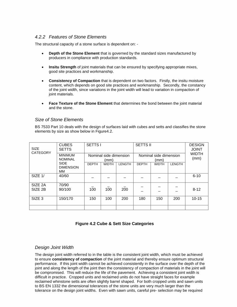
Size of Stone Elements BS 7533 Part 10 deals with the design of surfaces laid with cubes and setts and classifies the stone elements by size as show below in Figure4.2.
CUBES SETTS
SETTS I SETTS II
Nominal side dimension (mm)
Nominal side dimension (mm)
SIZE CATEGORY
MINIMUM NOMINAL SIDE DIMENSION MM
DEPTH WIDTH LENGTH DEPTH WIDTH LENGTH
DESIGN JOINT WIDTH (mm)
SIZE 1/
40/60 _ _ _ _ _ _ 6-10
SIZE 2A SIZE 2B
70/90 90/100
_ 100
_ 100
_ 200
_ _
_ _
_ _
8-12
SIZE 3
150/170 150 100 200 180 150 200 10-15
Figure 4.2 Cube & Sett Size Categories
Design Joint Width The design joint width referred to in the table is the consistent joint width, which must be achieved to ensure consistency of compaction of the joint material and thereby ensure optimum structural performance. If this joint width cannot be achieved consistently in the surface over the depth of the joint and along the length of the joint then the consistency of compaction of materials in the joint will be compromised. This will reduce the life of the pavement. Achieving a consistent joint width is difficult in practice. Cropped units and reclaimed units do not have straight faces for example reclaimed whinstone setts are often slightly barrel shaped. For both cropped units and sawn units to BS EN 1332 the dimensional tolerances of the stone units are very much larger than the tolerance on the design joint widths. Even with sawn units, careful pre- selection may be required

to achieve the design joint width. The importance of joint width is recognised by defining two ELEMENT PROFILES: -
• Design Joint Width – where the widths of all the joints in the surface are in the defined range in Figure 4.2.
• Non-Compliant Joint Width – where joints deviate from the defined range.
These Element Profiles are used in the design life method of Rigid Constructions where they influence the selection of sett size and joint material strength. However, the concept of achieving consistent joint widths also applies to flexible constructions.
Face Texture of Stone Elements The texture of vertical faces of the stone units is also an important factor for both flexible and rigid construction. Tests carried out for this guide showed that too fine a texture reduces the performance at the interface of the stone and the joint materials. This is also true of too coarse a texture in Rigid Construction where cropped units perform less well than sawn which have been reworked to reinstate a degree of texture. BS7533 Part 10 requires that sawn stone units, in either, an “unbound” Flexible Construction or in a “bound” Rigid Construction have the side faces re- textured by picking or shot blasting. In the case of flexible construction, this is required to give better frictional characteristics between the unit and fine aggregate joint materials. In the case of rigid construction, the re-texturing of the faces is required to ensure adequate adhesion between the stone and the joint materials. The degree of surface texture cannot be specified but must be ascertained by testing individual stone samples together with the intended joint material to determine if the level of adhesion is as stipulated in BS7533 Part 7.
Combined Effect of Joint Width and Face Texture on Structural Capacity of Rigid Constructions In Rigid Constructions, these two factors, compliance with the design joint width and the texture of the vertical faces of the stone unit, act in combination. Where the factors are non compliant then the effect is to require a higher strength of joint materials to achieve the intended design life or to accept a reduction in the design life. The result is to impose an upper limit of capacity beyond which the materials are not considered suitable. Tables 3,4,5,6 and 7 of BS 7533 – Part 10 apply to this issue, which is discussed in Section 4.7 of this Guide dealing with Rigid Construction Pavements.
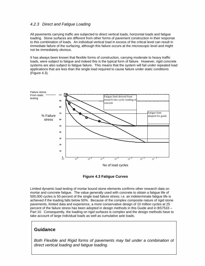
4.2.3 Direct and Fatigue Loading All pavements carrying traffic are subjected to direct vertical loads, horizontal loads and fatigue loading. Stone surfaces are different from other forms of pavement construction in their response to this combination of loads. An individual vertical load in excess of the critical level can result in immediate failure of the surfacing, although this failure occurs at the microscopic level and might not be immediately obvious. It has always been known that flexible forms of construction, carrying moderate to heavy traffic loads, were subject to fatigue and indeed this is the typical form of failure. However, rigid concrete systems are also subject to fatigue failure. This means that the system will fail under repeated load applications that are less than the single load required to cause failure under static conditions (Figure 4.3). Failure stress
0
10
20
30
40
50
60
70
80
90
100
Fatigue limit derived from research into cyclic loading of concrete
Fatigue limit adopted for guide
100 101 102 103 104 105 106 107
From static testing % Failure stress
No of load cycles
Figure 4.3 Fatigue Curves Limited dynamic load testing of mortar bound stone elements confirms other research data on mortar and concrete fatigue. The value generally used with concrete to obtain a fatigue life of 500,000 cycles is 50 percent of the single load failure stress; i.e. an indeterminate fatigue life is achieved if the loading falls below 50%. Because of the complex composite nature of rigid stone pavements, limited data and experience, a more conservative design of 10 million cycles at 25 percent of the failure stress has been adopted in design methods in this Guide and in BS7533 – Part 10. Consequently, the loading on rigid surfaces is complex and the design methods have to take account of large individual loads as well as cumulative axle loads.
Guidance Both Flexible and Rigid forms of pavements may fail under a combination ofdirect vertical loading and fatigue loading.
4.2.4 Flexible Construction Built with Deeper Stone Units The structural design of this type of construction should comply with BS 7533 Part 10.
Sub-Forms of Flexible Construction In pavements constructed using any shape of stone elements there are two sub-forms of flexible pavements depending on the composition of the support structure:
• A flexible surface layer laid upon a flexible unbound base. • A flexible surface layer laid upon a flexible bound base.
Flexible Bases A flexible base can be either: -
• Unbound e.g. type 1 sub base or similar laid in a flexible manner.
• Bound e.g. bitumen macadam where the material specification is such that the layer acts in a flexible manner.
In no circumstances should rigid materials be introduced in this form of construction i.e. cement bound aggregates should not used as sub bases or road bases; neither should stiff heavy-duty asphaltic or bitumen macadam.
Flexible Surface Layer – Deep Stone Units BS 7533 Part 7 differentiates two types of flexible surface layer, by the width of the joint between the units: -
• Stone Units with Narrow Joints (2-4 mm) - In these surfaces sawn units manufactured to strict dimensional tolerances are used, which allow tight joints of 2-4mm. This is akin to laying concrete or clay pavers, which is dealt with in associated part of BS 7533 and is not discussed in any detail in this Guide.
• Stone Units with Wide Joints (8-12 mm) – Traditional Dry Bound Surfaces - These are
sometimes referred to as “dry bound” stone surfacing and are the traditional form of construction throughout Europe. Cropped or sawn units are used. Cropped Units have irregular sides. Sawn units although produced to the EN standards, require the wider joint width because of the less strict dimensional tolerance. Therefore, the joint widths need to be wider to accommodate the variations in size of the units and are typically 8-12 mm. BS 7533 requires that the faces of sawn units are re-textured to ensure the frictional bond is developed.
Structural Capacity of Flexible Surface Built With Deep Stone Units with Wide Joints (8-12 mm) Flexible Constructions, using this latter type of surface can be found operating under all loading categories throughout Europe. However, after the review of their average performance, reinforced by testing undertaken for this Guide, the conclusion is that if designed using the Design Life Method then these forms of constructions are only capable of carrying lighter loadings. If the limitation on the applied load is exceeded, inelastic and permanent deformation will occur in the various pavement layers when the applied stress exceeds the shear strength of the aggregate matrix. Rutting will occur as the result of an accumulation of permanent deformations throughout the depth of the structure. Permanent deformation will occur until equilibrium is reached. However, a further increase in applied stress, through an increase in the dynamic load, will result in additional
permanent movement until a new equilibrium point is again reached. The effect of this is seen where roads formed by a flexible construction are stable for many years (> 100) until heavier vehicles use the carriageway when a further deformation occurs which renders the carriageway un-serviceable. As a result, flexible construction is not recommended for use under heavy loading or severe stress sites. The predominant mode of failure of Flexible Surfaces is that of fatigue under repeated cyclical loading. This is similar to other forms of road and pavement constructions e.g. asphalt, bitumen macadam, block pavers. Thus, the Design Life philosophy is readily applied to this form of construction of stone surfaces. It is recognised that there are examples both here and on the Continent of this type of surface surviving under heavier loading but as yet there is no conclusive evidence to determine why this is the case. Obviously every case should be treated individually and when the project demands adopting flexible surfacing under heavy loading, it is recommended that the full analytical process is used together with a full risk analysis, backed up with extensive trials, before the specification for the pavement is finally determined.
Advantages and Disadvantages of Flexible Construction The most significant benefit in using unbound aggregate to achieve surface layer stability and composite action is sustainability. Any loss of surface profile can be rectified simply and all the surface components can be reused. Other benefits associated with constructing a flexible stone surface are discussed in Section 2.
Guidance Flexible pavements built with deeper stone units such as cubes, setts or blocks will carry moderate loads but will deform under heavy loads. Flexible pavements are not recommended for use in severe stress sitesunless a full analytical design is undertaken.

4.2.5 Flexible Construction Built with Shallow Stone Units - (Slabs, Flagstones and Tiles) for Lightly Trafficked Pavements
The structural design for this type of flexible construction should comply with BS7533 Part 8 - Guide for the Structural Design of Lightly Trafficked Pavements of Precast Concrete Flags and Stone Slabs. It is recognised that in BS 7533 Part 4 the use of fine concrete in either of the laying course and the joints is allowable this is to reflect traditional practices throughout the country. However research for this guide indicates that structural response is influenced by the shape of the units. Thus it is recommend that the structural design should follow the principle of flexible construction with sand laying course and joints and only this form of construction has been considered in structural design terms. Therefore, in this guide only flexible forms are recommended for slabs and flags. Alternatively it is recommended that a full analytical design is undertaken and that the constructions are extensively tested.
Sub-Forms of Flexible Construction In pavements constructed using any shape of stone elements there are two sub-forms of flexible pavements depending on the composition of the support structure: -
• A flexible surface layer laid upon a flexible unbound base. • A flexible surface layer laid upon a flexible bound base.
Flexible Bases A flexible base can be either: -
• Unbound e.g. type 1 sub base or similar laid in a flexible manner. • Bound e.g. bitumen macadam where the material specification is such that the layer acts
in a flexible manner. In no circumstances should rigid materials be introduced in this form of construction i.e. cement bound aggregates should not used as sub bases or road bases; neither should stiff heavy-duty asphaltic or bitumen macadam.
Flexible Surface Layer – Shallow Stone Units BS 7533 Part 8 stipulates only one type of flexible surface layer: -
• Stone Units with Narrow Joints (2-4 mm) - In these surfaces sawn stone units manufactured to strict dimensional tolerances are used, which allow tight joints of 2-4mm.
Structural Capacity of Flexible Surface Built with Shallow Stone Units – Slabs, Flagstones and Tiles These types of surface are not considered suitable for all but the most lightly trafficked areas. Even then, they should be used with caution as these areas are often subjected to heavier than designed for traffic loads for example one-off events or maintenance operations.

Advantages and Disadvantages of Flexible Construction- Slabs, Flagstones and Tiles The most significant benefit of construction of shallow stone units is cost. They provide a cost effective surface in pedestrian areas in comparison to deeper stone units. They also have visually attractive qualities. The primary disadvantage is their structural weakness and their vulnerability to over running by vehicles, which impose loads well above the capacity of the stone units. This can lead to instantaneous fracturing of the unit.
Guidance Flexible pavements built with shallow stone units (slabs, flags and tiles) areonly recommended for very lightly loaded areas and are very prone tofracturing if over run by heavier vehicles.
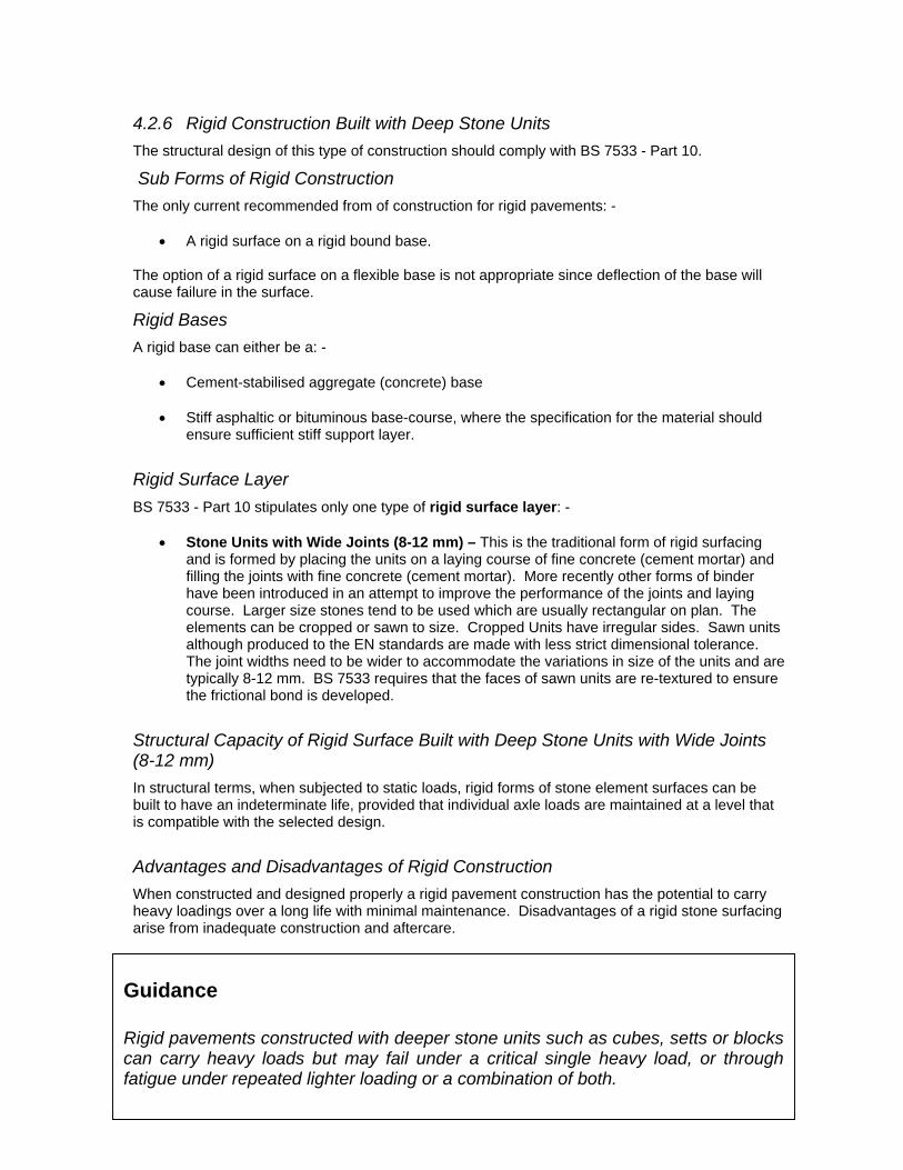
4.2.6 Rigid Construction Built with Deep Stone Units The structural design of this type of construction should comply with BS 7533 - Part 10.
Sub Forms of Rigid Construction The only current recommended from of construction for rigid pavements: -
• A rigid surface on a rigid bound base. The option of a rigid surface on a flexible base is not appropriate since deflection of the base will cause failure in the surface.
Rigid Bases A rigid base can either be a: -
• Cement-stabilised aggregate (concrete) base
• Stiff asphaltic or bituminous base-course, where the specification for the material should ensure sufficient stiff support layer.
Rigid Surface Layer BS 7533 - Part 10 stipulates only one type of rigid surface layer: -
• Stone Units with Wide Joints (8-12 mm) – This is the traditional form of rigid surfacing and is formed by placing the units on a laying course of fine concrete (cement mortar) and filling the joints with fine concrete (cement mortar). More recently other forms of binder have been introduced in an attempt to improve the performance of the joints and laying course. Larger size stones tend to be used which are usually rectangular on plan. The elements can be cropped or sawn to size. Cropped Units have irregular sides. Sawn units although produced to the EN standards are made with less strict dimensional tolerance. The joint widths need to be wider to accommodate the variations in size of the units and are typically 8-12 mm. BS 7533 requires that the faces of sawn units are re-textured to ensure the frictional bond is developed.
Structural Capacity of Rigid Surface Built with Deep Stone Units with Wide Joints (8-12 mm) In structural terms, when subjected to static loads, rigid forms of stone element surfaces can be built to have an indeterminate life, provided that individual axle loads are maintained at a level that is compatible with the selected design.
Advantages and Disadvantages of Rigid Construction When constructed and designed properly a rigid pavement construction has the potential to carry heavy loadings over a long life with minimal maintenance. Disadvantages of a rigid stone surfacing arise from inadequate construction and aftercare.
Guidance Rigid pavements constructed with deeper stone units such as cubes, setts or blockscan carry heavy loads but may fail under a critical single heavy load, or throughfatigue under repeated lighter loading or a combination of both.

4.3 Traffic Loading
4.3.1 Basic Loading for pavements built with deeper stone units BS 7533 - Part 10, stipulates the traffic loading on natural stone pavements built with deeper stone units. There are a number of categories, based on the number of heavy vehicles per day as shown in Figure 4.4.
Site Heavy Typical applications
Category Vehicles per
Day IA <100 Adopted highways and commercial developments used IB <30 regularly by heavy vehicles IIA <10 Adopted Highways and other roads e.g. Cul-de-sac. Petrol station forecourts. Pedestrian projects subject to regular heavy traffic IIB <5 Car Parks receiving occasional heavy traffic Footways
regularly overridden by vehicular traffic IIIA <1 Pedestrian projects receiving only occasional heavy traffic Footways overridden by occasional vehicular traffic IIIB NIL Car parks receiving no heavy traffic Footways likely to be overridden by no more than occasional
vehicular traffic. IV NIL Private drives, paths, patio, hard landscaping Areas receiving pedestrian traffic only e.g. school playgrounds.
Figure 4.4 Categories of traffic loading for natural stone pavements –deeper stone units
The designer must consider these categories very carefully and adopt a conservative approach to assessing the typical application. For instance, it is very rare that car parks will receive no heavy traffic at some time in their life, heavy vehicles may pass over the surface during maintenance operations and as discussed one pass of such heavy loads could be critical for certain forms of construction.
4.3.2 Effect of Site Characteristics on Loading Research for this guide has also found that stone surfaces are strongly affected by secondary loadings, which are induced by the layout and geometry of a particular site. Site conditions such as gradients, junctions, restricted road width, channelisation, traffic calming ramps, drainage channels or where there are sharp variations in the surface level, have the effect of concentrating the loading. BS 7533 - Part 10 recognises the additional effect of these site conditions is to impose extra, often high value, horizontal loading on the surface. The horizontal stresses are both compressive and tensile. Normal cement bound systems have little tensile strength and the imposition of these high tensile loads can cause failure in the horizontal plane. The structural design of the overall

pavement in terms of vertical loading remains unchanged but, because of the higher horizontal tensile stresses, design should be reconsidered. BS 7533 - Part 10 requires that in localised areas of high horizontal loading, the traffic figures should be multiplied by a factor of 2 before carrying out the design of the surface. This is a new concept, which is particular to stone surfaces. Research for this guide suggests that the impact of site geometry is in fact greater than previously assumed and that the factor of 2 given in the BS Part 10 might be insufficient. The designer may wish to consider factors given in table 4.5, which defines categories of site conditions where the secondary loadings might be more severe.
Site Category Weighting Factor Description
A 1.0 Standard carriageway dimensions, or wide-open area. Level site and traffic movement linear.
B 2.0 As above with radius of curvature < 100m and/or gradient > 10%. Vehicles turning.
C 3.0 Sub-standard carriageway width.
D 4.0 As above with radius of curvature < 100m and/or gradient > 10%.
Notes (1) The gradient and tightness of bends will affect the stresses imposed by the vehicles on the surfacing. (2) Lane widths less than the conventional 3.65 metres will produce a degree of channelisation. As the traffic lane width approaches 3.0m and less, full channelisation occurs, i.e. vehicle width restricts any lateral movement and loading becomes concentrated over the same area. (3) Braking and acceleration is assumed to apply to all site categories. (4) Site category D should be used for all other site conditions not described above. However, if the designer has good evidence that a design has performed satisfactorily over a reasonable time period in a similar context, he is free to specify it.
Figure 4.5 Characteristics of Sites for Stone Pavements
The weighting factor given for any site category in figure 4.5 has to be applied to the basic number of heavy vehicles per day that the site is expected to carry from Figure 4.4 to arrive at an adjusted value for traffic loading.
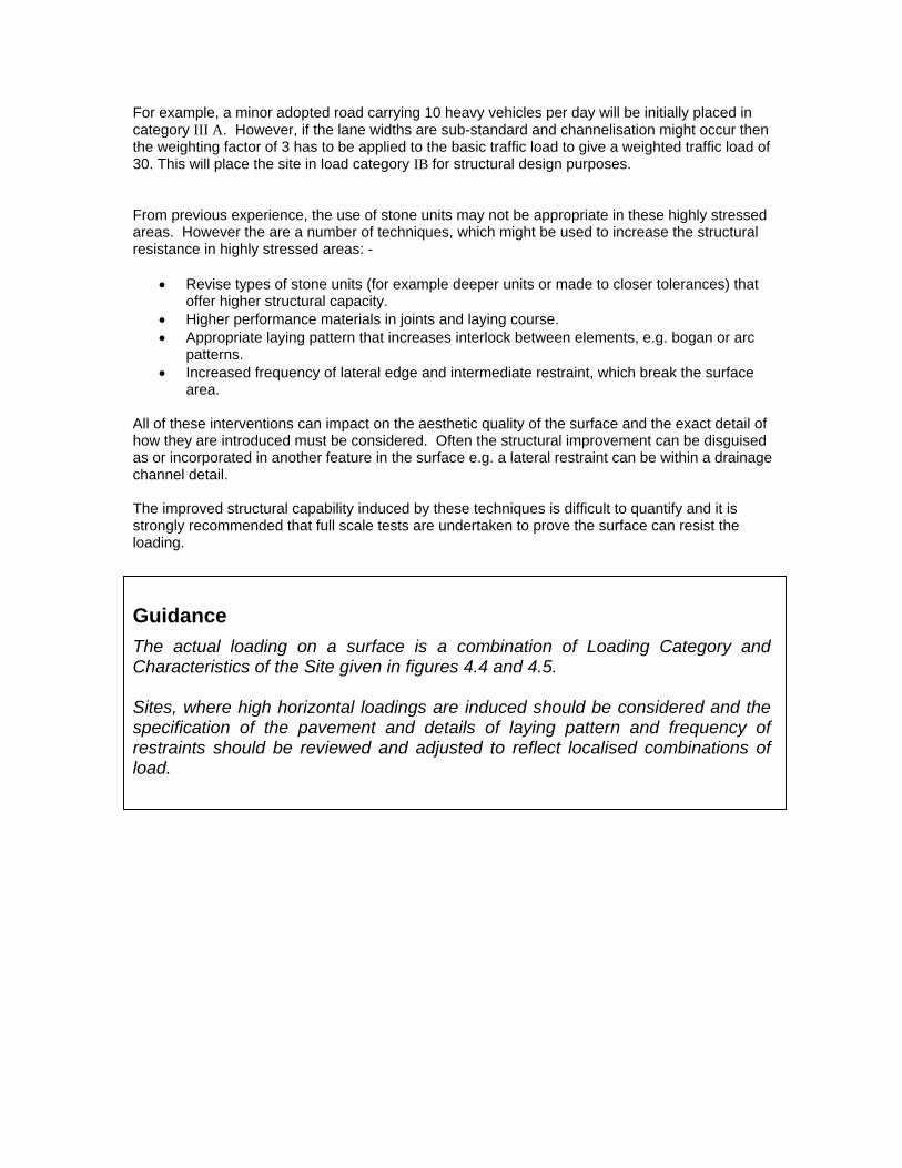
For example, a minor adopted road carrying 10 heavy vehicles per day will be initially placed in category III A. However, if the lane widths are sub-standard and channelisation might occur then the weighting factor of 3 has to be applied to the basic traffic load to give a weighted traffic load of 30. This will place the site in load category IB for structural design purposes. From previous experience, the use of stone units may not be appropriate in these highly stressed areas. However the are a number of techniques, which might be used to increase the structural resistance in highly stressed areas: -
• Revise types of stone units (for example deeper units or made to closer tolerances) that offer higher structural capacity.
• Higher performance materials in joints and laying course. • Appropriate laying pattern that increases interlock between elements, e.g. bogan or arc
patterns. • Increased frequency of lateral edge and intermediate restraint, which break the surface
area. All of these interventions can impact on the aesthetic quality of the surface and the exact detail of how they are introduced must be considered. Often the structural improvement can be disguised as or incorporated in another feature in the surface e.g. a lateral restraint can be within a drainage channel detail. The improved structural capability induced by these techniques is difficult to quantify and it is strongly recommended that full scale tests are undertaken to prove the surface can resist the loading.
Guidance The actual loading on a surface is a combination of Loading Category and Characteristics of the Site given in figures 4.4 and 4.5. Sites, where high horizontal loadings are induced should be considered and the specification of the pavement and details of laying pattern and frequency of restraints should be reviewed and adjusted to reflect localised combinations of load.

4.4 Design Life Method for Deeper Stone units
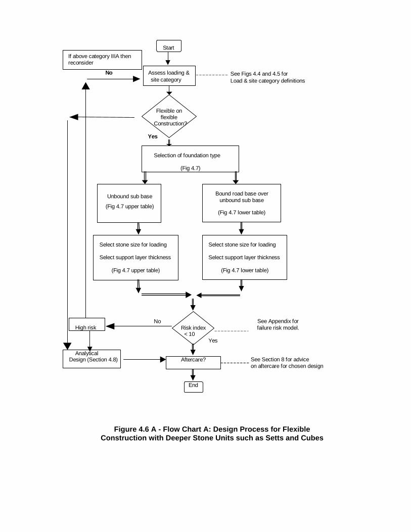
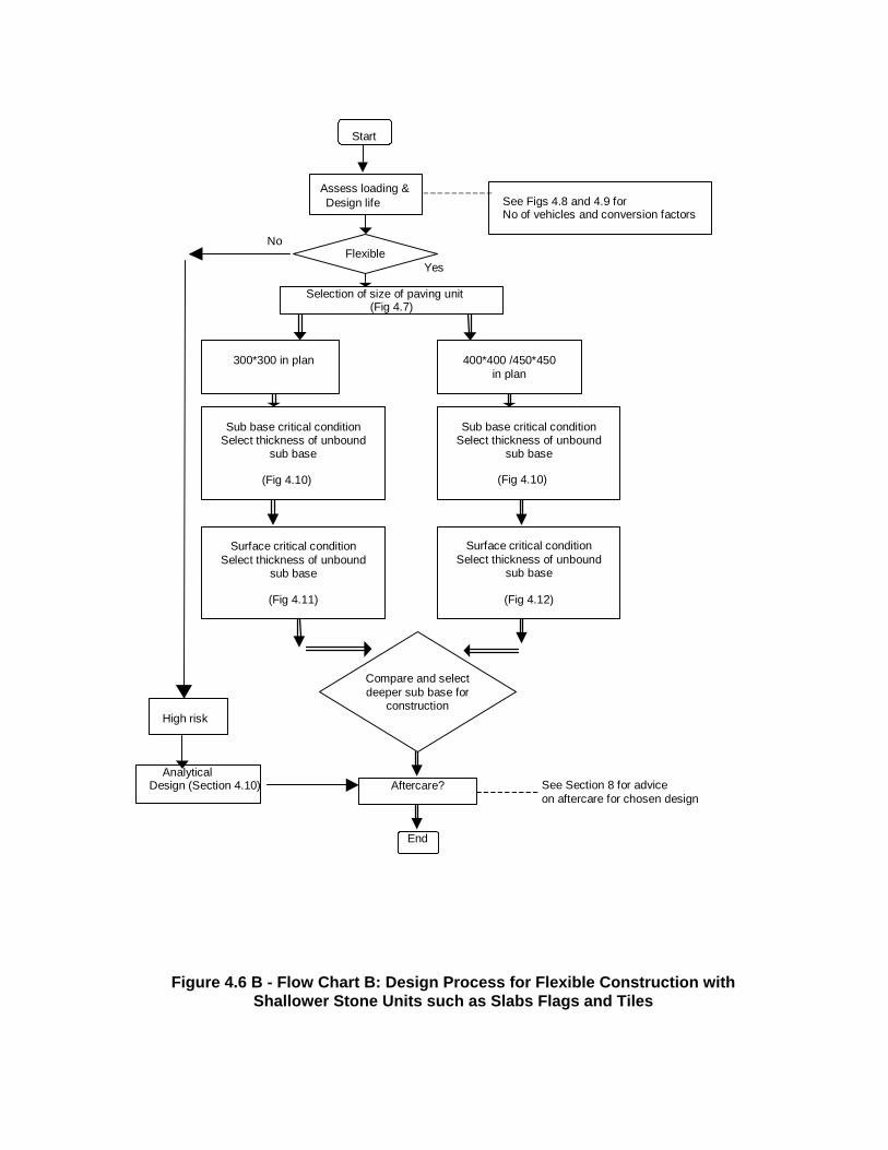
4.4.1 Flow Charts The process for the structural design using the design life method for a pavement built with deeper stone units is shown on the following flow charts, which apply to both basic forms of construction, flexible and rigid. They do no apply to stone surfaces built with shallow stone units, which are dealt with later in this guide. Flow Chart A is for flexible construction in deeper stone units such as cubes and setts Flow Chart B is flexible construction in shallower stone units such as slabs flags and tiles Flow Chart C is for rigid construction in deeper stone units such as cubes and setts
See Section 8 for advice on aftercare for chosen design
Assess loading &site category
Selection of foundation type
(Fig 4.7)
Unbound sub base
(Fig 4.7 upper table)
Select stone size for loading
(Fig 4.7 upper table)
Aftercare?
See Figs 4.4 and 4.5 forLoad & site category definitions
Start
End
Risk index< 10
See Appendix for failure risk model.
Yes
No High risk
Flexible on flexible
Construction?
Select support layer thickness
Analytical Design (Section 4.8)
Yes
No
If above category IIIA then reconsider
Bound road base over unbound sub base
(Fig 4.7 lower table)
Select stone size for loading
(Fig 4.7 lower table)
Select support layer thickness
Figure 4.6 A - Flow Chart A: Design Process for Flexible Construction with Deeper Stone Units such as Setts and Cubes
See Section 8 for advice on aftercare for chosen design
Assess loading &Design life
Selection of size of paving unit (Fig 4.7)
Sub base critical condition Select thickness of unbound
sub base
(Fig 4.10)
Surface critical condition Select thickness of unbound
sub base
(Fig 4.11)
Aftercare?
See Figs 4.8 and 4.9 for No of vehicles and conversion factors
Start
End
Yes
No
High risk
Analytical Design (Section 4.10)
Sub base critical condition Select thickness of unbound
sub base
(Fig 4.12)
300*300 in plan 400*400 /450*450 in plan
(Fig 4.10)
Surface critical condition Select thickness of unbound
sub base
Compare and select deeper sub base for
construction
Flexible
Figure 4.6 B - Flow Chart B: Design Process for Flexible Construction with Shallower Stone Units such as Slabs Flags and Tiles

See Section 8 for advice on aftercare for chosen design
Assess loading &Design life
Selection of sub base and road base course thickness(Fig 4.13)
Select sett size for loading category and design life
(Fig 4.14)
For element profiles of design joint width and face texture check suitability of sett size and select strength of joint
materials
(Fig 4.17)
Aftercare?
See Figs 4.4and 4.5 forLoading and site category definitions
Start
End
Yes
No
High risk
Analytical Design (Section 4.8)
Select sett size for loading category and design life
(Fig 4.17)
Full Depth Joint Construction
Joint Topping Construction
(Fig 4.15)
For element profiles of design joint width and face texture check suitability of sett size and select strength of joint
materials
Rigid on rigid
See Appendix for failure risk model.
Risk index
< 10
Figure 4.6 C -Flow Chart C: Design Process for Rigid Construction with Deeper Stone Units such as Setts and Cubes

4.5 Design Life Method -Flexible Construction – Deeper stone units- Cubes and Setts
4.5.1 BS 7533 Part 10 BS7533 Part 10 has two design tables for flexible surface construction: -
• Table 9 for Flexible surfaces on an “unbound” flexible base
• Table 10 for Flexible surfaces on a “bound” flexible base. The tables relate to the loading categories described above and give combinations of: -
• Overall pavement thickness. • The combined thickness of the sub-base and unbound roadbase relative to the California
Bearing Ratio (CBR) of the sub grade. • The thickness of the laying course. • The sett size category.
As discussed earlier the basic loading categories I to IV given in Table 4.4 must be adjusted to take account of the other factors listed in Table 4.5 in order to select a suitable type of surface for the design traffic loading. The tables from BS 7533 Part 10 are shown in Figure 4.7. Using these tables in combination the designer can select the layers to arrive at the overall construction of the Flexible pavement: -
• Foundation, which is dependent on the CBR value of the sub-grade below the pavement • Roadbase and/ or Basecourse, which is also dependent on the strength of the sub-grade • The Laying Course thickness, which is 40mm for all selections • The size and type of Cubes or Setts for the surface
It should be noted that BS 7533 – Part 10 tables refer only to Roadbase but this is a generic term used to cover both roadbase and basecourse. Either can be used in practice subject to the requirements of general road design standards. For lightly trafficked areas, a basecourse may be sufficient; for more heavily loaded areas, both a basecourse and a roadbase might be specified. For example the 160mm thickness specified under category II load in the lower table might comprise a 100mm roadbase with a 60mm basecourse (see Section 6) It will be apparent that Flexible Surfaces on flexible unbound road bases or sub bases are only recommended for the two lightest loading categories and are not considered suitable for heavily loaded conditions unless a full analytical approach is taken. Flexible surfaces on bound roadbases over unbound sub bases have a higher structural capacity when deeper setts are selected and can be used in Category II sites. If size 2 Setts are to be used under this loading then they must have sawn and re-textured sides. If size 3 Setts are selected then they may be cropped.
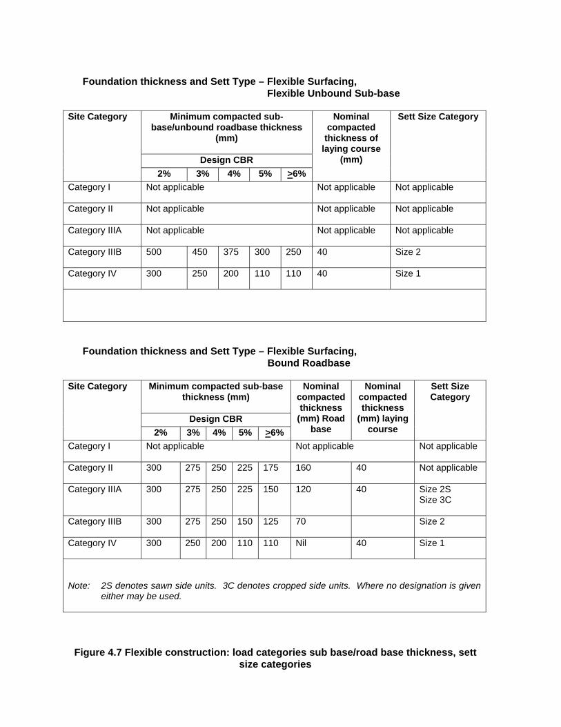
Foundation thickness and Sett Type – Flexible Surfacing,
Flexible Unbound Sub-base
Minimum compacted sub-base/unbound roadbase thickness
(mm)
Design CBR
Site Category
2% 3% 4% 5% >6%
Nominal compacted
thickness of laying course
(mm)
Sett Size Category
Category I Not applicable Not applicable Not applicable
Category II Not applicable Not applicable Not applicable
Category IIIA Not applicable Not applicable Not applicable
Category IIIB 500 450 375 300 250 40 Size 2
Category IV 300 250 200 110 110 40 Size 1
Foundation thickness and Sett Type – Flexible Surfacing,
Bound Roadbase
Minimum compacted sub-base thickness (mm)
Design CBR
Site Category
2% 3% 4% 5% >6%
Nominal compacted thickness
(mm) Road base
Nominal compacted thickness
(mm) laying course
Sett Size Category
Category I Not applicable Not applicable Not applicable
Category II 300 275 250 225 175 160 40 Not applicable
Category IIIA 300 275 250 225 150 120 40 Size 2S Size 3C
Category IIIB 300 275 250 150 125 70 Size 2
Category IV 300 250 200 110 110 Nil 40 Size 1
Note: 2S denotes sawn side units. 3C denotes cropped side units. Where no designation is given
either may be used.
Figure 4.7 Flexible construction: load categories sub base/road base thickness, sett size categories
4.5.2 Laying Patterns and Joints in Flexible Construction BS 7533 Part 10 does not give any recommendations on laying patterns. However, Part 7 does recognise that laying patterns and joint dimension are critical to the performance of a flexible surface. Laying patterns will be influenced by the desired appearance of the surface but as the laying patterns can contribute much to the stability of the pavement under traffic loading, it is essential that both visual and structural criteria be considered. Common laying patterns for setts and cubes are given in Section 8 of this Guide. Section 7 of this Guide discusses in more detail how to achieve laying patterns but in terms of their structural importance the following points are crucial.
4.5.3 Cubes in Flexible Construction Cubes used in vehicular trafficked areas within a flexible construction should be laid in curved patterns described as bogan or arc pattern, the arc being in the direction of the traffic flow, or uphill. Cubes laid in an un-bonded pattern, rows and columns, will provide little flexural strength and should only be used on hard standing areas, such as vehicle parking areas.
4.5.4 High Stress Areas As discussed in Section 4.3 and Figure 4.5 certain site conditions in localised areas high tensile stresses can be produced. In these areas, more stable elements should be used. For example in flexible construction where cubes or setts are chosen then consideration might be given to increasing the depth of the element to a minimum of 150mm. Alternatively consideration might be given to using a rigid construction in high stress areas.
Guidance Flexible forms of construction should comply with BS7533 Part 10 and thecombination of foundation, road base and laying course and sett size typeshould be selected from the appropriate design tables. Flexible Surfaces on flexible unbound road bases or sub bases are onlyrecommended for the two lightest loading categories and are not considered suitable for heavily loaded conditions unless a full analyticalapproach is taken. Appropriate laying patterns should be used.

4.6 Design Life Method - Lightly Trafficked Pavements -Flags and Slabs
4.6.1 BS7533 Part 8 The structural design of lightly trafficked pavements where the use of flagstone and tiles might be appropriate is dealt with in BS7533 Part 8 Guide For The Structural Design Of Lightly Trafficked Pavements Of Precast Concrete Flags And Stone Slabs. It is recognised that in BS 7533 Part 4 the use of fine concrete in either of the laying course and the joints is allowable, this is to reflect traditional practices throughout the country. However research for this guide indicates that structural response is influenced by the shape of the units. Thus it is recommend that the structural design should follow the principle of flexible construction with sand laying course and joints and only this form of construction has been considered in structural design terms. Therefore, in this guide only flexible forms are recommended for slabs and flags. Alternatively it is recommended that a full analytical design is undertaken and that the constructions are extensively tested. The design method ascertains the depth of construction necessary to prevent either the flag/slab surface or the sub grade from becoming overstressed. Firstly the light traffic loading is evaluated as the number of equivalent standard axles over the design life of the pavement and is obtained by factoring the number of vehicles as of a given type and then multiplying by the factored number by the number of years the pavement it is to last. Figures 4.8 and 4.9 give the appropriate factors.
Figure 4.8 Number of commercial vehicles
Location Number of commercial vehicles Per day
Residential Areas 1 Small Shopping Areas 5 Large shopping Areas 10 Precincts and Pedestrianised Areas 15
The number of vehicles has then to be converted into a number of standard axles using the following multipliers Figure 4.9 Standard Axle Conversion
Vehicle Type Number of Standard Axles per commercial vehicle
2 axle Rigid 0.34 3 axle Rigid 1.70 4 axle 2.60
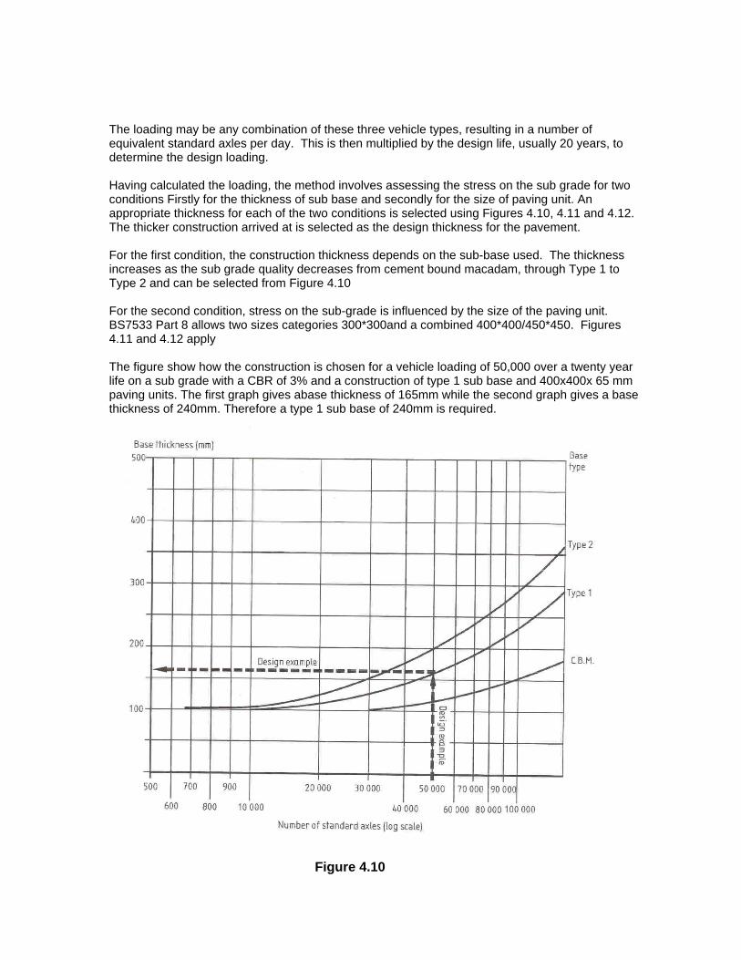
The loading may be any combination of these three vehicle types, resulting in a number of equivalent standard axles per day. This is then multiplied by the design life, usually 20 years, to determine the design loading. Having calculated the loading, the method involves assessing the stress on the sub grade for two conditions Firstly for the thickness of sub base and secondly for the size of paving unit. An appropriate thickness for each of the two conditions is selected using Figures 4.10, 4.11 and 4.12. The thicker construction arrived at is selected as the design thickness for the pavement. For the first condition, the construction thickness depends on the sub-base used. The thickness increases as the sub grade quality decreases from cement bound macadam, through Type 1 to Type 2 and can be selected from Figure 4.10 For the second condition, stress on the sub-grade is influenced by the size of the paving unit. BS7533 Part 8 allows two sizes categories 300*300and a combined 400*400/450*450. Figures 4.11 and 4.12 apply The figure show how the construction is chosen for a vehicle loading of 50,000 over a twenty year life on a sub grade with a CBR of 3% and a construction of type 1 sub base and 400x400x 65 mm paving units. The first graph gives abase thickness of 165mm while the second graph gives a base thickness of 240mm. Therefore a type 1 sub base of 240mm is required.
Figure 4.10
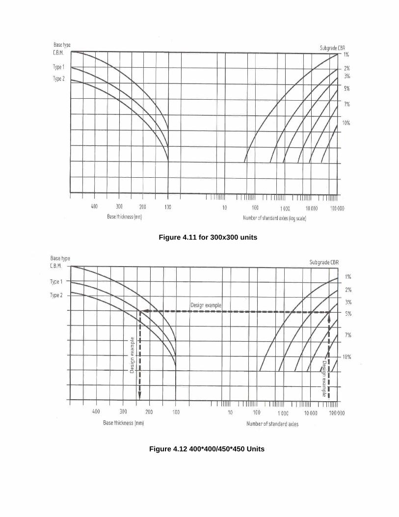
Figure 4.11 for 300x300 units
Figure 4.12 400*400/450*450 Units

There are several important assumptions to note in the above method. The first is the assumption that the construction is flexible even with the allowance of cement bound sub base material as one of the sub base types. It is assumed that the response of a CBM is flexible enough not to cause compatibility problems. However, care must be taken in the specification and construction that this layer does not become too stiff. Thus following the design rule that a rigid surface should not be laid on a flexible bed, the use of a rigid laying course and of rigid joints is implicitly precluded. It is recognised that using rigid type (cement or modified cement) materials in the beds and joints of these surfaces is a traditional form of construction, which makes the surface less vulnerable to wash out and nowadays less prone to the suction of vacuum machines used in cleaning. But, the designer must be aware that specifying rigid bed and joint materials in such flexible surfaces, is no longer recommended in structural design terms. If sealing the surface to avoid loss of joint materials is an issue, other more contemporary materials should be considered as solutions. These proprietary materials offer a degree of flexibility in sealing the surface. BS7533 Part 8 also notes that paving flags/slabs are often laid as overlays to asphaltic or bituminous surfaces. Annex B gives a method for assessing the equivalent thickness of the existing blacktop layers in terms of type 1 sub base which allows the structural capacity to be determined as above. Again the assumption here is that the surface will be laid in a flexible manner. Empirical evidence suggests that new flexible construction consisting of slabs /flags laid on a blacktop basecourse or roadbase, can carry heavier traffic loads and survive for a substantial design life. This is particularly true when the beds and joints are formed in a selected modified bitumen material. Further research and trials are, however, required to substantiate this theory.
4.6.2 Selection of laying course and joint materials for Slabs Flags and Tiles It is clear that in order to maintain the integrity of flagged and slabbed pavements the laying course and jointing materials need to be restricted to unbound aggregates. The laying course is the main support mechanism and it is vital to achieve consistency of compaction in this layer. This requires that a consistent depth be achieved within the tolerances stated and the material to be laid and compacted at its optimum moisture content. Therefore, the moisture content of the material when laid should not deviate markedly from the optimum. The specification of this material is discussed in Sections 6 & 7.
Guidance Although BS 7533 Part 4 details both forms of construction in terms ofinstallation BS 7533 Part 8 implicitly recommends flexible forms when the pavement is carrying vehicular traffic. The traffic loading for slab and flag pavements is assessed differently fromsurfaces with deeper units and is relative lighter. Surfaces built with shallow units are very susceptible to single critical loading and measures should be considered to prevent overrun by very heavyvehicles. Appropriate laying patterns should be used.
4.7 Design Life Method - Rigid Construction - Cubes and Setts
4.7.1 BS 7533 Part 10 BS 7533 Part 10 has several design tables for rigid construction i.e. rigid surfacing on rigid base, these relate to:
• The sett type and size as given in Figure 4.2
• The design life selected from the range 10 years, 20 years or 40 years
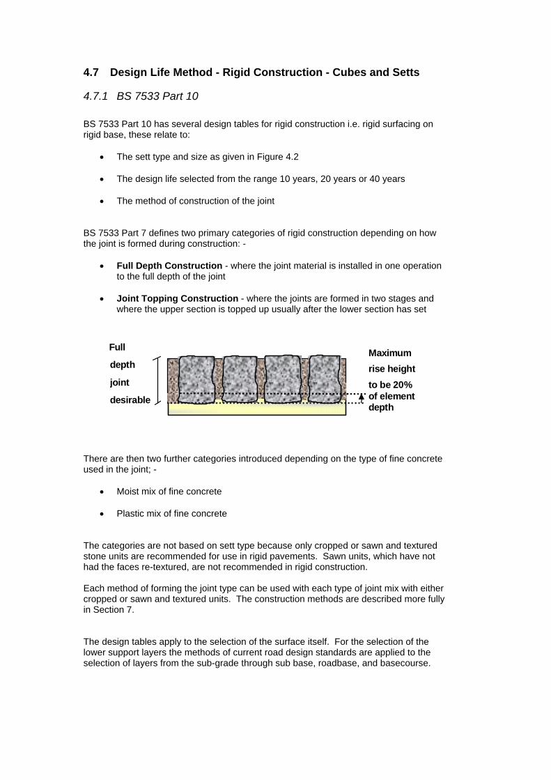
• The method of construction of the joint BS 7533 Part 7 defines two primary categories of rigid construction depending on how the joint is formed during construction: -
• Full Depth Construction - where the joint material is installed in one operation to the full depth of the joint
• Joint Topping Construction - where the joints are formed in two stages and
where the upper section is topped up usually after the lower section has set
Maximumrise heightto be 20%of elementdepth
Full
depth
joint
desirable
There are then two further categories introduced depending on the type of fine concrete used in the joint; -
• Moist mix of fine concrete
• Plastic mix of fine concrete The categories are not based on sett type because only cropped or sawn and textured stone units are recommended for use in rigid pavements. Sawn units, which have not had the faces re-textured, are not recommended in rigid construction. Each method of forming the joint type can be used with each type of joint mix with either cropped or sawn and textured units. The construction methods are described more fully in Section 7. The design tables apply to the selection of the surface itself. For the selection of the lower support layers the methods of current road design standards are applied to the selection of layers from the sub-grade through sub base, roadbase, and basecourse.
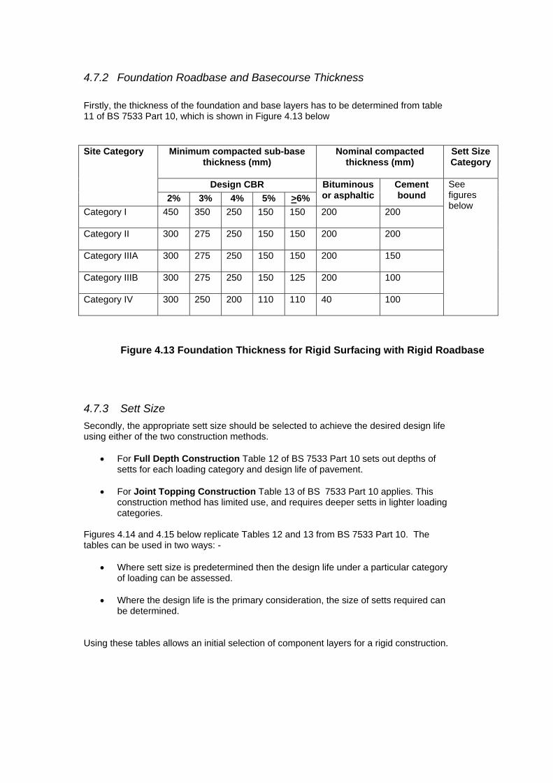
4.7.2 Foundation Roadbase and Basecourse Thickness Firstly, the thickness of the foundation and base layers has to be determined from table 11 of BS 7533 Part 10, which is shown in Figure 4.13 below
Minimum compacted sub-base thickness (mm)
Nominal compacted thickness (mm)
Sett Size Category
Design CBR
Site Category
2% 3% 4% 5% >6% Bituminous or asphaltic
Cement bound
Category I 450 350 250 150 150 200 200
Category II 300 275 250 150 150 200 200
Category IIIA 300 275 250 150 150 200 150
Category IIIB 300 275 250 150 125 200 100
Category IV 300 250 200 110 110 40 100
See figures below
Figure 4.13 Foundation Thickness for Rigid Surfacing with Rigid Roadbase
4.7.3 Sett Size Secondly, the appropriate sett size should be selected to achieve the desired design life using either of the two construction methods.
• For Full Depth Construction Table 12 of BS 7533 Part 10 sets out depths of setts for each loading category and design life of pavement.
• For Joint Topping Construction Table 13 of BS 7533 Part 10 applies. This
construction method has limited use, and requires deeper setts in lighter loading categories.
Figures 4.14 and 4.15 below replicate Tables 12 and 13 from BS 7533 Part 10. The tables can be used in two ways: -
• Where sett size is predetermined then the design life under a particular category of loading can be assessed.
• Where the design life is the primary consideration, the size of setts required can
be determined. Using these tables allows an initial selection of component layers for a rigid construction.

Design Life
10 Years 20 Years 40 Years
Site Category
Sett Size Relevant Table
Sett Size Relevant Table
Sett Size Relevant Table
Category IA
3 5 or 6 3 5 or 6 3 5 or 6
Category IB 2B 4 2B 4 3 5 or 6 Category IIA 2A 4 2B 4 3 5 or 6 Category IIIA 2A 3 2B 4 3 5 or 6 Category IIIB 1 3 1 3 2 4 Category IV 1 3 1 3 1 3 Note: Sett size categories are given in Figure 4.2
Figure 4.14 SETT TYPE AND SIZE FOR SITE CATEGORY FULL DEPTH JOINT CONSTRUCTION
Site Category Sett Size ¹) Relevant Table Category I Not applicable
Category II Not applicable
Category III 2B or 3 7 Category IV 2B or 3 7 Note: Sett size categories are given in Figure 4.2 ¹) Cube setts should not be selected
Figure 4.15 SETT TYPE AND SIZE FOR SITE CATEGORY JOINT TOPPING CONSTRUCTION

4.7.4 Effect of joint materials, joint width and face texture on the structural capacity of Rigid Constructions
As discussed previously in Section 4.2, structural performance is subject to several other factors, in particular the: -
• depth of the stone element • strength of the joint materials • degree of consistency of compaction of the joint material • face texture of the stone element
The importance of joint width is recognised by defining two ELEMENT PROFILES: - Design Joint Width – where the width of all the joints in the surface are in the range defined Non-Compliant Joint Width – where joints will deviate from the defined range The design joint ranges for each size category of setts are repeated below in Figure 4.16.
Cube/ Setts Design Joint Width (mm) Size Category Minimum nominal side dimensions (mm)
Size 1 40/60 6 – 10 Size 2A Size 2B
70/90 90/110
8 – 12
Size 3 150/170 10-15
Figure 4.16 Design Joint Width
Face Texture on the vertical sides of the stone affects the bond between the stone and the joint concrete. In essence, units with too coarse a texture or too smooth a texture do not develop as good a bond with the joint materials as units with a mid range texture. These give better bond characteristics and therefore give better structural performance. The combined effect of non-compliant joint widths and poor face texture is to require a higher strength joint material. Importantly this also imposes an upper limit on the structural capacity of a pavement. The effect does not apply equally to all the basic types of rigid construction and a number of tables have been developed to reflect this. These are Tables 3, 4, 5, 6 and 7 from BS 7533 Part 10 and are replicated in Figure 4.17.
4.7.5 Selection of a Rigid Surface The process involves selection from Figure 4.14 or Figure 4.15 of a stone unit, sized in terms of its depth, for the intended design life under the applied load. The designer then has to refer to the appropriate columns where the strength of the joint material can be selected depending upon the joint width and the face texture parameters. As a result it may be found that the basic construction is not suitable for the intended use and the selection process will have to be repeated to arrive at a suitable construction.

Table 3 Cube Setts, Size 2A for 10-Year Design Life
Minimum Joint Materials Strength
Element Profile
Sawn top sawn sides
Sawn top cropped sides
Cropped top sawn sides
Cropped top cropped sides
Design Joint width 25 MPa Not suitable Not suitable Not suitable Non-compliant joint width
Not suitable Not suitable Not suitable Not suitable
Table 4 Cube Setts and Setts, Size 2B for 20 Year Design Life
Minimum Joint Materials Strength
Element Profile
Sawn top sawn sides
Sawn top cropped sides
Cropped top sawn sides
Cropped top cropped sides
Design Joint width 25 MPa 40 MPa Not suitable Not suitable Non-compliant joint width
40 MPa Not suitable Not suitable Not suitable
Table 5 Cube Setts, Size 3 and setts I, Size 3 for 40 Year Design Life
Minimum Joint Materials Strength
Element Profile
Sawn top sawn sides
Sawn top cropped sides
Cropped top sawn sides
Cropped top cropped sides
Design Joint width 25 MPa 40 MPa Not suitable Not suitable Non-compliant joint width
40 MPa Not suitable Not suitable Not suitable
Table 6 Setts II, Size 3 for 40-Year Design Life
Minimum Joint Materials Strength
Element Profile
Sawn top sawn sides
Sawn top cropped sides
Cropped top sawn sides
Cropped top cropped sides
Design Joint width 25 MPa 25 MPa 40 MPa Not suitable Non-compliant joint width
25 MPa 40 MPa Not suitable Not suitable
Table 7 Setts I and II, Size 1 for 40 Year Design Life (Emergency vehicles only)
Minimum Joint Materials Strength
Element Profile
Sawn top sawn sides
Sawn top cropped sides
Cropped top sawn sides
Cropped top cropped sides
Design Joint width 40 N/mm² Not suitable Not suitable Not suitable Non-compliant joint width
Not suitable Not suitable Not suitable Not suitable
Figure 4.17 – Effect of Joint Size Compliance, Face texture and Joint Material Strength on Design Life
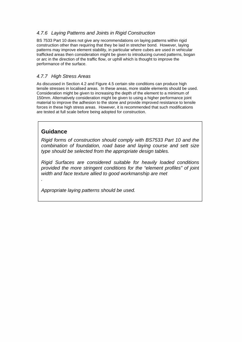
4.7.6 Laying Patterns and Joints in Rigid Construction BS 7533 Part 10 does not give any recommendations on laying patterns within rigid construction other than requiring that they be laid in stretcher bond. However, laying patterns may improve element stability, in particular where cubes are used in vehicular trafficked areas then consideration might be given to introducing curved patterns, bogan or arc in the direction of the traffic flow, or uphill which is thought to improve the performance of the surface.
4.7.7 High Stress Areas As discussed in Section 4.2 and Figure 4.5 certain site conditions can produce high tensile stresses in localised areas. In these areas, more stable elements should be used. Consideration might be given to increasing the depth of the element to a minimum of 150mm. Alternatively consideration might be given to using a higher performance joint material to improve the adhesion to the stone and provide improved resistance to tensile forces in these high stress areas. However, it is recommended that such modifications are tested at full scale before being adopted for construction.
Guidance Rigid forms of construction should comply with BS7533 Part 10 and thecombination of foundation, road base and laying course and sett sizetype should be selected from the appropriate design tables. Rigid Surfaces are considered suitable for heavily loaded conditionsprovided the more stringent conditions for the “element profiles” of jointwidth and face texture allied to good workmanship are met . Appropriate laying patterns should be used.

4.8 Analytical Design Approach
4.8.1 Principles of Analytical Design Approach The principles of the analytical approach to natural stone pavement design is the same as any other civil engineering structure; all parts of the structure should be operating within their performance capability. The basic approach with an analytical design is as follows.
• Quantify the loading. • Estimate the dimensions of components. • Consider the materials available. • Formulate an appropriate model. • Carry out a structural analysis using theoretical principles. • Compare critical stresses, strains, deflections or deformations with allowable
limits for materials. • Adjust material selections and / or dimensions of components to achieve a
satisfactory design. • Consider the economic feasibility of the result.
A flexible natural stone pavement behaves in a similar manner to that of an unbound road pavement. The effect of repeated surface applied stress results in deformation of the construction layers and the foundation. Failure conditions relate to unbound aggregate technology. A rigid natural stone pavement is more complex; the surface layer behaves in a similar manner to that of a concrete slab. The effect of repeated surface applied stress is to generate bending and shear stresses within the surface layer. With thin surface layer construction, elements less than 100mm depth, bending stresses are critical; cracking occurs which starts at the top surface of the layer. With thick surface layer construction joint shear stresses are critical; punching occurs which starts as a hairline crack around individual elements. There are two issues that are of critical importance in any analytical design procedure as follows: -
• Confidence in the properties of the materials used in the design • Validity of the analytical model
4.8.2 Material Properties The selection of the stone units themselves is dealt with in Section 3. Confidence in the properties of other materials used in the design can be achieved by consulting manufacturers detailed data sheets where available or through appropriate testing. The critical properties for the performance of a pavement are as follows: -
• Joint shear stress capacity under static loading. • Joint wall bond stress capacity under static loading. • Joint shear fatigue capacity (dynamic loading). • Joint wall bond fatigue capacity (dynamic loading). • Bedding compressive strength under static loading. • Bedding compressive fatigue strength (dynamic loading). • Characteristics of the structural support layers (stiffness modulus).
Limiting values of vertical shear stress in the joints of a surface layer can be defined from direct shear tests. Direct shear tests can be carried out on beams of stone elements cut from panels representative of the proposed surfacing. Alternatively shear tests can be carried out directly on the representative panels using a direct pull out test. The direct pull out test uses specialist equipment developed by Heriot-Watt University. In a structural design the fatigue shear strength should be defined. In the absence of direct testing of shear fatigue or specific correlation data it is necessary to make an approximation for the fatigue shear strength of a joint-stone system. This approximation is taken as one quarter of the single load shear strength. A load factor of 1.4 should be used as a factor of safety in the analytical model. The tensile strength of a surface layer is largely controlled by the joint wall bond capacity and can be defined from flexural tests on beams cut from representative test panels. Three or four-point bending tests are carried out on the beams. Data from a four-point bending test will be lower than that defined using a three point bending test, as occurs with flexural tests on concrete and mortar. A four-point beam test is the preferred method to define the tensile stress limit for a surface layer. As with shear strength unless direct fatigue testing data or correlation data is available a fatigue value of one quarter of the static load capacity should be applied. Again a load factor of 1.4 should be used as a factor of safety in a design. The bedding compressive strength and fatigue strength can be determined from standard mortar tests.
Guidance It is essential that the important properties of the constituent materials in a natural stone pavement are properly defined before an analytical model can be applied.
4.8.3 Analytical Model It is important that the analytical procedure that is adopted has been properly validated for the purpose of designing natural stone pavements and that its limitations in that respect are understood. Such validation can take the form of: -
• Comparison of predicted performance with that of existing designs where the as built conditions are known.
• Comparison of predicted performance with instrumented pavements. • Comparison of predicted performance with small and large scale testing results.
Failure to conduct appropriate validation will draw into question the results of the analytical approach and may lead to unforeseen failure of the resulting pavement structure. Two approaches are available for the design of a natural stone pavement: a two-stage simplified analysis of stress conditions within a pavement; or, a finite element analysis of the pavement structure as a whole. Of the two approaches the simplified analysis can at present only be applied to a rigid construction. With the two stage simplified analysis, the stress conditions in the surface layer are defined; vertical joint shear stress is the principal stress parameter. Assuming acceptable performance from the surface layer a linear elastic analysis is carried out on the structure as a whole. Appropriate limiting values for joint shear stress are required for the design of the surface layer. Appropriate values for the dynamic stiffness modulus of each construction layer are required for the pavement design, along with limiting values for the tensile stress at the bottom of the surface layer and any bound roadbase layer. In addition a limiting value for the vertical stress at the top of the sub-grade needs to be defined. In the finite element approach the pavement structure is analysed as a whole. The performance of the various layers is assessed in terms of the limiting stress and strain tolerances of the materials involved. The analytical design of a rigid structure provides an indefinite life, which means there will be no significant or progressive failure of a surface. To ensure that the results of the analytical design process are carried forward to the construction stage, the analytical design requires to be translated into a performance specification. Appropriate performance tests and limits need to be specified for the various components of the pavement.
Guidance Analytical models used for the design of natural stone pavements require to be validated for that specific purpose. The results of the design require to be translated into a performance specification.

4.9 Risk of Failure Model As the preceding sections have demonstrated there are many factors to consider in producing a successful natural stone paving design. Designing within the criteria given above should reduce the risk of failure. However an additional model has been developed to ensure that all of the elements of the design process have been considered correctly in the form of a risk assessment check sheet. The aim of the model is to provide a rapid check on the suitability of the design for its intended context. The model also considers some of the factors that are not quantified in the design process, such as workmanship. The basic structure of the risk assessment model presented in Appendix A is essentially a parametric analysis in which the most significant parameters influencing the performance of natural stone pavements are considered. The calculation process employed in the model derives a value that has been termed the Natural Stone Paving Failure Index. This model has been developed as part of the research project for SCOTS and is based on the experience and work of the project team. There are aspects of the model that will become better defined as knowledge of the behaviour of natural stone pavements advances. However, testing of the model with a range of current and past specifications has shown that it can provide a reliable indication of the risk of failure of a natural stone pavement. It must be stressed that this is a risk model, which only distinguishes between high and low risk of failure for natural stone pavements. It does not indicate that a pavement will or will not fail or when. By definition low-risk events can occur and high-risk events may not occur.
4.10 Other Design Consideration
4.10.1 Drainage There are two major objectives in the drainage of roads:
• The speedy removal of surface water to provide safety and minimum nuisance to all road users.
• Provision of effective sub-surface drainage to maximise longevity of the
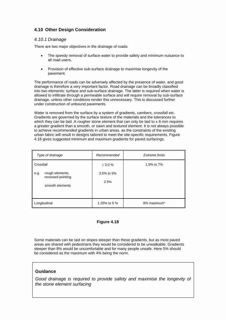
pavement. The performance of roads can be adversely affected by the presence of water, and good drainage is therefore a very important factor. Road drainage can be broadly classified into two elements: surface and sub-surface drainage. The latter is required when water is allowed to infiltrate through a permeable surface and will require removal by sub-surface drainage, unless other conditions render this unnecessary. This is discussed further under construction of unbound pavements. Water is removed from the surface by a system of gradients, cambers, crossfall etc. Gradients are governed by the surface texture of the materials and the tolerances to which they can be laid. A rougher stone element that can only be laid to ± 6 mm requires a greater gradient than a smooth, or sawn and textured element. It is not always possible to achieve recommended gradients in urban areas, as the constraints of the existing urban fabric will result in designs tailored to meet the site-specific requirements. Figure 4.18 gives suggested minimum and maximum gradients for paved surfacings.
Type of drainage Recommended Extreme limits
Crossfall
e.g. rough elements, recessed pointing
smooth elements
≥ 3.0 %
3.5% to 5%
2.5%
1.5% to 7%
Longitudinal 1.25% to 5 % 8% maximum*
Figure 4.18
Some materials can be laid on slopes steeper than these gradients, but as most paved areas are shared with pedestrians they would be considered to be unwalkable. Gradients steeper than 8% would be uncomfortable and for many people unsafe. Here 5% should be considered as the maximum with 4% being the norm.
Guidance Good drainage is required to provide safety and maximise the longevity ofthe stone element surfacing
4.10.2 Road Layout Road Width and Channelisation The selection of road width has an influence on costing, speed and increased loading. Lane widths less than the conventional 3.65 metres will produce a degree of channelisation. Where the traffic lane width reduces to 3.0m and less, full channelisation occurs, i.e. vehicle width restricts any lateral movement in the running lane and loading becomes concentrated over the same area. The effects of channelisation are allowed for in Figures 4.4 and 4.5 Overrun onto Pedestrian Areas Local knowledge should also be applied when available, e.g. vehicle over-run due to carriageway width or where delivery access to commercial properties is restricted. Road pavements are commonly designed in elevation or cross-section, but both aspects need to be considered at the same time in order to achieve the best performance and most economic pavement.
Guidance Allowances should be made in the design for channelisation effects and vehicle over-runs onto pedestrian areas.
4.10.3 Refurbishment Existing pavements can be overlaid with a stone element surfacing if the lower layers are structurally capable of carrying the anticipated traffic. It is also important that the support structure is compatible with the surface layer. If a flexible surface layer is being considered then the exiting lower layer should be capable of acting flexibly and if a rigid surface is being considered then it requires a rigid support structure. Indeed it may well be that the type of support available may determine the choice of surface type. An investigation is required to determine the properties of the existing roadbases. It is also necessary to determine that the lower support layers are at least equivalent to the allowable materials specified in the above design tables in terms of load carrying capacity. This is particularly so in the case where support layers have to be reduced in depth to accommodate the increased thickness of the stone surface layer. An investigation will also provide valuable information on the location and depth of existing services. Renewal of services can often have an impact on the feasibility of retaining support layers. If extensive service renewal or diversions are required then extensive disruption to the support layer would occur and it may be wiser to renew these layers entirely. An investigation should include the following:
• Desk study. • Visual assessment. • Level survey. • Falling Weight Deflectometer (FWD) survey. • Coring and Dynamic Cone Penetrometer (DCP) tests (optional). • Ground Penetrating Radar survey (optional). • Materials Testing. • Analysis, interpretation and reporting.
Typically, surface materials are removed from an existing road to expose either a concrete or asphalt roadbase and its conditions has to be assessed.
Condition of Existing Asphalt - The Design Manual for Roads and Bridges (DMRB), Volume 7 gives comprehensive guidance on the pavement assessment techniques that are available. The Falling Weight Deflectometer (FWD) should be used to obtain information about the pavement condition to determine whether it is suitable for overlay in terms of stiffness compatibility and strength. Coring will determine layer thickness and assist in assessing the condition of the material. Condition of Existing Concrete - Similarly, the DMRB gives guidance on assessing the condition of concrete. The FWD can be used in this instance to determine whether load transfer at joints and cracks is adequate. This is assessed by loading the concrete slab on one side and measuring the deflections on each side of the joint or crack. Poor load transfer indicates deterioration and wash out and will require repair. In addition to the DMRB the Manual for the maintenance and repair of concrete roads (Mildenhall HS, 1986) gives practical advice on how to repair the slabs through various grouting techniques. Cores should be taken to determine depth and compressive strength of the concrete.
Guidance A site investigation is required to determine whether existing supportlayers are adequate for overlay in terms of levels, stiffness compatibilityand load carrying capacity. The remaining support layers must be at least equivalent in load carrying capacity to the materials specified in the design standards. Methods of assessing the condition and properties of existing supportlayers are available in the current roads standards.
4.10.4 Services Where possible new paved roads should be designed so that services can run in footways. If this is not possible the provision of service ducts minimises disruption during maintenance work. Recommendations on positioning new services are contained in the NJUG Publication Number 7, 1986. The depth of services can be a particular problem and consultation with public utility (PU) operators is essential at the design stage. For example, bound or rigid pavements in heavily trafficked areas suffer greatly on being opened up for access to services. Expensive repairs causing traffic delays will result. Maintenance problems are also likely to be encountered with a road that has been trenched and then refilled. It is therefore recommended that where possible services are relocated to areas, which are not carrying vehicular traffic. Further advice is given in Section 8.
Guidance If possible new paved roads should be designed so that services can run in footways. Consultation with PU operators is essential at the design stage.
4.11 Detailing All pavements consist of a variety of materials and forms of construction, which require careful detailing. Substantial additional expenditure is often required to repair defects caused by poor initial detailing of stone elements or by lack of thought at the design stage. Careful attention should be give to the following aspects:
• Edge details. • Change of surfacing. • Street furniture. • Thermal movement.
4.11.1 Edge Details Robust edge details are required to support and restrain paved surfaces. For a flexible stone construction, edge details are critically important. The spreading of loads through the action of interlock and friction produces horizontal forces that require to be resisted at the edges of the pavement. A robust edge construction must be provided to resist the horizontal forces and allow the interlock forces to be mobilised. Kerbing or other edging, laid and haunched on a concrete bed of at least 0.1m3 per linear metre is required to provide enough weight to give the necessary restraint. A typical edge detail is shown in Appendix B.
4.11.2 Change of Surface Problems are often encountered at the interface between a stone paved surfacing and an asphaltic road construction. This is commonly as a result of differential material responses to temperature variations that cause de-bonding and subsequent failure of joints in the stone surface. The effect is progressive under cycles of trafficking and weather. Appendix B shows a detail, which aims to minimise cracking by confining it to the wearing course of the asphaltic pavement.
4.11.3 Street Furniture and Ironwork Details around street furniture in particular ironwork in the surface, which are over run by traffic, are critical with a rigid surface layer construction. Access shafts for manholes, toby covers and the like; respond differently to loading compared to a rigid pavement construction. This differential response can lead to fracture in the joints of the stone surface adjacent to the item of street furniture. Consideration should be given to the detailing here to provide a more robust surface with perhaps a more resilient joint filling medium, such as polyurethane bound joint mixture. The joint mixture should provide a degree of elasticity to accommodate the differential response. Where secondary compaction is likely to occur around street furniture, a more appropriate solution may be to introduce a flexible construction surface layer adjacent to the street furniture. A suitable detail will be required between the small area of flexible surface and the main rigid surface. Problems can also be encountered with recessed service access covers that incorporate paving materials. If this detail is to be used it is recommended that all infill stone units be bedded on an appropriate mortar, e.g. polyester resin, to prevent them working loose,
4.11.4 Movement joints With cement-stabilised road-bases, expansion and contraction of this layer requires to be considered (see Section 8). Stone Units are normally deeper than the corresponding layers in other forms of construction. This means that the cementatious materials might not be subject to the same temperature effects, which might mean that the induced thermal stresses will not cause the slab to crack. The designer has to consider carefully if the road base will require contraction or expansion joints.
When thermal effects are likely to occur, contraction joints should be detailed into the roadbase at 8-10m centres. Expansion joints, where required, should be located every third contraction joint. There are many appropriate details for these types of joints in concrete and the current road standards allow several options depending on a number of specific construction factors. With a pavement-quality roadbase dowel bars should be considered across the expansion, contraction and construction joints to ensure shear continuity. A movement joint in the surface layer is required above any joint in the roadbase. Within the surface layer containment of the stone elements is critical at a joint. This may be achieved using stainless steel angle sections bolted to a concrete roadbase. An alternative solution is to use a low stiffness modulus polyurethane bound aggregate to fill the joints. The toughness of the polyurethane allows the roadbase to move and the joint remain sealed, whilst adequate confinement of the stone elements is provided.
Guidance Careful attention should be given to the detailing of edge details, changes of surfacing and installation of street furniture. Where thermal effects are likely to occur in the concrete road bases and base-courses, the potential for cracking of the concrete should be controlled by incorporating movement joints, designed in accordance with current road standards.


![4.1.3 Geología[1] - Infiltración Prueba](https://img.pdfslide.net/doc/110x75/577c781a1a28abe0548ebcc4/413-geologia1-infiltracion-prueba.jpg)