Embed Size (px)
Citation preview
January 2003 California Stormwater BMP Handbook 4-1 Errata 9-04 New Development and Redevelopment www.cabmphandbooks.com
Section 4 Source Control BMPs 4.1 Introduction This section describes specific source control Best Management Practices (BMPs) to be considered for incorporation into newly developed public and private infrastructure, as well as retrofit into existing facilities to meet stormwater management objectives.
4.2 BMP Fact Sheets Source control fact sheets for design are listed in Table 4-1. The fact sheets detail planning methods and concepts that should be taken into consideration by developers during project design. The fact sheets are arranged in three categories: those that have to do with landscape, irrigation, and signage considerations; those that have to do with use of particular materials; and those that have to do with design of particular areas.
4.3 Fact Sheet Format A BMP fact sheet is a short document that provides information about a particular BMP. Typically, each fact sheet contains the information outlined in Figure 4-1. Supplemental information is provided if it is available. The fact sheets also contain side bar presentations with information on BMP design objectives. Completed fact sheets for each of the above activities are provided in Section 4.4.
4.4 BMP Fact Sheets Source Control BMP Fact Sheets for design follow. The BMP fact sheets are individually page numbered and are suitable for photocopying and inclusion in stormwater quality management plans. Fresh copies of the fact sheets can be individually downloaded from the California Stormwater BMP Handbook website at www.cabmphandbooks.com.
Table 4-1 Source Control BMPs for Design
Design
SD-10 Site Design and Landscape Planning
SD-11 Roof Runoff Controls
SD-12 Efficient Irrigation
SD-13 Storm Drain System Signs
Materials
SD-20 Pervious Pavements
SD-21 Alternative Building Materials
Areas
SD-30 Fueling Areas
SD-31 Maintenance Bays and Docks
SD-32 Trash Enclosures
SD-33 Vehicle Washing Areas
SD-34 Outdoor Material Storage Areas
SD-35 Outdoor Work Areas
SD-36 Outdoor Processing Areas
SDxx Example Fact Sheet
Description of the BMP
Approach
Suitable Applications
Design Considerations
Designing New Installations
Redeveloping Existing Installations
Supplemental Information
Examples
Other Resources
Figure 4-1Example Fact Sheet

Site Design & Landscape Planning SD-10
January 2003 California Stormwater BMP Handbook 1 of 4 New Development and Redevelopment www.cabmphandbooks.com
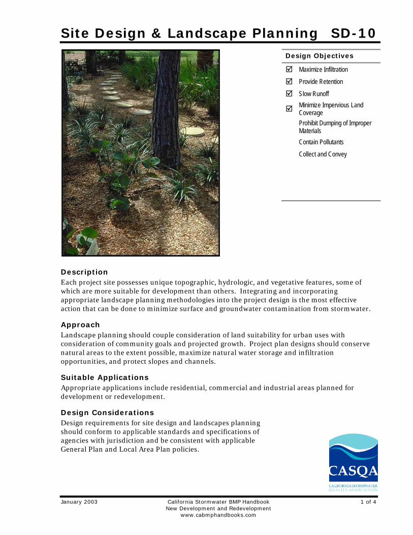
Description Each project site possesses unique topographic, hydrologic, and vegetative features, some of which are more suitable for development than others. Integrating and incorporating appropriate landscape planning methodologies into the project design is the most effective action that can be done to minimize surface and groundwater contamination from stormwater.
Approach Landscape planning should couple consideration of land suitability for urban uses with consideration of community goals and projected growth. Project plan designs should conserve natural areas to the extent possible, maximize natural water storage and infiltration opportunities, and protect slopes and channels.
Suitable Applications Appropriate applications include residential, commercial and industrial areas planned for development or redevelopment.
Design Considerations Design requirements for site design and landscapes planning should conform to applicable standards and specifications of agencies with jurisdiction and be consistent with applicable General Plan and Local Area Plan policies.
Design Objectives
Maximize Infiltration
Provide Retention
Slow Runoff
Minimize Impervious Land Coverage
Prohibit Dumping of Improper Materials
Contain Pollutants
Collect and Convey
SD-10 Site Design & Landscape Planning
2 of 4 California Stormwater BMP Handbook January 2003 New Development and Redevelopment www.cabmphandbooks.com
Designing New Installations Begin the development of a plan for the landscape unit with attention to the following general principles:
Formulate the plan on the basis of clearly articulated community goals. Carefully identify conflicts and choices between retaining and protecting desired resources and community growth.
Map and assess land suitability for urban uses. Include the following landscape features in the assessment: wooded land, open unwooded land, steep slopes, erosion-prone soils, foundation suitability, soil suitability for waste disposal, aquifers, aquifer recharge areas, wetlands, floodplains, surface waters, agricultural lands, and various categories of urban land use. When appropriate, the assessment can highlight outstanding local or regional resources that the community determines should be protected (e.g., a scenic area, recreational area, threatened species habitat, farmland, fish run). Mapping and assessment should recognize not only these resources but also additional areas needed for their sustenance.
Project plan designs should conserve natural areas to the extent possible, maximize natural water storage and infiltration opportunities, and protect slopes and channels.
Conserve Natural Areas during Landscape Planning
If applicable, the following items are required and must be implemented in the site layout during the subdivision design and approval process, consistent with applicable General Plan and Local Area Plan policies:
Cluster development on least-sensitive portions of a site while leaving the remaining land in a natural undisturbed condition.
Limit clearing and grading of native vegetation at a site to the minimum amount needed to build lots, allow access, and provide fire protection.
Maximize trees and other vegetation at each site by planting additional vegetation, clustering tree areas, and promoting the use of native and/or drought tolerant plants.
Promote natural vegetation by using parking lot islands and other landscaped areas.
Preserve riparian areas and wetlands.
Maximize Natural Water Storage and Infiltration Opportunities Within the Landscape Unit
Promote the conservation of forest cover. Building on land that is already deforested affects basin hydrology to a lesser extent than converting forested land. Loss of forest cover reduces interception storage, detention in the organic forest floor layer, and water losses by evapotranspiration, resulting in large peak runoff increases and either their negative effects or the expense of countering them with structural solutions.
Maintain natural storage reservoirs and drainage corridors, including depressions, areas of permeable soils, swales, and intermittent streams. Develop and implement policies and
Site Design & Landscape Planning SD-10
January 2003 California Stormwater BMP Handbook 3 of 4 New Development and Redevelopment www.cabmphandbooks.com
regulations to discourage the clearing, filling, and channelization of these features. Utilize them in drainage networks in preference to pipes, culverts, and engineered ditches.
Evaluating infiltration opportunities by referring to the stormwater management manual for the jurisdiction and pay particular attention to the selection criteria for avoiding groundwater contamination, poor soils, and hydrogeological conditions that cause these facilities to fail. If necessary, locate developments with large amounts of impervious surfaces or a potential to produce relatively contaminated runoff away from groundwater recharge areas.
Protection of Slopes and Channels during Landscape Design
Convey runoff safely from the tops of slopes.
Avoid disturbing steep or unstable slopes.
Avoid disturbing natural channels.
Stabilize disturbed slopes as quickly as possible.
Vegetate slopes with native or drought tolerant vegetation.
Control and treat flows in landscaping and/or other controls prior to reaching existing natural drainage systems.
Stabilize temporary and permanent channel crossings as quickly as possible, and ensure that increases in run-off velocity and frequency caused by the project do not erode the channel.
Install energy dissipaters, such as riprap, at the outlets of new storm drains, culverts, conduits, or channels that enter unlined channels in accordance with applicable specifications to minimize erosion. Energy dissipaters shall be installed in such a way as to minimize impacts to receiving waters.
Line on-site conveyance channels where appropriate, to reduce erosion caused by increased flow velocity due to increases in tributary impervious area. The first choice for linings should be grass or some other vegetative surface, since these materials not only reduce runoff velocities, but also provide water quality benefits from filtration and infiltration. If velocities in the channel are high enough to erode grass or other vegetative linings, riprap, concrete, soil cement, or geo-grid stabilization are other alternatives.
Consider other design principles that are comparable and equally effective.
Redeveloping Existing Installations Various jurisdictional stormwater management and mitigation plans (SUSMP, WQMP, etc.) define “redevelopment” in terms of amounts of additional impervious area, increases in gross floor area and/or exterior construction, and land disturbing activities with structural or impervious surfaces. The definition of “ redevelopment” must be consulted to determine whether or not the requirements for new development apply to areas intended for redevelopment. If the definition applies, the steps outlined under “designing new installations” above should be followed.
SD-10 Site Design & Landscape Planning
4 of 4 California Stormwater BMP Handbook January 2003 New Development and Redevelopment www.cabmphandbooks.com
Redevelopment may present significant opportunity to add features which had not previously been implemented. Examples include incorporation of depressions, areas of permeable soils, and swales in newly redeveloped areas. While some site constraints may exist due to the status of already existing infrastructure, opportunities should not be missed to maximize infiltration, slow runoff, reduce impervious areas, disconnect directly connected impervious areas.
Other Resources A Manual for the Standard Urban Stormwater Mitigation Plan (SUSMP), Los Angeles County Department of Public Works, May 2002.
Stormwater Management Manual for Western Washington, Washington State Department of Ecology, August 2001.
Model Standard Urban Storm Water Mitigation Plan (SUSMP) for San Diego County, Port of San Diego, and Cities in San Diego County, February 14, 2002.
Model Water Quality Management Plan (WQMP) for County of Orange, Orange County Flood Control District, and the Incorporated Cities of Orange County, Draft February 2003.
Ventura Countywide Technical Guidance Manual for Stormwater Quality Control Measures, July 2002.
Roof Runoff Controls SD-11
January 2003 California Stormwater BMP Handbook 1 of 3 New Development and Redevelopment www.cabmphandbook.com
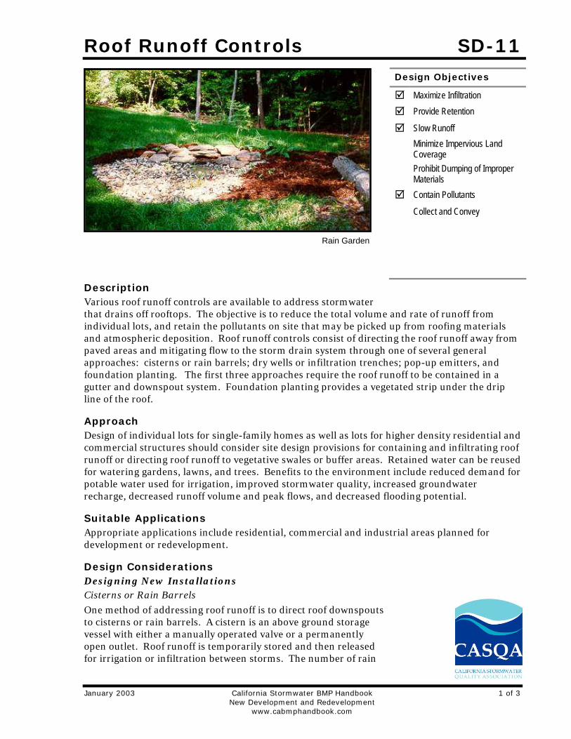
Description Various roof runoff controls are available to address stormwater that drains off rooftops. The objective is to reduce the total volume and rate of runoff from individual lots, and retain the pollutants on site that may be picked up from roofing materials and atmospheric deposition. Roof runoff controls consist of directing the roof runoff away from paved areas and mitigating flow to the storm drain system through one of several general approaches: cisterns or rain barrels; dry wells or infiltration trenches; pop-up emitters, and foundation planting. The first three approaches require the roof runoff to be contained in a gutter and downspout system. Foundation planting provides a vegetated strip under the drip line of the roof.
Approach Design of individual lots for single-family homes as well as lots for higher density residential and commercial structures should consider site design provisions for containing and infiltrating roof runoff or directing roof runoff to vegetative swales or buffer areas. Retained water can be reused for watering gardens, lawns, and trees. Benefits to the environment include reduced demand for potable water used for irrigation, improved stormwater quality, increased groundwater recharge, decreased runoff volume and peak flows, and decreased flooding potential.
Suitable Applications Appropriate applications include residential, commercial and industrial areas planned for development or redevelopment.
Design Considerations Designing New Installations Cisterns or Rain Barrels
One method of addressing roof runoff is to direct roof downspouts to cisterns or rain barrels. A cistern is an above ground storage vessel with either a manually operated valve or a permanently open outlet. Roof runoff is temporarily stored and then released for irrigation or infiltration between storms. The number of rain
Design Objectives
Maximize Infiltration
Provide Retention
Slow Runoff
Minimize Impervious Land Coverage
Prohibit Dumping of Improper Materials
Contain Pollutants
Collect and Convey
Rain Garden
SD-11 Roof Runoff Controls
2 of 3 California Stormwater BMP Handbook January 2003 New Development and Redevelopment www.cabmphandbook.com
barrels needed is a function of the rooftop area. Some low impact developers recommend that every house have at least 2 rain barrels, with a minimum storage capacity of 1000 liters. Roof barrels serve several purposes including mitigating the first flush from the roof which has a high volume, amount of contaminants, and thermal load. Several types of rain barrels are commercially available. Consideration must be given to selecting rain barrels that are vector proof and childproof. In addition, some barrels are designed with a bypass valve that filters out grit and other contaminants and routes overflow to a soak-away pit or rain garden.
If the cistern has an operable valve, the valve can be closed to store stormwater for irrigation or infiltration between storms. This system requires continual monitoring by the resident or grounds crews, but provides greater flexibility in water storage and metering. If a cistern is provided with an operable valve and water is stored inside for long periods, the cistern must be covered to prevent mosquitoes from breeding.
A cistern system with a permanently open outlet can also provide for metering stormwater runoff. If the cistern outlet is significantly smaller than the size of the downspout inlet (say ¼ to ½ inch diameter), runoff will build up inside the cistern during storms, and will empty out slowly after peak intensities subside. This is a feasible way to mitigate the peak flow increases caused by rooftop impervious land coverage, especially for the frequent, small storms.
Dry wells and Infiltration Trenches
Roof downspouts can be directed to dry wells or infiltration trenches. A dry well is constructed by excavating a hole in the ground and filling it with an open graded aggregate, and allowing the water to fill the dry well and infiltrate after the storm event. An underground connection from the downspout conveys water into the dry well, allowing it to be stored in the voids. To minimize sedimentation from lateral soil movement, the sides and top of the stone storage matrix can be wrapped in a permeable filter fabric, though the bottom may remain open. A perforated observation pipe can be inserted vertically into the dry well to allow for inspection and maintenance.
In practice, dry wells receiving runoff from single roof downspouts have been successful over long periods because they contain very little sediment. They must be sized according to the amount of rooftop runoff received, but are typically 4 to 5 feet square, and 2 to 3 feet deep, with a minimum of 1-foot soil cover over the top (maximum depth of 10 feet).
To protect the foundation, dry wells must be set away from the building at least 10 feet. They must be installed in solids that accommodate infiltration. In poorly drained soils, dry wells have very limited feasibility.
Infiltration trenches function in a similar manner and would be particularly effective for larger roof areas. An infiltration trench is a long, narrow, rock-filled trench with no outlet that receives stormwater runoff. These are described under Treatment Controls.
Pop-up Drainage Emitter
Roof downspouts can be directed to an underground pipe that daylights some distance from the building foundation, releasing the roof runoff through a pop-up emitter. Similar to a pop-up irrigation head, the emitter only opens when there is flow from the roof. The emitter remains flush to the ground during dry periods, for ease of lawn or landscape maintenance.
Roof Runoff Controls SD-11
January 2003 California Stormwater BMP Handbook 3 of 3 New Development and Redevelopment www.cabmphandbook.com
Foundation Planting
Landscape planting can be provided around the base to allow increased opportunities for stormwater infiltration and protect the soil from erosion caused by concentrated sheet flow coming off the roof. Foundation plantings can reduce the physical impact of water on the soil and provide a subsurface matrix of roots that encourage infiltration. These plantings must be sturdy enough to tolerate the heavy runoff sheet flows, and periodic soil saturation.
Redeveloping Existing Installations Various jurisdictional stormwater management and mitigation plans (SUSMP, WQMP, etc.) define “redevelopment” in terms of amounts of additional impervious area, increases in gross floor area and/or exterior construction, and land disturbing activities with structural or impervious surfaces. The definition of “ redevelopment” must be consulted to determine whether or not the requirements for new development apply to areas intended for redevelopment. If the definition applies, the steps outlined under “designing new installations” above should be followed.
Supplemental Information Examples
City of Ottawa’s Water Links Surface –Water Quality Protection Program
City of Toronto Downspout Disconnection Program
City of Boston, MA, Rain Barrel Demonstration Program
Other Resources Hager, Marty Catherine, Stormwater, “Low-Impact Development”, January/February 2003. www.stormh2o.com
Low Impact Urban Design Tools, Low Impact Development Design Center, Beltsville, MD. www.lid-stormwater.net
Start at the Source, Bay Area Stormwater Management Agencies Association, 1999 Edition

Efficient Irrigation SD-12
January 2003 California Stormwater BMP Handbook 1 of 2 New Development and Redevelopment www.cabmphandbooks.com
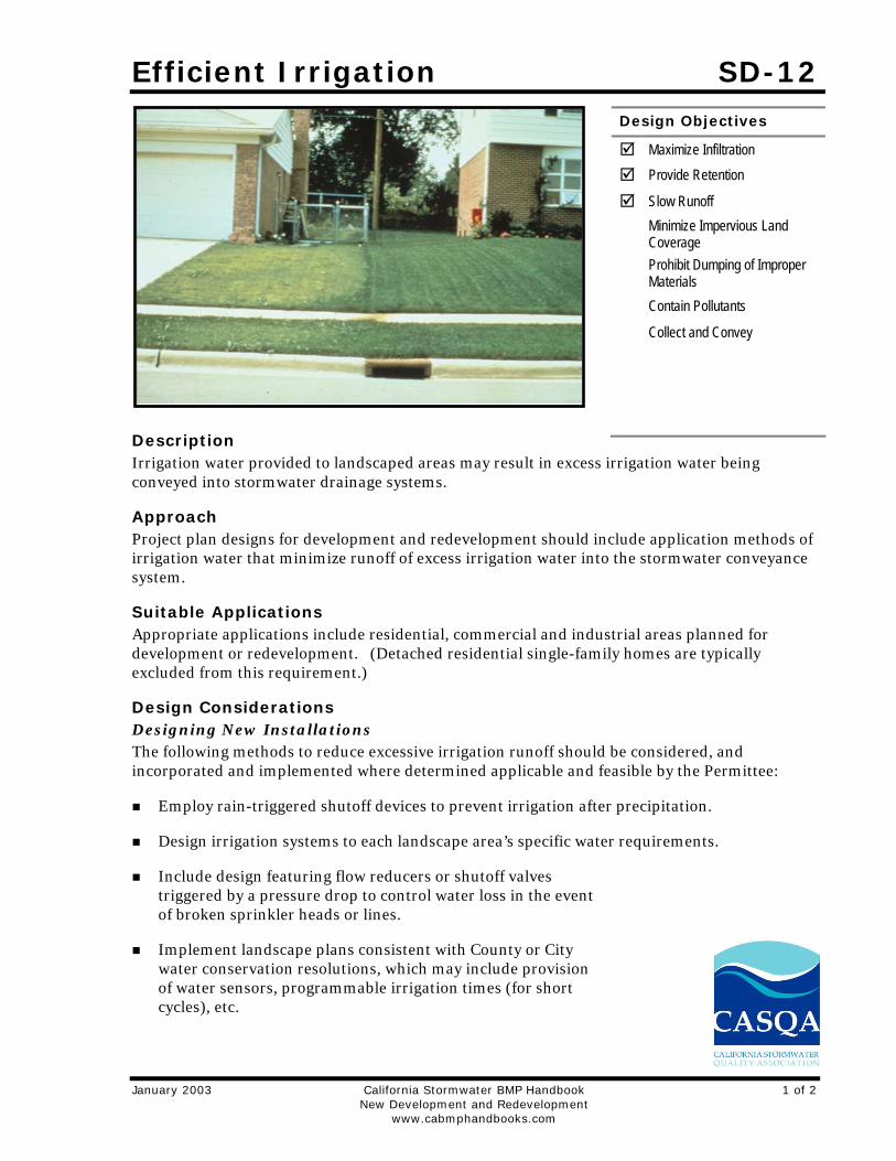
Description Irrigation water provided to landscaped areas may result in excess irrigation water being conveyed into stormwater drainage systems.
Approach Project plan designs for development and redevelopment should include application methods of irrigation water that minimize runoff of excess irrigation water into the stormwater conveyance system.
Suitable Applications Appropriate applications include residential, commercial and industrial areas planned for development or redevelopment. (Detached residential single-family homes are typically excluded from this requirement.)
Design Considerations Designing New Installations The following methods to reduce excessive irrigation runoff should be considered, and incorporated and implemented where determined applicable and feasible by the Permittee:
Employ rain-triggered shutoff devices to prevent irrigation after precipitation.
Design irrigation systems to each landscape area’s specific water requirements.
Include design featuring flow reducers or shutoff valves triggered by a pressure drop to control water loss in the event of broken sprinkler heads or lines.
Implement landscape plans consistent with County or City water conservation resolutions, which may include provision of water sensors, programmable irrigation times (for short cycles), etc.
Design Objectives
Maximize Infiltration
Provide Retention
Slow Runoff
Minimize Impervious Land Coverage
Prohibit Dumping of Improper Materials
Contain Pollutants
Collect and Convey
SD-12 Efficient Irrigation
2 of 2 California Stormwater BMP Handbook January 2003 New Development and Redevelopment www.cabmphandbooks.com
Design timing and application methods of irrigation water to minimize the runoff of excess irrigation water into the storm water drainage system.
Group plants with similar water requirements in order to reduce excess irrigation runoff and promote surface filtration. Choose plants with low irrigation requirements (for example, native or drought tolerant species). Consider design features such as:
- Using mulches (such as wood chips or bar) in planter areas without ground cover to minimize sediment in runoff
- Installing appropriate plant materials for the location, in accordance with amount of sunlight and climate, and use native plant materials where possible and/or as recommended by the landscape architect
- Leaving a vegetative barrier along the property boundary and interior watercourses, to act as a pollutant filter, where appropriate and feasible
- Choosing plants that minimize or eliminate the use of fertilizer or pesticides to sustain growth
Employ other comparable, equally effective methods to reduce irrigation water runoff.
Redeveloping Existing Installations Various jurisdictional stormwater management and mitigation plans (SUSMP, WQMP, etc.) define “redevelopment” in terms of amounts of additional impervious area, increases in gross floor area and/or exterior construction, and land disturbing activities with structural or impervious surfaces. The definition of “ redevelopment” must be consulted to determine whether or not the requirements for new development apply to areas intended for redevelopment. If the definition applies, the steps outlined under “designing new installations” above should be followed.
Other Resources A Manual for the Standard Urban Stormwater Mitigation Plan (SUSMP), Los Angeles County Department of Public Works, May 2002.
Model Standard Urban Storm Water Mitigation Plan (SUSMP) for San Diego County, Port of San Diego, and Cities in San Diego County, February 14, 2002.
Model Water Quality Management Plan (WQMP) for County of Orange, Orange County Flood Control District, and the Incorporated Cities of Orange County, Draft February 2003.
Ventura Countywide Technical Guidance Manual for Stormwater Quality Control Measures, July 2002.
Storm Drain Signage SD-13
January 2003 California Stormwater BMP Handbook 1 of 2 New Development and Redevelopment www.cabmphandbooks.com
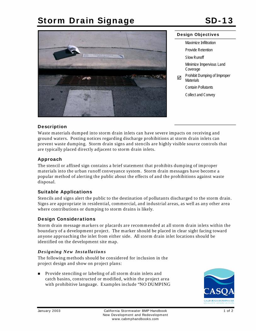
Description Waste materials dumped into storm drain inlets can have severe impacts on receiving and ground waters. Posting notices regarding discharge prohibitions at storm drain inlets can prevent waste dumping. Storm drain signs and stencils are highly visible source controls that are typically placed directly adjacent to storm drain inlets.
Approach The stencil or affixed sign contains a brief statement that prohibits dumping of improper materials into the urban runoff conveyance system. Storm drain messages have become a popular method of alerting the public about the effects of and the prohibitions against waste disposal.
Suitable Applications Stencils and signs alert the public to the destination of pollutants discharged to the storm drain. Signs are appropriate in residential, commercial, and industrial areas, as well as any other area where contributions or dumping to storm drains is likely.
Design Considerations Storm drain message markers or placards are recommended at all storm drain inlets within the boundary of a development project. The marker should be placed in clear sight facing toward anyone approaching the inlet from either side. All storm drain inlet locations should be identified on the development site map.
Designing New Installations The following methods should be considered for inclusion in the project design and show on project plans:
Provide stenciling or labeling of all storm drain inlets and catch basins, constructed or modified, within the project area with prohibitive language. Examples include “NO DUMPING
Design Objectives
Maximize Infiltration
Provide Retention
Slow Runoff
Minimize Impervious Land Coverage
Prohibit Dumping of Improper Materials
Contain Pollutants
Collect and Convey
SD-13 Storm Drain Signage
2 of 2 California Stormwater BMP Handbook January 2003 New Development and Redevelopment www.cabmphandbooks.com
– DRAINS TO OCEAN” and/or other graphical icons to discourage illegal dumping.
Post signs with prohibitive language and/or graphical icons, which prohibit illegal dumping at public access points along channels and creeks within the project area.
Note - Some local agencies have approved specific signage and/or storm drain message placards for use. Consult local agency stormwater staff to determine specific requirements for placard types and methods of application.
Redeveloping Existing Installations Various jurisdictional stormwater management and mitigation plans (SUSMP, WQMP, etc.) define “redevelopment” in terms of amounts of additional impervious area, increases in gross floor area and/or exterior construction, and land disturbing activities with structural or impervious surfaces. If the project meets the definition of “redevelopment”, then the requirements stated under “ designing new installations” above should be included in all project design plans.
Additional Information Maintenance Considerations
Legibility of markers and signs should be maintained. If required by the agency with jurisdiction over the project, the owner/operator or homeowner’s association should enter into a maintenance agreement with the agency or record a deed restriction upon the property title to maintain the legibility of placards or signs.
Placement Signage on top of curbs tends to weather and fade.
Signage on face of curbs tends to be worn by contact with vehicle tires and sweeper brooms.
Supplemental Information Examples
Most MS4 programs have storm drain signage programs. Some MS4 programs will provide stencils, or arrange for volunteers to stencil storm drains as part of their outreach program.
Other Resources A Manual for the Standard Urban Stormwater Mitigation Plan (SUSMP), Los Angeles County Department of Public Works, May 2002.
Model Standard Urban Storm Water Mitigation Plan (SUSMP) for San Diego County, Port of San Diego, and Cities in San Diego County, February 14, 2002.
Model Water Quality Management Plan (WQMP) for County of Orange, Orange County Flood Control District, and the Incorporated Cities of Orange County, Draft February 2003.
Ventura Countywide Technical Guidance Manual for Stormwater Quality Control Measures, July 2002.
Pervious Pavements SD-20
January 2003 California Stormwater BMP Handbook 1 of 10 New Development and Redevelopment www.cabmphandbooks.com
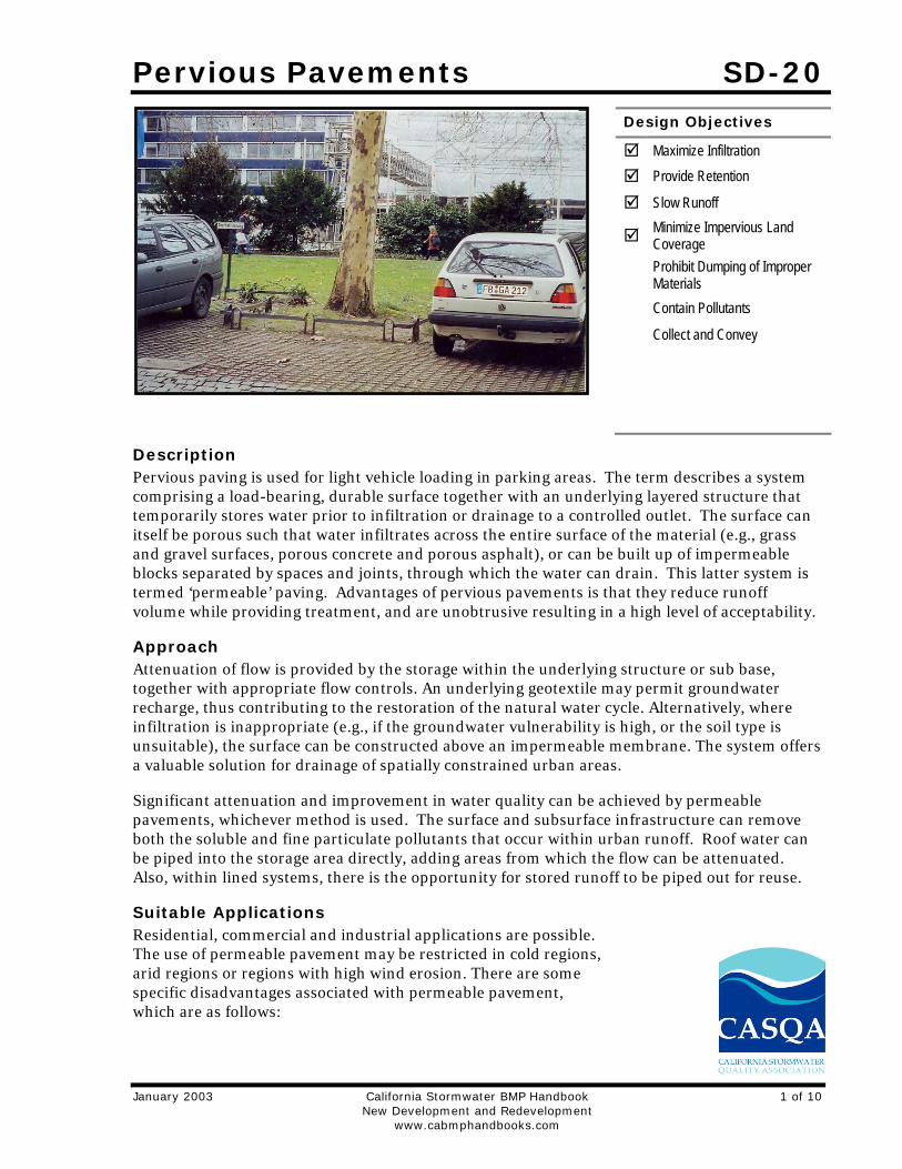
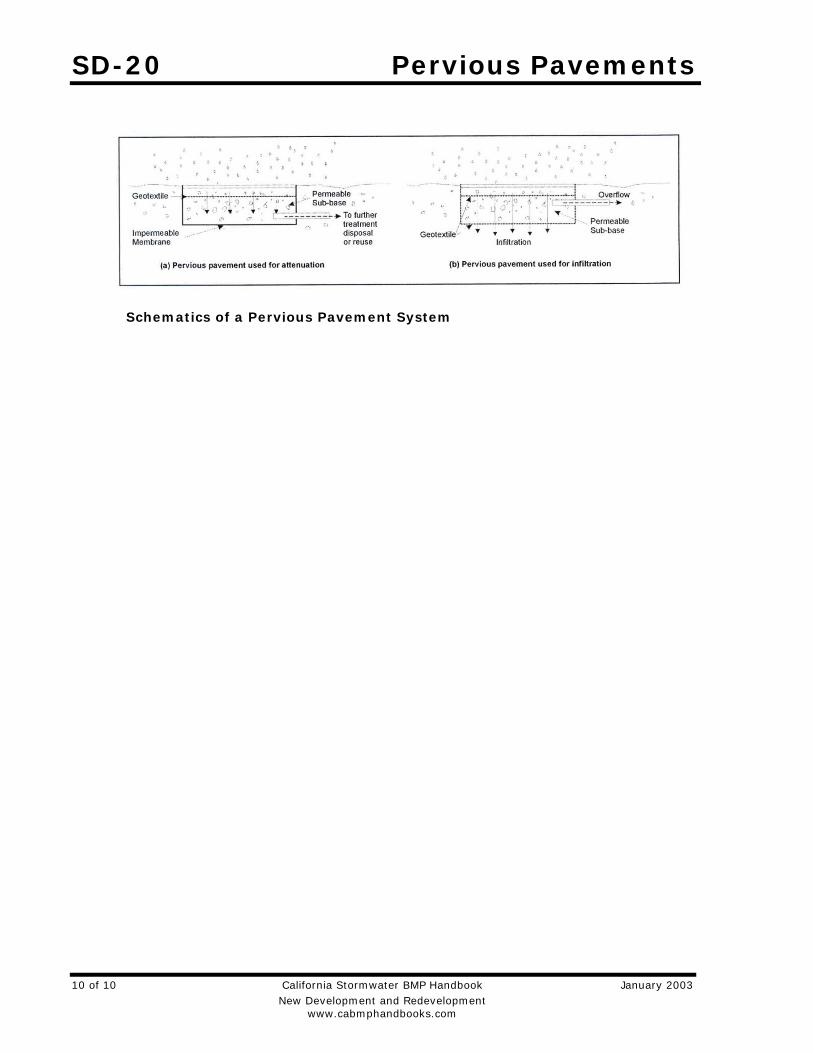
Description Pervious paving is used for light vehicle loading in parking areas. The term describes a system comprising a load-bearing, durable surface together with an underlying layered structure that temporarily stores water prior to infiltration or drainage to a controlled outlet. The surface can itself be porous such that water infiltrates across the entire surface of the material (e.g., grass and gravel surfaces, porous concrete and porous asphalt), or can be built up of impermeable blocks separated by spaces and joints, through which the water can drain. This latter system is termed ‘permeable’ paving. Advantages of pervious pavements is that they reduce runoff volume while providing treatment, and are unobtrusive resulting in a high level of acceptability.
Approach Attenuation of flow is provided by the storage within the underlying structure or sub base, together with appropriate flow controls. An underlying geotextile may permit groundwater recharge, thus contributing to the restoration of the natural water cycle. Alternatively, where infiltration is inappropriate (e.g., if the groundwater vulnerability is high, or the soil type is unsuitable), the surface can be constructed above an impermeable membrane. The system offers a valuable solution for drainage of spatially constrained urban areas.
Significant attenuation and improvement in water quality can be achieved by permeable pavements, whichever method is used. The surface and subsurface infrastructure can remove both the soluble and fine particulate pollutants that occur within urban runoff. Roof water can be piped into the storage area directly, adding areas from which the flow can be attenuated. Also, within lined systems, there is the opportunity for stored runoff to be piped out for reuse.
Suitable Applications Residential, commercial and industrial applications are possible. The use of permeable pavement may be restricted in cold regions, arid regions or regions with high wind erosion. There are some specific disadvantages associated with permeable pavement, which are as follows:
Design Objectives
Maximize Infiltration
Provide Retention
Slow Runoff
Minimize Impervious Land Coverage
Prohibit Dumping of Improper Materials
Contain Pollutants
Collect and Convey
SD-20 Pervious Pavements
2 of 10 California Stormwater BMP Handbook January 2003 New Development and Redevelopment www.cabmphandbooks.com
Permeable pavement can become clogged if improperly installed or maintained. However, this is countered by the ease with which small areas of paving can be cleaned or replaced when blocked or damaged.
Their application should be limited to highways with low traffic volumes, axle loads and speeds (less than 30 mph limit), car parking areas and other lightly trafficked or non-trafficked areas. Permeable surfaces are currently not considered suitable for adoptable roads due to the risks associated with failure on high speed roads, the safety implications of ponding, and disruption arising from reconstruction.
When using un-lined, infiltration systems, there is some risk of contaminating groundwater, depending on soil conditions and aquifer susceptibility. However, this risk is likely to be small because the areas drained tend to have inherently low pollutant loadings.
The use of permeable pavement is restricted to gentle slopes.
Porous block paving has a higher risk of abrasion and damage than solid blocks.
Design Considerations Designing New Installations If the grades, subsoils, drainage characteristics, and groundwater conditions are suitable, permeable paving may be substituted for conventional pavement on parking areas, cul de sacs and other areas with light traffic. Slopes should be flat or very gentle. Scottish experience has shown that permeable paving systems can be installed in a wide range of ground conditions, and the flow attenuation performance is excellent even when the systems are lined.
The suitability of a pervious system at a particular pavement site will, however, depend on the loading criteria required of the pavement.
Where the system is to be used for infiltrating drainage waters into the ground, the vulnerability of local groundwater sources to pollution from the site should be low, and the seasonal high water table should be at least 4 feet below the surface.
Ideally, the pervious surface should be horizontal in order to intercept local rainfall at source. On sloping sites, pervious surfaces may be terraced to accommodate differences in levels.
Design Guidelines The design of each layer of the pavement must be determined by the likely traffic loadings and their required operational life. To provide satisfactory performance, the following criteria should be considered:
The subgrade should be able to sustain traffic loading without excessive deformation.
The granular capping and sub-base layers should give sufficient load-bearing to provide an adequate construction platform and base for the overlying pavement layers.
The pavement materials should not crack of suffer excessive rutting under the influence of traffic. This is controlled by the horizontal tensile stress at the base of these layers.
Pervious Pavements SD-20
January 2003 California Stormwater BMP Handbook 3 of 10 New Development and Redevelopment www.cabmphandbooks.com
There is no current structural design method specifically for pervious pavements. Allowances should be considered the following factors in the design and specification of materials:
Pervious pavements use materials with high permeability and void space. All the current UK pavement design methods are based on the use of conventional materials that are dense and relatively impermeable. The stiffness of the materials must therefore be assessed.
Water is present within the construction and can soften and weaken materials, and this must be allowed for.
Existing design methods assume full friction between layers. Any geotextiles or geomembranes must be carefully specified to minimize loss of friction between layers.
Porous asphalt loses adhesion and becomes brittle as air passes through the voids. Its durability is therefore lower than conventional materials.
The single sized grading of materials used means that care should be taken to ensure that loss of finer particles between unbound layers does not occur.
Positioning a geotextile near the surface of the pervious construction should enable pollutants to be trapped and retained close to the surface of the construction. This has both advantages and disadvantages. The main disadvantage is that the filtering of sediments and their associated pollutants at this level may hamper percolation of waters and can eventually lead to surface ponding. One advantage is that even if eventual maintenance is required to reinstate infiltration, only a limited amount of the construction needs to be disturbed, since the sub-base below the geotextile is protected. In addition, the pollutant concentration at a high level in the structure allows for its release over time. It is slowly transported in the stormwater to lower levels where chemical and biological processes may be operating to retain or degrade pollutants.
The design should ensure that sufficient void space exists for the storage of sediments to limit the period between remedial works.
Pervious pavements require a single size grading to give open voids. The choice of materials is therefore a compromise between stiffness, permeability and storage capacity.
Because the sub-base and capping will be in contact with water for a large part of the time, the strength and durability of the aggregate particles when saturated and subjected to wetting and drying should be assessed.
A uniformly graded single size material cannot be compacted and is liable to move when construction traffic passes over it. This effect can be reduced by the use of angular crushed rock material with a high surface friction.
In pollution control terms, these layers represent the site of long term chemical and biological pollutant retention and degradation processes. The construction materials should be selected, in addition to their structural strength properties, for their ability to sustain such processes. In general, this means that materials should create neutral or slightly alkaline conditions and they should provide favorable sites for colonization by microbial populations.
SD-20 Pervious Pavements
4 of 10 California Stormwater BMP Handbook January 2003 New Development and Redevelopment www.cabmphandbooks.com
Construction/Inspection Considerations Permeable surfaces can be laid without cross-falls or longitudinal gradients.
The blocks should be lain level
They should not be used for storage of site materials, unless the surface is well protected from deposition of silt and other spillages.
The pavement should be constructed in a single operation, as one of the last items to be built, on a development site. Landscape development should be completed before pavement construction to avoid contamination by silt or soil from this source.
Surfaces draining to the pavement should be stabilized before construction of the pavement.
Inappropriate construction equipment should be kept away from the pavement to prevent damage to the surface, sub-base or sub-grade.
Maintenance Requirements The maintenance requirements of a pervious surface should be reviewed at the time of design and should be clearly specified. Maintenance is required to prevent clogging of the pervious surface. The factors to be considered when defining maintenance requirements must include:
Type of use
Ownership
Level of trafficking
The local environment and any contributing catchments
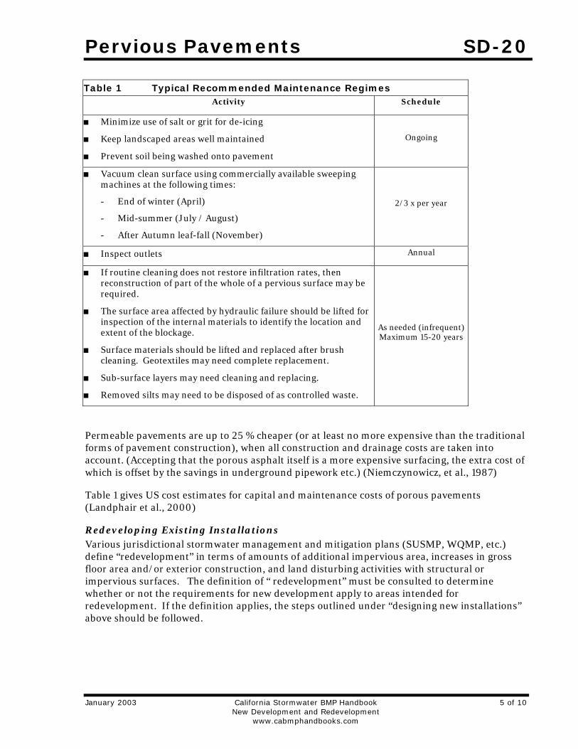
Studies in the UK have shown satisfactory operation of porous pavement systems without maintenance for over 10 years and recent work by Imbe et al. at 9th ICUD, Portland, 2002 describes systems operating for over 20 years without maintenance. However, performance under such regimes could not be guaranteed, Table 1 shows typical recommended maintenance regimes:
Pervious Pavements SD-20
January 2003 California Stormwater BMP Handbook 5 of 10 New Development and Redevelopment www.cabmphandbooks.com
Table 1 Typical Recommended Maintenance Regimes Activity Schedule
Minimize use of salt or grit for de-icing
Keep landscaped areas well maintained
Prevent soil being washed onto pavement
Ongoing
Vacuum clean surface using commercially available sweeping machines at the following times:
- End of winter (April)
- Mid-summer (July / August)
- After Autumn leaf-fall (November)
2/3 x per year
Inspect outlets Annual
If routine cleaning does not restore infiltration rates, then reconstruction of part of the whole of a pervious surface may be required.
The surface area affected by hydraulic failure should be lifted for inspection of the internal materials to identify the location and extent of the blockage.
Surface materials should be lifted and replaced after brush cleaning. Geotextiles may need complete replacement.
Sub-surface layers may need cleaning and replacing.
Removed silts may need to be disposed of as controlled waste.
As needed (infrequent) Maximum 15-20 years
Permeable pavements are up to 25 % cheaper (or at least no more expensive than the traditional forms of pavement construction), when all construction and drainage costs are taken into account. (Accepting that the porous asphalt itself is a more expensive surfacing, the extra cost of which is offset by the savings in underground pipework etc.) (Niemczynowicz, et al., 1987)
Table 1 gives US cost estimates for capital and maintenance costs of porous pavements (Landphair et al., 2000)
Redeveloping Existing Installations Various jurisdictional stormwater management and mitigation plans (SUSMP, WQMP, etc.) define “redevelopment” in terms of amounts of additional impervious area, increases in gross floor area and/or exterior construction, and land disturbing activities with structural or impervious surfaces. The definition of “ redevelopment” must be consulted to determine whether or not the requirements for new development apply to areas intended for redevelopment. If the definition applies, the steps outlined under “designing new installations” above should be followed.
SD-20 Pervious Pavements
6 of 10 California Stormwater BMP Handbook January 2003 New Development and Redevelopment www.cabmphandbooks.com
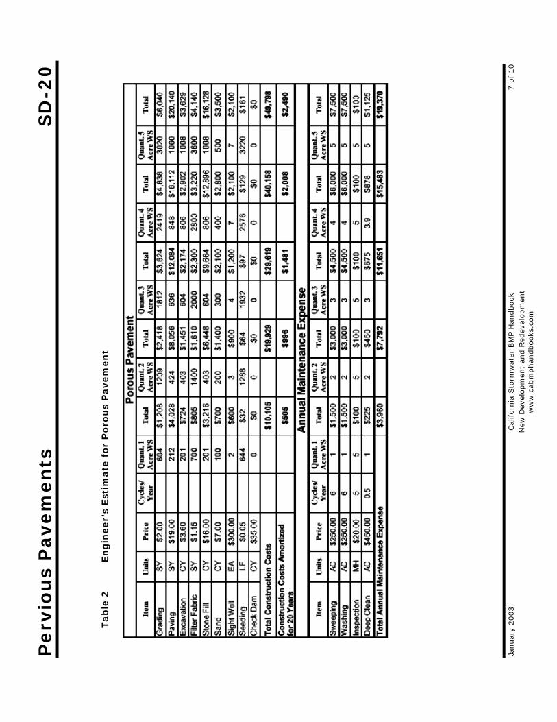
Additional Information Cost Considerations Permeable pavements are up to 25 % cheaper (or at least no more expensive than the traditional forms of pavement construction), when all construction and drainage costs are taken into account. (Accepting that the porous asphalt itself is a more expensive surfacing, the extra cost of which is offset by the savings in underground pipework etc.) (Niemczynowicz, et al., 1987)
Table 2 gives US cost estimates for capital and maintenance costs of porous pavements (Landphair et al., 2000)
Perv
iou
s P
avem
en
ts
SD
-20
Januar
y 2003
Cal
iforn
ia S
torm
wat
er B
MP H
andbook
7 o
f 10
N
ew D
evel
opm
ent
and R
edev
elopm
ent
w
ww
.cab
mphandbooks
.com
Tab
le 2
En
gin
eer’
s Est
imate
fo
r P
oro
us
Pavem
en
t

SD-20 Pervious Pavements
8 of 10 California Stormwater BMP Handbook January 2003 New Development and Redevelopment www.cabmphandbooks.com
Other Resources Abbott C.L. and Comino-Mateos L. 2001. In situ performance monitoring of an infiltration drainage system and field testing of current design procedures. Journal CIWEM, 15(3), pp.198-202.
Construction Industry Research and Information Association (CIRIA). 2002. Source Control using Constructed Pervious Surfaces C582, London, SW1P 3AU.
Construction Industry Research and Information Association (CIRIA). 2000. Sustainable urban drainage systems - design manual for Scotland and Northern Ireland Report C521, London, SW1P 3AU.
Construction Industry Research and Information Association (CIRIA). 2000 C522 Sustainable urban drainage systems - design manual for England and Wales, London, SW1P 3AU.
Construction Industry Research and Information Association (CIRIA). RP448 Manual of good practice for the design, construction and maintenance of infiltration drainage systems for stormwater runoff control and disposal, London, SW1P 3AU.
Dierkes C., Kuhlmann L., Kandasamy J. & Angelis G. Pollution Retention Capability and Maintenance of Permeable Pavements. Proc 9th International Conference on Urban Drainage, Portland Oregon, September 2002.
Hart P (2002) Permeable Paving as a Stormwater Source Control System. Paper presented at Scottish Hydraulics Study Group 14th Annual seminar, SUDS. 22 March 2002, Glasgow.
Kobayashi M., 1999. Stormwater runoff control in Nagoya City. Proc. 8 th Int. Conf. on
Urban Storm Drainage, Sydney, Australia, pp.825-833.
Landphair, H., McFalls, J., Thompson, D., 2000, Design Methods, Selection, and Cost Effectiveness of Stormwater Quality Structures, Texas Transportation Institute Research Report 1837-1, College Station, Texas.
Legret M, Colandini V, Effects of a porous pavement with reservior strucutre on runoff water:water quality and the fate of heavy metals. Laboratoire Central Des Ponts et Chaussesss
Macdonald K. & Jefferies C. Performance Comparison of Porous Paved and Traditional Car Parks. Proc. First National Conference on Sustainable Drainage Systems, Coventry June 2001.
Niemczynowicz J, Hogland W, 1987: Test of porous pavements performed in Lund, Sweden, in Topics in Drainage Hydraulics and Hydrology. BC. Yen (Ed.), pub. Int. Assoc. For Hydraulic Research, pp 19-80.
Pratt C.J. SUSTAINABLE URBAN DRAINAGE – A Review of published material on the performance of various SUDS devices prepared for the UK Environment Agency. Coventry University, UK December 2001.
Pratt C.J., 1995. Infiltration drainage – case studies of UK practice. Project Report
Pervious Pavements SD-20
January 2003 California Stormwater BMP Handbook 9 of 10 New Development and Redevelopment www.cabmphandbooks.com
22,Construction Industry Research and Information Association, London, SW1P 3AU; also known as National Rivers Authority R & D Note 485
Pratt. C. J., 1990. Permeable Pavements for Stormwater Quality Enhancement. In: Urban Stormwater Quality Enhancement - Source Control, retrofitting and combined sewer technology, Ed. H.C. Torno, ASCE, ISBN 087262 7594, pp. 131-155
Raimbault G., 1997 French Developments in Reservoir Structures Sustainable water resources I the 21st century. Malmo Sweden
Schlüter W. & Jefferies C. Monitoring the outflow from a Porous Car Park Proc. First National Conference on Sustainable Drainage Systems, Coventry June 2001.
Wild, T.C., Jefferies, C., and D’Arcy, B.J. SUDS in Scotland – the Scottish SUDS database Report No SR(02)09 Scotland and Northern Ireland Forum for Environmental Research, Edinburgh. In preparation August 2002.
SD-20 Pervious Pavements
10 of 10 California Stormwater BMP Handbook January 2003 New Development and Redevelopment www.cabmphandbooks.com
Schematics of a Pervious Pavement System
Alternative Building Materials SD-21
January 2003 California Stormwater BMP Handbook 1 of 3 New Development and Redevelopment www.cabmphandbook.com
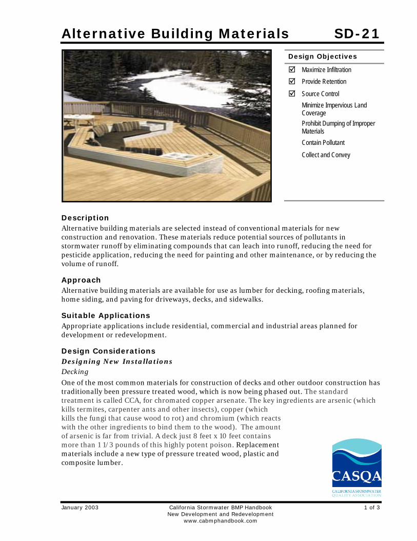
Description Alternative building materials are selected instead of conventional materials for new construction and renovation. These materials reduce potential sources of pollutants in stormwater runoff by eliminating compounds that can leach into runoff, reducing the need for pesticide application, reducing the need for painting and other maintenance, or by reducing the volume of runoff.
Approach Alternative building materials are available for use as lumber for decking, roofing materials, home siding, and paving for driveways, decks, and sidewalks.
Suitable Applications Appropriate applications include residential, commercial and industrial areas planned for development or redevelopment.
Design Considerations Designing New Installations Decking
One of the most common materials for construction of decks and other outdoor construction has traditionally been pressure treated wood, which is now being phased out. The standard treatment is called CCA, for chromated copper arsenate. The key ingredients are arsenic (which kills termites, carpenter ants and other insects), copper (which kills the fungi that cause wood to rot) and chromium (which reacts with the other ingredients to bind them to the wood). The amount of arsenic is far from trivial. A deck just 8 feet x 10 feet contains more than 1 1/3 pounds of this highly potent poison. Replacement materials include a new type of pressure treated wood, plastic and composite lumber.
Design Objectives
Maximize Infiltration
Provide Retention
Source Control
Minimize Impervious Land Coverage
Prohibit Dumping of Improper Materials
Contain Pollutant
Collect and Convey
SD-21 Alternative Building Materials
2 of 3 California Stormwater BMP Handbook January 2003 New Development and Redevelopment www.cabmphandbook.com
There are currently over 20 products in the market consisting of plastic or plastic-wood composites. Plastic lumber is made from 100% recycled plastic, # 2 HDPE and polyethylene plastic milk jugs and soap bottles. Plastic-wood composites are a combination of plastic and wood fibers or sawdust. These materials are a long lasting exterior weather, insect, and chemical resistant wood lumber replacement for non structural applications. Use it for decks, docks, raised garden beds and planter boxes, pallets, hand railings, outdoor furniture, animal pens, boat decks, etc.
New pressure treated wood uses a much safer recipe, ACQ, which stands for ammoniacal copper quartenary. It contains no arsenic and no chromium. Yet the American Wood Preservers Association has found it to be just as effective as the standard formula. ACQ is common in Japan and Europe.
Roofing
Several studies have indicated that metal used as roofing material, flashing, or gutters can leach metals into the environment. The leaching occurs because rainfall is slightly acidic and slowly dissolved the exposed metals. Common traditional applications include copper sheathing and galvanized (zinc) gutters.
Coated metal products are available for both roofing and gutter applications. These products eliminate contact of bare metal with rainfall, eliminating one source of metals in runoff. There are also roofing materials made of recycled rubber and plastic that resemble traditional materials.
A less traditional approach is the use of green roofs. These roofs are not just green, they're alive. Planted with grasses and succulents, low- profile green roofs reduce the urban heat island effect, stormwater runoff, and cooling costs, while providing wildlife habitat and a connection to nature for building occupants. These roofs are widely used on industrial facilities in Europe and have been established as experimental installations in several locations in the US, including Portland, Oregon. Their feasibility is questionable in areas of California with prolonged, dry, hot weather.
Paved Areas
Traditionally, concrete is used for construction of patios, sidewalks, and driveways. Although it is non-toxic, these paved areas reduce stormwater infiltration and increase the volume and rate of runoff. This increase in the amount of runoff is the leading cause of stream channel degradation in urban areas.
There are a number of alternative materials that can be used in these applications, including porous concrete and asphalt, modular blocks, and crushed granite. These materials, especially modular paving blocks, are widely available and a well established method to reduce stormwater runoff.
Building Siding
Wood siding is commonly used on the exterior of residential construction. This material weathers fairly rapidly and requires repeated painting to prevent rotting. Alternative “new” products for this application include cement-fiber and vinyl. Cement-fiber siding is a masonry product made from Portland cement, sand, and cellulose and will not burn, cup, swell, or shrink.
Alternative Building Materials SD-21
January 2003 California Stormwater BMP Handbook 3 of 3 New Development and Redevelopment www.cabmphandbook.com
Pesticide Reduction A common use of powerful pesticides is for the control of termites. Chlordane was used for many years for this purpose and is now found in urban streams and lakes nationwide. There are a number of physical barriers that can be installed during construction to help reduce the use of pesticides.
Sand barriers for subterranean termites are a physical deterrent because the termites cannot tunnel through it. Sand barriers can be applied in crawl spaces under pier and beam foundations, under slab foundations, and between the foundation and concrete porches, terraces, patios and steps. Other possible locations include under fence posts, underground electrical cables, water and gas lines, telephone and electrical poles, inside hollow tile cells and against retaining walls.
Metal termite shields are physical barriers to termites which prevent them from building invisible tunnels. In reality, metal shields function as a helpful termite detection device, forcing them to build tunnels on the outside of the shields which are easily seen. Metal termite shields also help prevent dampness from wicking to adjoining wood members which can result in rot, thus making the material more attractive to termites and other pests. Metal flashing and metal plates can also be used as a barrier between piers and beams of structures such as decks, which are particularly vulnerable to termite attack.
Redeveloping Existing Installations Various jurisdictional stormwater management and mitigation plans (SUSMP, WQMP, etc.) define “redevelopment” in terms of amounts of additional impervious area, increases in gross floor area and/or exterior construction, and land disturbing activities with structural or impervious surfaces. The definition of “redevelopment” must be consulted to determine whether or not the requirements for new development apply to areas intended for redevelopment. If the definition applies, the steps outlined under “designing new installations” above should be followed.
Other Resources There are no good, independent, comprehensive sources of information on alternative building materials for use in minimizing the impacts of stormwater runoff. Most websites or other references to “green” or “alternative” building materials focus on indoor applications, such as formaldehyde free plywood and low VOC paints, carpets, and pads. Some supplemental information on alternative materials is available from the manufacturers.
Fires are a source of concern in many areas of California. Information on the flammability of alternative decking materials is available from the University of California Forest Product Laboratory (UCFPL) website at: http://www.ucfpl.ucop.edu/WDDeckIntro.htm

Fueling Areas SD-30
January 2003 California Stormwater BMP Handbook 1 of 3 New Development and Redevelopment www.cabmphandbooks.com
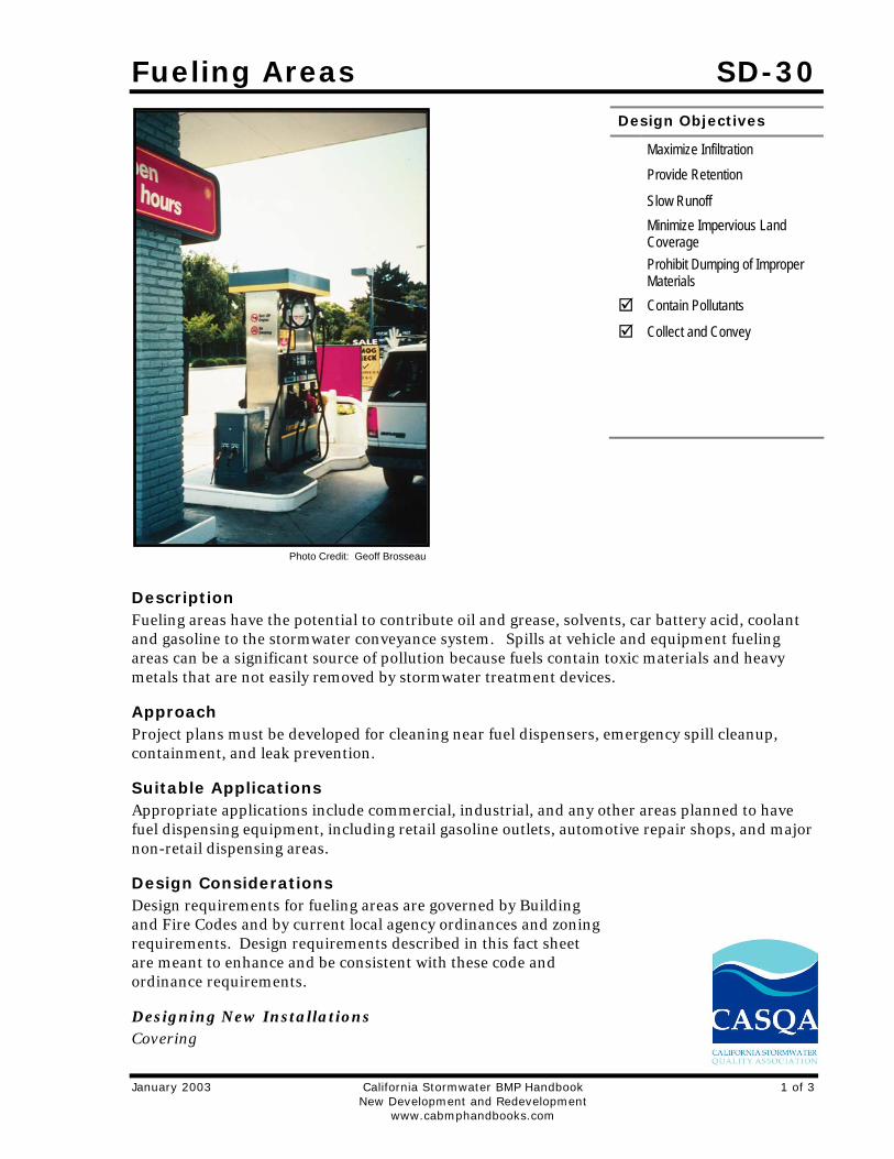
Description Fueling areas have the potential to contribute oil and grease, solvents, car battery acid, coolant and gasoline to the stormwater conveyance system. Spills at vehicle and equipment fueling areas can be a significant source of pollution because fuels contain toxic materials and heavy metals that are not easily removed by stormwater treatment devices.
Approach Project plans must be developed for cleaning near fuel dispensers, emergency spill cleanup, containment, and leak prevention.
Suitable Applications Appropriate applications include commercial, industrial, and any other areas planned to have fuel dispensing equipment, including retail gasoline outlets, automotive repair shops, and major non-retail dispensing areas.
Design Considerations Design requirements for fueling areas are governed by Building and Fire Codes and by current local agency ordinances and zoning requirements. Design requirements described in this fact sheet are meant to enhance and be consistent with these code and ordinance requirements.
Designing New Installations Covering
Design Objectives
Maximize Infiltration
Provide Retention
Slow Runoff
Minimize Impervious Land Coverage
Prohibit Dumping of Improper Materials
Contain Pollutants
Collect and Convey
Photo Credit: Geoff Brosseau
SD-30 Fueling Areas
2 of 3 California Stormwater BMP Handbook January 2003 New Development and Redevelopment www.cabmphandbooks.com
Fuel dispensing areas should provide an overhanging roof structure or canopy. The cover’s minimum dimensions must be equal to or greater than the area within the grade break. The cover must not drain onto the fuel dispensing area and the downspouts must be routed to prevent drainage across the fueling area. The fueling area should drain to the project’s treatment control BMP(s) prior to discharging to the stormwater conveyance system. Note - If fueling large equipment or vehicles that would prohibit the use of covers or roofs, the fueling island should be designed to sufficiently accommodate the larger vehicles and equipment and to prevent stormwater run-on and runoff. Grade to direct stormwater to a dead-end sump.
Surfacing
Fuel dispensing areas should be paved with Portland cement concrete (or equivalent smooth impervious surface). The use of asphalt concrete should be prohibited. Use asphalt sealant to protect asphalt paved areas surrounding the fueling area. This provision may be made to sites that have pre-existing asphalt surfaces.
The concrete fuel dispensing area should be extended a minimum of 6.5 ft from the corner of each fuel dispenser, or the length at which the hose and nozzle assembly may be operated plus 1 ft, whichever is less.
Grading/Contouring
Dispensing areas should have an appropriate slope to prevent ponding, and be separated from the rest of the site by a grade break that prevents run-on of urban runoff. (Slope is required to be 2 to 4% in some jurisdictions’ stormwater management and mitigation plans.)
Fueling areas should be graded to drain toward a dead-end sump. Runoff from downspouts/roofs should be directed away from fueling areas. Do not locate storm drains in the immediate vicinity of the fueling area.
Redeveloping Existing Installations Various jurisdictional stormwater management and mitigation plans (SUSMP, WQMP, etc.) define “redevelopment” in terms of amounts of additional impervious area, increases in gross floor area and/or exterior construction, and land disturbing activities with structural or impervious surfaces. The definition of “ redevelopment” must be consulted to determine whether or not the requirements for new development apply to areas intended for redevelopment. If the definition applies, the steps outlined under “designing new installations” above should be followed.
Additional Information In the case of an emergency, provide storm drain seals, such as isolation valves, drain plugs,
or drain covers, to prevent spills or contaminated stormwater from entering the stormwater conveyance system.
Other Resources A Manual for the Standard Urban Stormwater Mitigation Plan (SUSMP), Los Angeles County Department of Public Works, May 2002.
Model Standard Urban Storm Water Mitigation Plan (SUSMP) for San Diego County, Port of San Diego, and Cities in San Diego County, February 14, 2002.
Fueling Areas SD-30
January 2003 California Stormwater BMP Handbook 3 of 3 New Development and Redevelopment www.cabmphandbooks.com
Model Water Quality Management Plan (WQMP) for County of Orange, Orange County Flood Control District, and the Incorporated Cities of Orange County, Draft February 2003.
Ventura Countywide Technical Guidance Manual for Stormwater Quality Control Measures, July 2002.


Maintenance Bays & Docks SD-31
January 2003 California Stormwater BMP Handbook 1 of 2 New Development and Redevelopment www.cabmphandbooks.com
Description Several measures can be taken to prevent operations at maintenance bays and loading docks from contributing a variety of toxic compounds, oil and grease, heavy metals, nutrients, suspended solids, and other pollutants to the stormwater conveyance system.
Approach In designs for maintenance bays and loading docks, containment is encouraged. Preventative measures include overflow containment structures and dead-end sumps. However, in the case of loading docks from grocery stores and warehouse/distribution centers, engineered infiltration systems may be considered.
Suitable Applications Appropriate applications include commercial and industrial areas planned for development or redevelopment.
Design Considerations Design requirements for vehicle maintenance and repair are governed by Building and Fire Codes, and by current local agency ordinances, and zoning requirements. The design criteria described in this fact sheet are meant to enhance and be consistent with these code requirements.
Designing New Installations Designs of maintenance bays should consider the following:
Repair/maintenance bays and vehicle parts with fluids should be indoors; or designed to preclude urban run-on and runoff.
Repair/maintenance floor areas should be paved with Portland cement concrete (or equivalent smooth impervious surface).
Design Objectives
Maximize Infiltration
Provide Retention
Slow Runoff
Minimize Impervious Land Coverage
Prohibit Dumping of Improper Materials
Contain Pollutants
Collect and Convey
SD-31 Maintenance Bays & Docks
2 of 2 California Stormwater BMP Handbook January 2003 New Development and Redevelopment www.cabmphandbooks.com
Repair/maintenance bays should be designed to capture all wash water leaks and spills. Provide impermeable berms, drop inlets, trench catch basins, or overflow containment structures around repair bays to prevent spilled materials and wash-down waters form entering the storm drain system. Connect drains to a sump for collection and disposal. Direct connection of the repair/maintenance bays to the storm drain system is prohibited. If required by local jurisdiction, obtain an Industrial Waste Discharge Permit.
Other features may be comparable and equally effective.
The following designs of loading/unloading dock areas should be considered:
Loading dock areas should be covered, or drainage should be designed to preclude urban run-on and runoff.
Direct connections into storm drains from depressed loading docks (truck wells) are prohibited.
Below-grade loading docks from grocery stores and warehouse/distribution centers of fresh food items should drain through water quality inlets, or to an engineered infiltration system, or an equally effective alternative. Pre-treatment may also be required.
Other features may be comparable and equally effective.
Redeveloping Existing Installations Various jurisdictional stormwater management and mitigation plans (SUSMP, WQMP, etc.) define “redevelopment” in terms of amounts of additional impervious area, increases in gross floor area and/or exterior construction, and land disturbing activities with structural or impervious surfaces. The definition of “ redevelopment” must be consulted to determine whether or not the requirements for new development apply to areas intended for redevelopment. If the definition applies, the steps outlined under “designing new installations” above should be followed.
Additional Information Stormwater and non-stormwater will accumulate in containment areas and sumps with impervious surfaces. Contaminated accumulated water must be disposed of in accordance with applicable laws and cannot be discharged directly to the storm drain or sanitary sewer system without the appropriate permit.
Other Resources A Manual for the Standard Urban Stormwater Mitigation Plan (SUSMP), Los Angeles County Department of Public Works, May 2002.
Model Standard Urban Storm Water Mitigation Plan (SUSMP) for San Diego County, Port of San Diego, and Cities in San Diego County, February 14, 2002.
Model Water Quality Management Plan (WQMP) for County of Orange, Orange County Flood Control District, and the Incorporated Cities of Orange County, Draft February 2003.
Ventura Countywide Technical Guidance Manual for Stormwater Quality Control Measures, July 2002.
Trash Storage Areas SD-32
January 2003 California Stormwater BMP Handbook 1 of 2 New Development and Redevelopment www.cabmphandbooks.com
Description Trash storage areas are areas where a trash receptacle (s) are located for use as a repository for solid wastes. Stormwater runoff from areas where trash is stored or disposed of can be polluted. In addition, loose trash and debris can be easily transported by water or wind into nearby storm drain inlets, channels, and/or creeks. Waste handling operations that may be sources of stormwater pollution include dumpsters, litter control, and waste piles.
Approach This fact sheet contains details on the specific measures required to prevent or reduce pollutants in stormwater runoff associated with trash storage and handling. Preventative measures including enclosures, containment structures, and impervious pavements to mitigate spills, should be used to reduce the likelihood of contamination.
Suitable Applications Appropriate applications include residential, commercial and industrial areas planned for development or redevelopment. (Detached residential single-family homes are typically excluded from this requirement.)
Design Considerations Design requirements for waste handling areas are governed by Building and Fire Codes, and by current local agency ordinances and zoning requirements. The design criteria described in this fact sheet are meant to enhance and be consistent with these code and ordinance requirements. Hazardous waste should be handled in accordance with legal requirements established in Title 22, California Code of Regulation.
Wastes from commercial and industrial sites are typically hauled by either public or commercial carriers that may have design or access requirements for waste storage areas. The design criteria in this fact sheet are recommendations and are not intended to be in conflict with requirements established by the waste hauler. The waste hauler should be contacted prior to the design of your site trash collection areas. Conflicts or issues should be discussed with the local agency.
Designing New Installations Trash storage areas should be designed to consider the following structural or treatment control BMPs:
Design trash container areas so that drainage from adjoining roofs and pavement is diverted around the area(s) to avoid run-on. This might include berming or grading the waste handling area to prevent run-on of stormwater.
Make sure trash container areas are screened or walled to prevent off-site transport of trash.
Design Objectives
Maximize Infiltration
Provide Retention
Slow Runoff
Minimize Impervious Land Coverage
Prohibit Dumping of Improper Materials
Contain Pollutants
Collect and Convey
SD-32 Trash Storage Areas
2 of 2 California Stormwater BMP Handbook January 2003 New Development and Redevelopment www.cabmphandbooks.com
Use lined bins or dumpsters to reduce leaking of liquid waste.
Provide roofs, awnings, or attached lids on all trash containers to minimize direct precipitation and prevent rainfall from entering containers.
Pave trash storage areas with an impervious surface to mitigate spills.
Do not locate storm drains in immediate vicinity of the trash storage area.
Post signs on all dumpsters informing users that hazardous materials are not to be disposed of therein.
Redeveloping Existing Installations Various jurisdictional stormwater management and mitigation plans (SUSMP, WQMP, etc.) define “redevelopment” in terms of amounts of additional impervious area, increases in gross floor area and/or exterior construction, and land disturbing activities with structural or impervious surfaces. The definition of “ redevelopment” must be consulted to determine whether or not the requirements for new development apply to areas intended for redevelopment. If the definition applies, the steps outlined under “designing new installations” above should be followed.
Additional Information Maintenance Considerations The integrity of structural elements that are subject to damage (i.e., screens, covers, and signs) must be maintained by the owner/operator. Maintenance agreements between the local agency and the owner/operator may be required. Some agencies will require maintenance deed restrictions to be recorded of the property title. If required by the local agency, maintenance agreements or deed restrictions must be executed by the owner/operator before improvement plans are approved.
Other Resources A Manual for the Standard Urban Stormwater Mitigation Plan (SUSMP), Los Angeles County Department of Public Works, May 2002.
Model Standard Urban Storm Water Mitigation Plan (SUSMP) for San Diego County, Port of San Diego, and Cities in San Diego County, February 14, 2002.
Model Water Quality Management Plan (WQMP) for County of Orange, Orange County Flood Control District, and the Incorporated Cities of Orange County, Draft February 2003.
Ventura Countywide Technical Guidance Manual for Stormwater Quality Control Measures, July 2002.
Vehicle Washing Areas SD-33
January 2003 California Stormwater BMP Handbook 1 of 2 New Development and Redevelopment www.cabmphandbooks.com
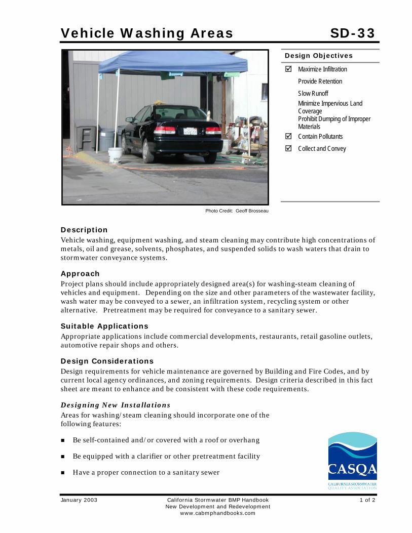
Description Vehicle washing, equipment washing, and steam cleaning may contribute high concentrations of metals, oil and grease, solvents, phosphates, and suspended solids to wash waters that drain to stormwater conveyance systems.
Approach Project plans should include appropriately designed area(s) for washing-steam cleaning of vehicles and equipment. Depending on the size and other parameters of the wastewater facility, wash water may be conveyed to a sewer, an infiltration system, recycling system or other alternative. Pretreatment may be required for conveyance to a sanitary sewer.
Suitable Applications Appropriate applications include commercial developments, restaurants, retail gasoline outlets, automotive repair shops and others.
Design Considerations Design requirements for vehicle maintenance are governed by Building and Fire Codes, and by current local agency ordinances, and zoning requirements. Design criteria described in this fact sheet are meant to enhance and be consistent with these code requirements.
Designing New Installations Areas for washing/steam cleaning should incorporate one of the following features:
Be self-contained and/or covered with a roof or overhang
Be equipped with a clarifier or other pretreatment facility
Have a proper connection to a sanitary sewer
Design Objectives
Maximize Infiltration
Provide Retention
Slow Runoff
Minimize Impervious Land Coverage
Prohibit Dumping of Improper Materials
Contain Pollutants
Collect and Convey
Photo Credit: Geoff Brosseau
SD-33 Vehicle Washing Areas
2 of 2 California Stormwater BMP Handbook January 2003 New Development and Redevelopment www.cabmphandbooks.com
Include other features which are comparable and equally effective
CAR WASH AREAS - Some jurisdictions’ stormwater management plans include vehicle-cleaning area source control design requirements for community car wash racks in complexes with a large number of dwelling units. In these cases, wash water from the areas may be directed to the sanitary sewer, to an engineered infiltration system, or to an equally effective alternative. Pre-treatment may also be required.
Depending on the jurisdiction, developers may be directed to divert surface water runoff away from the exposed area around the wash pad ( parking lot, storage areas), and wash pad itself to alternatives other than the sanitary sewer. Roofing may be required for exposed wash pads.
It is generally advisable to cover areas used for regular washing of vehicles, trucks, or equipment, surround them with a perimeter berm, and clearly mark them as a designated washing area. Sumps or drain lines can be installed to collect wash water, which may be treated for reuse or recycling, or for discharge to the sanitary sewer. Jurisdictions may require some form of pretreatment, such as a trap, for these areas.
Redeveloping Existing Installations Various jurisdictional stormwater management and mitigation plans (SUSMP, WQMP, etc.) define “redevelopment” in terms of amounts of additional impervious area, increases in gross floor area and/or exterior construction, and land disturbing activities with structural or impervious surfaces. The definition of “ redevelopment” must be consulted to determine whether or not the requirements for new development apply to areas intended for redevelopment.
Additional Information Maintenance Considerations Stormwater and non-stormwater will accumulate in containment areas and sumps with impervious surfaces. Contaminated accumulated water must be disposed of in accordance with applicable laws and cannot be discharged directly to the storm drain or sanitary sewer system without the appropriate permit.
Other Resources A Manual for the Standard Urban Stormwater Mitigation Plan (SUSMP), Los Angeles County Department of Public Works, May 2002.
Model Standard Urban Storm Water Mitigation Plan (SUSMP) for San Diego County, Port of San Diego, and Cities in San Diego County, February 14, 2002.
Model Water Quality Management Plan (WQMP) for County of Orange, Orange County Flood Control District, and the Incorporated Cities of Orange County, Draft February 2003.
Ventura Countywide Technical Guidance Manual for Stormwater Quality Control Measures, July 2002.

Outdoor Material Storage Areas SD-34
January 2003 California Stormwater BMP Handbook 1 of 3 New Development and Redevelopment www.cabmphandbooks.com
Description Proper design of outdoor storage areas for materials reduces opportunity for toxic compounds, oil and grease, heavy metals, nutrients, suspended solids, and other pollutants to enter the stormwater conveyance system. Materials may be in the form of raw products, by-products, finished products, and waste products. The type of pollutants associated with the materials will vary depending on the type of commercial or industrial activity.
Approach Outdoor storage areas require a drainage approach different from the typical infiltration/detention strategy. In outdoor storage areas, infiltration is discouraged. Containment is encouraged. Preventative measures include enclosures, secondary containment structures and impervious surfaces.
Suitable Applications Appropriate applications include residential, commercial and industrial areas planned for development or redevelopment.
Design Considerations Some materials are more of a concern than others. Toxic and hazardous materials must be prevented from coming in contact with stormwater. Non-toxic or non-hazardous materials do not have to be prevented from stormwater contact. However, these materials may have toxic effects on receiving waters if allowed to be discharged with stormwater in significant quantities. Accumulated material on an impervious surface could result in significant impact on the rivers or streams that receive the runoff.
Material may be stored in a variety of ways, including bulk piles, containers, shelving, stacking, and tanks. Stormwater contamination may be prevented by eliminating the possibility of stormwater contact with the material storage areas either through diversion, cover, or capture of the stormwater. Control measures may also include minimizing the storage area. Design
Design Objectives
Maximize Infiltration
Provide Retention
Slow Runoff
Minimize Impervious Land Coverage
Prohibit Dumping of Improper Materials
Contain Pollutant
Collect and Convey
SD-34 Outdoor Material Storage Areas
2 of 3 California Stormwater BMP Handbook January 2003 New Development and Redevelopment www.cabmphandbooks.com
requirements for material storage areas are governed by Building and Fire Codes, and by current City or County ordinances and zoning requirements. Control measures are site specific, and must meet local agency requirements.
Designing New Installations Where proposed project plans include outdoor areas for storage of materials that may contribute pollutants to the stormwater conveyance system, the following structural or treatment BMPS should be considered:
Materials with the potential to contaminate stormwater should be: (1) placed in an enclosure such as, but not limited to, a cabinet, shed, or similar structure that prevents contact with runoff or spillage to the stormwater conveyance system, or (2) protected by secondary containment structures such as berms, dikes, or curbs.
The storage area should be paved and sufficiently impervious to contain leaks and spills.
The storage area should slope towards a dead-end sump to contain spills and direct runoff from downspouts/roofs should be directed away from storage areas.
The storage area should have a roof or awning that extends beyond the storage area to minimize collection of stormwater within the secondary containment area. A manufactured storage shed may be used for small containers.
Note that the location(s) of installations of where these preventative measures will be employed must be included on the map or plans identifying BMPs.
Redeveloping Existing Installations Various jurisdictional stormwater management and mitigation plans (SUSMP, WQMP, etc.) define “redevelopment” in terms of amounts of additional impervious area, increases in gross floor area and/or exterior construction, and land disturbing activities with structural or impervious surfaces. The definition of “ redevelopment” must be consulted to determine whether or not the requirements for new development apply to areas intended for redevelopment. If the definition applies, the steps outlined under “designing new installations” above should be followed.
Additional Information Stormwater and non-stormwater will accumulate in containment areas and sumps with impervious surfaces. Contaminated accumulated water must be disposed of in accordance with applicable laws and cannot be discharged directly to the storm drain or sanitary sewer system without the appropriate permits.
Other Resources A Manual for the Standard Urban Stormwater Mitigation Plan (SUSMP), Los Angeles County Department of Public Works, May 2002.
Model Standard Urban Storm Water Mitigation Plan (SUSMP) for San Diego County, Port of San Diego, and Cities in San Diego County, February 14, 2002.
Outdoor Material Storage Areas SD-34
January 2003 California Stormwater BMP Handbook 3 of 3 New Development and Redevelopment www.cabmphandbooks.com
Model Water Quality Management Plan (WQMP) for County of Orange, Orange County Flood Control District, and the Incorporated Cities of Orange County, Draft February 2003.
Ventura Countywide Technical Guidance Manual for Stormwater Quality Control Measures, July 2002.

Outdoor Work Areas SD-35
January 2003 California Stormwater BMP Handbook 1 of 2 New Development and Redevelopment www.cabmphandbooks.com
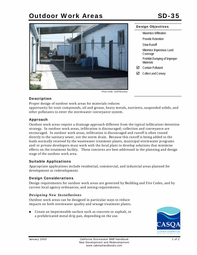
Description Proper design of outdoor work areas for materials reduces opportunity for toxic compounds, oil and grease, heavy metals, nutrients, suspended solids, and other pollutants to enter the stormwater conveyance system.
Approach Outdoor work areas require a drainage approach different from the typical infiltration/detention strategy. In outdoor work areas, infiltration is discouraged; collection and conveyance are encouraged. In outdoor work areas, infiltration is discouraged and runoff is often routed directly to the sanitary sewer, not the storm drain. Because this runoff is being added to the loads normally received by the wastewater treatment plants, municipal stormwater programs and/or private developers must work with the local plant to develop solutions that minimize effects on the treatment facility. These concerns are best addressed in the planning and design stage of the outdoor work area.
Suitable Applications Appropriate applications include residential, commercial, and industrial areas planned for development or redevelopment.
Design Considerations Design requirements for outdoor work areas are governed by Building and Fire Codes, and by current local agency ordinances, and zoning requirements.
Designing New Installations Outdoor work areas can be designed in particular ways to reduce impacts on both stormwater quality and sewage treatment plants.
Create an impermeable surface such as concrete or asphalt, or a prefabricated metal drip pan, depending on the use.
Design Objectives
Maximize Infiltration
Provide Retention
Slow Runoff
Minimize Impervious Land Coverage
Prohibit Dumping of Improper Materials
Contain Pollutant
Collect and Convey
Photo Credit: Geoff Brosseau
SD-35 Outdoor Work Areas
2 of 2 California Stormwater BMP Handbook January 2003 New Development and Redevelopment www.cabmphandbooks.com
Cover the area with a roof. This prevents rain from falling on the work area and becoming polluted runoff.
Berm or perform mounding around the perimeter of the area to prevent water from adjacent areas from flowing on to the surface of the work area.
Directly connect runoff. Unlike other areas, runoff from work areas is directly connected to the sanitary sewer or other specialized containment system(s). This allows the more highly concentrated pollutants from these areas to receive special treatment that removes particular constituents. Approval for this connection must be obtained from the appropriate sanitary sewer agency.
Locate the work area away from storm drains or catch basins.
Redeveloping Existing Installations Various jurisdictional stormwater management and mitigation plans (SUSMP, WQMP, etc.) define “redevelopment” in terms of amounts of additional impervious area, increases in gross floor area and/or exterior construction, and land disturbing activities with structural or impervious surfaces. The definition of “ redevelopment” must be consulted to determine whether or not the requirements for new development apply to areas intended for redevelopment. If the definition applies, the steps outlined under “designing new installations” above should be followed.
Other Resources A Manual for the Standard Urban Stormwater Mitigation Plan (SUSMP), Los Angeles County Department of Public Works, May 2002.
Model Standard Urban Storm Water Mitigation Plan (SUSMP) for San Diego County, Port of San Diego, and Cities in San Diego County, February 14, 2002.
Model Water Quality Management Plan (WQMP) for County of Orange, Orange County Flood Control District, and the Incorporated Cities of Orange County, Draft February 2003.
Ventura Countywide Technical Guidance Manual for Stormwater Quality Control Measures, July 2002.
Outdoor Processing Areas SD-36
January 2003 California Stormwater BMP Handbook 1 of 2 New Development and Redevelopment www.cabmphandbooks.com
Description Outdoor process equipment operations such as rock grinding or crushing, painting or coating, grinding or sanding, degreasing or parts cleaning, landfills, waste piles, wastewater and solid waste treatment and disposal, and others operations may contribute a variety of toxic compounds, oil and grease, heavy metals, nutrients, suspended solids, and other pollutants to the storm conveyance system.
Approach Outdoor processing areas require a drainage approach different from the typical infiltration/detention strategy. In outdoor process equipment areas, infiltration is discouraged. Containment is encouraged, accompanied by collection and conveyance. Preventative measures include enclosures, secondary containment structures, dead-end sumps, and conveyance to treatment facilities in accordance with conditions established by the applicable sewer agency.
Suitable Applications Appropriate applications include commercial and industrial areas planned for development or redevelopment.
Design Considerations Design requirements for outdoor processing areas are governed by Building and Fire codes, and by current local agency ordinances, and zoning requirements.
Designing New Installations Operations determined to be a potential threat to water quality should consider to the following recommendations:
Cover or enclose areas that would be the most significant source of pollutants; or slope the area toward a dead-end sump; or, discharge to the sanitary sewer system following appropriate treatment in accordance with conditions established by the applicable sewer agency.
Grade or berm area to prevent run-on from surrounding areas.
Do not install storm drains in areas of equipment repair.
Consider other features that are comparable or equally effective.
Provide secondary containment structures (not double wall containers) where wet material processing occurs (e.g., electroplating), to hold spills resulting from accidents, leaking tanks, or equipment, or any other unplanned releases (Note:
Design Objectives
Maximize Infiltration
Provide Retention
Slow Runoff
Minimize Impervious Land Coverage
Prohibit Dumping of Improper Materials
Contain Pollutants
Collect and Convey
SD-36 Outdoor Processing Areas
2 of 2 California Stormwater BMP Handbook January 2003 New Development and Redevelopment www.cabmphandbooks.com
if these are plumbed to the sanitary sewer, they must be with the prior approval of the sewering agency.)
Redeveloping Existing Installations Various jurisdictional stormwater management and mitigation plans (SUSMP, WQMP, etc.) define “redevelopment” in terms of amounts of additional impervious area, increases in gross floor area and/or exterior construction, and land disturbing activities with structural or impervious surfaces. The definition of “ redevelopment” must be consulted to determine whether or not the requirements for new development apply to areas intended for redevelopment. If the definition applies, the steps outlined under “designing new installations” above should be followed.
Additional Information Stormwater and non-stormwater will accumulate in containment areas and sumps with impervious surfaces. Contaminated accumulated water must be disposed of in accordance with applicable laws and cannot be discharged directly to the storm drain or sanitary sewer system without the appropriate permit.
Other Resources A Manual for the Standard Urban Stormwater Mitigation Plan (SUSMP), Los Angeles County Department of Public Works, May 2002.
Model Standard Urban Storm Water Mitigation Plan (SUSMP) for San Diego County, Port of San Diego, and Cities in San Diego County, February 14, 2002.
Model Water Quality Management Plan (WQMP) for County of Orange, Orange County Flood Control District, and the Incorporated Cities of Orange County, Draft February 2003.
Ventura Countywide Technical Guidance Manual for Stormwater Quality Control Measures, July 2002.