Embed Size (px)
Citation preview
Miami-Dade County Public Works Department Traffic Signals & Signs Division
SECTION A653 - Pedestrian Signal Assemblies
Technical Specifications
for
LED PEDESTRIAN SIGNAL MODULES 16-INCH x 18-INCH HAND/PERSON/COUNTDOWN
Esther Calas, P.E. Director
Public Works Department
Robert Williams, P.E., PTOE Chief
Traffic Signals & Signs Division
Prepared by:
Robert Janosi Traffic Control Standards & Specifications Coordinator
JUNE 2011
SECTION A653 - Pedestrian Signal Assemblies LED PEDESTRIAN SIGNAL MODULES
16-INCH x 18-INCH HAND/PERSON/COUNTDOWN
- 2 -
Miami-Dade County specification for LED Pedestrian Signal Modules 16-inch x 18-inch Hand/Person/Countdown meet or exceed the ITE Pedestrian Traffic Control Signal Indicators - Light Emitting Diode Signal Modules (PTCSI LED) dated August 04, 2010; the Florida Department of Transportation's Minimum Specifications for Traffic Control Signals and Devices (MSTCSD), used for the evaluation and certification/approval for listing on the FDOT Approved Product List (APL), and establishes the minimum standards required on MDPW Qualified Product List (QPL) for use in Miami-Dade County, FL.
A653-1 Description Pedestrian Signal Assemblies listed under Section 653 by the Florida Department of Transportation (FDOT) includes pedestrian signal modules, housings, visors, and assembly hardware. A Pedestrian Signal Head is comprised of a signal module installed in housing complete with visor, of which this specification shall provide the minimum performance requirements for a 16-inch x 18-inch LED pedestrian signal module with a countdown timer (hereafter called module) with “Walking Person” (Person), “Upraised Hand” (Hand), and “Countdown Display” (Countdown) icons.
A653-2 General Requirements This specification refers to definitions and practices described in the ITE Pedestrian Traffic Control Signal Indicators - Light Emitting Diode Signal Modules (PTCSI LED) dated August 04, 2010; the 2009 Edition of the Manual of Uniform Traffic Control Devices (MUTCD) and contain additional requirements to ensure optimum long term reliability and performance.
Modules supplied to this specification must comply to the latest version of the ITE PTCSI LED signal module specification; FDOT Minimum Specifications for Traffic Control Signals and Devices (MSTCSD) ), used for the evaluation and certification/approval for listing on the FDOT Approved Product List (APL), and establishes the minimum standards required by Miami-Dade County Public Works Department Traffic Signals and Signs Division (MDPW TSS) on the MDPW Qualified Product List (QPL) for use in Miami-Dade County, FL.
A653-2.1 Manufacturers Requirements and Approvals
A653-2.1.1 Manufacturers supplying modules to this specification shall be a registered participant and have the part numbers being provided to MDPW listed on the Intertek-ETL LED Traffic Signal Modules Certification Program approved modules website with ETL “Verified” Product labeling. Modules shall be qualified for full compliance to the ITE PTCSI LED standard listed in Article A653-2 above, with no exceptions.
A653-2.1.2 Manufacturers supplying modules to this specification shall be registered and approved with FDOT and exact part number(s) shall be listed on the FDOT APL.
SECTION A653 - Pedestrian Signal Assemblies LED PEDESTRIAN SIGNAL MODULES
16-INCH x 18-INCH HAND/PERSON/COUNTDOWN
- 3 -
A653-2.1 Manufacturers Requirements and Approvals (Continued)
A653-2.1.3 Complete lab reports from ETL Intertek shall be submitted to MDPW to confirm Manufacturers part number for requested module type fully meets the ITE PTCSI specification stated in Article A653-2 above and Manufacturer shall provide proof that said part number is listed on the ETL Certification Program “Verified” Product website.
A653-2.1.4 Manufacturer shall submit samples of LED modules to MDPW for evaluation. The County reserves the right to accept or reject the submittal based on incomplete or inaccurate documentation and/or physical appearance of module per this specification.
A653-2.1.5 All documents submitted to MDPW shall be submitted in a well organized binder, tabbed, indexed and with a table of contents. In addition an electronic submission of the binder stated above shall be submitted on a Compact Disc (CD) or Memory Stick, at time of MDPW TSS QPL submission.
A653-2.2 Physical and Mechanical Requirements
A653-2.2.1
The lens shall have a textured outer surface to reduce glare.
A653-2.2.2 Hand/Person/Countdown Display icons that are not illuminated shall NOT be readily visible to the pedestrian at the far end of the crosswalk that the pedestrian signal head indication controls.
A653-2.2.3 All icons and numbers shall have a uniform incandescent, non-pixilated appearance.
A653-2.2.4 All LED’s utilized to illuminate the Hand/Person/Countdown Display icons shall be manufactured utilizing materials that have industry acceptance as being suitable for uses in outdoor applications.
A653-2.2.5 Countdown signal shall display the time remaining in seconds, beginning with the start of the pedestrian clearance interval and ending at the end of the pedestrian clearance interval. Countdown Displays shall not be used during the “Walk” interval. Upon termination of the countdown sequence the countdown shall remain blank until the beginning of the next pedestrian change interval.
SECTION A653 - Pedestrian Signal Assemblies LED PEDESTRIAN SIGNAL MODULES
16-INCH x 18-INCH HAND/PERSON/COUNTDOWN
- 4 -
A653-2.2 Physical and Mechanical Requirements (Continued)
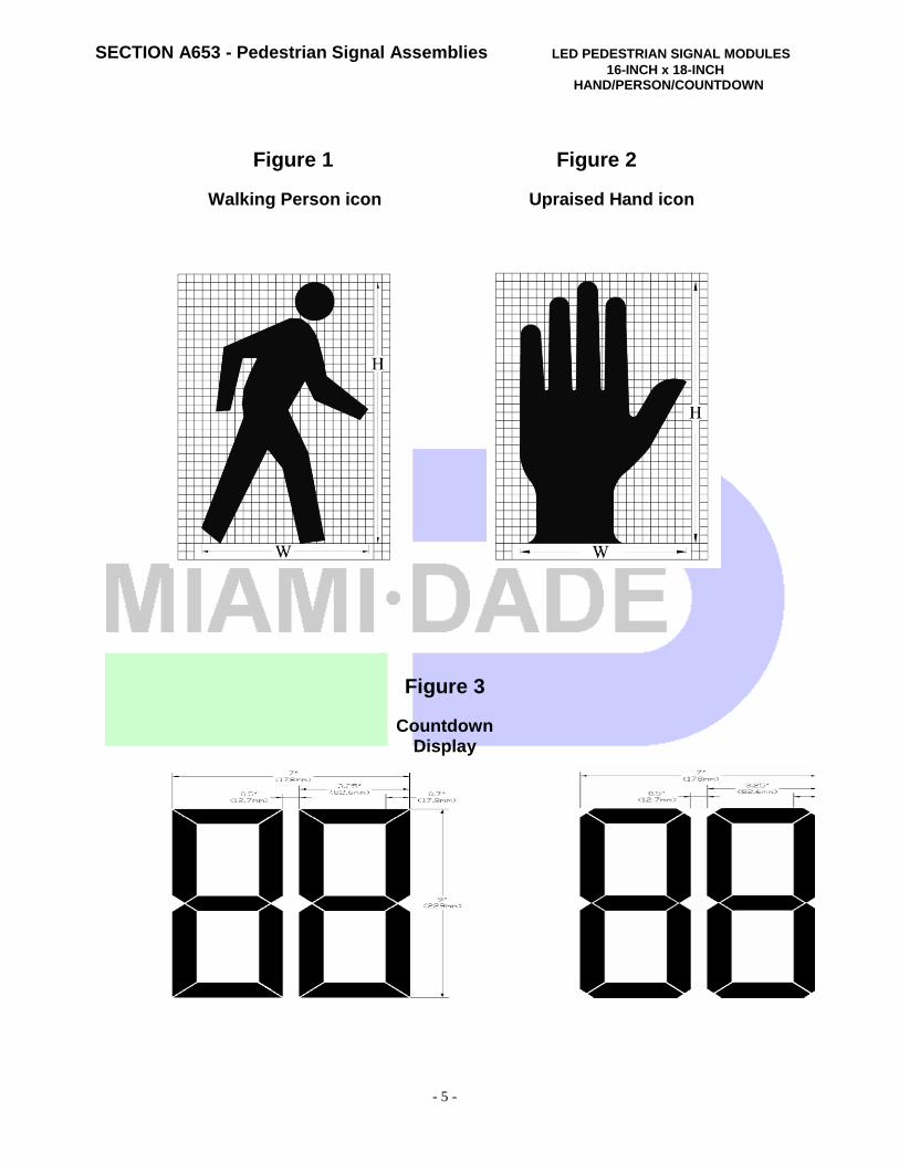
A653-2.2.6 The countdown shall be capable of counting down from 99 to 0. There shall be no leading zeros (0) for numbers less than 10. The display of the “1” digit in the tens position shall be in the right hand portion of the digit.
A653-2.2.7 The configurations of the “Walking Person” icon, “Upraised Hand” icon and “Countdown Display” are illustrated in Figure 1, Figure 2, and Figure 3 respectively on the following page.
A653-2.2.8 Installation of LED modules into existing pedestrian signal housings, with modular neon assemblies, shall only require the removal of the existing module; shall be weather tight and fit securely in the housing; and shall connect directly to existing electrical wiring. Installation shall not require special tools.
[Intentionally Left Blank]
SECTION A653 - Pedestrian Signal Assemblies LED PEDESTRIAN SIGNAL MODULES
16-INCH x 18-INCH HAND/PERSON/COUNTDOWN
- 5 -
Figure 1 Figure 2
Walking Person icon Upraised Hand icon
Figure 3
Countdown Display
SECTION A653 - Pedestrian Signal Assemblies LED PEDESTRIAN SIGNAL MODULES
16-INCH x 18-INCH HAND/PERSON/COUNTDOWN
- 6 -
A653-2.3 Module Identification
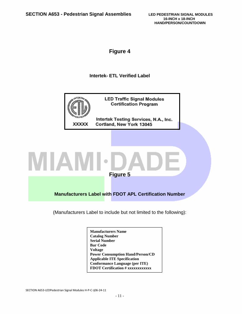
A653-2.3.1 In addition to the labeling requirements of the ITE standard, all modules shall be labeled with the ETL Verified label shown in Figure 4. This label designates the compliance and listing with the Intertek-ETL Traffic Signal Certification Program. A653-2.3.2 Modules shall additionally have a Manufacturer label stating that the unit is in full compliance with applicable ITE specification and shall clearly show the assigned FDOT APL certification number along with all items specified in Figure 5.
A653-2.3.3 The Manufacturer label shall be similar to the sample and include but not limited to all items as shown in Figure 5. The label on each module shall be identified with a unique serial number to allow for traceability to the Manufacturer’s production and test data.
A653-3 Electrical A653-3.1 General
A653-3.1.1 The following color scheme shall be used for the module’s AC power leads: Orange for the “Upraised Hand”, Blue for the “Walking Person” and White for common. The “Countdown” portion of the LED module shall be internally wired to the incoming Hand / Person power.
A653-3.1.2 The AC power leads shall be terminated with insulated female quick connect terminals with spade / tab adapters.
A653-3.1.3 All external wiring utilized in the modules shall be of type to prevent the wicking of moisture to the interior of the module.
A653-3.1.4 The Hand, Person, and Countdown Display icons shall utilize three (3) separate power supplies. For ease of installation, the Countdown module shall be internally wired to the incoming AC power from the Hand / Person AC signal lines. All power supplies shall be located inside the signal module.
A653-3.1.5 All power supplies shall be conformal coated for additional protection.
SECTION A653 - Pedestrian Signal Assemblies LED PEDESTRIAN SIGNAL MODULES
16-INCH x 18-INCH HAND/PERSON/COUNTDOWN
- 7 -
A653-3.1 General (Continued)
A653-3.1.6 For abnormal conditions when nominal voltage is applied to the unit across the two-phase wires or simultaneously to both “Upraised Hand” and “Walking Person” icons, the pedestrian signal unit shall default to the “Upraised Hand” icon.
A653-3.2 Power
A653-3.2.1 Typical Power at 77º F (25ºC) for the Pedestrian Signal Modules shall be 11 watts for the “Hand”, 10 watts for the “Person” and 8 watts for the Countdown Display digits.
A653-4 Countdown Module
A653-4.1 Countdown Drive Circuitry
A653-4.1.1 The Countdown portion of the signal shall have a high off-state input impedance so as not to provide a load indication to conflict-voltage monitors and interfere with the monitoring of the pedestrian signal. The input impedance of the Countdown circuitry shall be sufficiently high enough to allow for up to eight (8) pedestrian heads connected on the same channel.
A653-4.1.2 It shall be impossible for the display to Countdown during a steady “Hand” indication.
A653-4.2 Countdown Functionality
A653-4.2.1 MDPW requires the use of LED Countdown Pedestrian signals on all crossings where ever pedestrian signals are specified for use with a marked crosswalk.
A653-4.2.2 The Countdown timer module shall have a micro-processor capable of recording the pedestrian crossing timing when connected to a traffic controller. It shall be capable of displaying the digits 0 through 99.
A653-4.2.3 When connected, the module shall blank-out the display during the one (1) learning cycle only while it records the countdown time using the “Walk” (Person) and “Don’t Walk” (Flashing Hand) signal indications. The “Hand” and “Person” icons shall be displayed as normal during this cycle. If power is lost to the signal module or greater than two (2) seconds, upon restoration of power the Countdown timer will run a blank learning cycle.
SECTION A653 - Pedestrian Signal Assemblies LED PEDESTRIAN SIGNAL MODULES
16-INCH x 18-INCH HAND/PERSON/COUNTDOWN
- 8 -
A653-4.2 Countdown Functionality (Continued)
A653-4.2.4 The Countdown timer module shall continuously monitor the traffic controller for any changes to the pedestrian phase time. If ANY change of time is detected, the Countdown shall enter and process a learning cycle to record the new time change and reprogram itself automatically to the new time as required.
A653-4.2.5 The Countdown module shall register the time for the “Walk” and change intervals individually and shall begin counting down at the beginning of the pedestrian change interval. The Countdown module shall display the numerals in a continuous display and shall NOT flash during the countdown.
A653-4.2.6 When the flashing “Hand” becomes a steady “Hand” indication, the module shall display “0” for one (1) second and then go blank. The display shall remain dark until the beginning of the next countdown.
A653-4.2.7 The Countdown timer shall be capable of displaying two (2) consecutive complete Pedestrian Phases outputted by the traffic controller (NO steady “Hand” signal between cycles). NOTE: When a controller is programmed with the option to serve a second consecutive pedestrian phase (“Walk” followed by flashing “Don’t Walk”) if a pedestrian activates a pedestrian button during the change interval, and the controller is set to allow a second consecutive phase, the Countdown shall blank-out during the “Walk”, and restart counting down the correct time during the flashing “Don’t Walk”, same as in a regular PED phase.
A653-4.2.8 The Countdown module shall not display an erroneous or conflicting time when subjected to defective load switches.
A653-4.2.9 The Countdown module shall NOT have any accessible dip-switches for ANY user selectable options in the field.
A653-4.2.10 Countdown shall be compatible with Type 170, Type 2070, NEMA TS-1, and TS-2 traffic signal controllers.
A653-5 Quality Assurance
A653-5.1 General
A653-5.1.1 Potential Manufacturer/Supplier requesting MDPW QPL consideration shall complete and submit the LED Module Manufacturer Checklist shown in the Appendix.
SECTION A653 - Pedestrian Signal Assemblies LED PEDESTRIAN SIGNAL MODULES
16-INCH x 18-INCH HAND/PERSON/COUNTDOWN
- 9 -
A653-5 Quality Assurance (Continued)
A653-5.1.2 Manufacturer/Supplier shall also provide a copy of the checklist and all requested documents required as stated in this specification and on the checklist.
A653-5.1.3 A Sample of the product shall also be submitted to MDPW Traffic Signal & Signs Division for review at time of submission.
A653-6 Warranty Requirements
A653-6.1 Warranty A653-6.1.1 Manufacturers shall provide to the County, a written warranty issued by the LED module Manufacturer. In addition, the Warranty shall state the applicable terms to MDPW as the recipient of the warranty.
A653--6.1.2 Modules shall, at the Manufacturer’s option, be repaired or replaced if the module fails to function as intended due to workmanship or material defects within the first sixty (60) months from the date of delivery.
A653-6.1.3 Modules shall, at the Manufacturer’s option, be repaired or replaced if the module exhibit luminous intensities less than the minimum specified values within the first sixty (60) months of the date of delivery.
A653-6.2 Additional Documentation - Upon Request
A653-6.2.1 The LED module Manufacturer shall provide written documentation of its ability to satisfy a worst-case, catastrophic warranty claim.
A653-6.2.2 A current corporate annual report duly-certified by an independent auditing firm, containing financial statements illustrating sufficient cash-on-hand and net worth to satisfy a worst-case, catastrophic warranty claim is an example of suitable documentation.
A653-6.2.3 The documentation shall clearly disclose:
A653-6.2.3.1 The Country in which the factory of module origin is located.
SECTION A653 - Pedestrian Signal Assemblies LED PEDESTRIAN SIGNAL MODULES
16-INCH x 18-INCH HAND/PERSON/COUNTDOWN
- 10 -
A653-6.2 Additional Documentation - Upon Request (Continued)
A653-6.2.3.2 The name of the company or organization that owns the factory of module origin including any and all of its parent companies and/or organizations, and their respective Country of corporate citizenship.
A653--6.2.4 For firms with business and/or corporate citizenship in the United States of less than seven (7) years, the process by which the end-users/owners of the modules will be able to obtain worst-case, catastrophic warranty service in the event of bankruptcy or cessation-of-operations by the firm supplying the modules within North America, or in the event of bankruptcy or cessation-of-operations by the owner of the factory of origin, shall be clearly disclosed.
[Intentionally Left Blank]
SECTION A653 - Pedestrian Signal Assemblies LED PEDESTRIAN SIGNAL MODULES
16-INCH x 18-INCH HAND/PERSON/COUNTDOWN
- 11 -
Figure 4
Intertek- ETL Verified Label
Figure 5
Manufacturers Label with FDOT APL Certification Number
(Manufacturers Label to include but not limited to the following):
SECTION A653-LEDPedestrian Signal Modules H-P-C rj06-24-11
Manufacturers Name
Catalog Number
Serial Number
Bar Code
Voltage
Power Consumption Hand/Person/CD
Applicable ITE Specification
Conformance Language (per ITE)
FDOT Certification # xxxxxxxxxxxx xxxxxxxxxxxxxxxxxx
A-1
SECTION A653 - Pedestrian Signal Assemblies
LED PEDESTRIAN SIGNAL MODULES
APPENDIX 16-INCH x 18-INCH HAND/PERSON/COUNTDOWN
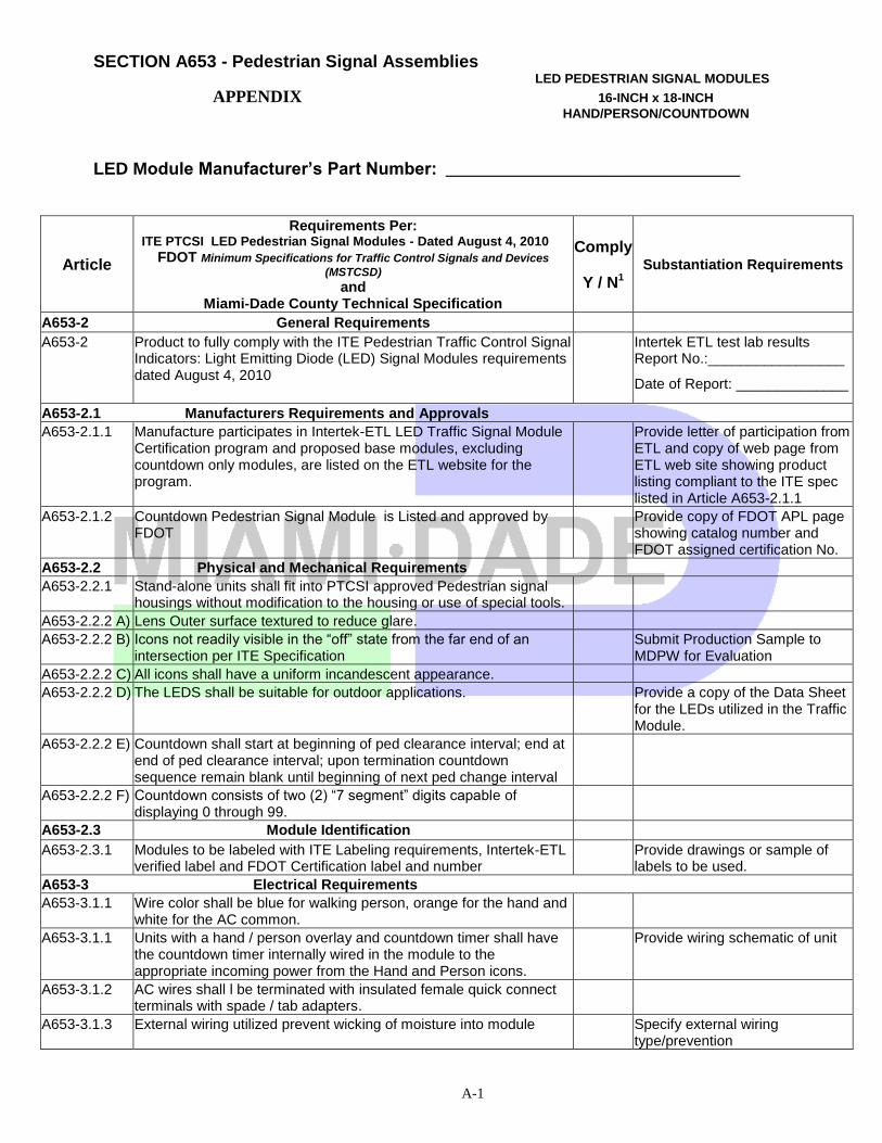
LED Module Manufacturer’s Part Number: __________________________________
Article
Requirements Per: ITE PTCSI LED Pedestrian Signal Modules - Dated August 4, 2010
FDOT Minimum Specifications for Traffic Control Signals and Devices
(MSTCSD) and
Miami-Dade County Technical Specification
Comply
Y / N1 Substantiation Requirements
A653-2 General Requirements
A653-2 Product to fully comply with the ITE Pedestrian Traffic Control Signal Indicators: Light Emitting Diode (LED) Signal Modules requirements dated August 4, 2010
Intertek ETL test lab results Report No.:_________________
Date of Report: ______________
A653-2.1 Manufacturers Requirements and Approvals
A653-2.1.1 Manufacture participates in Intertek-ETL LED Traffic Signal Module Certification program and proposed base modules, excluding countdown only modules, are listed on the ETL website for the program.
Provide letter of participation from ETL and copy of web page from ETL web site showing product listing compliant to the ITE spec listed in Article A653-2.1.1
A653-2.1.2 Countdown Pedestrian Signal Module is Listed and approved by FDOT
Provide copy of FDOT APL page showing catalog number and FDOT assigned certification No.
A653-2.2 Physical and Mechanical Requirements
A653-2.2.1 Stand-alone units shall fit into PTCSI approved Pedestrian signal housings without modification to the housing or use of special tools.
A653-2.2.2 A) Lens Outer surface textured to reduce glare.
A653-2.2.2 B) Icons not readily visible in the “off” state from the far end of an intersection per ITE Specification
Submit Production Sample to MDPW for Evaluation
A653-2.2.2 C) All icons shall have a uniform incandescent appearance.
A653-2.2.2 D) The LEDS shall be suitable for outdoor applications. Provide a copy of the Data Sheet for the LEDs utilized in the Traffic Module.
A653-2.2.2 E) Countdown shall start at beginning of ped clearance interval; end at end of ped clearance interval; upon termination countdown sequence remain blank until beginning of next ped change interval
A653-2.2.2 F) Countdown consists of two (2) “7 segment” digits capable of displaying 0 through 99.
A653-2.3 Module Identification
A653-2.3.1 Modules to be labeled with ITE Labeling requirements, Intertek-ETL verified label and FDOT Certification label and number
Provide drawings or sample of labels to be used.
A653-3 Electrical Requirements
A653-3.1.1 Wire color shall be blue for walking person, orange for the hand and white for the AC common.
A653-3.1.1 Units with a hand / person overlay and countdown timer shall have the countdown timer internally wired in the module to the appropriate incoming power from the Hand and Person icons.
Provide wiring schematic of unit
A653-3.1.2 AC wires shall l be terminated with insulated female quick connect terminals with spade / tab adapters.
A653-3.1.3 External wiring utilized prevent wicking of moisture into module Specify external wiring type/prevention
A-2
SECTION A653 - Pedestrian Signal Assemblies
LED PEDESTRIAN SIGNAL MODULES
APPENDIX 16-INCH x 18-INCH HAND/PERSON/COUNTDOWN
Article Comply
Y / N1
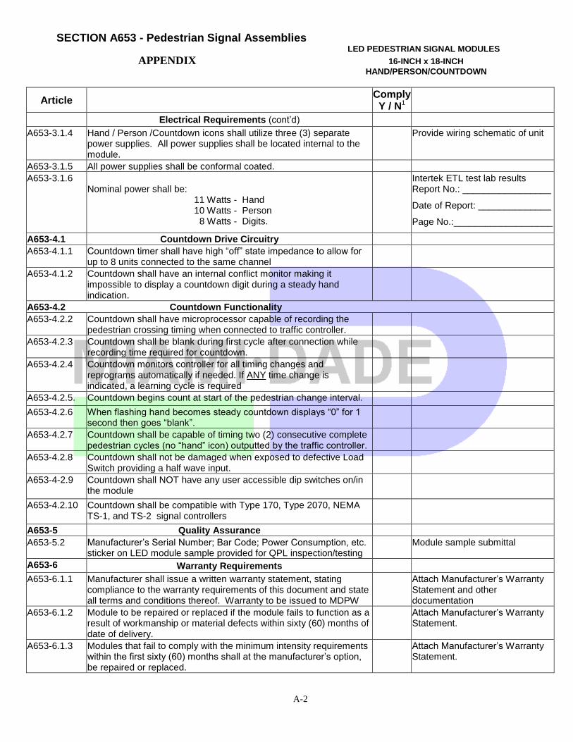
Electrical Requirements (cont’d)
A653-3.1.4 Hand / Person /Countdown icons shall utilize three (3) separate power supplies. All power supplies shall be located internal to the module.
Provide wiring schematic of unit
A653-3.1.5 All power supplies shall be conformal coated.
A653-3.1.6 Nominal power shall be: 11 Watts - Hand 10 Watts - Person 8 Watts - Digits.
Intertek ETL test lab results Report No.: _________________
Date of Report: ______________
Page No.:___________________
A653-4.1 Countdown Drive Circuitry
A653-4.1.1 Countdown timer shall have high “off” state impedance to allow for up to 8 units connected to the same channel
A653-4.1.2 Countdown shall have an internal conflict monitor making it impossible to display a countdown digit during a steady hand indication.
A653-4.2 Countdown Functionality
A653-4.2.2 Countdown shall have microprocessor capable of recording the pedestrian crossing timing when connected to traffic controller.
A653-4.2.3 Countdown shall be blank during first cycle after connection while recording time required for countdown.
A653-4.2.4 Countdown monitors controller for all timing changes and reprograms automatically if needed. If ANY time change is indicated, a learning cycle is required
A653-4.2.5. Countdown begins count at start of the pedestrian change interval.
A653-4.2.6 When flashing hand becomes steady countdown displays “0” for 1 second then goes “blank”.
A653-4.2.7 Countdown shall be capable of timing two (2) consecutive complete pedestrian cycles (no “hand” icon) outputted by the traffic controller.
A653-4.2.8 Countdown shall not be damaged when exposed to defective Load Switch providing a half wave input.
A653-4-2.9 Countdown shall NOT have any user accessible dip switches on/in the module
A653-4.2.10 Countdown shall be compatible with Type 170, Type 2070, NEMA TS-1, and TS-2 signal controllers
A653-5 Quality Assurance
A653-5.2 Manufacturer’s Serial Number; Bar Code; Power Consumption, etc. sticker on LED module sample provided for QPL inspection/testing
Module sample submittal
A653-6 Warranty Requirements
A653-6.1.1 Manufacturer shall issue a written warranty statement, stating compliance to the warranty requirements of this document and state all terms and conditions thereof. Warranty to be issued to MDPW
Attach Manufacturer’s Warranty Statement and other documentation
A653-6.1.2 Module to be repaired or replaced if the module fails to function as a result of workmanship or material defects within sixty (60) months of date of delivery.
Attach Manufacturer’s Warranty Statement.
A653-6.1.3 Modules that fail to comply with the minimum intensity requirements within the first sixty (60) months shall at the manufacturer’s option, be repaired or replaced.
Attach Manufacturer’s Warranty Statement.
A-3
SECTION A653 - Pedestrian Signal Assemblies
APPENDIX LED PEDESTRIAN SIGNAL MODULES
16-INCH x 18-INCH HAND/PERSON/COUNTDOWN
Article Comply
Y / N1
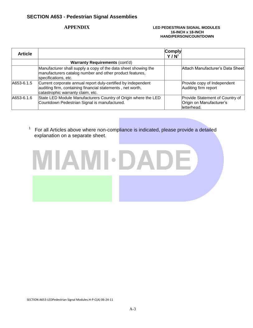
Warranty Requirements (cont’d)
Manufacturer shall supply a copy of the data sheet showing the manufacturers catalog number and other product features, specifications, etc.
Attach Manufacturer’s Data Sheet
A653-6.1.5 Current corporate annual report duly-certified by independent auditing firm, containing financial statements , net worth, catastrophic warranty claim, etc.
Provide copy of Independent Auditing firm report
A653-6.1.6 State LED Module Manufacturers Country of Origin where the LED Countdown Pedestrian Signal is manufactured.
Provide Statement of Country of Origin on Manufacturer’s letterhead.
1 For all Articles above where non-compliance is indicated, please provide a detailed explanation on a separate sheet.
SECTION A653-LEDPedestrian Signal Modules.H-P-C(A) 06-24-11