Embed Size (px)
Citation preview
SIGNALS AND LIGHTING FIELD GUIDE
Accessible Pedestrian Signal Push Buttons 18-1
CHAPTER 18 – ACCESSIBLE PEDESTRIAN SIGNAL PUSH BUTTONS
ACCESSIBLE PEDESTRIAN SIGNAL PUSH BUTTONS Accessible pedestrian signal (APS) push buttons inform the traffic control signal controller located in the traffic control signal cabinet that pedestrians wish to cross at the intersection. Pedestrian instruction signs including braille messages, pedestrian indications, and APS pushbuttons provide information to pedestrians wishing to cross the roadway at an intersection.
APS push buttons must be MnDOT approved and listed on MnDOT’s Approved/Qualified Products List (APL) for signals.
For new traffic control signal systems with pedestrian signal indications an APS must be installed.
MnDOT is also retrofitting in-place traffic control signal systems with APS systems.
18.1 APS
The contractor must ensure that the MnDOT completed order form, provided in the contract documents, is presented to the APS system manufacturer to ensure that the appropriate braille message will be added to the information sign and that the correct voice messages will be programmed in the pedestrian push button unit.
Each button and sign should arrive on the job site with identifying markings allowing the installer to place the buttons in their proper location. Additionally, each R10-3e retro reflective information sign should have a maintenance label on the backside printed in English defining the braille message presented on the front of the sign.
The contractor must refer to the contract documents for button locations and all additional requirements for the APS system.
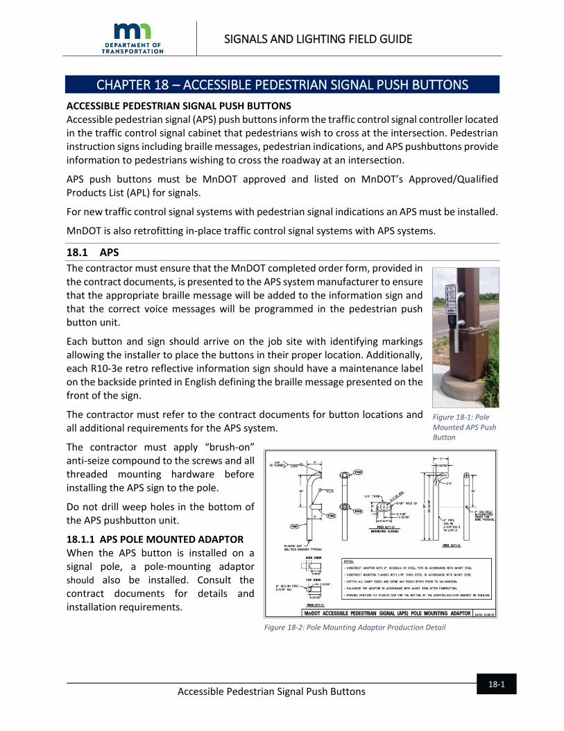
The contractor must apply “brush-on” anti-seize compound to the screws and all threaded mounting hardware before installing the APS sign to the pole.
Do not drill weep holes in the bottom of the APS pushbutton unit.
18.1.1 APS POLE MOUNTED ADAPTOR When the APS button is installed on a signal pole, a pole-mounting adaptor should also be installed. Consult the contract documents for details and installation requirements.
Figure 18-1: Pole Mounted APS Push Button
Figure 18-2: Pole Mounting Adaptor Production Detail
SIGNALS AND LIGHTING FIELD GUIDE
Accessible Pedestrian Signal Push Buttons 18-2
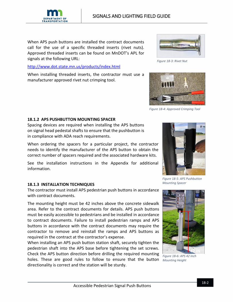
When APS push buttons are installed the contract documents call for the use of a specific threaded inserts (rivet nuts). Approved threaded inserts can be found on MnDOT’s APL for signals at the following URL:
http://www.dot.state.mn.us/products/index.html
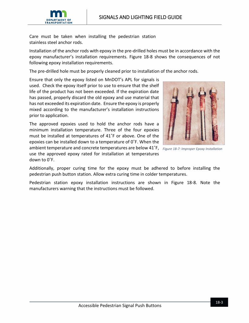
When installing threaded inserts, the contractor must use a manufacturer approved rivet nut crimping tool.
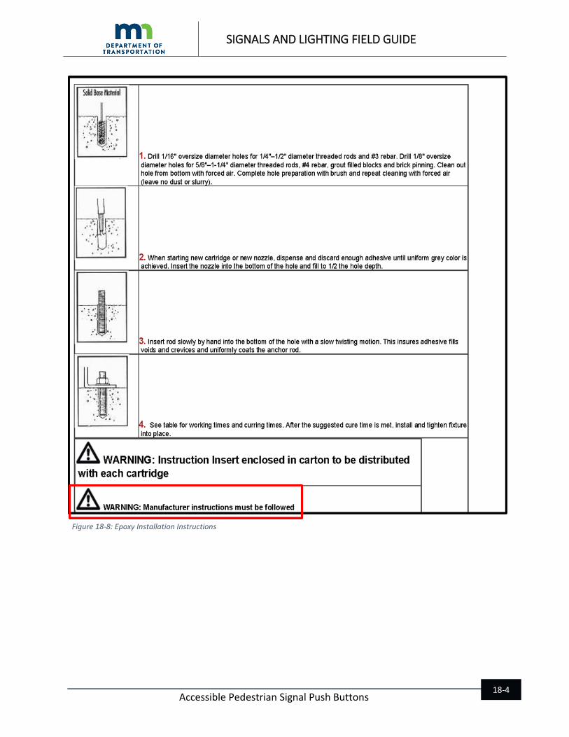
18.1.2 APS PUSHBUTTON MOUNTING SPACER Spacing devices are required when installing the APS buttons on signal head pedestal shafts to ensure that the pushbutton is in compliance with ADA reach requirements.
When ordering the spacers for a particular project, the contractor needs to identify the manufacturer of the APS button to obtain the correct number of spacers required and the associated hardware kits.
See the installation instructions in the Appendix for additional information.
18.1.3 INSTALLATION TECHNIQUES The contractor must install APS pedestrian push buttons in accordance with contract documents.
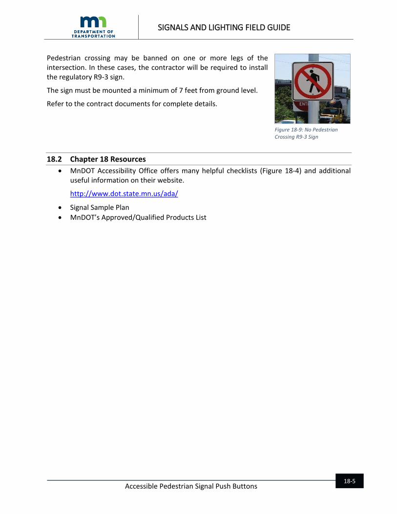
The mounting height must be 42 inches above the concrete sidewalk area. Refer to the contract documents for details. APS push buttons must be easily accessible to pedestrians and be installed in accordance to contract documents. Failure to install pedestrian ramps and APS buttons in accordance with the contract documents may require the contractor to remove and reinstall the ramps and APS buttons as required in the contract at the contractor’s expense. When installing an APS push button station shaft, securely tighten the pedestrian shaft into the APS base before tightening the set screws. Check the APS button direction before drilling the required mounting holes. These are good rules to follow to ensure that the button directionality is correct and the station will be sturdy.
Figure 18-3: Rivet Nut
Figure 18-4: Approved Crimping Tool
Figure 18-5: APS Pushbutton Mounting Spacer
Figure 18-6: APS 42 Inch Mounting Height
42 IN
SIGNALS AND LIGHTING FIELD GUIDE
Accessible Pedestrian Signal Push Buttons 18-3
Care must be taken when installing the pedestrian station stainless steel anchor rods.
Installation of the anchor rods with epoxy in the pre-drilled holes must be in accordance with the epoxy manufacturer’s installation requirements. Figure 18-8 shows the consequences of not following epoxy installation requirements.
The pre-drilled hole must be properly cleaned prior to installation of the anchor rods.
Ensure that only the epoxy listed on MnDOT’s APL for signals is used. Check the epoxy itself prior to use to ensure that the shelf life of the product has not been exceeded. If the expiration date has passed, properly discard the old epoxy and use material that has not exceeded its expiration date. Ensure the epoxy is properly mixed according to the manufacturer’s installation instructions prior to application.
The approved epoxies used to hold the anchor rods have a minimum installation temperature. Three of the four epoxies must be installed at temperatures of 41˚F or above. One of the epoxies can be installed down to a temperature of 0˚F. When the ambient temperature and concrete temperatures are below 41˚F, use the approved epoxy rated for installation at temperatures down to 0˚F.
Additionally, proper curing time for the epoxy must be adhered to before installing the pedestrian push button station. Allow extra curing time in colder temperatures.
Pedestrian station epoxy installation instructions are shown in Figure 18-8. Note the manufacturers warning that the instructions must be followed.
Figure 18-7: Improper Epoxy Installation
SIGNALS AND LIGHTING FIELD GUIDE
Accessible Pedestrian Signal Push Buttons 18-4
Figure 18-8: Epoxy Installation Instructions
SIGNALS AND LIGHTING FIELD GUIDE
Accessible Pedestrian Signal Push Buttons 18-5
Pedestrian crossing may be banned on one or more legs of the intersection. In these cases, the contractor will be required to install the regulatory R9-3 sign.
The sign must be mounted a minimum of 7 feet from ground level.
Refer to the contract documents for complete details.
18.2 Chapter 18 Resources
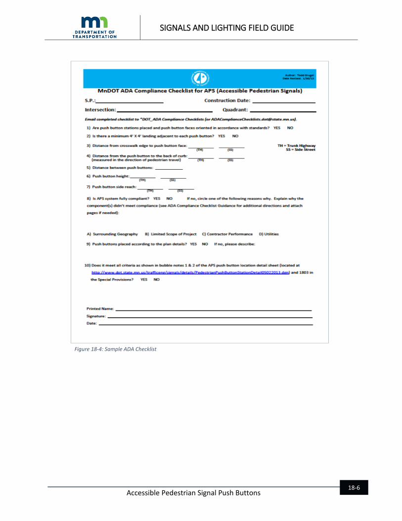
MnDOT Accessibility Office offers many helpful checklists (Figure 18-4) and additional useful information on their website.
http://www.dot.state.mn.us/ada/
Signal Sample Plan
MnDOT’s Approved/Qualified Products List
Figure 18-9: No Pedestrian Crossing R9-3 Sign
SIGNALS AND LIGHTING FIELD GUIDE
Accessible Pedestrian Signal Push Buttons 18-6
Figure 18-4: Sample ADA Checklist