Embed Size (px)
Citation preview
CO-1
ENGINE COOLING SYSTEM
B ENGINE
CONTENTS
C
D
E
F
G
H
I
J
K
L
M
SECTION
A
CO
KA24DE
PRECAUTIONS .......................................................... 3Precautions for Supplemental Restraint System (SRS) “AIR BAG” and “SEAT BELT PRE-TEN-SIONER” .................................................................. 3Precautions for Liquid Gasket .................................. 3
REMOVAL OF LIQUID GASKET .......................... 3LIQUID GASKET APPLICATION PROCEDURE ..... 4
PREPARATION ........................................................... 5Special Service Tools ............................................... 5
OVERHEATING CAUSE ANALYSIS .......................... 6Troubleshooting Chart .............................................. 6
COOLING SYSTEM .................................................... 7Cooling Circuit .......................................................... 7
ENGINE COOLANT .................................................... 8System Check .......................................................... 8
CHECKING COOLING SYSTEM HOSES ............ 8CHECKING RADIATOR ........................................ 8CHECKING COOLING SYSTEM FOR LEAKS ..... 8CHECKING RADIATOR CAP ................................ 8
Refilling Engine Coolant ........................................... 9WATER PUMP .......................................................... 10
Removal ................................................................. 10Inspection ................................................................11Installation ...............................................................11
THERMOSTAT .......................................................... 13Removal ................................................................. 13Inspection ............................................................... 13Installation .............................................................. 13
RADIATOR ................................................................ 14Components ........................................................... 14Removal and Installation ........................................ 14Inspection ............................................................... 15
COOLING FAN (CRANKSHAFT DRIVEN) .............. 16Removal and Installation ........................................ 16Inspection ............................................................... 16
SERVICE DATA AND SPECIFICATIONS (SDS) ...... 17Thermostat ............................................................. 17Radiator .................................................................. 17
VG33E and VG33ER
PRECAUTIONS ........................................................ 18Precautions for Supplemental Restraint System (SRS) “AIR BAG” and “SEAT BELT PRE-TEN-SIONER” ................................................................. 18Precautions for Liquid Gasket ................................ 18
REMOVAL OF LIQUID GASKET ......................... 18Precautions for Liquid Gasket ................................ 19
REMOVAL OF LIQUID GASKET ......................... 19LIQUID GASKET APPLICATION PROCEDURE ... 19
PREPARATION ......................................................... 20Special Service Tools ............................................. 20
OVERHEATING CAUSE ANALYSIS ........................ 21Troubleshooting Chart ............................................ 21
COOLING SYSTEM .................................................. 22Cooling Circuit ........................................................ 22
ENGINE COOLANT .................................................. 23System Check ........................................................ 23
CHECKING COOLING SYSTEM HOSES ........... 23CHECKING RADIATOR ...................................... 23CHECKING COOLING SYSTEM FOR LEAKS ... 23CHECKING RADIATOR CAP .............................. 23
Refilling Engine Coolant ......................................... 24WATER PUMP .......................................................... 25
Removal ................................................................. 25Inspection ............................................................... 26Installation .............................................................. 26
THERMOSTAT .......................................................... 28Removal ................................................................. 28Inspection ............................................................... 28Installation .............................................................. 29
RADIATOR ................................................................ 30Components ........................................................... 30Removal and Installation ........................................ 30Inspection ............................................................... 31
COOLING FAN (CRANKSHAFT DRIVEN) ............... 32Removal and Installation ........................................ 32Inspection ............................................................... 32
CO-2
SERVICE DATA AND SPECIFICATIONS (SDS) ...... 33Thermostat .............................................................. 33Radiator .................................................................. 33
PRECAUTIONS
CO-3
[KA24DE]
C
D
E
F
G
H
I
J
K
L
M
A
CO
PRECAUTIONS PFP:00001
Precautions for Supplemental Restraint System (SRS) “AIR BAG” and “SEAT BELT PRE-TENSIONER” EBS00EZP
The Supplemental Restraint System such as “AIR BAG” and “SEAT BELT PRE-TENSIONER”, used alongwith a front seat belt, helps to reduce the risk or severity of injury to the driver and front passenger for certaintypes of collision. This system may include seat belt switch inputs and dual stage front air bag modules. Ifequipped with dual stage front air bag modules, the SRS system uses the seat belt switches to determine thefront air bag deployment, and may only deploy one front air bag, depending on the severity of a collision andwhether the front occupants are belted or unbelted. Information necessary to service the system safely isincluded in the SRS and SB section of this Service Manual.
The vehicle may be equipped with a passenger air bag deactivation switch. Because no rear seat exists wherea rear-facing child restraint can be placed, the switch is designed to turn off the passenger air bag so that arear-facing child restraint can be used in the front passenger seat. The switch is located in the center of theinstrument panel, near the ashtray. When the switch is turned to the ON position, the passenger air bag isenabled and could inflate for certain types of collision. When the switch is turned to the OFF position, the pas-senger air bag is disabled and will not inflate. A passenger air bag OFF indicator on the instrument panel lightsup when the passenger air bag is switched OFF. The driver air bag always remains enabled and is not affectedby the passenger air bag deactivation switch.
WARNING:● To avoid rendering the SRS inoperative, which could increase the risk of personal injury or death
in the event of a collision which would result in air bag inflation, all maintenance must be per-formed by an authorized NISSAN/INFINITI dealer.
● Improper maintenance, including incorrect removal and installation of the SRS, can lead to per-sonal injury caused by unintentional activation of the system. For removal of Spiral Cable and AirBag Module, see the SRS section.
● Do not use electrical test equipment on any circuit related to the SRS unless instructed to in thisService Manual. SRS wiring harnesses can be identified by yellow and/or orange harnesses orharness connectors.
● The vehicle may be equipped with a passenger air bag deactivation switch which can be operatedby the customer. When the passenger air bag is switched OFF, the passenger air bag is disabledand will not inflate. When the passenger air bag is switched ON, the passenger air bag is enabledand could inflate for certain types of collision. After SRS maintenance or repair, make sure thepassenger air bag deactivation switch is in the same position (ON or OFF) as when the vehiclearrived for service.
Precautions for Liquid Gasket EBS00EZQ
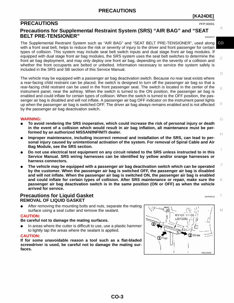
REMOVAL OF LIQUID GASKET● After removing the mounting bolts and nuts, separate the mating
surface using a seal cutter and remove the sealant. CAUTION:Be careful not to damage the mating surfaces.● In areas where the cutter is difficult to use, use a plastic hammer
to lightly tap the areas where the sealant is applied.CAUTION:If for some unavoidable reason a tool such as a flat-bladedscrewdriver is used, be careful not to damage the mating sur-faces.
PBIC0002E
CO-4
[KA24DE]PRECAUTIONS
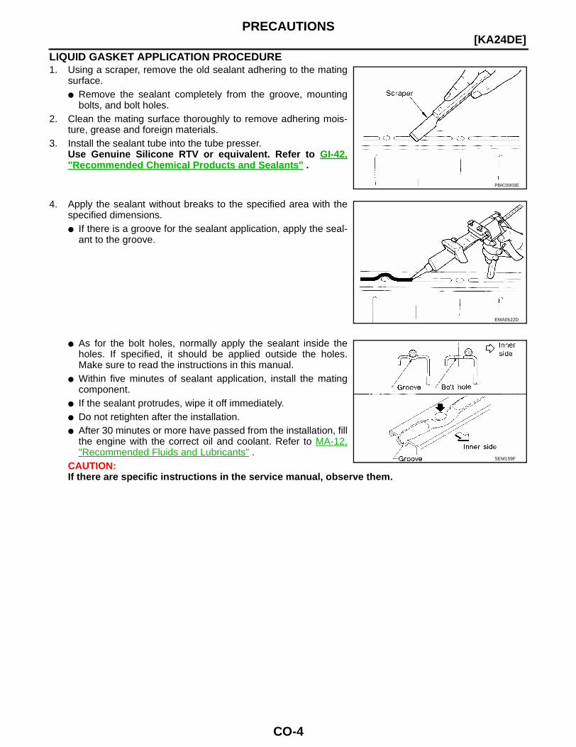
LIQUID GASKET APPLICATION PROCEDURE1. Using a scraper, remove the old sealant adhering to the mating
surface.● Remove the sealant completely from the groove, mounting
bolts, and bolt holes.2. Clean the mating surface thoroughly to remove adhering mois-
ture, grease and foreign materials.3. Install the sealant tube into the tube presser.
Use Genuine Silicone RTV or equivalent. Refer to GI-42,"Recommended Chemical Products and Sealants" .
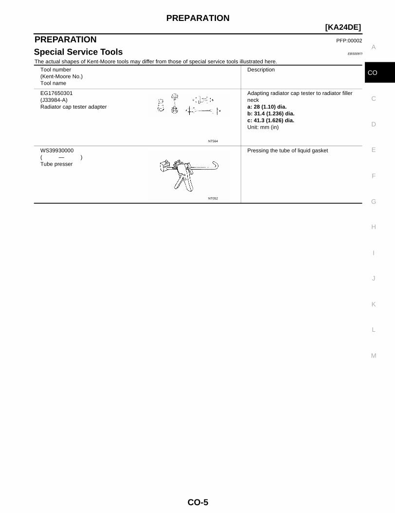
4. Apply the sealant without breaks to the specified area with thespecified dimensions.● If there is a groove for the sealant application, apply the seal-
ant to the groove.
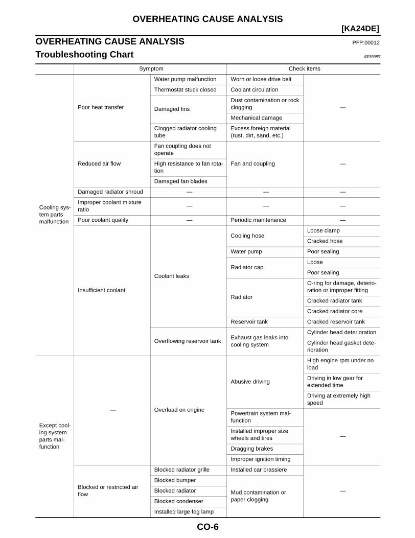
● As for the bolt holes, normally apply the sealant inside theholes. If specified, it should be applied outside the holes.Make sure to read the instructions in this manual.
● Within five minutes of sealant application, install the matingcomponent.
● If the sealant protrudes, wipe it off immediately.● Do not retighten after the installation.● After 30 minutes or more have passed from the installation, fill
the engine with the correct oil and coolant. Refer to MA-12,"Recommended Fluids and Lubricants" .
CAUTION:If there are specific instructions in the service manual, observe them.
PBIC0003E
EMA0622D
SEM159F
PREPARATION
CO-5
[KA24DE]
C
D
E
F
G
H
I
J
K
L
M
A
CO
PREPARATION PFP:00002
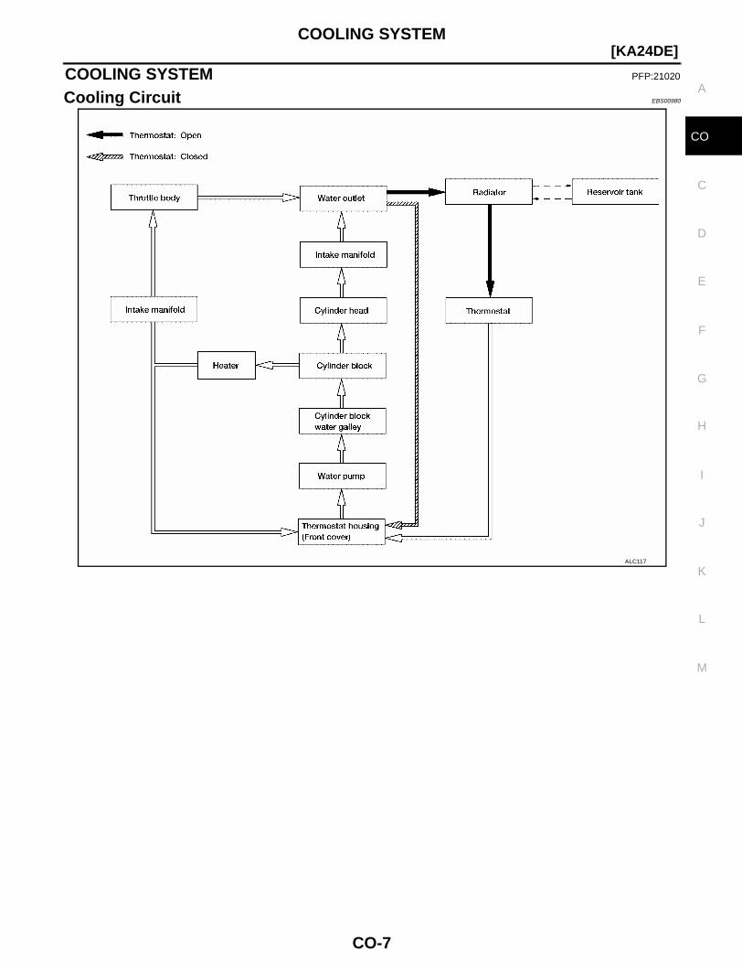
Special Service Tools EBS0097I
The actual shapes of Kent-Moore tools may differ from those of special service tools illustrated here.
Tool number(Kent-Moore No.)Tool name
Description
EG17650301(J33984-A)Radiator cap tester adapter
Adapting radiator cap tester to radiator filler necka: 28 (1.10) dia.b: 31.4 (1.236) dia.c: 41.3 (1.626) dia.Unit: mm (in)
WS39930000( — )Tube presser
Pressing the tube of liquid gasket
NT564
NT052
CO-6
[KA24DE]OVERHEATING CAUSE ANALYSIS
OVERHEATING CAUSE ANALYSIS PFP:00012
Troubleshooting Chart EBS00983
Symptom Check items
Cooling sys-tem parts malfunction
Poor heat transfer
Water pump malfunction Worn or loose drive belt
—
Thermostat stuck closed Coolant circulation
Damaged fins
Dust contamination or rock clogging
Mechanical damage
Clogged radiator cooling tube
Excess foreign material (rust, dirt, sand, etc.)
Reduced air flow
Fan coupling does not operate
Fan and coupling —High resistance to fan rota-tion
Damaged fan blades
Damaged radiator shroud — — —
Improper coolant mixture ratio
— — —
Poor coolant quality — Periodic maintenance —
Insufficient coolant
Coolant leaks
Cooling hoseLoose clamp
Cracked hose
Water pump Poor sealing
Radiator capLoose
Poor sealing
Radiator
O-ring for damage, deterio-ration or improper fitting
Cracked radiator tank
Cracked radiator core
Reservoir tank Cracked reservoir tank
Overflowing reservoir tankExhaust gas leaks into cooling system
Cylinder head deterioration
Cylinder head gasket dete-rioration
Except cool-ing system parts mal-function
— Overload on engine
Abusive driving
High engine rpm under no load
Driving in low gear for extended time
Driving at extremely high speed
Powertrain system mal-function
—Installed improper size wheels and tires
Dragging brakes
Improper ignition timing
Blocked or restricted air flow
Blocked radiator grille Installed car brassiere
—Mud contamination or paper clogging
Blocked bumper
Blocked radiator
Blocked condenser
Installed large fog lamp
COOLING SYSTEM
CO-7
[KA24DE]
C
D
E
F
G
H
I
J
K
L
M
A
CO
COOLING SYSTEM PFP:21020
Cooling Circuit EBS00980
ALC117
CO-8
[KA24DE]ENGINE COOLANT
ENGINE COOLANT PFP:KQ100
System Check EBS00981
WARNING:● Never remove the radiator cap when the engine is hot. Serious burns could occur from high pres-
sure coolant escaping from the radiator.● Wrap a thick cloth around the radiator cap. Slowly turn it a quarter turn to allow built-up pressure
to escape. Carefully remove the radiator cap by turning it all the way.
CHECKING COOLING SYSTEM HOSES● Check hoses for improper attachment, leaks, cracks, damage, chafing and deterioration.
CHECKING RADIATORCheck radiator for mud or clogging. If necessary, clean radiator as follows:CAUTION:● Be careful not to bend or damage the radiator fins.● When radiator is cleaned without removal, remove all surrounding parts such as cooling fan, radi-
ator shroud and horns.● Tape the harness connectors to prevent water from entering.1. Apply water by hose to the back side of the radiator core vertically downward.2. Apply water again to all radiator core surfaces once per minute.3. Stop washing when water flows clear coming out of the radiator.4. Blow air into the back side of radiator core vertically downward.
● Use compressed air lower than 490 kPa (5 kg/cm2 , 71 psi) and keep the air hose end more than 30 cm(11.8 in) away from the core.
5. Blow air again into all the radiator core surfaces once per minute until no water blows out and the core isdry.
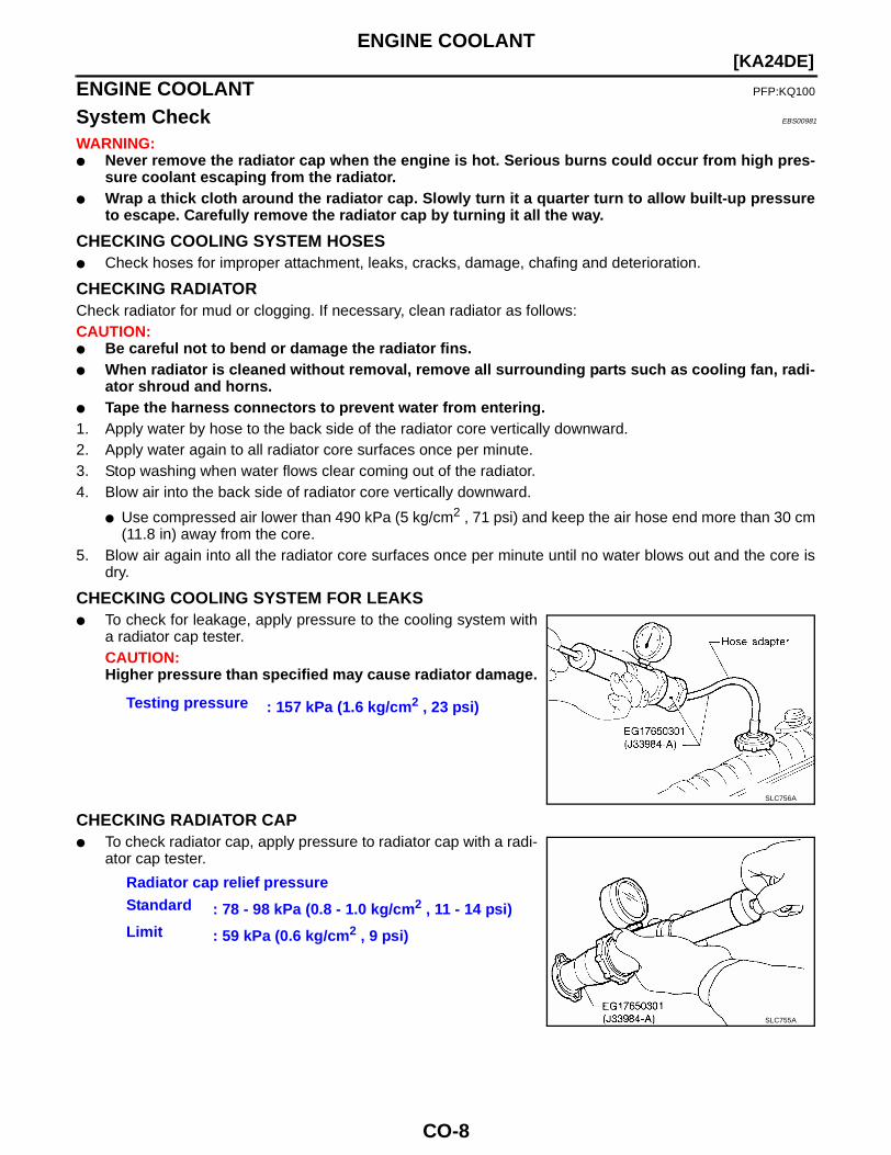
CHECKING COOLING SYSTEM FOR LEAKS● To check for leakage, apply pressure to the cooling system with
a radiator cap tester.CAUTION:Higher pressure than specified may cause radiator damage.
CHECKING RADIATOR CAP● To check radiator cap, apply pressure to radiator cap with a radi-
ator cap tester.
Testing pressure : 157 kPa (1.6 kg/cm2 , 23 psi)
SLC756A
Radiator cap relief pressureStandard : 78 - 98 kPa (0.8 - 1.0 kg/cm2 , 11 - 14 psi)Limit : 59 kPa (0.6 kg/cm2 , 9 psi)
SLC755A
ENGINE COOLANT
CO-9
[KA24DE]
C
D
E
F
G
H
I
J
K
L
M
A
CO
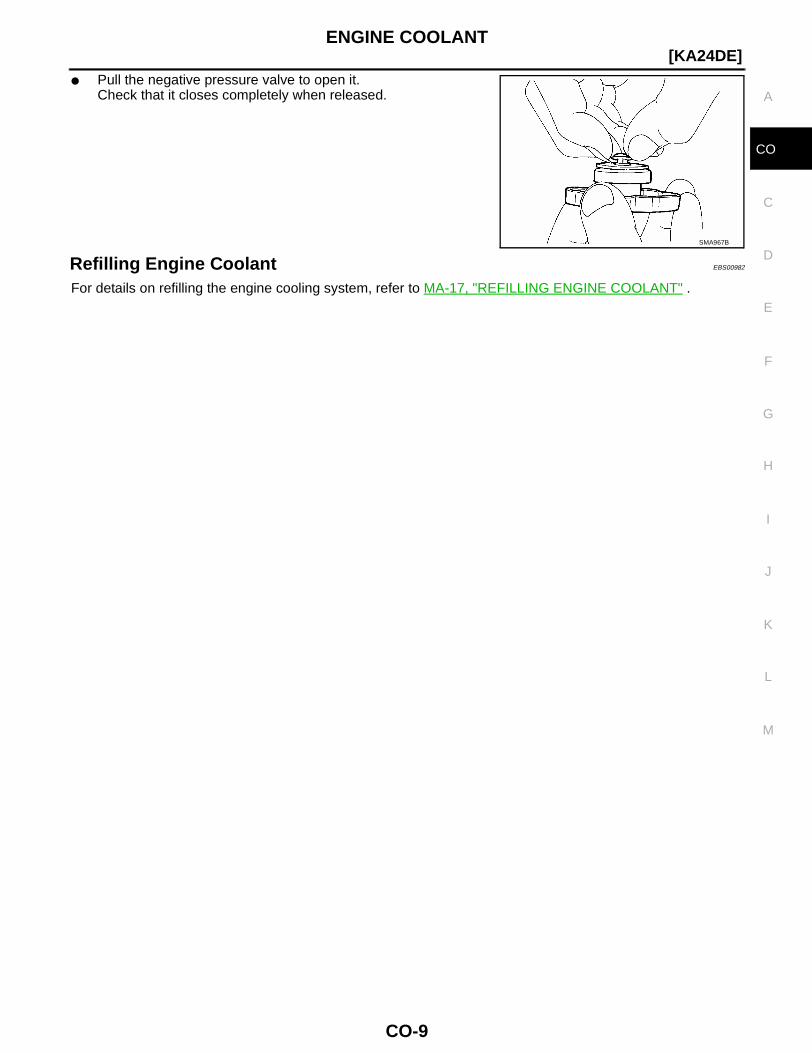
● Pull the negative pressure valve to open it.Check that it closes completely when released.
Refilling Engine Coolant EBS00982
For details on refilling the engine cooling system, refer to MA-17, "REFILLING ENGINE COOLANT" .
SMA967B

CO-10
[KA24DE]WATER PUMP
WATER PUMP PFP:21020
Removal EBS0097L
CAUTION:● When removing water pump assembly, be careful not to get coolant on drive belts.● Water pump cannot be disassembled and should be replaced as a unit.● After installing water pump, connect hose and clamp securely. Check for leaks using radiator cap
tester.1. Drain coolant from engine.
Refer to MA-16, "DRAINING ENGINE COOLANT" .2. Remove fan coupling with fan.3. Remove power steering pump drive belt, generator drive belt, and A/C compressor drive belt.4. Remove water pump pulley.5. Remove water pump.
1. Water inlet 2. Thermostat 3. Water pump
4. Water pump pulley 5. Fan coupling 6. Fan
WBIA0446E
WATER PUMP
CO-11
[KA24DE]
C
D
E
F
G
H
I
J
K
L
M
A
CO
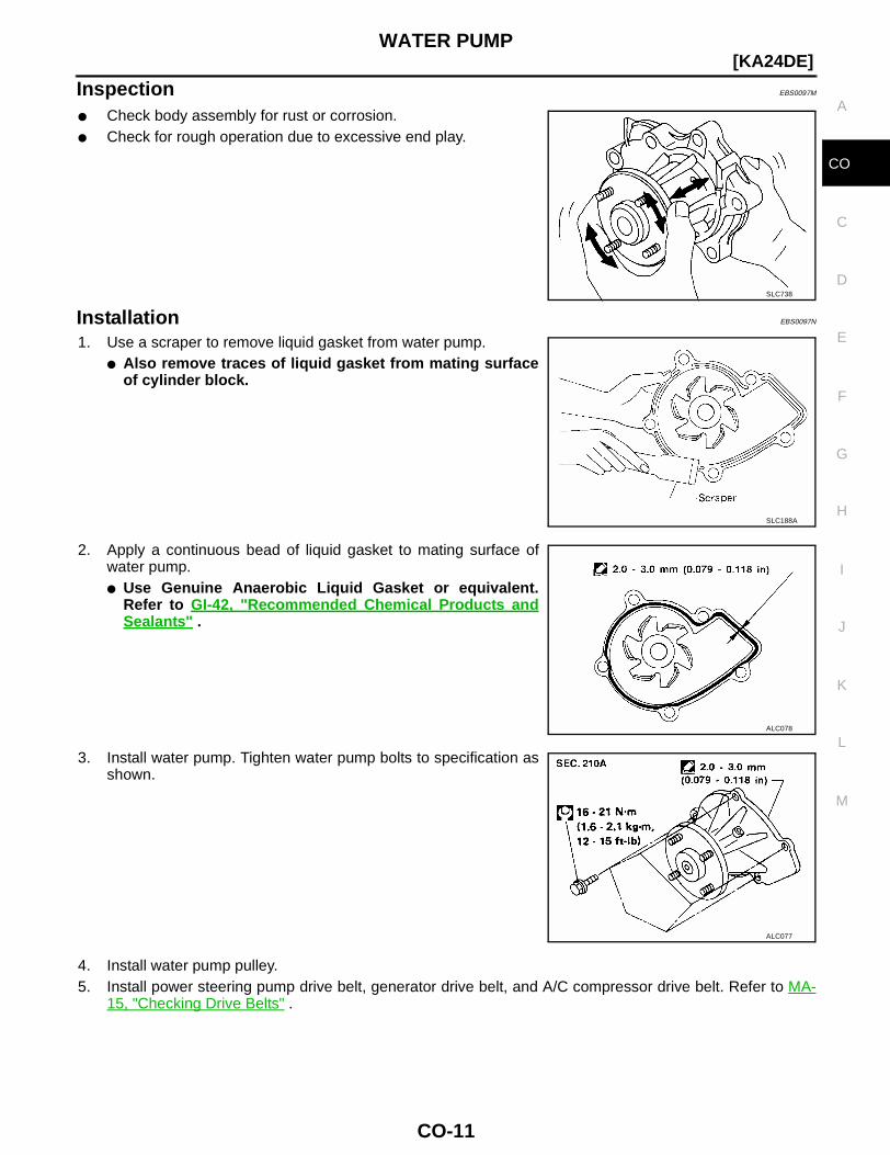
Inspection EBS0097M
● Check body assembly for rust or corrosion.● Check for rough operation due to excessive end play.
Installation EBS0097N
1. Use a scraper to remove liquid gasket from water pump.● Also remove traces of liquid gasket from mating surface
of cylinder block.
2. Apply a continuous bead of liquid gasket to mating surface ofwater pump.● Use Genuine Anaerobic Liquid Gasket or equivalent.
Refer to GI-42, "Recommended Chemical Products andSealants" .
3. Install water pump. Tighten water pump bolts to specification asshown.
4. Install water pump pulley.5. Install power steering pump drive belt, generator drive belt, and A/C compressor drive belt. Refer to MA-
15, "Checking Drive Belts" .
SLC738
SLC188A
ALC078
ALC077
CO-12
[KA24DE]WATER PUMP
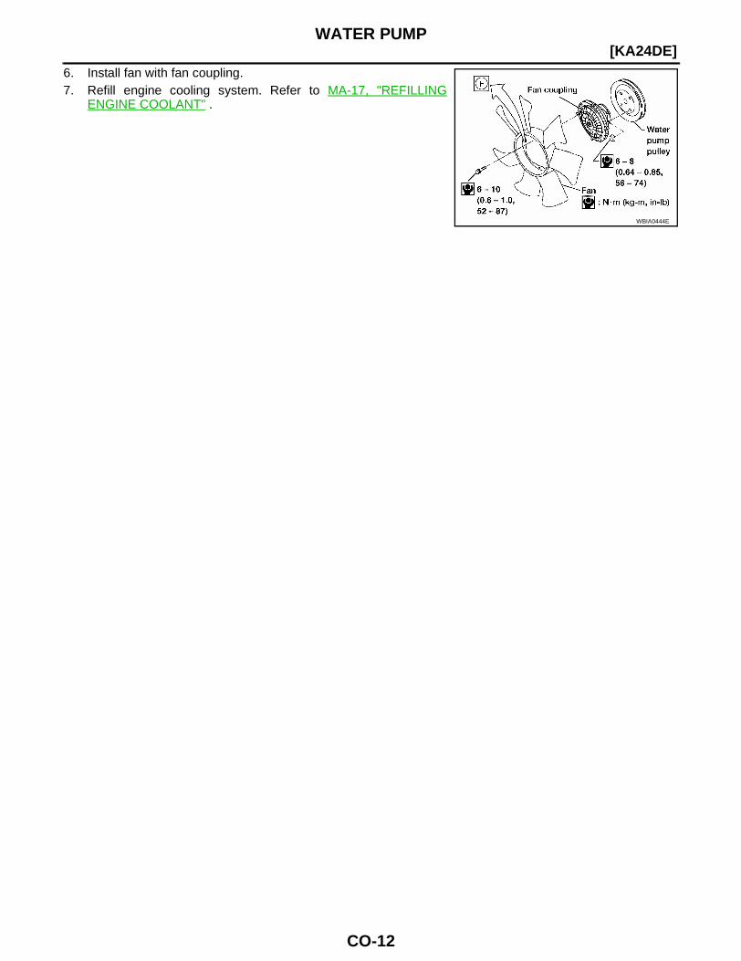
6. Install fan with fan coupling.7. Refill engine cooling system. Refer to MA-17, "REFILLING
ENGINE COOLANT" .
WBIA0444E
THERMOSTAT
CO-13
[KA24DE]
C
D
E
F
G
H
I
J
K
L
M
A
CO
THERMOSTAT PFP:21200
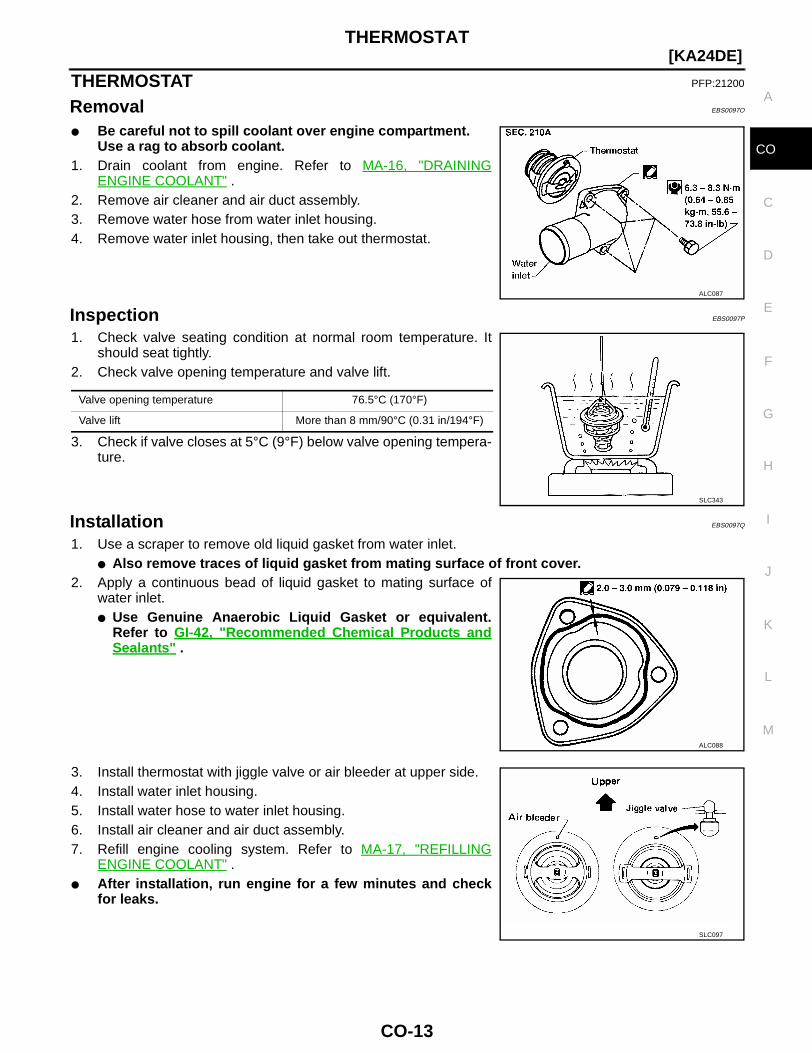
Removal EBS0097O
● Be careful not to spill coolant over engine compartment.Use a rag to absorb coolant.
1. Drain coolant from engine. Refer to MA-16, "DRAININGENGINE COOLANT" .
2. Remove air cleaner and air duct assembly.3. Remove water hose from water inlet housing.4. Remove water inlet housing, then take out thermostat.
Inspection EBS0097P
1. Check valve seating condition at normal room temperature. Itshould seat tightly.
2. Check valve opening temperature and valve lift.
3. Check if valve closes at 5°C (9°F) below valve opening tempera-ture.
Installation EBS0097Q
1. Use a scraper to remove old liquid gasket from water inlet.● Also remove traces of liquid gasket from mating surface of front cover.
2. Apply a continuous bead of liquid gasket to mating surface ofwater inlet.● Use Genuine Anaerobic Liquid Gasket or equivalent.
Refer to GI-42, "Recommended Chemical Products andSealants" .
3. Install thermostat with jiggle valve or air bleeder at upper side.4. Install water inlet housing.5. Install water hose to water inlet housing.6. Install air cleaner and air duct assembly.7. Refill engine cooling system. Refer to MA-17, "REFILLING
ENGINE COOLANT" .● After installation, run engine for a few minutes and check
for leaks.
ALC087
Valve opening temperature 76.5°C (170°F)
Valve lift More than 8 mm/90°C (0.31 in/194°F)
SLC343
ALC088
SLC097
CO-14
[KA24DE]RADIATOR
RADIATOR PFP:21400
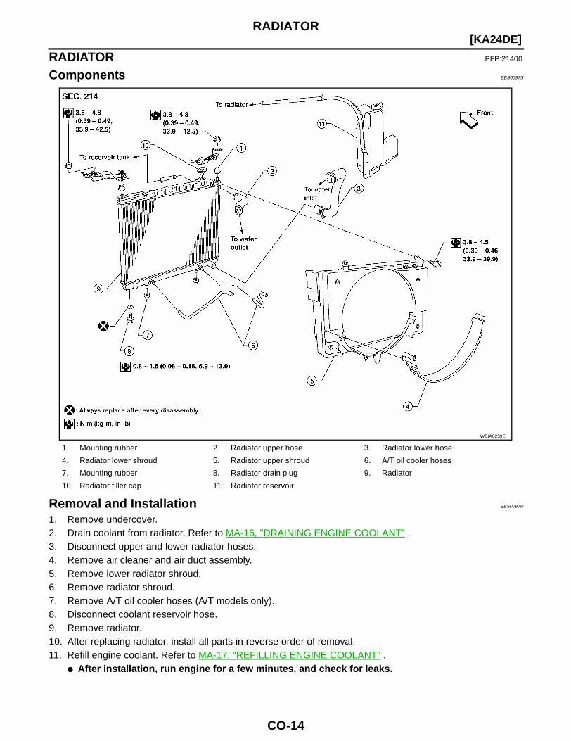
Components EBS0097S
Removal and Installation EBS0097R
1. Remove undercover.2. Drain coolant from radiator. Refer to MA-16, "DRAINING ENGINE COOLANT" .3. Disconnect upper and lower radiator hoses.4. Remove air cleaner and air duct assembly.5. Remove lower radiator shroud.6. Remove radiator shroud.7. Remove A/T oil cooler hoses (A/T models only).8. Disconnect coolant reservoir hose.9. Remove radiator.10. After replacing radiator, install all parts in reverse order of removal.11. Refill engine coolant. Refer to MA-17, "REFILLING ENGINE COOLANT" .
● After installation, run engine for a few minutes, and check for leaks.
1. Mounting rubber 2. Radiator upper hose 3. Radiator lower hose
4. Radiator lower shroud 5. Radiator upper shroud 6. A/T oil cooler hoses
7. Mounting rubber 8. Radiator drain plug 9. Radiator
10. Radiator filler cap 11. Radiator reservoir
WBIA0239E
RADIATOR
CO-15
[KA24DE]
C
D
E
F
G
H
I
J
K
L
M
A
CO
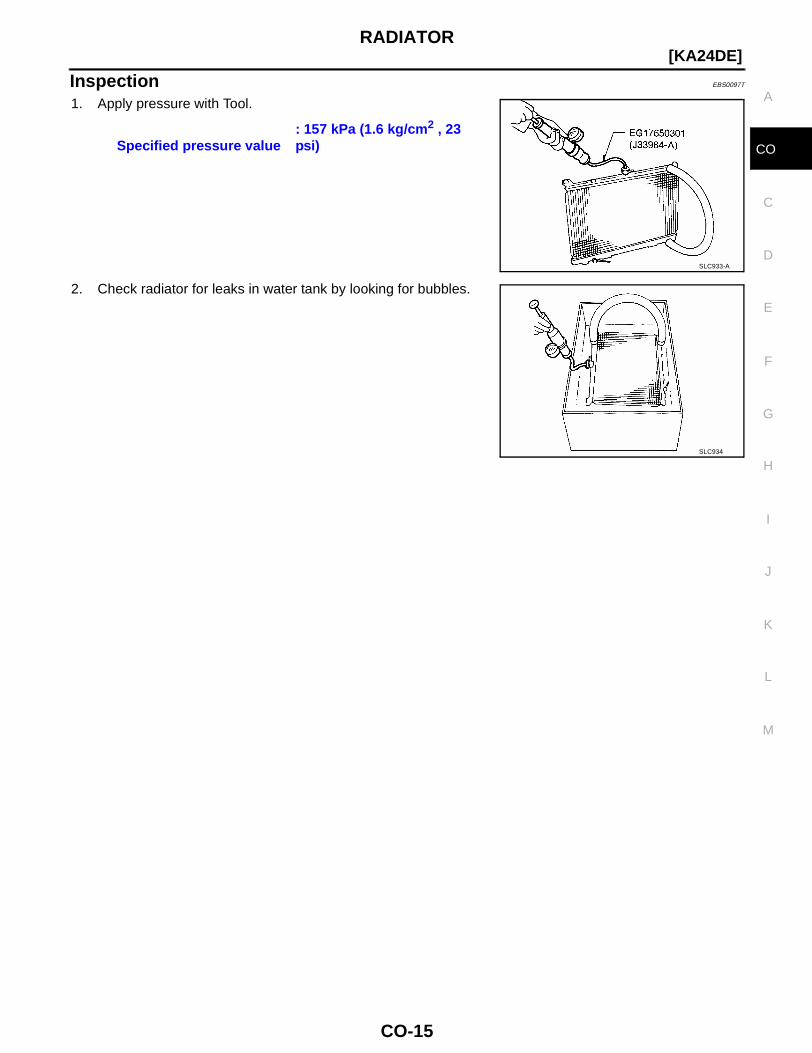
Inspection EBS0097T
1. Apply pressure with Tool.
2. Check radiator for leaks in water tank by looking for bubbles.
Specified pressure value: 157 kPa (1.6 kg/cm2 , 23 psi)
SLC933-A
SLC934
CO-16
[KA24DE]COOLING FAN (CRANKSHAFT DRIVEN)
COOLING FAN (CRANKSHAFT DRIVEN) PFP:21060
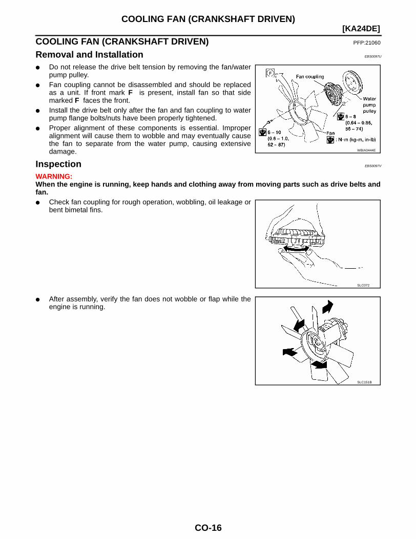
Removal and Installation EBS0097U
● Do not release the drive belt tension by removing the fan/waterpump pulley.
● Fan coupling cannot be disassembled and should be replacedas a unit. If front mark F is present, install fan so that sidemarked F faces the front.
● Install the drive belt only after the fan and fan coupling to waterpump flange bolts/nuts have been properly tightened.
● Proper alignment of these components is essential. Improperalignment will cause them to wobble and may eventually causethe fan to separate from the water pump, causing extensivedamage.
Inspection EBS0097V
WARNING:When the engine is running, keep hands and clothing away from moving parts such as drive belts andfan.● Check fan coupling for rough operation, wobbling, oil leakage or
bent bimetal fins.
● After assembly, verify the fan does not wobble or flap while theengine is running.
WBIA0444E
SLC072
SLC151B
SERVICE DATA AND SPECIFICATIONS (SDS)
CO-17
[KA24DE]
C
D
E
F
G
H
I
J
K
L
M
A
CO
SERVICE DATA AND SPECIFICATIONS (SDS) PFP:00030
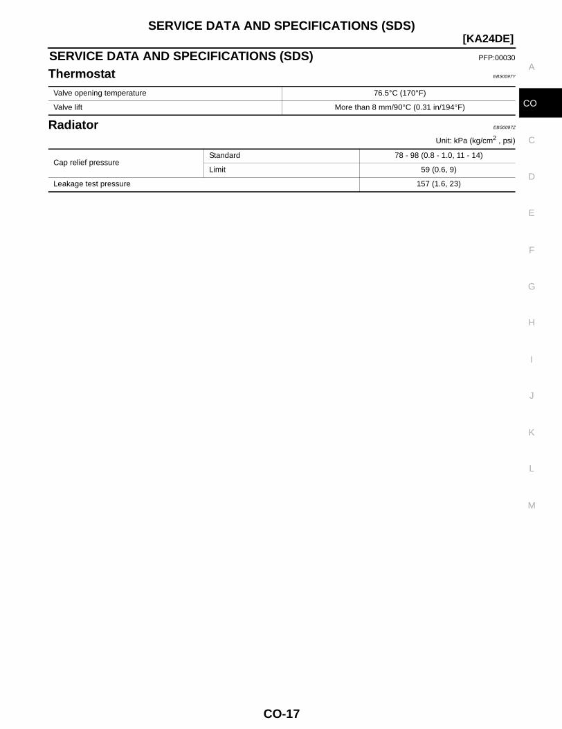
Thermostat EBS0097Y
Radiator EBS0097Z
Unit: kPa (kg/cm2 , psi)
Valve opening temperature 76.5°C (170°F)
Valve lift More than 8 mm/90°C (0.31 in/194°F)
Cap relief pressureStandard 78 - 98 (0.8 - 1.0, 11 - 14)
Limit 59 (0.6, 9)
Leakage test pressure 157 (1.6, 23)
CO-18
[VG33E and VG33ER]PRECAUTIONS
PRECAUTIONS PFP:00001
Precautions for Supplemental Restraint System (SRS) “AIR BAG” and “SEAT BELT PRE-TENSIONER” EBS00EZN
The Supplemental Restraint System such as “AIR BAG” and “SEAT BELT PRE-TENSIONER”, used alongwith a front seat belt, helps to reduce the risk or severity of injury to the driver and front passenger for certaintypes of collision. This system may include seat belt switch inputs and dual stage front air bag modules. Ifequipped with dual stage front air bag modules, the SRS system uses the seat belt switches to determine thefront air bag deployment, and may only deploy one front air bag, depending on the severity of a collision andwhether the front occupants are belted or unbelted. Information necessary to service the system safely isincluded in the SRS and SB section of this Service Manual.
The vehicle may be equipped with a passenger air bag deactivation switch. Because no rear seat exists wherea rear-facing child restraint can be placed, the switch is designed to turn off the passenger air bag so that arear-facing child restraint can be used in the front passenger seat. The switch is located in the center of theinstrument panel, near the ashtray. When the switch is turned to the ON position, the passenger air bag isenabled and could inflate for certain types of collision. When the switch is turned to the OFF position, the pas-senger air bag is disabled and will not inflate. A passenger air bag OFF indicator on the instrument panel lightsup when the passenger air bag is switched OFF. The driver air bag always remains enabled and is not affectedby the passenger air bag deactivation switch.
WARNING:● To avoid rendering the SRS inoperative, which could increase the risk of personal injury or death
in the event of a collision which would result in air bag inflation, all maintenance must be per-formed by an authorized NISSAN/INFINITI dealer.
● Improper maintenance, including incorrect removal and installation of the SRS, can lead to per-sonal injury caused by unintentional activation of the system. For removal of Spiral Cable and AirBag Module, see the SRS section.
● Do not use electrical test equipment on any circuit related to the SRS unless instructed to in thisService Manual. SRS wiring harnesses can be identified by yellow and/or orange harnesses orharness connectors.
● The vehicle may be equipped with a passenger air bag deactivation switch which can be operatedby the customer. When the passenger air bag is switched OFF, the passenger air bag is disabledand will not inflate. When the passenger air bag is switched ON, the passenger air bag is enabledand could inflate for certain types of collision. After SRS maintenance or repair, make sure thepassenger air bag deactivation switch is in the same position (ON or OFF) as when the vehiclearrived for service.
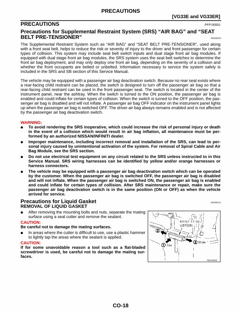
Precautions for Liquid Gasket EBS00EZO
REMOVAL OF LIQUID GASKET● After removing the mounting bolts and nuts, separate the mating
surface using a seal cutter and remove the sealant. CAUTION:Be careful not to damage the mating surfaces.● In areas where the cutter is difficult to use, use a plastic hammer
to lightly tap the areas where the sealant is applied.CAUTION:If for some unavoidable reason a tool such as a flat-bladedscrewdriver is used, be careful not to damage the mating sur-faces.
PBIC0002E
PRECAUTIONS
CO-19
[VG33E and VG33ER]
C
D
E
F
G
H
I
J
K
L
M
A
CO
Precautions for Liquid Gasket EBS00EZV
REMOVAL OF LIQUID GASKET● After removing the mounting bolts and nuts, separate the mating
surface using a seal cutter and remove the sealant. CAUTION:Be careful not to damage the mating surfaces.● In areas where the cutter is difficult to use, use a plastic hammer
to lightly tap the areas where the sealant is applied.CAUTION:If for some unavoidable reason a tool such as a flat-bladedscrewdriver is used, be careful not to damage the mating sur-faces.
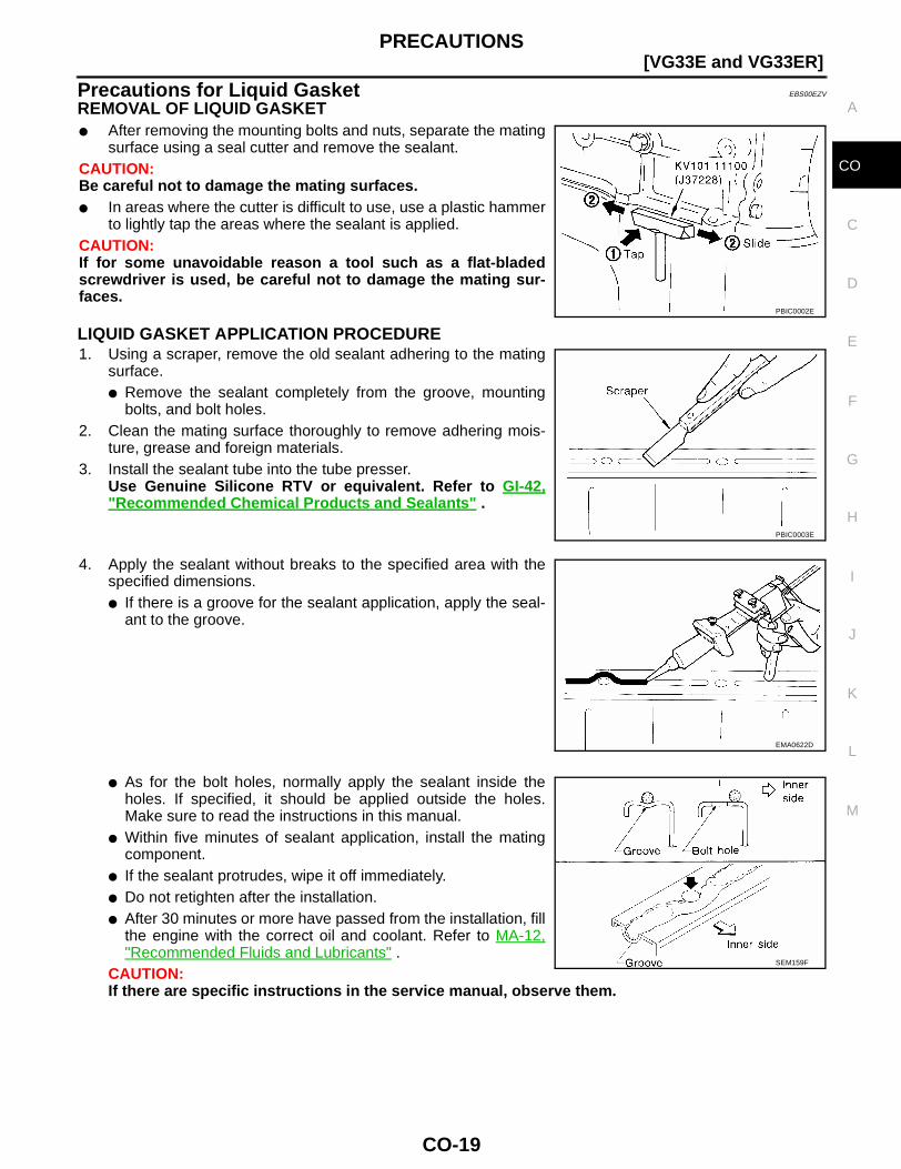
LIQUID GASKET APPLICATION PROCEDURE1. Using a scraper, remove the old sealant adhering to the mating
surface.● Remove the sealant completely from the groove, mounting
bolts, and bolt holes.2. Clean the mating surface thoroughly to remove adhering mois-
ture, grease and foreign materials.3. Install the sealant tube into the tube presser.
Use Genuine Silicone RTV or equivalent. Refer to GI-42,"Recommended Chemical Products and Sealants" .
4. Apply the sealant without breaks to the specified area with thespecified dimensions.● If there is a groove for the sealant application, apply the seal-
ant to the groove.
● As for the bolt holes, normally apply the sealant inside theholes. If specified, it should be applied outside the holes.Make sure to read the instructions in this manual.
● Within five minutes of sealant application, install the matingcomponent.
● If the sealant protrudes, wipe it off immediately.● Do not retighten after the installation.● After 30 minutes or more have passed from the installation, fill
the engine with the correct oil and coolant. Refer to MA-12,"Recommended Fluids and Lubricants" .
CAUTION:If there are specific instructions in the service manual, observe them.
PBIC0002E
PBIC0003E
EMA0622D
SEM159F
CO-20
[VG33E and VG33ER]PREPARATION
PREPARATION PFP:00002
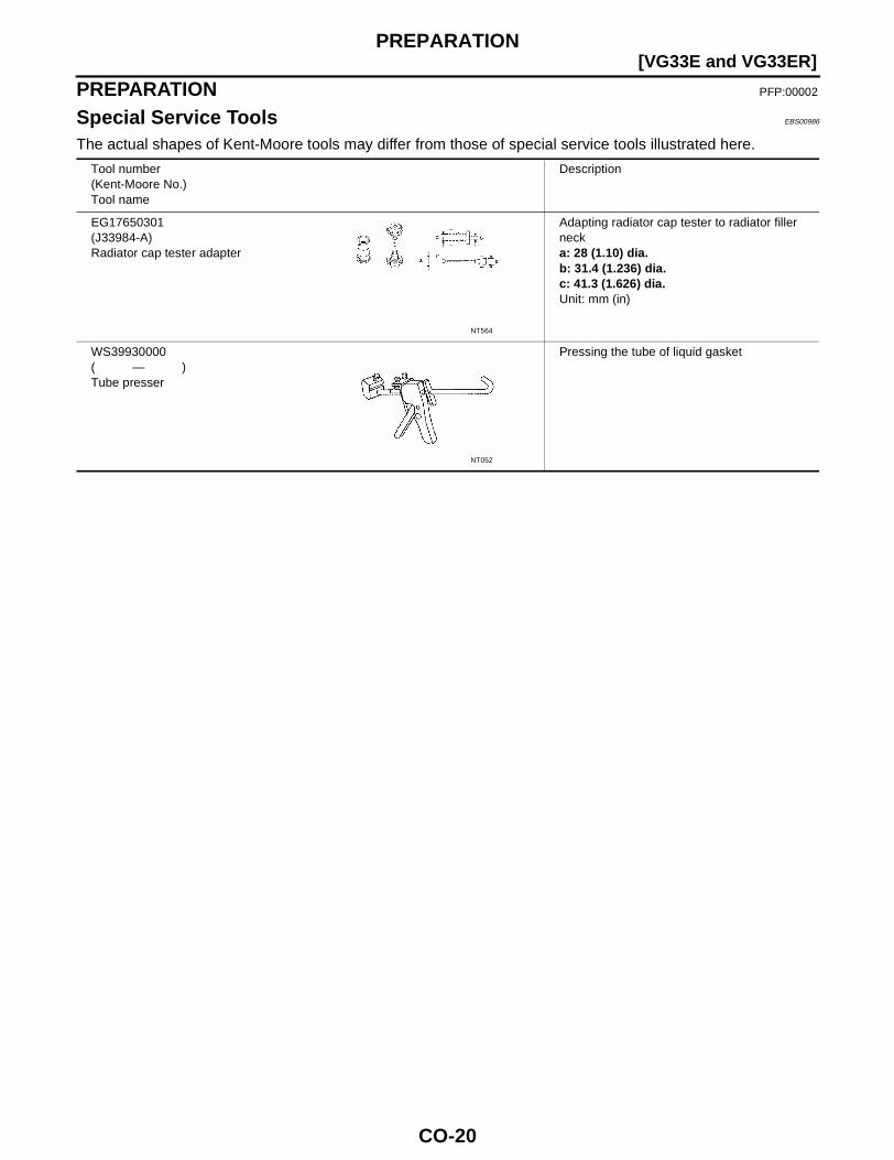
Special Service Tools EBS00986
The actual shapes of Kent-Moore tools may differ from those of special service tools illustrated here.
Tool number(Kent-Moore No.)Tool name
Description
EG17650301(J33984-A)Radiator cap tester adapter
Adapting radiator cap tester to radiator filler necka: 28 (1.10) dia.b: 31.4 (1.236) dia.c: 41.3 (1.626) dia.Unit: mm (in)
WS39930000( — )Tube presser
Pressing the tube of liquid gasket
NT564
NT052
OVERHEATING CAUSE ANALYSIS
CO-21
[VG33E and VG33ER]
C
D
E
F
G
H
I
J
K
L
M
A
CO
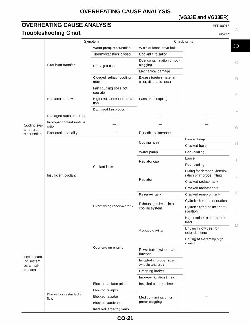
OVERHEATING CAUSE ANALYSIS PFP:00012
Troubleshooting Chart EBS00GJF
Symptom Check items
Cooling sys-tem parts malfunction
Poor heat transfer
Water pump malfunction Worn or loose drive belt
—
Thermostat stuck closed Coolant circulation
Damaged fins
Dust contamination or rock clogging
Mechanical damage
Clogged radiator cooling tube
Excess foreign material (rust, dirt, sand, etc.)
Reduced air flow
Fan coupling does not operate
Fans and coupling —High resistance to fan rota-tion
Damaged fan blades
Damaged radiator shroud — — —
Improper coolant mixture ratio
— — —
Poor coolant quality — Periodic maintenance —
Insufficient coolant
Coolant leaks
Cooling hoseLoose clamp
Cracked hose
Water pump Poor sealing
Radiator capLoose
Poor sealing
Radiator
O-ring for damage, deterio-ration or improper fitting
Cracked radiator tank
Cracked radiator core
Reservoir tank Cracked reservoir tank
Overflowing reservoir tankExhaust gas leaks into cooling system
Cylinder head deterioration
Cylinder head gasket dete-rioration
Except cool-ing system parts mal-function
— Overload on engine
Abusive driving
High engine rpm under no load
Driving in low gear for extended time
Driving at extremely high speed
Powertrain system mal-function
—Installed improper size wheels and tires
Dragging brakes
Improper ignition timing
Blocked or restricted air flow
Blocked radiator grille Installed car brassiere
—Mud contamination or paper clogging
Blocked bumper
Blocked radiator
Blocked condenser
Installed large fog lamp
CO-22
[VG33E and VG33ER]COOLING SYSTEM
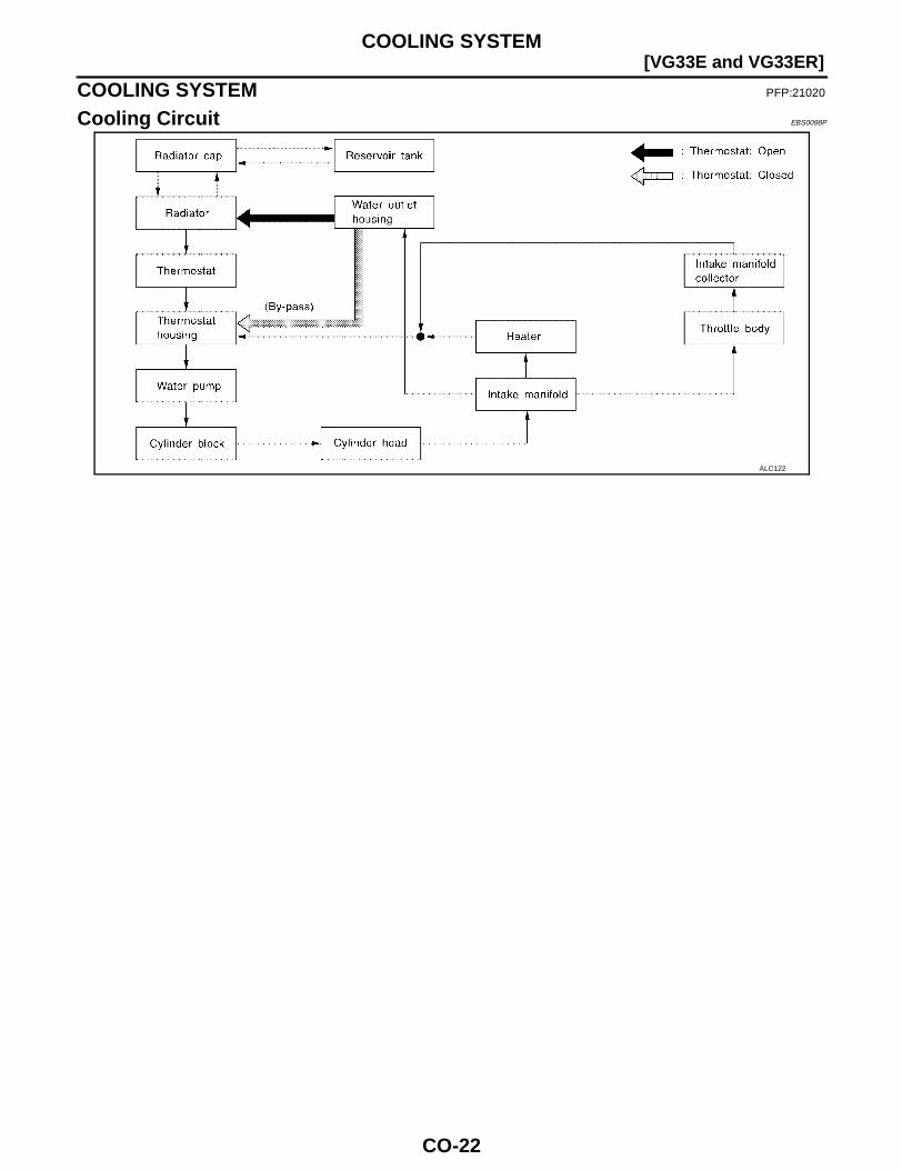
COOLING SYSTEM PFP:21020
Cooling Circuit EBS0098P
ALC122
ENGINE COOLANT
CO-23
[VG33E and VG33ER]
C
D
E
F
G
H
I
J
K
L
M
A
CO
ENGINE COOLANT PFP:KQ100
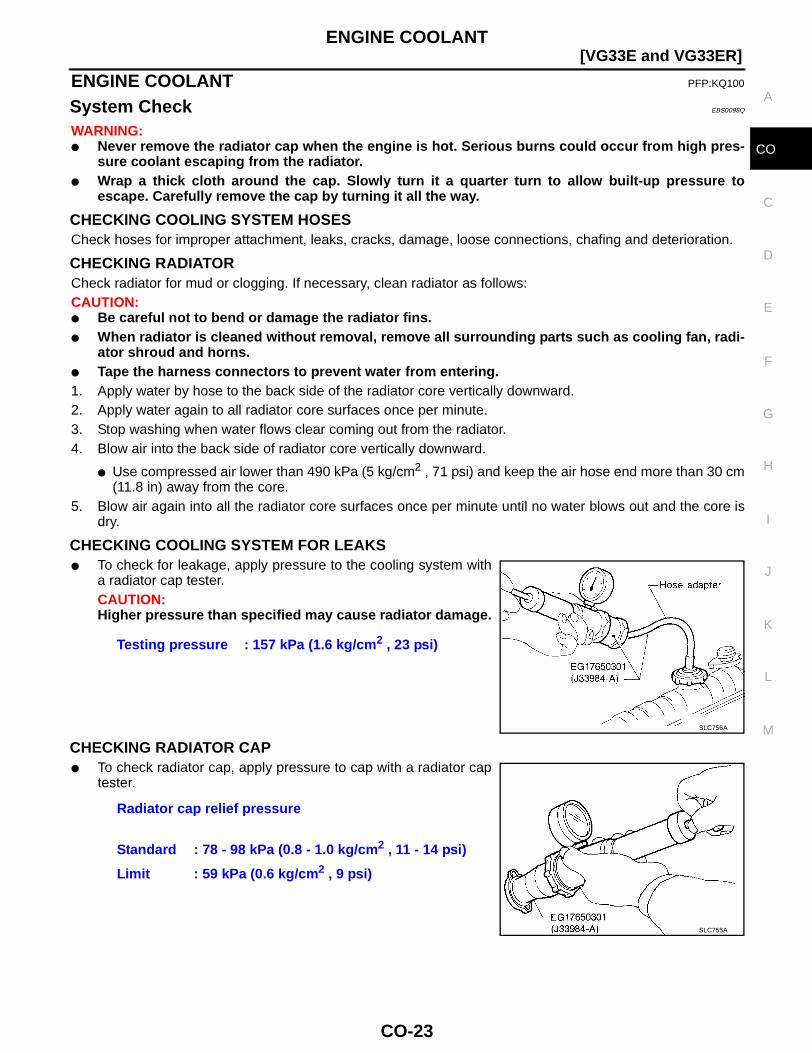
System Check EBS0098Q
WARNING:● Never remove the radiator cap when the engine is hot. Serious burns could occur from high pres-
sure coolant escaping from the radiator.● Wrap a thick cloth around the cap. Slowly turn it a quarter turn to allow built-up pressure to
escape. Carefully remove the cap by turning it all the way.
CHECKING COOLING SYSTEM HOSESCheck hoses for improper attachment, leaks, cracks, damage, loose connections, chafing and deterioration.
CHECKING RADIATORCheck radiator for mud or clogging. If necessary, clean radiator as follows:CAUTION:● Be careful not to bend or damage the radiator fins.● When radiator is cleaned without removal, remove all surrounding parts such as cooling fan, radi-
ator shroud and horns.● Tape the harness connectors to prevent water from entering.1. Apply water by hose to the back side of the radiator core vertically downward.2. Apply water again to all radiator core surfaces once per minute.3. Stop washing when water flows clear coming out from the radiator.4. Blow air into the back side of radiator core vertically downward.
● Use compressed air lower than 490 kPa (5 kg/cm2 , 71 psi) and keep the air hose end more than 30 cm(11.8 in) away from the core.
5. Blow air again into all the radiator core surfaces once per minute until no water blows out and the core isdry.
CHECKING COOLING SYSTEM FOR LEAKS● To check for leakage, apply pressure to the cooling system with
a radiator cap tester.CAUTION:Higher pressure than specified may cause radiator damage.
CHECKING RADIATOR CAP● To check radiator cap, apply pressure to cap with a radiator cap
tester.
Testing pressure : 157 kPa (1.6 kg/cm2 , 23 psi)
SLC756A
Radiator cap relief pressure
Standard : 78 - 98 kPa (0.8 - 1.0 kg/cm2 , 11 - 14 psi)
Limit : 59 kPa (0.6 kg/cm2 , 9 psi)
SLC755A
CO-24
[VG33E and VG33ER]ENGINE COOLANT
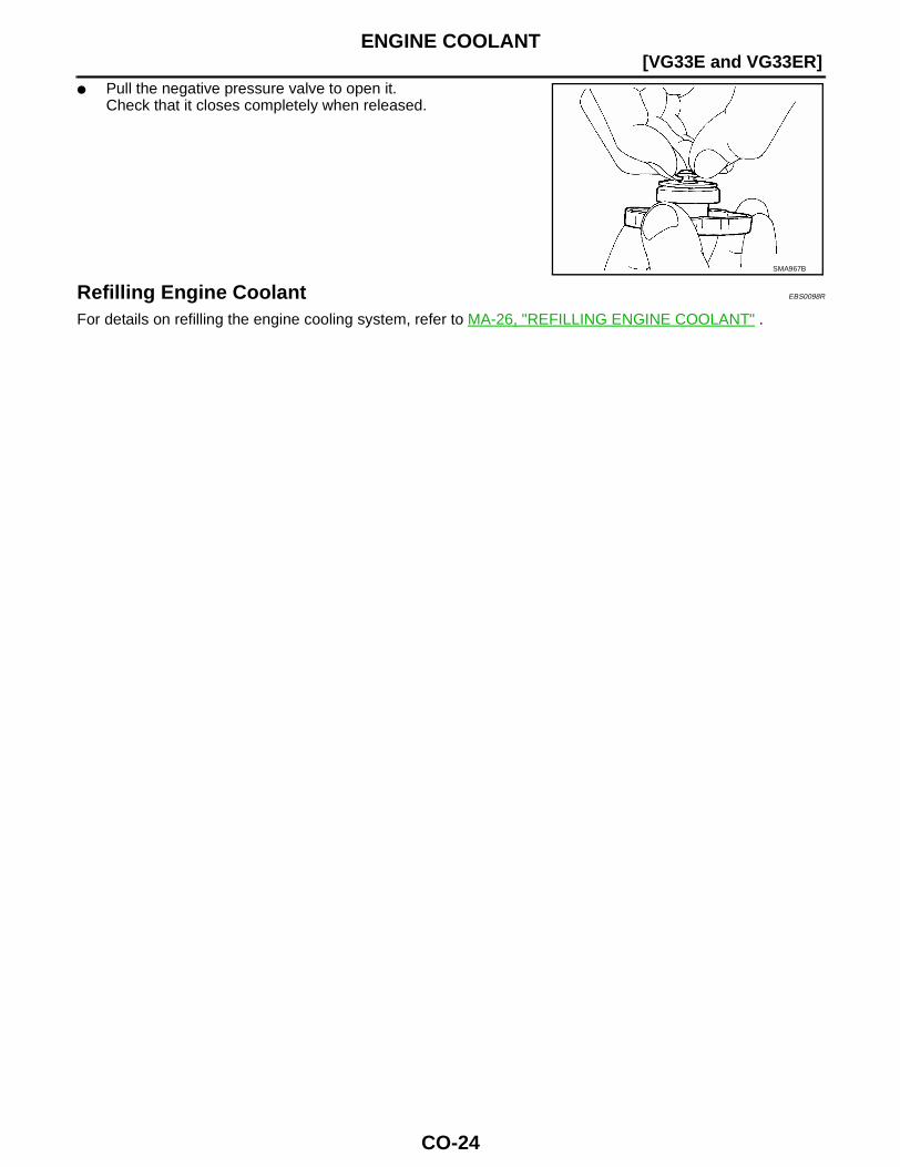
● Pull the negative pressure valve to open it.Check that it closes completely when released.
Refilling Engine Coolant EBS0098R
For details on refilling the engine cooling system, refer to MA-26, "REFILLING ENGINE COOLANT" .
SMA967B
WATER PUMP
CO-25
[VG33E and VG33ER]
C
D
E
F
G
H
I
J
K
L
M
A
CO
WATER PUMP PFP:21020
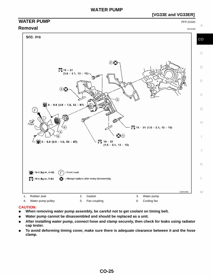
Removal EBS00989
CAUTION:● When removing water pump assembly, be careful not to get coolant on timing belt.● Water pump cannot be disassembled and should be replaced as a unit.● After installing water pump, connect hose and clamp securely, then check for leaks using radiator
cap tester.● To avoid deforming timing cover, make sure there is adequate clearance between it and the hose
clamp.
1. Rubber seal 2. Gasket 3. Water pump
4. Water pump pulley 5. Fan coupling 6. Cooling fan
LBIA0328E
CO-26
[VG33E and VG33ER]WATER PUMP
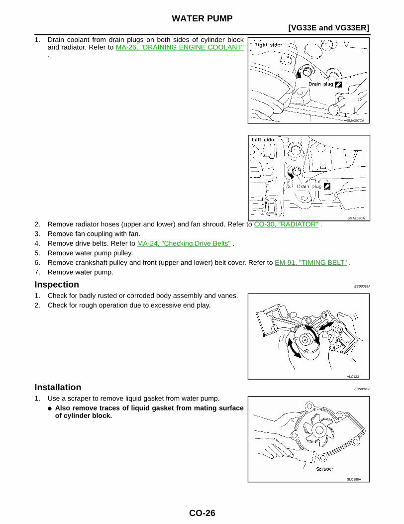
1. Drain coolant from drain plugs on both sides of cylinder blockand radiator. Refer to MA-26, "DRAINING ENGINE COOLANT".
2. Remove radiator hoses (upper and lower) and fan shroud. Refer to CO-30, "RADIATOR" .3. Remove fan coupling with fan.4. Remove drive belts. Refer to MA-24, "Checking Drive Belts" .5. Remove water pump pulley.6. Remove crankshaft pulley and front (upper and lower) belt cover. Refer to EM-91, "TIMING BELT" .7. Remove water pump.
Inspection EBS0098A
1. Check for badly rusted or corroded body assembly and vanes.2. Check for rough operation due to excessive end play.
Installation EBS0098B
1. Use a scraper to remove liquid gasket from water pump.● Also remove traces of liquid gasket from mating surface
of cylinder block.
SMA207CA
SMA208CA
ALC123
SLC188A
WATER PUMP
CO-27
[VG33E and VG33ER]
C
D
E
F
G
H
I
J
K
L
M
A
CO
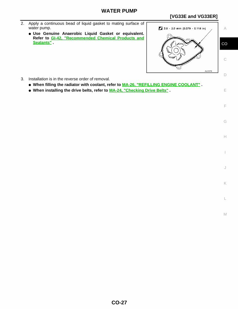
2. Apply a continuous bead of liquid gasket to mating surface ofwater pump.● Use Genuine Anaerobic Liquid Gasket or equivalent.
Refer to GI-42, "Recommended Chemical Products andSealants" .
3. Installation is in the reverse order of removal.● When filling the radiator with coolant, refer to MA-26, "REFILLING ENGINE COOLANT" .● When installing the drive belts, refer to MA-24, "Checking Drive Belts" .
ALC078
CO-28
[VG33E and VG33ER]THERMOSTAT
THERMOSTAT PFP:21200
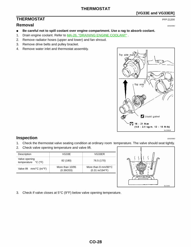
Removal EBS0098C
● Be careful not to spill coolant over engine compartment. Use a rag to absorb coolant.1. Drain engine coolant. Refer to MA-26, "DRAINING ENGINE COOLANT" .2. Remove radiator hoses (upper and lower) and fan shroud.3. Remove drive belts and pulley bracket.4. Remove water inlet and thermostat assembly.
Inspection EBS0098D
1. Check the thermostat valve seating condition at ordinary room temperature. The valve should seat tightly.2. Check valve opening temperature and valve lift.
3. Check if valve closes at 5°C (9°F) below valve opening temperature.
SLC081B
Description VG33E VG33ER
Valve opening temperature °C (°F)
82 (180) 76.5 (170)
Valve lift mm/°C (in/°F)More than 10/95
(0.39/203)More than 8 mm/90°C
(0.31 in/194°F)
SLC343
THERMOSTAT
CO-29
[VG33E and VG33ER]
C
D
E
F
G
H
I
J
K
L
M
A
CO
Installation EBS0098E
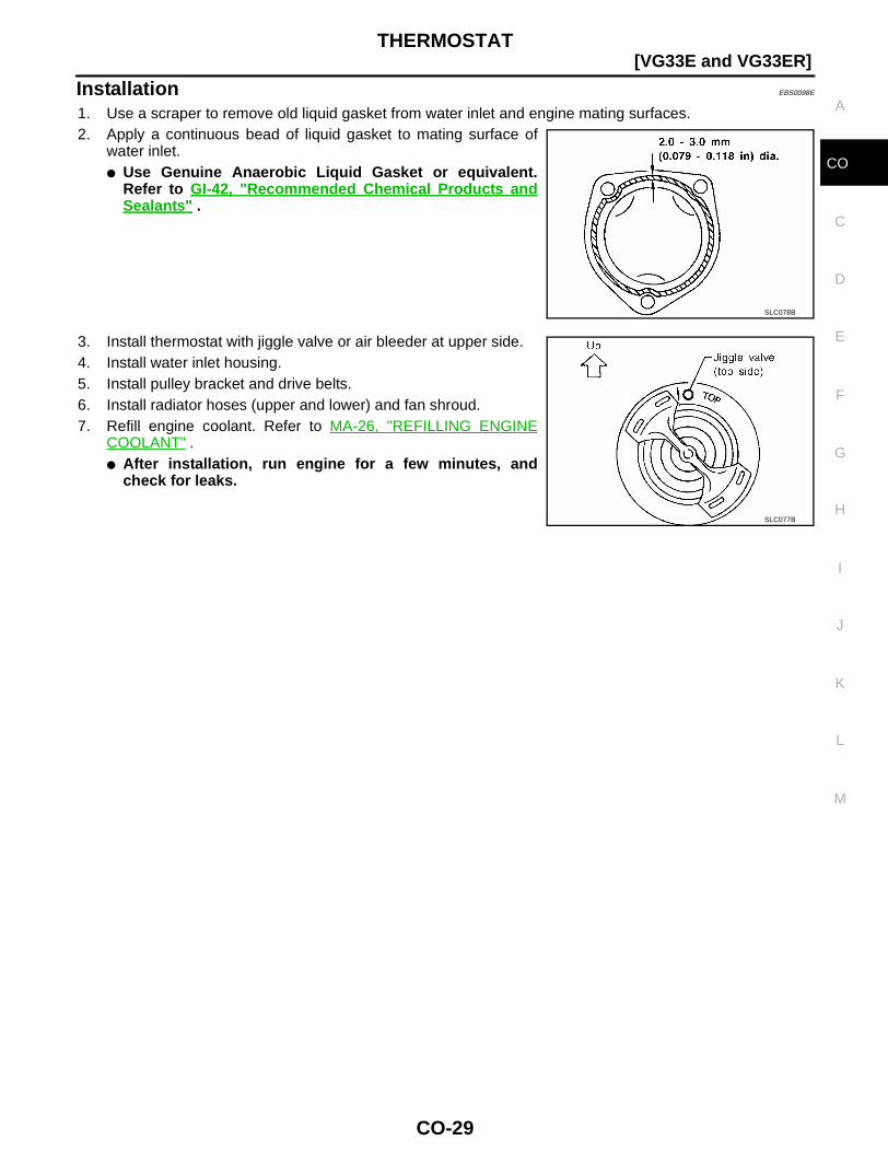
1. Use a scraper to remove old liquid gasket from water inlet and engine mating surfaces.2. Apply a continuous bead of liquid gasket to mating surface of
water inlet.● Use Genuine Anaerobic Liquid Gasket or equivalent.
Refer to GI-42, "Recommended Chemical Products andSealants" .
3. Install thermostat with jiggle valve or air bleeder at upper side.4. Install water inlet housing.5. Install pulley bracket and drive belts.6. Install radiator hoses (upper and lower) and fan shroud.7. Refill engine coolant. Refer to MA-26, "REFILLING ENGINE
COOLANT" .● After installation, run engine for a few minutes, and
check for leaks.
SLC078B
SLC077B
CO-30
[VG33E and VG33ER]RADIATOR
RADIATOR PFP:21400
Components EBS0098G
Removal and Installation EBS0098F
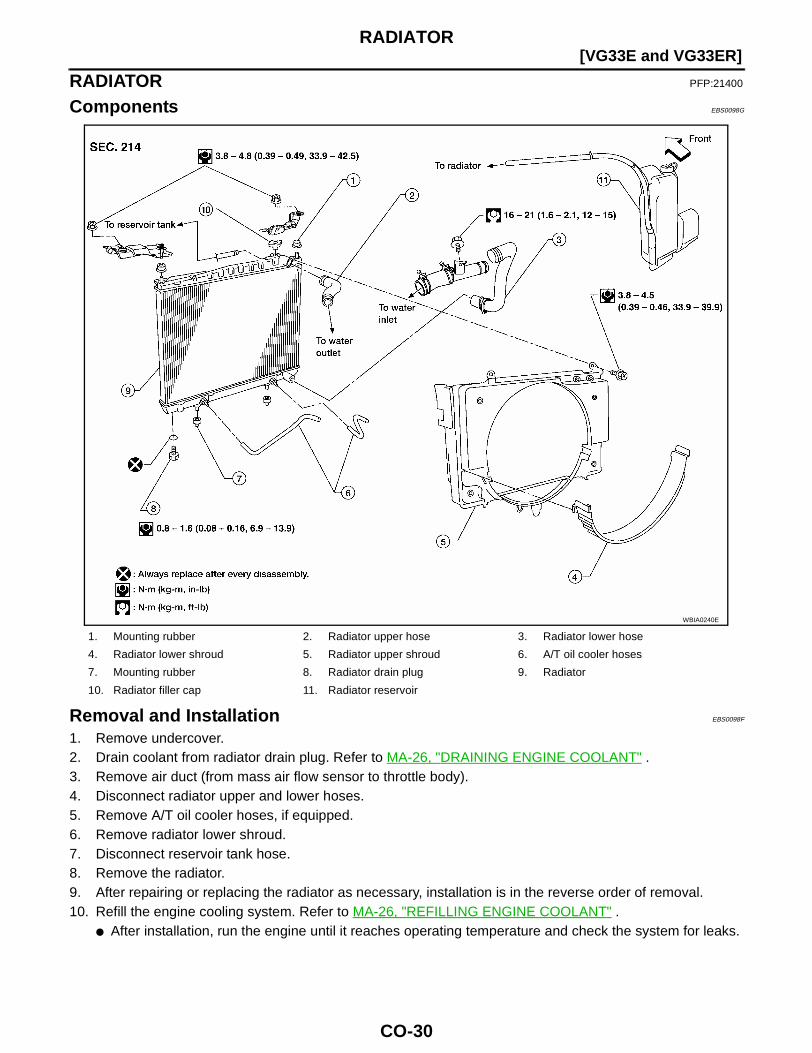
1. Remove undercover.2. Drain coolant from radiator drain plug. Refer to MA-26, "DRAINING ENGINE COOLANT" .3. Remove air duct (from mass air flow sensor to throttle body).4. Disconnect radiator upper and lower hoses.5. Remove A/T oil cooler hoses, if equipped.6. Remove radiator lower shroud.7. Disconnect reservoir tank hose.8. Remove the radiator.9. After repairing or replacing the radiator as necessary, installation is in the reverse order of removal.10. Refill the engine cooling system. Refer to MA-26, "REFILLING ENGINE COOLANT" .
● After installation, run the engine until it reaches operating temperature and check the system for leaks.
1. Mounting rubber 2. Radiator upper hose 3. Radiator lower hose
4. Radiator lower shroud 5. Radiator upper shroud 6. A/T oil cooler hoses
7. Mounting rubber 8. Radiator drain plug 9. Radiator
10. Radiator filler cap 11. Radiator reservoir
WBIA0240E
RADIATOR
CO-31
[VG33E and VG33ER]
C
D
E
F
G
H
I
J
K
L
M
A
CO
Inspection EBS0098H
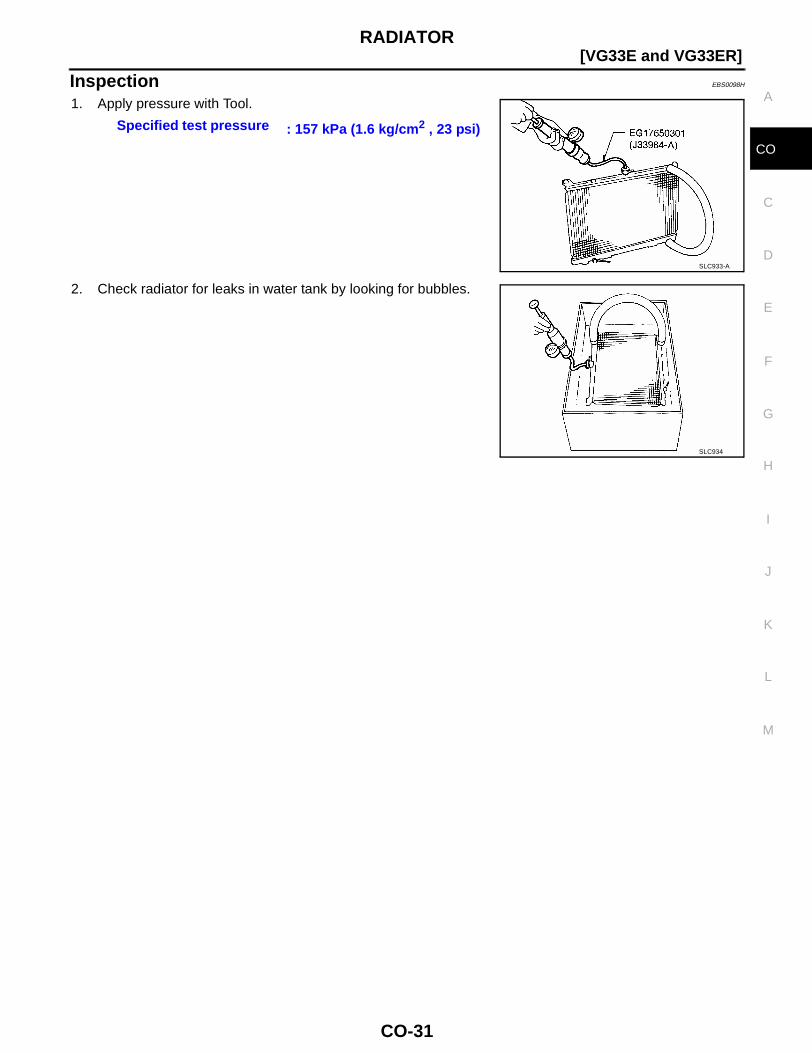
1. Apply pressure with Tool.
2. Check radiator for leaks in water tank by looking for bubbles.
Specified test pressure : 157 kPa (1.6 kg/cm2 , 23 psi)
SLC933-A
SLC934
CO-32
[VG33E and VG33ER]COOLING FAN (CRANKSHAFT DRIVEN)
COOLING FAN (CRANKSHAFT DRIVEN) PFP:21060
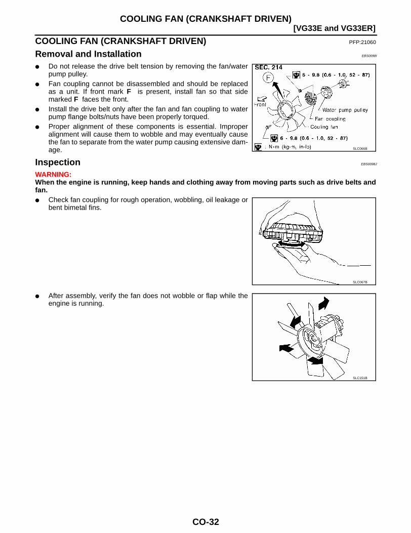
Removal and Installation EBS0098I
● Do not release the drive belt tension by removing the fan/waterpump pulley.
● Fan coupling cannot be disassembled and should be replacedas a unit. If front mark F is present, install fan so that sidemarked F faces the front.
● Install the drive belt only after the fan and fan coupling to waterpump flange bolts/nuts have been properly torqued.
● Proper alignment of these components is essential. Improperalignment will cause them to wobble and may eventually causethe fan to separate from the water pump causing extensive dam-age.
Inspection EBS0098J
WARNING:When the engine is running, keep hands and clothing away from moving parts such as drive belts andfan.● Check fan coupling for rough operation, wobbling, oil leakage or
bent bimetal fins.
● After assembly, verify the fan does not wobble or flap while theengine is running.
SLC066B
SLC067B
SLC151B
SERVICE DATA AND SPECIFICATIONS (SDS)
CO-33
[VG33E and VG33ER]
C
D
E
F
G
H
I
J
K
L
M
A
CO
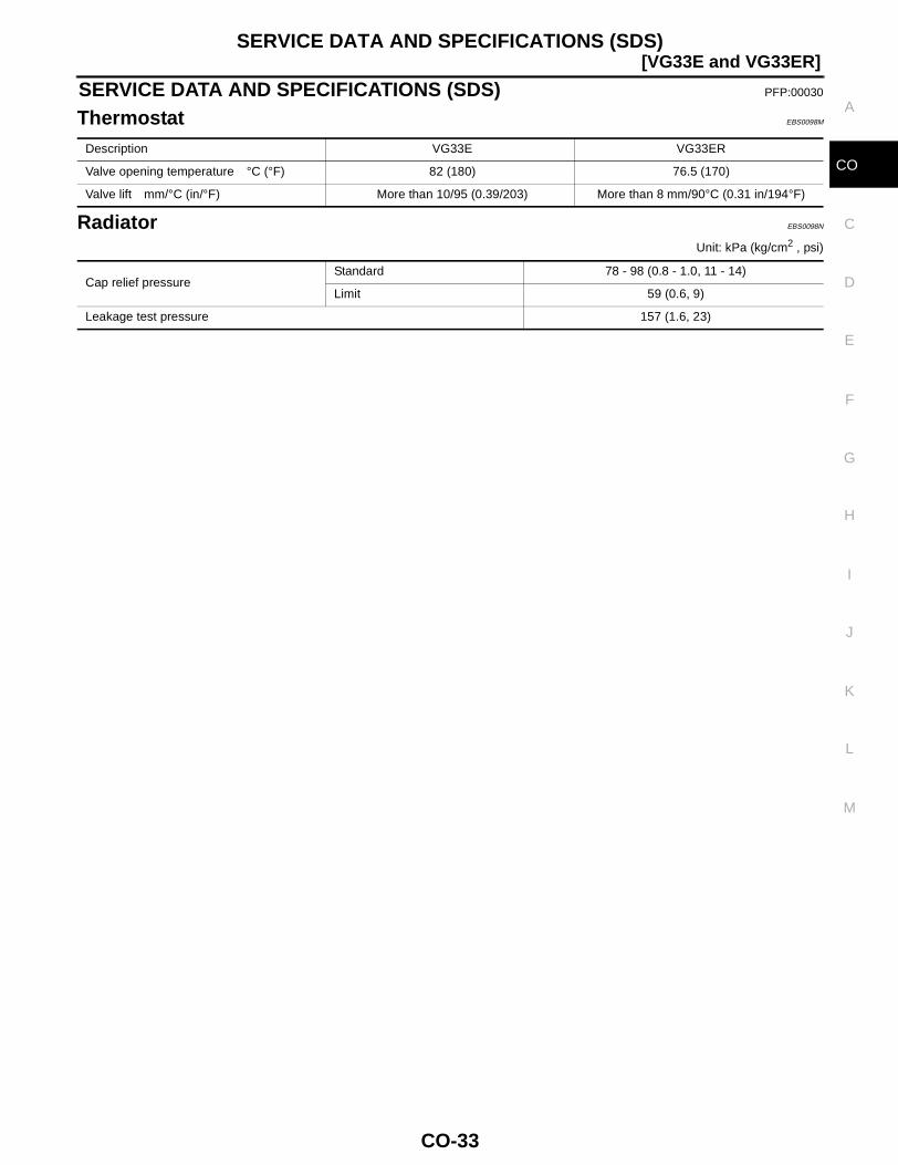
SERVICE DATA AND SPECIFICATIONS (SDS) PFP:00030
Thermostat EBS0098M
Radiator EBS0098N
Unit: kPa (kg/cm2 , psi)
Description VG33E VG33ER
Valve opening temperature °C (°F) 82 (180) 76.5 (170)
Valve lift mm/°C (in/°F) More than 10/95 (0.39/203) More than 8 mm/90°C (0.31 in/194°F)
Cap relief pressureStandard 78 - 98 (0.8 - 1.0, 11 - 14)
Limit 59 (0.6, 9)
Leakage test pressure 157 (1.6, 23)
CO-34
[VG33E and VG33ER]SERVICE DATA AND SPECIFICATIONS (SDS)