Embed Size (px)
Citation preview

Master Plan Update January 3, 2008
Campbell & Paris Engineers (Project #0209-8) Page 3-1
SECTION THREE FACILITY REQUIREMENTS
Each component of the Virginia Tech-Montgomery Executive Airport has been evaluated for its ability to accommodate the forecasted demand for general aviation facilities and services. This includes evaluating the airport’s ability to meet the design and safety standards as established by the FAA in AC 150/5300-13 “Airport Design” and FAR Part 77 “Objects Affecting Navigable Airspace”. The results are described in this chapter and provide the basis for determining what additional facilities or improvements are required. Facility requirements for each component are described and correspond to the short-range (five-year), mid-range (ten year), and long range (20 year) planning horizons. Some long term needs are presented in concept, recognizing that when demands reach the levels requiring these facilities, additional detailed planning may be required. The recommended development strategy will be presented in Section Four along with a brief evaluation of alternative development scenarios. This Section addresses the following:
1. Runway Length Analysis 2. Relocation of Tech Center Drive 3. Parallel Taxiway Location 4. Hangar Requirements 5. Terminal Area Layout/Location 6. Based and Transient Aircraft Apron Size 7. Obstruction Analysis/Approach Capability 8. Land Acquisition
Based aircraft are forecasted to grow from 36 to 49 aircraft, and annual Baseline operations from 16,033 to 26,425 over a 20 year period, with an additional 750 annual operations related to University events. This level of growth is significant; however, demand is more than likely to increase beyond this moderate growth rate if adequate and affordable facilities are provided. The historical growth of the airport may have been constrained due to lack of facilities (i.e. hangars and the runway length). A key purpose of this Master Plan Update is to identify a general layout for future facilities to support the safe and efficient operation of the airport, while providing the Authority flexibility to meeting both anticipated and unforeseen demands. For these reasons, the facility requirements identified by this Master Plan Update will be based on complying with standards, improving the utility of the facilities and the accommodating operational characteristics of the aircraft anticipated to use the airport.

Master Plan Update January 3, 2008
Campbell & Paris Engineers (Project #0209-8) Page 3-2
3.1 AIRPORT REFERENCE CODE & “CRITICAL AIRCRAFT” Airport planning begins with the determination of the appropriate FAA design criteria. These criteria establish basic design considerations for building restriction lines, setbacks, obstacle clearance requirements, runway protection zones, etc., necessary to accommodate the most "critical aircraft" or aircraft types expected to use the facility over the planning horizon. FAA Advisory Circular 150/5300-13, "Airport Design," identifies these development criteria on the basis of aircraft size, weight, approach speed, and other operational characteristics (ARC: Airport Reference Code). Refer to Figure 1-21: Airport Reference Code Designations, to review the various aircraft codes and meanings.
This airport is currently a B-II and the existing critical aircraft is the Falcon 900. The previous Master Plan provided planning for Virginia Tech-Montgomery Executive Airport to accommodate C-II type aircraft and the 2003 VATSP identifies this airfield as a C-II. The future critical aircraft family that this airfield is to be designed for is C-II, which includes corporate aircraft such as the Cessna X, CL 600, and Gulfstream 350. The 2005 operations by turbo-prop and jet aircraft, the anticipated tenant base, and the operational forecasts recommended by this report, support the continued development of this airfield to accommodate a variety of general aviation aircraft with a focus on the C-II ARC. This is consistent with 2003 VATSP and is highly reasonable, considering the national aviation trends and the Authority goal to be an economic development tool for the region. The critical aircraft family, C-II, includes a wide variety of aircraft that can typically accommodate 20 or more passengers, have ranges of 3,000-4,500 miles and would be the common type of aircraft operated by businesses (or fractional operators). Some of the typical business aircraft that utilize or are expected to utilize the airfield are identified in Figure 3-1.

Master Plan Update January 3, 2008
Campbell & Paris Engineers (Project #0209-8) Page 3-3
FIGURE 3-1 Typical ARC B-II & C-II Business Use Aircraft
A R C
Manufacturer Model Wingspan (ft) MTOW (lbs) Seats Range (mi) w/ 45 min reserve
FAA T/O Field Length - ISO (ft)
Challenger 600,601,604
64.3 41,250 - 47,600
9-19 3,300-4,900 5,400-6,050
Bombardier Continental 63.8 37,650 8-16 3,915 4,950
Cessna Citation 525A (CJ-2), 550, 551 , 552, S550,560
51.7 - 55.7 12,500 - 20,000
5-10 1,700-2,400 2,650-3,600
Dassault Falcon 20, 50,900,2000
53.5 - 63.4 28,660 - 45,500
8-19 3,900-4,900 4,900-5,500
Hawker 800, Horizon
51.4 - 61.8 28,00 - 36,000 8-12 3,400-4,400 5,000-5,250
B-II
Raytheon King Air C90,B200,350
50.3 - 57.9 10,100 - 15,000
6-16 1,600-2,400 2,500-3,300
Canadair CL-600 61 40,400 14-20 3,400 5,840
Grumman Gulfstream 350 77 69,700 9-21 3,800 5,050
Lockheed Jetstar 54.3 48,940 10 2,600
Rockwell Sabre 80 50.5 23,000 10 1,713 4,460
C-II
Cessna X 63 37,000 8-14 3,200 5,140
Sources: Aviation Week & Space Technology-1/13/2003, Jane’s Aircraft of the World, FAA AC150/5300-13, Classic FAA planning criteria indicates that the determination of a critical aircraft or critical aircraft type is based on a threshold of 500 estimated annual operations. The FAA also uses this for funding assistance on development projects that are intended to support operations by those aircraft. The forecasts described in Section Two were developed using an operations-per-based-aircraft methodology and stated that Virginia Tech-Montgomery Executive Airport will experience an increase of between 1,000 and 2,700 annual jet operations over the course of the planning horizon. It should also be noted that the Jet operation forecast of 1,061included in Figure 2-19 for 2005 primarily include B-II type aircraft, such as the Falcon 50 and Cessna Citation, however based on observations approximate 100-150 operations per year are preformed by C-II type aircraft. If the runway is extended

Master Plan Update January 3, 2008
Campbell & Paris Engineers (Project #0209-8) Page 3-4
the forecasted growth in jet operations will include operations by larger more demanding aircraft and as such a higher percentage of jet operations by C-II type aircraft. Over the planning horizon business aircraft that are faster and more sophisticated will be based at the airfield by corporations located in the Corporate Research Center (CRC) or nearby Industrial Parks, if facilities are available. These aircraft are anticipated to be similar to the Gulfstream 350, Canadair 600, and Cessna X. It is also reasonable to assume that as the economy and business community of the region continues to grow, and the services and facilities at BCB continue to improve, the size and complexity of aircraft operating into the airport may increase. Planning for the heavier and faster C-II aircraft would allow the airport to regularly accommodate the wide range of aircraft used by most corporate groups. When evaluating or justifying facility projects, it is important to consider the lifespan of the proposed improvement as it relates to both existing traffic demands and what is anticipated in the future. For example, when designing new or rehabilitated pavements (i.e. load bearing capacity, fillet dimensions, geometry), consideration must be given to the anticipated long range critical aircraft, as well as acknowledged or common operations by aircraft that may be larger than the designated critical planning aircraft (based on the 500 annual operations guideline). The 100 foot wide runway is capable of handling the Group III aircraft that can utilize the existing runway length, and as such BCB should expect occasional use from Group III aircraft. Additionally, different facilities within the airport may be developed to specifically accommodate different aircraft types. For example, the main transient apron would be designed to accommodate Group-II aircraft while the t-hangar taxilanes would more than likely be designed to accommodate only Group-I aircraft. 3.2 INSTRUMENT APPROACH CAPABILITY As of January 2006, the airfield has three published approach plates with seven procedures, see Figure 1-26. These include circling and straight-in approaches to Runway 12 from the west. When compared to the other airports in the area (PSK and ROA), the approaches available are less sophisticated than at the two nearby airports, which provide ILS approaches. Section Two states that national aviation trends show increasing demand for instrument flight rule (IFR) capability. This is a direct result of the increased use of business type aircraft that must be ready to fly in all types of weather and rely on GA facilities with adequate instrument approach capabilities. Business aircraft operators also typically fly the more sophisticated aircraft and have pilots with advanced ratings. Correspondingly the FAA has forecasted the fastest growth in pilot licensing for Commercial (1.2% annually), Airline Transport (1.9% annually) and pilots with instrument ratings (1.2% annually) 8. With 8FAA Aerospace Forecasts 2003-2014

Master Plan Update January 3, 2008
Campbell & Paris Engineers (Project #0209-8) Page 3-5
general aviation accounting for almost 40 percent of the recorded instrument operations and the ongoing improvements to satellite based navigation systems, it is only logical for BCB to continue improving the facilities to provide the best instrument approach capability possible. Consistent with the 2003 VATSP, the airfield should strive to achieve the best possible minimums for both Runway 12 and Runway 30 approaches. Instrument Approach improvements will increase the utility of the airfield for the business aviation community and increase the level of safety for all pilots as well as the neighboring community during all weather conditions. Maintaining non-precision approach capability with visibility minimums of 1-mile or greater, is consistent with the other airports in the general area and the airspace system demands described in the VATSP. While providing precision instrument approach capability (i.e. ILS) may be desired, or required, by some aircraft operators the cost and benefit of providing ILS must be considered. It should also be noted that the availability of affordable well maintained hangar facilities and an attractive marketing/incentive program by the airport could increase the demand for improved approaches. This Master Plan Update will utilize planning criteria associated with non-precision instrument approaches and1-mile visibility minimums to both ends of Runway 12/30. 3.3 AIRPORT DESIGN STANDARDS The design standards for three airport development scenarios have been identified and compared to the existing conditions. These different scenarios include 1) improving the existing facility to meet the C-II standards, 2) comparing the geometric design standards needed to accommodate Category-D aircraft, 3) improving the approach minimums to ≥¾ mile and in order to investigate the feasibility of providing a precision approach. These different scenarios have been included to demonstrate the space demands that would need to be placed on the airport to achieve these capabilities. Figure 3-2 provides the comparison between the existing facility and the improvements needed to meet C-II standards. There is a concern that 800’ of the existing parallel taxiway has a 240’ separation from the runway centerline. This 240’ separation does not meet the standard 300’ separation needed for Group II aircraft. In addition do to its pavement strength; this eastern end of the taxiway is only able to be utilized by aircraft weighting less than 12,500lbs. Heavier corporate aircraft need to back-taxi 800’ down the runway to utilize the entire runway length.

Master Plan Update January 3, 2008
Campbell & Paris Engineers (Project #0209-8) Page 3-6
FIGURE 3-2 Existing Condition vs. C-II Airfield Standards
RED TEXT = Below C-II Standard
BLUE TEXT = Above B-II Standard
EXISTING CONDITION C-II STANDARDS
Aircraft approach category Airplane design group Airplane wingspan Maximum certificated takeoff weight Critical aircraft
B II
78.99 feet 45,500 lbs B-II Class
C II
78.99 feet 45,500 lbs C-II Class
RW 12 Approach Type Visibility Minimums Approach Slope RW 30 Approach Type Visibility Minimums Approach Slope
non-precision ≥1 mile
34:1
non-precision ≥1 mile
34:1
non-precision ≥1 mile
34:1
non-precision ≥1 mile
34:1
Runway width 100 feet 100 feet
Runway shoulder width 10 feet 10 feet
Runway safety area width 150 feet 500 feet
Runway safety area length beyond each runway or stopway end, whichever is greater
300 feet 1000 feet
Runway object free (OFA) area width 800 feet 800 feet
Runway OFA length beyond each runway end or stopway end, whichever is greater
300 feet
1000 feet
Runway centerline to parallel taxiway and taxilane centerline
300 feet majority 240 feet eastern end
300 feet
Runway centerline to edge of aircraft parking 400 feet 400 feet
Runway protection zone at Length Width 200 feet from runway end Width @ far end of RPZ
(Runway 12) 1000 feet 500 feet 700 feet
(Runway 12) 1700 feet 500 feet
1010 feet

Master Plan Update January 3, 2008
Campbell & Paris Engineers (Project #0209-8) Page 3-7
RUNWAY 12/30
RED TEXT = below standard BLUE TEXT = above standard
EXISTING CONDITIONS C-II AIRFIELD STANDARDS
Runway protection zone: Length Width 200 feet from runway end Width @ far end of RPZ
(Runway 30) 1000 feet 500 feet 700 feet
(Runway 30) 1700 feet 500 feet
1010 feet
Runway obstacle free zone (OFZ) width 400 feet 400 feet Runway OFZ length beyond the runway end 200 feet 200 feet
Inner-Approach OFZ width (applicable only with ALS)
400 feet 400 feet
Inner-Approach OFZ length beyond approach light system (applicable only with ALS)
200 feet 200 feet
Inner-Approach OFZ slope from 200 feet beyond threshold (applicable only with ALS)
50:1 50:1
Inner-Transitional OFZ slope N/A N/A
Taxiway width 35 feet 35 feet
Taxiway wingtip clearance 26 feet 26 feet
Taxiway Safety Area Width 79 feet 79 feet
Taxiway Object Free Area Width 131 feet 131 feet
Taxilane wingtip clearance N/A 18 feet
Taxilane Object Free Area 115 feet 115 feet
Taxiway centerline to parallel taxiway or taxilane centerline
N/A 105 feet
Taxilane centerline to parallel taxilane centerline
97 97 feet
Taxiway centerline to fixed/movable object 65.5 feet 65.5 feet
Master Plan Update January 3, 2008
Campbell & Paris Engineers (Project #0209-8) Page 3-8
As shown in Figure 3-2, for the airfield to meet C-II standards the Runway Safety Area and Object Free Area beyond the stopway end needs to be improved to 1000’. In addition, the eastern taxi-way that is located 240’ from the Runway centerline needs to be corrected or addressed to meet the 300’ separation distance. A comparison of C-II and D-II airfield standards is provided simply as information and, as stated in Section 3.2, the long range critical aircraft family is planned to be C-II. Similar to the C-II category, most D-II aircraft are corporate aircraft. In addition to having faster approach speeds for landing, most D-II aircraft are designed for longer ranged flights than their C-II counterparts. Most D-II aircraft require runways 5,100 – 5,500 feet for operation. For this airfield to accommodate D-II aircraft, the RSA width would be required to increase from 400 feet to 500 feet. In addition, pavement strength for the runways, taxiways, and aprons would need to be increased to accommodate these heavier aircraft. A typical D-II aircraft is the Gulfstream 450. Although the critical aircraft family for the airport will be C-II, if the runway is extended beyond 5,000 feet in length Virginia Tech Montgomery Executive Airport should expect to have occasional usage by D-II aircraft. 3.4 RUNWAY & TAXIWAY PLANNING FACTORS 3.4.1 Runway Configuration The existing orientation of Runway 12/30 is appropriate and meets the FAA standards for crosswind coverage, as shown in Section 1.5. As such the orientation of the runway is not recommended to change. Additionally crosswind improvements are not necessary or justified.
3.4.2 Runway Length Analysis The required runway length at any airport is a function of temperature, altitude, runway gradient, critical aircraft performance capabilities and weather conditions (i.e. wet or dry pavement and wind speed). Generally accepted FAA guidance is to provide sufficient runway length to accommodate 75% of the large aircraft group (based on representative aircraft within the national fleet mix) with up to a 60% useful payload. Analysis of the recommended runway length was performed using AC 150/5325-4B “Runway Length Requirements for Airport Design” and the FAA Airport Design Software v4.d. Based on the physical characteristics at BCB, including the normal maximum temperature of 82.60F (i.e. mean daily maximum temperature of the hottest month), an airport elevation of 2134 feet MSL, and a runway gradient change of 32 feet; a minimum runway length of 5,320 feet would be required (see Figure-3-4) in order to meet this basic criteria. This is consistent with the VATSP planning methodology that recommends airports with more than 500 annual jet operations have a runway length of at least 5,500 feet.

Master Plan Update January 3, 2008
Campbell & Paris Engineers (Project #0209-8) Page 3-9
FIGURE-3-3: FAA Runway Length Calculations Wet & Dry Pavement Conditions Mean daily maximum temperature of the hottest month
82.6° F
Runway Elevation 2,134 feet Maximum difference in runway centerline elevation
32 feet
Small airplanes with approach speeds of less than 30 knots
360 feet
Small airplanes with approach speeds of less than 50 knots 970 feet
Small airplanes with less than 10 passenger seats 75 percent of these small airplanes 95 percent of these small airplanes 100 percent of these small airplanes Small airplanes of 10 or more passenger seats
3,150 feet Dry and Wet 3,800 feet Dry and Wet 4,380 feet Dry and Wet 4,560 feet Dry and Wet
Large airplanes of 60,000 pounds or less 75 percent of these large airplanes at 60% useful load 75 percent of these large airplanes at 90% useful load 100 percent of these large airplanes at 60% useful load 100 percent of these large airplanes at 90% useful load
5,320 feet Dry (5,500 Wet) 6,900 feet Dry (7,000 Wet) 6,170 feet Dry (6,170 Wet) 8,840 feet Dry (8,840 Wet)
Source: AC 150/5300-13, Airport Design (chg. 6) and FAA Computer Program Airport Design v.4.2D Runway length information on typical C-II family aircraft, such as the Cessna X and CL 604 was also analyzed to better determine specific runway length requirements. The Cessna X’s performance information indicates a takeoff field length requirement at maximum take-off weight (sea level) is 5,140 feet and increases to a runway length of 5,890 feet when at an elevation of 5,000 feet (above sea level) and temperature of 77o at 75% useful load. Another C-II aircraft, the CL 604, has a performance curve chart which indicates at Blacksburg’s elevation (2,134 ft) at ISA conditions a need for 5,900ft of runway at 75% useful load. Based on this, it is apparent that the C-II family of aircraft has operational limitations with the existing 4,550 feet of available runway at BCB and a runway length of 5,500ft would meet the critical aircraft family’s operational requirements.

Master Plan Update January 3, 2008
Campbell & Paris Engineers (Project #0209-8) Page 3-10
Figure 3-4: Aircraft Specific Runway Length Calculations Airport Elevation 2,120’amsl Mean daily maximum temperature of the hottest month 82.6° F Headwind zero Flap Setting 20° Runway Gradient 0.6% Manufacturer Model FAA T/O
Field Length -ISO
@ MTOW @60%Useful Load
Useful Load w/ 5,500’
Cessna X 5,140’ 5,545’ 4,200’ 99% Gulfstream 350 5,050 6,650’ 5,200’ 71% Canadair 604 5,840 6,500’ 5,300’ 65%
A runway extension to 5,500 feet, is warranted however, due to terrain and land use restrictions it does not appear feasible to achieve a length of 5,500 feet in the short term. It is reasonable that over the next 2-5 years that the runway can be extended to a minimum length of 5,150 feet, there by reducing many of the operational constraint that corporate jet aircraft currently have. While a runway extension to at least 5,150 feet appears reasonable in the near future, ultimate land use planning should strive to enable the airport to develop an ultimate runway length of up to 5,500 feet. Such planning will possibly reverse the encroachment of non-compatible land uses to the airport. Due to terrain constraints, extending the runway westward is the only logical option. A runway extension will impact some of the surrounding roads and land. 3.4.3 Runway Width Analysis The existing paved runway width of 100 feet meets the FAA criteria for the ARC C-II aircraft types forecasted to operate at the airport. This 100 foot width should be maintained over the planning horizon, as it provides the ability for the airfield to accommodate a variety of users. 3.4.4 Runway Safety Area Analysis The FAA describes the runway safety area (RSA) as a defined surface surrounding the runway, prepared or suitable for reducing the risk of damage to airplanes in the event of an undershoot, overshoot, or excursion from the runway. According to AC 150/5300-13, the RSA shall be:
1. Cleared and graded and have no potentially hazardous ruts, humps, depressions, or other surface variations;
2. Drained by grading or storm sewers to prevent water accumulation;

Master Plan Update January 3, 2008
Campbell & Paris Engineers (Project #0209-8) Page 3-11
3. Capable, under dry conditions, of supporting snow removal equipment, aircraft rescue and fire fighting equipment, and the occasional passage of aircraft without causing structural damage to the aircraft;
4. Free of objects, except for objects that need to be located in the runway safety area because of their function. These objects shall be constructed on frangible mounted structures to the lowest practical height with the frangible point no higher than three inches above grade.
The existing RSA for Runway 12/30 meets the current B-II FAA standard of 150 feet wide and area exist to accommodate the C-II standard of 500’ wide. However the RSA length beyond each runway end does not meet the C-II standard of 1,000 feet beyond each runway end. The RSA length needed to meet FAA standard can be met by shifting the runway to the west. Additionally it should also be noted that a 400-foot wide RSA for C-II aircraft is considered permissible, however the standard RSA width is 500 feet wide. A 500-foot wide RSA will not only allow the airport to better meet the RSA width standards for Category C aircraft but also accommodate the occasional use by the faster D type aircraft. 3.4.5 Runway Protection Zone Analysis The function of the runway protection zone is to enhance the protection of people and property on the ground, in the vicinity of the approach and departure ends of a runway. This is achieved through controlling and clearing those areas of incompatible objects and uses. Incompatible uses typically include congregations of people, residences, wildlife attractants and fuel storage. Fee-simple property ownership is preferred although easements, or some other form of positive control, may be sufficient. Refer to Figure 3-2 for specific RPZ dimensions. Runway 12- This will encompass ±29.46 acres of land extending from the runway towards Virginia Tech’s Dairy Facility. The off airport land is mostly pasture land, however there are several structures related to the University agriculture operation within this area. For purposes of this report, the development plan will recommend acquisition of full RPZ property interests associated with Runway 12 from the University. Runway 30 - The existing RPZ to Runway 30 extends across South Main Street (Route 460). The RPZ to standard for C-II aircraft is for the RPZ to have an inner width of 500’ and an outer width of 1,010’. The RPZ currently includes commercial, office, and residential land uses and encompasses a total of 29.46 acres of land. As of 2005-2006 the airport is in the process of acquiring the RPZ properties. A westward runway shift to meet the 1000’ RSA standard would also lessen the RPZ’s impact beyond South Main Street. For purposes of this report, the development plan will recommend acquisition of full RPZ property interests associated with Runway 30.

Master Plan Update January 3, 2008
Campbell & Paris Engineers (Project #0209-8) Page 3-12
3.4.6 Runway Obstacle Free Zone Analysis The function of the runway obstacle free zone (OFZ) is to provide an area surrounding the runway that is free and clear of objects, including taxiing or parked aircraft, which might interfere with or cause damage to aircraft operating on the runway. Objects that need to be located in the OFZ because of their function, such as NAVAIDS and signage, must be installed on frangible structures. The existing and future OFZ for Runway 12/30 at BCB is 400 feet wide, extends 200 feet beyond the runway ends, and is the same elevation as the nearest point on the runway centerline. Runway 12’s omni directional approach lighting system (ODALS) requires the application of an inner approach OFZ. This additional OFZ requirement is also 400 feet wide, but extends 200 feet past the last light unit of the ODALS and rises at a slope of 50:1. The farm fence near Tech Center Drive is a penetration of this OFZ surface, this penetration is currently lighted and the alternatives section will investigate methods to remove this penetration. 3.4.7 Taxiway & Taxilane Analysis The majority of the 35 feet wide, full length parallel taxilane to Runway 12/30 is offset from the runway by approximately 300 feet with a short section near the eastern end of the runway being offset only 240 feet. This separation distance is below the FAA standard of 300 feet for ARC C-II aircraft. If it is envisioned to keep the runway at its current location, a full parallel taxi-way that meets C-II standards should be constructed. However, as the previous master plan and Section 3.4.2 indicate the runway will be lengthened. The associated taxiway should also be extended and exit taxiways relocated with the expanded runway facility. The parallel taxiway is currently lighted with (MITLs). If the runway and taxiway is extended in the future the project should include the installation of MITLs along the entire length of the new parallel taxiway that will serve the runway. There are no conventional holding or run-up aprons at BCB. The benefit of hold aprons and by-pass taxiways is that they provide bypass circulation for the combination of large and small aircraft, and those with IFR and VFR flight plans, in queue. FAA planning guidelines indicate that hold-aprons or by-pass capability should be considered when peak activity levels reach 30 operations per hour. The forecasts prepared for this Master Plan Update may not support the construction of a hold apron during the planning horizon however; space planning should provide the flexibility to provide an area for this if possible. The benefit of by-pass capability is important when aircraft departing on both VFR and IFR flight plans are in the queue. VFR aircraft can usually wait for the queue to reach the runway in whatever order is required. The IFR aircraft with a specified flight plan has a certain period of clearance time in which the aircraft must become airborne. When queues develop that jeopardize the flight plan clearance, the entire traffic stream can be interrupted if the IFR aircraft has to request another clearance.

Master Plan Update January 3, 2008
Campbell & Paris Engineers (Project #0209-8) Page 3-13
3.4.8 Pavement Analysis A runway pavement management study was completed in 1997, and the airport has an on-going pavement maintenance effort that includes crack sealing and patching. Overall, the pavement is in fair condition. However, considering the design life of these pavement systems, a possible runway and taxiway rehabilitation project will be necessary during the planning horizon. The new terminal apron (constructed in 2005) and the new apron expansion (constructed in 2006), with proper maintenance will last beyond the planning horizon. The majority of the abandoned Runway 8-26 pavement is in poor to failing condition. A large portion of RW 8-26 will be recommend for expansion and conversion into new apron space. However, during the short-term the northern end of abandoned 8-26 should be maintained, as this provides overflow parking during heavy traffic events. At this time, consideration should also be given to reconfiguring the apron to accommodate the existing demand for Group-II transient aircraft parking and improving the circulation during large University events. 3.5 FACILITY PLANNING FACTORS Planning factors have been developed for all major facility requirements at the Virginia Tech-Montgomery Executive Airport such as hangars, aprons and terminal area. These planning factors were applied to the operations forecasts presented in Section Two and the anticipated level of demand for those facilities was calculated. These calculated demands were then compared to the airport’s existing infrastructure and any deficit or potential surplus of facilities was identified. A summary of this demand and capacity analysis is presented in Figure-3-5 and the planning assumptions are presented in Figure-3-6. The result of this analysis will be used to guide the capital development concept for the airport over the planning horizon. 3.5.1 T-Hangar Requirements Typically, these hangar units are 1,000 to 1,500 square feet in size with door openings of 40 to 45 feet and are capable of accommodating most Group-I aircraft. Typical t-hangar development results in being able to construct 12 to 15 units per acre of land. The demand for these units is variable, primarily dependent upon price and climate. The harsher the climate, the more desirable the protection offered by t-hangar storage. The less expensive the cost, the more desirable the storage becomes even to the recreational pilot. The more easily developed sites will typically result in a lower rental cost for the t-hangar units and will therefore attract more interest. Considering the climate of the region and historic tenant preferences, the vast majority of the based aircraft owners at BCB will want to store their aircraft in some sort of hangar. There are 9 t-hangar units at BCB, all of which are occupied. The existing t-hangars are extremely affordable to rent, due to their age, which may attribute to their 100% occupancy rate. The based aircraft growth, presented in the Section 2 forecast, indicate a demand for new t-hangar facilities, and it is believed that past growth in

Master Plan Update January 3, 2008
Campbell & Paris Engineers (Project #0209-8) Page 3-14
based aircraft has been suppressed because no t-hangars have been constructed. Significant changes in lease agreements or fees (i.e. new hangars) may alter the experienced demand to be more in line with other airports in the Commonwealth. For purposes of this report, facility requirements have been based upon providing t-hangar units for approximately 75% of the based single-engine-piston aircraft population and 45% of the multi-engine-piston population. This demand factor appears to be consistent with observed trends at other facilities with similar infrastructure, and is consistent with the 2003 VATSP planning criteria. As indicated in Figure 3-5, a minimum of 25 total t-hangar units (16 new units plus the 9 existing) would be needed to meet the moderate demand forecast recommended over the planning horizon. These new t-hangar units would address future demand as well as accommodate some of the based aircraft, that are currently located on in the tie-down positions, who that would seek a hangar if it was available. Using the number of based aircraft that currently use tie-downs and the 100% occupancy of the existing t-hangars, Figure 3-5 indicates an existing demand for 12 new t-hangar units. The site for new hangars should allow for the positioning of the buildings to comply with applicable FAA setback and siting criteria, as well as provide adequate space for the development of the landside terminal area. The new t-hangar sites should also allow for logical facility development, with consideration for the segregation of corporate and recreational aircraft types. Circumstances within the region or at other nearby airports may at any point alter the level of demand, potentially increasing the need for additional hangars. With sufficient evidence of demand, and guided by this Master Plan Update, the Authority should be able to quickly and efficiently accommodate additional demands that could arise, pending the available funding.
3.5.2 Group Storage Hangar Requirements The larger and more sophisticated aircraft types such as large twins, turbo-props, jets, and helicopters are usually stored in traditional group or corporate hangars. Typical dimensions range from 60x60 feet to 100x200 feet depending on the number and type of aircraft accommodated and any associated business uses. The tail heights of many business aircraft can require up 28 feet of door clearance. For purposes of this report, facility requirements have been based upon providing group-hangar storage for approximately 10 % of the based single-engine-piston aircraft population, 40% of the multi-engine-piston population and 100% of the turbo-prop, jet and helicopter populations. Based on experienced demand and the forecasts in Section Two, the airport is and will be lacking sufficient group storage hangar space. As indicated in Figure 3-5, approximately 29,000 square feet of group storage hangar would accommodate the anticipated demand over the planning horizon. Corporate or group hangar storage demand is very tenant specific and as such group hangar size will likely vary

Master Plan Update January 3, 2008
Campbell & Paris Engineers (Project #0209-8) Page 3-15
depending on the specific need identified at that time. Some group storage hangars may be operated by an FBO and accommodate a variety of tenants along with aircraft owned by the FBO. Others, may accommodate a single tenant and a single airplane. In 2005-2006 the airport began the process of designing a group hangar site to the west of the terminal area. This new hangar may be roughly 100x150 feet in size. To accommodate the anticipated demand beyond this single hangar, additional locations for group hangar facilities will be identified within the Master Plan to accommodate the anticipated aircraft storage needs in an efficient manner that meets FAA siting criteria. 3.5.3 Maintenance Hangar Requirements As of 2005, limited maintenance services are provided by the existing FBO in the old hangar. The FBO currently leases a portion of the old hangar space. Maintenance space requirements were developed for this report based on the frequency of maintenance activities required for the different types of aircraft. The small and infrequently used recreational aircraft may only require a few days of maintenance each year. The larger, more sophisticated aircraft may need several days of cycle maintenance each month. The assumptions and planning factors used to generate the space requirements for maintenance activities are summarized in Figure 3-5 and result in the need for at least 2,500 square feet of hangar space devoted to aircraft maintenance over the planning horizon. It is likely that if a maintenance hangar is constructed it will be larger than 2,500 square feet to better accommodate multiple aircraft and larger aircraft.
3.5.4 Administrative and Office Facility Requirements Office and administrative space within a maintenance or group storage hangar is typically needed to support the associated hangar activities. As much as 20% to 30% of the total hangar building space is normally developed for office and administrative support uses such as pilot and passenger lounges, receptionists and managerial offices. Based on experience at similar-sized general aviation facilities, the planning factor of an additional 20% was applied to the group and maintenance hangar space requirements to provide sufficient office and administrative space at BCB. Commensurate with the anticipated need for additional group hangar space by the end of the planning horizon, additional administrative space will more than likely also be needed. Figure 3-5 indicates that a minimum of 5,200 square feet of Administrative and Office space will be needed over the planning horizon. 3.5.5 Terminal Building Requirements
The public use terminal building at the Virginia Tech-Montgomery Executive Airport was completed in 1996 and is approximately 5,400 square feet in size. The previous terminal was housed in the existing old group hangar building and is now used by other tenants. Demand for space at the terminal will continue to grow as corporate aviation increases at BCB, however planning to expand the existing terminal should begin in the short term to accommodate the demand forecasted through the planning horizon. The terminal will need to expand to accommodate an additional 1,700sf by the end of the planning horizon

Master Plan Update January 3, 2008
Campbell & Paris Engineers (Project #0209-8) Page 3-16
(years 15-20). If growth at the airport increases more quickly than the moderate forecast indicates, additional space will be needed. The primary factors influencing the need for more terminal space is the anticipated increase in air-traffic and the associated enplanements, need for more office space to house both tenant and Airport Management Staff, and additional flight planning and business center space, see Figure 3-6 for the planning assumptions . With the airport functioning as a “gateway” to the community and a major component of the region’s economic development program, any future terminal building improvement must provide “business friendly” facilities. It must also be viewed by the general residents as a usable asset/resource. 3.5.6 Automobile Parking Requirements Based on the forecasts in Section Two and the planning factors described in Figure 3-5, there is a need for additional automobile parking. Parking space demand is anticipated to more than double by the end of the planning horizon. Currently there are 54 parking spaces at the Terminal with an additional 16 adjacent to the old Group Hangar. Assuming that 1 parking space is needed for every 1000sf of hangar space and every 300sf of office space, within the short-term planning period plans should be made to increase this by an additional 13 spaces. A total of 140 parking spaces are estimated to be needed by the end of the planning horizon. Additional parking facilities should be conveniently located to the various functions of the future facilities they are intended to serve, such as the offices in the group hangars. 3.5.7 Fuel Facilities and Storage Fuel flowage at an airport is directly related to the number and activity of the based and transient aircraft population. Based on the forecasts in Section Two and the planning assumption in Figure 3-5, the capacity of the existing 12,000 gallon AVGAS and 12,000 gallon JET A facilities appear adequate for the duration of the planning horizon, based on 10-days of storage. However, it should be noted that the location of the fuel farm to the east of the terminal area is currently in a congested area that is difficult for fuel trucks to access. In addition, this current location does not meet the International Fire Code Standard for locating this type of storage facility more than 25 feet from the property line, the site is difficult to monitor and is adjacent to a well-traveled road creating a potential security risk. Finally upgrading facility provides an opportune time to improve the containment and safety systems of the fuel-farm. Section 4, Alternatives Analysis, will investigate methods to address these concerns.
3.5.8 Aircraft Parking/Tie-Down Apron Requirements The amount of space required for aircraft parking is dependent upon the size of the aircraft and the type of parking provided. Power in/out configurations are typically preferred for transient and temporary parking areas such as in front of the terminal and maintenance hangar areas. Permanent tie-down parking positions are usually nested to maximize the number of positions available and will typically require push

Master Plan Update January 3, 2008
Campbell & Paris Engineers (Project #0209-8) Page 3-17
in/out maneuvers, depending upon the occupancy of the adjacent parking positions as the aircraft arrive or depart. For transient aircraft, with the new terminal apron, ±18,000 square yards of main apron exist which provide approximately 16, Group-I parking positions, and overflow Group II parking can be provided on the eastern end of abandoned 8-26. The lack of sufficient apron space is probably the most pressing issue that BCB must overcome during the early part of the planning horizon. For purposes of this report, it is planned that all tie-down positions will be paved. Using the Baseline forecast (which does not include University events) and the planning factors in Figure 3-6, the 18,000sy terminal apron is able to accommodate transient aircraft parking through the planning horizon. However, using the Event+Baseline operations, provided in Section 2, and the planning factors described in Figure 3-6, there is a need for additional apron space and parking positions. As discussed in Section 2 for Event+Baseline operations, several events occur each year, such as University home football games, that attract 37 or more aircraft are on the airfield requiring parking positions, 25 or more of these aircraft are typically Group-II aircraft. To accommodate this existing level of demand safely it is assumed that 30 Group II parking positions are needed. These 30 parking positions combined with the existing 16 Group I transient parking spots provides roughly 20% more parking positions than the average demand at these events. Providing this space will allow the airport to better manage parking demand at all events. Figure 3-5 recommends that approximately 55,000sy of transient apron be available by the end of the planning horizon. 3.5.9 Fencing Requirements Security at the airport will become more important as the number of tenants and based aircraft increase, and as more resources are invested in hangars, NAVAIDS and terminal buildings. Preventing inadvertent intrusions onto the air operations areas will also become a larger concern as automobile traffic levels increase. The airport property is currently fenced, however the western section of fence is primarily a 4 foot high farm fence. Currently, the farm fence has not been replaced by a taller security fence as a taller fence would create a greater penetration to the Runway 12 approach. However, if the runway is extended proper fencing on the western property should be provided. Specific elements of the fencing are typically eligible for FAA and/or DOAV funding. The FAA will fund comprehensive perimeter security fencing and the DOAV will additionally fund site fencing with eligible infrastructure development. The DOAV has also initiated a security program that has the ability to fund fencing through a program separate from the Airport Improvement or Maintenance fund programs. Design of the fencing should provide for controlled access to the various hangar and apron areas. It should also provide convenient airside access for emergency vehicles. All fencing will need to be coordinated with the airport’s security plan.
Master Plan Update January 3, 2008
Campbell & Paris Engineers (Project #0209-8) Page 3-18
3.5.10 Dedicated Helicopter Areas While there are no helicopters currently based at BCB Airport, as of 2005, both law enforcement and business use rotorcraft operate into the airport. Roughly 5% of the 2005 operations at BCB are by helicopter. The number of helicopter operations is forecasted to increase by 50% over the planning horizon to nearly 1,300 operations by 2020. Helicopters can fly the same approaches to Runway 12/30 as fixed-wing aircraft. However, based on this level of operational demand, there is a need to provide a aircraft specific facility for helicopters to separate this form of air traffic from fixed-wing aircraft. As such AC150/5390-2 recommends planning for a separate Helipad facility. This facility should be located in an area where the rotor blast will not adversely affect other airport operations. 3.5.11 Airport Access Ramble Road and Tech Center Drive provide the most direct access to the airport. The airport is conveniently located near Route 460 and Route 460 By-pass, which is one of the major east-west roadways through Virginia. The 1995 Master Plan initiated coordination with the Virginia Department of Transportation and Virginia Tech on the future westward relocation of Tech Center Drive. This relocation would provide the space needed for the proposed runway extension and associated safety areas. Access to the t-hangar area located on the northern portion of the airport property is via an electronic security gate, which is sufficient. It should also be noted that a new fire-rescue station is being constructed on airport property near the existing locked Hubbard Street gate. As such, this road access will need to be improved to allow emergency vehicles access to the airfield through the fence, and also continue to allow maintenance vehicles access to Hubbard Street without interfering with EMS traffic. As the hangar facilities expand, new road access should be planned with proper security. In addition, potential airport roads should be coordinated with off-airport road plans, such as CRC expansion, to create logical intersections. 3.5.12 NAVAIDS The airport installed Precision Approach Path Indicators (PAPIs) in 2005, and has Runway End Identifier Lights (REILS) and Medium Intensity Runway Lights (MIRLS). As stated in Section 3.2, the national aviation trends include an increase in instrument flight operations. Considering the increasing importance of corporate aviation, it is logical for the Authority to continue to improve its instrument approach capability. Consistent with the 2003 VATSP, Virginia Tech-Montgomery Executive Airport should strive to achieve the best approach minimums. For the Runway 30 approach, the Authority should pursue upgrading to a 4-Box PAPI system. This will increase the utility of the airfield and enhance the level of safety for pilots and the neighboring community during all weather conditions.

Master Plan Update January 3, 2008
Campbell & Paris Engineers (Project #0209-8) Page 3-19
The creation of a 1000-foot primary surface necessary for the installation of an ILS system will be investigated in Section 4 alternative’s analysis. An ILS would need to be coupled with a 50:1 precision approach surface and a 1000-foot primary surface. The land constraints of a 1000-foot primary surface are will also be investigated in Section 4 as they may make this option difficult to implement Finally, the installation of an ILS is generally coupled with a MALSR approach lighting system. The construction of a MALSR for Runway 12 would cause it to extend through the University Dairy Research Center and Southgate Drive making this NAVAID difficult to implement. Roanoke Air Traffic Control provides positive control to aircraft flying into Virginia Tech-Montgomery Airport’s airspace. However, mountainous terrain does not allow Roanoke ATC to maintain surveillance of aircraft on their final approach to BCB. This is a safety, capacity, and commerce issue that can be resolved through the installation of an antenna grouping that provides digital information to the controller’s screen. The best location for this antenna would be on a higher terrain feature located off of airport property, such as on Price’s Mountain.

Master Plan Update January 3, 2008
Campbell & Paris Engineers (Project #0209-8) Page 3-20
FIGURE 3-5: Demand / Capacity & Facility Requirements
EXISTING 2005
2010 2015 2025
EXISTING DEMAND AVAIL (NEED)
DEMAND AVAIL (NEED)
DEMAND AVAIL (NEED)
DEMAND AVAIL (NEED)
T-HANGAR UNITS 9 21 (12) 21 (12) 22 (13) 25 (16)
CONVENTIONAL HANGAR STORAGE (SF)
13,000 14,100 (1,100) 17,700 (4,700) 22,100 (9,100) 26,100 (13,100)
MAINTENANCE HANGAR
(SF) 0 1,810 (1,810) 1,959 (1,959) 2,180 (2,180) 2,496 (2,496)
SUBTOTAL HANGAR SPACE
(SF) 13,000 15,910 (2,910) 19,659 (6,659) 24,280 (11,280) 28,596 (15,596)
BASED TIEDOWN APRON
(SY) 6,000 1,958 4,043 1,958 15,043 2,025 14,975 2,295 14,705
BASED TIE DOWN
POSITIONS (ARC-I) 19 4 15 4 21 5 21 5 20
TRANSIENT APRON (SY) BASELINE + EVENT OPS. (UNCONSTRAINED)
18,000 49,804 (31,804) 50,757 (32,757) 52,467 (34,467) 52,633 (34,633)
TRANSIENT POSITIONS
(ARC-I) 16 12 4 13 3 15 1 15 1
(ARC-II) 0 30 (30) 30 (30) 30 (30) 30 (30)
TRANSIENT APRON (SY) BASELINE (CONSTRAINED)
18,000 5,600 12,400 5,600 12,400 6,300 11,700 7,700 10,300
TRANSIENT POSITIONS (ARC-I)
16 2 14 2 14 3 13 3 13
(ARC-II) 0 3 (3) 3 (3) 3 (33) 4 (4)
SUBTOTAL APRON SPACE (Square Yards)
24,000 51,761 (27,761) 52,714 (32,754) 54,492 (34,466) 54,928 (34,632)
SUBTOTAL POSTIONS 35 46 (11) 47 (6) 50 (9) 50 (9)
FUEL STORAGE (10 DAY SUPPLY)
AVGAS (GALLONS) 12,000 1,506 10,494 1,506 10,494 1,557 10,443 1,759 10,241 JET-A (GALLONS) 12,000 3,562 8,438 3,829 8,171 4,958 7,042 6,047 5,953
OFFICE SUPPORT (SF) 2,000 2,820 (820) 3,540 (1,040) 4,420 (1,920) 5,220 (2,720)
TERMINAL BUILDING (SF) 5,400 6,408 (1,008) 6,580 (1,180) 6,759 (1,359) 7,070 (1,670)
TOTAL AUTO PARKING 70 83 (13) 98 (28) 115 (45) 140 (70)
Source: Campbell & Paris Engineers, based on Chapter 2 forecast.

Master Plan Update January 3, 2008
Campbell & Paris Engineers (Project #0209-8) Page 3-21
FIGURE 3-6: Forecast and Demand/Capacity Assumptions Assumption Category Assumption / Assumption Value 1. Transient operations Percentage of transient operations 30%
Single engine 75% 2. T-Hangar demand for based aircraft Site acreage required per t-hangar unit
(3,500 square feet) 0.08 acres
Single engine 10% at 1,000 sf each Multi engine 40% at 1,000 sf each Turbo-prop 100% at 1,700 sf each Jet 100% at 2,600 sf each Helicopter 100% at 1,000 sf each
3. Conventional storage hangar demand for based aircraft
Acreage required at 3.5 square feet of site per 1 square foot of hangar space required Based single engine need maintenance space five days per year for annual inspections/routine maintenance
80%
Based multi engine need maintenance space twelve days per year for annual inspections/routine maintenance/Part 135 (100 hour)/routine maint
80%
Based turboprop, jet and helicopter need maintenance space five days per month for cycle maint/Part 135 (100 hour)/routine maint
80%
Based aircraft demand increase for transient demand 30% Hangar space requirements equal two times storage factors
4. Maintenance hangar space demand
Acreage required at 3.5 sf of site per 1 square foot of hangar space required Based Single engine 15% at 450 sy each Based Multi engine 15% at 450 sy each Transient Single engine 600 sy each Transient Multi engine 600 sy each Transient Turboprop 1,100 sy each Transient Jet 1,750 sy each Transient Helicopter 1,750 sy each Plus 25 Group-II positions for peak RAE demand, 50/50 TP/jet
5. Tie down apron demand for based aircraft (nested parking)
Total average peak day transient aircraft = (transient operations/2) Per t-hangar unit deficit 450 sy 7. Hangar demand deficit (i.e.
unavailable hangar space) converted to apron tie-down space
Per 1,000 square feet of conventional hangar deficit 450 sy
Master Plan Update January 3, 2008
Campbell & Paris Engineers (Project #0209-8) Page 3-22
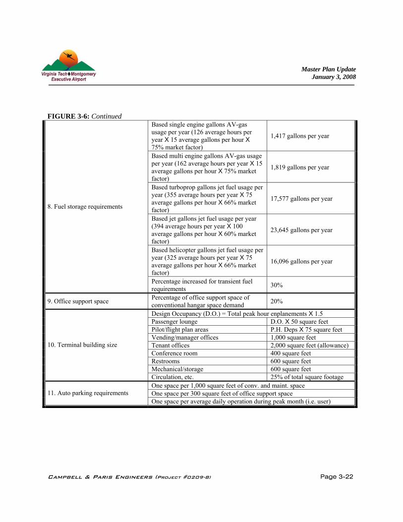
FIGURE 3-6: Continued
Based single engine gallons AV-gas usage per year (126 average hours per year X 15 average gallons per hour X 75% market factor)
1,417 gallons per year
Based multi engine gallons AV-gas usage per year (162 average hours per year X 15 average gallons per hour X 75% market factor)
1,819 gallons per year
Based turboprop gallons jet fuel usage per year (355 average hours per year X 75 average gallons per hour X 66% market factor)
17,577 gallons per year
Based jet gallons jet fuel usage per year (394 average hours per year X 100 average gallons per hour X 60% market factor)
23,645 gallons per year
Based helicopter gallons jet fuel usage per year (325 average hours per year X 75 average gallons per hour X 66% market factor)
16,096 gallons per year
8. Fuel storage requirements
Percentage increased for transient fuel requirements 30%
9. Office support space Percentage of office support space of conventional hangar space demand 20%
Design Occupancy (D.O.) = Total peak hour enplanements X 1.5 Passenger lounge D.O. X 50 square feet Pilot/flight plan areas P.H. Deps X 75 square feet Vending/manager offices 1,000 square feet Tenant offices 2,000 square feet (allowance) Conference room 400 square feet Restrooms 600 square feet Mechanical/storage 600 square feet
10. Terminal building size
Circulation, etc. 25% of total square footage One space per 1,000 square feet of conv. and maint. space One space per 300 square feet of office support space 11. Auto parking requirements One space per average daily operation during peak month (i.e. user)

Master Plan Update January 3, 2008
Campbell & Paris Engineers (Project #0209-8) Page 3-23
3.6 AIRSPACE PROTECTION Protecting the airspace around a public use airport is one of the most important aspects of maintaining an airfield’s safety and utility, as well as protecting the safety of the surrounding community. This responsibility rests with the airport sponsor, but relies heavily on the support and cooperation of the FAA, DOAV and surrounding local municipalities. The goal of protecting an airport's airspace is to prevent "obstructions" from penetrating the defined limits of the protected airspace. If the presence of an obstruction can not be removed or prevented, an evaluation must be done to determine if the potential effects of that obstruction can be mitigated (i.e. marking and lighting or threshold displacement) or if approach minimums/procedures need to be altered. FAA and DOAV grant assurances require the sponsor to do everything that is reasonably within their power to remove and prevent obstructions from occurring. There are two separate, though not unrelated, sets of FAA standards that must be considered when evaluating airspace protection concerns. These are Federal Aviation Regulations (FAR) Part 77 "Objects Affecting Navigable Airspace" and "Terminal Instrument Procedures" (TERPS). Obstructions are defined as any existing or proposed manmade object, object of natural growth or terrain that is at a greater height than any of the "imaginary surfaces" as defined by Part 77 or TERPs. Specified clearance above public roads, railways and waterways is also required to account for any vehicles that traverse the area. Part 77 surfaces must provide at least 17 feet over an interstate highway, 15 feet over other public roads, 10 feet over private roads, and 23 feet over railroads. Imaginary surfaces are three dimensional planes with specific dimensions and slopes that are determined by the type of approaches available to each runway end. The airspace analysis performed for this Master Plan Update focuses on identifying existing and potential obstructions (through vegetation growth) to the existing surfaces (Figures 3-7 & 3-8). The analysis is based on aerial photogrametric mapping obtained in 2003 and imaginary surface elevations provide for ±5 feet of buffer to account for survey accuracy and tree growth. It should be noted that the Airport Authority has an on-going vegetation removal that has removed some of the Part 77 penetrations listed in this analysis. The following is a brief description of the Part 77 and TERPS surfaces that were evaluated for this Master Plan Update. Existing concerns are discussed below. Future concerns will be discussed with the recommended Alternative Layout in Section 4 when a recommended runway layout is provided.

Master Plan Update January 3, 2008
Campbell & Paris Engineers (Project #0209-8) Page 3-24
3. 6.1 Existing Concerns Part 77 Primary Surface – Two penetrations to the primary surface exist. The most noticeable is a
440 foot long line of trees parallel to the runway’s the northeastern end. This line of trees is roughly 240’ off the runway centerline, close to the primary surface boundary. These trees are 30’-40’ tall.
The Second penetration is a 70 foot long area of a group of trees located mid-length down the
runway that is on the northeastern side of the runway approximately 249 feet from the runway centerline. The trees are 30-40’ tall. Although a precision approach is not currently on or planned for the Runway 12 approach, measures should be taken to allow for this option as technology changes that could allow for the implementation of a precision approach. Precision approaches require a 1,000’ primary surface. A 1,000’ Primary Surface would require significant grading to the terrain surrounding the runway. In addition to grading the area to meet standards the primary surface would also need to be free of trees, roads, and structures. See Section 4.1.6 for additional analysis on the creation of a 1,000’ Primary Surface.
Part 77 Approach Surfaces - As described previously, the existing runway is 4,548' long and supports non-precision, instrument approaches to Runway 12 with visibility minimums ≥1 mile and visual approaches to Runway 30. This provides a 34:1 approach slope for Runway 12 and a 20:1 approach slope for Runway 30. As noted on the previous Master Plan, the FAA standard 15' clearance over a public road presents a 5-6 foot penetration for Tech Center Drive. Two obstruction lights are located along Tech Center Drive to indicate a 15 foot obstruction. This situation can be corrected if the runway is expanded or relocated.
As discussed above, a precision approach is not currently on or planned for the Runway 12
approach, however, measures should be taken to protect this option as technology changes. A Precision approach to Runway 12 would provide a 50:1 approach slope.
Part 77 Transitional Surface – Several Vegetative penetrations exist to the Transitional Surface. These include the 5 separate stands northeast of Runway 30 and between 250’ and 700’ off of Runway 30’s centerline. These tree stands penetrate the 7:1 transition surface by 1’ to 35’ in height. In addition, several penetrations exist to the northeast of Runway 12 adjacent to the Huckleberry Trail. South of Runway 30 across Ramble Road is three stands of Trees that penetrate up to 17’ of the transitional surface.

Master Plan Update January 3, 2008
Campbell & Paris Engineers (Project #0209-8) Page 3-25
Finally, 12’ of the old Group Hangar is a 6’ penetration of the Transitional Surface.
Part 77 Horizontal Surface – The Horizontal Surface begins at an elevation of 2282msl and is penetrated by terrain features such as High Knob, the Ridge that the Blacksburg Municipal Golf Course is located on, and Price’s Mountain.
Part 77 Conical Surface - The Conical Surface is penetrated by portions of Price’s Mountain as
well.
FIGURE 3-7: Existing Part 77 Penetrations, Runway 12
Master Plan Update January 3, 2008
Campbell & Paris Engineers (Project #0209-8) Page 3-26
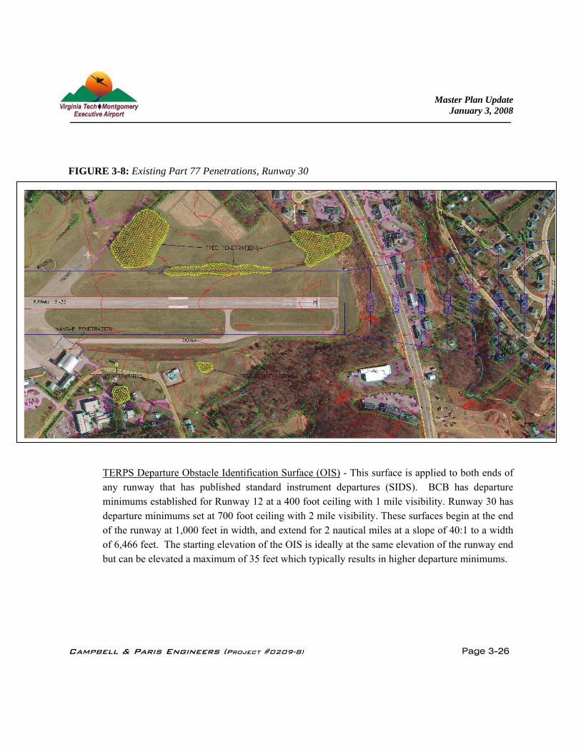
FIGURE 3-8: Existing Part 77 Penetrations, Runway 30 TERPS Departure Obstacle Identification Surface (OIS) - This surface is applied to both ends of
any runway that has published standard instrument departures (SIDS). BCB has departure minimums established for Runway 12 at a 400 foot ceiling with 1 mile visibility. Runway 30 has departure minimums set at 700 foot ceiling with 2 mile visibility. These surfaces begin at the end of the runway at 1,000 feet in width, and extend for 2 nautical miles at a slope of 40:1 to a width of 6,466 feet. The starting elevation of the OIS is ideally at the same elevation of the runway end but can be elevated a maximum of 35 feet which typically results in higher departure minimums.

Master Plan Update January 3, 2008
Campbell & Paris Engineers (Project #0209-8) Page 3-27
3.6.2 Local Zoning Ordinances Both the Town of Blacksburg and Montgomery County have established an Airport Safety Zone Ordinance. Their function is to protect the airspace and communities surrounding the Virginia Tech-Montgomery Executive Airport and is consistent with the requirements of the FAA grant assurances for sponsors receiving Airport Improvement Program Funds. The Ordinance identifies Approach Zones and Safety Zones surrounding the airport, which are based on prescribed FAA Part 77 surfaces. The Ordinance also describes the use limitations within these zones and the enforcement mechanisms. In addition to the local site plan review process, development on or near airports must also be reviewed by the FAA, where applicable, in accordance with the 7460 Form process; “Notice of Proposed Construction or Alteration”. The limits of this notification area generally extend 20,000 feet from the nearest point of any runway (longer than 3200 feet). Additionally any proposed structure in excess of 200' above ground level must also follow the Federal 7460 process. It should also be noted that land use zoning around the airport generally includes:
1. Airport property and South to Route 460 Bypass is zoned RD, Research & Development. 2. To the North is University and Residential 3. To the West is University and Agriculture. 4. To the East is Commercial
The Airport Authority should coordinate with the surrounding jurisdictions to reduce the density of residential zoning located within its eastern approaches or recommend zoning (such as agricultural, office, commercial, or industrial) that is more compatible with an airport approach. When possible the Airport Authority should also seek to have placed in the deeds of residential property near the airport a notice to the property owner that they live near an airport and may be impacted by some noise.
Master Plan Update January 3, 2008
Campbell & Paris Engineers (Project #0209-8) Page 3-28
3.7 LAND AND EASEMENT ACQUISITION In order for the Airport Authority to implement the recommended facility improvements in an efficient and effective manner, and continue to protect the surrounding airspace, additional property interests will be needed. This can be achieved through a combination of fee-simple land and easement acquisition of several adjacent parcels. These acquisitions will provide the needed ground area for the future runway extensions as well as protection of the airport’s existing and future RPZ’s. For planning purposes, recommended acquisitions are based on the full ownership of the RPZ to Runway 12/30.