Embed Size (px)
Citation preview
Special
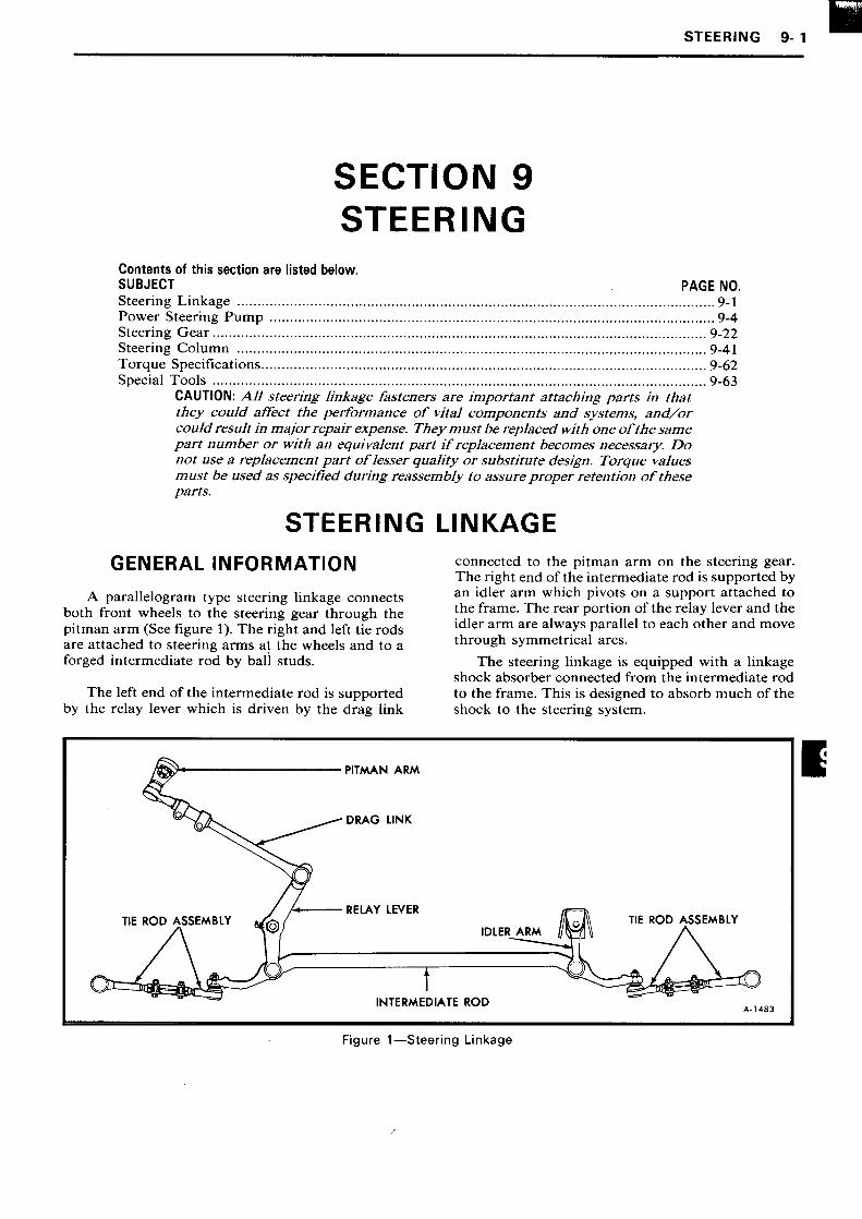
A parallelogram type steering linkage connectsboth front wheels to the steering gear through thepitman arm (See figure 1) . The right and left tie rodsare attached to steering arms at the wheels and to aforged intermediate rod by ball studs.
The left end of the intermediate rod is supportedby the relay lever which is driven by the drag link
SECTION 9STEERING
Contents of this section are listed below.SUBJECT
PAGE NO.Steering Linkage . . . . . . . . . . . . . . . . . . . . . . . . . . . . . . . . . . . . . . . . . . . . . . . . . . . . . . . . . . . . . . . . . . . . . . . . . . . . . . . . . . . . . . . . . . . . . . . . . . . . . . . . . . . . . . . . . . . . ..9-1Power Steering Pump . . . . . . . . . . . . . . . . . . . . . . . . . . . . . . . . . . . . . . . . . . . . . . . . . . . . . . . . . . . . . . . . . . . . . . . . . . . . . . . . . . . . . . . . . . . . . . . . . . . . . . . . . . . . ..9-4Steering Gear . . . . . . . . . . . . . . . . . . . . . . . . . . . . . . . . . . . . . . . . . . . . . . . . . . . . . . . . . . . . . . . . . . . . . . . . . . . . . . . . . . . . . . . . . . . . . . . . . . . . . . . . . . . . . . . . . . . . . . . . . . 9-22Steering Column .. . . . . . . . . . . . . . . . . . . . . . . . . . . . . . . . . . . . . . . . . . . . . . . . . . . . . . . . . . . . . . . . . . . . . . . . . . . . . . . . . . . . . . . . . . . . . . . . . . . . . . . . . . . . . . . . . . . 9-41Torque Specifications . . . . . . . . . . . . . . . . . . . . . . . . . . . . . . . . . . . . . . . . . . . . . . . . . . . . . . . . . . . . . . . . . . . . . . . . . . . . . . . . . . . . . . . . . . . . . . . . . . . . . . . . . . . . . . 9-62
Tools . . . . . . . . . . . . . . . . . . . . . . . . . . . . . . . . . . . . . . . . . . . . . . . . . . . . . . . . . . . . . . . . . . . . . . . . . . . . . . . . . . . . . . . . . . . . . . . . . . . . . . . . . . . . . . . . . . . . . . . . . . 9-63CAUTION : All steering linkage fasteners are important attaching parts in thatthey could affect the performance of vital components and systems and/orcould resultin majorrepairexpense. Theymust be replaced with oneofthe samepart number or with an equivalent part ifreplacement becomes necessary. Donot use a replacement part oflesser quality or substitute design . Torque valuesmust be used as specified during reassembly to assure proper retention oftheseparts.
STEERING LINKAGEGENERAL INFORMATION
Figure 1-Steering Linkage
STEERING
9- 1
connected to the pitman arm on the steering gear.The right end of the intermediate rod is supported byan idler arm which pivots on a support attached tothe frame. The rear portion of the relay lever and theidler arm are always parallel to each other and movethrough symmetrical arcs .
The steering linkage is equipped with a linkageshock absorber connected from the intermediate rodto the frame. This is designed to absorb much of theshock to the steering system .
9- 2
STEERING
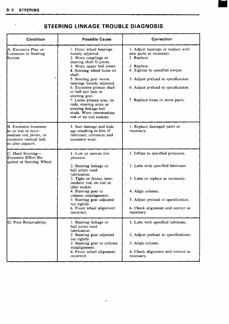
STEERING LINKAGE TROUBLE DIAGNOSIS
Condition
A. Excessive Play orLooseness in SteeringSystem
Possible Cause
1 . Front wheel bearingsloosely adjusted .2. Worn couplings orsteering shaft U-joints.3. Worn upper ball joints .4. Steering wheel loose onshaft.5. Steering gear wormbearings loosely adjusted .6. Excessive pitman shaftto ball nut lash insteering gear .7. Loose pitman arm, tierods, steering arms orsteering linkage ballstuds. Worn intermediaterod or tie rod sockets.
Correction
1 . Adjust bearings or replace withnew parts as necessary.2. Replace.
3. Replace.4 . Tighten to specified torque .
5 . Adjust preload to specification .
6. Adjust preload to specification .
7 . Replace loose or worn parts.
B. Excessive loosenessin tie rod or inter-mediate rod pivots, orexcessive vertical lashin idler support.
1 . Seal damage and leak-age resulting in loss oflubricant, corrosion andexcessive wear .
1 . Replace damaged parts asnecessary.
C. Hard Steering-Excessive Effort Re-quired at Steering Wheel .
D. Poor Returnability.
1 . Low or uneven tirepressure .
2. Steering linkage orball joints needlubrication.3 . Tight or frozen inter-mediate rod, tie rod oridler socket .4. Steering gear tocolumn misalignment .5 . Steering gear adjustedtoo tightly.6. Front wheel alignmentincorrect.
1 . Steering linkage orball joints needlubrication .2. Steering gear adjustedtoo tightly.3 . Steering gear to columnmisalignment.4. Front wheel alignmentincorrect.
1 . Inflate to specified pressures.
2. Lube with specified lubricant.
3. Lube or replace as necessary.
4. Align column .
5. Adjust preload to specification .
6. Check alignment and correct asnecessary.
1 . Lube with specified lubricant.
2. Adjust preload to specifications .
3. Align column.
4. Check alignment and correct asnecessary.
IMPORTANT: Lubricate the steering linkagesockets whenever servicing the linkage.
The vehicle employs two three-piece tie rods con-necting left and right steering arms (See figure 1) .The tie rod assembly consists of a tube and twosocket end assemblies . The socket end assemblies arethreaded into the tube and locked in place withclamps . Right and left hand threads are provided tofacilitate toe-in adjustment.
The tie rod ends require no attention in serviceother than periodic lubrication and inspection to seethat the ball studs are tight. Socket ends should bereplaced when excessive up and down motion or anylost motion or end play at ball end of studs exists .
REMOVAL (FIGURE 1)1 . Raise vehicle.
STEERING LINKAGE COMPONENT REPLACEMENT
TIE RODS
2. Remove front wheels .
3. Remove cotter pin from ball studs and removecastellated nuts .
4. Disconnect tie rod from steering arm by usingTool J-24319 or similar puller .
5 . Remove inner ball stud from intermediate rodusing procedure described in Step 3 and 4.
6. To remove tie rod ends from the adjuster tube,loosen clamp bolts and unscrew end assemblies .
INSTALLATION1 . If the tie rod ends were removed, lubricate the
threads with chassis lube . Thread both ends of therod an equal distance into the adjuster tube .
2. Make sure that threads on ball studs and in ballstud nuts are perfectly clean and smooth . The ballstud must have no nicks on the taper.
NOTE : If threads are not clean and smooth, ballstuds may turn in tie rod ends when attemptingto tighten nut.
3. Install ball studs in steering arms and inter-mediate rod.
4. Install ball stud nuts and torque . See specifica-tions for torque value and procedure.
STEERING
9- 3
5. Lubricate linkage sockets.
6. Lower vehicle.
7. Adjust toe-in (See section 3A of this manual).
DRAG LINK (FIGURE 1)
The procedures for the removal and installationof the drag link are the same as those given for thetie rods, earlier in this section. If the drag link wasdisassembled or a new unit is installed the adjust-ment on the drag link should coincide with the steer-ing wheel at the center of its' travel and the wheelspointing straight ahead.
NOTE: Later production vehicles are equippedwith a non-adjustable drag link .
RELAY LEVER (FIGURE 1)REMOVAL
1 . Place vehicle on hoist.
2. Remove cotter pins and castellated nuts fromboth ends of the relay lever.
3 . Disconnect drag link from relay lever by usingTool J-24319 or similar puller .
4. Disconnect intermediate rod from relay leverusing puller as in step 3 .
5 . Remove bolt securing relay lever to frame.
INSTALLATION1 . Secure relay lever to frame with bolt and
torque bolt to 250 to 300 foot-pounds.
2. Connect relay lever ball stud to intermediaterod.
3 . Install drag link ball stud to relay lever.
4. Install ball stud nuts, making sure threads areclean, and torque the intermediate rod, and the draglink stud nuts .
5 . Lubricate all steering linkage sockets.
6. Lower vehicle.
9- 4
STEERING
IDLER ARM
REMOVAL (FIGURE 1)1 . Raise vehicle.
2. Remove cotter pin and castellated nut fromidler arm ball stud at intermediate rod.
3 . Disconnect idler arm from intermediate rodusing Tool J-24319 or similar puller .
4. Remove bolt and nut securing idler arm toframe.
INSTALLATION1 . Secure idler arm to frame using bolt and lock
nut. Torque nut to 85 to 110 foot pounds .
2 . Connect idler arm ball stud to intermediaterod. Install ball stud nut making sure threads areclean, and torque. See specifications for torque valueand procedures .
3. Lubricate all steering linkage sockets as de-scribed in SECTION 0 of this manual .
4. Lower vehicle.
POWER STEERING PUMP
Figure 2-Power Steering Pump (Exploded)
GENERAL INFORMATION
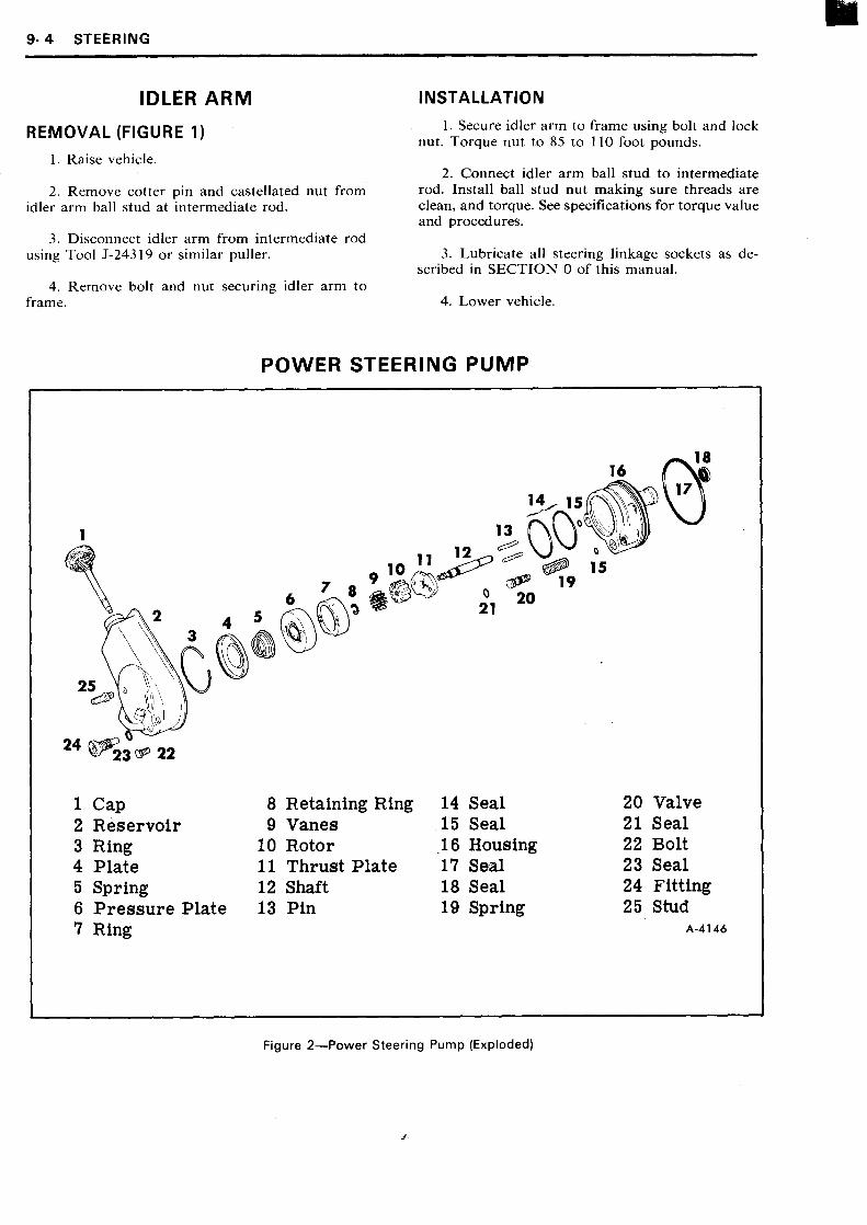
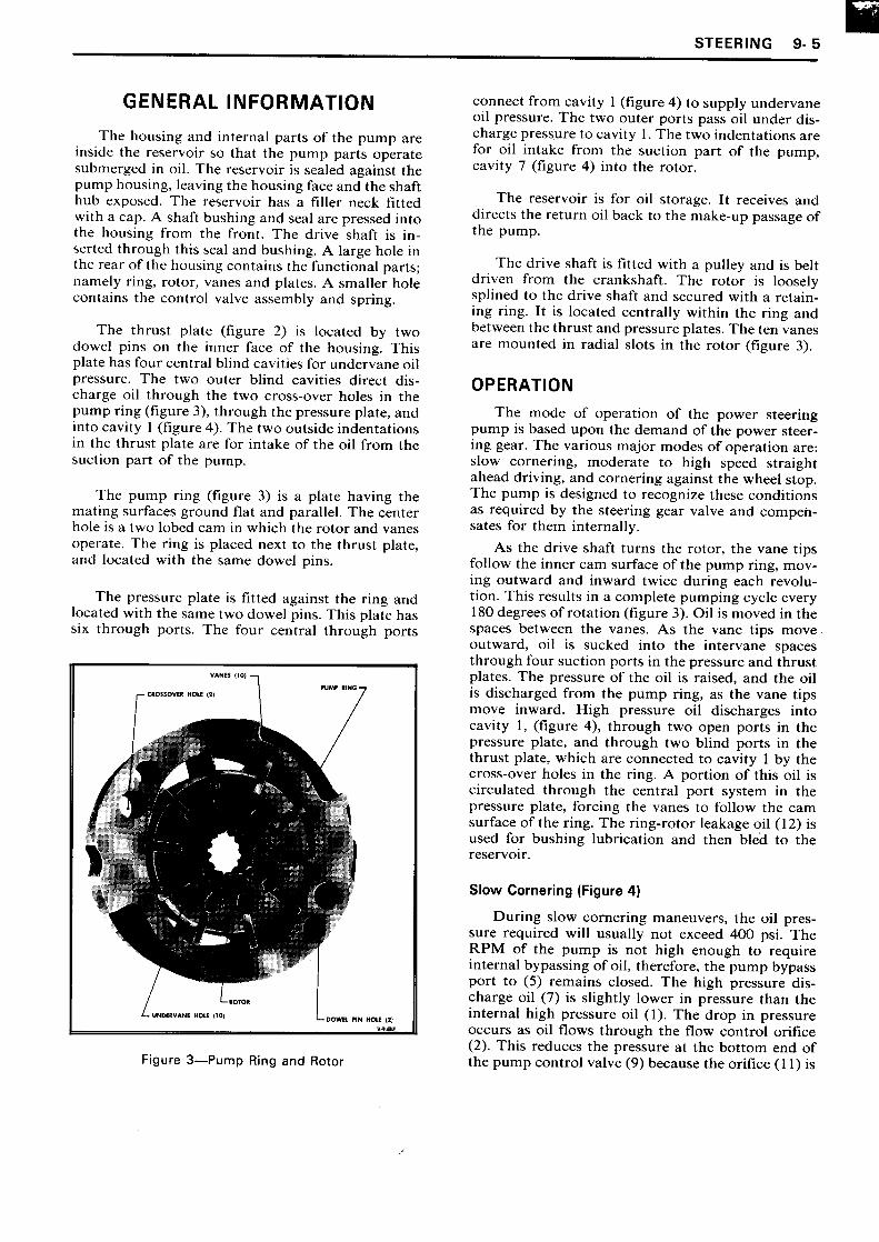
The housing and internal parts of the pump areinside the reservoir so that the pump parts operatesubmerged in oil. The reservoir is sealed against thepump housing, leaving the housing face and the shafthub exposed. The reservoir has a filler neck fittedwith a cap. A shaft bushing and seal are pressed intothe housing from the front . The drive shaft is in-serted through this seal and bushing. A large hole inthe rear of the housing contains the functional parts;namely ring, rotor, vanes and plates . A smaller holecontains the control valve assembly and spring.
The thrust plate (figure 2) is located by twodowel pins on the inner face of the housing. Thisplate has four central blind cavities for undervane oilpressure. The two outer blind cavities direct dis-charge oil through the two cross-over holes in thepump ring (figure 3), through the pressure plate, andinto cavity 1 (figure 4) . The two outside indentationsin the thrust plate are for intake of the oil from thesuction part of the pump.
The pump ring (figure 3) is a plate having themating surfaces ground flat and parallel . The centerhole is a two lobed cam in which the rotor and vanesoperate. The ring is placed next to the thrust plate,and located with the same dowel pins .
The pressure plate is fitted against the ring andlocated with the same two dowel pins . This plate hassix through ports. The four central through ports
Figure 3-Pump Ring and Rotor
OPERATION
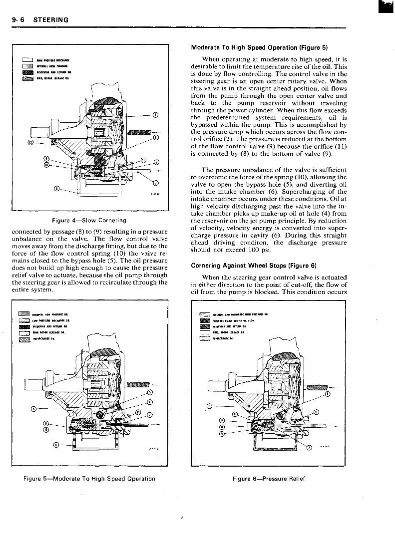
Slow Cornering (Figure 4)
STEERING
9- 5
connect from cavity 1 (figure 4) to supply undervaneoil pressure . The two outer ports pass oil under dis-charge pressure to cavity 1 . The two indentations arefor oil intake from the suction part of the pump,cavity 7 (figure 4) into the rotor.
The reservoir is for oil storage. It receives anddirects the return oil back to the make-up passage ofthe pump.
The drive shaft is fitted with a pulley and is beltdriven from the crankshaft . The rotor is looselysplined to the drive shaft and secured with a retaining ring . It is located centrally within the ring andbetween the thrust and pressure plates . The ten vanesare mounted in radial slots in the rotor (figure 3) .
The mode of operation of the power steeringpump is based upon the demand of the power steer-ing gear . The various major modes of operation are:slow cornering, moderate to high speed straightahead driving, and cornering against the wheel stop .The pump is designed to recognize these conditionsas required by the steering gear valve and compen-sates for them internally .
As the drive shaft turns the rotor, the vane tipsfollow the inner cam surface of the pump ring, mov-ing outward and inward twice during each revolution . This results in a complete pumping cycle every180 degrees of rotation (figure 3) . Oil is moved in thespaces between the vanes. As the vane tips moveoutward, oil is sucked into the intervane spacesthrough four suction ports in the pressure and thrustplates . The pressure of the oil is raised, and the oilis discharged from the pump ring, as the vane tipsmove inward . High pressure oil discharges intocavity 1, (figure 4), through two open ports in thepressure plate, and through two blind ports in thethrust plate, which are connected to cavity 1 by thecross-over holes in the ring . A portion of this oil iscirculated through the central port system in thepressure plate, forcing the vanes to follow the camsurface of the ring . The ring-rotor leakage oil (12) isused for bushing lubrication and then bled to thereservoir.
During slow cornering maneuvers, the oil pres-sure required will usually not exceed 400 psi. TheRPM of the pump is not high enough to requireinternal bypassing of oil, therefore, the pump bypassport to (5) remains closed . The high pressure dis-charge oil (7) is slightly lower in pressure than theinternal high pressure oil (1). The drop in pressureoccurs as oil flows through the flow control orifice(2). This reduces the pressure at the bottom end ofthe pump control valve (9) because the orifice (11) is
9- 6
STEERING
Figure 4-Slow Cornering
connected by passage (8) to (9) resulting in a pressureunbalance on the valve. The flow control valvemoves away from the discharge fitting, but due to theforce of the flow control spring (10) the valve re-mains closed to the bypass hole (5). The oil pressuredoes not build up high enough to cause the pressurerelief valve to actuate, because the oil pump throughthe steering gear is allowed to recirculate through theentire system .
Figure 5-Moderate To High Speed Operation
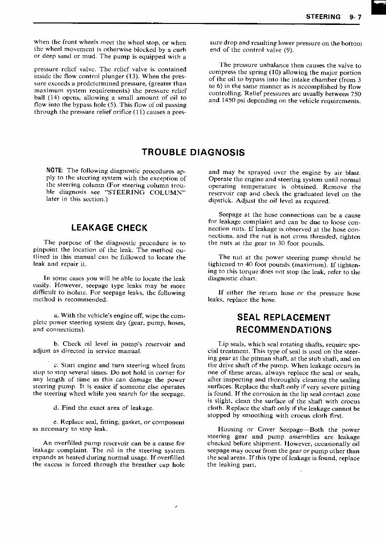
Moderate To High Speed Operation (Figure 5)
When operating at moderate to high speed, it isdesirable to limit the temperature rise of the oil . Thisis done by flow controlling. The control valve in thesteering gear is an open center rotary valve. Whenthis valve is in the straight ahead position, oil flowsfrom the pump through the open center valve andback to the pump reservoir without travelingthrough the power cylinder . When this flow exceedsthe predetermined system requirements, oil isbypassed within the pump . This is accomplished bythe pressure drop which occurs across the flow con-trol orifice (2). The pressure is reduced at the bottomof the flow control valve (9) because the orifice (11)is connected by (8) to the bottom of valve (9).
The pressure unbalance of the valve is sufficientto overcome the force of the spring (10), allowing thevalve to open the bypass hole (5), and diverting oilinto the intake chamber (6). Supercharging of theintake chamber occurs under these conditions . Oil athigh velocity discharging past the valve into the in-take chamber picks up make-up oil at hole (4) fromthe reservoir on the jet pump principle. By reductionof velocity, velocity energy is converted into super-charge pressure in cavity (6). During this straightahead driving conditon, the discharge pressureshould not exceed 100 psi.
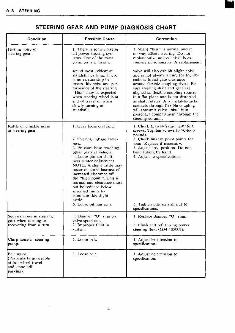
Cornering Against Wheel Stops (Figure 6)
When the steering gear control valve is actuatedin either direction to the point of cut-off, the flow ofoil from the pump is blocked. This condition occurs
Figure 6-Pressure Relief
when the front wheels meet the wheel stop, or whenthe wheel movement is otherwise blocked by a curbor deep sand or mud. The pump is equipped with a
pressure relief valve. The relief valve is containedinside the flow control plunger (13) . When the pres-sure exceeds a predetermined pressure, (greater thanmaximum system requirements) the pressure reliefball (14) opens, allowing a small amount of oil toflow into the bypass hole (5). This flow of oil passingthrough the pressure relief orifice (11) causes a pres-
NOTE : The following diagnostic procedures ap-ply to the steering system with the exception ofthe steering column (For steering column trou-ble diagnosis see "STEERING COLUMN"later in this section.)
LEAKAGE CHECK
The purpose of the diagnostic procedure is topinpoint the location of the leak . The method ou-tlined in this manual can be followed to locate theleak and repair it .
In some cases you will be able to locate the leakeasily . However, seepage type leaks may be moredifficult to isolate. For seepage leaks, the followingmethod is recommended.
a. With the vehicle's engine off, wipe the com-plete power steering system dry (gear, pump, hoses,and connections) .
b. Check oil level in pump's reservoir andadjust as directed in service manual .
c. Start engine and turn steering wheel fromstop to stop several times. Do not hold in corner forany length of time as this can damage the powersteering pump . It is easier if someone else operatesthe steering wheel while you search for the seepage.
d. Find the exact area of leakage.
e. Replace seal, fitting, gasket, or componentas necessary to stop leak .
An overfilled pump reservoir can be a cause forleakage complaint. The oil in the steering systemexpands as heated during normal usage. If overfilledthe excess is forced through the breather cap hole
TROUBLE DIAGNOSIS
STEERING
9- 7
sure drop and resulting lower pressure on the bottomend of the control valve (9).
The pressure unbalance then causes the valve tocompress the spring (10) allowing the major portionof the oil to bypass into the intake chamber (from 3to 6) in the same manner as is accomplished by flowcontrolling . Relief pressures are usually between 750and 1450 psi depending on the vehicle requirements .
and may be sprayed over the engine by air blast.Operate the engine and steering system until normaloperating temperature is obtained. Remove thereservoir cap and check the graduated level on thedipstick . Adjust the oil level as required .
Seepage at the hose connections can be a causefor leakage complaint and can be due to loose con-nection nuts . If leakage is observed at the hose connections, and the nut is not cross threaded, tightenthe nuts at the gear to 30 foot pounds .
The nut at the power steering pump should betightened to 40 foot pounds (maximum). If tighten-ing to this torque does not stop the leak, refer to thediagnostic chart.
If either the return hose or the pressure hoseleaks, replace the hose .
SEAL REPLACEMENTRECOMMENDATIONS
Lip seals, which seal rotating shafts, require spe-cial treatment. This type of seal is used on the steer-ing gear at the pitman shaft, at the stub shaft, and onthe drive shaft of the pump. When leakage occurs inone of these areas, always replace the seal or seals,after inspecting and thoroughly cleaning the sealingsurfaces . Replace the shaft only if very severe pittingis found. If the corrosion in the lip seal contact zoneis slight, clean the surface of the shaft with crocuscloth. Replace the shaft only if the leakage cannot bestopped by smoothing with crocus cloth first .
Housing or Cover Seepage-Both the powersteering gear and pump assemblies are leakagechecked before shipment . However, occasionally oilseepage may occur from the gear or pump other thanthe seal areas. If this type of leakage is found, replacethe leaking part.
9- 8
STEERING
STEERING GEAR AND PUMP DIAGNOSIS CHART
Condition Possible Cause Correction
Hissing noise in 1 . There is some noise in 1 . Slight "hiss" is normal and insteering gear . all power steering sys- no way affects steering . Do not
tems . One of the most replace valve unless "hiss" is ex-common is a hissing tremely objectionable. A replacement
sound most evident at valve will also exhibit slight noisestandstill parking. There and is not always a cure for the ob-is no relationship be- jection. Investigate clearancetween this noise and per- around flexible coupling rivets . Beformance of the steering . sure steering shaft and gear are"Hiss" may be expected aligned so flexible coupling rotateswhen steering wheel is at in a flat plane and is not distortedend of travel or when as shaft rotates. Any metal-to-metalslowly turning at contacts through flexible couplingstandstill . will transmit valve "hiss" into
passenger compartment through thesteering column .
Rattle or chuckle noise 1 . Gear loose on frame. 1 . Check gear-to-frame mountingin steering gear . screws . Tighten screws to 70-foot-
pounds .2. Steering linkage loose- 2. Check linkage pivot points forness . wear . Replace if necessary.3. Pressure hose touching 3 . Adjust hose position . Do notother parts of vehicle. bend tubing by hand .4. Loose pitman shaft 4. Adjust to specifications .over center adjustmentNOTE: A slight rattle mayoccur on turns because ofincreased clearance offthe "high point." . This isnormal and clearance mustnot be reduced belowspecified limits toeliminate this slightrattle .5 . Loose pitman arm. 5. Tighten pitman arm nut to
specifications .
Squawk noise in steering 1 . Damper "O" ring on 1 . Replace damper "O" ring .gear when turning or valve spool cut.recovering from a turn . 2 . Improper fluid in 2. Flush and refill using power
system . steering fluid (GM 105007).
Chirp noise in steering 1 . Loose belt . 1 . Adjust belt tension topump . specification .
Belt squeal 1. Loose belt . 1 . Adjust belt tension to(Particularly noticeable specification .at full wheel traveland stand stillparking) .
STEERING
9- 9
STEERING GEAR AND PUMP DIAGNOSIS CHART (Cont'd.)
Condition Possible Cause Correction
Growl noise in steering 1 . Excessive back pressure I . Locate restriction and correct.,pump. in hoses or steering gear Replace part if necessary.caused by restriction .
Growl noise in steering 1 . Scored pressure plates, 1 . Replace parts and flush system.pump. (Particularly thrust plate or rotor.noticeable at standstill parking) .
2 . Extreme wear of cam 2. Replace parts.ring .
Groan noise in steering 1 . Low oil level. 1 . Fill reservoir to proper level.pump .
2. Air in the oil. Poor 2 . Tighten connector to specifiedpressure hose connection . torque . Bleed system by operating
steering from right to left-fullturn .
Rattle or knock noise 1 . Loose pump pulley nut. 1 . Tighten nut to specified torque .in steering pump.
Rattle noise in steering 1 . Vanes not installed 1 . Install properly .pump. properly .
2 . Vanes sticking in rotor 2 . Free up by removing burrs,slots. varnish or dirt .
Swish noise in steering 1 . Defective flow control 1. Replace part.pump. valve.
Whine noise in steering 1 . Pump shaft bearing 1 . Replace housing and shaft . Flushpump . scored . system .
Poor return of steering 1 . Lack of lubrication in 1 . Lube linkage and ball joints .wheel to center . linkage and ball joints .
2 . Lower coupling flange 2. Loosen pinch bolt and assemblerubbing against steering properly .gear adjuster plug .3. Steering gear to column 3 . Align steering column .
_ misalignment .4. Tires not properly 4. Inflate to specified pressure .inflated .5. Improper front wheel 5. Check and adjust as necessary.alignment. With front wheels still on alignment
pads of front end machine, discon-nect pitman arm of linkage frompitman shaft of gear . Turn frontwheels by hand . If wheels will notturn or are difficult to turn,determine if linkage or balljoints are binding.
9- 1 0
STEERING
STEERING GEAR AND PUMP DIAGNOSIS CHART (Cont'd .)
Condition Possible Cause Correction
6 . Steering linkage 6. Replace pivots .binding.7 . Ball joints binding. 7. Replace ball joints .(Turn steering wheel andlisten for internalrubbing in column-checkcauses listed and correctas directed).8 . Steering wheel rubbing 8. Adjust steering jacket .against directionalsignal housing.9 . Tight or frozen 9. Replace bearings.steering shaft bearings .10 . Rubber spacer binding. 10 . Make certain spacer is properly
seated . Lubricate inside diameterwith silicone .
11 . Sticky or plugged 11 . Remove and clean or replacevalve spool. valve.12 . Steering gear adjust- 12 . Check adjustment with gear outments over specifications . of vehicle. Adjust as required .
Vehicle wanders. 1 . Front end mis- 1 . Adjust to specifications .(Keep in mind road con- aligned.dition and wind . Testvehicle on flat road go-ing in both directions) .
2 . Unbalanced steering 2. Replace valve.gear valve.NOTE: If this is cause,steering effort will be
- very light in direction oflead and heavy in op-posite direction .
Momentary increase in 1 . Low oil level in pump . 1 . Add power steering fluid aseffort when turning required .wheel fast to right orleft .
2 . Pump belt slipping . 2. Tighten or replace belt .- 3 . High internal leakage. 3. Check pump pressure . (See pump
pressure test).
STEERING
9- 1 1
STEERING GEAR AND PUMP DIAGNOSIS CHART (Cont'd.)
Condition Possible Cause Correction
Steering wheel surges or 1 . Low oil level. 1. Fill as required .jerks when turning withengine running espe-cially during parking.
2 . Loose pump belt . 2. Adjust tension to specification .
3. Steering linkage hit- 3 . Correct clearance.ting engine oil pan atfull turn .4. Insufficient pump 4. Check pump pressure . (See pumppressure . pressure test).
Replace relief valve if defective.5. Sticky flow control 5 . Inspect for varnish or damage,valve. replace if necessry .
Excessive wheel kick- 1 . Air in system . 1 . Add oil to pump reservoir andback or loose steering . bleed by operating steering .
Check hose connectors for propertorque and adjust as required .
2. Steering gear loose on 2. Tighten attaching screws toframe. specified torque .3 . Steering gear flexible 3. Tighten flange pinch bolts tocoupling loose on shaft 30 foot-pounds, if serrations areor rubber disc mounting not damaged. Tighten upper flangescrews loose. to coupling nuts to specified
torque .4. Steering linkage joints 4. Replace loose pivots .worn enough to be loose.5 . Worn poppet valve 5. Replace poppet valve.(Gear) .6. Loose thrust bearing 6. Adjust to specification withpreload adjustment . gear out of vehicle.(Gear) .7. Excessive "over-center" 7. Adjust to specification withlash . gear out of vehicle.
Hard steering or lack 1 . Loose pump belt . 1 . Adjust belt tension toof assist. specification .
2. Low oil level in res- 2. Fill to proper level. If exces-ervoir . sively low, check all lines and
joints for evidence of externalleakage. Tighten loose connectorsto 30-ft-lbs.
NOTE: Low oil level willalso result in excessivepump noise.3 . Steering gear to column 3. Align steering column .misalignment.4. Lower coupling flange 4. Loosen pinch bolt and assemblerubbing against steer- properly .ing gear adjuster plug .
9- 12
STEERING
STEERING GEAR AND PUMP DIAGNOSIS CHART (Cont'd .)
POWER STEERING SYSTEM TEST PROCEDURE
1 . Disconnect pressure hose at union of pump, usea small container to catch any fluid which mightleak .2 . Connect a spare pressure hose to pump union.3 . Using pressure gage J 5176-1, adapter fittingJ 22326, connect gage to both hoses.4. Open hand valve on gage .5 . Start engine, allow system to reach operatingtemperatures and check fluid level adding any fluidif required . When engine is at normal operatingtemperature, the initial pressure read on the gage(valve open) should be in the 80-125 psi range.Should this pressure be in excess of 200 psi-checkthe hoses for restrictions and the poppet valvefor proper assembly .6. Close gate valve fully 3 times. Record thehighest pressures attained each time . (Note: do notleave valve fully closed for more than 5 secondsas the pump could be damaged internally) .
(a) If the pressures recorded are within1250-1350 psi and the range of readings are within50 psi, the pump is functioning within specs.
(b) If the pressures recorded are high, but donot repeat within 50 psi, the flow controllingvalve is sticking . Remove the valve, clean it andremove any burrs using crocus cloth or fine hone .If the system contains some dirt, flush it . If itis exceptionally dirty, both the pump and the gearmust be completely disassembled, cleaned andreassembled before further usage.
(c) If the pressures recorded are constant, butmore than 100 psi, below the low listed spec .,replace the flow control valve and recheck. If thepressures are still low, replace the rotatinggroup.
s
Condition Possible Cause Correction
5. Tires not properly in- 5 . Inflate to recommended pressure .flated .
NOTE: If checks 1 through Further possible causes In order to diagnose conditions5 do not reveal cause could be : such as listed in 6, 7, 8, 9 aof hard steering, follow test of the entire power steeringthe procedure below to system is required .determine fault.
6. Sticky flow controlvalve.7. Insufficient pumppressure output .8. Excessive internalpump leakage.9. Excessive internal gearleakage.
STEERING
9- 13
STEERING GEAR AND PUMP DIAGNOSIS CHART (Cont'd .)
7 . If the pump checks to specs., leave the valveopen and turn (or have turned) the steering wheelinto both corners. Record the highest pressuresand compare with the maximum pump pressure re-corded . If this pressure cannot be built in either(or one) side of the gear, the gear is leakinginternally and must be disassembled and repaired .8. Shut off engine, remove testing gage, sparehose, reconnect pressure hose, check fluid levelor make needed repairs.
Alternate Power Steering System Test Procedure
NOTE : If power steering analyzer J-25325 isavailable, use it and the following procedure todetermine fault.
1. Connect Analyzer J-25323 into steering system .Remove pressure fitting from gear and connect intofemale analyzer adapter. Thread male adapter ofanalyzer into gear . Connect analyzer to adapters .Tighten both connections to 40 ft . lbs. Add powersteering fluid to pump if required .2. Start engine . Set engine idle to specification .Run engine for approximately five minutes . Checkpower steering fluid level and add if required .3. Record flow and pressure at idle with gatevalve fully open . If flow is below 2gpm, the pumpappears to be in need of repair, but continuediagnosis. If pressure is above 200 psi checkhoses for restrictions and check steering gearfor poppet valve functions.4. Partially close gate valve to build 700 psi.Observe and record flow . If flow drops more than1 gpm, disassemble pump and replace ring, rotor,and vanes. If pressure or thrust plates arecracked or worn, replace.5. Completely close and partially open gate valvethree times (do not allow valve to remain closedmore than 5 seconds. If pressures recorded are100 psi lower than 1250-1350 psi specifications,replace flow control valve in pump . If pressuresrecorded vary more than 50 psi, the flow controlvalve should be removed and cleaned. Also checkcontrol valve bore for dirt, chips, etc. Clean asrequired . If system fluid appears contaminated,both the gear and the pump must be completelydisassembled and cleaned.6. Increase engine speed from idle to approxi-mately 1500 rpm. If the flow varys more than 1gpm, the flow control valve should be removed andcleaned as in step 5 above.
9- 1 4
STEERING
STEERING GEAR AND PUMP DIAGNOSIS CHART (Cont'd .)
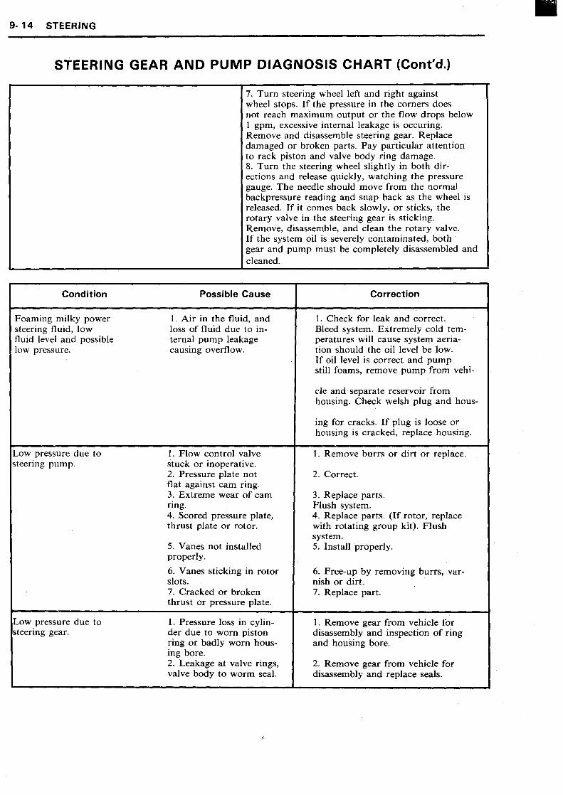
7. Turn steering wheel left and right againstwheel stops. If the pressure in the corners doesnot reach maximum output or the flow drops below1 gpm, excessive internal leakage is occuring .Remove and disassemble steering gear. Replacedamaged or broken parts. Pay particular attentionto rack piston and valve body ring damage .8. Turn the steering wheel slightly in both dir-ections and release quickly, watching the pressuregauge. The needle should move from the normalbackpressure reading and snap back as the wheel isreleased . If it comes back slowly, or sticks, therotary valve in the steering gear is sticking .Remove, disassemble, and clean the rotary valve.If the system oil is severely contaminated, bothgear and pump must be completely disassembled andcleaned.
Condition Possible Cause Correction
Foaming milky power 1 . Air in the fluid, and 1 . Check for leak and correct.steering fluid, low loss of fluid due to in- Bleed system . Extremely cold tem-fluid level and possible ternal pump leakage peratures will cause system aeria-low pressure. causing overflow . tion should the oil level be low .
If oil level is correct and pumpstill foams, remove pump from vehi-
cle and separate reservoir fromhousing. Check welsh plug and hous-
ing for cracks . If plug is loose orhousing is cracked, replace housing.
Low pressure due to 1 . Flow control valve 1 . Remove burrs or dirt or replace .steering pump. stuck or inoperative.
2. Pressure plate not 2. Correct.flat against cam ring .3. Extreme wear of cam 3 . Replace parts .ring . Flush system .4. Scored pressure plate, 4. Replace parts. (If rotor, replacethrust plate or rotor. with rotating group kit) . Flush
system.5. Vanes not installed 5 . Install properly .properly .
6. Vanes sticking in rotor 6. Free-up by removing burrs, var-slots . nish or dirt .7. Cracked or broken 7. Replace part .thrust or pressure plate.
Low pressure due to 1 . Pressure loss in cylin- 1 . Remove gear from vehicle forsteering gear . der due to worn piston disassembly and inspection of ring
ring or badly worn hous- and housing bore,ing bore .2. Leakage at valve rings, 2. Remove gear from vehicle forvalve body to worm seal . disassembly and replace seals.
25-30 FT. LBS.
ENGINE
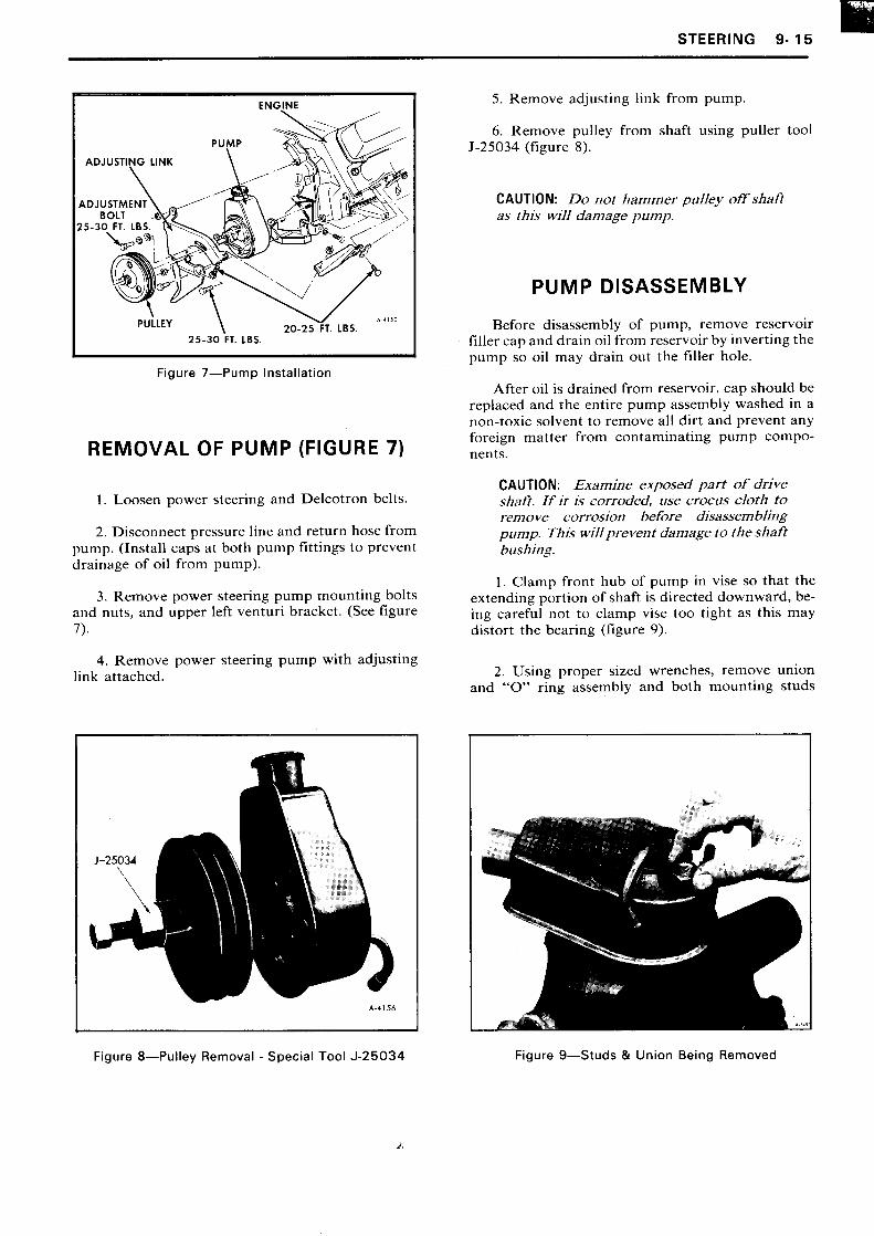
Figure 7-Pump Installation
REMOVAL OF PUMP (FIGURE 7)
1 . Loosen power steering and Delcotron belts.
2 . Disconnect pressure line and return hose frompump. (Install caps at both pump fittings to preventdrainage of oil from pump).
3. Remove power steering pump mounting boltsand nuts, and upper left venturi bracket . (See figure7) .
4. Remove power steering pump with adjustinglink attached .
Figure 8-Pulley Removal - Special Tool J-25034
STEERING
9- 1 5
5. Remove adjusting link from pump .
6. Remove pulley from shaft using puller toolJ-25034 (figure 8) .
CAUTION : Do not hammer pulley offshaftas this will damage pump.
PUMP DISASSEMBLY
Before disassembly of pump, remove reservoirfiller cap and drain oil from reservoir by inverting thepump so oil may drain out the filler hole .
After oil is drained from reservoir, cap should bereplaced and the entire pump assembly washed in anon-toxic solvent to remove all dirt and prevent anyforeign matter from contaminating pump compo-nents.
CAUTION : Examine exposed part of driveshaft. If it is corroded, use crocus cloth toremove corrosion before disassemblingpump. This willpreventdamage to the shaftbushing.
1 . Clamp front hub of pump in vise so that theextending portion of shaft is directed downward, be-ing careful not to clamp vise too tight as this maydistort the bearing (figure 9) .
2. Using proper sized wrenches, remove unionand "O" ring assembly and both mounting studs
Figure 9-Studs & Union Being Removed
9- 1 6
STEERING
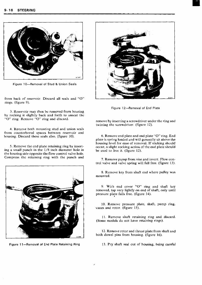
Figure 10-Removal of Stud & Union Seals
from back of reservoir. Discard all seals and "O"rings. (figure 9) .
3 . Reservoir may then be removed from housingby rocking it slightly back and forth to unseat the"O" ring. Remove "O" ring and discard.
4. Remove both mounting stud and union sealsfrom counterbored spaces between reservoir andhousing. Discard these seals also . (figure 10).
5. Remove the end plate retaining ring by insert-ing a small punch in the 1/8 inch diameter hole inthe housing side opposite the flow control valve hole .Compress the retaining ring with the punch and
Figure 1 1-Removal of End Plate Retaining Ring
Figure 12-Removal of End Plate
remove by inserting a screwdriver under the ring andtwisting the screwdriver. (figure 12).
6. Remove end plate and end plate "O" ring . Endplate is spring loaded and will generally sit above thehousing level for ease of removal . If sticking shouldoccur, a slight rocking action of the end plate shouldbe used to free it . (figure 12).
7. Remove pump from vise and invert . Flow con-trol valve and valve spring will fall free . (figure 13).
8 . Remove key from shaft end where pulley wasmounted.
9. With end cover "O" ring and shaft keyremoved, tap very lightly on end of shaft, only untilpressure plate falls free . (figure 14) .
10 . Remove pressure plate, shaft, pump ring,vanes and rotor. (figure 15).
11 . Remove shaft retaining ring and discard.(Some models do not have retaining rings) .
12 . Remove rotor and thrust plate from shaftandboth dowel pins from housing. (figure 16).
13 . Pry shaft seal out of housing, being careful
Figure 13-Removal of Relief Valve
not to damage the housing bore ; discard the shaftseal .
CLEANING AND INSPECTION
Carefully clean all pump parts in non-toxic clean-ing solvent. Replace any damaged or worn parts .
Figure 14-Tapping Shaft to Unseat Pressure Plate
STEERING
9- 1 7
Figure 15-Removal of Shaft, Pressure Plate, PumpRing, Vanes and Rotor
1 . Inspect flow control valve assembly for scoremarks, wear, burrs, or other damage .
2. Inspect castings for cracks or other visual evi-dences of damage . Check machined surfaces, espe-cially mating surfaces on "O" ring seats, forscratches or burrs that might permit leaks. Examine
Figure 16-Removing Dowel Pins From Housing
9- 1 8
STEERING
the V-shaped notches at edges of discharge ports onpressure plate. These notches must be clean and un-damaged if pump noise is to be avoided, as theycushion the hydraulic shock when each vane passesthe port.
3 . Inspect pump ring end surfaces for scoremarks.
NOTE : Because pump ring is treated, it leaves adull gray-black finish on wear surface. Wavygrain appearance inside pump ring is normal .
4 . Inspect pump shaft for score marks, excessivewear, or damage-particularly at splines, at keyway,and at bearing and seal surfaces . Separate and inspect rotorand vanes for wear and general condition.
5 . Inspect shaft bushing in pump housing. Re-place pump housing if bushing is scored or exces-sively worn .
6 . If any internal parts are found to be worn ordamaged, flush steering gear or disassemble gear andclean internal parts.
Figure 17-Installing Shaft Seal
ASSEMBLY OF PUMP1 . Install new pump shaft seal using seal protec-
tor J-22616 and seal installer J-7728 or a 1 inchsocket with an arbor press or hammer (figure 17).
CAUTION : DO not use any more force thannecessary to seat the seal.
2 . Lubricate new pressure plate "O" ring withPower Steering Fluid, and install in third groovefrom rear of housing.
3 . Clamp end hub of housing in vise in sameposition as before and insert both dowel pins . (figure16) .
CAUTION : Do not over tighten . The vice-damage to the bearing could occur.
4 . Insert shaft through thrust plate androtor, andinstall new snap ring on shaft. Open the snap ringjust enough to slide over the end of shaft. (Rotormust have counter sunk side toward thrust plate) .(figure 18).
5. Insert shaft in housing, making sure thrustplate slides properly on dowel pins .
6. Install pump ring on dowel pins with the arrowtoward rear of housing (figure 19).
7. Install all ten vanes in rotor slots with roundededge of vanes outward (figures 3 and 20). Vanesshould slide freely .
8. Lubricate pressure plate with Power SteeringFluid to protect pressure plate "O" ring .
Figure 18-Shaft With Thrust Plate and Rotor
Figure 19-Pump Ring Showing Arrow
9 . Install pressure plate on dowel pins with circu-lar depression for spring toward rear of housing .Pressure plate must be pressed about 1/16 inch overthe "O" ring to seat (figure 21) .
10 . Lubricate new end plate "O" ring with PowerSteering Fluid and install in second groove from rearof housing .
Figure 20-Replacement of Pump Vanes
STEERING
9- 1 9
Figure 21-Installing Pressure Plate
11 . Install end plate spring in groove provided inpressure plate (figure 12) .
12 . Lubricate end plate with Power SteeringFluid to protect "O" ring and press into housing withan arbor press (figure 22) . Depress only far enoughto enable retaining ring to seat properly in groove .
Figure 22-Installation of End Plate Retaining Spring
9- 20
STEERING
13 . Install end plate retaining ring and releasearbor press.
14 . Place flow control valve spring in hole firstand then insert flow control valve with screened endtoward front of housing.
15 . Install new stud seals and union seals in coun-ter sunk holes, and lubricate with Power SteeringFluid and install new reservoir "O" ring on housing(figure 10).
16 . Lubricate inside edge of reservoir with PowerSteering Fluid and install on housing. Align holes atthe same time.
17 . Insert both stud bolts and tighten (25-40 ft .lb .) (figure 9) .
18 . Install new "O" ring on union and lubricatewith Power Steering Fluid. Make sure "O" ring is inthe groove next to the head hex . Insert union in flowcontrol valve hole in back of reservoir and tighten(25-40 ft. lbs.) (figure 9) .
19 . Install key in shaft end. Support the shaft onthe opposite side of the key way and lightly tap thekey into place with plastic hammer.
PUMP SHAFT OIL SEALREPLACEMENT
(WITHOUT DISASSEMBLINGPUMP)
The pump shaft oil seal can be replaced withoutdisassembling the pump as follows :
1 . Remove the pulley as previously described .Bend a piece of .005 inch shim stock (approximately2-1/2 inches long) into a cylindrical shape, then pushthe shim stock past seal until it bottoms in pumpbody .
CAUTION : The use ofshim stock around thepump shaft will prevent damage to the ma-chined surfaces ofthe shaft when removingseal.
2. Cut metal body of seal with a small chisel .
3. Tear metal body approximately 1 inch withdiagonals. Force an awl between the pump body andthe OD of seal to collapse the seal, then pry seal frompump body . Remove shim stock.
4. Apply special seal lubricant No. 1050169 orequivalent to the sealing lip of a new seal, then installseal over pump shaft with metal side of seal out-board.
5. Slide Tool J-7132-2 over pump shaft, thendrive seal into pump body.
6. Install pump pulley .
INSTALLATION OF PUMP
(FIGURE 7)
1 . Install adjusting link on pump .
2. Draw pulley on shaft using Tool J-25033 .
CAUTION : Do not hammerpulley on, as thiswill damage internalpump parts (figure 23).
3 . Install pump assembly on engine and securewith bolts and nuts (torque to 25-30 ft . lbs .) andinstall venturi bracket (torque to 20-25 ft . lbs.)
4 . Connect and tighten hose fittings to 30-40 foot-pounds .
5 . Fill reservoir with fluid. Bleed pump by turn-ing pulley backward (counterclockwise as viewedfrom front) until air bubbles cease to appear .
6. Install pump belts over pulley .
Figure 23-Pulley Installation - Special Tool J-25033
7 . Move pump until belts are tight, then tightenadjusting screws . Do not pry on reservoir or pull onfiller neck .
8 . Adjust belts. (Refer to ADJUSTMENTS).
9 . Bleed system . (Refer to FLUID LEVEL underADJUSTMENTS) .
SERVICING OF THE FLOWCONTROL VALVE
(WITHOUT REMOVING PUMPASSEMBLY FROM VEHICLE)
REMOVAL1 . Disconnect high pressure hose from pump un-
ion and drain oil.
2. Remove union and withdraw flow controlvalve and spring with a magnet .
INSPECTION1 . Flow control valve must slide freely in housing
bore . If sticking occurs, check for dirt or burrs.
2. Check cap screw in the end of valve for loose-ness ; if loose, tighten, being careful not to damagemachined surfaces .
3 . If the flow control plunger is suspected of be-ing faulty, install new valve. This is serviced as a unitand is factory calibrated .
INSTALLATIONTo install, reverse the "Removal" procedure and
install a new "O" ring seal on the union .
ADJUSTMENTS
FLUID LEVEL1 . Run engine until Power Steering Fluid reaches
normal operating temperature, approximately170°F., then shut engine off. Remove reservoir fillercap and check oil level on dipstick .
2. If oil level is low, add Power Steering Fluid toproper level on dipstick and replace filler cap.
NOTE : When adding or making a complete fluidchange, always use special power steering fluidavailable from servicing parts warehouses .
BELT ADJUSTMENT
ADJUSTING BELT TENSION
STEERING
9- 21
3. When checking fluid level after the steeringsystem has been serviced, air must be bled from thesystem . Proceed as follows:
a. With wheels turned all the way to the left,add powersteering fluid to "Cold" mark on dipstick .
b . Start engine, run at fast idle, and recheckfluid level. Add fluid if necessary to "Cold" mark ondipstick .
c. Bleed system by turning wheels from sideto side without hitting stops. Maintain fluid level justabove internal pump casting. Fluid with air in it willhave a cloudy appearance . This air must be elimi-nated from fluid before normal steering action can beobtained .
d. Return wheels to center position and con-tinue to run engine for two or three minutes thenshut engine off.
e. Road test car to make sure steering func-tions normally and is free from noise.
f. Recheck fluid level as described in steps 1and 2, making sure fluid level is between "Cold" and"Hot" marks on dipstick after the system has stabil-ized at its normal operating temperature.
When adjusting a power steering pump belt,never pry against the pump reservoir or pull againstthe filler neck . To increase belt tension move thepump outwardby prying against the bracket pry lugsor against the pump housing casting extension di-rectly behind the pump drive pulley .
A belt that has been previously tensioned is con-sidered to be a used belt and should be tightened to70 to 80 pounds . A belt that has never been tensionedis considered to be a new belt and should be tight-ened to 110 to 140 pounds .
Place belt tension gauge (Borroughs Tool BT-33-73F) or equivalent midway between the pulleys ondrive belt being checked. If the belt tension is incor-rect proceed as follows:
1 . When power steering pump is driven by a sin-gle belt.
a. Loosen the pump attaching bolts and ad-just the belt to correct tension by moving the pumpoutward, away from the engine .
9- 22
STEERING
b. Snug all pump mounting bolts and removepry bar.
c. Tighten all pump mounting bolts to speci-fied torque .
d. Check belt tension and remove the belttension gage .
2 . When the power steering pump pulley is drivenby one primary belt and is used as an idler for asecond belt driving some other auxiliary:
a. Follow same checking and adjusting proce-dure for the primary power steering pump drive beltas for 1 above.
GENERAL INFORMATION
The integral power steering gear has an opencenter, rotary type, three-way control valve, whichdirects oil to either side of the rack piston . The rackpiston converts hydraulic power into mechanicaloutput . The steering gear is mounted on the leftframe rail by four mounting bolts. The steering shaftis joined to the steering gear through a flexible cou-pling, which reduces the transmission of hydraulicnoise to the steering wheel.
A constant displacement pump provides hydrau-lic pressure for the steering system . The pump is apulley driven vane type having an oil reservoir,which is part of the pump . It is attached to the frontof the engine by a bracket, and is belt driven from anengine crank shaft pulley .
- OPERATION
NEUTRAL (STRAIGHT AHEAD POSITION)
When turning effort is not being applied at thesteering wheel, the slots in the spool valve are posi-tioned so that oil entering the valve body from thehousing pressure port passes through the slots in thespool valve to the oil return port in the housing. Thechambers at both ends of the rack-piston and aroundthe pitman shaft are always full of oil, which acts asa cushion to absorb road shock so that they are nottransferred to the driver . In addition, this oil lubri-cates all the internal components of the gear.
STEERING GEAR
b. Recheck and adjust as necessary the pumpbelt tension after adjusting tension on belt driving theauxiliary.
OIL LINE FILTERThe steering gear oil is circulated by the pump
through the steering gear and the windshield wipermotor before it returns to the pump . In the line at thewindshield wiper motor is an oil filter . In the eventthat the oil pump is overhauled or replaced, this filtershould be replaced . For filter replacement proce-dure, refer to "Windshield Wiper Motor Filter Re-placement" of SECTION 1, BODY, HEATINGAND AIR CONDITIONING.
RIGHT TURNWhen the steering wheel is turned to the right,
the worm resists being turned because of the resist-ance offered by the front wheels . The valve body alsoresists turning because it is pinned to the worm .Driver force exerted at the steering wheel turns thestub shaft and spool valve a slight amount in relationto the valve body because ofthe twisting action of thetorsion bar. This slight amount of turning of thespool valve is sufficient to position the slots in thevalve body and spool valve for power assist .
The right turn slots in the spool valve are closedoff from the return (wide) slots in the valve body andopened more to the pressure (narrow) slots in thevalve body . The left turn slots in the spool valve areclosed off from the pressure slots in the valve bodyand opened more to the return slots in the valvebody .
Pressure immediately begins to build up againstthe lower end of the rack-piston, forcing it upwardto apply turning effort to the pitman shaft. The oilin the chamber at the upper end of the rack-pistonis then forced out through the valve body and spoolvalve through the oil return port to the pump reser-voir .
The instant the driver stops applying turning ef-fort to the steering wheel, the spool valve is forcedback into its neutral position by the torsion bar. Oilpressure on the lower end of the rack-piston thendecreases so that pressure is again equal on bothsides of the rack-piston, and the front wheels returnto the straight ahead position, when the vehicle ismoving .
Under normal driving conditions, oil pressuredoes not exceed 200 psi except when turning cornerswhere it does not ordinarily exceed 450 psi. Oil pressure, when parking, ranges from 900 to 1,300 psidepending upon road conditions and weight of thevehicle. The steering effort during normal driving,ranges from 1 to 2 lbs. and during parking from 2 to3-1/2 lbs. again depending upon road conditions .
A check valve located under the high pressureconnector seat hydraulically dampens the shocktransmitted to the steering gear when driving onwashboard roads.
LEFT TURNWhen the steering wheel is turned to the left, the
relationship between the spool valve slots and valvebody slots is again changed through twisting of thetorsion bar. Pressure immediately builds up againstthe upper end of the rack-piston, forcing it down-ward to apply turning effort to the pitman shaft. Theoil in the chamber at the lower end of the rack-pistonis forced out through the valve body and spool valveto the pump reservoir.
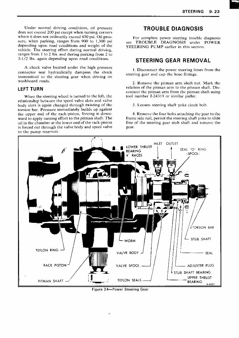
Figure 24-Power Steering Gear
STEERING
9- 23
TROUBLE DIAGNOSISFor complete power steering trouble diagnosis
see TROUBLE DIAGNOSIS under POWERSTEERING PUMP earlier in this section .
STEERING GEAR REMOVAL1 . Disconnect the power steering hoses from the
steering gear and cap the hose fittings .
2. Remove the pitman arm shaft nut. Mark therelation of the pitman arm to the pitman shaft. Dis-connect the pitman arm from the pitman shaft usingtool number J-24319 or similar puller .
3 . Loosen steering shaft yoke cinch bolt .
4 . Remove the four bolts attaching the gear to theframe side rail, permit the steering shaft yoke to slidefree of the steering gear stub shaft and remove thegear .
INLET OUTLETLOWER THRUST
SEAL "O" RINGBEARING4° RACES
SPOOL)
WORM
VALVE BODY
VALVE SPOOL
TEFLON SEALS
ADJUSTER PLUG
STUB SHAFT BEARINGUPPER THRUSTBEARING
A-4631
9- 24
STEERING
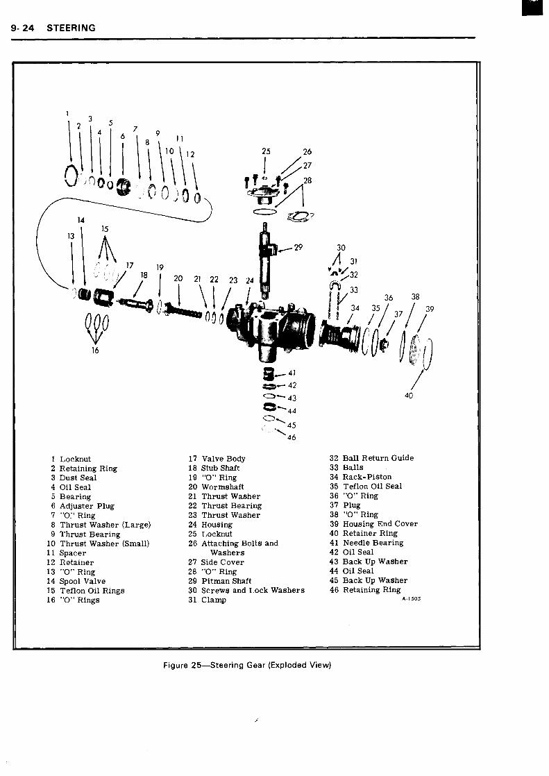
Figure 25-Steering Gear (Exploded View)
0'44,
4546
1 Locknut 17 Valve Body 32 Ball Return Guide2 Retaining Ring 18 Stub Shaft 33 Balls3 Dust Seal 19 "O" Ring 34 Rack-Piston4 Oil Seal 20 Wormshaft 35 Teflon Oil Seal5 Bearing 21 Thrust Washer 36 "O" Ring6 Adjuster Plug 22 Thrust Bearing 37 Plug7 "O_" Ring 23 Thrust Washer 38 "O" Ring8 Thrust Washer (Large) 24 Housing 39 Housing End Cover9 Thrust Bearing 25 Locknut 40 Retainer Ring10 Thrust Washer (Small) 26 Attaching Bolts and 41 Needle Bearing11 Spacer Washers 42 Oil Seal12 Retainer 27 Side Cover 43 Back Up Washer13 "O" Ring 28 "O" Ring 44 Oil Seal14 Spool Valve 29 Pitman Shaft 45 Back Up Washer15 Teflon Oil Rings 30 Screws and Lock Washers 46 Retaining Ring16 "O" Rings 31 Clamp A-1505
NOTE: If mounting threads are stripped, do notrepair . Replace housing.
STEERING GEAR OVERHAUL
Disassembly of the major components within thegear must be performed on a clean work bench. Thework area, tools, and parts must be kept clean at alltimes. Refer to Figures 24 and25 for parts nomencla-ture and location .
NOTE : Most service kits are purposely designedto replace not only a worn part, but also adjacentparts which should be replaced at the same time .To ensure an effective repair, use all parts sup-plied in the kit.
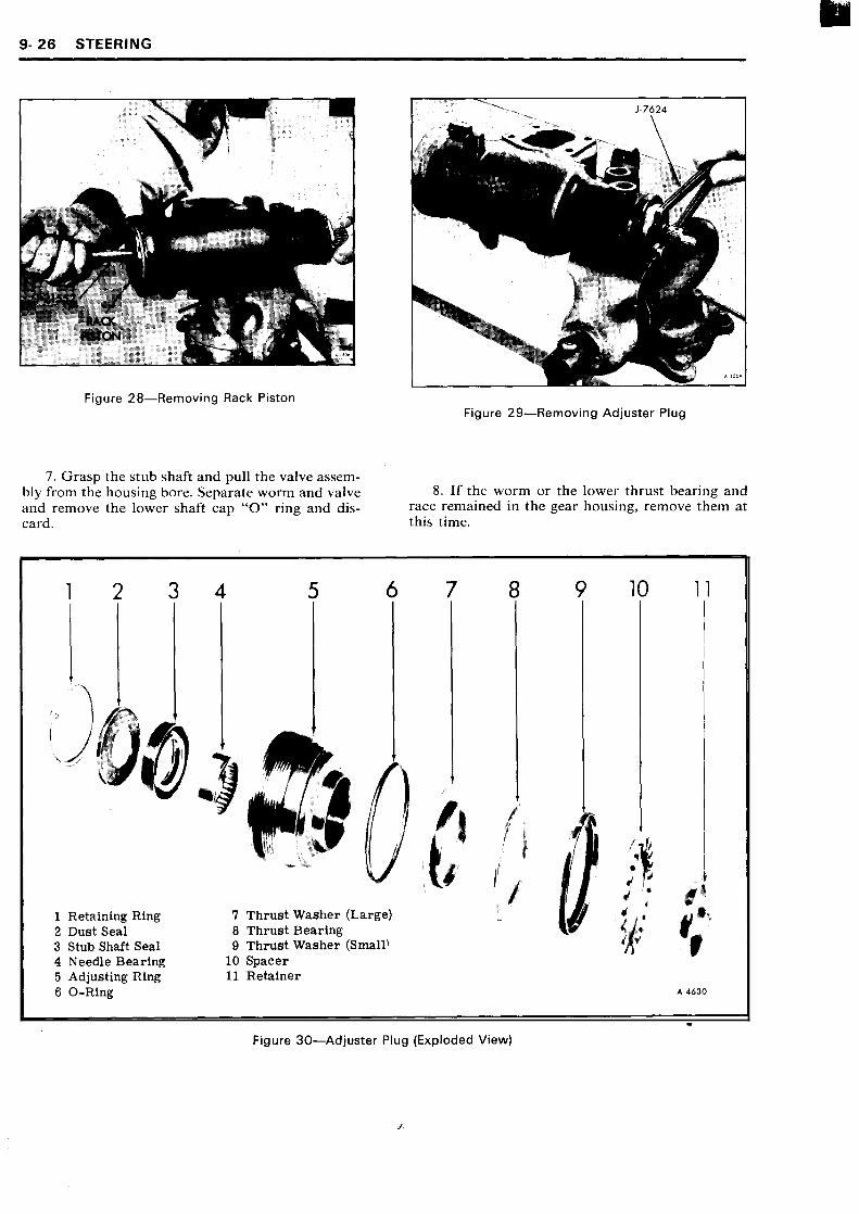
STEERING GEAR DISASSEMBLY1 . Rotate end cover retainer ring so that one end
of the ring is over the hole in the side of the housing.Force the end of the ring from its groove and removering (figure 26).
2. Turn the coupling flange counter-clockwiseuntil the rack-piston just forces end cover out ofhousing. Remove cover and discard "O" ring .
CAUTION : Do not turn stub shaft any fur-ther than absolutely necessary to removethe endplug, or balls from rack-piston andworm circuit may escape and lay loose in-side the rackpiston chamber.
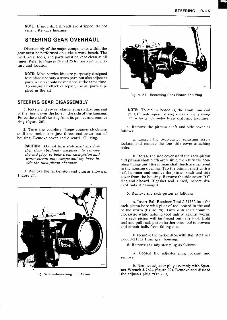
3 . Remove the rack-piston end plug as shown inFigure 27.
Figure 26-Removing End Cover
STEERING 9.25
Figure 27-Removing Rack-Piston End Plug
NOTE : To aid in loosening the aluminum endplug (female square drive) strike sharply using1 " or larger diameter brass drift and hammer.
4. Remove the pitman shaft and side cover asfollows:
a. Loosen the over-center adjusting screwlocknut and remove the four side cover attachingbolts.
b. Rotate the side cover until the rack-pistonand pitman shaft teeth are visible, then turn the cou-pling flange until the pitman shaft teeth are centeredin the housing opening. Tap the pitman shaft with asoft hammer and remove the pitman shaft and sidecover from the housing. Remove the side cover "O"ring and discard. If gasket seal is used, inspect, dis-card only if damaged.
5 . Remove the rack-piston as follows :
a. Insert Ball Retainer Tool J-21552 into therack-piston bore with pilot of tool seated in the endof the worm (figure 28). Turn stub shaft counterclockwise while holding tool tightly against worm.The rack-piston will be forced onto the tool . Holdtool and pull rack-piston farther onto tool to preventend circuit balls from falling out.
b. Remove the rack-piston with Ball RetainerTool J-21552 from gear housing.
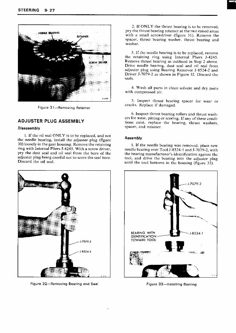
6. Remove the adjuster plug as follows:
a. Loosen the adjuster plug locknut andremove .
b. Remove adjuster plug assembly with Span-ner Wrench J-7624 (figure 29). Remove and discardthe adjuster plug "O" ring .
9- 2 6
STEERING
Figure 28-Removing Rack Piston
7. Grasp the stub shaft and pull the valve assem-bly from the housing bore . Separate worm and valveand remove the lower shaft cap "O" ring and dis-card .
1 Retaining Ring2 Dust Seal3 Stub Shaft Seal4 Needle Bearing5 Adjusting Ring6 O-Ring
2 3 4 5 6
7 Thrust Washer (Large)8 Thrust Bearing9 Thrust Washer (Smalh
10 Spacer11 Retainer
7 8 9 10 11
A-4630
Figure 30-Adjuster Plug (Exploded View)
Figure 29-Removing Adjuster Plug
8. If the worm or the lower thrust bearing andrace remained in the gear housing, remove them atthis time .
STEERING
9- 27
Figure 31-Removing Retainer
ADJUSTER PLUG ASSEMBLYDisassembly
1 . If the oil seal ONLY is to be replaced, and notthe needle bearing, install the adjuster plug (figure30) loosely in the gear housing. Remove the retainingring with Internal Pliers J-4245 . With a screw driver,pry the dust seal and oil seal from the bore of theadjuster plug being careful not to score the seal bore .Discard the oil seal .
Figure 32-Removing Bearing and Seal
2. If ONLY the thrust bearing is to be removed,pry the thrust bearing retainer at the two raised areaswith a small screwdriver (figure 31) . Remove thespacer, thrust bearing washer, thrust bearing andwasher .
3. If the needle bearing is to be replaced, removethe retaining ring using Internal Pliers J-4245 .Remove thrust bearing as outlined in Step 2 above.Drive needle bearing, dust seal and oil seal fromadjuster plug using Bearing Remover J-8524-2 andDriver J-7079-2 as shown in Figure 32. Discard theseals .
4. Wash all parts in clean solvent and dry partswith compressed air.
5 . Inspect thrust bearing spacer for wear orcracks . Replace if damaged.
6. Inspect thrust bearing rollers and thrust wash-ers for wear, pitting or scoring. If any of these condi-tions exist, replace the bearing, thrust washers,spacer, and retainer .
Assembly
1 . If the needle bearing was removed, place newneedle bearing over Tool J-8524-1 and J-7079-2, withthe bearing manufacturer's identification against thetool, and drive the bearing into the adjuster pluguntil the tool bottoms in the housing (figure 33) .
Figure 33-Installing Bearing
9- 28
STEERING
Figure 34-Installing Adjuster Plug Seal
CAUTION : Place a block of wood under theadjuster plug to protect it during driving ofthe bearing.
2. Place dust seal and a new stub shaft seal onTool J-8524-1 (face of seal with part number againstseal). Lubricate seal with Power Steering Fluid anddrive or press seals into adjuster plug until seated(figure 34). When properly installed the oil seal isunder the dust seal .
3 . Install retaining ring with Internal Pliers J-4245 .
4. Lubricate the thrust bearing assembly withPower Steering Fluid. Place the flanged thrust bear-ing race on the adjuster plug hub, then install theupper thrust bearing, small bearing race (flangededge up) and spacer (grooves of spacer away frombearing washer).
5 . Install bearing retainer on the adjuster plug bycarefully tapping on the flat surface of the retainer(figure 35).
CAUTION : The projections must not extendbeyond the spacer when the retainer isseated to prevent interference with valvebody. The spacer must be free to rotate.
Disassembly
Figure 35-Install Retainer
VALVE AND STUB SHAFT ASSEMBLY
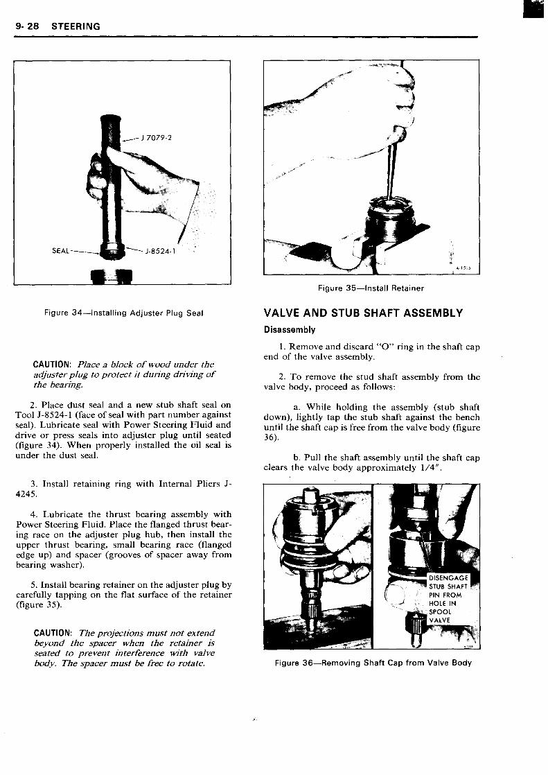
1 . Remove and discard "O" ring in the shaft capend of the valve assembly .
2. To remove the stud shaft assembly from thevalve body, proceed as follows:
a. While holding the assembly (stub shaftdown), lightly tap the stub shaft against the benchuntil the shaft cap is free from the valve body (figure36).
b. Pull the shaft assembly until the shaft capclears the valve body approximately 1/4" .
Figure 36-Removing Shaft Cap from Valve Body
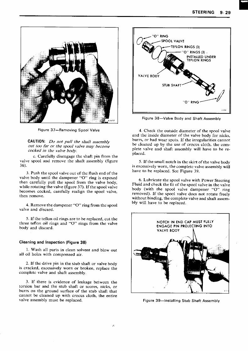
Figure 37-Removing Spool Valve
CAUTION : Do not pull the shaft assemblyout too far or the spool valve may becomecocked in the valve body.
c. Carefully disengage the shaft pin from thevalve spool and remove the shaft assembly (figure36).
3. Push the spool valve out of the flush end of thevalve body until the dampener "O" ring is exposedthen carefully pull the spool from the valve body,while rotating the valve (figure 37). If the spool valvebecomes cocked, carefully realign the spool valve,then remove .
4. Remove thedampener "O" ring from the spoolvalve and discard.
5 . If the teflon oil rings are to be replaced, cut thethree teflon oil rings and "O" rings from the valvebody and discard.
Cleaning and Inspection (Figure 38)
1 . Wash all parts in clean solvent and blow outall oil holes with compressed air.
2 . If the drive pin in the stub shaft or valve bodyis cracked, excessively worn or broken, replace thecomplete valve and shaft assembly .
3. If there is evidence of leakage between thetorsion bar and the stub shaft or scores, nicks, orburrs on the ground surface of the stub shaft thatcannot be cleaned up with crocus cloth, the entirevalve assembly must be replaced .
STEERING
9- 29
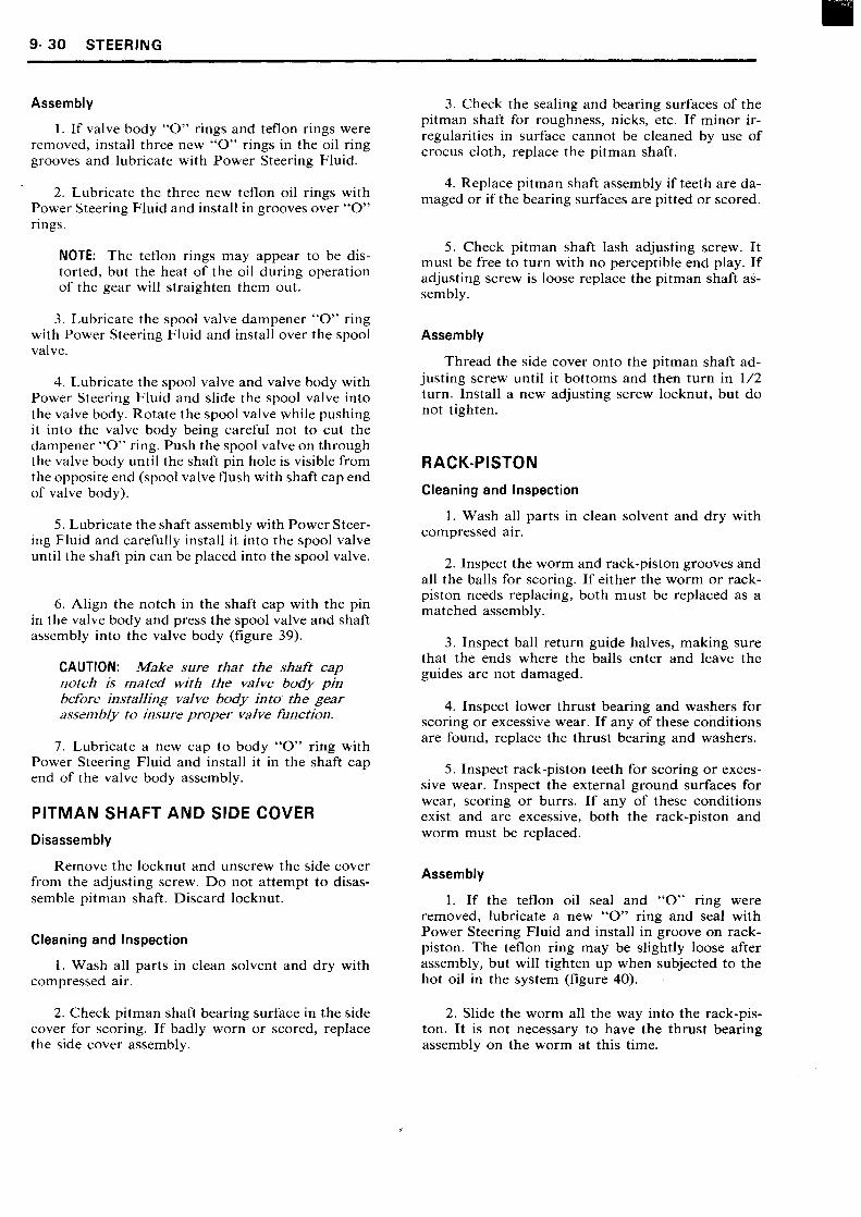
_.TEFLON RINGS (3)"O" RINGS (3) -
INSTALLED UNDERTEFLON RINGS
Figure 38-Valve Body and Shaft Assembly
4. Check the outside diameter of the spool valveand the inside diameter of the valve body for nicks,burrs, or bad wear spots. If the irregularities cannotbe cleaned up by the use of crocus cloth, the com-plete valve and shaft assembly will have to be re-placed .
5 . If the small notch in the skirt of the valve bodyis excessively worn, the complete valve assembly willhave to be replaced . See Figure 39.
6. Lubricate the spool valve with Power SteeringFluid and check the fit of the spool valve in the valvebody (with the spool valve dampener "O" ringremoved) . If the spool valve does not rotate freelywithout binding, the complete valve and shaft assem-bly will have to be replaced .
Figure 39-Installing Stub Shaft Assembly
9- 30
STEERING
Assembly
1 . If valve body "O" rings and teflon rings wereremoved, install three new "O" rings in the oil ringgrooves and lubricate with Power Steering Fluid.
2. Lubricate the three new teflon oil rings withPower Steering Fluid and install in grooves over "O"rings .
NOTE : The teflon rings may appear to be dis-torted, but the heat of the oil during operationof the gear will straighten them out.
3 . Lubricate the spool valve dampener "O" ringwith Power Steering Fluid and install over the spoolvalve.
4. Lubricate the spool valve and valve body withPower Steering Fluid and slide the spool valve intothe valve body . Rotate the spool valve while pushingit into the valve body being careful not to cut thedampener "O" ring . Push the spool valve on throughthe valve body until the shaft pin hole is visible fromthe opposite end (spool valve flush with shaft cap endof valve body).
5 . Lubricate the shaft assembly with Power Steer-ing Fluid and carefully install it into the spool valveuntil the shaft pin can be placed into the spool valve.
6. Align the notch in the shaft cap with the pinin the valve body and press the spool valve and shaftassembly into the valve body (figure 39).
CAUTION: Make sure that the shaft capnotch is mated with the valve body pinbefore installing valve body into the gearassembly to insure proper valve function.
7. Lubricate a new cap to body "O" ring withPower Steering Fluid and install it in the shaft capend of the valve body assembly .
PITMAN SHAFT AND SIDE COVERDisassembly
Remove the locknut and unscrew the side coverfrom the adjusting screw. Do not attempt to disas-semble pitman shaft . Discard locknut.
Cleaning and Inspection
1 . Wash all parts in clean solvent and dry withcompressed air.
2. Check pitman shaft bearing surface in the sidecover for scoring. If badly worn or scored, replacethe side cover assembly .
3 . Check the sealing and bearing surfaces of thepitman shaft for roughness, nicks, etc. If minor ir-regularities in surface cannot be cleaned by use ofcrocus cloth, replace the pitman shaft .
4. Replace pitman shaft assembly if teeth are da-maged or if the bearing surfaces are pitted or scored .
5 . Check pitman shaft lash adjusting screw. Itmust be free to turn with no perceptible end play . Ifadjusting screw is loose replace the pitman shaft as-sembly.
Assembly
Thread the side cover onto the pitman shaft ad-justing screw until it bottoms and then turn in 1/2turn . Install a new adjusting screw locknut, but donot tighten.
RACK-PISTON
Cleaning and Inspection
1 . Wash all parts in clean solvent and dry withcompressed air.
2. Inspect the worm and rack-piston grooves andall the balls for scoring. If either the worm or rack-piston needs replacing, both must be replaced as amatched assembly .
3 . Inspect ball return guide halves, making surethat the ends where the balls enter and leave theguides are not damaged .
4. Inspect lower thrust bearing and washers forscoring or excessive wear . If any of these conditionsare found, replace the thrust bearing and washers.
5 . Inspect rack-piston teeth for scoring or exces-sive wear . Inspect the external ground surfaces forwear, scoring or burrs. If any of these conditionsexist and are excessive, both the rack-piston andworm must be replaced .
Assembly
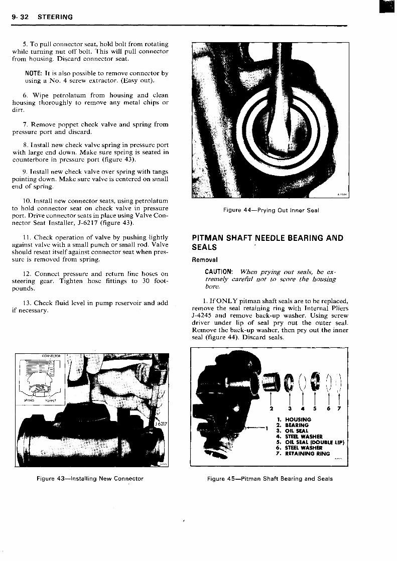
1 . If the teflon oil seal and "O" ring wereremoved, lubricate a new "O" ring and seal withPower Steering Fluid and install in groove on rackpiston . The teflon ring may be slightly loose afterassembly, but will tighten up when subjected to thehot oil in the system (figure 40).
2 . Slide the worm all the way into the rack-pis-ton. It is not necessary to have the thrust bearingassembly on the worm at this time .
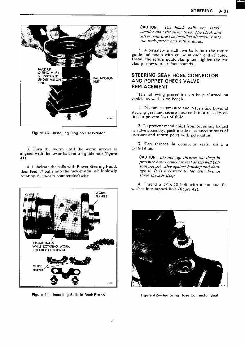
Figure 40-Installing Ring on Rack-Piston
3 . Turn the worm until the worm groove isaligned with the lower ball return guide hole (figure41) .
4. Lubricate the balls with Power Steering Fluid,then feed 17 balls into the rack-piston, while slowlyrotating the worm counterclockwise .
INSTALL BALLSWHILE ROTATING WORMCOUNTER CLOCKWISE
GUIDEHALVES
WORMFLANGE
A-1521
Figure 41-Installing Balls in Rack-Piston
STEERING
9- 31
CAUTION : The black balls are .0005"smaller than the silver balls. The black andsilver balls must be installed alternately intothe rackpiston and return guide.
5 . Alternately install five balls into the returnguide and retain with grease at each end of guide.Install the return guide clamp and tighten the twoclamp screws to six foot pounds.
STEERING GEAR HOSE CONNECTORAND POPPET CHECK VALVEREPLACEMENT
The following procedure can be performed onvehicle as well as on bench.
1 . Disconnect pressure and return line hoses atsteering gear and secure hose ends in a raised posi-tion to prevent loss of fluid .
2. To prevent metal chips from becoming lodgedin valve assembly, pack inside of connector seats ofpressure and return ports with petrolatum .
3 . Tap threads in connector seats, using a5/16-18 tap.
CAUTION : Do not tap threads too deep inpressure hose connector seat as tap will bot-tom poppet valve against housingand dam-age it. It is necessary to tap only two orthree threads deep .
4. Thread a 5/16-18 bolt with a nut and flatwasher into tapped hole (figure 42).
Figure 42-Removing Hose Connector Seat
9- 32
STEERING
5 . To pull connector seat, hold bolt from rotatingwhile turning nut off bolt . This will pull connectorfrom housing. Discard connector seat .
NOTE: It is also possible to remove connector byusing a No . 4 screw extractor. (Easy out) .
6. Wipe petrolatum from housing and cleanhousing thoroughly to remove any metal chips ordirt .
7. Remove poppet check valve and spring frompressure port and discard .
8 . Install new check valve spring in pressure portwith large end down . Make sure spring is seated incounterbore in pressure port (figure 43) .
9. Install new check valve over spring with tangspointing down . Make sure valve is centered on smallend of spring .
10 . Install new connector seats, using petrolatumto hold connector seat on check valve in pressureport . Drive connector seats in place using Valve Con-nector Seat Installer, J-6217 (figure 43) .
11 . Check operation of valve by pushing lightlyagainst valve with a small punch or small rod. Valveshould reseat itself against connector seat when pres-sure is removed from spring .
12 . Connect pressure and return line hoses onsteering gear . Tighten hose fittings to 30 foot-pounds .
13 . Check fluid level in pump reservoir and addif necessary .
Figure 43-Installing New Connector
Removal
Figure 44-Prying Out Inner Seal
PITMAN SHAFT NEEDLE BEARING ANDSEALS
CAUTION :
When prying out seals, be ex-tremely careful not to score the housingbore.
1 . If ONLY pitman shaft seals are to be replaced,remove the seal retaining_ ring with Internal PliersJ-4245 and remove back-up washer. Using screwdriver under lip of seal pry out the outer seal .Remove the back-up washer, then pry out the innerseal (figure 44). Discard seals.
2 3 4 5 6 7
1 . HOUSING2. BEARING3 . OIL SEAL4 . STEEL WASHER5. OIL SEAL (DOUBLE LIP)6 . STEEL WASHER7. RETAINING RING
Figure 45-Pitman Shaft Bearing and Seals
2. If pitman shaft needle bearing replacement isnecessary, remove with Tool J-6278 . Since this bear-ing is shouldered, it must be pressed out of the pit-man shaft end of the housing.
Assembly
1 . Thoroughly clean all parts (figure 45) and lu-bricate with Power Steering Fluid.
2 . Install pitman shaft needle bearing on BearingInstaller J-22407, with shoulder on bearing againsttool . Position bearing and tool in housing and pressbearing into housing until bottom edge of bearing isflush with the inner housing bore surface (figure 46).
CAUTION : Do not drive the bearing furtherinto the housing after removing Tool J-22407, since damage to the bearing wouldresult.
3 . Lubricate the lips of the oil seals with PowerSteering Fluid.
4. Install the pitman shaft oil seals as follows:
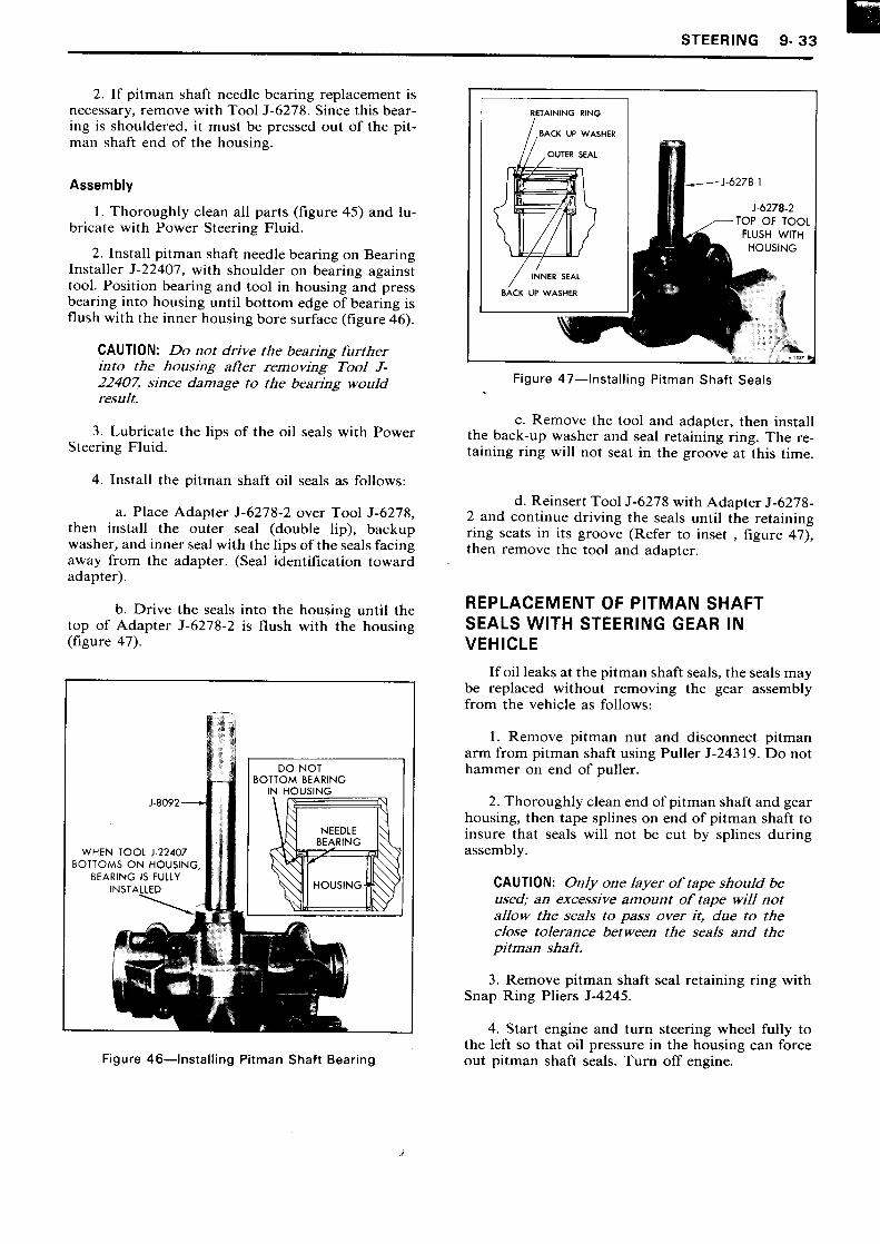
a. Place Adapter J-6278-2 over Tool J-6278,then install the outer seal (double lip), backupwasher, and inner seal with the lips of the seals facingaway from the adapter. (Seal identification towardadapter) .
b. Drive the seals into the housing until thetop of Adapter J-6278-2 is flush with the housing(figure 47).
Figure 46-Installing Pitman Shaft Bearing
STEERING
9- 33
Figure 47-Installing Pitman Shaft Seals
c. Remove the tool and adapter, then installthe back-up washer and seal retaining ring . The re-taining ring will not seat in the groove at this time .
d. Reinsert Tool J-6278 with Adapter J-6278-2 and continue driving the seals until the retainingring seats in its groove (Refer to inset , figure 47),then remove the tool and adapter.
REPLACEMENT OF PITMAN SHAFTSEALS WITH STEERING GEAR INVEHICLE
If oil leaks at the pitman shaft seals, the seals maybe replaced without removing the gear assemblyfrom the vehicle as follows:
1 . Remove pitman nut and disconnect pitmanarm from pitman shaft using Puller J-24319 . Do nothammer on end of puller .
2. Thoroughly clean end of pitman shaftand gearhousing, then tape splines on end of pitman shaft toinsure that seals will not be cut by splines duringassembly .
CAUTION : Only one layer oftape should beused; an excessive amount of tape will notallow the seals to pass over it, due to theclose tolerance between the seals and thepitman shaft.
3 . Remove pitman shaft seal retaining ring withSnap Ring Pliers J-4245 .
4. Start engine and turn steering wheel fully tothe left so that oil pressure in the housing can forceout pitman shaft seals. Turn off engine .
9- 34
STEERING
CAUTION :
Use suitable container to catchoil forced out of gear. This method ofremoving the pitman shaft seals is recom-mended, as it eliminates the possibility ofscoring the housing while attempting topryseals out.
5 . Inspect seals for damage to rubber covering onO.D . If O.D. appears scored, inspect housing forburrs and remove before attempting new seal instal-lation . Check seal surface of pitman shaft for rough-ness or pitting . If pitted replace pitman shaft .
6 . Clean the end of housing thoroughly so thatdirt will not enter housing with the installation of thenew seals .
7 . Lubricate the seals thoroughly with PowerSteering Fluid to install seals with Installer J-6219(figure 48) . Install the inner single lip seal first, thena back-up washer . Drive seal in far enough to provideclearance for the outer seal, back-up washer and re-taining ring . Make sure that the inner seal does notbottom on the counterbore . Install the outer doublelip seal and the second back-up washer in only farenough to provide clearance for the retaining ring .Install retaining ring .
8 . Fill pump reservoir to proper level with PowerSteering Fluid . Start engine and allow engine to idlefor at least three minutes without turning steeringwheel . Turn wheel to left and check for leaks . AddPower Steering Fluid as required .
9 . Remove tape and reconnect pitman arm .
Figure 48-Installing Pitman Shaft Seals
STUB VALVESHAFT BODY
LOWER THRUSTBEARING WASHERS
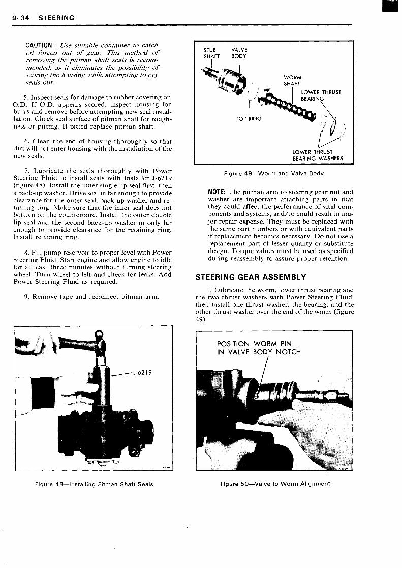
Figure 49-Worm and Valve Body
NOTE : The pitman arm to steering gear nut andwasher are important attaching parts in thatthey could affect the performance of vital com-ponents and systems, and/or could result in ma-jor repair expense . They must be replaced withthe same part numbers or with equivalent partsif replacement becomes necessary . Do not use areplacement part of lesser quality or substitutedesign . Torque values must be used as specifiedduring reassembly to assure proper retention .
STEERING GEAR ASSEMBLY1 . Lubricate the worm, lower thrust bearing and
the two thrust washers with Power Steering Fluid,then install one thrust washer, the bearing, and theother thrust washer over the end of the worm (figure49) .
Figure 50-Valve to Worm Alignment
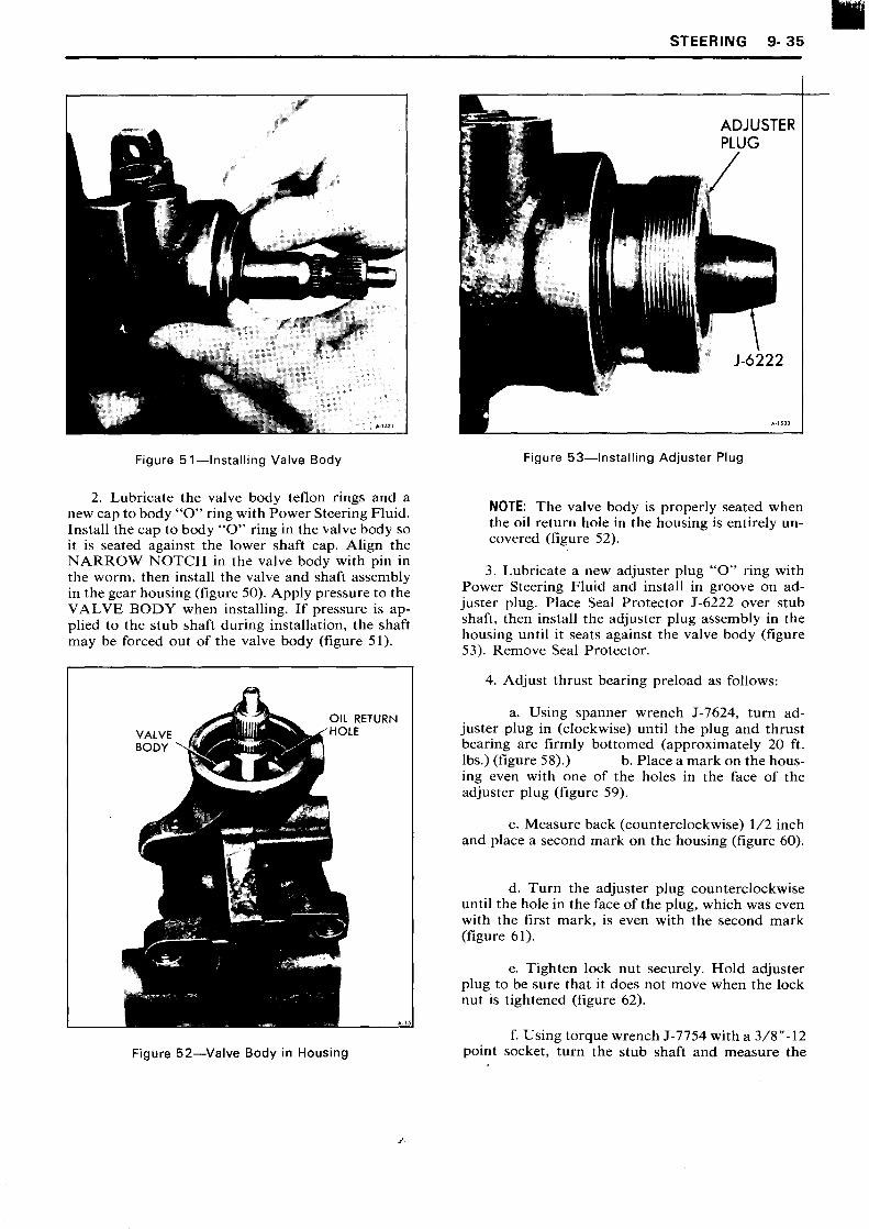
Figure 51-Installing Valve Body
2. Lubricate the valve body teflon rings and anew cap to body "O" ring with Power Steering Fluid.Install the cap to body "O" ring in the valve body soit is seated against the lower shaft cap. Align theNARROW NOTCH in the valve body with pin inthe worm, then install the valve and shaft assemblyin the gear housing (figure 50). Apply pressure to theVALVE BODY when installing . If pressure is ap-plied to the stub shaft during installation, the shaftmay be forced out of the valve body (figure 51) .
Figure 52-Valve Body in Housing
STEERING
9- 35
Figure 53-Installing Adjuster Plug
4. Adjust thrust bearing preload as follows:
NOTE : The valve body is properly seated whenthe oil return hole in the housing is entirely un-covered (figure 52).
3 . Lubricate a new adjuster plug "O" ring withPower Steering Fluid and install in groove on ad-juster plug . Place Seal Protector J-6222 over stubshaft, then install the adjuster plug assembly in thehousing until it seats against the valve body (figure53). Remove Seal Protector .
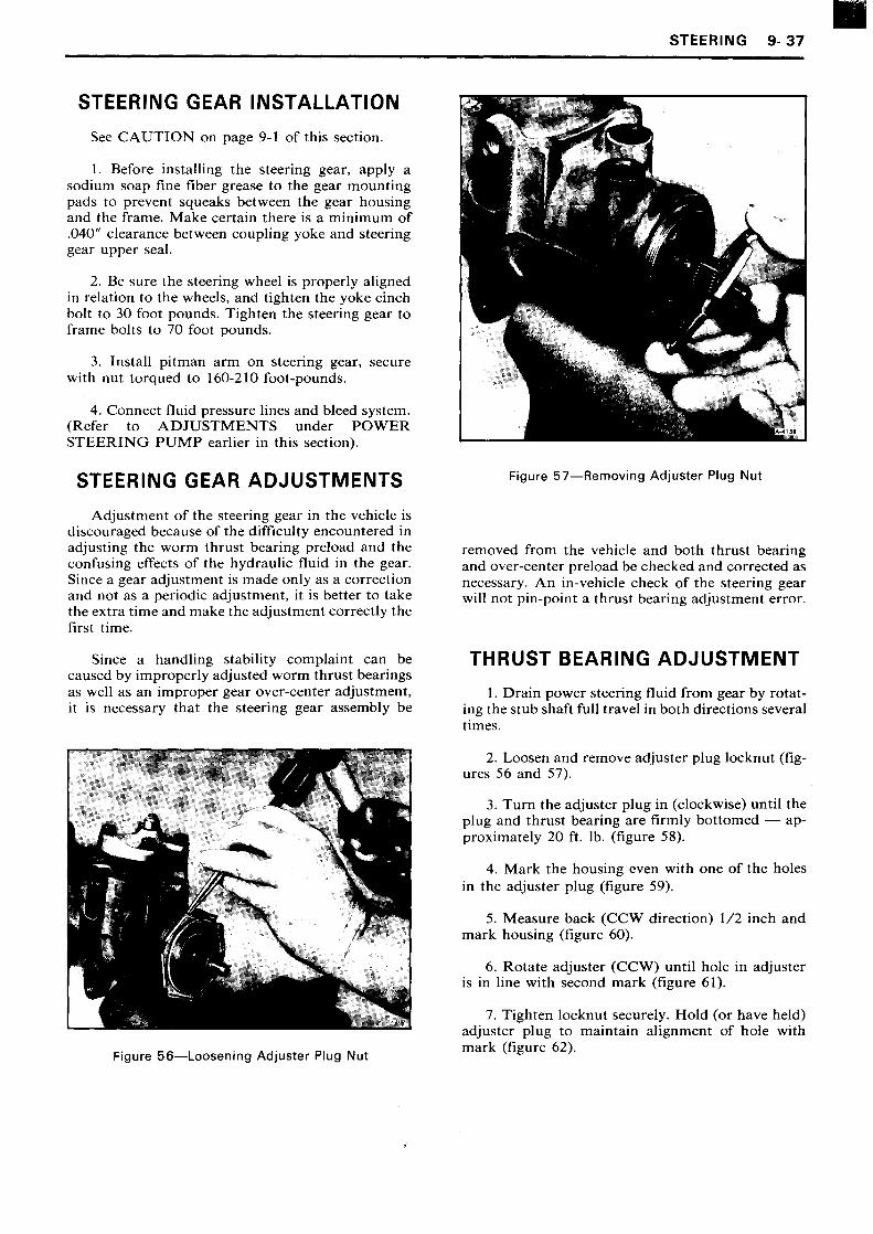
a. Using spanner wrench J-7624, turn ad-juster plug in (clockwise) until the plug and thrustbearing are firmly bottomed (approximately 20 ft .lbs.) (figure 58).)
b. Place a mark on the hous-ing even with one of the holes in the face of theadjuster plug (figure 59).
c. Measure back (counterclockwise) 1/2 inchand place a second mark on the housing (figure 60).
d. Turn the adjuster plug counterclockwiseuntil the hole in the face of the plug, which was evenwith the first mark, is even with the second mark(figure 61).
e. Tighten lock nut securely . Hold adjusterplug to be sure that it does not move when the locknut is tightened (figure 62).
f. Using torque wrench J-7754 with a 3/8"-12point socket, turn the stub shaft and measure the
9- 3 6
STEERING
Figure 54-Installing Rack-Piston
torque . Torque reading should be between 4 and 6 in .lbs. If torque is not within these specifications, loosenlock nut and turn the adjuster until the proper torqueis obtained . Retighten nut as described in 4e . Withadjuster secured in place, coat junction of dust sealand stub shaft with anhydrous calcium based grease(included with repair kits).
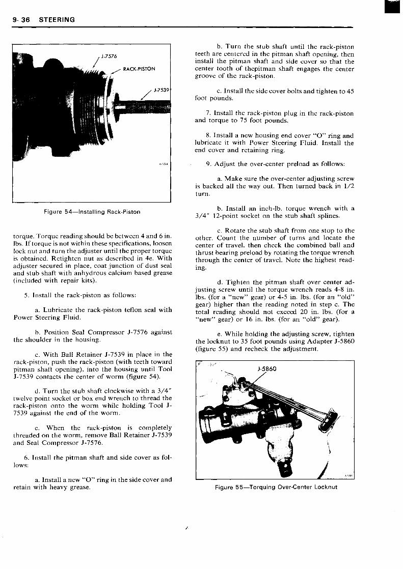
5. Install the rack-piston as follows:
a. Lubricate the rack-piston teflon seal withPower Steering Fluid.
b. Position Seal Compressor J-7576 againstthe shoulder in the housing .
c. With Ball Retainer J-7539 in place in therack-piston, push the rack-piston (with teeth towardpitman shaft opening), into the housing until ToolJ-7539 contacts the center of worm (figure 54).
d. Turn the stub shaft clockwise with a 3/4"twelve point socket or box end wrench to thread therack-piston onto the worm while holding Tool J-7539 against the end of the worm.
e. When the rack-piston is completelythreaded on the worm, remove Ball Retainer J-7539and Seal Compressor J-7576 .
6. Install the pitman shaft and side cover as fol-lows :
a. Install a new "O" ring in the side cover andretain with heavy grease .
b. Turn the stub shaft until the rack-pistonteeth are centered in the pitman shaft opening, theninstall the pitman shaft and side cover so that thecenter tooth of thepitman shaft engages the centergroove of the rack-piston.
c. Install the side cover bolts and tighten to 45foot pounds .
7. Install the rack-piston plug in the rack-pistonand torque to 75 foot pounds .
8. Install a new housing end cover "O" ring andlubricate it with Power Steering Fluid. Install theend cover and retaining ring .
9. Adjust the over-center preload as follows:
a. Make sure the over-center adjusting screwis backed all the way out. Then turned back in 1/2turn .
b. Install an inch-lb. torque wrench with a3/4" 12-point socket on the stub shaft splines.
c. Rotate the stub shaft from one stop to theother. Count the number of turns and locate thecenter of travel, then check the combined ball andthrust bearing preload by rotating the torque wrenchthrough the center of travel . Note the highest read-ing.
d. Tighten the pitman shaft over center ad-justing screw until the torque wrench reads 4-8 in .lbs. (for a "new" gear) or 4-5 in . lbs. (for an "old"gear) higher than the reading noted in step c. Thetotal reading should not exceed 20 in . lbs. (for a"new" gear) or 16 in . lbs. (for an "old" gear).
e. While holding the adjusting screw, tightenthe locknut to 35 foot pounds using Adapter J-5860(figure 55) and recheck the adjustment .
Figure 55-Torquing Over-Center Locknut
STEERING GEAR INSTALLATION
See CAUTION on page 9-1 of this section.
1 . Before installing the steering gear, apply asodium soap fine fiber grease to the gear mountingpads to prevent squeaks between the gear housingand the frame. Make certain there is a minimum of.040" clearance between coupling yoke and steeringgear upper seal .
2. Be sure the steering wheel is properly alignedin relation to the wheels, and tighten the yoke cinchbolt to 30 foot pounds . Tighten the steering gear toframe bolts to 70 foot pounds .
3. Install pitman arm on steering gear, securewith nut torqued to 160-210 foot-pounds.
4. Connect fluid pressure lines and bleed system.(Refer to ADJUSTMENTS under POWERSTEERING PUMP earlier in this section) .
STEERING GEAR ADJUSTMENTS
Adjustment of the steering gear in the vehicle isdiscouraged because of the difficulty encountered inadjusting the worm thrust bearing preload and theconfusing effects of the hydraulic fluid in the gear .Since a gear adjustment is made only as a correctionand not as a periodic adjustment, it is better to takethe extra time and make the adjustment correctly thefirst time .
Since a handling stability complaint can becaused by improperly adjusted worm thrust bearingsas well as an improper gear over-center adjustment,it is necessary that the steering gear assembly be
Figure 56-Loosening Adjuster Plug Nut
STEERING
9- 37
Figure 57-Removing Adjuster Plug Nut
removed from the vehicle and both thrust bearingand over-center preload be checked and corrected asnecessary. An in-vehicle check of the steering gearwill not pin-point a thrust bearing adjustment error.
THRUST BEARING ADJUSTMENT
1 . Drain power steering fluid from gear by rotat-ing the stub shaft full travel in both directions severaltimes.
2. Loosen and remove adjuster plug locknut (fig-ures 56 and 57).
3 . Turn the adjuster plug in (clockwise) until theplug and thrust bearing are firmly bottomed -ap-proximately 20 ft . lb . (figure 58).
4. Mark the housing even with one of the holesin the adjuster plug (figure 59).
5. Measure back (CCW direction) 1/2 inch andmark housing (figure 60).
6. Rotate adjuster (CCW) until hole in adjusteris in line with second mark (figure 61).
7. Tighten locknut securely . Hold (or have held)adjuster plug to maintain alignment of hole withmark (figure 62).
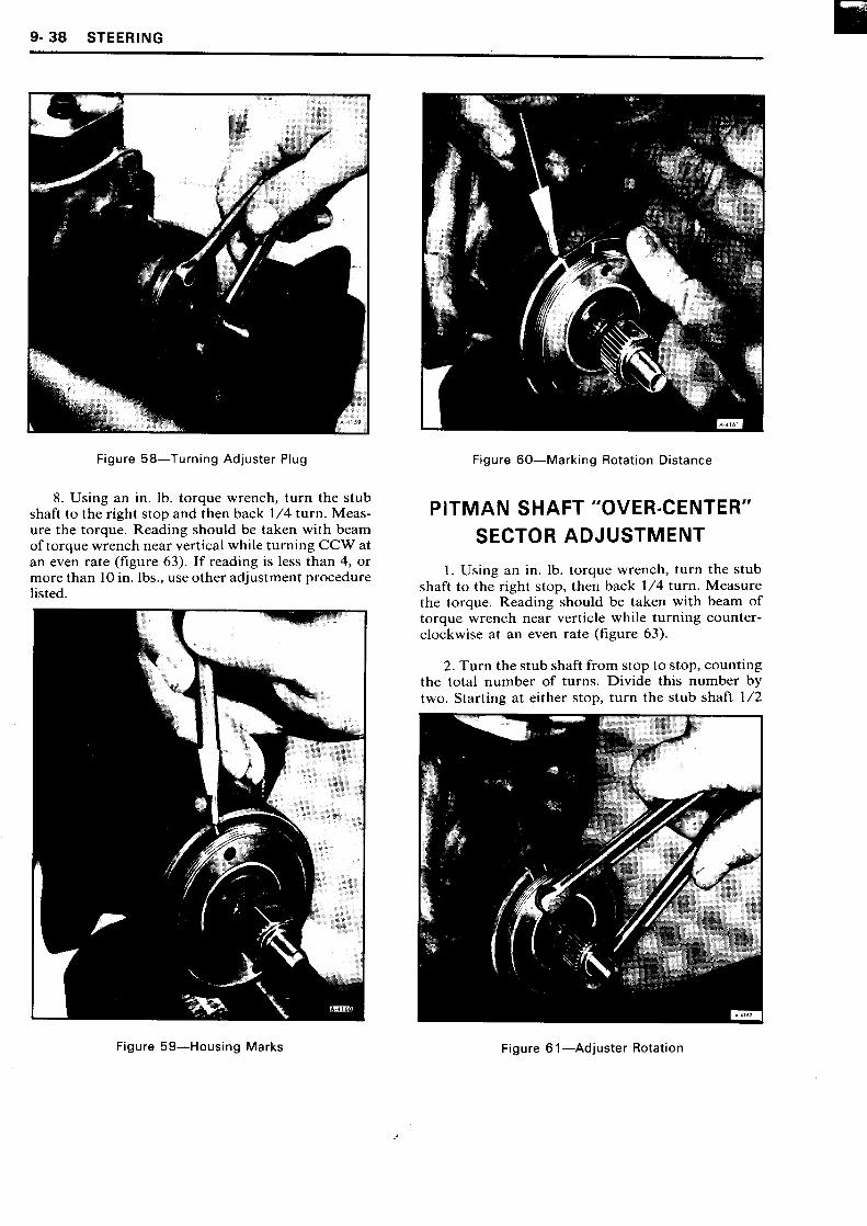
9- 38
STEERING
Figure 58-Turning Adjuster Plug
8 . Using an in . lb. torque wrench, turn the stubshaft to the right stop and then back 1/4 turn . Meas-ure the torque . Reading should be taken with beamoftorque wrench near vertical while turning CCW atan even rate (figure 63). If reading is less than 4, ormore than 10 in . lbs., use otheradjustment procedurelisted .
Figure 59-Housing Marks
Figure 60-Marking Rotation Distance
PITMAN SHAFT "OVER-CENTER"SECTOR ADJUSTMENT
1 . Using an in . lb. torque wrench, turn the stubshaft to the right stop, then back 1/4 turn . Measurethe torque . Reading should be taken with beam oftorque wrench near verticle while turning counter-clockwise at an even rate (figure 63).
2. Turn the stub shaft from stop to stop, countingthe total number of turns. Divide this number bytwo . Starting at either stop, turn the stub shaft 1/2
Figure 61-Adjuster Rotation
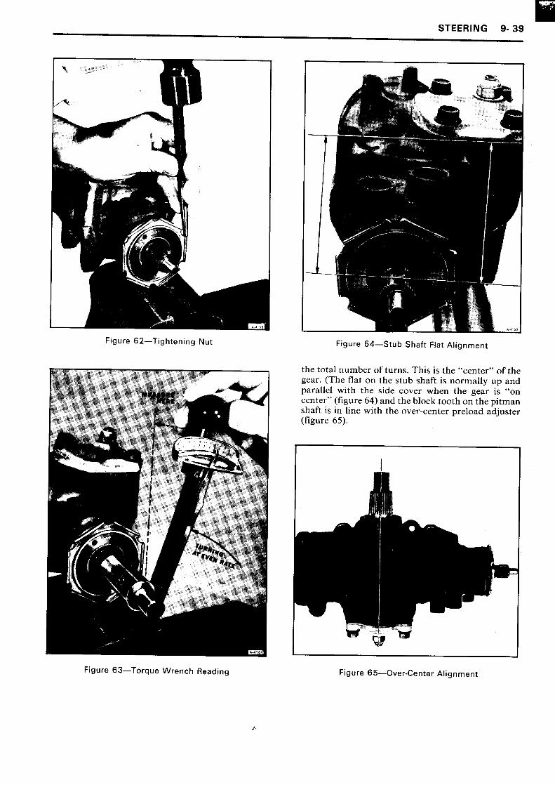
Figure 62-Tightening Nut
Figure 63-Torque Wrench Reading
STEERING
9- 39
Figure 64-Stub Shaft Flat Alignment
the total number of turns. This is the "center" of thegear. (The flat on the stub shaft is normally up andparallel with the side cover when the gear is "oncenter" (figure 64) and the block tooth on the pitmanshaft is in line with the over-center preload adjuster(figure 65).
Figure 65-Over-Center Alignment
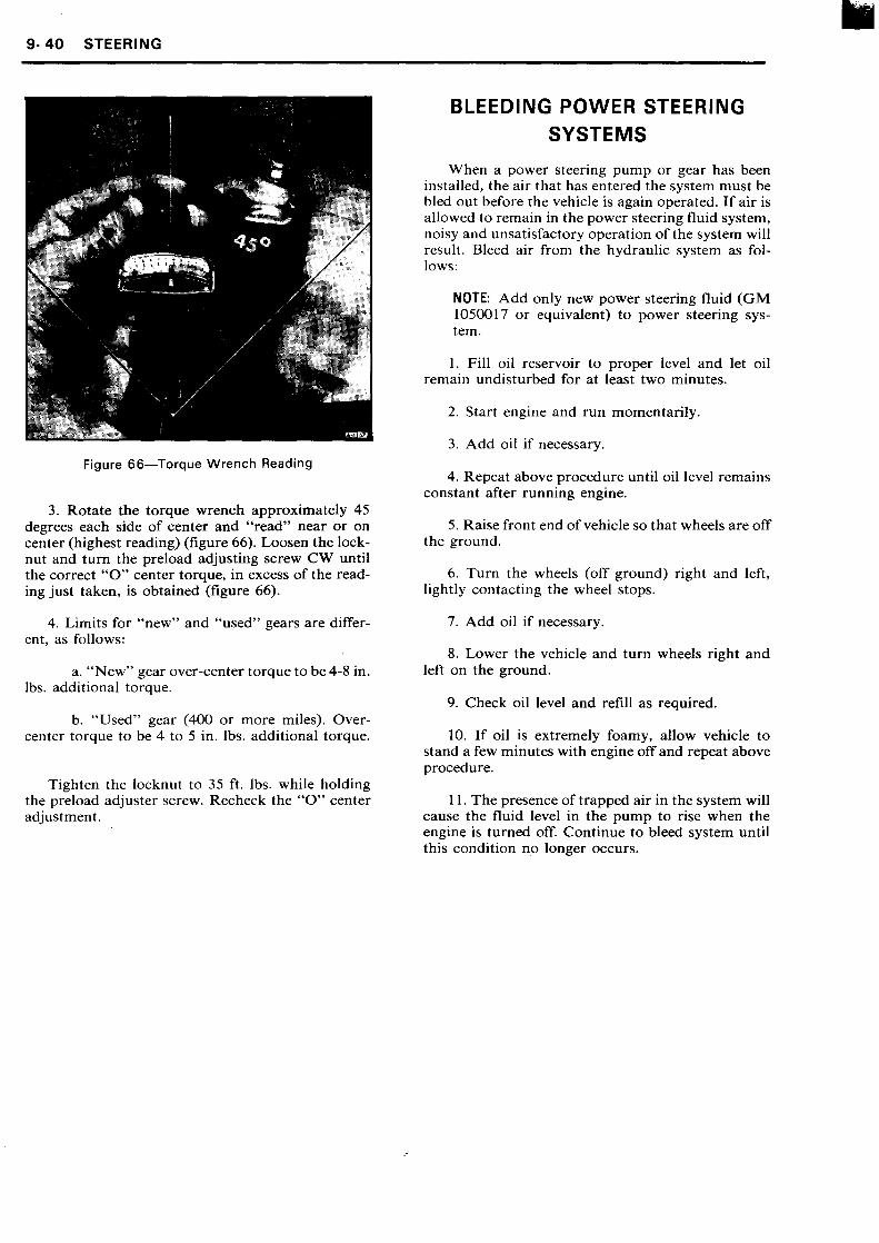
9- 40
STEERING
Figure 66-Torque Wrench Reading
3 . Rotate the torque wrench approximately 45degrees each side of center and "read" near or oncenter (highest reading) (figure 66). Loosen the locknut and turn the preload adjusting screw CW untilthe correct "O" center torque, in excess of the read-ing just taken, is obtained (figure 66).
4. Limits for "new" and "used" gears are differ-ent, as follows:
a. "New" gear over-center torque to be 4-8 in .lbs. additional torque .
b. "Used" gear (400 or more miles) . Over-center torque to be 4 to 5 in . lbs. additional torque .
Tighten the locknut to 35 ft. lbs. while holdingthe preload adjuster screw. Recheck the "O" centeradjustment .
BLEEDING POWER STEERINGSYSTEMS
When a power steering pump or gear has beeninstalled, the air that has entered the system must bebled out before the vehicle is again operated . If air isallowed to remain in the powersteering fluid system,noisy and unsatisfactory operation of the system willresult . Bleed air from the hydraulic system as fol-lows :
NOTE : Add only new power steering fluid (GM1050017 or equivalent) to power steering sys-tem .
1 . Fill oil reservoir to proper level and let oilremain undisturbed for at least two minutes.
2 . Start engine and run momentarily.
3 . Add oil if necessary.
4. Repeat above procedure until oil level remainsconstant after running engine .
5. Raise front end of vehicle so that wheels are offthe ground .
6. Turn the wheels (off ground) right and left,lightly contacting the wheel stops.
7. Add oil if necessary.
8. Lower the vehicle and turn wheels right andleft on the ground .
9. Check oil level and refill as required .
10 . If oil is extremely foamy, allow vehicle tostand afew minutes with engine offand repeat aboveprocedure.
11 . The presence of trapped air in the system willcause the fluid level in the pump to rise when theengine is turned off. Continue to bleed system untilthis condition no longer occurs .
CAUTION: Allcolumn fasteners are important attaching parts in that they couldaffect the performance of vital components andsystems, and/or could result inmajorrepair expense. They must be replaced with parts of the same part num-bers or with equivalent parts if replacement becomes necessary. Do not usereplacement parts oflesser quality or substitute design. Torque values must beused as specified during re-assembly to assure proper retention of these parts.
GENERAL INFORMATION AND
OPERATION
The function locking energy-absorbing steeringcolumn includes three important features in additionto the steering function :
I . The column is energy-absorbing, designedto compress up to 8.25 inches in a front-end collisionto minimize the possibility of injury to the driver ofthe vehicle.
11 . The ignition switch and lock are mountedconveniently on the column.
111. With the column mounted lock, the igni-tion, steering and gearshifting operation can belocked to inhibit theft of the vehicle.
The function locking energy-absorbing steeringcolumn assembly is used on all vehicles . When avehicle is being driven, the forward movement of thevehicle and the forward movement of the driver bothconstitute a form of kinetic energy . When a vehicleis involved in a frontal collision, the primary force(forward movement of the vehicle) is suddenlyhalted, while the secondary force (the driver) contin-ues its forward direction . A severe frontal collisiongenerally involves these two forces-the primary andthe secondary forces . Thesecondary impact occurswhen the driver is thrust forward onto the steeringwheel and column .
The function locking energy-absorbing column isdesigned to absorb these primary and secondaryforces to the extent that the severity of the secondaryimpact is reduced .
The tilt function locking columns are designedfor ease of entry and driver comfront . These columnshave six or seven different steering wheel angle posi-tions .
The tilt mechanism consists of an upper andlower steering shaft assembly with a universal jointbetween them . A support assembly is held to the
STEERING COLUMN
STEERING
9- 41
mast jacket by a lock plate, and a hearing housingassembly is positioned over .the upper steering shaftand secured to the support by two pivot pins . Twolock shoes are pinned to the housing assembly andengage a pin in the support assembly . When therelease lever is pulled up and the lock shoes disen-gage the support pin, the steering wheel is pushed upby a spring compressed between the support andhousing assemblies .
The operation of the lock is the same as in otherGM vehicles . To start the vehicle, you insert the keyin the lock, turn the unit clockwise to "start" and letthe switch return to the "on" position . The "off',"lock" and "accessory" positions are also the sameas in other GM vehicles When you engage theshift lever in "park" and lock the ignition, the steer-ing wheel locks and the gearshift locks.
The function locking energy-absorbing columnmay be easily disassembled and reassembled. Theserviceman should be aware that it is important thatonly the specified screws, bolts and nuts be used asdesignated and that they are tightened to their speci-fied torque . This precaution will insure the energyabsorbing action of the assembly . Overlength boltsshould not be used, as they may prevent a portion ofthe assembly from compressing under impact .Equally as important is correct torque of bolts andnuts . Care should be taken to assure that the bolts ornuts securing the column mounting bracket to theinstrument panel are torqued to the proper specifica-tion in order that the bracket will break away underimpact .
When the column is removed, special care mustbe taken in handling this assembly . Only the speci-fied wheel puller should be used . When the columnis removed from the vehicle, such actions as a sharpblow on the end of the steering shaft or shift lever,leaning on the column assembly, or dropping of theassembly could shear or loosen the plastic fastenersthat maintain column rigidity . It is, therefore, impor-tant that the removal and installation and the disas-sembly and reassembly procedures be carefullyfollowed when servicing the assembly .
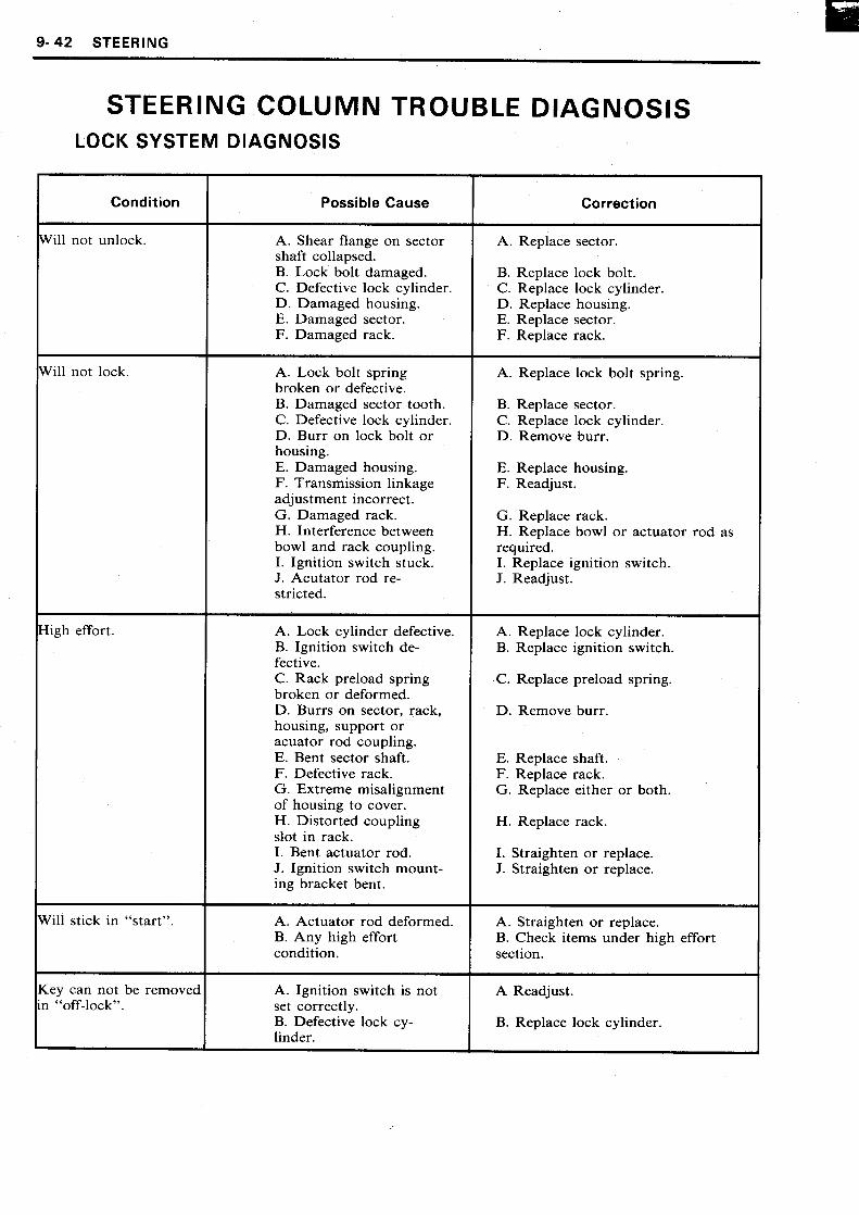
9- 42
STEERING
STEERING COLUMN TROUBLE DIAGNOSISLOCK SYSTEM DIAGNOSIS
Condition Possible Cause Correction
ill not unlock . A. Shear flange on sector A. Replace sector .shaft collapsed .B. Lock bolt damaged. B. Replace lock bolt .C. Defective lock cylinder . C. Replace lock cylinder .D. Damaged housing. D. Replace housing.E. Damaged sector . E. Replace sector.F. Damaged rack . F. Replace rack .
Will not lock . A. Lock bolt spring A. Replace lock bolt spring .broken or defective .B. Damaged sector tooth. B. Replace sector .C. Defective lock cylinder . C. Replace lock cylinder.D. Burr on lock bolt or D. Remove burr .housing.E. Damaged housing. E. Replace housing.F. Transmission linkage F. Readjust .adjustment incorrect .G. Damaged rack . G. Replace rack .H. Interference between H . Replace bowl or actuator rod asbowl and rack coupling . required .I . Ignition switch stuck. I . Replace ignition switch .J. Acutator rod re- J. Readjust .stricted .
High effort . A. Lock cylinder defective. A. Replace lock cylinder .B . Ignition switch de- B. Replace ignition switch .fective.C. Rack preload spring C. Replace preload spring .broken or deformed .D. Burrs on sector, rack, D. Remove burr .housing, support oracuator rod coupling .E. Bent sector shaft. E. Replace shaft.F. Defective rack . F. Replace rack .G. Extreme misalignment G. Replace either or both .of housing to cover.H. Distorted coupling H. Replace rack .slot in rack .I . Bent actuator rod. I. Straighten or replace.J. Ignition switch mount- J. Straighten or replace.ing bracket bent .
Will stick in "start". A. Actuator rod deformed . A. Straighten or replace.B. Any high effort B. Check items under high effortcondition . section.
Key can not be removed A. Ignition switch is not A Readjust .in "off-lock" . set correctly .
B. Defective lock cy- B. Replace lock cylinder .linder .
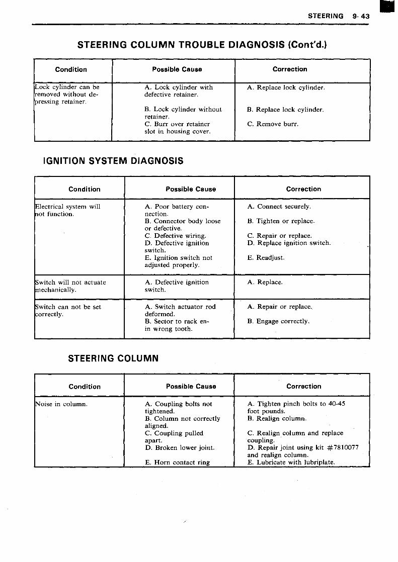
STEERING COLUMN TROUBLE DIAGNOSIS (Cont'd .)
IGNITION SYSTEM DIAGNOSIS
STEERING
9- 43
STEERING COLUMN
Condition Possible Cause Correction
Lock cylinder can be A. Lock cylinder with A. Replace lock cylinder .removed without de- defective retainer.pressing retainer .
B. Lock cylinder without B. Replace lock cylinder .retainer.C. Burr over retainer C. Remove burr .slot in housing cover.
Condition Possible Cause Correction
Electrical system will A. Poor battery con- A. Connect securely .of function . nection .
B . Connector body loose B. Tighten or replace.or defective .C. Defective wiring . C. Repair or replace.D. Defective ignition D. Replace ignition switch .switch .E. Ignition switch not E. Readjust .adjusted properly .
Switch will not actuate A. Defective ignition A. Replace.mechanically . switch .
Switch can not be set A. Switch actuator rod A. Repair or replace.correctly . deformed .
B. Sector to rack en- B. Engage correctly .in wrong tooth .
Condition Possible Cause Correction
Noise in column. A. Coupling bolts not A. Tighten pinch bolts to 40-45tightened . foot pounds .B. Column not correctly B. Realign column .aligned.C. Coupling pulled C. Realign column and replaceapart. coupling.D. Broken lower joint. D. Repair joint using kit #7810077
and realign column .E. Horn contact ring E. Lubricate with lubriplate.
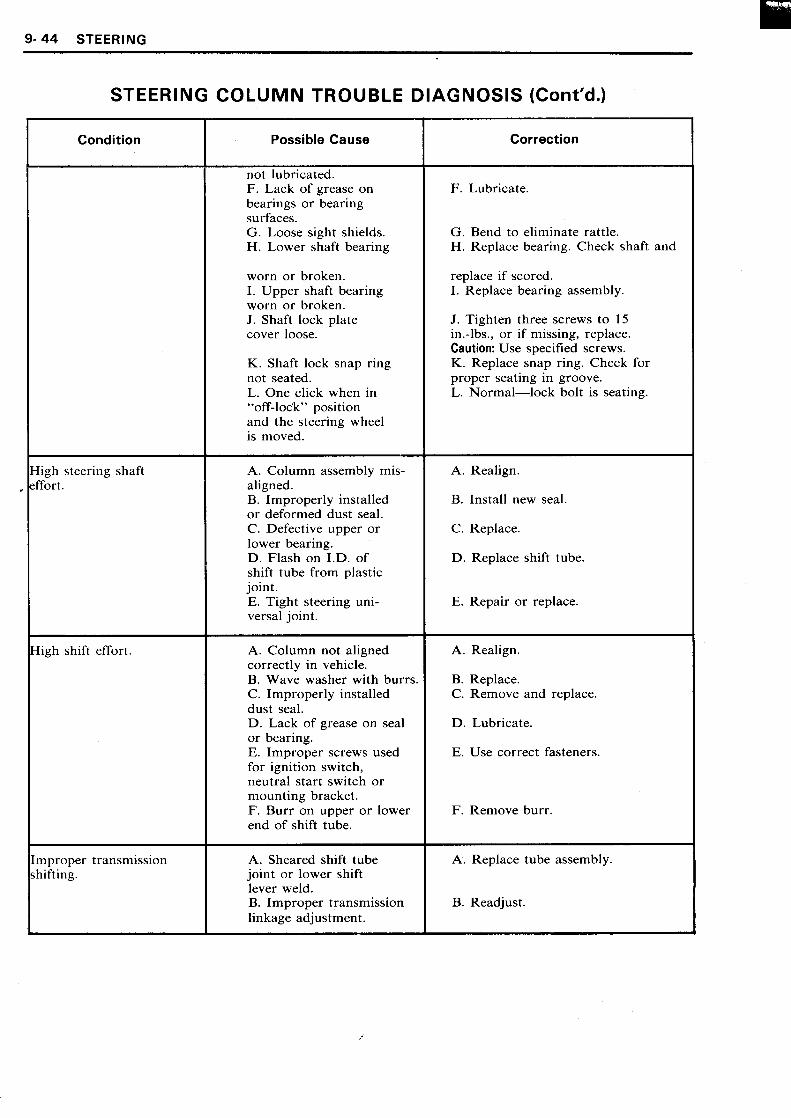
9- 44
STEERING
STEERING COLUMN TROUBLE DIAGNOSIS (Cont'd.)
Condition Possible Cause Correction
not lubricated .F. Lack of grease on F. Lubricate.bearings or bearingsurfaces .G. Loose sight shields. G . Bend to eliminate rattle .H. Lower shaft bearing H. Replace bearing. Check shaft and
worn or broken . replace if scored .I. Upper shaft bearing I. Replace bearing assembly .worn or broken .J. Shaft lock plate J. Tighten three screws to 15cover loose. in .-lbs., or if missing, replace.
Caution : Use specified screws.K. Shaft lock snap ring K. Replace snap ring . Check fornot seated. proper seating in groove .L. One click when in L. Normal-lock bolt is seating."off-lock" positionand the steering wheelis moved.
High steering shaft A. Column assembly mis- A. Realign.effort . aligned.
B. Improperly installed B. Install new seal .or deformed dust seal .C . Defective upper or C. Replace.lower bearing.D. Flash on I.D. of D. Replace shift tube .shift tube from plasticjoint.E. Tight steering uni- E. Repair or replace.versal joint.
High shift effort . A. Column not aligned A. Realign.correctly in vehicle.B. Wave washer with burrs. B. Replace.C. Improperly installed C. Remove and replace.dust seal .D. Lack of grease on seal D. Lubricate.
_ or bearing.E. Improper screws used E. Use correct fasteners.for ignition switch,neutral start switch ormounting bracket.F. Burr on upper or lower F. Remove burr .end of shift tube .
Improper transmission A. Sheared shift tube A. Replace tube assembly.shifting . joint or lower shift
lever weld .B. Improper transmission B. Readjust .linkage adjustment .
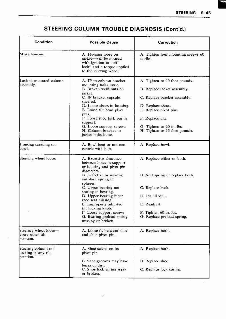
STEERING COLUMN TROUBLE DIAGNOSIS (Cont'd .)
STEERING
9- 45
Condition Possible Cause Correction
Miscellaneous . A. Housing loose on A. Tighten four mounting screws 60jacket-will be noticed in.-lbs.with ignition in "off-lock" and a torque appliedto the steering wheel.
Lash in mounted column A. IP to column bracket A. Tighten to 20 foot pounds .assembly . mounting bolts loose.
B. Broken weld nuts on B. Replace jacket assembly .jacket .C. IP bracket capsule C. Replace bracket assembly .sheared.D . Loose shoes in housing. D. Replace shoes.E. Loose tilt head pivot E. Replace pivot pins .pins.F. Loose shoe lock pin in F. Replace pin.support .G. Loose support screws . G. Tighten to 60 in.-lbs .H . Column bracket to H. Tighten to 15 foot pounds .jacket bolts loose.
Housing scraping on A. Bowl bent or not con- A. Replace bowl .owl. centric with hub.
Steering wheel loose. A. Excessive clearance A. Replace either or both .between holes in supportor housing and pivot pindiameters.B. Defective or missing B. Add spring or replace both.anti-lash spring inspheres.C. Upper bearing not C. Replace both .seating in bearing.D . Upper bearing inner D. Install seat .race seat missing.E. Improperly adjusted E. Readjust .tilt locking knob .F. Loose support screws . F. Tighten 60 in.-lbs .G . Bearing preload spring G. Replace preload spring .missing or broken.
Steering wheel loose- A. Loose fit between shoe A. Replace both .very other tilt and shoe pivot pin.
position .
Steering column not A. Shoe seized on its A. Replace both .locking in any tilt pivot pin.position .
B. Shoe grooves may have B. Replace shoe.burrs or dirt .C. Shoe lock spring weak C. Replace lock spring .or broken .
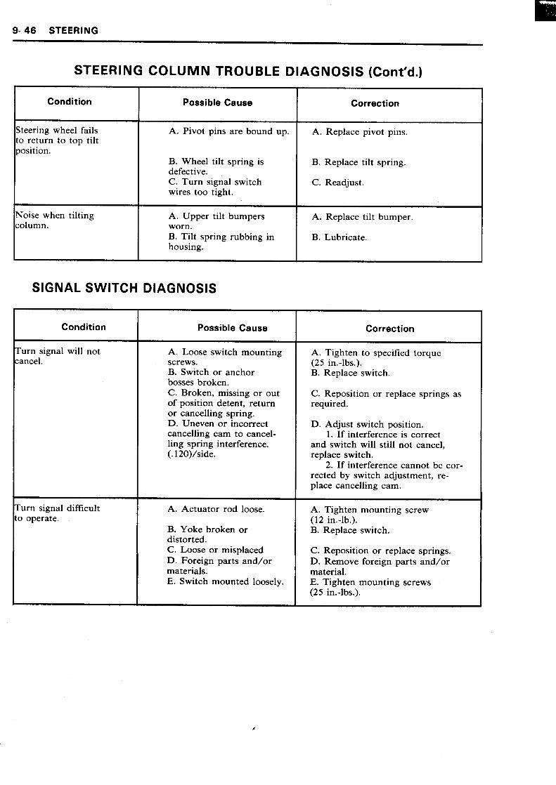
9- 46
STEERING
STEERING COLUMN TROUBLE DIAGNOSIS (Cont'd.)
SIGNAL SWITCH DIAGNOSIS
Condition Possible Cause Correction
Steering wheel fails A. Pivot pins are bound up.A
. Replace pivot pins .to return to top tiltposition .
B . Wheel tilt spring is B. Replace tilt spring .defective.C. Turn signal switch C. Readjust .wires too tight.
Noise when tilting A. Upper tilt bumpers A. Replace tilt bumper .column . worn .
B. Tilt spring rubbing in B. Lubricate.housing.
Condition Possible Cause Correction
Turn signal will not A. Loose switch mounting A. Tighten to specified torquecancel . screws . (25 in.-lbs.) .
B. Switch or anchor B. Replace switch .bosses broken .C. Broken, missing or out C. Reposition or replace springs asof position detent, return required.or cancelling spring .D. Uneven or incorrect D. Adjust switch position .cancelling cam to cancel- 1 . If interference is correctling spring interference . and switch will still not cancel,(.120)/side. replace switch .
2. If interference cannot be cor-rected by switch adjustment, re-place cancelling cam.
Turn signal difficult A. Actuator rod loose. A. Tighten mounting screwto operate. - (12 in.-lb .) .
B. Yoke broken or B. Replace switch .distorted.C. Loose or misplaced C. Reposition or replace springs.D. Foreign parts and/or D. Remove foreign parts and/ormaterials. material .E. Switch mounted loosely. E. Tighten mounting screws
(25 in.-lbs.) .
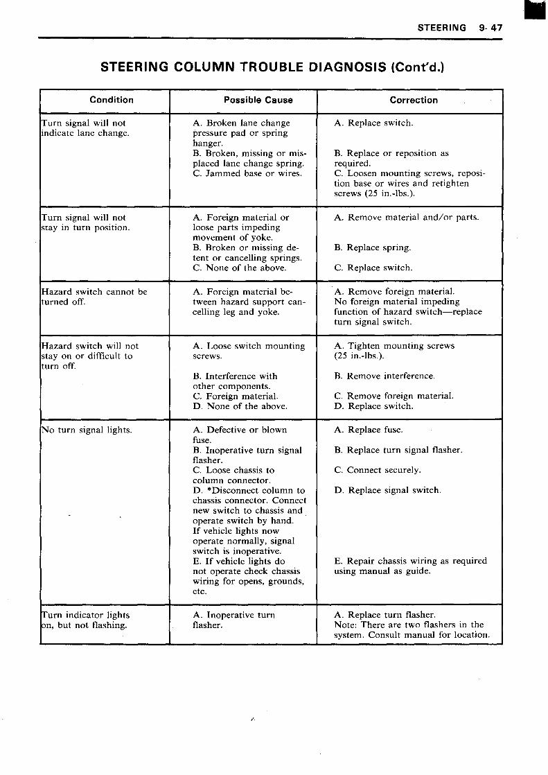
STEERING COLUMN TROUBLE DIAGNOSIS (Cont'd .)
STEERING
9- 47
Condition Possible Cause Correction
Turn signal will not A . Broken lane change A. Replace switch .indicate lane change . pressure pad or spring
hanger .B. Broken, missing or mis- B. Replace or reposition asplaced lane change spring . required.C. Jammed base or wires. C. Loosen mounting screws, reposi-
tion base or wires and retightenscrews (25 in.-lbs.) .
Turn signal will not A. Foreign material or A. Remove material and/or parts.stay in turn position . loose parts impeding
movement of yoke .B. Broken or missing de- B. Replace spring .tent or cancelling springs .C. None of the above. C. Replace switch .
Hazard switch cannot be A. Foreign material be- A. Remove foreign material .turned off. tween hazard support can- No foreign material impeding
celling leg and yoke . function of hazard switch-replaceturn signal switch .
Hazard switch will not A . Loose switch mounting A. Tighten mounting screwsstay on or difficult to screws . (25 in.-lbs.) .turn off.
B. Interference with B. Remove interference .other components .C. Foreign material . C. Remove foreign material.D. None of the above. D. Replace switch .
No turn signal lights . A. Defective or blown A. Replace fuse .fuse .B. Inoperative turn signal B. Replace turn signal flasher.flasher.C. Loose chassis to C. Connect securely .column connector.D. *Disconnect column to D. Replace signal switch .chassis connector. Connectnew switch to chassis and_
` operate switch by hand .If vehicle lights nowoperate normally, signalswitch is inoperative.E. If vehicle lights do E. Repair chassis wiring as requirednot operate check chassis using manual as guide.wiring for opens, grounds,etc.
Turn indicator lights A. Inoperative turn A. Replace turn flasher.n, but not flashing . flasher. Note : There are two flashers in the
system . Consult manual for location .
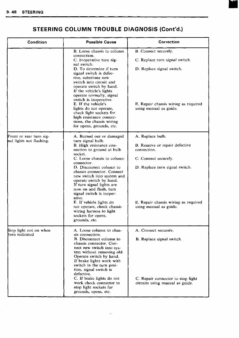
9- 48
STEERING
STEERING COLUMN TROUBLE DIAGNOSIS (Cont'd .)
Condition Possible Cause Correction
B. Loose chassis to column B . Connect securely.connection .C. Inoperative turn sig- C. Replace turn signal switch .nal switch .D. To determine if turn D. Replace signal switch .signal switch is defec-tive, substitute newswitch into circuit andoperate switch by hand .If the vehicle's lightsoperate normally, signalswitch is inoperative.E. If the vehicle's E. Repair chassis wiring as requiredlights do not operate, using manual as guide.check light sockets forhigh resistance connec-tions, the chassis wiringfor opens, grounds, etc.
Front or rear turn sig- A. Burned out or damaged A. Replace bulb .al lights not flashing . turn signal bulb .
B. High resistance con- B. Remove or repair defectivenection to ground at bulb connection .socket .C. Loose chassis to column C. Connect securely .connector.D. Disconnect column to D. Replace turn signal switch .chassis connector. Connectnew switch into system andoperate switch by hand .If turn signal lights arenow on and flash, turnsignal switch is inoper-ative.E. If vehicle lights do E. Repair chassis wiring as requirednot operate, check chassis using manual as guide.wiring harness to lightsockets for opens,grounds, etc.
Stop light not on when A. Loose column to chas- A. Connect securely .turn indicated sis connection .
B. Disconnect column to B. Replace signal switch.chassis connector. Con-nect new switch into sys-tem without removing old.Operate switch by hand.If brake lights work withswitch in the turn posi-tion, signal switch isdefective.C. If brake lights do not C. Repair connector to stop lightwork check connector to circuits using manual as guide.stop light sockets forgrounds, opens, etc.
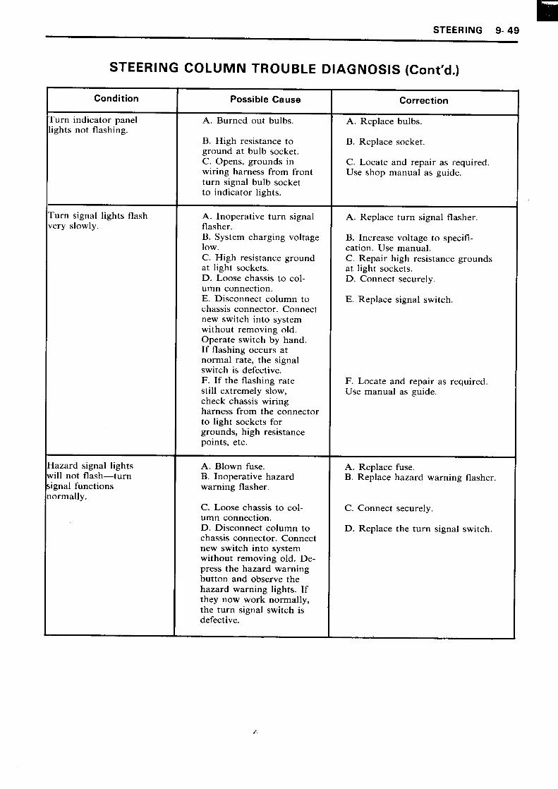
STEERING COLUMN TROUBLE DIAGNOSIS (Cont'd .)
STEERING
9- 49
Condition Possible Cause Correction
Turn indicator panel A. Burned out bulbs. A. Replace bulbs.lights not flashing .
B. High resistance to B. Replace socket .ground at bulb socket .C. Opens, grounds in C. Locate and repair as required .wiring harness from front Use shop manual as guide.turn signal bulb socketto indicator lights .
Turn signal lights flash A. Inoperative turn signal A. Replace turn signal flasher.very slowly . flasher.
B. System charging voltage B. Increase voltage to specifi-low . cation . Use manual .C. High resistance ground C. Repair high resistance groundsat light sockets. at light sockets.D. Loose chassis to col- D. Connect securely .umn connection .E. Disconnect column to E. Replace signal switch .chassis connector. Connectnew switch into systemwithout removing old.Operate switch by hand .If flashing occurs atnormal rate, the signalswitch is defective.F. If the flashing rate F. Locate and repair as required .still extremely slow, Use manual as guide.check chassis wiringharness from the connectorto light sockets forgrounds, high resistancepoints, etc.
Hazard signal lights A. Blown fuse . A. Replace fuse .will not flash-turn B. Inoperative hazard B . Replace hazard warning flasher.signal functions warning flasher.normally.
C. Loose chassis to col- C. Connect securely .umn connection ._D. Disconnect column to D. Replace the turn signal switch .chassis connector. Connectnew switch into systemwithout removing old. De-press the hazard warningbutton and observe thehazard warning lights . Ifthey now work normally,the turn signal switch isdefective.
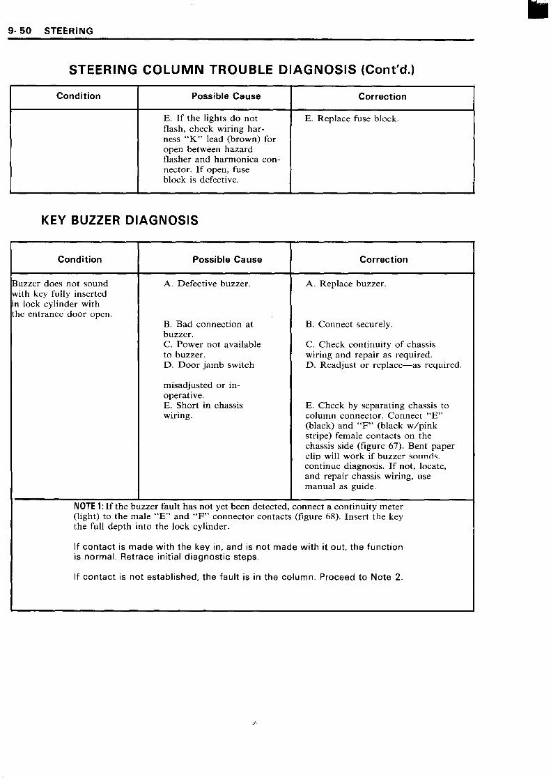
9- 50
STEERING
STEERING COLUMN TROUBLE DIAGNOSIS (Cont'd .)
KEY BUZZER DIAGNOSIS
Condition Possible Cause Correction
E. If the lights do not E. Replace fuse block.flash, check wiring har-ness "K" lead (brown) foropen between hazardflasher and harmonica con-nector . If open, fuseblock is defective.
Condition Possible Cause Correction
Buzzer does not sound A. Defective buzzer . A . Replace buzzer .with key fully insertedin lock cylinder withthe entrance door open .
B . Bad connection at B. Connect securely .buzzer .C. Power not available C. Check continuity of chassisto buzzer . wiring and repair as required .D . Door jamb switch D. Readjust or replace-as required .
misadjusted or in-operative.E. Short in chassis E. Check by separating chassis towiring . column connector. Connect "E"
(black) and "F" (black w/pinkstripe) female contacts on thechassis side (figure 67). Bent paperclip will work if buzzer sound- .continue diagnosis. If not, locate,and repair chassis wiring, usemanual as guide.
NOTE 1 : If the buzzer fault has not yet been detected, connect a continuity meter_ (light) to the male "E" and "F" connector contacts (figure 68). Insert the keythe full depth into the lock cylinder .
If contact is made with the key in, and is not made with it out, the functionis normal . Retrace initial diagnostic steps .
If contact is not established, the fault is in the column . Proceed to Note 2.
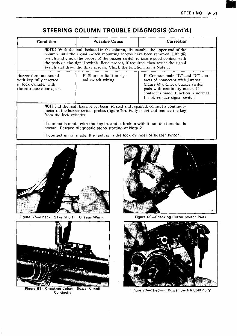
STEERING COLUMN TROUBLE DIAGNOSIS (Cont'd .)
Figure 68-Checking Column Buzzer CircuitContinuity
STEERING
9- 51
Figure 67-Checking For Short In Chassis Wiring
Figure 69-Checking Buzzer Switch Pads
Figure 70-Checking Buzzer Switch Continuity
Condition Possible Cause Correction
NOTE 2: With the fault isolated in the column, disassemble the upper end of thecolumn until the signal switch mounting screws have been removed . Lift theswitch and check the probes of the buzzer switch to insure good contact withthe pads on the signal switch . Bend probes, if required, then reseat the signalswitch and drive the three screws . Check the function, as in Note I.
:')uzzer does not sound F. Short or fault in sig- F. Connect male "E" and "F" con-with key fully inserted nal switch wiring . tacts of connector with jumper'n lock cylinder with (figure 69). Check buzzer switchhe entrance door open . pads with continuity meter. If
contact is made, function is normal .If not, replace signal switch .
NOTE 3: If the fault has not yet been isolated and repaired, connect a continuitymeter to the buzzer switch probes (figure 70) . Fully insert and remove the keyfrom the lock cylinder .
If contact is made with the key in, and is broken with it out, the function isnormal . Retrace diagnostic steps starting at Note 2 .
If contact is not made, the fault is in the lock cylinder or buzzer switch .
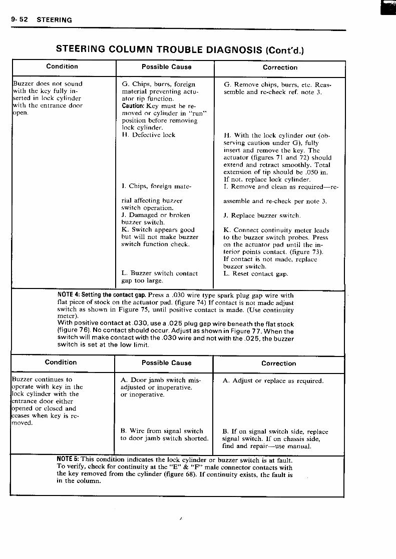
9- 52
STEERING
STEERING COLUMN TROUBLE DIAGNOSIS (Cont'd .)Condition Possible Cause Correction
Buzzer does not sound G. Chips, burrs, foreign G. Remove chips, burrs, etc. Reas-with the key fully in- material preventing actu- semble and re-check ref. note 3.serted in lock cylinder ator tip function .with the entrance door Caution : Key must be re-open . moved or cylinder in "run"
position before removinglock cylinder .H. Defective lock H. With the lock cylinder out (ob-
serving caution under G), fullyinsert and remove the key. Theactuator (figures 71 and 72) shouldextend and retract smoothly . Totalextension of tip should be .050 in .If not, replace lock cylinder.
I. Chips, foreign mate- I. Remove and clean as required-re-
rial affecting buzzer assemble and re-check per note 3.switch operation.J. Damaged or broken J . Replace buzzer switch .buzzer switch .K. Switch appears good K. Connect continuity meter leadsbut will not make buzzer to the buzzer switch probes . Pressswitch function check. on the actuator pad until the in-
terior points contact. (figure 73).If contact is not made, replacebuzzer switch .
L. Buzzer switch contact L. Reset contact gap.gap too large.
NOTE 4 : Setting the contact gap. Press a .030 wire type spark plug gap wire withflat piece of stock on the actuator pad. (figure 74) If contact is not made adjustswitch as shown in Figure 75, until positive contact is made. (Use continuitymeter) .With positive contact at .030, use a .025 plug gap wire beneath the flat stock(figure 76) . No contact should occur . Adjust as shown in Figure 77 . When theswitch will make contact with the .030 wire and not with the .025, the buzzerswitch is set at the low limit .
Condition Possible Cause Correction
Buzzer continues to A. Door jamb switch mis- A. Adjust or replace as required .operate with key in the adjusted or inoperative.lock cylinder with the or inoperative.entrance door eitheropened or closed andceases when key is re-moved.
B. Wire from signal switch B. If on signal switch side, replaceto door jamb switch shorted. signal switch . If on chassis side,
find and repair-use manual .
NOTE 5: This condition indicates the lock cylinder or buzzer switch is at fault.To verify, check for continuity at the "E" & "F" male connector contacts withthe key removed from the cylinder (figure 68). If continuity exists, the fault isin the column.
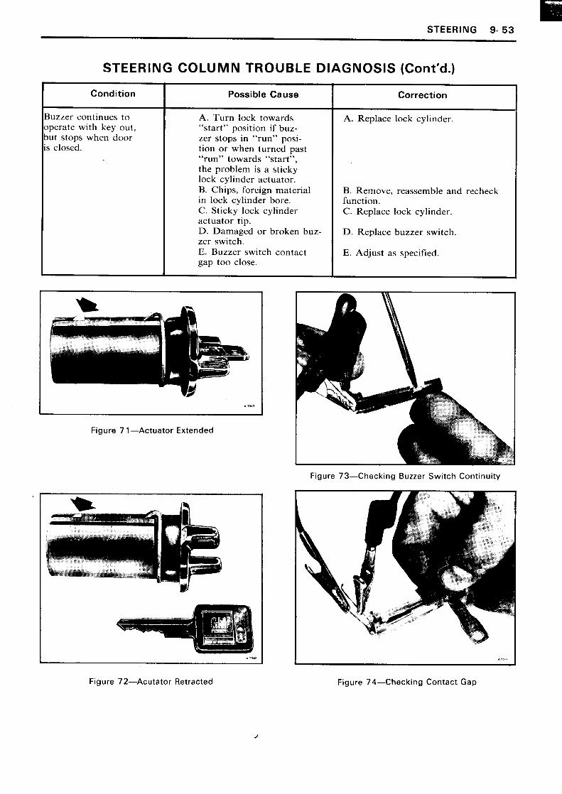
STEERING COLUMN TROUBLE DIAGNOSIS (Cont'd .)
Figure 71-Actuator Extended
Figure 72-Actuator Retracted
Figure 74-Checking Contact Gap
STEERING
9- 53
Figure 73-Checking Buzzer Switch Continuity
Condition Possible Cause Correction
Buzzer continues to A. Turn lock towards A. Replace lock cylinder .operate with key out, "start' position if buz-ut stops when door zer stops in "run" posi-
is closed . tion or when turned past"run" towards "start",the problem is a stickylock cylinder actuator .B. Chips, foreign material B. Remove, reassemble and recheckin lock cylinder bore . function.C. Sticky lock cylinder C. Replace lock cylinder.actuator tip.D . Damaged or broken buz- D. Replace buzzer switch .zer switch .E. Buzzer switch contact E. Adjust as specified.gap too close.
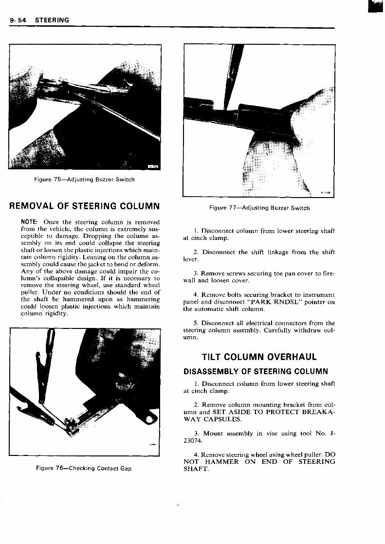
9- 54
STEERING
Figure 75-Adjusting Buzzer Switch
REMOVAL OF STEERING COLUMN
NOTE : Once the steering column is removedfrom the vehicle, the column is extremely sus-ceptible to damage. Dropping the column as-sembly on its end could collapse the steeringshaft or loosen the plastic injections which main-tain column rigidity . Leaning on the column as-sembly could cause the jacket to bend or deform .Any of the above damage could impair the co-lumn's collapsible design . If it is necessary toremove the steering wheel, use standard wheelpuller . Under no conditions should the end ofthe shaft be hammered upon as hammeringcould loosen plastic injections which maintaincolumn rigidity .
Figure 76-Checking Contact Gap
Figure 77-Adjusting Buzzer Switch
1 . Disconnect column from lower steering shaftat cinch clamp.
2 . Disconnect the shift linkage from the shiftlever .
3 . Remove screws securing toe pan cover to fire-wall and loosen cover.
4. Remove bolts securing bracket to instrumentpanel and disconnect "PARK RNDSL" pointer onthe automatic shift column .
5 . Disconnect all electrical connectors from thesteering column assembly . Carefully withdraw col-umn .
TILT COLUMN OVERHAUL
DISASSEMBLY OF STEERING COLUMN1 . Disconnect column from lower steering shaft
at cinch clamp.
2. Remove column mounting bracket from col-umn and SET ASIDE TO PROTECT BREAKA-WAY CAPSULES.
3 . Mount assembly in vise using tool No. J-23074.
4. Remove steering wheel using wheel puller . DONOT HAMMER ON END OF STEERINGSHAFT.
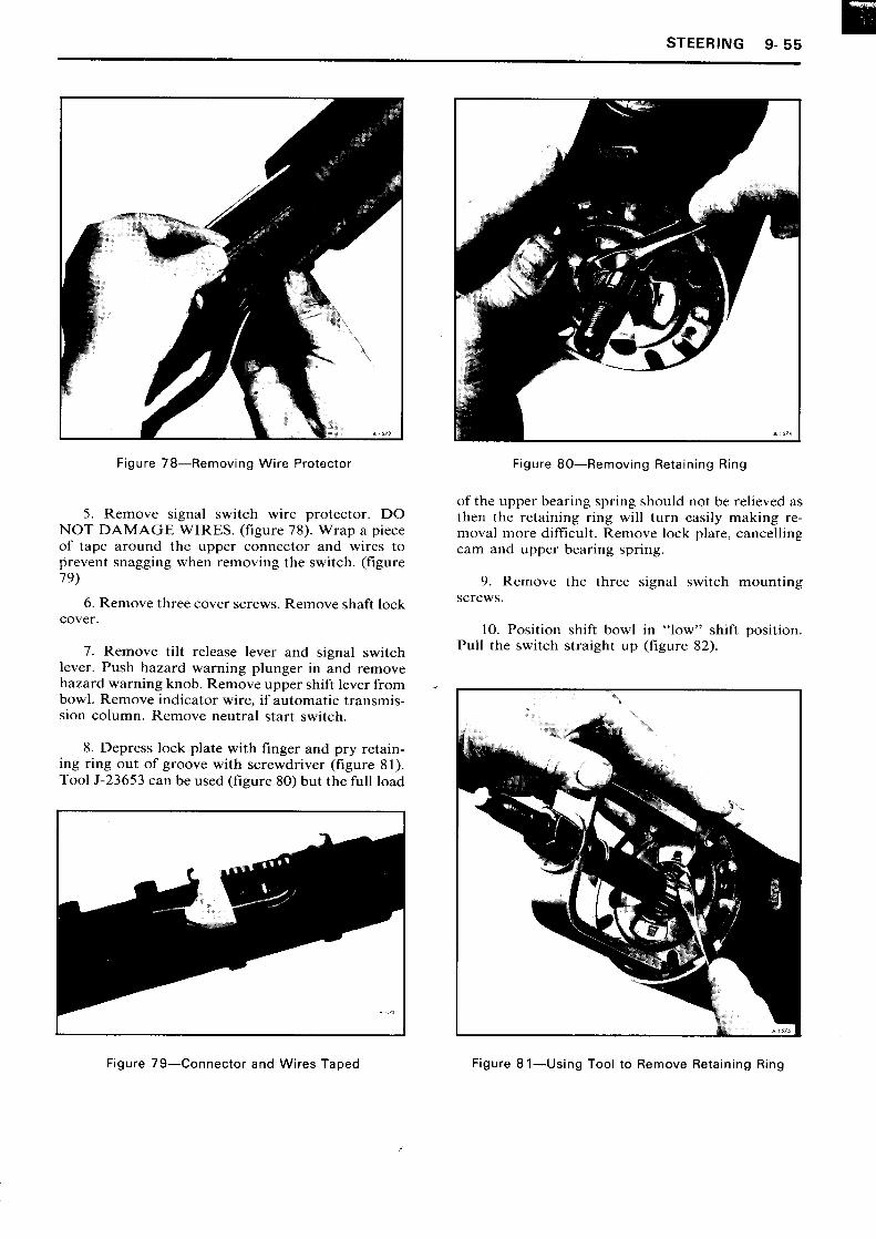
Figure 78-Removing Wire Protector
5 . Remove signal switch wire protector. DONOT DAMAGE WIRES. (figure 78). Wrap a pieceof tape around the upper connector and wires toprevent snagging when removing the switch . (figure79)
6. Remove three cover screws . Remove shaft lockcover.
7. Remove tilt release lever and signal switchlever. Push hazard warning plunger in and removehazard warning knob. Remove upper shift lever frombowl . Remove indicator wire, if automatic transmis-sion column . Remove neutral start switch .
8 . Depress lock plate with finger and pry retain-ing ring out of groove with screwdriver (figure 81).Tool J-23653 can be used (figure 80) but the full load
Figure 79-Connector and Wires Taped
STEERING
9- 55
Figure 80-Removing Retaining Ring
of the upper bearing spring should not be relieved asthen the retaining ring will turn easily making re-moval more difficult. Remove lock plate, cancellingcam and upper bearing spring .
9. Remove the three signal switch mountingscrews .
10 . Position shift bowl in "low" shift position .Pull the switch straight up (figure 82).
Figure 81-Using Tool to Remove Retaining Ring
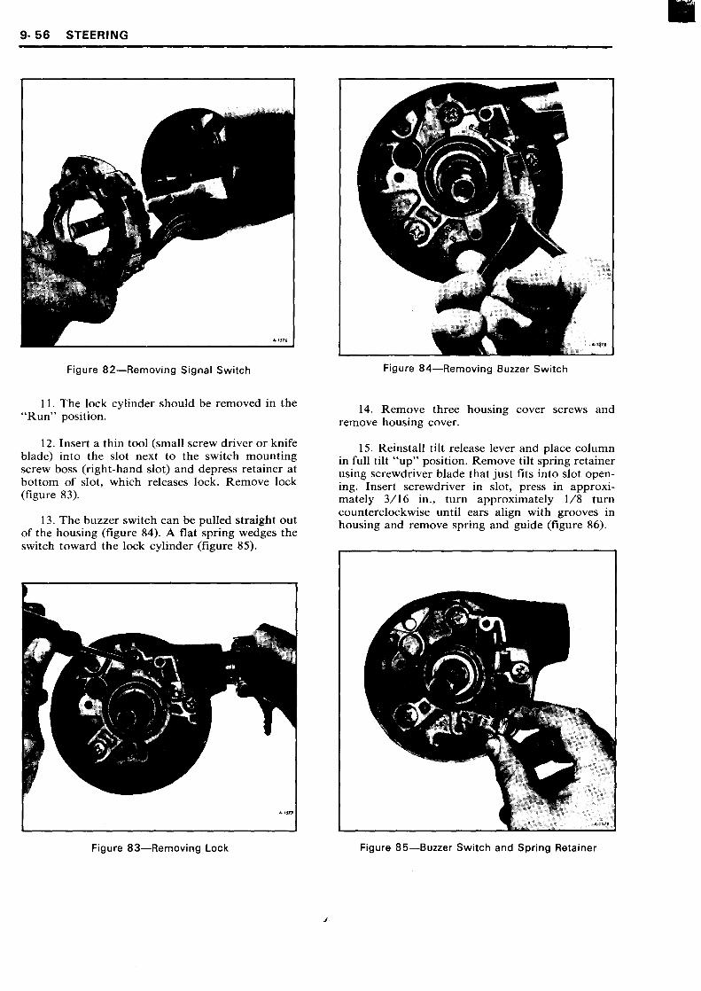
9- 56
STEERING
Figure 82-Removing Signal Switch
11 . The lock cylinder should be removed in the"Run" position .
12 . Insert a thin tool (small screw driver or knifeblade) into the slot next to the switch mountingscrew boss (right-hand slot) and depress retainer atbottom of slot, which releases lock . Remove lock(figure 83).
13 . The buzzer switch can be pulled straight outof the housing (figure 84). A flat spring wedges theswitch toward the lock cylinder (figure 85).
Figure 83-Removing Lock
Figure 84-Removing Buzzer Switch
14 . Remove three housing cover screws andremove housing cover.
15 . Reinstall tilt release lever and place columnin full tilt "up" position . Remove tilt spring retainerusing screwdriver blade that just fits into slot opening. Insert screwdriver in slot, press in approxi-mately 3/16 in ., turn approximately 1/8 turncounterclockwise until ears align with grooves inhousing and remove spring and guide (figure 86) .
Figure 85-Buzzer Switch and Spring Retainer
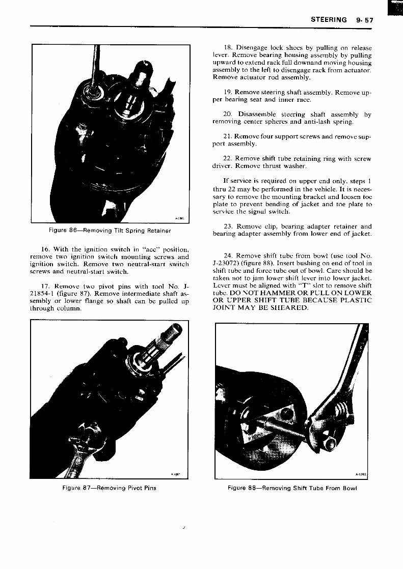
Figure 86-Removing Tilt Spring Retainer
16 . With the ignition switch in "acc" position,remove two ignition switch mounting screws andignition switch . Remove two neutral-start switchscrews and neutral-start switch.
17 . Remove two pivot pins with tool No. J-21854-1 (figure 87). Remove intermediate shaft as-sembly or lower flange so shaft can be pulled upthrough column.
Figure 87-Removing Pivot Pins
STEERING
9- 57
18 . Disengage lock shoes by pulling on releaselever. Remove bearing housing assembly by pullingupward to extend rack full downand moving housingassembly to the left to disengage rack from actuator .Remove actuator rod assembly .
19 . Remove steering shaft assembly . Remove up-per bearing seat and inner race .
20 . Disassemble steering shaft assembly byremoving center spheres and anti-lash spring .
21 . Remove four support screws and remove sup-port assembly .
22 . Remove shift tube retaining ring with screwdriver . Remove thrust washer .
If service is required on upper end only, steps 1thru 22 may be performed in the vehicle. It is neces-sary to remove the mounting bracket and loosen toeplate to prevent bending of jacket and toe plate toservice the signal switch .
23 . Remove clip, bearing adapter retainer andbearing adapter assembly from lower end of jacket .
24 . Remove shift tube from bowl (use tool No.J-23072) (figure 88). Insert bushing on end of tool inshift tube and force tube out of bowl . Care should betaken not to jam lower shift lever into lower jacket.Lever must be aligned with "T" slot to remove shifttube . DO NOTHAMMER OR PULL ON LOWEROR UPPER SHIFT TUBE BECAUSE PLASTICJOINT MAY BE SHEARED.
Figure 88-Removing Shift Tube From Bowl
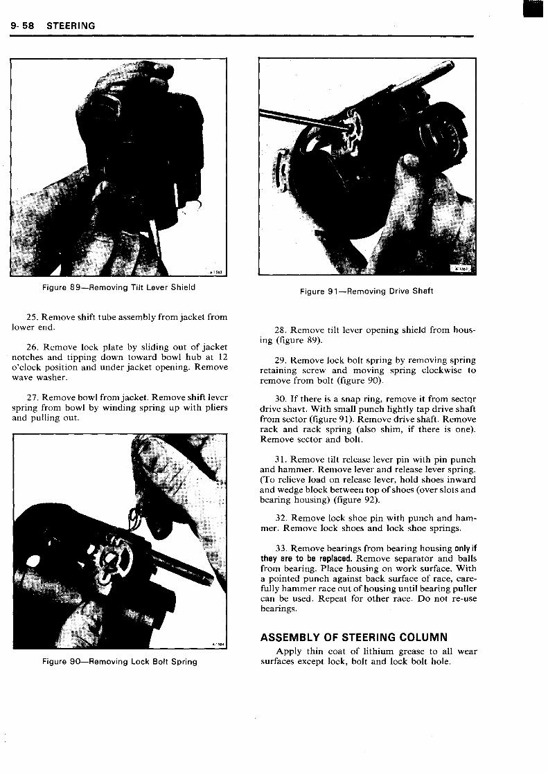
9- 58
STEERING
Figure 89-Removing Tilt Lever Shield
25 . Remove shift tube assembly from jacket fromlower end.
26 . Remove lock plate by sliding out of jacketnotches and tipping down toward bowl hub at 12o'clock position and under jacket opening. Removewave washer .
27 . Remove bowl from jacket. Remove shift leverspring from bowl by winding spring up with pliersand pulling out.
Figure 90-Removing Lock Bolt Spring
Figure 91-Removing Drive Shaft
28 . Remove tilt lever opening shield from hous-ing (figure 89).
29 . Remove lock bolt spring by removing springretaining screw and moving spring clockwise toremove from bolt (figure 90).
30 . If there is a snap ring, remove it from sectordrive shavt . With small punch lightly tap drive shaftfrom sector (figure 91). Remove drive shaft. Removerack and rack spring (also shim, if there is one) .Remove sector and bolt .
31 . Remove tilt release lever pin with pin punchand hammer. Remove lever and release lever spring.(To relieve load on release lever, hold shoes inwardand wedge block between top ofshoes (over slots andbearing housing) (figure 92).
32 . Remove lock shoe pin with punch and ham-mer. Remove lock shoes and lock shoe springs.
33 . Remove bearings from bearing housing only ifthey are to be replaced . Remove separator and ballsfrom bearing. Place housing on work surface. Witha pointed punch against back surface of race, care-fully hammer race out of housing until bearing pullercan be used . Repeat for other race . Do not re-usebearings .
ASSEMBLY OF STEERING COLUMNApply thin coat of lithium grease to all wear
surfaces except lock, bolt and lock bolt hole.
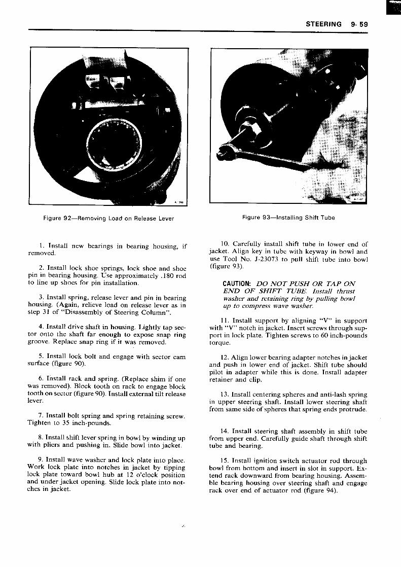
Figure 92-Removing Load on Release Lever
1 . Install new bearings in bearing housing, ifremoved.
2. Install lock shoe springs, lock shoe and shoepin in bearing housing. Use approximately .180 rodto line up shoes for pin installation .
3. Install spring, release lever and pin in bearinghousing. (Again, relieve load on release lever as instep 31 of "Disassembly of Steering Column".
4. Install drive shaft in housing. Lightly tap sec-tor onto the shaft far enough to expose snap ringgroove . Replace snap ring if it was removed.
5 . Install lock bolt and engage with sector camsurface (figure 90).
6. Install rack and spring . (Replace shim if onewas removed) . Block tooth on rack to engage blocktooth on sector (figure 90). Install external tilt releaselever.
7. Install bolt spring and spring retaining screw.Tighten to 35 inch-pounds.
8. Install shift lever spring in bowl by winding upwith pliers and pushing in . Slide bowl into jacket .
9. Install wave washer and lock plate into place.Work lock plate into notches in jacket by tippinglock plate toward bowl hub at 12 o'clock positionand under jacket opening. Slide lock plate into not-ches in jacket .
Figure 93-Installing Shift Tube
STEERING
9- 59
10 . Carefully install shift tube in lower end ofjacket . Align key in tube with keyway in bowl anduse Tool No. J-23073 to pull shift tube into bowl(figure 93).
CAUTION: DO NOTPUSH OR TAP ONEND OF SHIFT TUBE. Install thrustwasher and retaining ring by pulling bowlup to compress wave washer.
11 . Install support by aligning "V" in supportwith "V" notch in jacket . Insert screws through sup-port in lock plate. Tighten screws to 60 inch-poundstorque .
12 . Align lower bearing adapter notches in jacketand push in lower end of jacket . Shift tube shouldpilot in adapter while this is done . Install adapterretainer and clip .
13 . Install centering spheres and anti-lash springin upper steering shaft. Install lower steering shaftfrom same side of spheres that spring ends protrude .
14 . Install steering shaft assembly in shift tubefrom upper end. Carefully guide shaft through shifttube and bearing.
15 . Install ignition switch actuator rod throughbowl from bottom and insert in slot in support. Ex-tend rack downward from bearing housing. Assemble bearing housing over steering shaft and engagerack over end of actuator rod (figure 94).
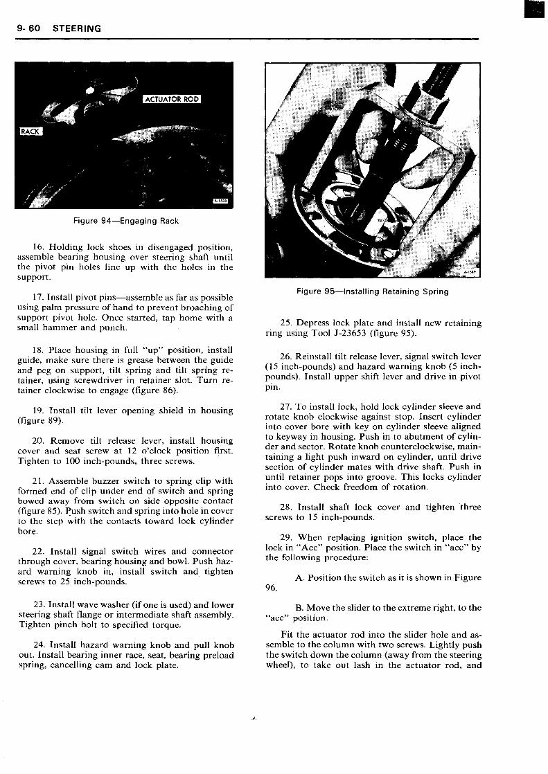
9- 60
STEERING
Figure 94-Engaging Rack
16 . Holding lock shoes in disengaged position,assemble bearing housing over steering shaft untilthe pivot pin holes line up with the holes in thesupport.
17 . Install pivot pins-assemble as far as possibleusing palm pressure of hand to prevent broaching ofsupport pivot hole . Once started, tap home with asmall hammer and punch.
18 . Place housing in full "up" position, installguide, make sure there is grease between the guideand peg on support, tilt spring and tilt spring retainer, using screwdriver in retainer slot . Turn re-tainer clockwise to engage (figure 86).
19 . Install tilt lever opening shield in housing(figure 89).
20 . Remove tilt release lever, install housingcover and seat screw at 12 o'clock position first .Tighten to 100 inch-pounds, three screws .
21 . Assemble buzzer switch to spring clip withformed end of clip under end of switch and springbowed away from switch on side opposite contact(figure 85). Push switch and spring into hole in coverto the step with the contacts toward lock cylinderbore .
22 . Install signal switch wires and connectorthrough cover, bearing housing and bowl . Push haz-ard warning knob in, install switch and tightenscrews to 25 inch-pounds.
23 . Install wave washer (if one is used) and lowersteering shaft flange or intermediate shaft assembly .Tighten pinch bolt to specified torque .
24 . Install hazard warning knob and pull knobout. Install bearing inner race, seat, bearing preloadspring, cancelling cam and lock plate.
Figure 95-Installing Retaining Spring
25 . Depress lock plate and install new retainingring using Tool J-23653 (figure 95).
26 . Reinstall tilt release lever, signal switch lever(15 inch-pounds) and hazard warning knob (5 inch-pounds). Install upper shift lever and drive in pivotpin.
27 . To install lock, hold lock cylinder sleeve androtate knob clockwise against stop . Insert cylinderinto cover bore with key on cylinder sleeve alignedto keyway in housing. Push in to abutment of cylin-der and sector . Rotate knob counterclockwise, main-taining a light push inward on cylinder, until drivesection of cylinder mates with drive shaft. Push inuntil retainer pops into groove . This locks cylinderinto cover. Check freedom of rotation .
28 . Install shaft lock cover and tighten threescrews to 15 inch-pounds.
29 . When replacing ignition switch, place thelock in "Acc" position . Place the switch in "acc" bythe following procedure :
96 .A. Position the switch as it is shown in Figure
B . Move the slider to the extreme right, to the"acc" position .
Fit the actuator rod into the slider hole and as-semble to the column with two screws . Lightly pushthe switch down the column (away from the steeringwheel), to take out lash in the actuator rod, and
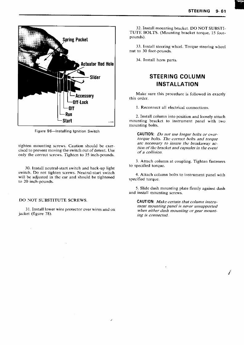
Figure 96-Installing Ignition Switch
tighten mounting screws . Caution should be exer-cised to prevent moving the switch out ofdetent . Useonly the correct screws . Tighten to 35 inch-pounds.
30 . Install neutral-start switch and back-up lightswitch . Do not tighten screws . Neutral-start switchwill be adjusted in the car and should be tightenedto 20 inch-pounds.
DO NOT SUBSTITUTE SCREWS.
31 . Install lower wire protector over wires and onjacket (figure 78).
34. Install horn parts.
STEERING COLUMNINSTALLATION
STEERING
9- 61
32 . Install mounting bracket. DO NOT SUBSTI-TUTE BOLTS. (Mounting bracket torque, 15 foot-pounds).
33 . Install steering wheel. Torque steering wheelnut to 30 foot-pounds.
Make sure this procedure is followed in exactlythis order.
1 . Reconnect all electrical connections.
2. Install column into position and loosely attachmounting bracket to instrument panel with twomounting bolts.
CAUTION : Do not use longer bolts or over-torque bolts. The correct bolts and torqueare necessary to insure the breakaway ac-tion ofthe bracket and capsules in the eventofa collision .
3. Attach column at coupling . Tighten fastenersto specified torque .
4. Attach column bolts to instrument panel withspecified torque.
5. Slide dash mounting plate firmly against dashand install mounting screws .
CAUTION : Make certain that column instru-ment mounting panel is never unsupportedwhen either dash mounting or gear mount-ing is connected.
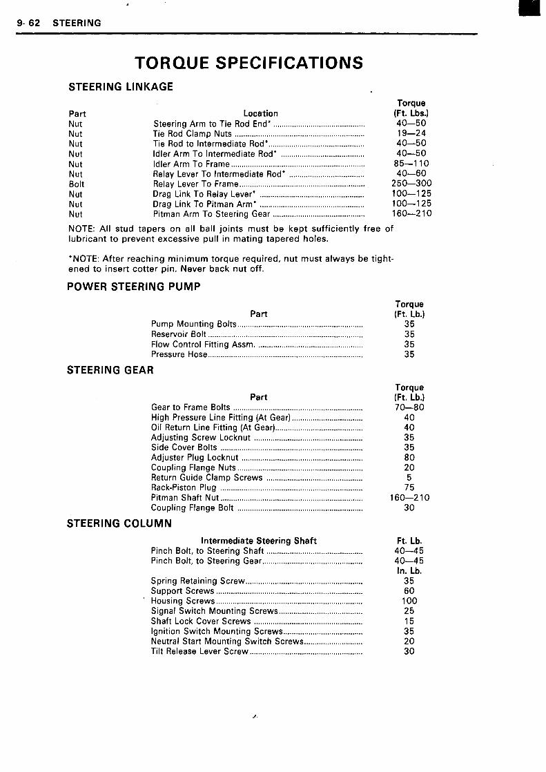
9- 62
STEERING
STEERING LINKAGE
NOTE : All stud tapers on all ball joints must be kept sufficiently free oflubricant to prevent excessive pull in mating tapered holes.
'NOTE: After reaching minimum torque required, nut must always be tight-ened to insert cotter pin . Never back nut off.
POWER STEERING PUMP
TORQUE SPECIFICATIONS
TorquePart
(Ft. Lb.)Pump Mounting Bolts . . . . . . . . . . . . . . . . . . . . . . . . . . . . . . . . . . . . . . . . . . . . . . . . . . . . . . . . . . . .
35Reservoir Bolt . . . . . . . . . . . . . . . . . . . . . . . . . . . . . . . . . . . . . . . . . . . . . . . . . . . . . . . . . . . . . . . . . . . . . . . . . .Flow Control Fitting Assm . . . . . . . . . . . . . . . . . . . . . . . . . . . . . . . . . . . . . . . . . . . . . . . . . . .Pressure Hose . . . . . . . . . . . . . . . . . . . . . . . . . . . . . . . . . . . . . . . . . . . . . . . . . . . . . . . . . . . . . . . . . . . . . . . . . .
STEERING GEAR
353535
TorquePart (Ft. Lb .)
Gear to Frame Bolts . . . . . . . . . . . . . . . . . . . . . . . . . . . . . . . . . . . . . . . . . . . . . . . . . . . . . . . . . . . . . . 70-80High Pressure Line Fitting (At Gear) . . . . . . . . . . . . . . . . . . . . . . . . . . . . . . . . . . 40Oil Return Line Fitting (At Gear). . . . . . . . . . . . . . . . . . . . . . . . . . . . . . . . . . . . . . . . . . 40Adjusting Screw Locknut . . . . . . . . . . . . . . . . . . . . . . . . . . . . . . . . . . . . . . . . . . . . . . . . . . . . 35Side Cover Bolts . . . . . . . . . . . . . . . . . . . . . . . . . . . . . . . . . . . . . . . . . . . . . . . . . . . . . . . . . . . . . . . . . . . . 35Adjuster Plug Locknut . . . . . . . . . . . . . . . . . . . . . . . . . . . . . . . . . . . . . . . . . . . . . . . . . . . . . . . . . . 80Coupling Flange Nuts . . . . . . . . . . . . . . . . . . . . . . . . . . . . . . . . . . . . . . . . . . . . . . . . . . . . . . . . . . . . 20Return Guide Clamp Screws . . . . . . . . . . . . . . . . . . . . . . . . . . . . . . . . . . . . . . . . . . . . . . 5Rack-Piston Plug . . . . . . . . . . . . . . . . . . . . . . . . . . . . . . . . . . . . . . . . . . . . . . . . . . . . . . . . . . . . . . . . . . . . 75Pitman Shaft Nut . . . . . . . . . . . . . . . . . . . . . . . . . . . . . . . . . . . . . . . . . . . . . . . . . . . . . . . . . . . . . . . . . . . . 160-210Coupling Flange Bolt . . . . . . . . . . . . . . . . . . . . . . . . . . . . . . . . . . . . . . . . . . . . . . . . . . . . . . . . . . . . 30
TorquePart Location (Ft. Lbs.)Nut Steering Arm to Tie Rod End' . . . . . . . . . . . . . . . . . . . . . . . . . . . . . . . . . . . . . . . . . . . . 40-50Nut Tie Rod Clamp Nuts . . . . . . . . . . . . . . . . . . . . . . . . . . . . . . . . . . . . . . . . . . . . . . . . . . . . . . . . . . . . . . 19-24Nut Tie Rod to Intermediate Rod" . . . . . . . . . . . . . . . . . . . . . . . . . . . . . . . . . . . . . . . . . . . . . . 40-50Nut Idler Arm To Intermediate Rod' . . . . . . . . . . . . . . . . . . . . . . . . . . . . . . . . . . . . . . . . 40-50Nut Idler Arm To Frame . . . . . . . . . . . . . . . . . . . . . . . . . . . . . . . . . . . . . . . . . . . . . . . . . . . . . . . . . . . . . . . . 85-110Nut Relay Lever To Intermediate Rod" . . . . . . . . . . . . . . . . . . . . . . . . . . . . . . . . . . . . 40-60Bolt Relay Lever To Frame . . . . . . . . . . . . . . . . . . . . . . . . . . . . . . . . . . . . . . . . . . . . . . . . . . . . . . . . . . . . . 250-300Nut Drag Link To Relay Lever" . . . . . . . . . . . . . . . . . . . . . . . . . . . . . . . . . . . . . . . . . . . . . . . . . . 100-125Nut Drag Link To Pitman Arm' . . . . .. . . . . . . . . . . . . . . . . . . . . . . . . . . . . . . . . . . . . . . . . . . . . 100-125Nut Pitman Arm To Steering Gear . . . . . . . . . . . . . . . . . . . . . . . . . . . . . . . . . . . . . . . . . . . . 160-210
STEERING COLUMNIntermediate Steering Shaft Ft. Lb.
Pinch Bolt, to Steering Shaft . . . . . . . . . . . . . . . . . . . . . . . . . . . . . . . . . . . . . . . . . . . . . . 40-45Pinch Bolt, to Steering Gear . . . . . . . . . . . . . . . . . . . . . . . . . . . . . . . . . . . . . . . . . . . . . . . . 40-45
In . Lb .Spring Retaining Screw . . . . . . . . . . . . . . . . . . . . . . . . . . . . . . . . . . . . . . . . . . . . . . . . . . . . . . . . 35Support Screws . . . . . . . . . . . . . . . . . . . . . . . . . . . . . . . . . . . . . . . . . . . . . . . . . . . . . . . . . . . . . . . . . . . . . . 60Housing Screws . . . . . . . . . . . . . . . . . . . . . . . . . . . . . . . . . . . . . . . . . . . . . . . . . . . . . . . . . . . . . . . . . . . . . . 100Signal Switch Mounting Screws . . . . . . . . . . . . . . . . . . . . . . . . . . . . . . . . . . . . . . . . 25Shaft Lock Cover Screws . . . . . . . . . . . . . . . . . . . . . . . . . . . . . . . . . . . . . . . . . . . . . . . . . . . . 15Ignition Switch Mounting Screws . . . . . . . . . . . . . . . . . . . . . . . . . . . . . . . . . . . . . . 35Neutral Start Mounting Switch Screws . . . . . . . . . . . . . . . . . . . . . . . . . . . . 20Tilt Release Lever Screw . . . . . . . . . . . . . . . . . . . . . . . . . . . . . . . . . . . . . . . . . . . . . . . . . . . . . . 30
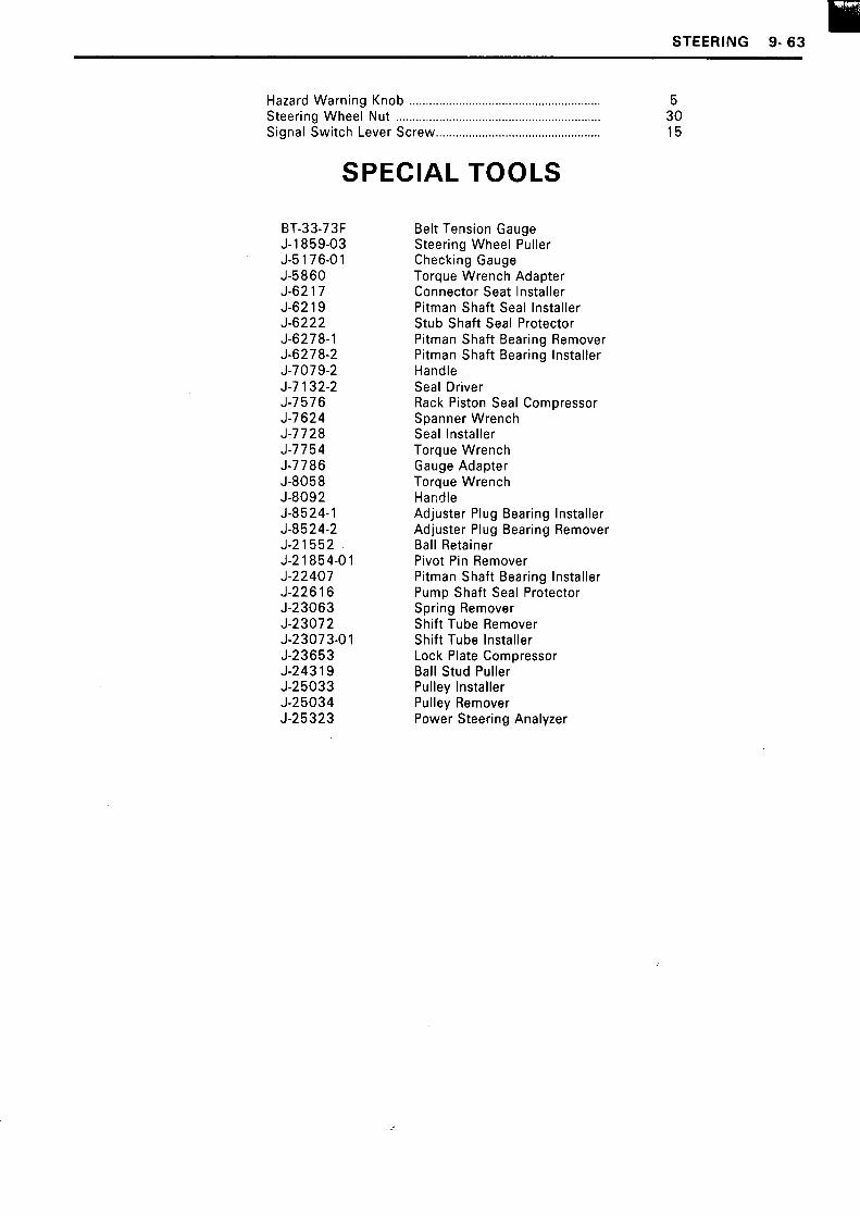
Hazard Warning Knob . . . . . . . . . . . . . . . . . . . . . . . . . . . . . . . . . . . . . . . . . . . . . . . . . . . . . . . . . .
5Steering Wheel Nut . . . . . . . . . . . . . . . . . . . . . . . . . . . . . . . . . . . . . . . . . . . . . . . . . . . . . . . . . . . . . .
30Signal Switch Lever Screw. . . . . . . . . . . . . . . . . . . . . . . . . . . . . . . . . . . . . . . . . . . . . . . . . .
15
SPECIAL TOOLS
BT-33-73F
Belt Tension GaugeJ-1859-03
Steering Wheel PullerJ-5176-01
Checking GaugeJ-5860
Torque Wrench AdapterJ-6217
Connector Seat InstallerJ-6219
Pitman Shaft Seal InstallerJ-6222
Stub Shaft Seal ProtectorJ-6278-1
Pitman Shaft Bearing RemoverJ-6278-2
Pitman Shaft Bearing InstallerJ-7079-2 HandleJ-7132-2
Seal DriverJ-7576
Rack Piston Seal CompressorJ-7624
Spanner WrenchJ-7728
Seal InstallerJ-7754
Torque WrenchJ-7786
Gauge AdapterJ-8058
Torque WrenchJ-8092 HandleJ-8524-1
Adjuster Plug Bearing InstallerJ-8524-2
Adjuster Plug Bearing RemoverJ-21552
Ball RetainerJ-21854-01
Pivot Pin RemoverJ-22407
Pitman Shaft Bearing InstallerJ-22616
Pump Shaft Seal ProtectorJ-23063
Spring RemoverJ-23072
Shift Tube RemoverJ-23073-01
Shift Tube InstallerJ-23653
Lock Plate CompressorJ-24319
Ball Stud PullerJ-25033
Pulley InstallerJ-25034
Pulley RemoverJ-25323
Power Steering Analyzer
STEERING
9- 63