Embed Size (px)
Citation preview
Storage Battery Systems, LLC • N56 W16665 Ridgewood Dr. • Menomonee Falls, WI 53051
www.sbsbattery.com • [email protected] • Toll Free: 800-554-2243
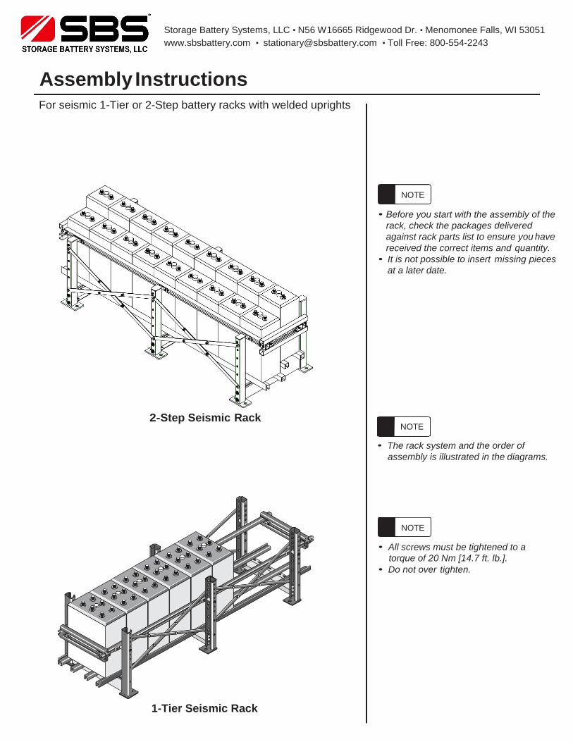
Assembly Instructions For seismic 1-Tier or 2-Step battery racks with welded uprights
• Before you start with the assembly of the
rack, check the packages delivered
against rack parts list to ensure you have
received the correct items and quantity.
• It is not possible to insert missing pieces
at a later date.
2- Step Seismic Rack
• The rack system and the order of
assembly is illustrated in the diagrams.
• All screws must be tightened to a
torque of 20 Nm [14.7 ft. lb.].
• Do not over tighten.
1-Tier Seismic Rack
NOTE
NOTE
NOTE
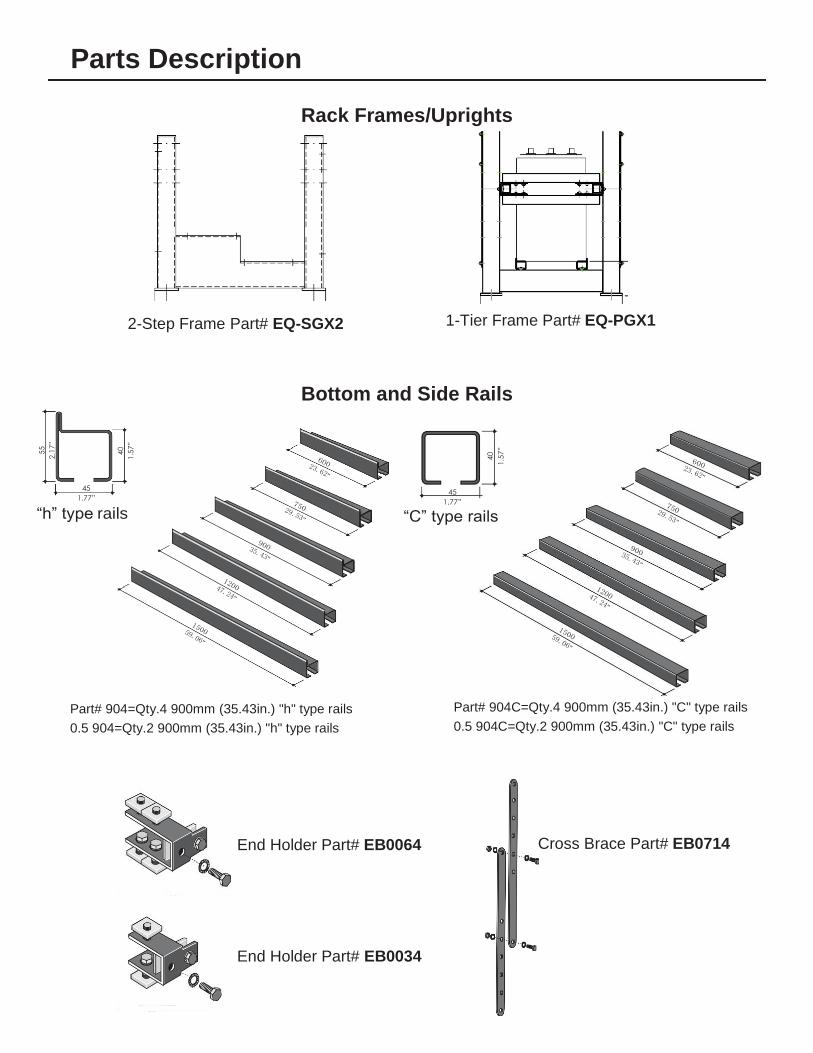
Parts Description
Rack Frames/Uprights
2-Step Frame Part# EQ-SGX2 1-Tier Frame Part# EQ-PGX1
Bottom and Side Rails
45
1.77”
“h” type rails
45
1.77”
“C” type rails
Part# 904=Qty.4 900mm (35.43in.) "h" type rails
0.5 904=Qty.2 900mm (35.43in.) "h" type rails
Part# 904C=Qty.4 900mm (35.43in.) "C" type rails
0.5 904C=Qty.2 900mm (35.43in.) "C" type rails
End Holder Part# EB0064 Cross Brace Part# EB0714
End Holder Part# EB0034
55
2.17”
40
1.57”
40
1.57”
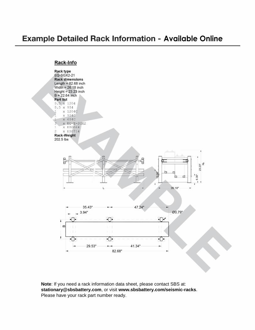
Available Online
Note: If you need a rack information data sheet, please contact SBS at:
[email protected], or visit www.sbsbattery.com/seismic-racks.
Please have your rack part number ready.
Step 2 -
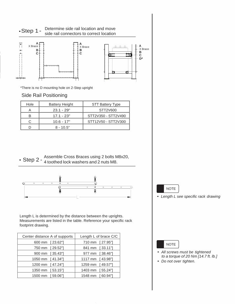
■ Step 1 - Determine side rail location and move
side rail connectors to correct location
A X Brace
B C
A X Brace
B C
A X Brace
B C D*
*There is no D mounting hole on 2-Step upright
Side Rail Positioning
Hole Battery Height STT Battery Type
A 23.1 - 29" STT2V600
B 17.1 - 23" STT2V350 - STT2V490
C 10.6 - 17" STT12V50 - STT2V300
D 8 - 10.5"
Assemble Cross Braces using 2 bolts M8x20, ■
4 toothed lock washers and 2 nuts M8.
• Length L see specific rack drawing
Length L is determined by the distance between the uprights.
Measurements are listed in the table. Reference your specific rack
footprint drawing.
• All screws must be tightened
• Do not over tighten.
to a torque of 20 Nm [14.7 ft. lb.]
NOTE
NOTE
Center distance A of supports Length L of brace C/C
600 mm [ 23.62"] 710 mm [ 27.95"]
750 mm [ 29.52"] 841 mm [ 33.11"]
900 mm [ 35.43"] 977 mm [ 38.46"]
1050 mm [ 41.34"] 1117 mm [ 43.98"]
1200 mm [ 47.24"] 1259 mm [ 49.57"]
1350 mm [ 53.15"] 1403 mm [ 55.24"]
1500 mm [ 59.06"] 1548 mm [ 60.94"]
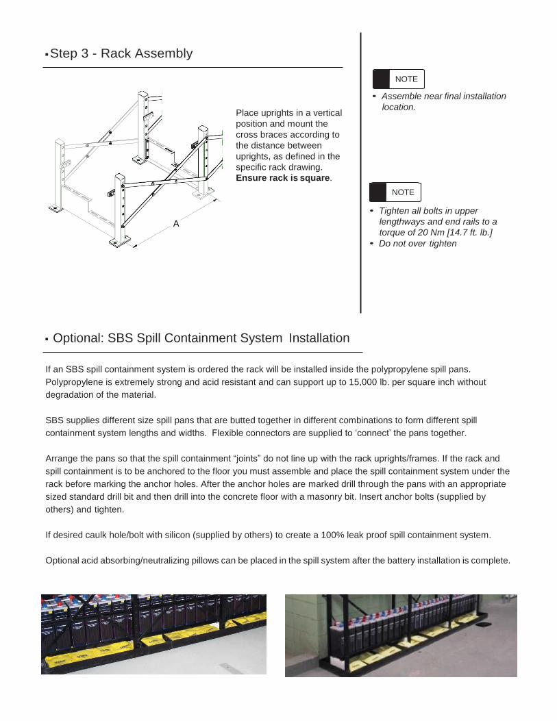
■ Step 3 - Rack Assembly
Place uprights in a vertical
position and mount the
cross braces according to
the distance between
uprights, as defined in the
specific rack drawing.
Ensure rack is square.
• Assemble near final installation
location.
• Tighten all bolts in upper
lengthways and end rails to a
torque of 20 Nm [14.7 ft. lb.]
• Do not over tighten
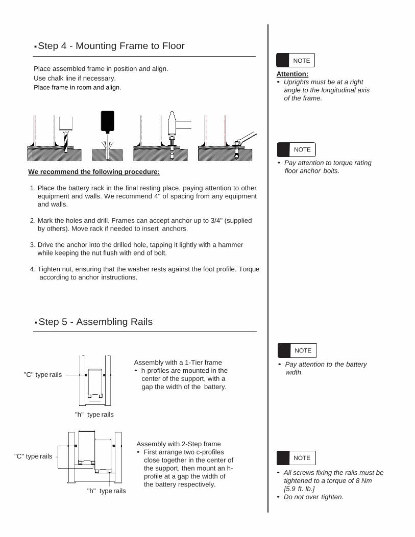
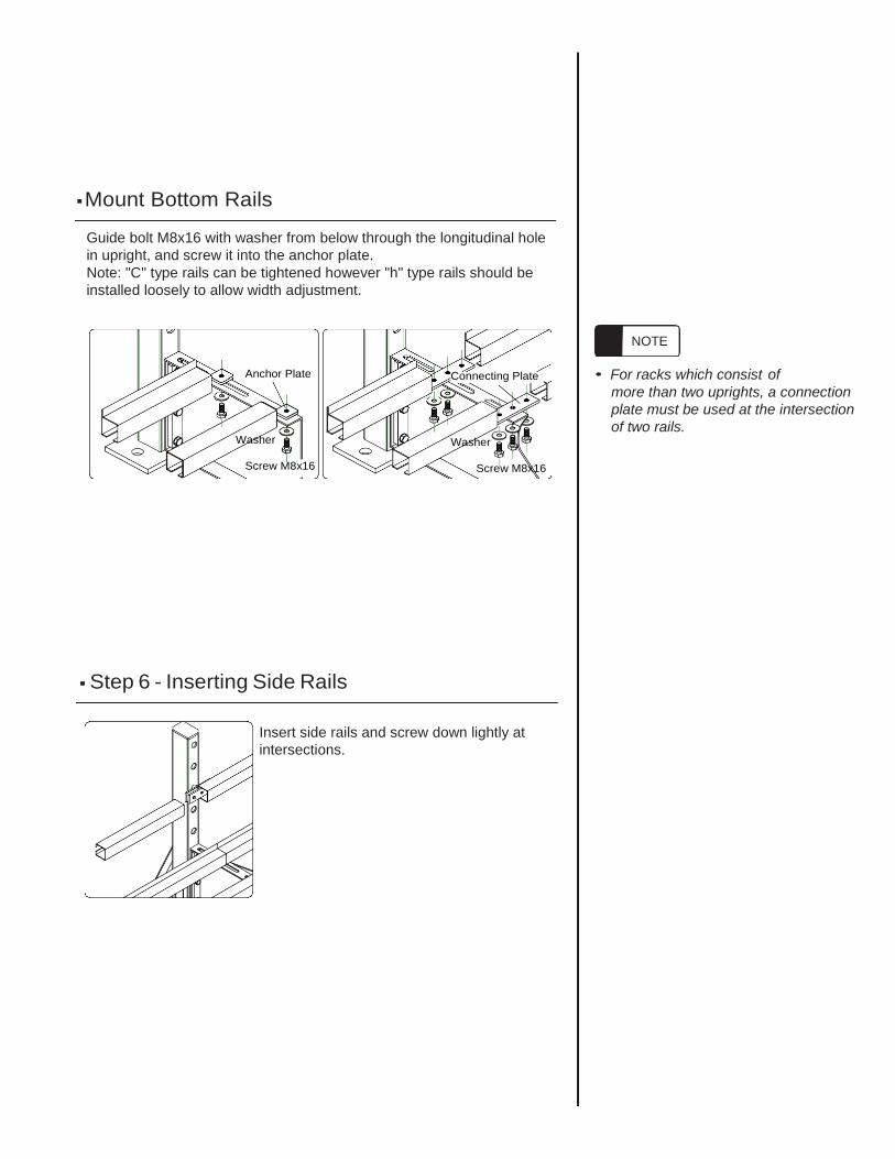
■ Optional: SBS Spill Containment System Installation
If an SBS spill containment system is ordered the rack will be installed inside the polypropylene spill pans.
Polypropylene is extremely strong and acid resistant and can support up to 15,000 lb. per square inch without
degradation of the material.
SBS supplies different size spill pans that are butted together in different combinations to form different spill
containment system lengths and widths. Flexible connectors are supplied to ‘connect’ the pans together.
Arrange the pans so that the spill containment “joints” do not line up with the rack uprights/frames. If the rack and
spill containment is to be anchored to the floor you must assemble and place the spill containment system under the
rack before marking the anchor holes. After the anchor holes are marked drill through the pans with an appropriate
sized standard drill bit and then drill into the concrete floor with a masonry bit. Insert anchor bolts (supplied by
others) and tighten.
If desired caulk hole/bolt with silicon (supplied by others) to create a 100% leak proof spill containment system.
Optional acid absorbing/neutralizing pillows can be placed in the spill system after the battery installation is complete.
NOTE
A
NOTE
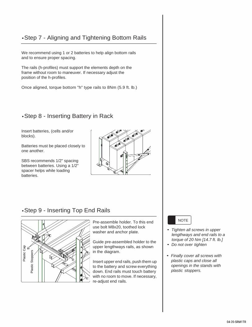
■ Step 4 - Mounting Frame to Floor
Place assembled frame in position and align.
Use chalk line if necessary.
Place frame in room and align.
We recommend the following procedure:
1. Place the battery rack in the final resting place, paying attention to other
equipment and walls. We recommend 4" of spacing from any equipment
and walls.
2. Mark the holes and drill. Frames can accept anchor up to 3/4" (supplied
by others). Move rack if needed to insert anchors.
3. Drive the anchor into the drilled hole, tapping it lightly with a hammer
while keeping the nut flush with end of bolt.
4. Tighten nut, ensuring that the washer rests against the foot profile. Torque
according to anchor instructions.
■ Step 5 - Assembling Rails
Attention:
• Uprights must be at a right
angle to the longitudinal axis
of the frame.
• Pay attention to torque rating
floor anchor bolts.
"C" type rails
"h" type rails
Assembly with a 1-Tier frame
• h-profiles are mounted in the
center of the support, with a
gap the width of the battery.
• Pay attention to the battery
width.
"C" type rails
"h" type rails
Assembly with 2-Step frame
• First arrange two c-profiles
close together in the center of
the support, then mount an h-
profile at a gap the width of
the battery respectively.
• All screws fixing the rails must be
tightened to a torque of 8 Nm
[5.9 ft. lb.]
• Do not over tighten.
NOTE
NOTE
NOTE
NOTE
■ Mount Bottom Rails
Guide bolt M8x16 with washer from below through the longitudinal hole
in upright, and screw it into the anchor plate.
Note: "C" type rails can be tightened however "h" type rails should be
installed loosely to allow width adjustment.
Anchor Plate
Washer
Screw M8x16
■ Step 6 - Inserting Side Rails
Connecting Plate
Washer
Screw M8x16
• For racks which consist of
more than two uprights, a connection
plate must be used at the intersection
of two rails.
Insert side rails and screw down lightly at
intersections.
NOTE
■ Step 7 - Aligning and Tightening Bottom Rails
We recommend using 1 or 2 batteries to help align bottom rails
and to ensure proper spacing.
The rails (h-profiles) must support the elements depth on the
frame without room to maneuver. If necessary adjust the
position of the h-profiles.
Once aligned, torque bottom "h" type rails to 8Nm (5.9 ft. lb.)
■ Step 8 - Inserting Battery in Rack
Insert batteries, (cells and/or
blocks).
Batteries must be placed closely to
one another.
SBS recommends 1/2" spacing
between batteries. Using a 1/2"
spacer helps while loading
batteries.
■ Step 9 - Inserting Top End Rails
Pre-assemble holder. To this end
use bolt M8x20, toothed lock
washer and anchor plate.
Guide pre-assembled holder to the
upper lengthways rails, as shown
in the diagram.
Insert upper end rails, push them up
to the battery and screw everything
down. End rails must touch battery
with no room to move. If necessary,
re-adjust end rails.
• Tighten all screws in upper
lengthways and end rails to a
torque of 20 Nm [14.7 ft. lb.]
• Do not over tighten
• Finally cover all screws with
plastic caps and close all
openings in the stands with
plastic stoppers.
NOTE
Pla
stic C
ap
Pla
stic S
toppe
rs
04-20-SRM1TR