Embed Size (px)
Citation preview

Seismic Arrays
presented at the
WORKSHOP
High Quality Seismic Stations and Networks for Small Budgets Volcan, Panama 8-13. March 2004by
Jens Havskov, Department of Earth Science
University of Bergen
Norway

0 0.5 1 1.5 2 2.5
TIME s
S1
S2
S3
S4
S5
S6
S7
S8
S9
A plane wavefront arrives with apparent slowness p to a rectangular shaped array (the intersection of the wavefront with the surface, where the array is installed, is shown). The angle with respect to North defines the ray arrival azimuth. Right: The waveforms recorded are ideally identical, except for the relative delays. In practice, they present differences due to the added noise and to the local ground heterogeneity

A projection on the incidence vertical plane. As the wavefront advances a distance cΔt, the intersection with the horizontal plane advances Δx, with apparent velocity v. The relations between v and c can be seen from the geometry in the figur as v = c/sin(i)

-2000 -1000 0 1000 2000
-2000
-1000
0
1000
2000
m
ARCES is a small aperture array with 25 stations covering four concentric circles. The diameter of the external ring is about 3 km. The radial spacing of the stations is not uniform in order to deal with different wavelength


Determination of azimuth and apparent velocity with Chiriqui array

-2000 -1000 0 1000 2000
-2000
-1000
0
1000
2000
m
-300 -200 -100 0 100 200 300
0
100
200
300
m
-25 -20 -15 -10 -5 0 5 10 15 20
wavenumber kx (1/km)
-25
-20
-15
-10
-5
0
5
10
15
20
wav
enu
mb
er k
y (1
/km
)
-50 -40 -30 -20 -10 0 10 20 30 40
wavenumber kx (1/km)
-50
-40
-30
-20
-10
0
10
20
30
40
wav
enu
mb
er k
y (1
/km
)0.1
0.2
0.3
0.4
0.5
0.6
0.7
0.8
0.9
1
1.2
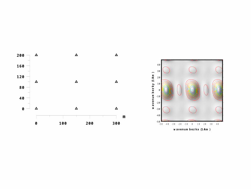
Arrray response function
0 100 200 300
0
40
80
120
160
200
m-50 -40 -30 -20 -10 0 10 20 30 40
wavenumber kx (1/km)
-50
-40
-30
-20
-10
0
10
20
30
40
wav
enu
mb
er k
y (1
/km
)
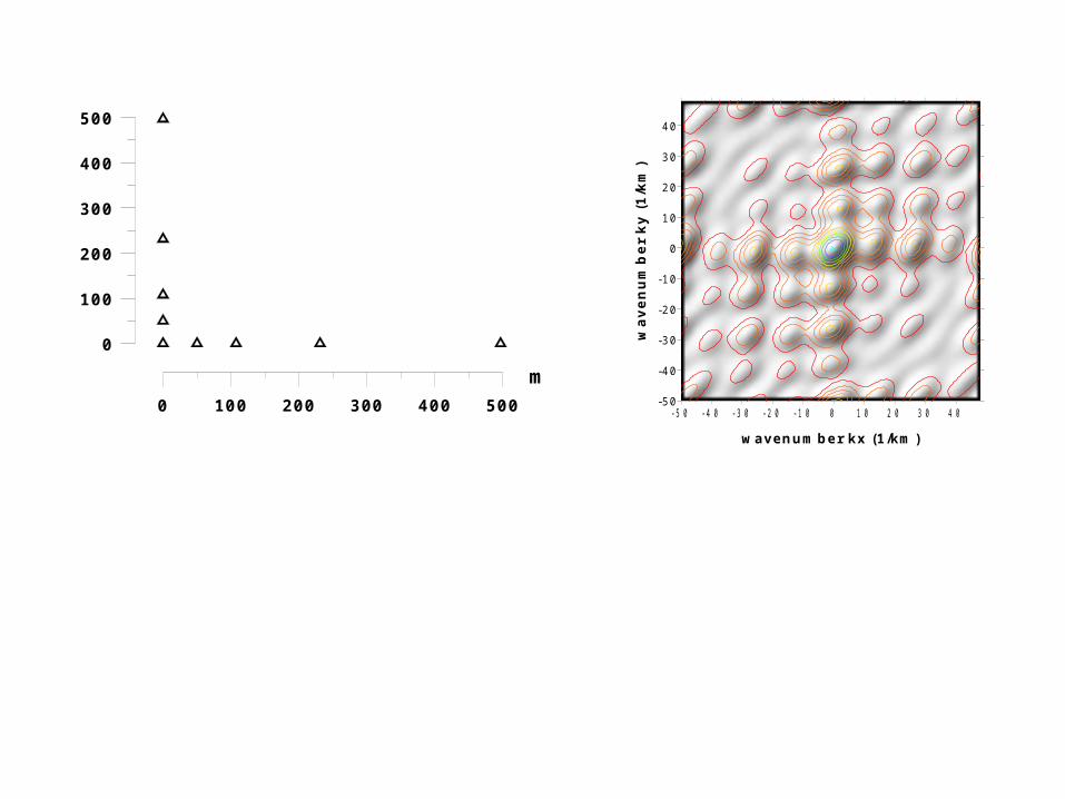
0 100 200 300 400 500
0
100
200
300
400
500
m
-50 -40 -30 -20 -10 0 10 20 30 40
wavenumber kx (1/km)
-50
-40
-30
-20
-10
0
10
20
30
40
wav
enu
mb
er k
y (1
/km
)

-400-2000200400
-100
0
100
200
300
m-50 -40 -30 -20 -10 0 10 20 30 40
wavenumber kx (1/km)
-50
-40
-30
-20
-10
0
10
20
30
40
wav
enu
mb
er k
y (1
/km
)

Block diagram of a portable array. It is composed of several modules, one of which is represented. A central box contains an 8-channels antialias filter, a 16 bit-digitizer, a GPS receiver and a power supply for all. The digitizer is controlled by a PC through the parallel port and is synchronized to the GPS time via the serial port. The seismometers have a preamplifier with a low-impedance differential output, so that long connection cables may be used. The recording is made on the PC hard disk.


Potential use of a small seismic array
Improved detection of weak signals
Automatic detection of P and S-wave arrivals
Determination of azimuth
Automatic location
Location of weak emergent arrivals like volcanic tremor
Building a regional location capability in a small area