Embed Size (px)
Citation preview
7/23/2019 Seismic Design EC8
http://slidepdf.com/reader/full/seismic-design-ec8 1/15
HOW TO MODEL EARTHQUAKE ACCORDING TO EC8 IN
AUTODESK ROBOT STRUCTURAL ANALISYS 2011
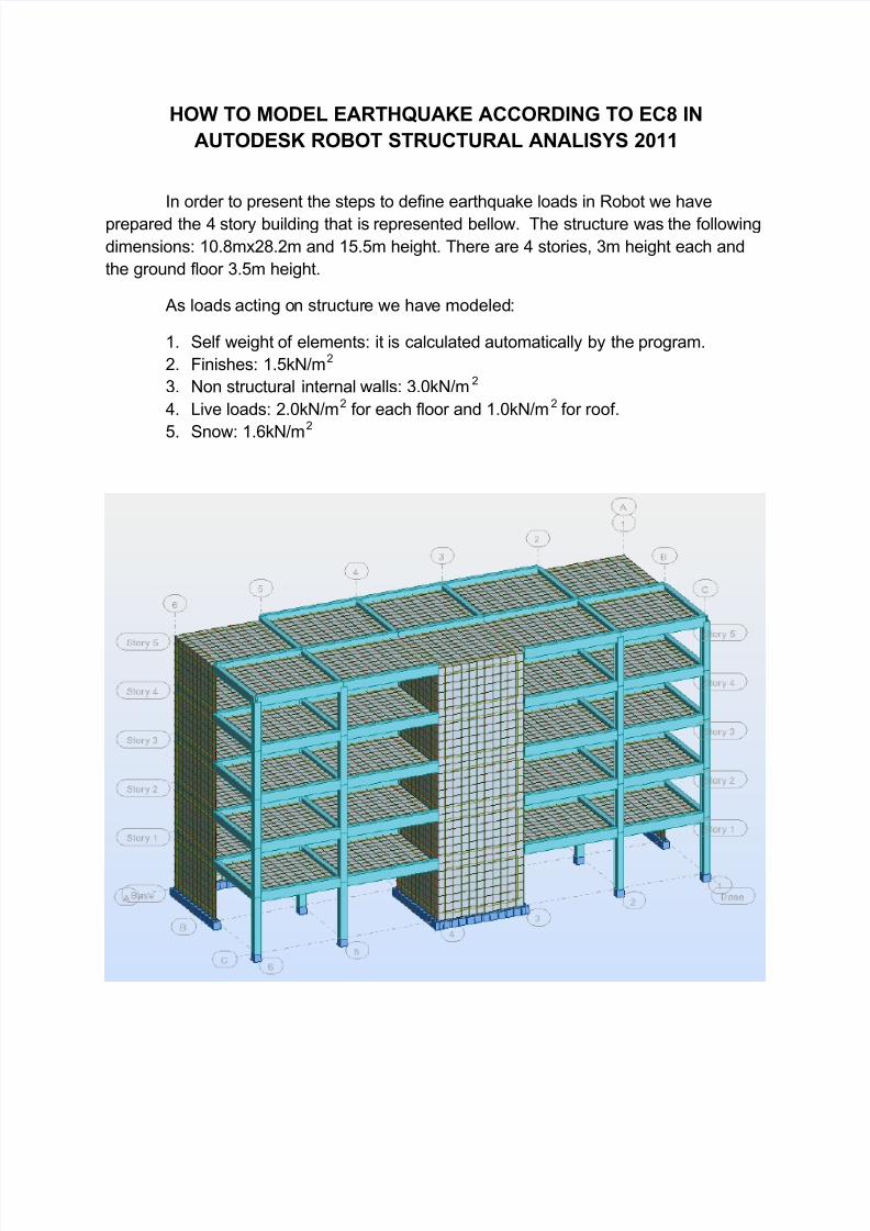
In order to present the steps to define earthquake loads in Robot we have
prepared the 4 story building that is represented bellow. The structure was the following
dimensions: 10.8mx28.2m and 15.5m height. There are 4 stories, 3m height each and
the ground floor 3.5m height.
As loads acting on structure we have modeled:
1. Self weight of elements: it is calculated automatically by the program.
2. Finishes: 1.5kN/m2
3. Non structural internal walls: 3.0kN/m2
4. Live loads: 2.0kN/m2 for each floor and 1.0kN/m2 for roof.
5. Snow: 1.6kN/m2
7/23/2019 Seismic Design EC8
http://slidepdf.com/reader/full/seismic-design-ec8 2/15
After completing the modeling of the geometry and loads it is time to define
earthquake loads. In Robot there are implemented many codes for earthquake. In our
case we used EN1998-1-1:2004.
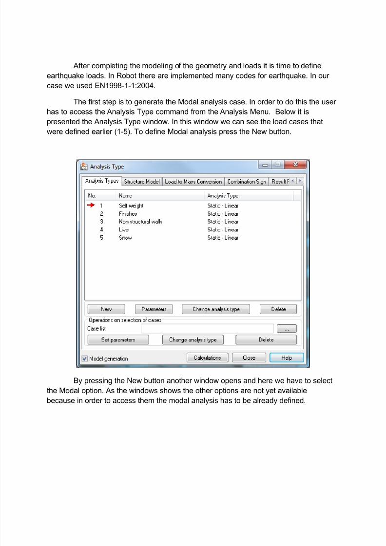
The first step is to generate the Modal analysis case. In order to do this the user
has to access the Analysis Type command from the Analysis Menu. Below it is
presented the Analysis Type window. In this window we can see the load cases that
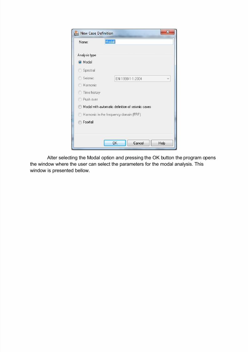
were defined earlier (1-5). To define Modal analysis press the New button.
By pressing the New button another window opens and here we have to selectthe Modal option. As the windows shows the other options are not yet available
because in order to access them the modal analysis has to be already defined.
7/23/2019 Seismic Design EC8
http://slidepdf.com/reader/full/seismic-design-ec8 3/15
Alter selecting the Modal option and pressing the OK button the program opens
the window where the user can select the parameters for the modal analysis. This
window is presented bellow.
7/23/2019 Seismic Design EC8
http://slidepdf.com/reader/full/seismic-design-ec8 4/15
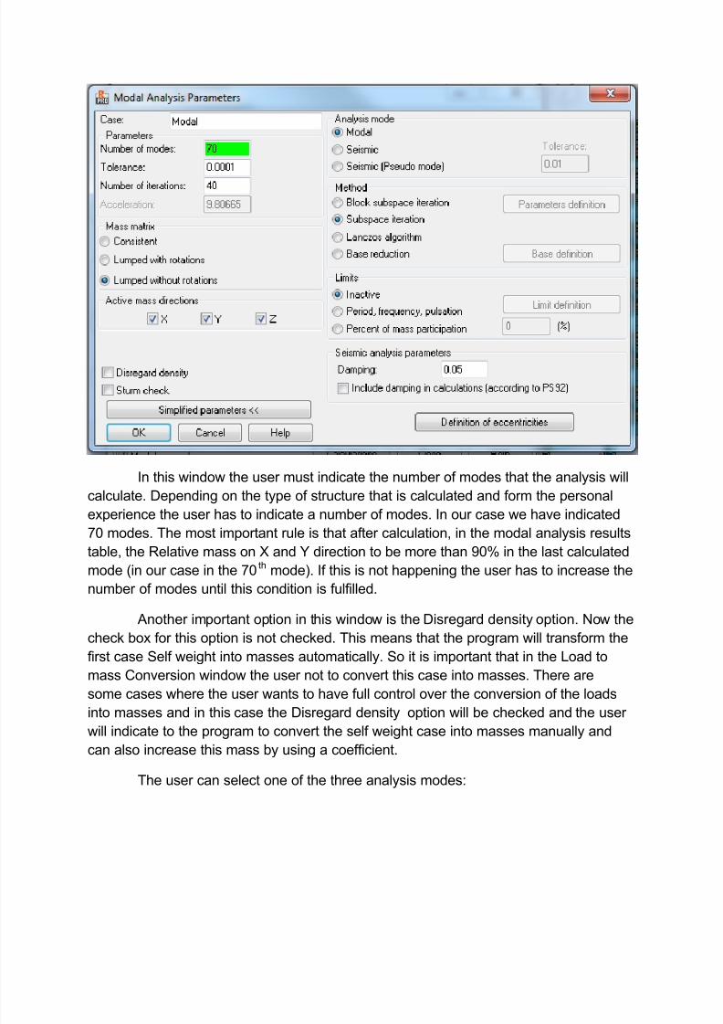
In this window the user must indicate the number of modes that the analysis will
calculate. Depending on the type of structure that is calculated and form the personal
experience the user has to indicate a number of modes. In our case we have indicated
70 modes. The most important rule is that after calculation, in the modal analysis resultstable, the Relative mass on X and Y direction to be more than 90% in the last calculated
mode (in our case in the 70th
mode). If this is not happening the user has to increase the
number of modes until this condition is fulfilled.
Another important option in this window is the Disregard density option. Now the
check box for this option is not checked. This means that the program will transform the
first case Self weight into masses automatically. So it is important that in the Load to
mass Conversion window the user not to convert this case into masses. There are
some cases where the user wants to have full control over the conversion of the loads
into masses and in this case the Disregard density option will be checked and the userwill indicate to the program to convert the self weight case into masses manually and
can also increase this mass by using a coefficient.
The user can select one of the three analysis modes:
7/23/2019 Seismic Design EC8
http://slidepdf.com/reader/full/seismic-design-ec8 5/15
Analysis Mode - modal
The modal analysis of the structure will be conducted. n vibration modes will befound, the iterations will be completed if a convergence condition is reached.
Activation of Sturm Check, which allows for searching for the omittedpulsations, is possible.
Analysis Mode - seismic
During modal structure analysis, n vibration modes will be selected (notnecessarily in the appropriate order). Those eigenvibration modes will be set, which areimportant to seismic analyses, therefore those which are characterized by a large massparticipation factor.
A Sturm Check is not possible for this structure analysis mode.
Analysis Mode - seismic pseudomodal
Spectral and seismic analysis will be conducted using the pseudomodalmethod. This should be used only when applying classic analysis methods based onmodal decomposition results in a very long structure analysis time.
The recommended option is the modal as we selected in our model. The othertwo options are useful when there are problems with reaching the 90% relative masscondition.
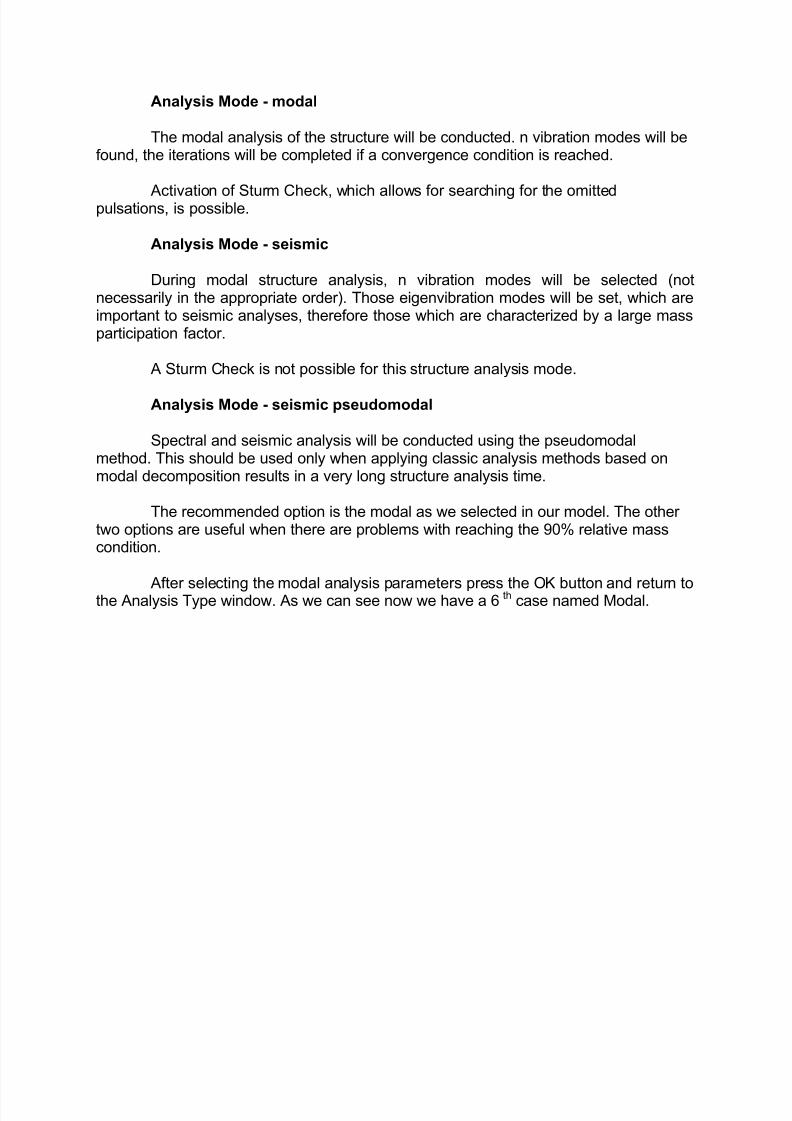
After selecting the modal analysis parameters press the OK button and return tothe Analysis Type window. As we can see now we have a 6th case named Modal.
7/23/2019 Seismic Design EC8
http://slidepdf.com/reader/full/seismic-design-ec8 6/15
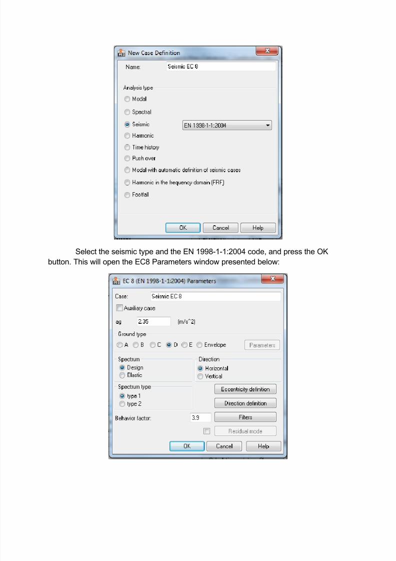
The next step is to generate the seismic analysis case. Press the New button
and see the New Case Definition window. Now, after defining the Modal case, there are
available all the other analysis types.
7/23/2019 Seismic Design EC8
http://slidepdf.com/reader/full/seismic-design-ec8 7/15
Select the seismic type and the EN 1998-1-1:2004 code, and press the OK
button. This will open the EC8 Parameters window presented below:
7/23/2019 Seismic Design EC8
http://slidepdf.com/reader/full/seismic-design-ec8 8/15
Parameters of a structure seismic analysis depend on a seismic code used
during calculations of a structure influenced by seismic impact.
The code dependant factors are editable for EN 1998-1-1:2004 General code;their values can be changed in the national annexes.
To complete the seismic analysis according to the rules given in a code, definethe following parameters.
· Value of the ag coefficient = 2.35m/s2
· Behavior factor q (see the tables 1, 2, 3 and 4 of the code) = 3.9
· Spectrum (design, elastic) = Design
· Spectrum type (type 1, type 2) = type 1
· Direction (horizontal, vertical) = Horizontal
· Ground type (A,B,C,D,E,Envelope) = D
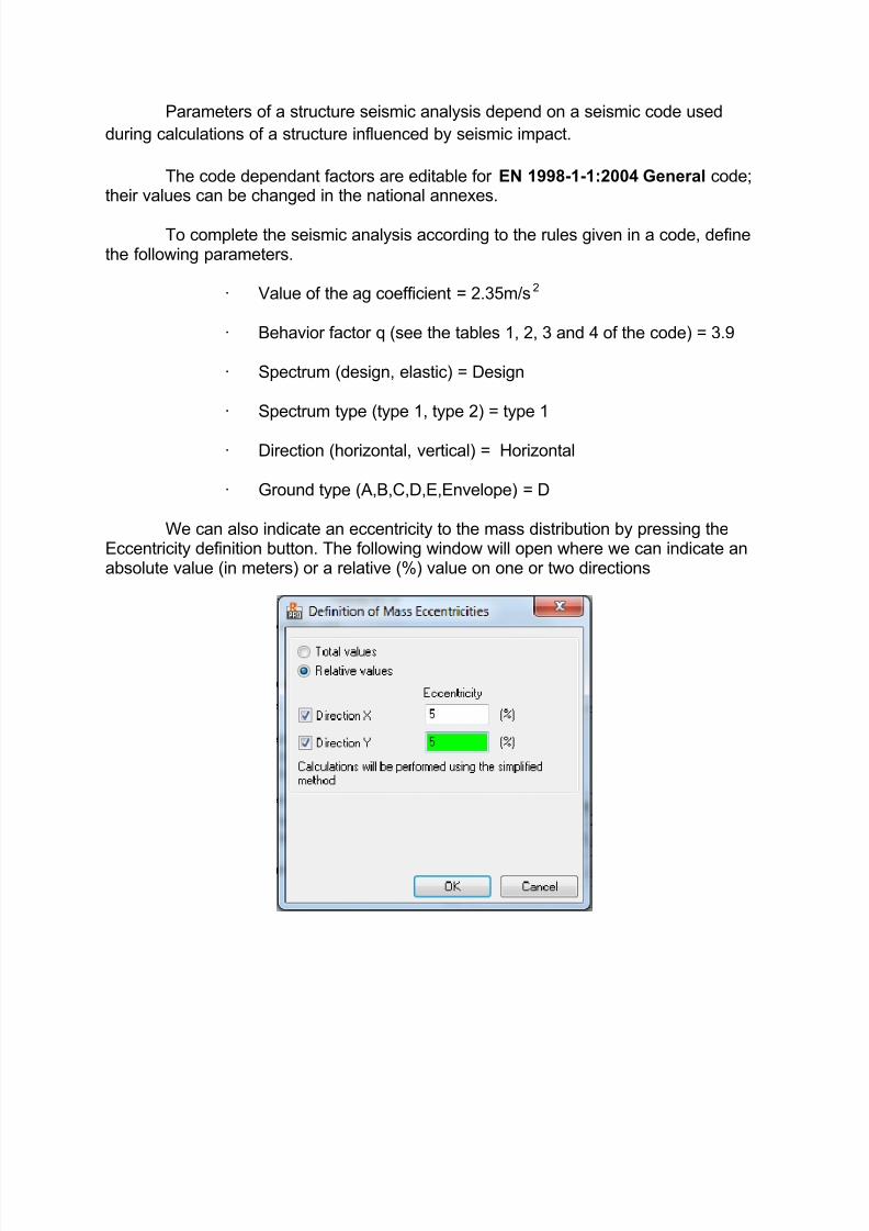
We can also indicate an eccentricity to the mass distribution by pressing theEccentricity definition button. The following window will open where we can indicate anabsolute value (in meters) or a relative (%) value on one or two directions
7/23/2019 Seismic Design EC8
http://slidepdf.com/reader/full/seismic-design-ec8 9/15
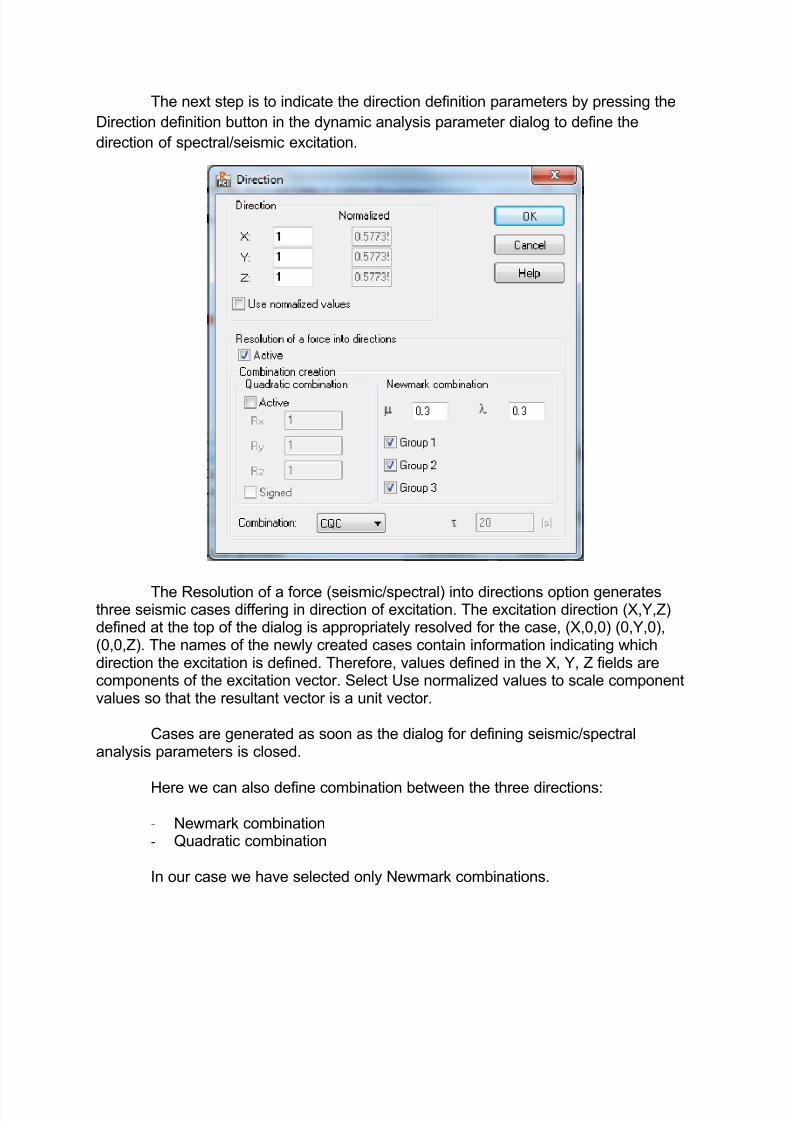
The next step is to indicate the direction definition parameters by pressing the
Direction definition button in the dynamic analysis parameter dialog to define the
direction of spectral/seismic excitation.
The Resolution of a force (seismic/spectral) into directions option generatesthree seismic cases differing in direction of excitation. The excitation direction (X,Y,Z)defined at the top of the dialog is appropriately resolved for the case, (X,0,0) (0,Y,0),(0,0,Z). The names of the newly created cases contain information indicating whichdirection the excitation is defined. Therefore, values defined in the X, Y, Z fields arecomponents of the excitation vector. Select Use normalized values to scale componentvalues so that the resultant vector is a unit vector.
Cases are generated as soon as the dialog for defining seismic/spectralanalysis parameters is closed.
Here we can also define combination between the three directions:
- Newmark combination- Quadratic combination
In our case we have selected only Newmark combinations.
7/23/2019 Seismic Design EC8
http://slidepdf.com/reader/full/seismic-design-ec8 10/15
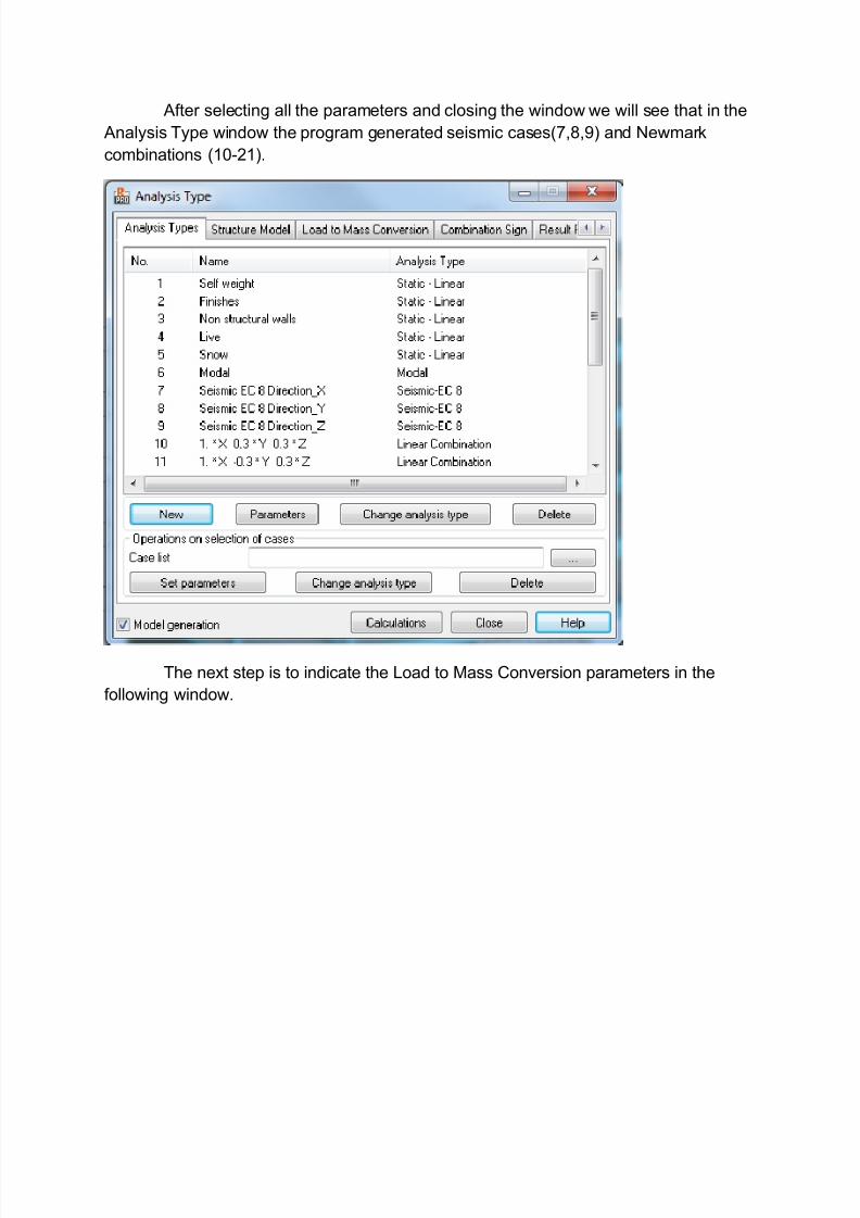
After selecting all the parameters and closing the window we will see that in the
Analysis Type window the program generated seismic cases(7,8,9) and Newmark
combinations (10-21).
The next step is to indicate the Load to Mass Conversion parameters in the
following window.
7/23/2019 Seismic Design EC8
http://slidepdf.com/reader/full/seismic-design-ec8 11/15
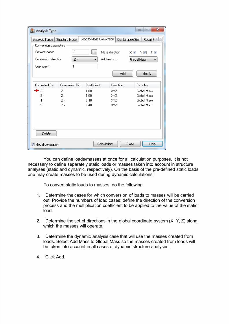
You can define loads/masses at once for all calculation purposes. It is notnecessary to define separately static loads or masses taken into account in structure
analyses (static and dynamic, respectively). On the basis of the pre-defined static loadsone may create masses to be used during dynamic calculations.
To convert static loads to masses, do the following.
1. Determine the cases for which conversion of loads to masses will be carriedout. Provide the numbers of load cases; define the direction of the conversionprocess and the multiplication coefficient to be applied to the value of the staticload.
2. Determine the set of directions in the global coordinate system (X, Y, Z) along
which the masses will operate.
3. Determine the dynamic analysis case that will use the masses created fromloads. Select Add Mass to Global Mass so the masses created from loads willbe taken into account in all cases of dynamic structure analyses.
4. Click Add.
7/23/2019 Seismic Design EC8
http://slidepdf.com/reader/full/seismic-design-ec8 12/15
You can also delete or modify a load case as necessary.
Concentrated forces are automatically converted to concentrated masses,distributed loads to distributed masses, and moments to rotational masses. SelectLoads > Mass table to view converted masses in the table of masses. Mass values are
presented in the table as weight values (acceleration of gravity is applied). Massescreated due to the conversion process are marked CNV in the Memo field todifferentiate them from user defined masses. The mark denotes the origin of a mass forthe benefit of the conversion procedure.
Note:
Conversion of loads to masses is always carried out at the beginning ofcalculations. It begins with the removal of the masses generated during the previousconversion. The change of the contents of the MEMO field in the table of masses mayresult in a mass not being removed during conversion, which leads to duplication of
masses.
In the Added masses table, the Conversion of loads tab presents dataconcerning masses (read only and printable). Individual table columns are as follows.
· Converted case – a number and a name of a converted case.
· Conversion direction – depending on a selected direction X+ / Y+ / Z+ / X- / Y-/ Z-.
· Factor - a dimensionless coefficient.
· Mass direction - X, Y or Z.
· Case - a number of the modal case to which a load is converted or dynamic forall cases.
Now that all the parameters are indicated we can close the Analysis Type
window and perform a Calculation of the structure by selecting from Analysis menu the
Calculation command.
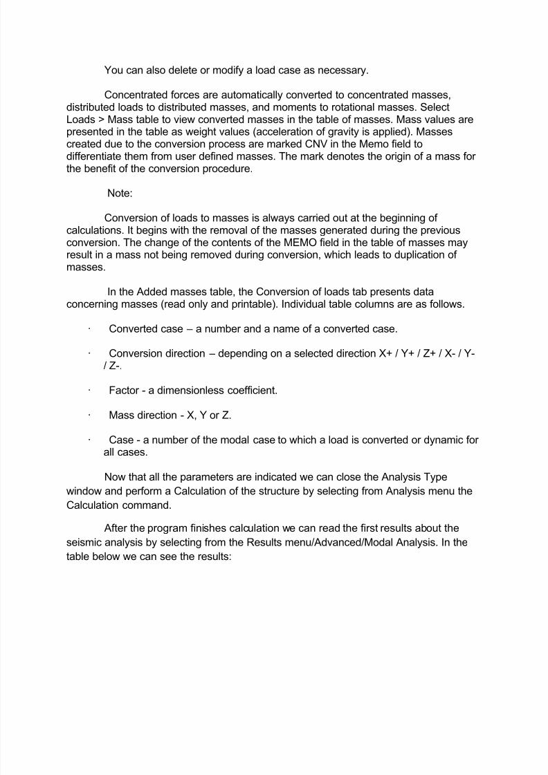
After the program finishes calculation we can read the first results about the
seismic analysis by selecting from the Results menu/Advanced/Modal Analysis. In thetable below we can see the results:
7/23/2019 Seismic Design EC8
http://slidepdf.com/reader/full/seismic-design-ec8 13/15
Here we can see that our structure has a period of 0.19 sec. This means that
the structure is very rigid.
7/23/2019 Seismic Design EC8
http://slidepdf.com/reader/full/seismic-design-ec8 14/15
Also we can see that the mass participation condition is fulfilled as in the 70th
mode we have 92.39% on X direction and 90.64% on Y direction (values indicated by
green circles). In the case that these values were less that 90% we would have to
change in the modal analysis parameter window the number of modes (increasing it)
and recalculate the structure until the condition is fulfilled.
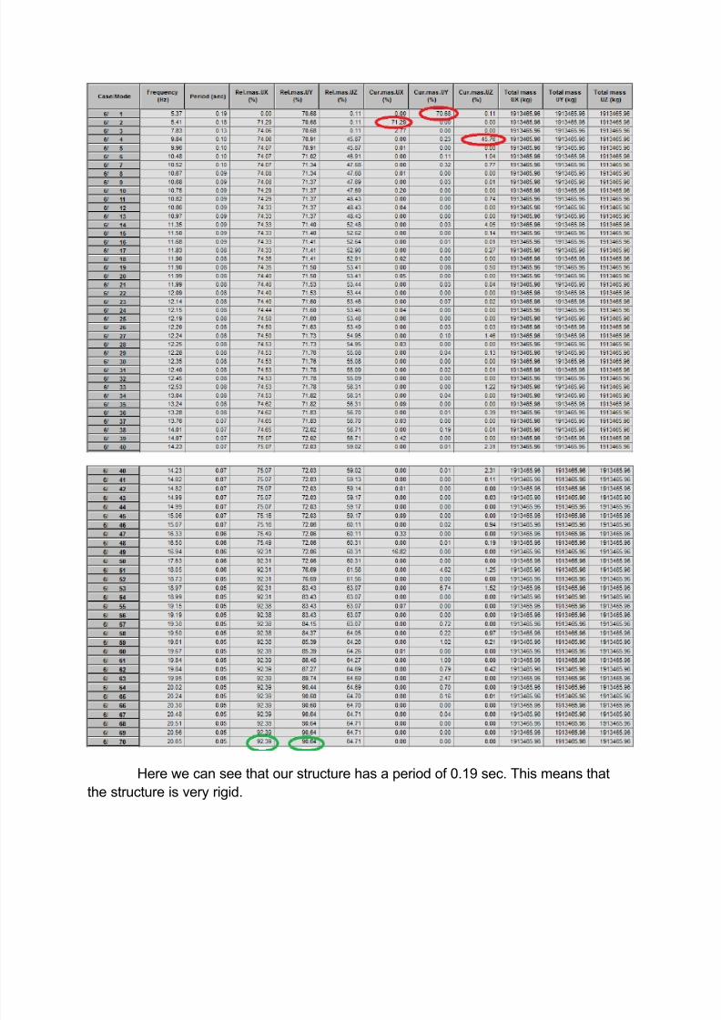
Before reading the results on bars there is one more important thing to do. We
have to indicate for each case the Combination Sign in the Analysis Type window.
The top part of the dialog consists of the following fields.
· Case - The number of a seismic or spectral analysis case
· Main mode –
The number of the main mode for determining the sign of thegiven combination.
Click Set to ascribe the selected mode to the seismic or spectral case.
The middle part of the dialog contains a table for the seismic and spectral analyses ofthe current structure. For each type of analysis, the table presents the following data.
7/23/2019 Seismic Design EC8
http://slidepdf.com/reader/full/seismic-design-ec8 15/15
· Case number
· Case name
· Main mode (user defined in the top of the dialog or 0) - The sign of the results
for this mode will be assumed for the entire combination.
If a main mode is set to 0, then the combination sign calculated from the formula forcalculating CQC or SRSS combinations will be assumed.
The bottom part of the dialog box selects the default type of calculations to be applied inthe case of seismic combination.
CQC - Complete Quadratic Combination
SRSS - Square Root of Sums of Squares
10% - 10% double sum
2SM - double sum.
In order to choose the main mode on each direction we have to return to the
Modal Analysis results table. Here we can see with red circles the values that indicates
the main modes for each direction.
The rule is to see for each direction which mode has the biggest value for
Current mass. In our case we can see that in the X direction we have in the 2nd
mode
71.29% , in the Y direction we have in the 1st mode 70.68% and in the Z direction wehave in the 4
th mode 45.76%.
With the definition of the main modes we have finished the modeling of the
seismic cases according to EN1998-1-1:2004. Now we can proceed to the design of the
structure elements.
![Midas Gen & Design+ 2021 v1.1 is now available! RELEASE ... 2021v1_1 Start...[Gen] Pushover Analysis Addition of new hinge curve as per EC8 : 2004 [Gen] Seismic Shear Design Improvement](https://img.pdfslide.net/doc/110x75/60a5443c46bc1177ee206e39/midas-gen-design-2021-v11-is-now-available-release-2021v11-start.jpg)
![SEISMIC PERFORMANCE OF MULTISTOREY STEEL FRAMES … · Norin Filip-Vacarescu 5 178 EC3 and EC8 with some special considerations from the Romanian seismic design code P100/2006[0]](https://img.pdfslide.net/doc/110x75/5e5c98531975b07f09615b3c/seismic-performance-of-multistorey-steel-frames-norin-filip-vacarescu-5-178-ec3.jpg)