Embed Size (px)
DESCRIPTION
GUIDELINE ONSEISMIC EVALUATIONAND UPGRADING OFNON-STRUCTURALBUILDING COMPONENTS
Citation preview
GUIDELINE ONSEISMIC EVALUATIONAND UPGRADING OFNON-STRUCTURAL
BUILDING COMPONENTS
December 1995
Research, Development and DemonstrationTechnology and Environment
Real Property ServicesOTTAWA, Ontario
K1A 0M2
Project Managers Telephone Fax E-MailMoe Cheung (613) 941-5581 (613) 941-5595 [email protected] Foo (613) 941-5550 (613) 941-5595 [email protected]
Additional Copies?
To obtain additional copies of this publication or to enquire about our other technical documents,please contact the RPS Documentation Centre at the address below:
Real Property Services' Documentation CentrePublic Works and Government Services CanadaRoom D-325, Sir Charles Tupper BuildingOttawa, Ontario K1A 0M2Fax No.: (613) 736-2029Telephone No.: (613) 736-2146
e-mail: [email protected]
Copyright © Public Works and Government Services Canada, 1995.All rights reserved. No part of this publication may be reproduced in any form, in an electronicretrieval system or otherwise, without the prior written permission of Public Works andGovernment Services Canada.
PWGSC Guideline on Seismic Evaluation and Upgrading of Non-Structural Building Components November, 1995
Preface
i
PREFACE
In designing earthquake-resistant buildings, there is a distinction between structural and non-structural design criteria. Structural design criteria for seismic effects aims at collapse prevention.Non-structural design criteria attempts to minimize the consequences of seismic hazards associatedwith non-load bearing building components upon life safety and property damage. One of the majorimpacts of recent earthquakes in Japan (1995 Kobe) and in the United States (1994 Northridge) onbuilding design practices was the extensive and costly damage due to non-structural buildingcomponents.
Retrofit measures for non-structural building components are directly related to life safety simplybecause most casualties are due to collapse and/or falling of non-load bearing building componentsduring or after earthquakes. Unsatisfactory nonstructural performance also leads to concerns forproperty damage and continuity of operation. There are national design codes and guidelines for thestructural design, evaluation and upgrading of buildings against earthquakes in Canada, similarstandards for non-structural components are not available. As one of the major custodiandepartments in the Federal Government, Public Works and Government Services Canada (PWGSC)decided to develop a comprehensive guideline for seismic retrofit of non-structural components ofoffice buildings.
In recognition of the need for a comprehensive national standard for the identification and reductionof such seismic hazards, PWGSC initiated the development of a guideline on the seismic evaluationand upgrading of non-structural building components. The guideline was developed in conjunctionwith the Institute for Research in Construction of the National Research Council of Canada(IRC/NRC) and the private sector. Dr. D.E. Allen of IRC/NRC, and Dr. W.E. McKevitt ofMcKevitt Engineering Ltd. in Vancouver who prepared the draft document, were the principalcontributors to the guideline development. Their contributions are gratefully appreciated.
PWGSC would also like to acknowledge Mr. M.S. Vézina of SNC-Lavalin in Montreal and Dr. J.H.Rainer of IRC/NRC for their review and comments of the guideline. The guideline was developed with close collaboration with the Pacific Western Region of PWGSC.Special thanks are due to Mr. B. White and Mr. J. Yong of PWGSC in Vancouver for their support,comments and suggestions, and for carrying out and evaluating a field demonstration in Vancouverusing the guideline.
PWGSC Guideline on Seismic Evaluation and Upgrading of Non-Structural Building Components November, 1995
Table of Contents
ii
TABLE OF CONTENTS
PagePREFACE . . . . . . . . . . . . . . . . . . . . . . . . . . . . . . . . . . . . . . . . . . . . . . . . . . . . . . . . . . . . . . . . . . . . . . . i
1. INTRODUCTION . . . . . . . . . . . . . . . . . . . . . . . . . . . . . . . . . . . . . . . . . . . . . . . . . . . . . . . . . . 11.1 Purpose of the Guideline . . . . . . . . . . . . . . . . . . . . . . . . . . . . . . . . . . . . . . . . . . . . . . . . 11.2 Scope . . . . . . . . . . . . . . . . . . . . . . . . . . . . . . . . . . . . . . . . . . . . . . . . . . . . . . . . . . . . . . 11.3 Application . . . . . . . . . . . . . . . . . . . . . . . . . . . . . . . . . . . . . . . . . . . . . . . . . . . . . . . . . . 11.4 Definitions . . . . . . . . . . . . . . . . . . . . . . . . . . . . . . . . . . . . . . . . . . . . . . . . . . . . . . . . . . 21.5 Performance Objectives . . . . . . . . . . . . . . . . . . . . . . . . . . . . . . . . . . . . . . . . . . . . . . . . 21.6 Background . . . . . . . . . . . . . . . . . . . . . . . . . . . . . . . . . . . . . . . . . . . . . . . . . . . . . . . . . 2
2. SEISMIC ACTIONS AND EFFECTS . . . . . . . . . . . . . . . . . . . . . . . . . . . . . . . . . . . . . . . . . . . 42.1 Seismic Actions . . . . . . . . . . . . . . . . . . . . . . . . . . . . . . . . . . . . . . . . . . . . . . . . . . . . . . 42.2 Seismic Effects . . . . . . . . . . . . . . . . . . . . . . . . . . . . . . . . . . . . . . . . . . . . . . . . . . . . . . . 62.3 Loads and Deflections (National Building Code 1995) . . . . . . . . . . . . . . . . . . . . . . . . . 112.4 Equipment Restraint Forces . . . . . . . . . . . . . . . . . . . . . . . . . . . . . . . . . . . . . . . . . . . . 122.5 Unreinforced Masonry Bearing-Wall Buildings . . . . . . . . . . . . . . . . . . . . . . . . . . . . . . 122.6 Low Seismicity . . . . . . . . . . . . . . . . . . . . . . . . . . . . . . . . . . . . . . . . . . . . . . . . . . . . . . 12
3. MITIGATION PRINCIPLES . . . . . . . . . . . . . . . . . . . . . . . . . . . . . . . . . . . . . . . . . . . . . . . . . 153.1 Main Approaches to Mitigation of Seismic Risk . . . . . . . . . . . . . . . . . . . . . . . . . . . . . 153.2 Techniques of Component Upgrading . . . . . . . . . . . . . . . . . . . . . . . . . . . . . . . . . . . . . 153.3 Risk Considerations . . . . . . . . . . . . . . . . . . . . . . . . . . . . . . . . . . . . . . . . . . . . . . . . . . 153.4 Behaviour Considerations . . . . . . . . . . . . . . . . . . . . . . . . . . . . . . . . . . . . . . . . . . . . . . 163.5 Other Considerations . . . . . . . . . . . . . . . . . . . . . . . . . . . . . . . . . . . . . . . . . . . . . . . . . 16
4. PROCEDURE FOR EVALUATION, UPGRADING DESIGN ANDMITIGATION PLANNING . . . . . . . . . . . . . . . . . . . . . . . . . . . . . . . . . . . . . . . . . . . . . . . . . . 194.1 Preliminary Evaluation . . . . . . . . . . . . . . . . . . . . . . . . . . . . . . . . . . . . . . . . . . . . . . . . 194.2 Performance Objectives for the Upgrading . . . . . . . . . . . . . . . . . . . . . . . . . . . . . . . . . . 204.3 Building Walk-Down: Inventory, Risk Assessment . . . . . . . . . . . . . . . . . . . . . . . . . . . 204.4 Mitigation Priorities . . . . . . . . . . . . . . . . . . . . . . . . . . . . . . . . . . . . . . . . . . . . . . . . . . 244.5 Component Evaluations . . . . . . . . . . . . . . . . . . . . . . . . . . . . . . . . . . . . . . . . . . . . . . . 254.6 Upgrading Techniques . . . . . . . . . . . . . . . . . . . . . . . . . . . . . . . . . . . . . . . . . . . . . . . . 254.7 Mitigation Plan . . . . . . . . . . . . . . . . . . . . . . . . . . . . . . . . . . . . . . . . . . . . . . . . . . . . . . 25
5. UPGRADING TECHNIQUES . . . . . . . . . . . . . . . . . . . . . . . . . . . . . . . . . . . . . . . . . . . . . . . . 265.1 Architectural Components . . . . . . . . . . . . . . . . . . . . . . . . . . . . . . . . . . . . . . . . . . . . . . 265.2 Components of Electrical and Mechanical Systems . . . . . . . . . . . . . . . . . . . . . . . . . . . 345.3 Building Contents . . . . . . . . . . . . . . . . . . . . . . . . . . . . . . . . . . . . . . . . . . . . . . . . . . . . 44
6. EXAMPLE APPLICATIONS . . . . . . . . . . . . . . . . . . . . . . . . . . . . . . . . . . . . . . . . . . . . . . . . . 50
REFERENCES . . . . . . . . . . . . . . . . . . . . . . . . . . . . . . . . . . . . . . . . . . . . . . . . . . . . . . . . . . . . . . . . . . 53APPENDIX A PRELIMINARY EVALUATION . . . . . . . . . . . . . . . . . . . . . . . . . . . . . . . . . . . . . . . . 54
PWGSC Guideline on Seismic Evaluation and Upgrading of Non-Structural Building Components November, 1995
Chapter 1
1
1. INTRODUCTION
1.1 Purpose of the Guideline
In recent years the importance of failure of non-structural building components during earthquake hasgenerated considerable concern. Experience is well documented of cases where the building structure hassurvived an earthquake with no damage but the facility is rendered unusable due to extensive non-structuraldamage. Risk to life safety of the occupants of the building from failure of the non-structural componentscan be considerable even when the building structure has performed well. The cost of non-structural damageis also far greater than previously expected. These costs include loss of function and disruption costs as wellas the costs for repair or replacement of damaged components and articles. Also the extent of non-structuraldamage to buildings in low seismic zones can be considerably greater than structural damage costs. Manybuildings throughout Canada were constructed before a full understanding of these risks existed and methodsto reduce such risks were well understood.
The Guideline was prepared to help engineers and architects evaluate non-structural building componentsfor seismic hazards and to recommend upgrading when such hazards exist. The Guideline may also be usedby building owners to help identify non-structural building components which may be potentially hazardous,but specific recommendations for seismic upgrading should be provided by a qualified engineer or architect.
1.2 Scope
This guideline addresses the risk due to failure of non-structural components during earthquake. The presentpublication restricts itself to normal office buildings and libraries and does not include sensitive equipmentor critical operations.
Other publications provide guidance on seismic screening and seismic evaluation of existing buildings (NRC1993-1, NRC 1993-2) as well as seismic upgrading of the building structure (NRC 1995).
1.3 Application
This document may be applied to existing buildings, including renovations of existing buildings. In the caseof building contents, it may also be applied to new buildings. It should not, however, be applied to verifycompliance of architectural building components in new buildings with the building code.
PWGSC Guideline on Seismic Evaluation and Upgrading of Non-Structural Building Components November, 1995
Chapter 1
2
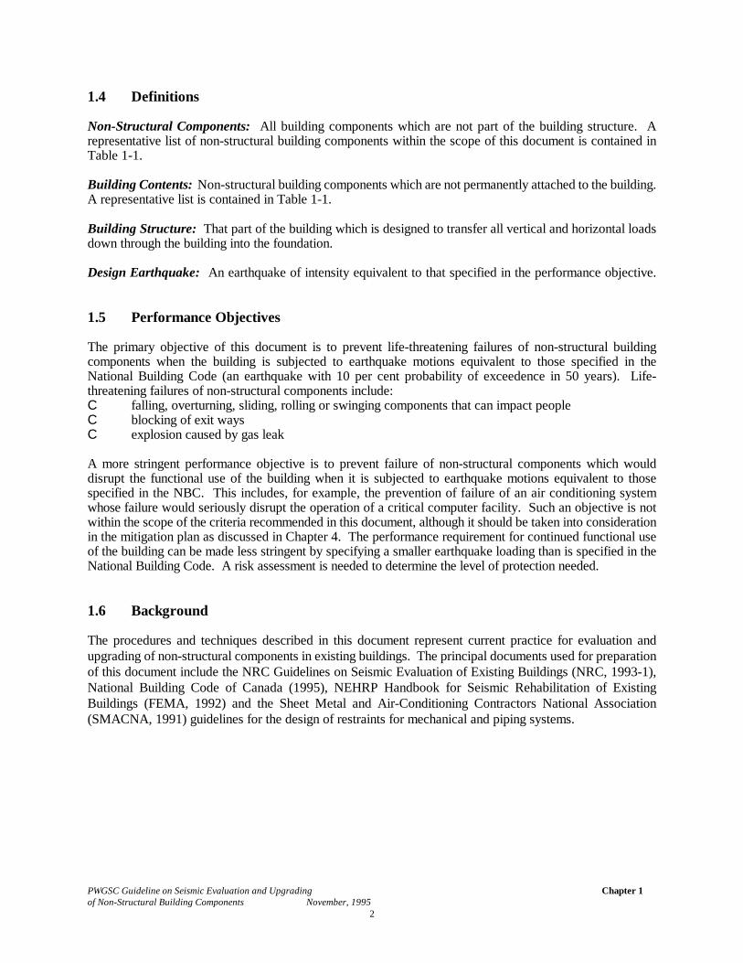
1.4 Definitions
Non-Structural Components: All building components which are not part of the building structure. Arepresentative list of non-structural building components within the scope of this document is contained inTable 1-1.
Building Contents: Non-structural building components which are not permanently attached to the building.A representative list is contained in Table 1-1.
Building Structure: That part of the building which is designed to transfer all vertical and horizontal loadsdown through the building into the foundation.
Design Earthquake: An earthquake of intensity equivalent to that specified in the performance objective.
1.5 Performance Objectives
The primary objective of this document is to prevent life-threatening failures of non-structural buildingcomponents when the building is subjected to earthquake motions equivalent to those specified in theNational Building Code (an earthquake with 10 per cent probability of exceedence in 50 years). Life-threatening failures of non-structural components include:C falling, overturning, sliding, rolling or swinging components that can impact peopleC blocking of exit waysC explosion caused by gas leak
A more stringent performance objective is to prevent failure of non-structural components which woulddisrupt the functional use of the building when it is subjected to earthquake motions equivalent to thosespecified in the NBC. This includes, for example, the prevention of failure of an air conditioning systemwhose failure would seriously disrupt the operation of a critical computer facility. Such an objective is notwithin the scope of the criteria recommended in this document, although it should be taken into considerationin the mitigation plan as discussed in Chapter 4. The performance requirement for continued functional useof the building can be made less stringent by specifying a smaller earthquake loading than is specified in theNational Building Code. A risk assessment is needed to determine the level of protection needed.
1.6 Background
The procedures and techniques described in this document represent current practice for evaluation andupgrading of non-structural components in existing buildings. The principal documents used for preparationof this document include the NRC Guidelines on Seismic Evaluation of Existing Buildings (NRC, 1993-1),National Building Code of Canada (1995), NEHRP Handbook for Seismic Rehabilitation of ExistingBuildings (FEMA, 1992) and the Sheet Metal and Air-Conditioning Contractors National Association(SMACNA, 1991) guidelines for the design of restraints for mechanical and piping systems.
PWGSC Guideline on Seismic Evaluation and Upgrading of Non-Structural Building Components November, 1995
Chapter 1
3
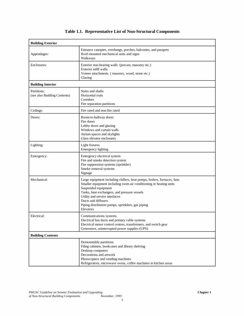
Table 1.1. Representative List of Non-Structural Components
Building Exterior
Appendages:Entrance canopies, overhangs, porches, balconies, and parapetsRoof-mounted mechanical units and signsWalkways
Enclosures: Exterior non-bearing walls (precast, masonry etc.)Exterior infill wallsVeneer attachments ( masonry, wood, stone etc.)Glazing
Building Interior
Partitions:(see also Building Contents)
Stairs and shaftsHorizontal exitsCorridorsFire separation partitions
Ceilings: Fire rated and non-fire rated
Doors: Room-to-hallway doorsFire doorsLobby doors and glazingWindows and curtain wallsAtrium spaces and skylightsGlass elevator enclosures
Lighting: Light fixturesEmergency lighting
Emergency: Emergency electrical systemFire and smoke detection systemFire suppression systems (sprinkler)Smoke removal systemsSignage
Mechanical: Large equipment including chillers, heat pumps, boilers, furnaces, fansSmaller equipment including room air conditioning or heating unitsSuspended equipmentTanks, heat exchangers, and pressure vesselsUtility and service interfacesDucts and diffusersPiping distribution pumps, sprinklers, gas pipingElevators
Electrical: Communications systemsElectrical bus ducts and primary cable systemsElectrical motor control centres, transformers, and switch gearGenerators, uninterrupted power supplies (UPS)
Building Contents
Demountable partitionsFiling cabinets, bookcases and library shelvingDesktop computersDecorations and artworkPhotocopiers and vending machinesRefrigerators, microwave ovens, coffee machines in kitchen areas
PWGSC Guideline on Seismic Evaluation and Upgrading of Non-Structural Building Components November, 1995
Chapter 2
4
2. SEISMIC ACTIONS AND EFFECTS
2.1 Seismic Actions
In considering the seismic actions for non-structural components, it is important to appreciate the seismicmotions of the structure to which the component is attached. Whether one is designing the structure of thebuilding or the non-structural components located within the building, the principles of earthquake resistantdesign are the same.
To assist in appreciating the interactive nature of the structural and component response, an elementarydiscussion is provided in this section.
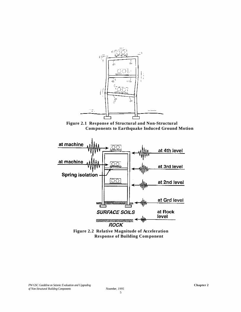
Figure 2.1 shows a schematic diagram of a structure and non-structural components responding to groundmotion induced by a strong earthquake. The response of the structure is normally classified as a multi-degree-of-freedom non-linear response, with non-linear effects developing from cracking and or yielding of thestructural members and connections. Additional non-linear effects are involved in the response of the systemdue to the inelastic contributions of the non-structural components in the building. This is true for virtually allstructures designed to the provisions of the National Building Code of Canada. The NBCC also assumes thatthere are non-linear effects in the response of all non-structural components and/or their connections to thestructure.
Figure 2.2 indicates the relative magnitude of the acceleration response for various components in a building. The ground acceleration on rock (or firm soil) is the ground acceleration specified by the code. A soilamplification factor is included in the code provisions to allow for the soil amplification as the seismic wavestravel through softer surface soils. The ground acceleration levels are further amplified in the buildingresponse to the ground movement. Generally the level of vibration increases with height within the buildingwith the highest accelerations occurring at roof level.
Components attached to the building respond to base excitation caused by the acceleration of the structure atthe point the component is attached. If the component is rigid and rigidly attached to the structure it willundergo acceleration of the same magnitude as the structure at the attachment point. Flexible componentsand/or components with flexible attachment to the structure will have a response which is amplified above theattachment point accelerations.
The response of a structure and attached components can be calculated using detailed computer models andnon-linear time-step integration procedures. However this is time consuming and expensive and requires ahigh degree of analytical expertise to obtain reliable results. The approach taken by the NBCC (Section 2.3 ofthis Guideline) is to use a simplified equivalent static force procedure to approximate the seismic forces appliedto the components and connections. The code method can be viewed as an upper bound to the forcemagnitudes which accounts for many complexities and variables involved in the seismic response of thecomponents.
PWGSC Guideline on Seismic Evaluation and Upgrading of Non-Structural Building Components November, 1995
Chapter 2
5
Figure 2.1 Response of Structural and Non-Structural Components to Earthquake Induced Ground Motion
Figure 2.2 Relative Magnitude of Acceleration Response of Building Component
PWGSC Guideline on Seismic Evaluation and Upgrading of Non-Structural Building Components November, 1995
Chapter 2
6
2.2 Seismic Effects
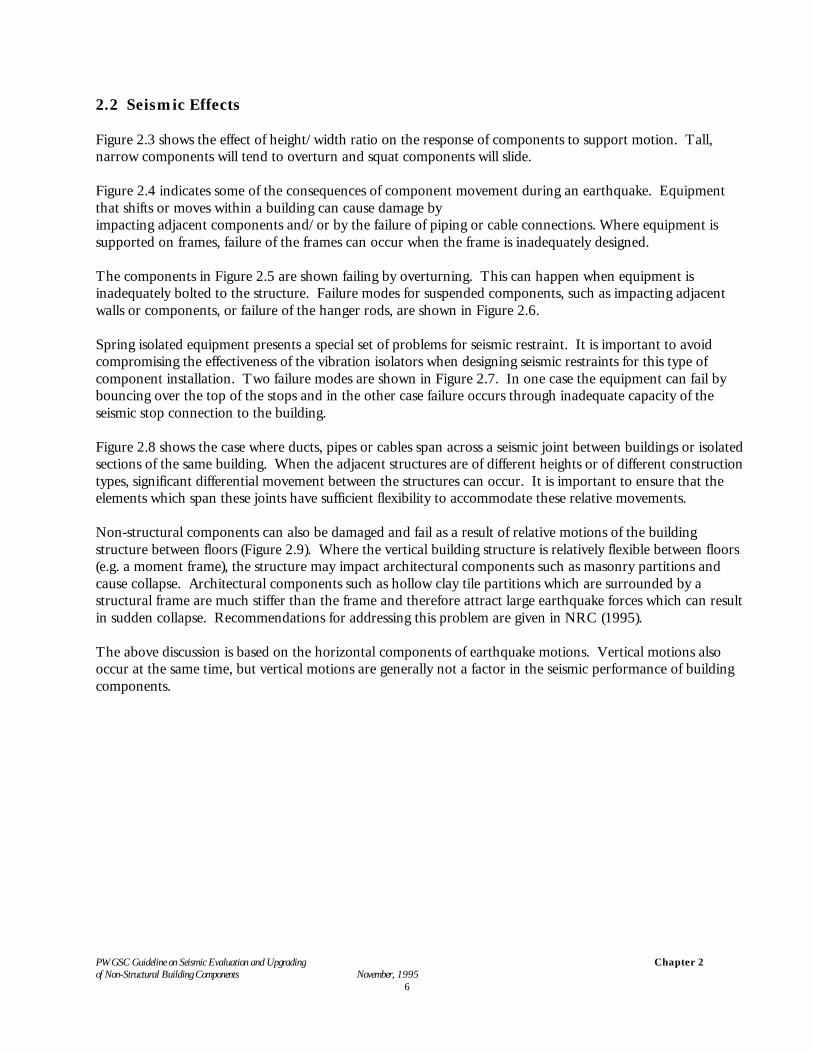
Figure 2.3 shows the effect of height/width ratio on the response of components to support motion. Tall,narrow components will tend to overturn and squat components will slide.
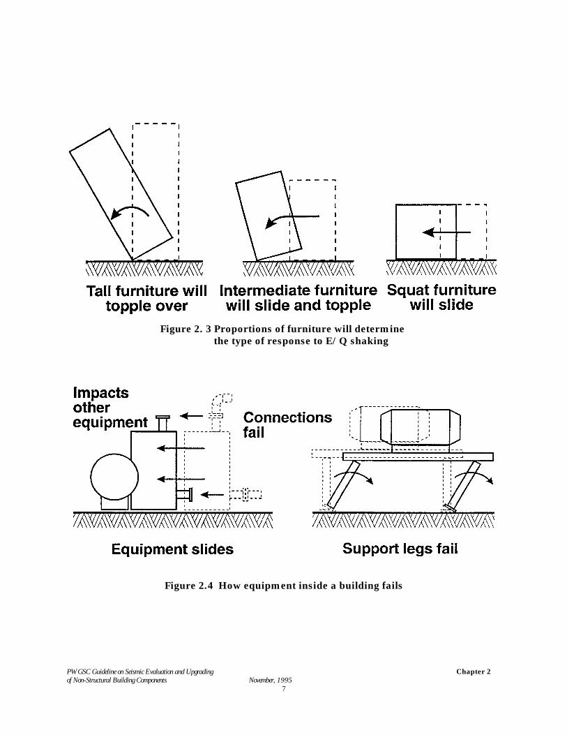
Figure 2.4 indicates some of the consequences of component movement during an earthquake. Equipmentthat shifts or moves within a building can cause damage by impacting adjacent components and/or by the failure of piping or cable connections. Where equipment issupported on frames, failure of the frames can occur when the frame is inadequately designed.
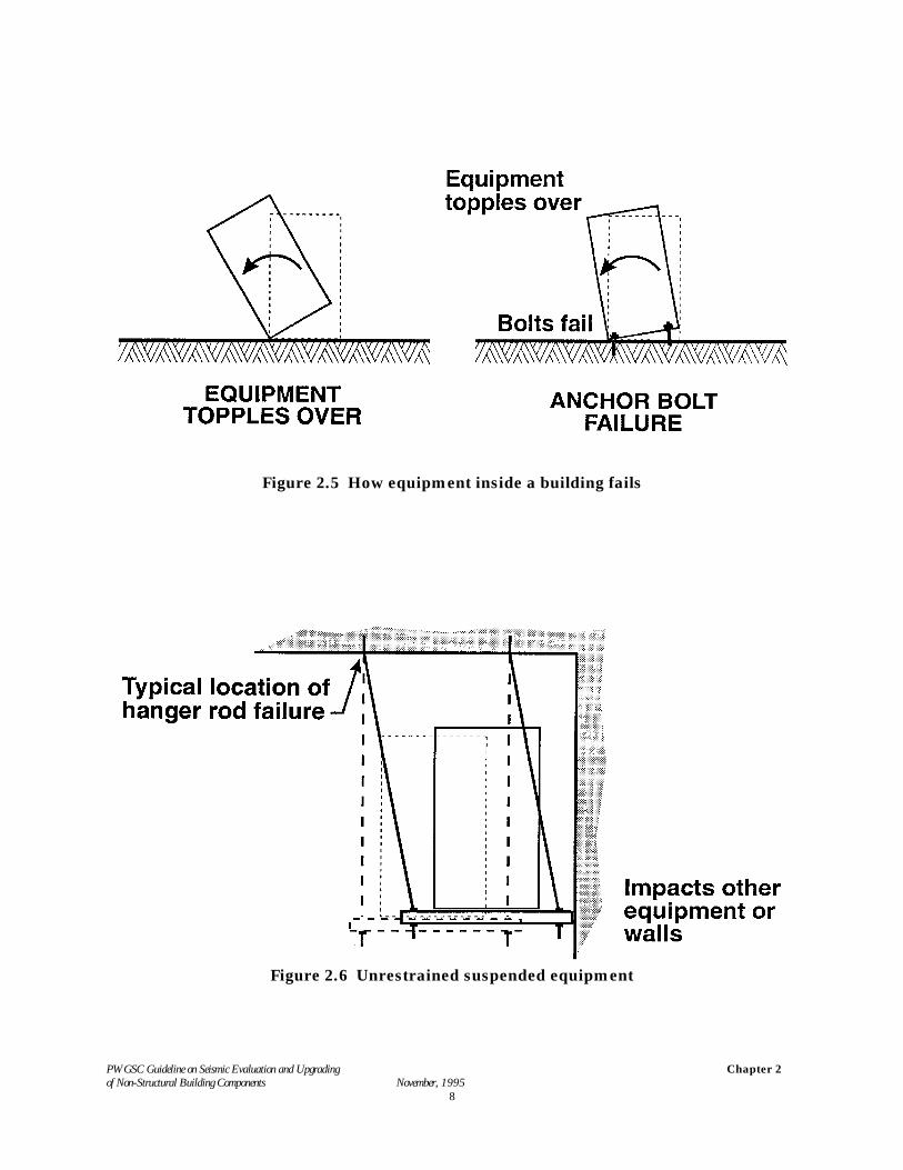
The components in Figure 2.5 are shown failing by overturning. This can happen when equipment isinadequately bolted to the structure. Failure modes for suspended components, such as impacting adjacentwalls or components, or failure of the hanger rods, are shown in Figure 2.6.
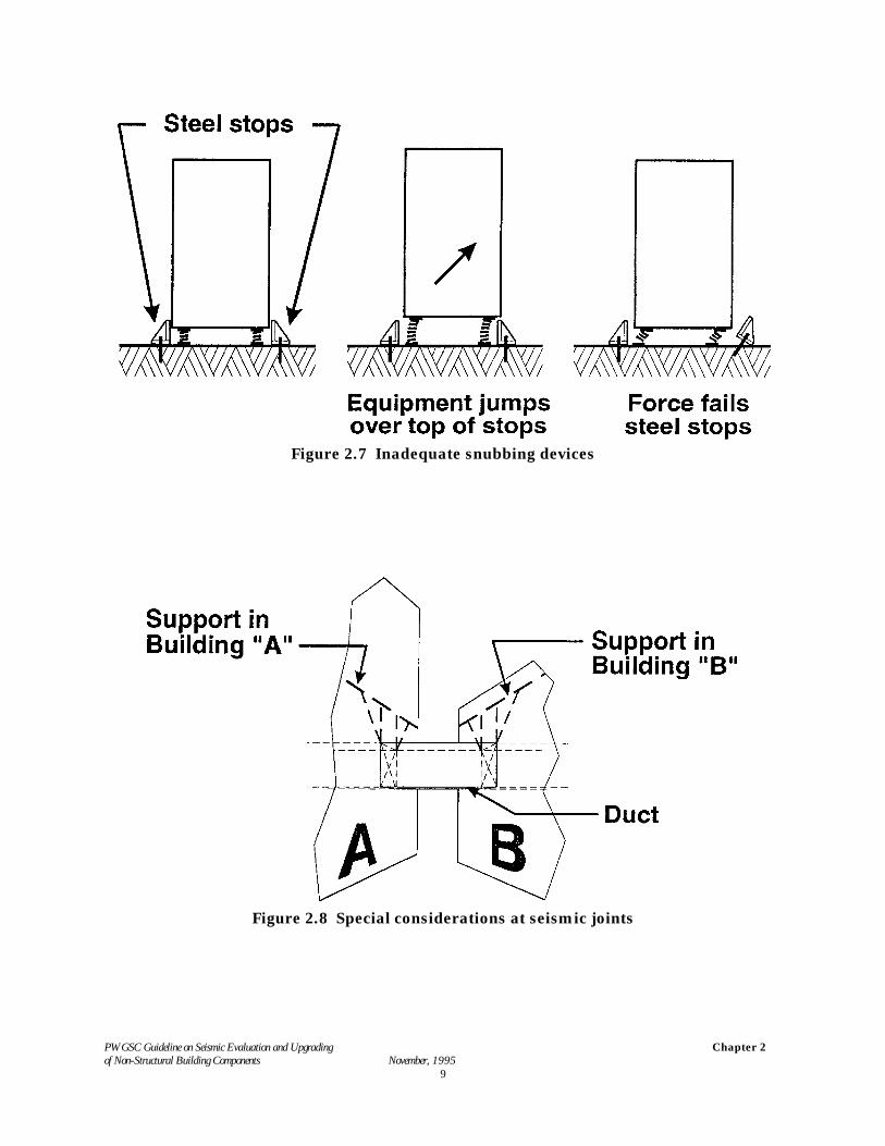
Spring isolated equipment presents a special set of problems for seismic restraint. It is important to avoidcompromising the effectiveness of the vibration isolators when designing seismic restraints for this type ofcomponent installation. Two failure modes are shown in Figure 2.7. In one case the equipment can fail bybouncing over the top of the stops and in the other case failure occurs through inadequate capacity of theseismic stop connection to the building.
Figure 2.8 shows the case where ducts, pipes or cables span across a seismic joint between buildings or isolatedsections of the same building. When the adjacent structures are of different heights or of different constructiontypes, significant differential movement between the structures can occur. It is important to ensure that theelements which span these joints have sufficient flexibility to accommodate these relative movements.
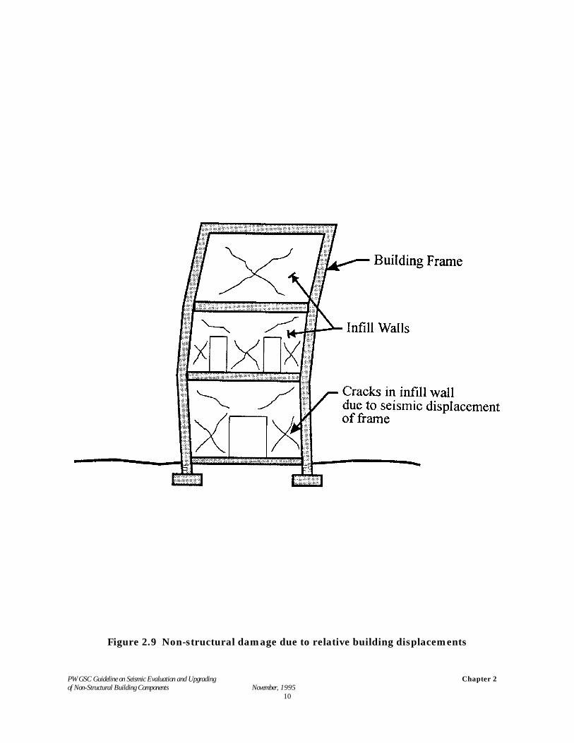
Non-structural components can also be damaged and fail as a result of relative motions of the buildingstructure between floors (Figure 2.9). Where the vertical building structure is relatively flexible between floors(e.g. a moment frame), the structure may impact architectural components such as masonry partitions andcause collapse. Architectural components such as hollow clay tile partitions which are surrounded by astructural frame are much stiffer than the frame and therefore attract large earthquake forces which can resultin sudden collapse. Recommendations for addressing this problem are given in NRC (1995).
The above discussion is based on the horizontal components of earthquake motions. Vertical motions alsooccur at the same time, but vertical motions are generally not a factor in the seismic performance of buildingcomponents.
PWGSC Guideline on Seismic Evaluation and Upgrading of Non-Structural Building Components November, 1995
Chapter 2
7
Figure 2. 3 Proportions of furniture will determine the type of response to E/Q shaking
Figure 2.4 How equipment inside a building fails
PWGSC Guideline on Seismic Evaluation and Upgrading of Non-Structural Building Components November, 1995
Chapter 2
8
Figure 2.5 How equipment inside a building fails
Figure 2.6 Unrestrained suspended equipment
PWGSC Guideline on Seismic Evaluation and Upgrading of Non-Structural Building Components November, 1995
Chapter 2
9
Figure 2.7 Inadequate snubbing devices
Figure 2.8 Special considerations at seismic joints
PWGSC Guideline on Seismic Evaluation and Upgrading of Non-Structural Building Components November, 1995
Chapter 2
10
Figure 2.9 Non-structural damage due to relative building displacements
PWGSC Guideline on Seismic Evaluation and Upgrading of Non-Structural Building Components November, 1995
Chapter 2
11
2.3 Loads and Deflections (from the National Building Code 1995)
2.3.1 Inertial Forces: Non-structural components are subjected to horizontal accelerations duringan earthquake resulting in horizontal inertial forces transferred to the building structure through theconnections. The lateral inertial force, Vp, for the design of component connections is determined from:
Vp = "E @ v @ I @ Sp [2.1]
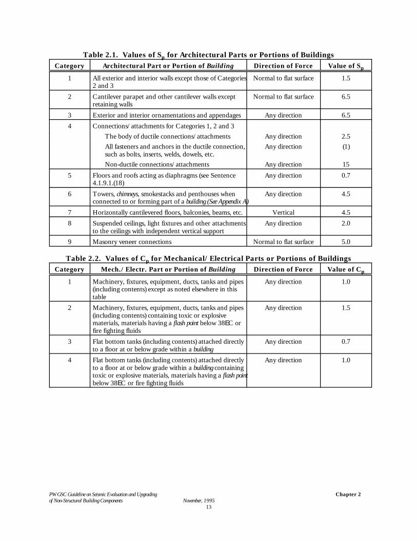
where Sp = horizontal force factor for the component or its anchorage as given in Table 2.1for architectural components and Equation [2.2] for mechanical/electricalcomponents.
I = seismic importance factor for the building, equal to 1.0 for buildings within thescope of this document
v = NBC zonal velocity ratio specified for the location
"E = a load factor equal to 0.6 to trigger upgrading for existing non-structuralbuilding components (NRC, 1993-1), 1.0 for the design of upgrading for existingor new non-structural building components.
For mechanical/electrical components the value of Sp in Equation [2.1] is determined fromSp = Cp @ Ar @ Ax [2.2]
where Ax = 1.0 + hx/hn (hn is the height of the building above its base, and hx is the heightof the component above the base of the building)
Ar = 1.0 for components that are both rigid and rigidly-connected and for non-brittlepipes and ducts
= 1.5 for components located on the ground that are flexible or flexibly-connectedexcept for non-brittle pipes and ducts
= 3.0 for all other casesCp = seismic coefficient for components of mechanical/electrical equipment as given
in Table 2.2
Mechanical/electrical components that are both rigid and rigidly-connected are defined as those having afundamental period for the component and connection less than or equal to 0.06 seconds and flexiblecomponents as those having a fundamental period greater than 0.06 seconds. A background to these criteria iscontained in Commentary J to Part 4 of the NBC.
2.3.2 Deflections of the Building Structures. Lateral deflections of the building structure areestimated from an elastic analysis of the structure under seismic loads determined in accordance with the NBCbut with R taken equal to 1.0. For buildings within the scope of this document the NBC limits interstoreydeflections to 0.02 hs, where hs is the interstorey height. (See also NRCC 1993-1 for criteria for existingbuildings)
For evaluation of existing buildings, the interstorey deflection may need to be estimated and compared withgaps between structural and non-structural components for likely impacts. Non-structural componentscrossing movement joints (Figure 2.8) can be subjected to differential movements resulting from the sum of the
PWGSC Guideline on Seismic Evaluation and Upgrading of Non-Structural Building Components November, 1995
Chapter 2
12
lateral deflections of both building parts.
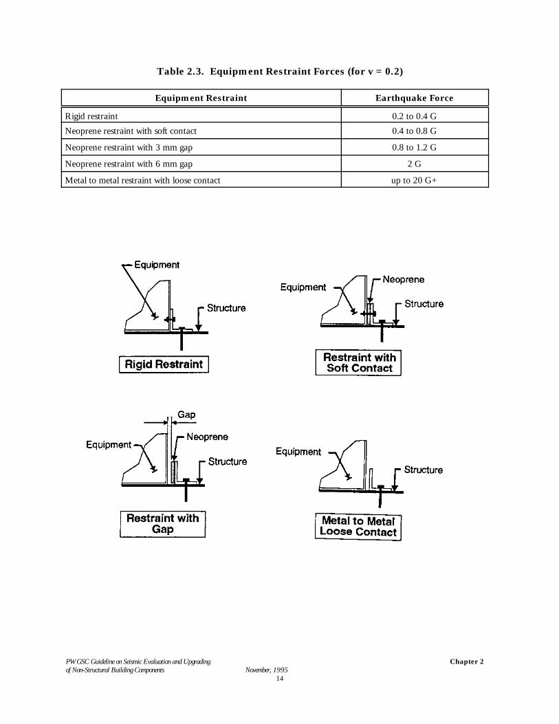
2.4 Equipment Restraint Forces
The type of connection between a component and the structure greatly influences the magnitude of seismicforce. For components connected directly to the structure by bolting or welding the connection forcesdetermined from Section 2.3 are generally low. As the connection flexibility increases the forces that developbecome larger. For equipment resting on flexible isolators (which are used to prevent vibration and soundtransmission), large impact forces can be developed during an earthquake. Typical force levels in connectionsfor systems located in NBCC seismic Zone 4 are shown in Table 2.3.
2.5 Unreinforced Masonry Bearing-Wall Buildings
Recommendations for the evaluation and upgrading of unreinforced masonry bearing-wall buildings,including parapets, partitions and walls which are part of or interact with the structure, are contained inAppendix A of NRC (1993-1)
2.6 Low Seismicity
The National Building Code 1995 does not require seismic design for non-structural building componentswhen either the velocity-related zone, Zv, or the acceleration-related seismic zone, Za, is equal to or less than 1and the foundation factor, F, is less than 1.3. A number of prescriptive criteria are provided in Chapter 5 for typical non-structural systems such as hungceilings; some of these criteria differentiate between low seismicity and medium to high seismicity. Forpurposes of this differentiation, low seismicity is defined when the product v @ F is less than or equal to 0.1,where v is the zonal velocity ratio and F the foundation factor.
PWGSC Guideline on Seismic Evaluation and Upgrading of Non-Structural Building Components November, 1995
Chapter 2
13
Table 2.1. Values of Sp for Architectural Parts or Portions of BuildingsCategory Architectural Part or Portion of Building Direction of Force Value of Sp
1 All exterior and interior walls except those of Categories2 and 3
Normal to flat surface 1.5
2 Cantilever parapet and other cantilever walls exceptretaining walls
Normal to flat surface 6.5
3 Exterior and interior ornamentations and appendages Any direction 6.54 Connections/attachments for Categories 1, 2 and 3
The body of ductile connections/attachments Any direction 2.5All fasteners and anchors in the ductile connection,such as bolts, inserts, welds, dowels, etc.
Any direction (1)
Non-ductile connections/attachments Any direction 155 Floors and roofs acting as diaphragms (see Sentence
4.1.9.1.(18)Any direction 0.7
6 Towers, chimneys, smokestacks and penthouses whenconnected to or forming part of a building (See Appendix A)
Any direction 4.5
7 Horizontally cantilevered floors, balconies, beams, etc. Vertical 4.58 Suspended ceilings, light fixtures and other attachments
to the ceilings with independent vertical supportAny direction 2.0
9 Masonry veneer connections Normal to flat surface 5.0
Table 2.2. Values of Cp for Mechanical/Electrical Parts or Portions of BuildingsCategory Mech./Electr. Part or Portion of Building Direction of Force Value of Cp
1 Machinery, fixtures, equipment, ducts, tanks and pipes(including contents) except as noted elsewhere in thistable
Any direction 1.0
2 Machinery, fixtures, equipment, ducts, tanks and pipes(including contents) containing toxic or explosivematerials, materials having a flash point below 38EC orfire fighting fluids
Any direction 1.5
3 Flat bottom tanks (including contents) attached directlyto a floor at or below grade within a building
Any direction 0.7
4 Flat bottom tanks (including contents) attached directlyto a floor at or below grade within a building containingtoxic or explosive materials, materials having a flash pointbelow 38EC or fire fighting fluids
Any direction 1.0
PWGSC Guideline on Seismic Evaluation and Upgrading of Non-Structural Building Components November, 1995
Chapter 2
14
Table 2.3. Equipment Restraint Forces (for v = 0.2)
Equipment Restraint Earthquake Force
Rigid restraint 0.2 to 0.4 GNeoprene restraint with soft contact 0.4 to 0.8 G
Neoprene restraint with 3 mm gap 0.8 to 1.2 G
Neoprene restraint with 6 mm gap 2 G
Metal to metal restraint with loose contact up to 20 G+
PWGSC Guideline on Seismic Evaluation and Upgrading of Non-Structural Building Components November, 1995
Chapter 3
15
3. MITIGATION PRINCIPLES
3.1 Main Approaches to Mitigation of Seismic Risk
To mitigate the risk of failure of architectural components and equipment due to the relativedisplacements between the structure and the components two options are available: (1) to modifythe component and/or its connections to accommodate the seismic movement of the building; (2)to stiffen the building in order to reduce the seismic displacements and thus prevent componentdamage.
3.2 Techniques of Component Upgrading
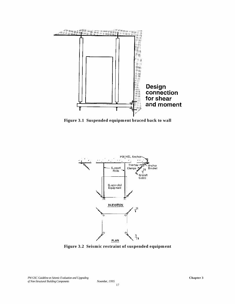
The failure of non-structural components in seismic events can often be prevented by provision ofadequate restraints. Restraints can be in the form of connections or bracing between the componentand the structure or of movement-limiting devices to control the relative movements between thecomponents and the structure. See Figures 3.1 and 3.2. The bracing and connections requireadequate strength to resist the design forces and also need to be sufficiently flexible to accommodaterelative seismic displacements. Care is required to avoid high impact forces in connections. Inparticular steel to steel impacts are unacceptable during seismic response because of the large impactforces that can be generated (see Section 2.4).
It is sometimes possible to increase stability by bolting together adjacent racks or cabinets.
In some cases seismic risk can be mitigated by the removal of components such as heavy roofparapets or disused mechanical or electrical components or by moving items from a hazardouslocation to a less hazardous location. Where the failure or displacement of a component poses norisk to life safety it may be acceptable to lose or damage the object and replace or repair thecomponent following the earthquake. This alternative requires good judgement and common sense.
3.3 Risk Considerations
The location of components is an important characteristic when considering safety aspects of apotential failure. Higher priorities should be assigned to components in locations where failure ofthe component poses a threat to life or personal injury.
Risk of failure can be considerably reduced by reduction of weight or changing the weightdistribution of an object, as for example in rearranging the contents in a cupboard to locate theheavy objects at the bottom and the lighter ones at the top.
PWGSC Guideline on Seismic Evaluation and Upgrading of Non-Structural Building Components November, 1995
Chapter 3
16
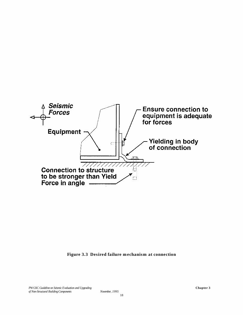
3.4 Behaviour Considerations
The behaviour of a component under seismic motions should be considered in order to ensure thatthe component response will be compatible with the structural response. Connections should bedesigned for a controlled failure mode so that sudden failure of connecting elements is avoided. Anexample is given in Fig. 3.3.
3.5 Other Considerations
For selecting and designing appropriate mitigation techniques it is also important to bear in mindthe cost of the upgrading, and the disruption to the function of the building. Timing of theinstallation should be arranged so that disruption and loss of function of the building are minimized.A reduction in cost and disruption can often be achieved if seismic upgrading of non-structuralbuilding components can be combined with other maintenance or renovation activities.
PWGSC Guideline on Seismic Evaluation and Upgrading of Non-Structural Building Components November, 1995
Chapter 3
17
Figure 3.1 Suspended equipment braced back to wall
Figure 3.2 Seismic restraint of suspended equipment
PWGSC Guideline on Seismic Evaluation and Upgrading of Non-Structural Building Components November, 1995
Chapter 3
18
Figure 3.3 Desired failure mechanism at connection
PWGSC Guideline on Seismic Evaluation and Upgradingof Non-Structural Building Components November, 1995
Chapter 4
19
4. PROCEDURE FOR EVALUATION, UPGRADING DESIGN ANDMITIGATION PLANNING
The evaluation procedure set out in this section for non-structural building components can be usedfor the development of a mitigation plan that incorporates priorities related to selected performanceobjectives. The performance objectives have to be consistent with other planning objectives for thefacility and be within available resources.
The following evaluation procedure is recommended to establish the relative seismic risks posed bythe non-structural components. Absence of bracing or other seismic protection measures does notnecessarily mean that a component identified as a potential life-safety hazard must be upgraded inorder to meet the overall performance objective. Replacement, relocation or removal of the objectmay also be considered as acceptable mitigation measures.
The life-safety hazard for a component is determined from the product of its seismic, vulnerability(probability of failure) and the life-safety consequences (probability of resultant death or injury) iffailure occurs.
The recommended procedure includes the following steps:
1. A preliminary evaluation2. Definition of the performance objectives for the building3. A building walk-down ( interior & exterior) to establish:
C An inventory of non-structural components, including locations andquantities of selected components
C The vulnerability and failure consequences for each component4. Development of a priority list for mitigation5. Component evaluations6. Choice of upgrading techniques7. Preparation of a mitigation plan.
A final mitigation plan, developed in concert with the owner, must also relate costs to availablebudget and possible time constraints. When these factors are considered, the selected performanceobjectives may have to be modified, and the upgrading carried out in a phased program.
4.1 Preliminary Evaluation
If a seismic evaluation of non-structural components has already been performed on the building,a copy of the report should be obtained and its findings evaluated as a preliminary to using the"walk-down" procedures discussed in this section.
If such a seismic evaluation has not been carried out, Appendix A may be used to carry out apreliminary evaluation. Appendix A contains a checklist of "evaluation statements" reproduced fromNRC (1993-1). Some "evaluation statements" contain criteria which require calculations, thesestatements should be marked as "false" pending further investigation later in the procedure.
PWGSC Guideline on Seismic Evaluation and Upgradingof Non-Structural Building Components November, 1995
Chapter 4
20
4.2 Performance Objectives for the Upgrading
Generally, the performance objective for the upgrading will be life safety as defined Chapters 1 and2. The owner may wish to specify more stringent performance objectives such as damage controlfor special components of the building or to provide short-term performance objectives consistentwithin a general mitigation plan for the facility.
4.3 Building Walk-Down: Inventory, Risk Assessment
In order to assess the extent of the risk associated with seismic failure of non-structural componentsin an existing building, a detailed inventory assessment is necessary. This ensures that all items areaccounted for, and that a reasonably standardized procedure is followed that will result in a balancedassessment of risk, cost, and priority.
One effective assessment procedure is the seismic survey or "walk-down" inspection. The non-structural seismic "walk-down" has two main objectives:
1. To provide an inventory of the non-structural items (architectural, mechanical and electricalcomponents as well as building contents) that are considered important, and to establish theirlocation and quantity.
2. To establish for each component, item, or system, its seismic vulnerability and theconsequences of failure in relation to the performance objectives for upgrading.
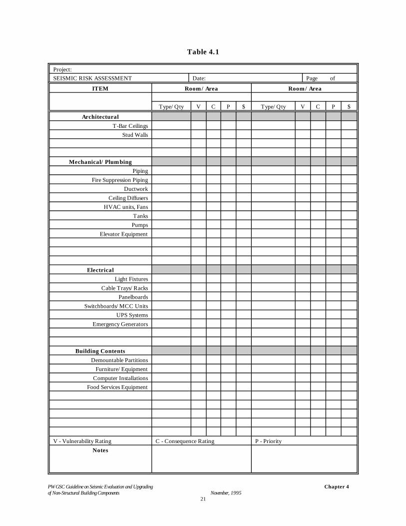
Table 4.1 is an example inventory form. Using Table 1.1 as a basis, Table 4.1 lists items that areexpected in the buildings to be evaluated. Blank spaces are provided in Table 4.1 for special itemsnot listed. The exterior of the building will probably require a separate form. Not all data need becollected in every instance. For lesser upgrading objectives or in situations where upgrading does notdepend on particular information, such as quantity, only sample data are necessary.
PWGSC Guideline on Seismic Evaluation and Upgradingof Non-Structural Building Components November, 1995
Chapter 4
21
Table 4.1
Project:SEISMIC RISK ASSESSMENT Date: Page of
ITEM Room/Area Room/Area
Type/Qty V C P $ Type/Qty V C P $
ArchitecturalT-Bar Ceilings
Stud Walls
Mechanical/PlumbingPiping
Fire Suppression PipingDuctwork
Ceiling DiffusersHVAC units, Fans
TanksPumps
Elevator Equipment
ElectricalLight Fixtures
Cable Trays/RacksPanelboards
Switchboards/MCC UnitsUPS Systems
Emergency Generators
Building ContentsDemountable Partitions
Furniture/EquipmentComputer Installations
Food Services Equipment
V - Vulnerability Rating C - Consequence Rating P - PriorityNotes

PWGSC Guideline on Seismic Evaluation and Upgradingof Non-Structural Building Components November, 1995
Chapter 4
22
PWGSC Guideline on Seismic Evaluation and Upgradingof Non-Structural Building Components November, 1995
Chapter 4
23
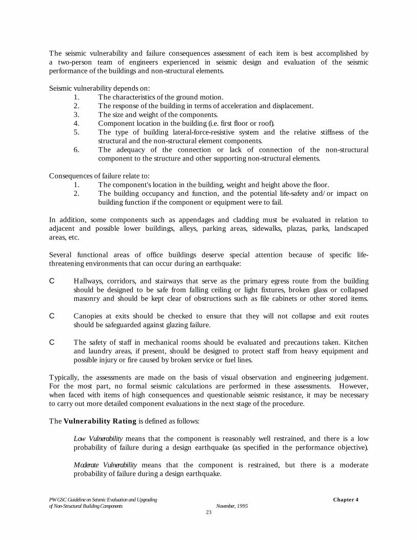
The seismic vulnerability and failure consequences assessment of each item is best accomplished bya two-person team of engineers experienced in seismic design and evaluation of the seismicperformance of the buildings and non-structural elements.
Seismic vulnerability depends on:1. The characteristics of the ground motion.2. The response of the building in terms of acceleration and displacement.3. The size and weight of the components.4. Component location in the building (i.e. first floor or roof).5. The type of building lateral-force-resistive system and the relative stiffness of the
structural and the non-structural element components.6. The adequacy of the connection or lack of connection of the non-structural
component to the structure and other supporting non-structural elements.
Consequences of failure relate to:1. The component's location in the building, weight and height above the floor.2. The building occupancy and function, and the potential life-safety and/or impact on
building function if the component or equipment were to fail.
In addition, some components such as appendages and cladding must be evaluated in relation toadjacent and possible lower buildings, alleys, parking areas, sidewalks, plazas, parks, landscapedareas, etc.
Several functional areas of office buildings deserve special attention because of specific life-threatening environments that can occur during an earthquake:
C Hallways, corridors, and stairways that serve as the primary egress route from the buildingshould be designed to be safe from falling ceiling or light fixtures, broken glass or collapsedmasonry and should be kept clear of obstructions such as file cabinets or other stored items.
C Canopies at exits should be checked to ensure that they will not collapse and exit routesshould be safeguarded against glazing failure.
C The safety of staff in mechanical rooms should be evaluated and precautions taken. Kitchenand laundry areas, if present, should be designed to protect staff from heavy equipment andpossible injury or fire caused by broken service or fuel lines.
Typically, the assessments are made on the basis of visual observation and engineering judgement.For the most part, no formal seismic calculations are performed in these assessments. However,when faced with items of high consequences and questionable seismic resistance, it may be necessaryto carry out more detailed component evaluations in the next stage of the procedure.
The Vulnerability Rating is defined as follows:
Low Vulnerability means that the component is reasonably well restrained, and there is a lowprobability of failure during a design earthquake (as specified in the performance objective).
Moderate Vulnerability means that the component is restrained, but there is a moderateprobability of failure during a design earthquake.
PWGSC Guideline on Seismic Evaluation and Upgradingof Non-Structural Building Components November, 1995
Chapter 4
24
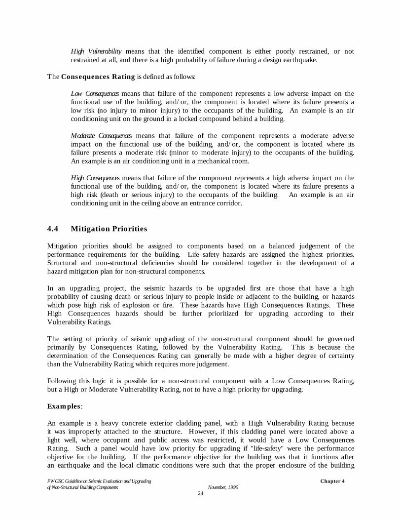
High Vulnerability means that the identified component is either poorly restrained, or notrestrained at all, and there is a high probability of failure during a design earthquake.
The Consequences Rating is defined as follows:
Low Consequences means that failure of the component represents a low adverse impact on thefunctional use of the building, and/or, the component is located where its failure presents alow risk (no injury to minor injury) to the occupants of the building. An example is an airconditioning unit on the ground in a locked compound behind a building.
Moderate Consequences means that failure of the component represents a moderate adverseimpact on the functional use of the building, and/or, the component is located where itsfailure presents a moderate risk (minor to moderate injury) to the occupants of the building.An example is an air conditioning unit in a mechanical room.
High Consequences means that failure of the component represents a high adverse impact on thefunctional use of the building, and/or, the component is located where its failure presents ahigh risk (death or serious injury) to the occupants of the building. An example is an airconditioning unit in the ceiling above an entrance corridor.
4.4 Mitigation Priorities
Mitigation priorities should be assigned to components based on a balanced judgement of theperformance requirements for the building. Life safety hazards are assigned the highest priorities.Structural and non-structural deficiencies should be considered together in the development of ahazard mitigation plan for non-structural components.
In an upgrading project, the seismic hazards to be upgraded first are those that have a highprobability of causing death or serious injury to people inside or adjacent to the building, or hazardswhich pose high risk of explosion or fire. These hazards have High Consequences Ratings. TheseHigh Consequences hazards should be further prioritized for upgrading according to theirVulnerability Ratings.
The setting of priority of seismic upgrading of the non-structural component should be governedprimarily by Consequences Rating, followed by the Vulnerability Rating. This is because thedetermination of the Consequences Rating can generally be made with a higher degree of certaintythan the Vulnerability Rating which requires more judgement.
Following this logic it is possible for a non-structural component with a Low Consequences Rating,but a High or Moderate Vulnerability Rating, not to have a high priority for upgrading.
Examples:
An example is a heavy concrete exterior cladding panel, with a High Vulnerability Rating becauseit was improperly attached to the structure. However, if this cladding panel were located above alight well, where occupant and public access was restricted, it would have a Low ConsequencesRating. Such a panel would have low priority for upgrading if "life-safety" were the performanceobjective for the building. If the performance objective for the building was that it functions afteran earthquake and the local climatic conditions were such that the proper enclosure of the building
PWGSC Guideline on Seismic Evaluation and Upgradingof Non-Structural Building Components November, 1995
Chapter 4
25
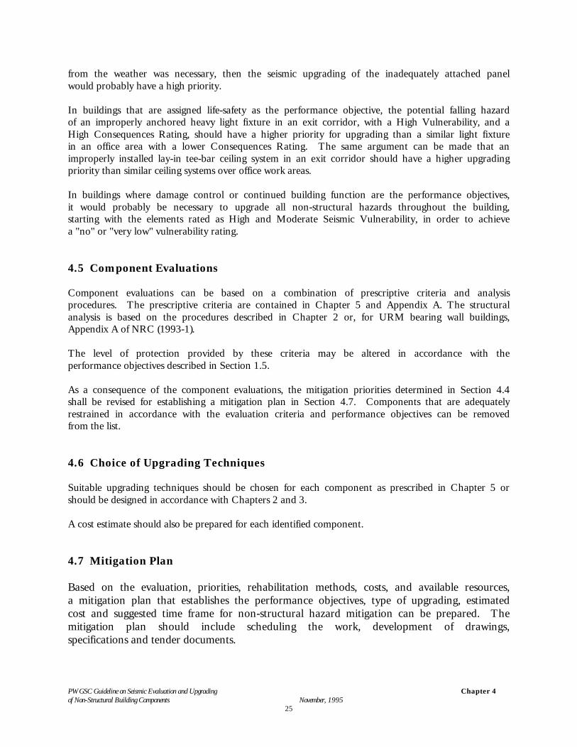
from the weather was necessary, then the seismic upgrading of the inadequately attached panelwould probably have a high priority.
In buildings that are assigned life-safety as the performance objective, the potential falling hazardof an improperly anchored heavy light fixture in an exit corridor, with a High Vulnerability, and aHigh Consequences Rating, should have a higher priority for upgrading than a similar light fixturein an office area with a lower Consequences Rating. The same argument can be made that animproperly installed lay-in tee-bar ceiling system in an exit corridor should have a higher upgradingpriority than similar ceiling systems over office work areas.
In buildings where damage control or continued building function are the performance objectives,it would probably be necessary to upgrade all non-structural hazards throughout the building,starting with the elements rated as High and Moderate Seismic Vulnerability, in order to achievea "no" or "very low" vulnerability rating.
4.5 Component Evaluations
Component evaluations can be based on a combination of prescriptive criteria and analysisprocedures. The prescriptive criteria are contained in Chapter 5 and Appendix A. The structuralanalysis is based on the procedures described in Chapter 2 or, for URM bearing wall buildings,Appendix A of NRC (1993-1).
The level of protection provided by these criteria may be altered in accordance with theperformance objectives described in Section 1.5.
As a consequence of the component evaluations, the mitigation priorities determined in Section 4.4shall be revised for establishing a mitigation plan in Section 4.7. Components that are adequatelyrestrained in accordance with the evaluation criteria and performance objectives can be removedfrom the list.
4.6 Choice of Upgrading Techniques
Suitable upgrading techniques should be chosen for each component as prescribed in Chapter 5 orshould be designed in accordance with Chapters 2 and 3.
A cost estimate should also be prepared for each identified component.
4.7 Mitigation Plan
Based on the evaluation, priorities, rehabilitation methods, costs, and available resources,a mitigation plan that establishes the performance objectives, type of upgrading, estimatedcost and suggested time frame for non-structural hazard mitigation can be prepared. Themitigation plan should include scheduling the work, development of drawings,specifications and tender documents.
PWGSC Guideline on Seismic Evaluation and Upgrading of Non-Structural Building Components November, 1995
Chapter 5
26
5. UPGRADING TECHNIQUES
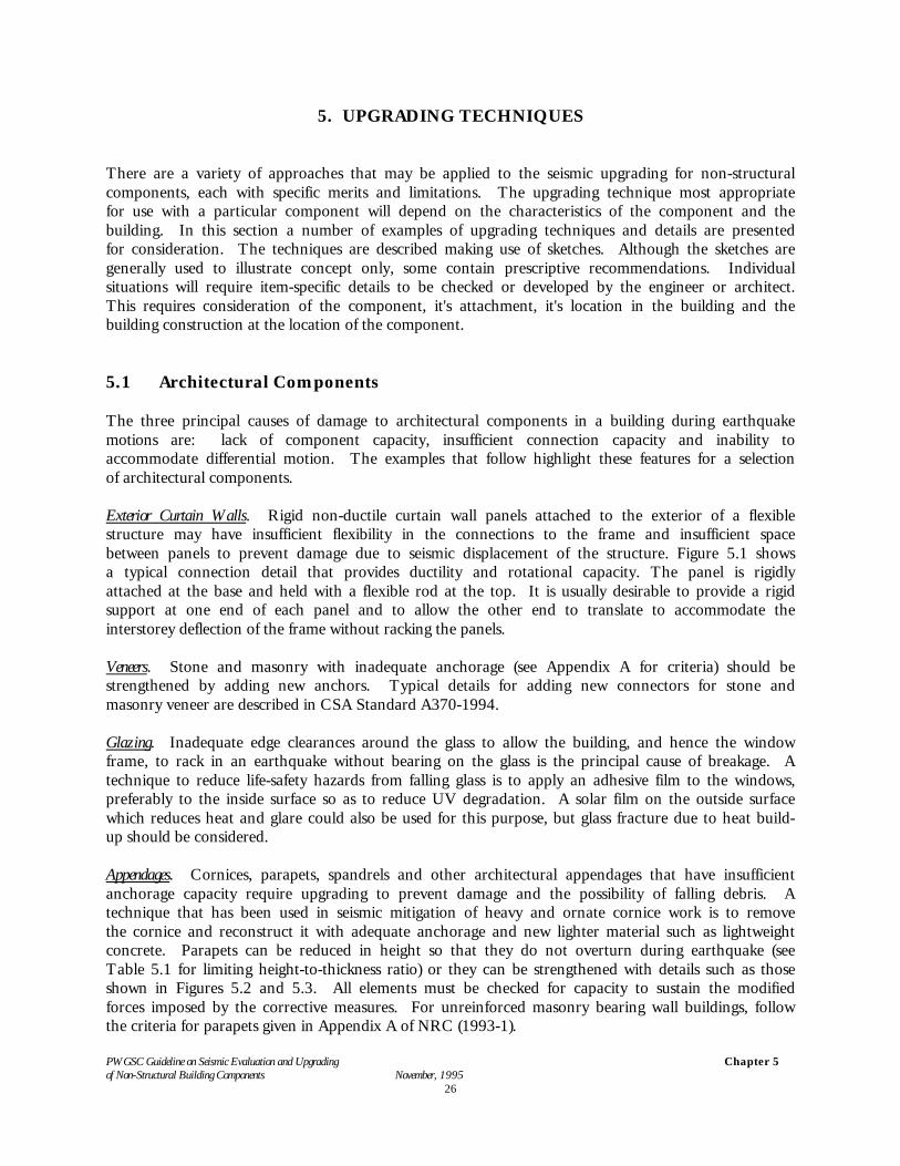
There are a variety of approaches that may be applied to the seismic upgrading for non-structuralcomponents, each with specific merits and limitations. The upgrading technique most appropriatefor use with a particular component will depend on the characteristics of the component and thebuilding. In this section a number of examples of upgrading techniques and details are presentedfor consideration. The techniques are described making use of sketches. Although the sketches aregenerally used to illustrate concept only, some contain prescriptive recommendations. Individualsituations will require item-specific details to be checked or developed by the engineer or architect.This requires consideration of the component, it's attachment, it's location in the building and thebuilding construction at the location of the component.
5.1 Architectural Components
The three principal causes of damage to architectural components in a building during earthquakemotions are: lack of component capacity, insufficient connection capacity and inability toaccommodate differential motion. The examples that follow highlight these features for a selectionof architectural components.
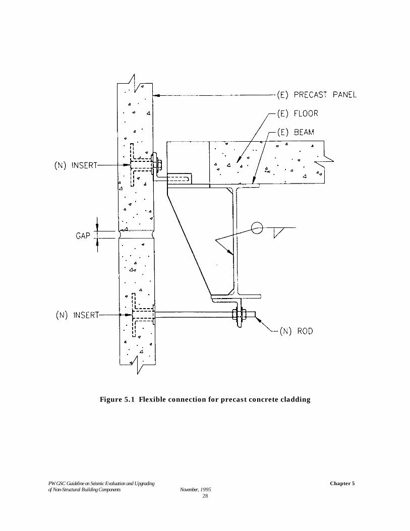
Exterior Curtain Walls. Rigid non-ductile curtain wall panels attached to the exterior of a flexiblestructure may have insufficient flexibility in the connections to the frame and insufficient spacebetween panels to prevent damage due to seismic displacement of the structure. Figure 5.1 showsa typical connection detail that provides ductility and rotational capacity. The panel is rigidlyattached at the base and held with a flexible rod at the top. It is usually desirable to provide a rigidsupport at one end of each panel and to allow the other end to translate to accommodate theinterstorey deflection of the frame without racking the panels.
Veneers. Stone and masonry with inadequate anchorage (see Appendix A for criteria) should bestrengthened by adding new anchors. Typical details for adding new connectors for stone andmasonry veneer are described in CSA Standard A370-1994.
Glazing. Inadequate edge clearances around the glass to allow the building, and hence the windowframe, to rack in an earthquake without bearing on the glass is the principal cause of breakage. Atechnique to reduce life-safety hazards from falling glass is to apply an adhesive film to the windows,preferably to the inside surface so as to reduce UV degradation. A solar film on the outside surfacewhich reduces heat and glare could also be used for this purpose, but glass fracture due to heat build-up should be considered.
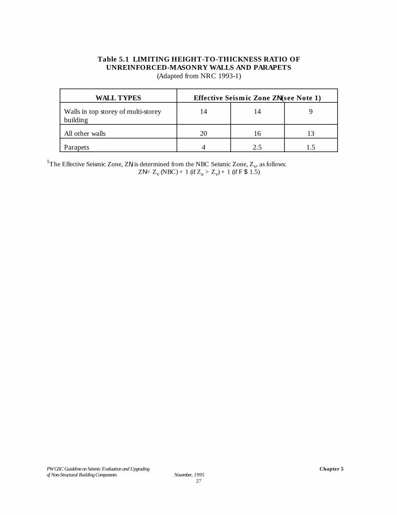
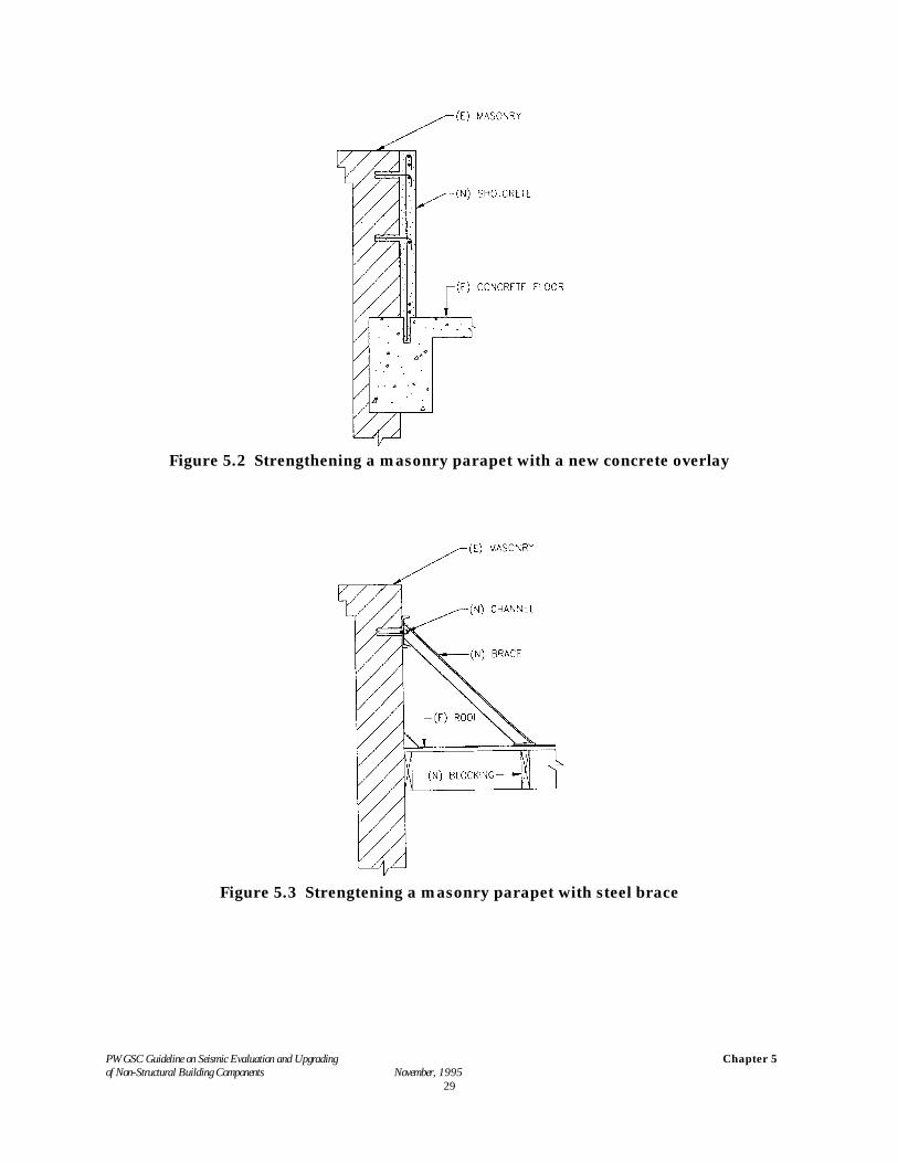
Appendages. Cornices, parapets, spandrels and other architectural appendages that have insufficientanchorage capacity require upgrading to prevent damage and the possibility of falling debris. Atechnique that has been used in seismic mitigation of heavy and ornate cornice work is to removethe cornice and reconstruct it with adequate anchorage and new lighter material such as lightweightconcrete. Parapets can be reduced in height so that they do not overturn during earthquake (seeTable 5.1 for limiting height-to-thickness ratio) or they can be strengthened with details such as thoseshown in Figures 5.2 and 5.3. All elements must be checked for capacity to sustain the modifiedforces imposed by the corrective measures. For unreinforced masonry bearing wall buildings, followthe criteria for parapets given in Appendix A of NRC (1993-1).
PWGSC Guideline on Seismic Evaluation and Upgrading of Non-Structural Building Components November, 1995
Chapter 5
27
Table 5.1 LIMITING HEIGHT-TO-THICKNESS RATIO OFUNREINFORCED-MASONRY WALLS AND PARAPETS
(Adapted from NRC 1993-1)
WALL TYPES Effective Seismic Zone ZN (see Note 1)
Walls in top storey of multi-storeybuilding
14 14 9
All other walls 20 16 13
Parapets 4 2.5 1.5
1The Effective Seismic Zone, ZN, is determined from the NBC Seismic Zone, Zv, as follows:ZN = Zv (NBC) + 1 (if Za > Zv) + 1 (if F $ 1.5)
PWGSC Guideline on Seismic Evaluation and Upgrading of Non-Structural Building Components November, 1995
Chapter 5
28
Figure 5.1 Flexible connection for precast concrete cladding
PWGSC Guideline on Seismic Evaluation and Upgrading of Non-Structural Building Components November, 1995
Chapter 5
29
Figure 5.2 Strengthening a masonry parapet with a new concrete overlay
Figure 5.3 Strengtening a masonry parapet with steel brace
PWGSC Guideline on Seismic Evaluation and Upgrading of Non-Structural Building Components November, 1995
Chapter 5
30
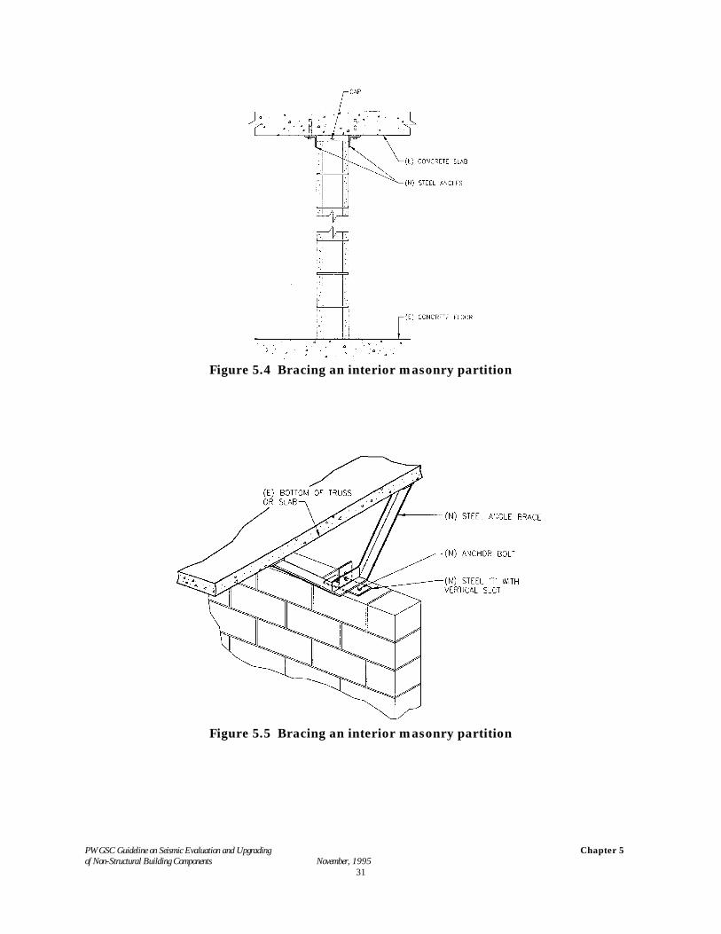
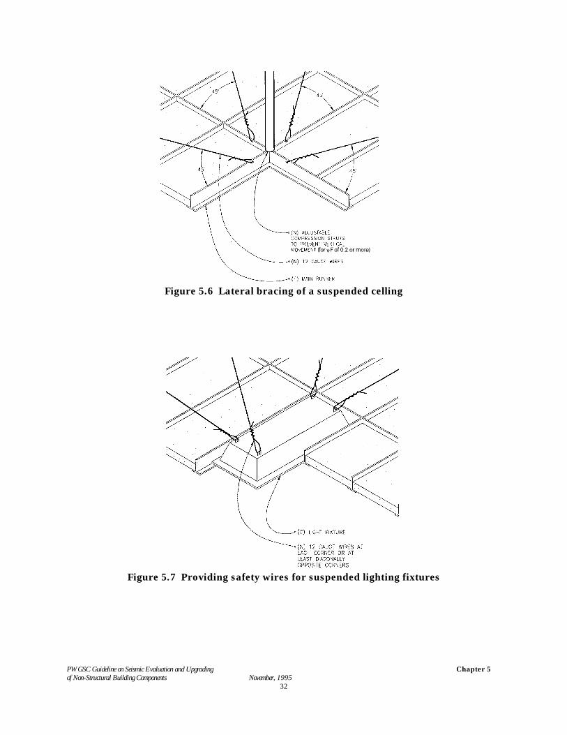
Partitions. Heavy partitions such as those of concrete or clay blocks without adequate lateral stabilityand connection capacity may fail from out-of-plane displacement or in-plane shear stress caused byinterstorey drift. Such partitions should be fitted with connections similar to those shown in Figure5.4 and 5.5 that restrain out-of-plane displacement and allow in-plane displacement. Also height-to-thickness ratio of unreinforced masonry partitions should not exceed the limit in Table 5.1.Alternatively, unreinforced masonry partitions can be removed and replaced with drywall partitions.
Hollow clay tile partitions occur in many existing buildings as corridor walls or as non-structuralenclosures for elevator shafts or stairwells. Hollow clay tile is a very strong but brittle material andis very susceptible to shattering into fragments that could be hazardous to building occupants andobstruct egress. In many cases it is not possible to isolate these partitions from the lateraldisplacements of the structural framing. In such cases it is advisable to consider either removal ofthese partitions and replacement with drywall construction or restraining the potential fragmentswith a wire mesh or FRP/PRC overlays (see NRCC-1995).
For unreinforced masonry bearing-wall buildings, the partitions interact with the structure. For suchcases refer to Appendix A of NRC (1993-1).
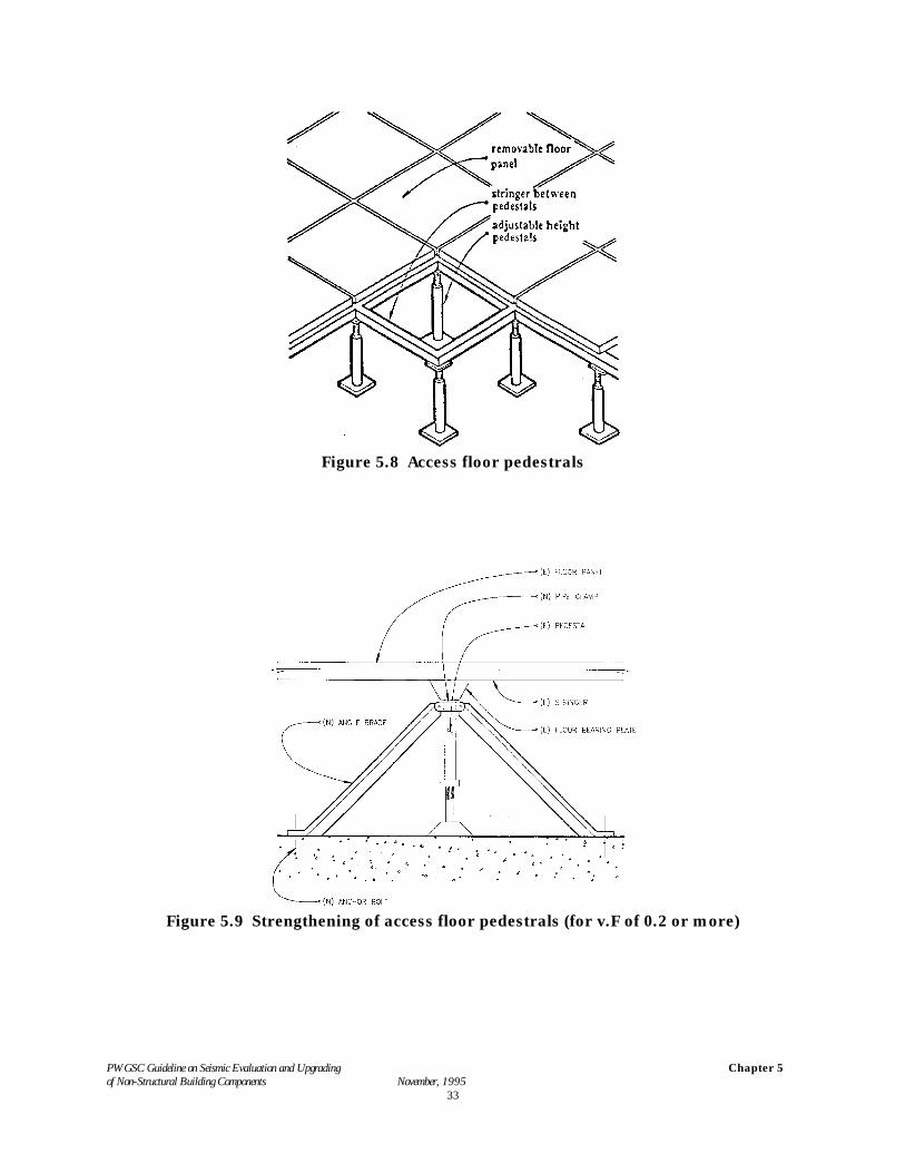
Ceilings. Unbraced suspended ceilings can swing independently of the supporting floor and causedamage to the ceilings, particularly at the perimeters. The provision of four-way (12-gauge wire)diagonals and a compression strut between the ceiling grid and the supporting floor at 3.5 m oncentres and within 1.7 m of partition walls will significantly improve the seismic performance of thesuspended ceiling. Figure 5.6 shows a typical detail of the four-way diagonals and the compressionstrut. In addition to the braces, the connections between the main runners and cross runners shouldbe capable of transferring tension loads. Lay-in ceilings are particularly vulnerable to the relativedisplacements of the supporting grid members. Splices and connections of the T-bar sections thatcomprise the grid may have to be stiffened with new metal clips and self threading screws.
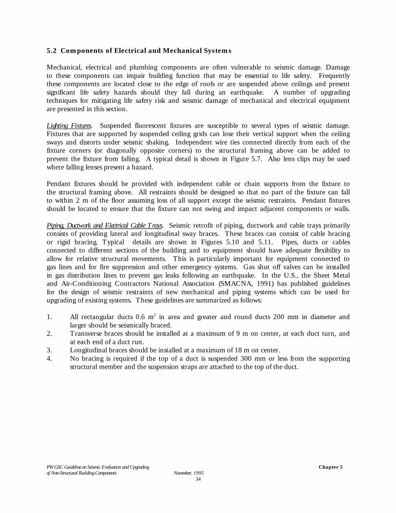
Computer Access Floors. Access floors are typically constructed of square floor panels supported onadjustable column pedestals. The column pedestals are frequently fastened to the floor below withadhesive. Some assemblies have stringers that connect to the tops of the pedestals, see Figure 5.8,and others have the panels connected directly to the pedestals. When subjected to lateral loads,access floors typically are very flexible unless they are specifically designed to be rigid. This flexibilitymay amplify the ground motions such that equipment supported on the floor may experiencesignificantly higher displacements and forces. These higher displacements also may causeconnection failures that could precipitate a collapse of the floor. Existing floors can be upgraded bysecuring the pedestals to the subfloor with concrete anchors or by adding diagonal bracing to thepedestals in a regular pattern. See Figure 5.9. Upgraded floors should be designed and tested tomeet both stiffness and strength criteria.
PWGSC Guideline on Seismic Evaluation and Upgrading of Non-Structural Building Components November, 1995
Chapter 5
31
Figure 5.4 Bracing an interior masonry partition
Figure 5.5 Bracing an interior masonry partition
PWGSC Guideline on Seismic Evaluation and Upgrading of Non-Structural Building Components November, 1995
Chapter 5
32
Figure 5.6 Lateral bracing of a suspended celling
Figure 5.7 Providing safety wires for suspended lighting fixtures
PWGSC Guideline on Seismic Evaluation and Upgrading of Non-Structural Building Components November, 1995
Chapter 5
33
Figure 5.8 Access floor pedestrals
Figure 5.9 Strengthening of access floor pedestrals (for v.F of 0.2 or more)
PWGSC Guideline on Seismic Evaluation and Upgrading of Non-Structural Building Components November, 1995
Chapter 5
34
5.2 Components of Electrical and Mechanical Systems
Mechanical, electrical and plumbing components are often vulnerable to seismic damage. Damageto these components can impair building function that may be essential to life safety. Frequentlythese components are located close to the edge of roofs or are suspended above ceilings and presentsignificant life safety hazards should they fall during an earthquake. A number of upgradingtechniques for mitigating life safety risk and seismic damage of mechanical and electrical equipmentare presented in this section.
Lighting Fixtures. Suspended fluorescent fixtures are susceptible to several types of seismic damage.Fixtures that are supported by suspended ceiling grids can lose their vertical support when the ceilingsways and distorts under seismic shaking. Independent wire ties connected directly from each of thefixture corners (or diagonally opposite corners) to the structural framing above can be added toprevent the fixture from falling. A typical detail is shown in Figure 5.7. Also lens clips may be usedwhere falling lenses present a hazard.
Pendant fixtures should be provided with independent cable or chain supports from the fixture tothe structural framing above. All restraints should be designed so that no part of the fixture can fallto within 2 m of the floor assuming loss of all support except the seismic restraints. Pendant fixturesshould be located to ensure that the fixture can not swing and impact adjacent components or walls.
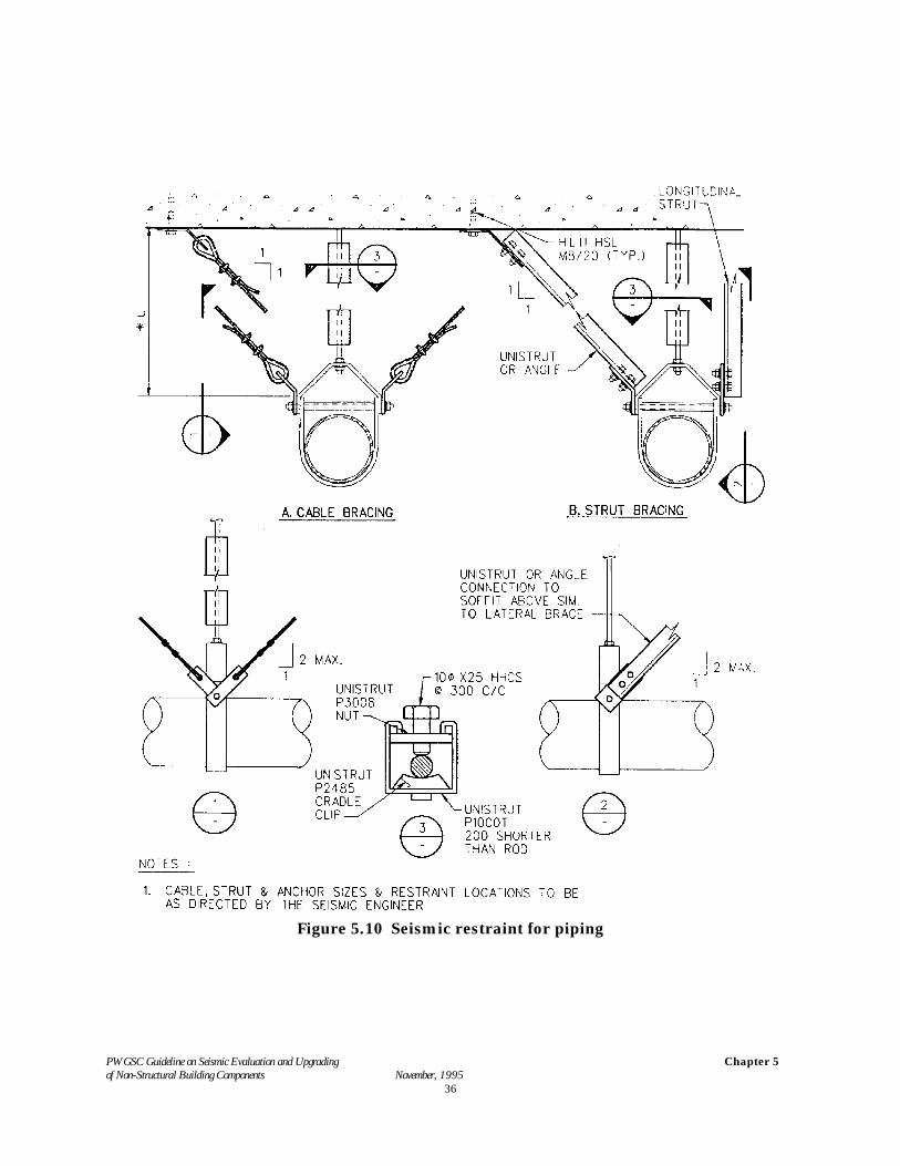
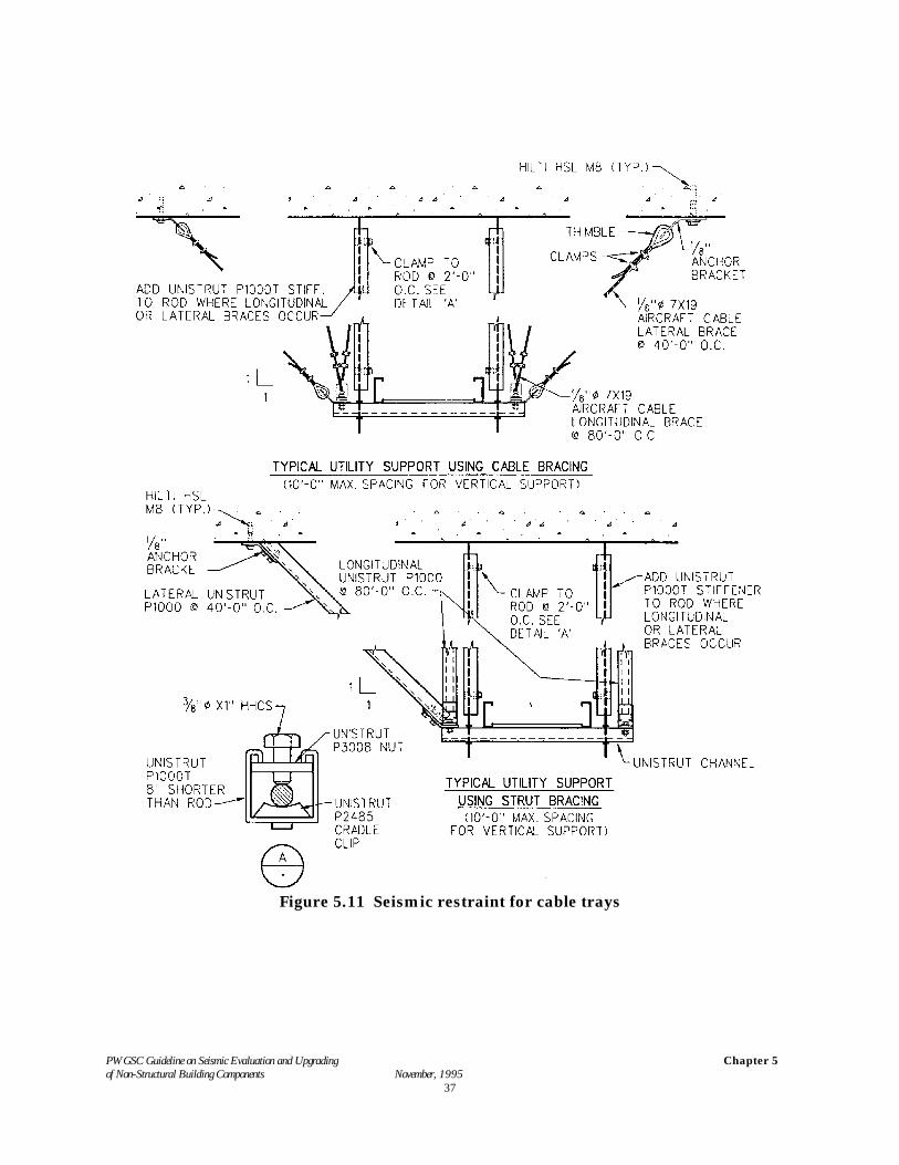
Piping, Ductwork and Electrical Cable Trays. Seismic retrofit of piping, ductwork and cable trays primarilyconsists of providing lateral and longitudinal sway braces. These braces can consist of cable bracingor rigid bracing. Typical details are shown in Figures 5.10 and 5.11. Pipes, ducts or cablesconnected to different sections of the building and to equipment should have adequate flexibility toallow for relative structural movements. This is particularly important for equipment connected togas lines and for fire suppression and other emergency systems. Gas shut off valves can be installedin gas distribution lines to prevent gas leaks following an earthquake. In the U.S., the Sheet Metaland Air-Conditioning Contractors National Association (SMACNA, 1991) has published guidelinesfor the design of seismic restraints of new mechanical and piping systems which can be used forupgrading of existing systems. These guidelines are summarized as follows:
1. All rectangular ducts 0.6 m2 in area and greater and round ducts 200 mm in diameter andlarger should be seismically braced.
2. Transverse braces should be installed at a maximum of 9 m on center, at each duct turn, andat each end of a duct run.
3. Longitudinal braces should be installed at a maximum of 18 m on center.4. No bracing is required if the top of a duct is suspended 300 mm or less from the supporting
structural member and the suspension straps are attached to the top of the duct.
PWGSC Guideline on Seismic Evaluation and Upgrading of Non-Structural Building Components November, 1995
Chapter 5
35
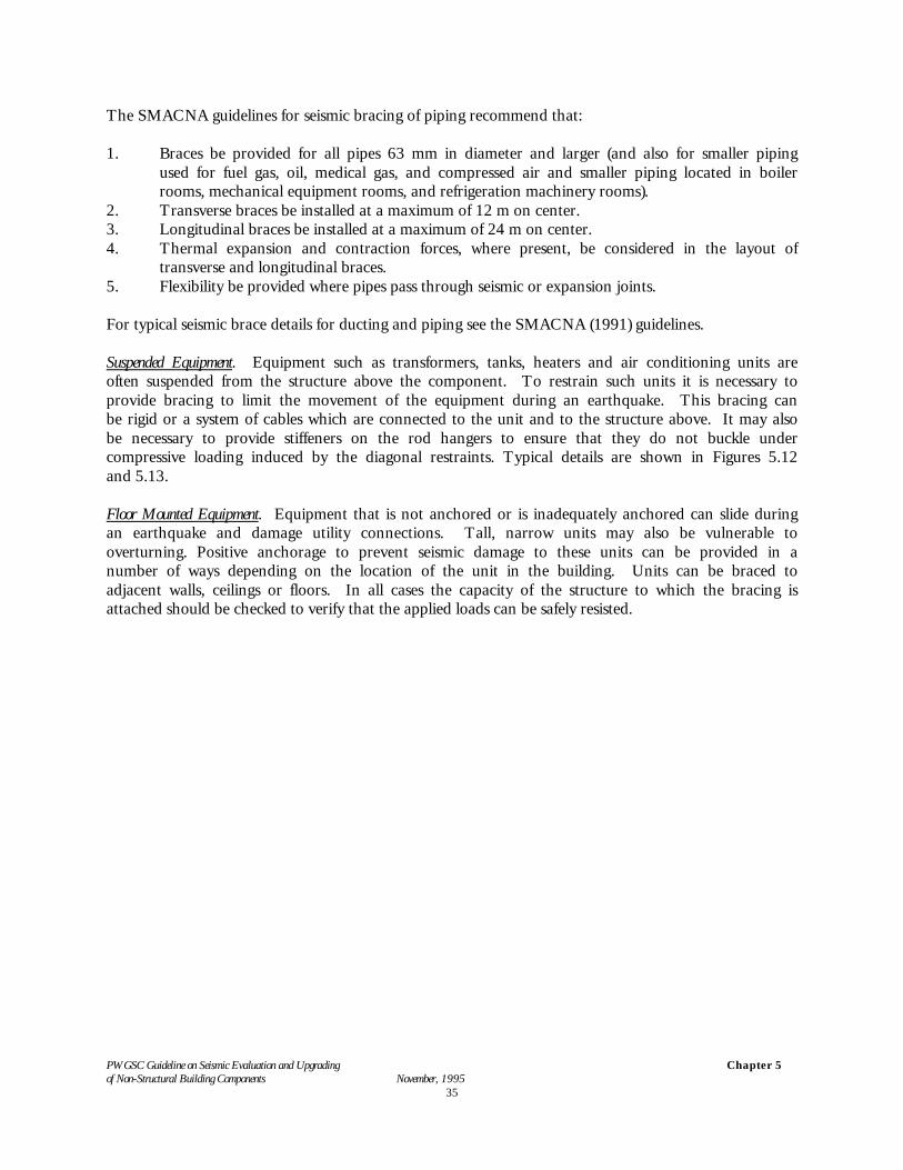
The SMACNA guidelines for seismic bracing of piping recommend that:
1. Braces be provided for all pipes 63 mm in diameter and larger (and also for smaller pipingused for fuel gas, oil, medical gas, and compressed air and smaller piping located in boilerrooms, mechanical equipment rooms, and refrigeration machinery rooms).
2. Transverse braces be installed at a maximum of 12 m on center.3. Longitudinal braces be installed at a maximum of 24 m on center.4. Thermal expansion and contraction forces, where present, be considered in the layout of
transverse and longitudinal braces.5. Flexibility be provided where pipes pass through seismic or expansion joints.
For typical seismic brace details for ducting and piping see the SMACNA (1991) guidelines.
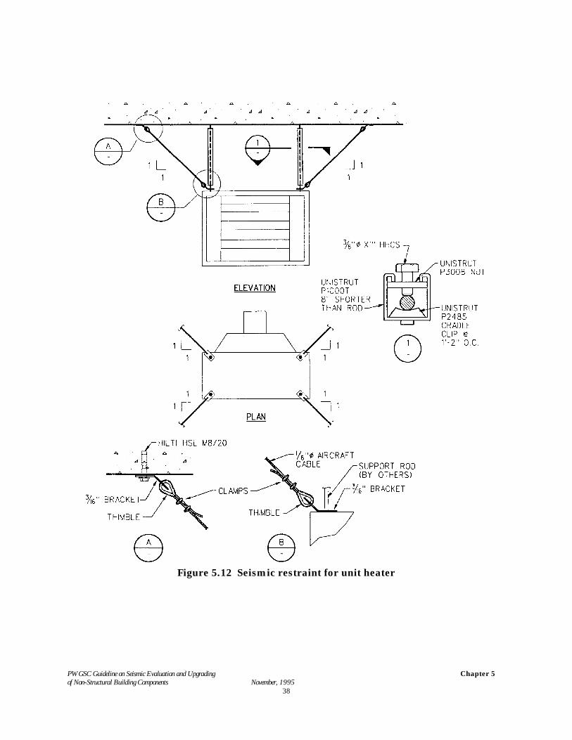
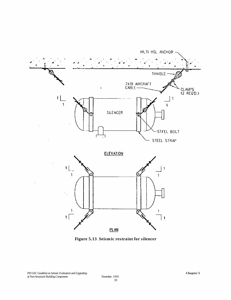
Suspended Equipment. Equipment such as transformers, tanks, heaters and air conditioning units areoften suspended from the structure above the component. To restrain such units it is necessary toprovide bracing to limit the movement of the equipment during an earthquake. This bracing canbe rigid or a system of cables which are connected to the unit and to the structure above. It may alsobe necessary to provide stiffeners on the rod hangers to ensure that they do not buckle undercompressive loading induced by the diagonal restraints. Typical details are shown in Figures 5.12and 5.13.
Floor Mounted Equipment. Equipment that is not anchored or is inadequately anchored can slide duringan earthquake and damage utility connections. Tall, narrow units may also be vulnerable tooverturning. Positive anchorage to prevent seismic damage to these units can be provided in anumber of ways depending on the location of the unit in the building. Units can be braced toadjacent walls, ceilings or floors. In all cases the capacity of the structure to which the bracing isattached should be checked to verify that the applied loads can be safely resisted.
PWGSC Guideline on Seismic Evaluation and Upgrading of Non-Structural Building Components November, 1995
Chapter 5
36
Figure 5.10 Seismic restraint for piping
PWGSC Guideline on Seismic Evaluation and Upgrading of Non-Structural Building Components November, 1995
Chapter 5
37
Figure 5.11 Seismic restraint for cable trays
PWGSC Guideline on Seismic Evaluation and Upgrading of Non-Structural Building Components November, 1995
Chapter 5
38
Figure 5.12 Seismic restraint for unit heater
PWGSC Guideline on Seismic Evaluation and Upgrading of Non-Structural Building Components November, 1995
Chapter 5
39
Figure 5.13 Seismic restraint for silencer
PWGSC Guideline on Seismic Evaluation and Upgrading of Non-Structural Building Components November, 1995
Chapter 5
40
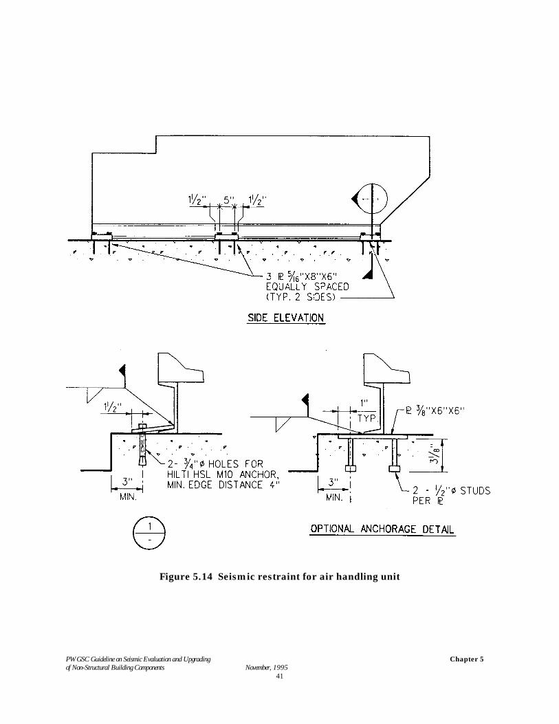
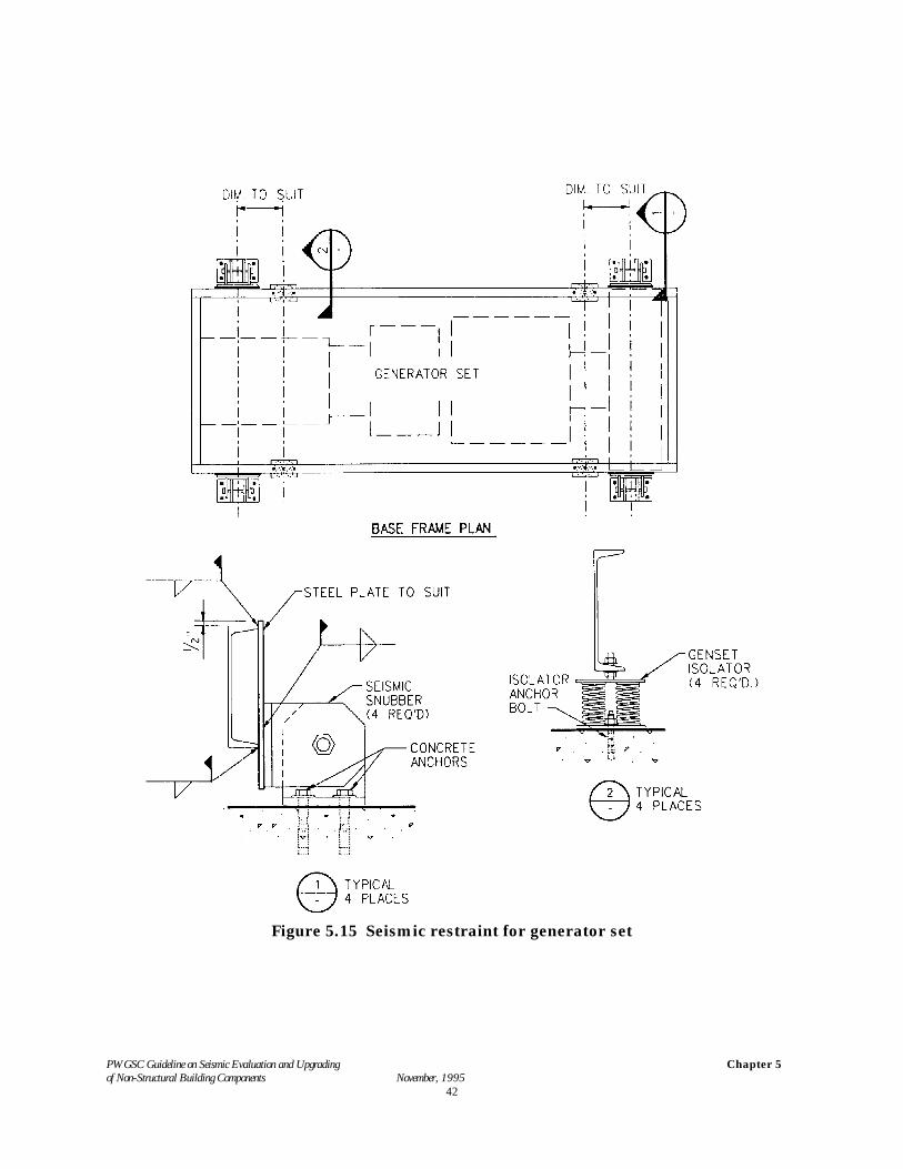
Isolated Equipment. Mechanical or electrical equipment supported on vibration isolators may be particularlyvulnerable to being shaken off the isolator supports during an earthquake. Mitigation of the potential for damageinvolves either replacing the vibration isolation units or installing seismic stops. Vibration isolation units that canalso provide lateral seismic resistance are available from isolator manufactures. These units can be installed inplace of the existing isolators. Alternatively, seismic stops designed to restrict excessive movement of the equipmentcan be installed. A sufficient gap is required between the stop and the equipment to prevent the transmission ofvibrations through the stops. The equipment, the attachment to the isolators or support rails and the railsthemselves can be points of weakness that need to be assessed and strengthened where required. Figures 5.14 and5.15 show typical details for restraining larger floor mounted equipment. See Section 2.4 for estimating restraintforces.
Elevators. The principal hazard in seismic response of elevators is associated with the derailment of counterweights.This is also the most common form of damage in elevator systems subjected to earthquakes. Counterweights thatbecome dislodged from their guide rails often cause damage to the elevator cars with the resulting potential forpersonal injury. To prevent dislodgment of counterweights see the criteria for elevators contained in AppendixA.
Derailment of elevator cars occurs much less frequently during earthquakes and the associated risk to occupantsis small. The usual consequence is loss of operation and delay and inconvenience in freeing occupants from thecars.
Elevator machine room equipment may also require seismic restraint. Electronic seismic cut off switches are ofteninstalled in elevator systems and will require re-setting following an earthquake.
For more information on the requirements for elevator seismic safety see ANSI/ASME A 17.1 - 1984.
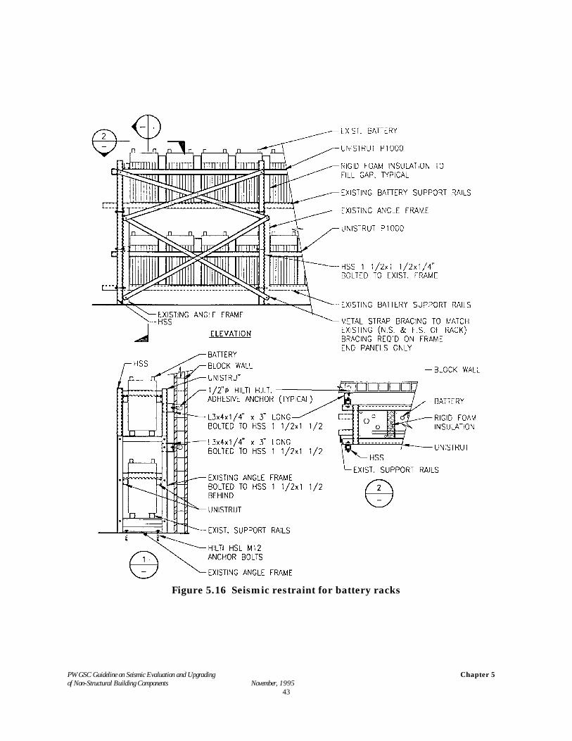
Emergency Power Storage Batteries. Batteries for emergency generators and UPS (Uninterruptible Power Supply)systems require adequate restraint to prevent them from moving and breaking. This is usually accomplished byusing a steel braced frame to hold the batteries in position. The frame has to be adequately anchored to thestructure. Flexibility should be provided in the cables from the batteries to allow for relative movements betweenthe batteries and the structure. See Fig 5.16.
PWGSC Guideline on Seismic Evaluation and Upgrading of Non-Structural Building Components November, 1995
Chapter 5
41
Figure 5.14 Seismic restraint for air handling unit
PWGSC Guideline on Seismic Evaluation and Upgrading of Non-Structural Building Components November, 1995
Chapter 5
42
Figure 5.15 Seismic restraint for generator set
PWGSC Guideline on Seismic Evaluation and Upgrading of Non-Structural Building Components November, 1995
Chapter 5
43
Figure 5.16 Seismic restraint for battery racks
PWGSC Guideline on Seismic Evaluation and Upgrading of Non-Structural Building Components November, 1995
Chapter 5
44
5.3 Building Contents
During an earthquake furniture, moveable equipment and demountable partitions within the interior of thebuilding can slide, overturn or fall. For heavy components this can cause significant life safety risk. Also, thedisplaced components can become obstacles that prevent occupants from exiting the building and this is ofparticular concern in principal exit ways. Components which could create these hazards during an earthquakeshould be restrained. A number of typical details are given in this section which presents several strategies for thesecomponents.
Demountable Partitions. Demountable partitions, which occur in many office occupancies, are usually light and oflow height. Consequently they are generally not a life safety hazard. Demountable partitions which could blockprincipal exit ways should be restrained from overturning or sliding. Also unrestrained demountable partitionsshould not be used to support heavy objects such as computer equipment.
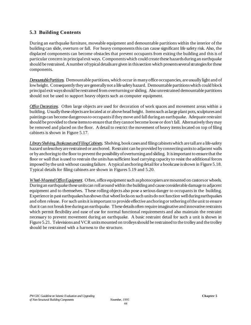
Office Decorations. Often large objects are used for decoration of work spaces and movement areas within abuilding. Usually these objects are located at or above head height. Items such as large plant pots, sculptures andpaintings can become dangerous to occupants if they move and fall during an earthquake. Adequate restraintshould be provided to these items to ensure that they cannot become loose or don't fall. Alternatively they maybe removed and placed on the floor. A detail to restrict the movement of heavy items located on top of filingcabinets is shown in Figure 5.17.
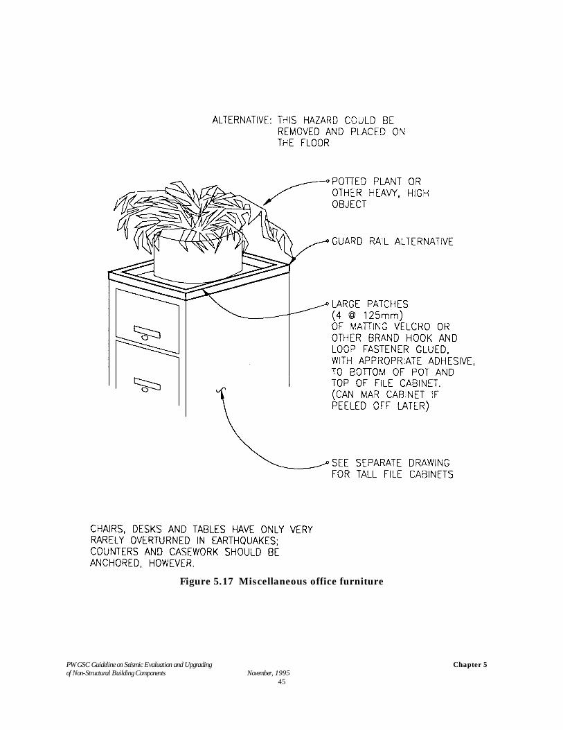
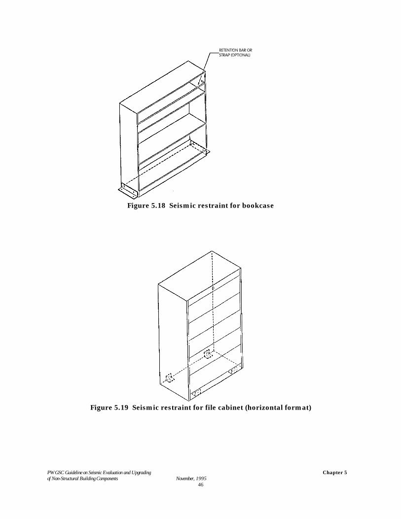
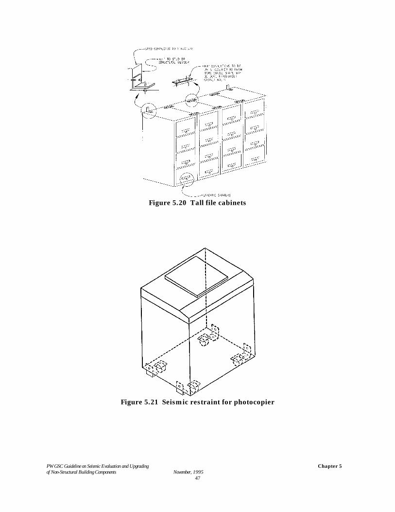
Library Shelving, Bookcases and Filing Cabinets. Shelving, book cases and filing cabinets which are tall are a life-safetyhazard unless they are restrained or anchored. Restraint can be provided by connecting units to adjacent wallsor by anchoring to the floor to prevent the possibility of overturning and sliding. It is important to ensure that thefloor or wall that is used to restrain the units has sufficient load carrying capacity to resist the additional forcesimposed by the unit without causing failure. A typical anchoring detail for a bookcase is shown in Figure 5.18.Typical details for filing cabinets are shown in Figures 5.19 and 5.20.
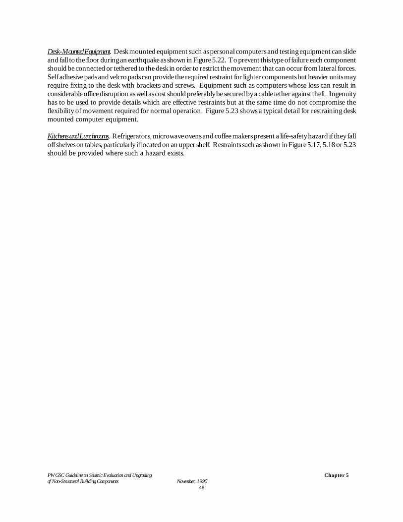
Wheel-Mounted Office Equipment. Often, office equipment such as photocopiers are mounted on castors or wheels.During an earthquake these units can roll around within the building and cause considerable damage to adjacentequipment and to themselves. These rolling objects also pose a serious danger to occupants in the building.Experience in past earthquakes has shown that wheel locks on such units do not function well during earthquakesand often release. For such units it is important to provide effective anchoring or tethering of the unit to ensurethat it can not break free during an earthquake. These details often require imaginative and innovative restraintswhich permit flexibility and ease of use for normal functional requirements and also maintain the restraintnecessary to prevent movement during an earthquake. A basic restraint detail for such a unit is shown inFigure 5.21. Televisions and VCR units mounted on trolleys should be restrained to the trolley and the trolleyshould be restrained with a harness to the structure.
PWGSC Guideline on Seismic Evaluation and Upgrading of Non-Structural Building Components November, 1995
Chapter 5
45
Figure 5.17 Miscellaneous office furniture
PWGSC Guideline on Seismic Evaluation and Upgrading of Non-Structural Building Components November, 1995
Chapter 5
46
Figure 5.18 Seismic restraint for bookcase
Figure 5.19 Seismic restraint for file cabinet (horizontal format)
PWGSC Guideline on Seismic Evaluation and Upgrading of Non-Structural Building Components November, 1995
Chapter 5
47
Figure 5.20 Tall file cabinets
Figure 5.21 Seismic restraint for photocopier
PWGSC Guideline on Seismic Evaluation and Upgrading of Non-Structural Building Components November, 1995
Chapter 5
48
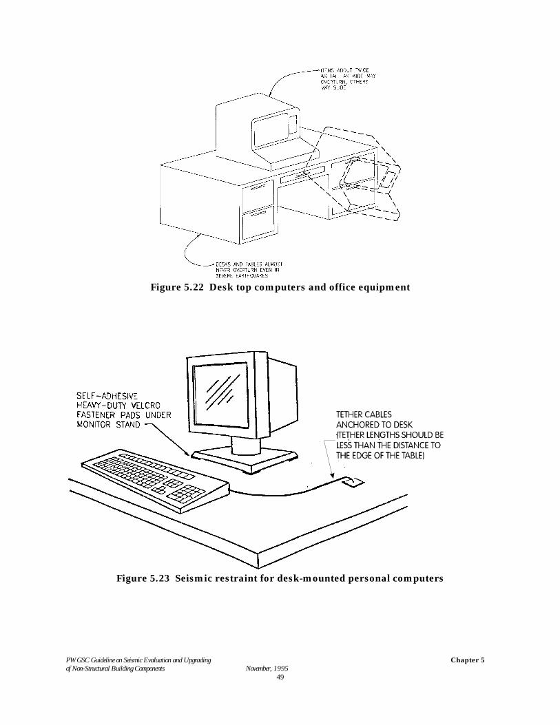
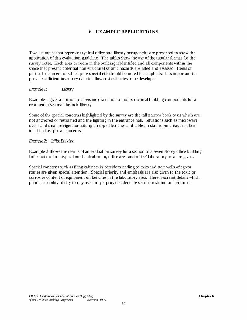
Desk-Mounted Equipment. Desk mounted equipment such as personal computers and testing equipment can slideand fall to the floor during an earthquake as shown in Figure 5.22. To prevent this type of failure each componentshould be connected or tethered to the desk in order to restrict the movement that can occur from lateral forces.Self adhesive pads and velcro pads can provide the required restraint for lighter components but heavier units mayrequire fixing to the desk with brackets and screws. Equipment such as computers whose loss can result inconsiderable office disruption as well as cost should preferably be secured by a cable tether against theft. Ingenuityhas to be used to provide details which are effective restraints but at the same time do not compromise theflexibility of movement required for normal operation. Figure 5.23 shows a typical detail for restraining deskmounted computer equipment.
Kitchens and Lunchrooms. Refrigerators, microwave ovens and coffee makers present a life-safety hazard if they falloff shelves on tables, particularly if located on an upper shelf. Restraints such as shown in Figure 5.17, 5.18 or 5.23should be provided where such a hazard exists.
PWGSC Guideline on Seismic Evaluation and Upgrading of Non-Structural Building Components November, 1995
Chapter 5
49
Figure 5.22 Desk top computers and office equipment
Figure 5.23 Seismic restraint for desk-mounted personal computers
PWGSC Guideline on Seismic Evaluation and Upgrading of Non-Structural Building Components November, 1995
Chapter 6
50
6. EXAMPLE APPLICATIONS
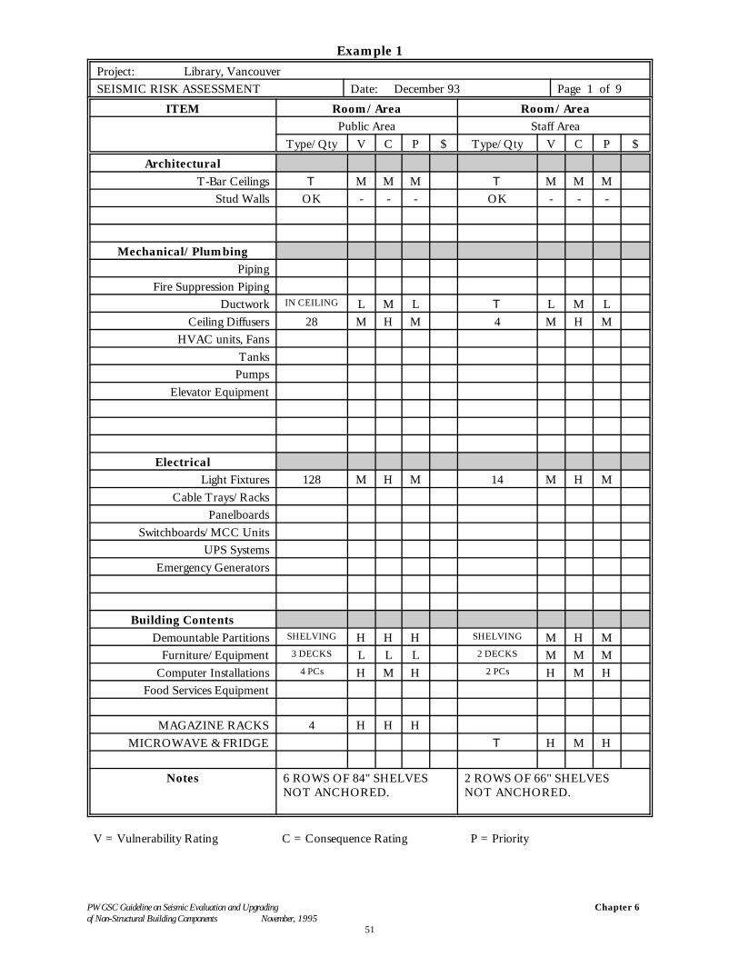
Two examples that represent typical office and library occupancies are presented to show theapplication of this evaluation guideline. The tables show the use of the tabular format for thesurvey notes. Each area or room in the building is identified and all components within thespace that present potential non-structural seismic hazards are listed and assessed. Items ofparticular concern or which pose special risk should be noted for emphasis. It is important toprovide sufficient inventory data to allow cost estimates to be developed.
Example 1: Library
Example 1 gives a portion of a seismic evaluation of non-structural building components for arepresentative small branch library.
Some of the special concerns highlighted by the survey are the tall narrow book cases which arenot anchored or restrained and the lighting in the entrance hall. Situations such as microwaveovens and small refrigerators sitting on top of benches and tables in staff room areas are oftenidentified as special concerns.
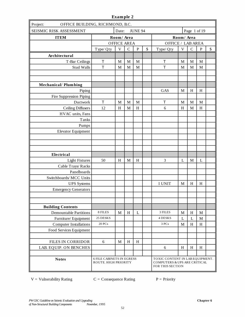
Example 2: Office Building
Example 2 shows the results of an evaluation survey for a section of a seven storey office building. Information for a typical mechanical room, office area and office/laboratory area are given.
Special concerns such as filing cabinets in corridors leading to exits and stair wells of egressroutes are given special attention. Special priority and emphasis are also given to the toxic orcorrosive content of equipment on benches in the laboratory area. Here, restraint details whichpermit flexibility of day-to-day use and yet provide adequate seismic restraint are required.
PWGSC Guideline on Seismic Evaluation and Upgrading of Non-Structural Building Components November, 1995
Chapter 6
51
Example 1Project: Library, VancouverSEISMIC RISK ASSESSMENT Date: December 93 Page 1 of 9
ITEM Room/Area Room/AreaPublic Area Staff Area
Type/Qty V C P $ Type/Qty V C P $Architectural
T-Bar Ceilings T M M M T M M MStud Walls OK - - - OK - - -
Mechanical/PlumbingPiping
Fire Suppression PipingDuctwork IN CEILING L M L T L M L
Ceiling Diffusers 28 M H M 4 M H MHVAC units, Fans
TanksPumps
Elevator Equipment
ElectricalLight Fixtures 128 M H M 14 M H M
Cable Trays/RacksPanelboards
Switchboards/MCC UnitsUPS Systems
Emergency Generators
Building ContentsDemountable Partitions SHELVING H H H SHELVING M H M
Furniture/Equipment 3 DECKS L L L 2 DECKS M M MComputer Installations 4 PCs H M H 2 PCs H M H
Food Services Equipment
MAGAZINE RACKS 4 H H HMICROWAVE & FRIDGE T H M H
Notes 6 ROWS OF 84" SHELVESNOT ANCHORED.
2 ROWS OF 66" SHELVESNOT ANCHORED.
V = Vulnerability Rating C = Consequence Rating P = Priority
PWGSC Guideline on Seismic Evaluation and Upgrading of Non-Structural Building Components November, 1995
Chapter 6
52
Example 2
Project: OFFICE BUILDING, RICHMOND, B.C.SEISMIC RISK ASSESSMENT Date: JUNE 94 Page 1 of 19
ITEM Room/Area Room/AreaOFFICE AREA OFFICE / LAB AREA
Type/Qty V C P $ Type/Qty V C P $Architectural
T-Bar Ceilings T M M M T M M MStud Walls T M M M T M M M
Mechanical/PlumbingPiping GAS M H H
Fire Suppression PipingDuctwork T M M M T M M M
Ceiling Diffusers 12 H M H 6 H M HHVAC units, Fans
TanksPumps
Elevator Equipment
ElectricalLight Fixtures 50 H M H 3 L M L
Cable Trays/RacksPanelboards
Switchboards/MCC UnitsUPS Systems I UNIT M H H
Emergency Generators
Building ContentsDemountable Partitions 8 FILES M H L 3 FILES M H M
Furniture/Equipment 25 DESKS 4 DESKS L L MComputer Installations 20 PCs 3 PCs M H H
Food Services Equipment
FILES IN CORRIDOR 6 M H HLAB. EQUIP. ON BENCHES 6 H H H
Notes 6 FILE CABINETS IN EGRESSROUTE. HIGH PRIORITY
TOXIC CONTENT IN LAB EQUIPMENT. COMPUTERS & UPS ARE CRITICALFOR THIS SECTION
V = Vulnerability Rating C = Consequence Rating P = Priority
PWGSC Guideline on Seismic Evaluation and Upgrading of Non-Structural Building Components November, 1995
Reference
53
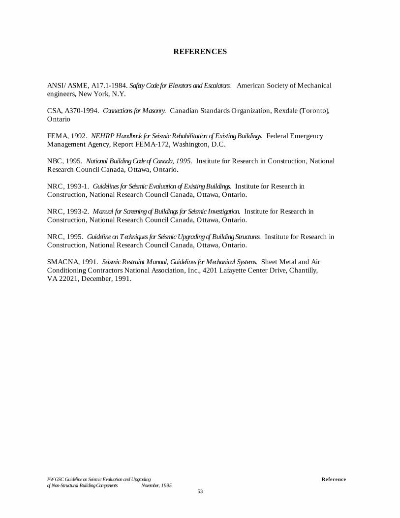
REFERENCES
ANSI/ASME, A17.1-1984. Safety Code for Elevators and Escalators. American Society of Mechanicalengineers, New York, N.Y.
CSA, A370-1994. Connections for Masonry. Canadian Standards Organization, Rexdale (Toronto),Ontario
FEMA, 1992. NEHRP Handbook for Seismic Rehabilitation of Existing Buildings. Federal EmergencyManagement Agency, Report FEMA-172, Washington, D.C.
NBC, 1995. National Building Code of Canada, 1995. Institute for Research in Construction, NationalResearch Council Canada, Ottawa, Ontario.
NRC, 1993-1. Guidelines for Seismic Evaluation of Existing Buildings. Institute for Research inConstruction, National Research Council Canada, Ottawa, Ontario.
NRC, 1993-2. Manual for Screening of Buildings for Seismic Investigation. Institute for Research inConstruction, National Research Council Canada, Ottawa, Ontario.
NRC, 1995. Guideline on Techniques for Seismic Upgrading of Building Structures. Institute for Research inConstruction, National Research Council Canada, Ottawa, Ontario.
SMACNA, 1991. Seismic Restraint Manual, Guidelines for Mechanical Systems. Sheet Metal and AirConditioning Contractors National Association, Inc., 4201 Lafayette Center Drive, Chantilly,VA 22021, December, 1991.
PWGSC Guideline on Seismic Evaluation and Upgrading of Non-Structural Building Components November, 1995
Appendix A
54
APPENDIX A. PRELIMINARY EVALUATION
To help carry out the preliminary evaluation of non-structural building components, thisAppendix contains the following excerpts from NRC (1993-1).
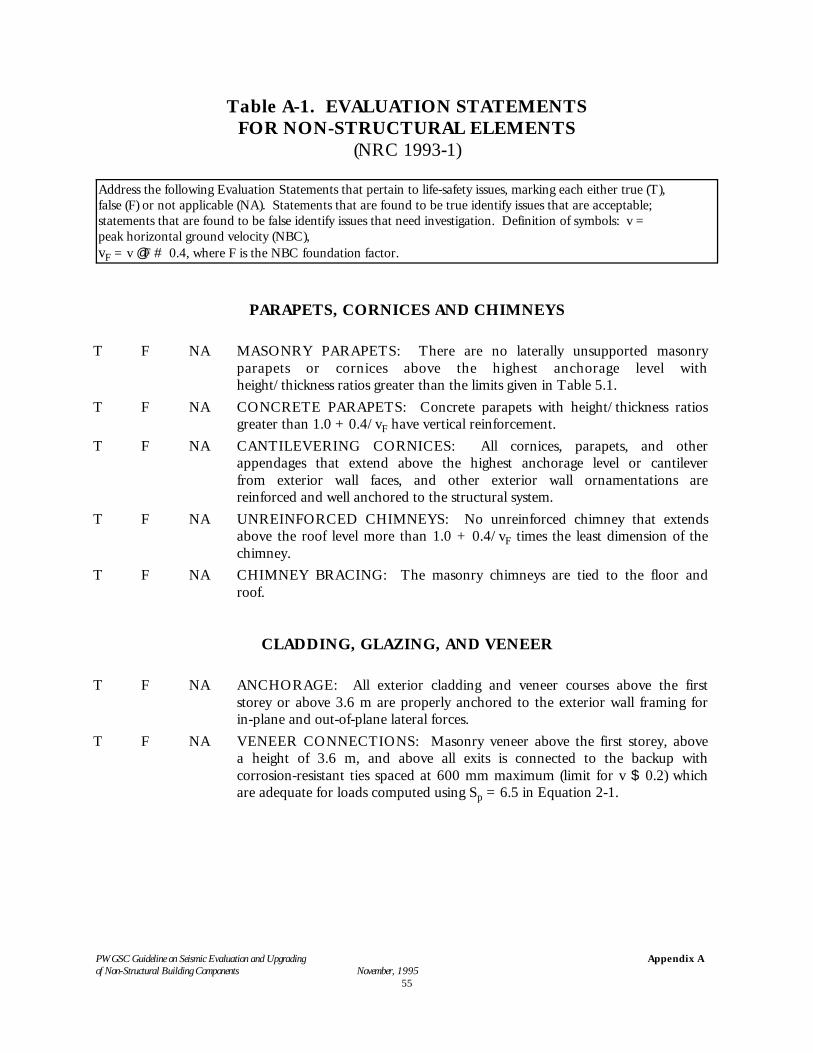
Table A-1 contains a checklist of Evaluation Statements which deal with life-safety concerns. Some of the Evaluation Statements can be answered directly; for the others, including those thatrequire calculations, the component in question should be evaluated later in the procedure inaccordance with step 4 of the procedure contained in Chapter 4.
The preliminary evaluation of non-structural elements require site visits of approximately 1 hourto identify the present status of non-structural items in accordance with the checklist in Table A-1. This site visit is important because these elements might have been modified many timesduring the life of the structure.
PWGSC Guideline on Seismic Evaluation and Upgrading of Non-Structural Building Components November, 1995
Appendix A
55
Table A-1. EVALUATION STATEMENTSFOR NON-STRUCTURAL ELEMENTS
(NRC 1993-1)
Address the following Evaluation Statements that pertain to life-safety issues, marking each either true (T),false (F) or not applicable (NA). Statements that are found to be true identify issues that are acceptable;statements that are found to be false identify issues that need investigation. Definition of symbols: v =peak horizontal ground velocity (NBC), vF = v @ F # 0.4, where F is the NBC foundation factor.
PARAPETS, CORNICES AND CHIMNEYS
T F NA MASONRY PARAPETS: There are no laterally unsupported masonryparapets or cornices above the highest anchorage level withheight/thickness ratios greater than the limits given in Table 5.1.
T F NA CONCRETE PARAPETS: Concrete parapets with height/thickness ratiosgreater than 1.0 + 0.4/vF have vertical reinforcement.
T F NA CANTILEVERING CORNICES: All cornices, parapets, and otherappendages that extend above the highest anchorage level or cantileverfrom exterior wall faces, and other exterior wall ornamentations arereinforced and well anchored to the structural system.
T F NA UNREINFORCED CHIMNEYS: No unreinforced chimney that extendsabove the roof level more than 1.0 + 0.4/vF times the least dimension of thechimney.
T F NA CHIMNEY BRACING: The masonry chimneys are tied to the floor androof.
CLADDING, GLAZING, AND VENEER
T F NA ANCHORAGE: All exterior cladding and veneer courses above the firststorey or above 3.6 m are properly anchored to the exterior wall framing forin-plane and out-of-plane lateral forces.
T F NA VENEER CONNECTIONS: Masonry veneer above the first storey, abovea height of 3.6 m, and above all exits is connected to the backup withcorrosion-resistant ties spaced at 600 mm maximum (limit for v $ 0.2) whichare adequate for loads computed using Sp = 6.5 in Equation 2-1.
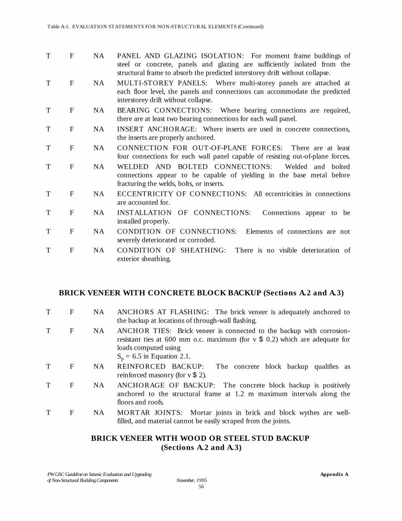
Table A-1. EVALUATION STATEMENTS FOR NON-STRUCTURAL ELEMENTS (Continued)
PWGSC Guideline on Seismic Evaluation and Upgrading of Non-Structural Building Components November, 1995
Appendix A
56
T F NA PANEL AND GLAZING ISOLATION: For moment frame buildings ofsteel or concrete, panels and glazing are sufficiently isolated from thestructural frame to absorb the predicted interstorey drift without collapse.
T F NA MULTI-STOREY PANELS: Where multi-storey panels are attached ateach floor level, the panels and connections can accommodate the predictedinterstorey drift without collapse.
T F NA BEARING CONNECTIONS: Where bearing connections are required,there are at least two bearing connections for each wall panel.
T F NA INSERT ANCHORAGE: Where inserts are used in concrete connections,the inserts are properly anchored.
T F NA CONNECTION FOR OUT-OF-PLANE FORCES: There are at leastfour connections for each wall panel capable of resisting out-of-plane forces.
T F NA WELDED AND BOLTED CONNECTIONS: Welded and boltedconnections appear to be capable of yielding in the base metal beforefracturing the welds, bolts, or inserts.
T F NA ECCENTRICITY OF CONNECTIONS: All eccentricities in connectionsare accounted for.
T F NA INSTALLATION OF CONNECTIONS: Connections appear to beinstalled properly.
T F NA CONDITION OF CONNECTIONS: Elements of connections are notseverely deteriorated or corroded.
T F NA CONDITION OF SHEATHING: There is no visible deterioration ofexterior sheathing.
BRICK VENEER WITH CONCRETE BLOCK BACKUP (Sections A.2 and A.3)
T F NA ANCHORS AT FLASHING: The brick veneer is adequately anchored tothe backup at locations of through-wall flashing.
T F NA ANCHOR TIES: Brick veneer is connected to the backup with corrosion-resistant ties at 600 mm o.c. maximum (for v $ 0.2) which are adequate forloads computed using Sp = 6.5 in Equation 2.1.
T F NA REINFORCED BACKUP: The concrete block backup qualifies asreinforced masonry (for v $ 2).
T F NA ANCHORAGE OF BACKUP: The concrete block backup is positivelyanchored to the structural frame at 1.2 m maximum intervals along thefloors and roofs.
T F NA MORTAR JOINTS: Mortar joints in brick and block wythes are well-filled, and material cannot be easily scraped from the joints.
BRICK VENEER WITH WOOD OR STEEL STUD BACKUP (Sections A.2 and A.3)
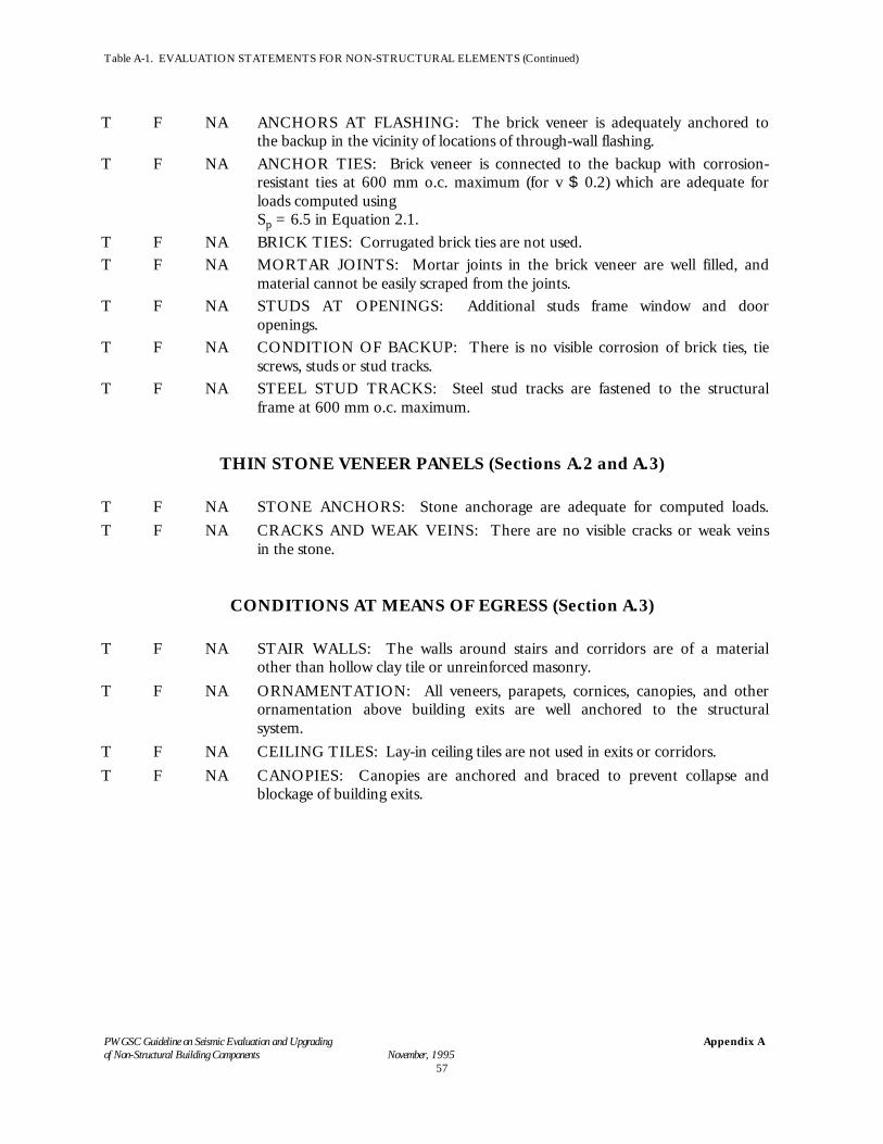
Table A-1. EVALUATION STATEMENTS FOR NON-STRUCTURAL ELEMENTS (Continued)
PWGSC Guideline on Seismic Evaluation and Upgrading of Non-Structural Building Components November, 1995
Appendix A
57
T F NA ANCHORS AT FLASHING: The brick veneer is adequately anchored tothe backup in the vicinity of locations of through-wall flashing.
T F NA ANCHOR TIES: Brick veneer is connected to the backup with corrosion-resistant ties at 600 mm o.c. maximum (for v $ 0.2) which are adequate forloads computed using Sp = 6.5 in Equation 2.1.
T F NA BRICK TIES: Corrugated brick ties are not used.T F NA MORTAR JOINTS: Mortar joints in the brick veneer are well filled, and
material cannot be easily scraped from the joints.T F NA STUDS AT OPENINGS: Additional studs frame window and door
openings.T F NA CONDITION OF BACKUP: There is no visible corrosion of brick ties, tie
screws, studs or stud tracks.T F NA STEEL STUD TRACKS: Steel stud tracks are fastened to the structural
frame at 600 mm o.c. maximum.
THIN STONE VENEER PANELS (Sections A.2 and A.3)
T F NA STONE ANCHORS: Stone anchorage are adequate for computed loads.T F NA CRACKS AND WEAK VEINS: There are no visible cracks or weak veins
in the stone.
CONDITIONS AT MEANS OF EGRESS (Section A.3)
T F NA STAIR WALLS: The walls around stairs and corridors are of a materialother than hollow clay tile or unreinforced masonry.
T F NA ORNAMENTATION: All veneers, parapets, cornices, canopies, and otherornamentation above building exits are well anchored to the structuralsystem.
T F NA CEILING TILES: Lay-in ceiling tiles are not used in exits or corridors.T F NA CANOPIES: Canopies are anchored and braced to prevent collapse and
blockage of building exits.
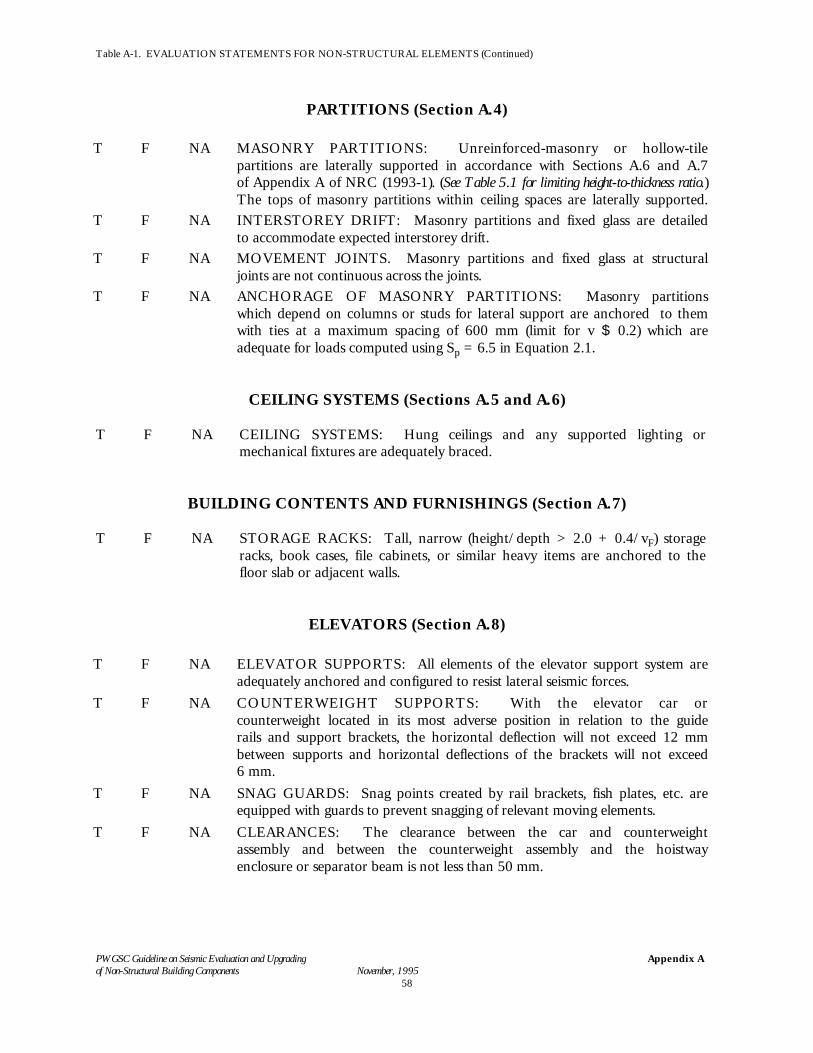
Table A-1. EVALUATION STATEMENTS FOR NON-STRUCTURAL ELEMENTS (Continued)
PWGSC Guideline on Seismic Evaluation and Upgrading of Non-Structural Building Components November, 1995
Appendix A
58
PARTITIONS (Section A.4)
T F NA MASONRY PARTITIONS: Unreinforced-masonry or hollow-tilepartitions are laterally supported in accordance with Sections A.6 and A.7of Appendix A of NRC (1993-1). (See Table 5.1 for limiting height-to-thickness ratio.)The tops of masonry partitions within ceiling spaces are laterally supported.
T F NA INTERSTOREY DRIFT: Masonry partitions and fixed glass are detailedto accommodate expected interstorey drift.
T F NA MOVEMENT JOINTS. Masonry partitions and fixed glass at structuraljoints are not continuous across the joints.
T F NA ANCHORAGE OF MASONRY PARTITIONS: Masonry partitionswhich depend on columns or studs for lateral support are anchored to themwith ties at a maximum spacing of 600 mm (limit for v $ 0.2) which areadequate for loads computed using Sp = 6.5 in Equation 2.1.
CEILING SYSTEMS (Sections A.5 and A.6)
T F NA CEILING SYSTEMS: Hung ceilings and any supported lighting ormechanical fixtures are adequately braced.
BUILDING CONTENTS AND FURNISHINGS (Section A.7)
T F NA STORAGE RACKS: Tall, narrow (height/depth > 2.0 + 0.4/vF) storageracks, book cases, file cabinets, or similar heavy items are anchored to thefloor slab or adjacent walls.
ELEVATORS (Section A.8)
T F NA ELEVATOR SUPPORTS: All elements of the elevator support system areadequately anchored and configured to resist lateral seismic forces.
T F NA COUNTERWEIGHT SUPPORTS: With the elevator car orcounterweight located in its most adverse position in relation to the guiderails and support brackets, the horizontal deflection will not exceed 12 mmbetween supports and horizontal deflections of the brackets will not exceed6 mm.
T F NA SNAG GUARDS: Snag points created by rail brackets, fish plates, etc. areequipped with guards to prevent snagging of relevant moving elements.
T F NA CLEARANCES: The clearance between the car and counterweightassembly and between the counterweight assembly and the hoistwayenclosure or separator beam is not less than 50 mm.
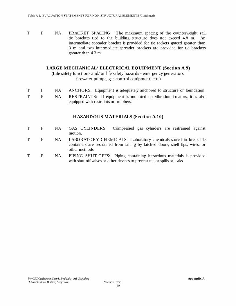
Table A-1. EVALUATION STATEMENTS FOR NON-STRUCTURAL ELEMENTS (Continued)
PWGSC Guideline on Seismic Evaluation and Upgrading of Non-Structural Building Components November, 1995
Appendix A
59
T F NA BRACKET SPACING: The maximum spacing of the counterweight railtie brackets tied to the building structure does not exceed 4.8 m. Anintermediate spreader bracket is provided for tie rackets spaced greater than3 m and two intermediate spreader brackets are provided for tie bracketsgreater than 4.3 m.
LARGE MECHANICAL/ELECTRICAL EQUIPMENT (Section A.9)(Life safety functions and/or life safety hazards - emergency generators,
firewater pumps, gas control equipment, etc.)
T F NA ANCHORS: Equipment is adequately anchored to structure or foundation.T F NA RESTRAINTS: If equipment is mounted on vibration isolators, it is also
equipped with restraints or snubbers.
HAZARDOUS MATERIALS (Section A.10)
T F NA GAS CYLINDERS: Compressed gas cylinders are restrained againstmotion.
T F NA LABORATORY CHEMICALS: Laboratory chemicals stored in breakablecontainers are restrained from falling by latched doors, shelf lips, wires, orother methods.
T F NA PIPING SHUT-OFFS: Piping containing hazardous materials is providedwith shut-off valves or other devices to prevent major spills or leaks.