Embed Size (px)
Citation preview

NUCLEAR ENGINEERING AND TECHNOLOGY, VOL.46 NO.5 OCTOBER 2014 NUCLEAR ENGINEERING AND TECHNOLOGY, VOL.46 NO.5 OCTOBER 2014PB 569
1. INTRODUCTION
Seismic (base) isolation is a relatively mature tech-nology for protecting structures from the effects of moderate and severe earthquake shaking, with key developments in the 1980s and 1990s. Although the technology has been widely deployed for buildings, bridges and certain classes of mission-critical infrastructure, it has yet to be routinely adopted for the seismic protection of safety-related nuclear structures, including nuclear power plants. The limited numbers of applications to nuclear structures to date have been in France and South Africa, for which synthetic rubber (neoprene) bearings, including flat sliders in some installations, have been used. The reasons for the limited use of seismic isolation include a) a significant down-turn in nuclear power plant construction in the thirty-year period from 1980 to 2010, b) construction of nuclear
facilities in regions of low to moderate seismic hazard for which isolation is not necessarily needed, and c) the lack of consensus standards for the analysis and design of seismic isolation systems for nuclear facilities and com-panion requirements for testing of prototype and production bearings.
The nuclear energy renaissance, which began in the United States nearly a decade ago, and somewhat inter-rupted by the Fukushima nuclear accident and the recent availability and low price of natural gas, rekindled interest in the use of seismic isolation to protect nuclear structures from the effects of moderate to severe earthquake shak-ing. This renewed interest led the United States Nuclear Regulatory Commission (NRC) to fund a research project on the seismic isolation of nuclear power plant struc-tures with an emphasis on large light water reactors. One component of the project is the preparation of a NUREG on seismic isolation, which should be published in the coming year. The NUREG will provide guidance on the analysis, design and construction of seismic isolation sys-tems for nuclear power plants. The guidance is virtually identical to the mandatory provisions and commentary that will appear in Section 7.7 of the forthcoming edition of ASCE Standard 4 (ASCE, forthcoming), with the key difference being the definition of the beyond design basis earthquake.
http://dx.doi.org/10.5516/NET.09.2014.715
SEISMIC ISOLATION OF NUCLEAR POWER PLANTS
ANDREW S. WHITTAKER*†‡, MANISH KUMAR§, and MANISH KUMAR§
Department of Civil, Structural and Environmental Engineering, 212 Ketter Hall, University at Buffalo, State University of New York, Buffalo, NY 14260, U.S.A.*Corresponding author. E-mail : [email protected]
Received October 13, 2014
Seismic isolation is a viable strategy for protecting safety-related nuclear structures from the effects of moderate to severe earthquake shaking. Although seismic isolation has been deployed in nuclear structures in France and South Africa, it has not seen widespread use because of limited new build nuclear construction in the past 30 years and a lack of guidelines, codes and standards for the analysis, design and construction of isolation systems specific to nuclear structures.
The funding by the United States Nuclear Regulatory Commission of a research project to the Lawrence Berkeley National Laboratory and MCEER/University at Buffalo facilitated the writing of a soon-to-be-published NUREG on seismic isolation. Funding of MCEER by the National Science Foundation led to research products that provide the technical basis for a new section in ASCE Standard 4 on the seismic isolation of safety-related nuclear facilities. The performance expectations identified in the NUREG and ASCE 4 for seismic isolation systems, and superstructures and substructures are described in the paper. Robust numerical models capable of capturing isolator behaviors under extreme loadings, which have been verified and validated following ASME protocols, and implemented in the open source code OpenSees, are introduced.KEYWORDS : Nuclear Power Plant; Seismic Isolation; Elastomeric Bearings; Sliding Bearings
† Correspondence to: Andrew S. Whittaker, Department of Civil, Structural and Environmental Engineering, 212 Ketter Hall, Uni-versity at Buffalo, State University of New York, Buffalo, NY 14260, U.S.A.
*E-mail: [email protected]‡Professor, Chair and Director of MCEER§PhD Candidates

WHITTAKER et al., Seismic Isolation of Nuclear Power Plants
NUCLEAR ENGINEERING AND TECHNOLOGY, VOL.46 NO.5 OCTOBER 2014 NUCLEAR ENGINEERING AND TECHNOLOGY, VOL.46 NO.5 OCTOBER 2014570 571
Figure 1 identifies components of a seismically iso-lated nuclear structure as characterized in the forthcoming NUREG on seismic isolation (USNRC, forthcoming). The isolators (also termed isolator units and bearings) are assumed installed in a near horizontal plane beneath a basemat that supports the nuclear construction, which is defined as the superstructure. The isolators are installed atop pedestals and a foundation, which is defined as the substructure. The moat is a space in which the isolated superstructure can move without restriction in the event of earthquake shaking. Only horizontal isolation is con-sidered because there are no viable three-dimensional isolation systems available in the marketplace at the time of this writing for large building structures such as nuclear power plants.
The NRC-funded research project is developing knowledge and tools to aid in the implementation of seismic isolation systems in nuclear power plants in the United States. Included in the topics for study are
• Preparation of a NUREG on seismic isolation• Development of verified and validated models for
elastomeric bearings• Development of verified and validated models for
sliding isolation systems• Design procedures for displacement-restraint systems
(or hard stops)• Soil-structure-interaction analysis of seismically isolated
nuclear power plants• Aircraft impact analysis of seismically isolated nuclear
structures
Some of the progress to date is documented in this paper. Kumar et al. (2013a, 2014a) and Kumar et al. (2013b, 2014b) and forthcoming MCEER reports docu-ment products of the project in greater detail than pro-vided here. The following sections of this paper address aspects of the analysis and design of seismic isolation systems for safety-related nuclear structures in the United States. Section 2 introduces the performance expectations for seismic isolators and systems. The types of isolators identified for possible deployment in the United States are discussed in Section 3. Sections 4 and 5 introduce aspects of verified and validated models of elastomeric and sliding isolation systems.
2. PERFORMANCE OBJECTIVES
The performance expectations of Section 1.3 of ASCE 43 (ASCE, 2005) form the basis of the provisions of Section 7.7 of ASCE 4 (ASCE, forthcoming), namely, 1) 1% probability of unacceptable performance for 100% Design Basis Earthquake (DBE) shaking, and 2) 10% probability of unacceptable performance for shaking 150% of design basis. Beyond Design Basis Earthquake (BDBE) shaking is defined as 150% DBE shaking. Consistent with other sections of ASCE 4, seismic demands on the isolated su-perstructure are calculated at the 80th percentile for DBE shaking.
A significant difference between Section 7.7 of ASCE 4 and companion provisions for buildings (ASCE, 2010) and bridges (AASHTO, 2010) is the introduction of a physical stop. The stop, which can be a moat wall, is used to prevent excessive displacement of the isolation system and removes the isolation system from accident sequences involving earthquake shaking. The unrestricted travel (displacement) of the isolation system is defined as the clearance to the stop, CS. The stop need not be provided if the mean annual frequency of failure of the isolation system is so small that it can be screened out as part of a seismic probabilistic risk assessment, noting that screening frequencies will vary by country and regulator.
Table 1 summarizes the performance expectations for seismically isolated nuclear structures per the forthcom-ing edition of ASCE 4 (ASCE, forthcoming). The expec-tations presented in a similar table in the forthcoming NUREG are virtually identical expect for the definition of the beyond design basis earthquake. In the NUREG, beyond design basis shaking is defined as the greater of a) 167% of DBE shaking, and b) a Uniform Hazard Spec-trum calculated for a return period of 100,000 years, all with a lower bound on the spectral acceleration at long periods. Hereafter the paper uses the ASCE 4 definition of BDBE shaking, which can be replaced by the more demanding NUREG definition for isolated nuclear power plants in the United States.
Fig. 1. Seismically Isolated Nuclear Power Plant (USNRC, forthcoming)

WHITTAKER et al., Seismic Isolation of Nuclear Power Plants
NUCLEAR ENGINEERING AND TECHNOLOGY, VOL.46 NO.5 OCTOBER 2014 NUCLEAR ENGINEERING AND TECHNOLOGY, VOL.46 NO.5 OCTOBER 2014570 571
Table 1. Minimum ASCE 4 Performance Expectations for Seismically Isolated Nuclear Facilities

WHITTAKER et al., Seismic Isolation of Nuclear Power Plants
NUCLEAR ENGINEERING AND TECHNOLOGY, VOL.46 NO.5 OCTOBER 2014 NUCLEAR ENGINEERING AND TECHNOLOGY, VOL.46 NO.5 OCTOBER 2014572 573
using procedures presented in Section 1 of ASCE 4 and in the commentary to ASCE 43. If the probabilities of failure at DBE and BDBE shaking exceed the limits of Section 1.3 of ASCE 43, the capacity (strength) of the isolated superstructure is increased until the performance statement is achieved. Adequate performance of the foundation is achieved by designing for forces delivered by the isolation system at displacement CS.
3. ISOLATORS AND ISOLATION SYSTEMS FOR US APPLICATIONS Three types of isolators have been qualified for use in
safety-related nuclear structures in the United States: low damping (natural) rubber (LDR) isolators, lead (natural) rubber (LR) isolators, and the Friction Pendulum (FP) sliding isolator. Each has been tested extensively in the United States, can be modeled for nonlinear response-history analysis, and has been deployed in mission-critical struc-tures in the United States. The mechanical characteristics of these isolators (linear and bilinear) underpin the rules set forth in Section 7.7 of ASCE 4 (and the seismic isolation NUREG). The assumed hysteretic response of LR and FP bearings in a horizontal direction is presented in Figure 2.
Low-damping (LD) elastomeric bearings are composed of alternating layers of natural rubber and steel, and can be modeled as viscoelastic components. The shear modulus of the rubber ranges between 60 psi and 120 psi. The equivalent viscous damping is between 2 and 4% of critical. Lead-rubber (LR) elastomeric bearings are con-structed similarly to low-damping rubber bearings but in-clude a central lead core to dissipate earthquake-induced energy. The hysteresis loop for the LR bearing is bilinear per Figure 2 and defined by a zero-displacement force intercept, Qd, an elastic stiffness, Ku, and a second-slope stiffness, Kd, where W is the supported weight. Sliding bearings with restoring force provided by gravity also have the hysteresis loop of Figure 2. In the Friction Pen-dulum™ (FP) family of bearings, the second-slope stiff-ness is related to the supported weight and the radius
Analysis is performed for DBE and BDBE shaking of an isolated nuclear structure. Results of DBE analysis are used for a) calculating design loads on the superstructure, b) generating in-structure response spectra for design of structures, components and systems (SSCs), and c) es-tablishing displacements for production testing of isola-tors. Results of BDBE analysis are used to a) select the required clearance to the physical stop, and b) establish displacements and forces for prototype testing of isolators.
Four performance statements for achieving the two performance objectives of ASCE 43 were assumed in the writing of Section 7.7 of ASCE Standard 4 (and the seismic isolation NUREG), namely, 1) individual isolators shall suffer no damage in DBE shaking, 2) the probability of the isolated nuclear structure impacting surrounding structure or the moat wall for 100% (150%) DBE shak-ing shall be 1% (10%) or less, 3) individual isolators shall sustain gravity and earthquake-induced axial loads at 90th percentile lateral displacements consistent with 150% DBE shaking, and 4) the probability of unaccepta-ble performance in the isolated superstructure for 100% (150%) DBE shaking shall be 1% (10%) or less. Perfor-mance statement 1 is realized by production testing of each isolator supplied to a project for the 80th percentile DBE displacement and co-existing gravity and earthquake-induced axial forces. Analysis can be used in support of performance statement 2 provided that the isolators are modeled correctly and the ground motion representations are reasonable. Huang et al. (2009, 2012) showed that the 90th percentile displacement for 150% DBE shaking is greater than 99th percentile displacement for DBE shak-ing and so the former is used to establish the clearance to the stop, CS. Performance statement 3 is achieved by prototype testing of a limited number of isolators at a dis-placement equal to CS and co-existing axial forces, noting that an isolation system is composed of tens to hundreds of isolators and that failure of an isolation system would have to involve the simultaneous failure of a significant percentage of the isolators in the system. Performance statement 4 is checked by analysis of the capacity of the isolated superstructure at 100% DBE and BDBE shaking
Fig. 2. Assumed Hysteretic Response of LR and FP Bearings in a Horizontal Direction

WHITTAKER et al., Seismic Isolation of Nuclear Power Plants
NUCLEAR ENGINEERING AND TECHNOLOGY, VOL.46 NO.5 OCTOBER 2014 NUCLEAR ENGINEERING AND TECHNOLOGY, VOL.46 NO.5 OCTOBER 2014572 573
Seismic analysis is performed for design basis shaking. Inelastic action was presumed to develop in those com-ponents detailed for ductile response. Rudimentary eval-uation in the form of static nonlinear (pushover) analysis is performed in selected cases to support safety cases.
The seismic isolation of a safety-related nuclear struc-ture should force inelastic response into the bearings be-neath the superstructure. This concentration of inelastic response into a singleton (the isolation system) led the writers of nuclear standards and regulators in the United States to require explicit analysis for beyond design basis shaking, where such shaking is associated with return periods of between 10,000 and 100,000 years for which seismic spectral demand will be significant, even for regions of low seismic hazard. The need for confirmation of ac-ceptable performance in beyond design basis shaking was reinforced by the Fukushima nuclear accident.
The intense shaking that may be associated with beyond design basis shaking in regions of moderate to high seismic hazard, and the concentration of inelastic action in the bearings of a seismically isolated nuclear structure, led the NRC to support the development of nu-merical models for seismic isolators under extreme load-ings. These models, for elastomeric and sliding isolation systems of the types described in Section 3, were devel-oped as part of the research project introduced previously, which was undertaken by MCEER and the University at Buffalo through a grant administered by Lawrence Berkeley National Laboratory. The following subsections describe the model that was verified and validated for elastomeric isolators. Section 5 presents companion in-formation on sliding isolators.
The models of elastomeric bearings used for analysis of safety-related nuclear structures under design and beyond design basis earthquake shaking may include considerations of
1. Coupled bidirectional motion in horizontal directions2. Coupling of vertical and horizontal motion3. Cavitation and post-cavitation behavior in tension4. Strength degradation under cyclic tensile loading
due to cavitation5. Variation in critical buckling load capacity due to
lateral displacement6. Strength degradation in cyclic shear loading due to
heating of the lead coreA numerical model capable of accommodating these
six behaviors did not exist and was developed as part of the NRC-funded research project, substantially expanding existing capabilities to address extreme earthquake loadings. The model was verified and validated following ASME best practices (ASME, 2006), and implemented in Open-Sees (McKenna et al., 2006) to enable use by researchers and the design professional community. Complete details are provided in Kumar et al. (2013a, 2014a) and pertinent information is presented below.
of curvature of the sliding surfaces. Constantinou et al. (2007) and Naeim and Kelly (1999) provide information on LD, LR and FP seismic isolators. Huang et al. (2008, 2009, 2010, 2012) provide data and information in support of the isolation of nuclear structures and the provisions of Section 7.7 of ASCE 4. Constantinou et al. (1999, 2007), Thompson et al. (2000) and Morgan et al. (2001) provide the data used by Huang et al. (2009, 2012) to characterize the impact of variations in isolator material properties on the displacement response of seismic isolation systems.
Other types of isolators from the three mentioned above are not precluded from use in safety-related nuclear structures in the United States. Rather, the following tasks must be undertaken to qualify another type of isolator (or isolation system) for use in a safety-related nuclear structure in the United States:
1. Dynamic testing of full-scale (prototype) isolators for compressive and tensile axial loads and bidirec-tional horizontal motion at amplitudes of displace-ment expected for beyond design basis ground motions in regions of moderate and high seismic hazard;
2. Development of verified and validated numerical models capable of predicting the results of dynamic testing of prototype isolators, including deteriora-tion of hysteresis due to energy dissipation during earthquakes;
3. Demonstration through basic chemistry, laboratory tests and field applications that the mechanical properties of the isolators do not change by more than 20% over a 50- to 100-year period in the tem-perature range of 40°F to 80°F;
4. System-level testing of the isolation system using three translational components of earthquake ground motion;
5. Verification and validation of numerical tools and codes to predict the seismic response of the isolation system; and
6. Deployment of an isolation system composed of the isolators in mission-critical structures.
Section 7.7 requires tasks 1 through 5 to be performed by experienced persons, independent of the isolator man-ufacturer. Hybrid isolation systems involving different types of bearing (e.g., sliding and elastomeric) are not permitted.
4. NUMERICAL MODELING OF ELASTOMERIC BEARINGS
4.1 IntroductionTraditional nuclear power plant design involving re-
inforced concrete has involved strength design for design basis (or safe shutdown) earthquake shaking and the use of ductile details to provide inelastic deformation capacity in the event of shaking more intense than design basis.

WHITTAKER et al., Seismic Isolation of Nuclear Power Plants
NUCLEAR ENGINEERING AND TECHNOLOGY, VOL.46 NO.5 OCTOBER 2014 NUCLEAR ENGINEERING AND TECHNOLOGY, VOL.46 NO.5 OCTOBER 2014574 575
expected to significantly affect the response of an elas-tomeric bearing. The off-diagonal terms due to coupling between axial and shear, and axial and rotation, are ig-nored. The expression for mechanical properties, includ-ing stiffness and buckling load capacity, are derived us-ing explicit considerations of geometric nonlinearity due to large displacement effects.
The physical model and the mechanical properties of elastomeric bearings in horizontal and vertical direction are discussed here for low damping rubber (LDR) bearing, lead rubber (LR) bearing, and high damping rubber (HDR). 4.3 Behavior under Axial Loading4.3.1 Tension
The phenomenological model is presented in Kumar et al. (2014a) is used here to describe the behavior of elastomeric isolation bearings in tension, including the cavitation and post-cavitation behavior. The cavitation force in an elastomeric bearing is calculated as Fc = 3GAo, where Ao is the bonded rubber area before cavitation in the rubber. The shear modulus, G, is obtained experimentally from testing at a moderate shear strains under nominal axial loads. The post-cavitation force, F, at tensile defor-mation, u, is given by:
where k is the cavitation parameter, which describes the post-cavitation variation of tensile stiffness, and Tr is the total rubber thickness.
Cavitation in an elastomeric bearing is accompa-nied by irreversible damage due to the formation of mi-cro cracks in the volume of rubber. When a bearing is loaded beyond the point of cavitation and unloaded, it returns along a new path and the cavitation strength is
4.2 Physical Model of Elastomeric BearingsThe physical model of an elastomeric bearing is consid-
ered as a two-node, twelve degrees-of-freedom discrete element. The two nodes are connected by six springs that represent the mechanical behavior in the six basic direc-tions of a bearing. The degrees of freedom and discrete spring representation of an elastomeric bearing is shown in Figure 3.
The general form of element force vector, fb, and ele-ment stiffness matrix, Kb, for the element representation presented above is given by Eqn. (1).
The coupling of the two shear springs is considered directly by using a coupled bidirectional model. All other springs are uncoupled. The couplings of the vertical and horizontal directions are considered indirectly by using expressions for mechanical properties in one direction that are dependent on the response parameters in the other direction. Linear uncoupled springs are adopted for the torsion and the two rotational springs as they are not
Fig. 3. Physical Model of an Elastomeric Bearing (Kumar et al., 2014a)
(2)
(1)

WHITTAKER et al., Seismic Isolation of Nuclear Power Plants
NUCLEAR ENGINEERING AND TECHNOLOGY, VOL.46 NO.5 OCTOBER 2014 NUCLEAR ENGINEERING AND TECHNOLOGY, VOL.46 NO.5 OCTOBER 2014574 575
meric bearing obtained from the two-spring model are:
where Ec is the compression modulus of the bearing, uh is the lateral displacement of the bearing, r is the radius of gyration of the bonded rubber area, KH0 is the horizontal stiffness at zero axial load, P is the instantaneous value of axial load, and Pcr is the instantaneous value of critical buckling load. The calculation of Ec for different bearing shapes is discussed in Constantinou et al. (2007).
The load, Pcr, decreases with increasing lateral displace-ment. The area-reduction method considers the dependence of Pcr on lateral displacement and provides conservative results (Buckle and Liu, 1993). The model suggested by Warn et al. (2006, 2007) is considered here, which uses a bilinear approximation of the area-reduction method and takes into account the finite buckling capacity of a bearing at zero overlap area. The reduced critical load is given by:
A mathematical model of an elastomeric bearing in the axial direction is presented in Figure 4. The model uses three unknown parameters: 1) a cavitation param-eter, k, 2) a strength degradation parameter, a, and 3) a damage index, ϕmax.
reduced. Subsequent loading follows the latest unloading path elastically until strain exceeds the past maximum value umax, below which loading has the effect of only opening and closing of existing cavities within the rub-ber. Once loading exceeds the past maximum value of tensile strain, the formation of new cavities leads to in-creased damage, and follows the post cavitation behavior defined previously by Eqn. (2). Upon load reversal, it again traces back a new unloading path and the cavitation strength is further reduced. Unloading paths can be ap-proximated by straight lines between the points of maxi-mum strain (Fmax, umax) and reduced cavitation strength (Fcn, ucn). Points (Fmax, umax) and (Fcn, ucn) change with an increasing number of cycles. To capture this behavior mathematically, a damage index ϕ is defined such that the updated cavitation strength as a function of initial cavita-tion strength is given by the expression, Fcn = Fc(1‒ϕ). The damage index ϕ calculated using:
where a is a strength degradation parameter that defines the rate of damage and ϕmax is the maximum damage that can be expected in a bearing.
4.3.2 CompressionThe two-spring model (Koh and Kelly, 1987), validated
experimentally by Warn et al. (2007), is used here to model the behavior of elastomeric bearing in axial com-pression. The coupling of horizontal and vertical behavior is considered by: 1) dependence of axial stiffness on lateral displacement, and 2) variation of shear stiffness with axial load. The vertical, Kv, and horizontal, KH, stiffness of the elasto-
(3)
(4)
(5)
Fig. 4. Mathematical Model of an Elastomeric Bearing in the Axial Direction (Kumar et al., 2014a)

WHITTAKER et al., Seismic Isolation of Nuclear Power Plants
NUCLEAR ENGINEERING AND TECHNOLOGY, VOL.46 NO.5 OCTOBER 2014 NUCLEAR ENGINEERING AND TECHNOLOGY, VOL.46 NO.5 OCTOBER 2014576 577
unity. The details of the bearings and the values of pa-rameters estimated by calibration against experimental data are presented in Table 1.
The behavior of elastomeric bearings under shear and compression is also well understood, as described previ-ously. Models to capture the degradation in strength of LR bearings due to heating of the lead core under cy-clic shear loading have been developed and validated by Kalpakidis et al. (2010). Herein, these models were coded in OpenSees and verified against analytical solu-tions and validated against the experimental data used by Kalpakidis.
5. NUMERICAL MODELING OF SLIDING BEARINGS
5.1 IntroductionFriction Pendulum™ (FP) bearings have been widely
used to seismically isolate structures in the United States and abroad. This family of hemispherical sliding bearings includes single, double and triple concave variants. The single concave FP bearing, which is studied here, com-prises a sliding surface of polished stainless steel and an articulated slider coated with a PTFE-type composite
4.4 Behavior under Shear LoadingThe behavior of elastomeric bearings in shear is well
established, and two bidirectional hysteretic models are used to model the behavior of elastomeric bearings in shear. The Bouc-Wen model (Park et al., 1986; Wen, 1976) extended for analysis of seismic isolations under bidi-rectional motion by Nagarajaiah et al. (1991) is used for LDR and LR bearings. The model proposed by Grant et al. (2004) is used to model the behavior of HDR bearings. The strength degradation in a LR bearing due to heating of lead core is incorporated using model proposed by Kalpakidis et al. (2010). The effective shear modulus of elastomeric bearings is obtained from experimental data.
4.5 Implementation and Experimental ValidationThe mathematical models of LDR, LR, and HDR bearings
are implemented in OpenSees as three user elements, Elas-tomericX, LeadRubberX and HDR, respectively.
The tensile behavior of elastomeric bearings is val-idated using three sets of experimental data, as shown in Figure 5. The cavitation parameter, k, and the dam-age index, ϕmax, were obtained by visual calibration of the mathematical model with experimental data. The strength degradation parameter, a, was assumed to be
Fig. 5. Comparison of Experimental and Numerical Results for LDR Bearings in Tension (Kumar et al., 2014a)
Constantinou et al. (2007) Iwabe et al. (2000) Warn et al. (2006)
Diameter, mm 250 500 164
Shape factor, S 9.8 33 10.2
Cavitation parameter, k 60 15 20
Max. damage index, ϕmax 0.75 0.75 0.75
Degradation parameter, a 1.0 1.0 1.0
Table 1. Properties of the Bearings used for Experimental Comparison
WHITTAKER et al., Seismic Isolation of Nuclear Power Plants
NUCLEAR ENGINEERING AND TECHNOLOGY, VOL.46 NO.5 OCTOBER 2014 NUCLEAR ENGINEERING AND TECHNOLOGY, VOL.46 NO.5 OCTOBER 2014576 577
5.3 Characterizing the Evolution of the Coefficient of FrictionThe coefficient of friction changes with sliding velocity
due to the viscous nature of the PTFE-type composite coating. The coefficient increases with an increase in ve-locity at small velocities and approaches a constant value at higher velocities (e.g., Mokha et al., 1988). The high-velocity coefficient of friction decreases with increase in axial pressure, whereas the small-velocity coefficient of friction remains almost unaffected (e.g., Constantinou et al., 1993). Expressions to describe the variations in coef-ficient of friction with sliding velocity and axial pressure have been proposed (e.g., Tsopelas et al., 1994; Dao et al., 2013) and incorporated in software such as SAP2000 (CSI, 2013) and OpenSees (McKenna et al., 2006).
The coefficient of friction decreases with increase in the temperature on the sliding surface due to frictional heating, which is attributed to softening in the PTFE-type composite material. There is limited experimental data on variation in the coefficient of sliding friction with temperature on the sliding surface (e.g., Constantinou et al., 2007). The pressure-, temperature- and velocity-dependences of the coefficient of friction are accounted for by factors for pressure kp, temperature, kT, and velocity, kv as follows (Kumar et al., 2014b):
where a determines the rate at which coefficient of fric-tion increases with increase in sliding velocity v, T is tem-perature at the sliding surface, p is the instantaneous axial pressure on the bearing, and po is the reference static axial pressure at which the coefficient of friction is measured at a high velocity of sliding. The factors kv and kp are obtained assuming the small-velocity coefficient of friction is one-half the high-velocity coefficient of friction at all levels of axial pressure. The factor kT is based on the assumption that the ratios of the coefficients of friction at temperatures of -40°C, 20°C and 250°C is 3:2:1. The three factors are discussed in detail in Kumar et al. (2014b).
A reference coefficient of friction, μref, is defined as the coefficient of friction at the axial pressure po, measured at a high-velocity of sliding with the temperature at the sliding surface of To (20°C for this study). The coefficient of friction adjusted for the three effects, μ(p,T,v) , is then computed as the product of μref and the three factors:
The temperature, T, at an instant at a location on the sliding surface is computed by convolving the heat flux history with a decay function (1/√–t ). Three assumptions
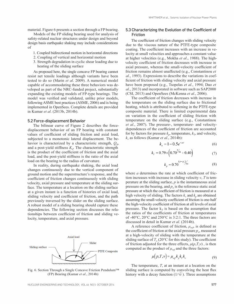
material. Figure 6 presents a section through a FP bearing. Models of the FP sliding bearing used for analysis of
safety-related nuclear structures under design and beyond design basis earthquake shaking may include considerations of
1. Coupled bidirectional motion in horizontal directions2. Coupling of vertical and horizontal motion3. Strength degradation in cyclic shear loading due to
heating of the sliding surfaceAs proposed here, the single concave FP bearing cannot
resist net tensile loadings although variants have been tested to do so (Marin et al. 2009). A numerical model capable of accommodating these three behaviors was de-veloped as part of the NRC-funded project, substantially expanding the existing models of FP-type bearings. The model was verified and validated, unlike prior models, following ASME best practices (ASME, 2006) and is being implemented in OpenSees. Complete details are provided in Kumar et al. (2013b, 2014b).
5.2 Force-displacement BehaviorThe bilinear curve of Figure 2 describes the force-
displacement behavior of an FP bearing with constant values of coefficient of sliding friction and axial load, subjected to a monotonic lateral displacement. The be-havior is characterized by a characteristic strength, Qd, and a post-yield stiffness Kd. The characteristic strength is the product of the coefficient of friction and the axial load, and the post-yield stiffness is the ratio of the axial load on the bearing to the radius of curvature.
In reality, during earthquake shaking, the axial load changes continuously due to the vertical component of ground motion and the superstructure’s response, and the coefficient of friction changes continuously with sliding velocity, axial pressure and temperature at the sliding sur-face. The temperature at a location on the sliding surface at a given instant is a function of histories of axial load, sliding velocity and coefficient of friction, and the path previously traversed by the slider on the sliding surface. A robust model of a sliding bearing should capture these dependencies. The following section discusses the rela-tionships between coefficient of friction and sliding ve-locity, temperature, and axial pressure.
Fig. 6. Section Through a Single Concave Friction Pendulum™ (FP) Bearing (Kumar et al., 2014b)
(6)
(7)
(8)
(9)

WHITTAKER et al., Seismic Isolation of Nuclear Power Plants
NUCLEAR ENGINEERING AND TECHNOLOGY, VOL.46 NO.5 OCTOBER 2014 NUCLEAR ENGINEERING AND TECHNOLOGY, VOL.46 NO.5 OCTOBER 2014578 579
effects of heating only. The peak displacements in the two panels are 290 mm and 310 mm, respectively. The heating effects are much more significant at po = 50 MPa. The peak displacements corresponding to the two friction models are 290 mm (Figure 8b) and 510 mm (Figure 8d), respectively. The velocity and pressure dependencies of the coefficient of friction do not significantly affect the peak displacements or the transmitted forces, as described in Kumar et al. (2014b).
6. CLOSING REMARKS
Seismic isolation is a viable strategy for protecting safety-related nuclear structures from the effects of moder-ate to severe earthquake shaking but it has not been widely adopted because of limited nuclear construction in the past 30 years and a lack of guidelines, codes and standards for the analysis, design and construction of isolation systems specific to nuclear structures.
Research funding from the United States Nuclear Regulatory Commission to the Lawrence Berkeley Na-tional Laboratory and MCEER/University at Buffalo has facilitated the writing of a soon-to-be-published NUREG on seismic isolation. Funding of MCEER by the National Science Foundation led to research products that provide the technical basis for a new section in ASCE Standard 4 on the seismic isolation of safety-related nuclear fa-cilities. The performance expectations identified in the NUREG and ASCE 4 for seismic isolation systems, and superstructures and substructures, are identified and their technical bases are provided. Key to the implementation of the technology is the development of verified and vali-dated numerical models of isolators capable of capturing behaviors under extreme loadings. Such models are in-
are made: 1) the heat generated at the sliding surface is transferred to the sliding surface only, 2) conditions of an infinite half-space for heat conduction are realized, and 3) temperature at the center of the sliding surface represents the temperature at the sliding surface. These assumptions are discussed in detail in Constantinou et al. (2007) and Kumar et al. (2014b). The heat flux at a location is the product of coefficient of friction, sliding velocity and axial pressure when the slider is over the location and zero otherwise.
Figure 7a plots the coefficient of friction against tem-perature and Figure 7b plots the coefficient of friction against axial pressure for three values of sliding velocity (=1000 mm/s, 10 mm/s and 0.001 mm/s). If the temperature at the sliding surface rises from 20°C to a maximum of 250°C, the high-velocity coefficient of friction will vary between 0.06 and 0.03, for a constant axial pressure. Sim-ilarly, if the axial pressure on the bearing ranges between 2 MPa and 18 MPa, the high-velocity coefficient of friction will vary between 0.064 and 0.057.
5.4 Intra-earthquake Evolution of the Coefficient of FrictionSingle FP bearings with a sliding period of 3 s, μref
of 0.06, and po of 10 MPa and 50 MPa were subjected to a set of thirty ground motions representing seismic hazard with a return period of 10,000 years for the site of the Diablo Canyon nuclear generating station. Infor-mation on these ground motions is provided in Huang et al. (2009). Figure 8a plots the force-displacement re-sponse in a horizontal direction for the bearing with po of 10 MPa and friction at the sliding surface described by Coulomb model (kp=1; kT =1; kv =1) subjected to one of the 30 ground motions. Figure 8c presents the response for the case where the friction model accounts for the
Fig. 7. Variation in the Coefficient of Friction with Sliding Velocity, Axial Pressure and Temperature at the Sliding Surface(Kumar et al., 2014b)

WHITTAKER et al., Seismic Isolation of Nuclear Power Plants
NUCLEAR ENGINEERING AND TECHNOLOGY, VOL.46 NO.5 OCTOBER 2014 NUCLEAR ENGINEERING AND TECHNOLOGY, VOL.46 NO.5 OCTOBER 2014578 579
"Seismic analysis of safety-related nuclear structures." ASCE/SEI 4-**, Reston, VA.
[ 6 ] American Society of Mechanical Engineers (ASME). (2006). "Guide for verification and validation in computational solid mechanics." ASME V&V 10–2006, New York, NY.
[ 7 ] Buckle, I. G., and Liu, H. (1993). "Stability of elastomeric seismic isolation systems." Proceedings: Seminar on Seismic Isolation, Passive Energy Dissipation, and Control, Redwood City, California, 293-305.
[ 8 ] Computers and Structures Incorporated (CSI). (2013). "Computer program SAP2000, Version 15.2.1." Berkeley, California.
[ 9 ] Constantinou, M. C., Tsopelas, P., Kim, Y.-S., and Okamoto, S. (1993). "NCEER-Taisei Corporation research program on sliding seismic isolation systems for bridges: Experimental and analytical study of a Friction Pendulum System (FPS)." NCEER-93-0020, National Center for Earthquake Engineering Research, Buffalo, NY.
[ 10 ] Constantinou, M. C., Tsopelas, P., Kasalanati, A., and Wolff, E. D. (1999). "Property modification factors for seismic isolation bearings." MCEER-99-0012, Multidisciplinary Center for Earthquake Engineering Research, Buffalo, NY.
[ 11 ] Constantinou, M. C., Whittaker, A. S., Kalpakidis, Y., Fenz, D. M., and Warn, G. P. (2007). "Performance of seismic isolation hardware under service and seismic loading." MCEER-07-0012, Multidisciplinary Center for Earthquake Engineering Research, Buffalo, NY.
[ 12 ] Dao, N. D., Ryan, K. L., Sato, E., and Sasaki, T. (2013). "Predicting the displacement of Triple Pendulum™ bearings in a full-scale shaking experiment using a three-dimensional element." Earthquake Engineering & Structural Dynamics, 42(11), 1677-1695.
troduced in the paper and have been implemented into the open source code OpenSees as new user elements.
ACKNOWLEDGEMENTSThis research project is supported by a grant to
MCEER from the United States Nuclear Regulatory Commission and the Lawrence Berkeley National Labo-ratory (LBNL). This financial support is gratefully ac-knowledged. The authors thank Dr. Robert Budnitz of LBNL for his guidance on the project, Professor Michael Constantinou of the University at Buffalo for his advice on modeling elastomeric and sliding isolators, and former graduate students Dr. Ioannis Kalpakidis of Energo En-gineering and Dr. Gordon Warn of Penn State University for providing test data on elastomeric bearings.
REFERENCES_______________________________[ 1 ] American Association of State Highway and Transportation
Officials (AASHTO). (2010). "Guide specifications for seismic isolation design." Washington, D.C.
[ 2 ] American Concrete Institure (ACI). (2006). "ACI 349-06: Code requirements for nuclear safety-related structures." Farmington Hills, MI.
[ 3 ] American Society of Civil Engineers (ASCE). (2005). "Seismic design criteria for structures, systems, and components in nuclear facilities." ASCE/SEI 43-05, Reston, VA.
[ 4 ] American Society of Civil Engineers (ASCE). (2010). "Minimum design loads for buildings and other structures." ASCE 7-10, Reston, VA
[ 5 ] American Society of Civil Engineers (ASCE). (forthcoming).
Fig. 8. Force-displacement Histories of an FP Bearing in the Y Direction with Sliding Isolation Period of 3 s and Reference Coefficient of Friction 0.06, Subjected to an Earthquake Ground Motion

WHITTAKER et al., Seismic Isolation of Nuclear Power Plants
NUCLEAR ENGINEERING AND TECHNOLOGY, VOL.46 NO.5 OCTOBER 2014 NUCLEAR ENGINEERING AND TECHNOLOGY, VOL.46 NO.5 OCTOBER 2014580 PB
[ 25 ] Marin, C. C., Whittaker, A. S., and Constantinou, M. C. (2009). "Experimental study of the XY-Friction Pendulum bearing for bridge applications." Journal of Bridge Engineering, Vol. 14, No. 3, pp. 193-202.
[ 26 ] McKenna, F., Fenves, G., and Scott, M. (2006). "Computer Program OpenSees: Open system for earthquake engineering simulation." Pacific Earthquake Engineering Center, University of California, Berkeley, CA., (http://opensees.berkeley.edu).
[ 27 ] Mokha, A., Constantinou, M. C., and Reinhorn, A. M. (1988). "Teflon bearings in aseismic base isolation: experimental studies and mathematical modeling." NCEER-88-0038, National Center for Earthquake Engineering Research, Buffalo, NY.
[ 28 ] Morgan, T., Whittaker, A. S., and Thompson, A. C. (2001). "Cyclic behavior of high-damping rubber bearings." Proceedings: Fifth World Congress on Joints, Bearings and Seismic Systems for Concrete Structures, American Concrete Institute, Rome, Italy.
[ 29 ] Naeim, F., and Kelly, J. M. (1999). "Design of seismic isolated structures: from theory to practice." John Wiley & Sons, NY.
[ 30 ] Nagarajaiah, S., Reinhorn, A. M., and Constantinou, M. C. (1991). "Nonlinear dynamic analysis of 3D-base-isolated structures." Journal of Structural Engineering, 117(7), 2035-2054.
[ 31 ] Park, Y. J., Wen, Y. K., and Ang, A. H. S. (1986). "Random vibration of hysteretic systems under bi-directional ground motions." Earthquake Engineering & Structural Dynamics, 14(4), 543-557.
[ 32 ] Thompson, A. C. T., Whittaker, A. S., Fenves, G. L., and Mahin, S. A. (2000). "Property modification factors for elastomeric seismic isolation bearings." Proceedings: 12th World Conference on Earthquake Engineering, Auckand, New Zealand.
[ 33 ] Tsopelas, P. C., Constantinou, M. C., and Reinhorn, A. M. (1994). "3D-BASIS-ME: Computer program for nonlinear dynamic analysis of seismically isolated single and multiple structures and liquid storage tanks." NCEER-94-0010, National Center for Earthquake Engineering Research, Buffalo, NY.
[ 34 ] United States Nuclear Regulatory Commission (USNRC). (forthcoming). "Technical considerations for seismic isolation of nuclear facilities." NUREG-**, Washington DC.
[ 35 ] Warn, G. P., and Whittaker, A. S. (2006). "A study of the coupled horizontal-vertical behavior of elastomeric and lead-rubber seismic isolation bearings." MCEER-06-0011, Multidisciplinary Center for Earthquake Engineering Research, Buffalo, NY.
[ 36 ] Warn, G. P., Whittaker, A. S., and Constantinou, M. C. (2007). "Vertical stiffness of elastomeric and lead-rubber seismic isolation bearings." Journal of Structural Engineering, 133(9), 1227-1236.
[ 37 ] Wen, Y.-K. (1976). "Method for random vibration of hysteretic systems." Journal of the Engineering Mechanics Division, 102(2), 249-263.
[ 13 ] Grant, D. N., Fenves, G. L., and Whittaker, A. S. (2004). "Bidirectional modeling of high-damping rubber bearings." Journal of Earthquake Engineering, 8, 161-185.
[ 14 ] Huang, Y.-N., Whittaker, A. S., and Luco, N. (2008). "Performance assessment of conventional and base-isolated nuclear power plants for earthquake and blast loadings." MCEER-08-0019, Multidisciplinary Center For Earthquake Engineering Research, Buffalo, NY.
[ 15 ] Huang, Y.-N., Whittaker, A. S., Kennedy, R. P., and Mayes, R. L. (2009). "Assessment of base-isolated nuclear structures for design and beyond-design basis earthquake shaking." MCEER-09-0008, Multidisciplinary Center For Earthquake Engineering Research, Buffalo, NY.
[ 16 ] Huang, Y.-N., Whittaker, A. S., and Luco, N. (2010). "Seismic performance assessment of base-isolated safety-related nuclear structures." Earthquake Engineering and Structural Dynamics, 39(13), 1421-1442.
[ 17 ] Huang, Y.-N., Whittaker, A. S., Kennedy, R. P., and Mayes, R. L. (2012). "Response of base-isolated nuclear structures for design and beyond-design basis earthquake shaking." Earthquake Engineering & Structural Dynamics, 42(3), 339–356.
[ 18 ] Iwabe, N., Takayama, M., Kani, N., and Wada, A. (2000). "Experimental study on the effect of tension for rubber bearings." Proceedings: 12th World Conference on Earthquake Engineering, New Zealand.
[ 19 ] Kalpakidis, I. V., Constantinou, M. C., and Whittaker, A. S. (2010). "Modeling strength degradation in lead-rubber bearings under earthquake shaking." Earthquake Engineering and Structural Dynamics, 39(13), 1533-1549.
[ 20 ] Koh, C. G., and Kelly, J. M. (1987). "Effects of axial load on elastomeric isolation bearings." EERC/UBC 86/12, Earthquake Engineering Research Center, University of California, Berkeley, CA.
[ 21 ] Kumar, M., Whittaker, A., and Constantinou, M. (2013a). "Mechanical properties of elastomeric seismic isolation bearings for analysis under extreme loadings." Transactions, 22nd International Conference on Structural Mechanics in Reactor Technology (SMiRT 22), San Francisco, California.
[ 22 ] Kumar, M., Whittaker, A. S., and Constantinou, M. C. (2013b). "Response prediction for friction pendulum bearings considering the dependence of friction on axial pressure, temperature and velocity." Transactions, 22nd International Conference on Structural Mechanics in Reactor Technology (SMiRT 22), San Francisco, CA.
[ 23 ] Kumar, M., Whittaker, A., and Constantinou, M. C. (2014a). "An advanced numerical model of elastomeric seismic isolation bearings." Earthquake Engineering & Structural Dynamics, Published online, DOI: 10.1002/eqe.2431.
[ 24 ] Kumar, M., Whittaker, A., and Constantinou, M. C. (2014b). "Friction in sliding isolation bearings." Earthquake Engineering & Structural Dynamics, Paper submitted for review and possible publication.

![SEISMIC ROOF ISOLATION OF HALKAPINAR … · most efficient seismic isolation solution for the Halkapınar Gymnasium. In this thesis, theory of seismic isolation, ... [18] (From AASHTO](https://img.pdfslide.net/doc/110x75/5b5ba6ce7f8b9a905c8e7903/seismic-roof-isolation-of-halkapinar-most-efficient-seismic-isolation-solution.jpg)