Embed Size (px)
DESCRIPTION
Seismic Provisions Handouts_4per_Landscape
Citation preview
AISC Live Webinar: Introduction to the 2005 AISC Seismic Provisions
American Institute of Steel Construction 1
I-1
Thank you for joining our live Thank you for joining our live webinarwebinar today.today.We will begin shortly. Please standby.
Thank you.
Need Help? Call ReadyTalk Support: 800.843.9166
TodayToday’’s audio will be broadcast through the internet.s audio will be broadcast through the internet.Alternatively, to hear the audio through the phone, dial 800.920.4316800.920.4316..
International callers, dial 00+1+303.223.0116. For additional support, please press *0 and you will be connected to a live operator.
Today’s meeting will begin shortly.
TodayToday’’s live s live webinarwebinar will begin shortly. will begin shortly. Please standby.Please standby.
As a reminder, all lines have been muted. Please type any questions or comments through the Chat feature on the left portion of your screen.
Today’s audio will be broadcast through the internet. Alternatively, dial 800.920.4316800.920.4316 to hear the audio through the phoneto hear the audio through the phone. .
International callers, dial 00+1+212+231+2909.For additional support, press *0 and you will be connected to a live operator.
Today’s AISC Live Webinar
Introduction to the 2005 AISC Seismic Provisions
written and presented by
Thomas A. Sabol, Ph. D., S.E.Principal, Englekirk & Sabol
Consulting Engineers, Inc, Los Angeles, CA.
AISC Live Webinar: Introduction to the 2005 AISC Seismic Provisions
American Institute of Steel Construction 2
I-5
Introduction to 2005 AISC Seismic Provisions
Part I
WebinarVersion
I-6
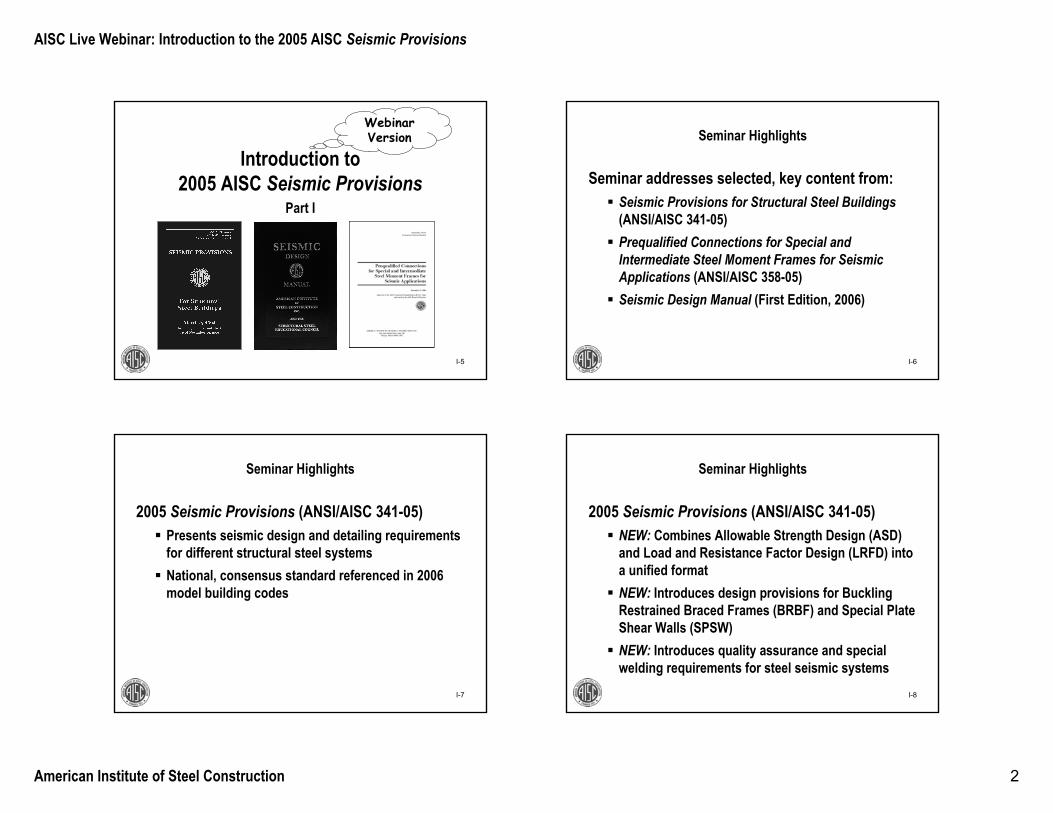
Seminar Highlights
Seminar addresses selected, key content from:Seismic Provisions for Structural Steel Buildings(ANSI/AISC 341-05)Prequalified Connections for Special and Intermediate Steel Moment Frames for Seismic Applications (ANSI/AISC 358-05)Seismic Design Manual (First Edition, 2006)
I-7
Seminar Highlights
2005 Seismic Provisions (ANSI/AISC 341-05)Presents seismic design and detailing requirements for different structural steel systemsNational, consensus standard referenced in 2006 model building codes
I-8
Seminar Highlights
2005 Seismic Provisions (ANSI/AISC 341-05)NEW: Combines Allowable Strength Design (ASD) and Load and Resistance Factor Design (LRFD) into a unified formatNEW: Introduces design provisions for Buckling Restrained Braced Frames (BRBF) and Special Plate Shear Walls (SPSW)NEW: Introduces quality assurance and special welding requirements for steel seismic systems
AISC Live Webinar: Introduction to the 2005 AISC Seismic Provisions
American Institute of Steel Construction 3
I-9
Seminar Highlights
Moment Frame Connection Prequalification Standard (ANSI/AISC 358-05)
First national consensus standard to replace FEMA 350 for design of moment frame connections(FEMA 350 is a moment frame connection design guideline developed after 1994 Northridge Earthquake based on multi-year research program)
I-10
Seminar HighlightsMoment Frame Connection Prequalification
Standard (ANSI/AISC 358-05)Provides design requirements, design limitations, and design procedures for:
• Reduced Beam Section (RBS) • Bolted End Plate (BEP) connections
Supplement 1 (2009) contains liberalized requirements for BEP and new provisions for Bolted Flange Plate (BEP), Welded Unreinforced Flange-Welded Web (WUF-W), and Kaiser
Bolted Bracket (KBB)
I-11
Seminar Highlights
Seismic Design Manual (Second Printing, 2006)Resource to help designers apply 2005 Seismic Provisions and Prequalified Connection StandardContains a copy of 2005 Seismic Provisions and Prequalified Connection Standard
But, without Supplement 1
I-12
Seminar Highlights
Seismic Design Manual (Second Printing, 2006)Provides practical examples to illustrate
• basic seismic concepts in structural steel • design examples for braced frames, moment
frames, and other system components
AISC Live Webinar: Introduction to the 2005 AISC Seismic Provisions
American Institute of Steel Construction 4
I-13
Questions
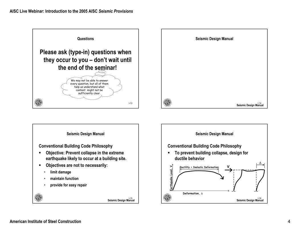
Please ask (type-in) questions when they occur to you – don’t wait until
the end of the seminar!
We may not be able to answer every question, but all of them
help us understand what content might not be
sufficiently clear.
I-14
Seismic Design Manual
Seismic Design Manual
I-15
Seismic Design Manual
Conventional Building Code Philosophy Objective: Prevent collapse in the extreme earthquake likely to occur at a building site. Objectives are not to necessarily:
• limit damage• maintain function• provide for easy repair
Seismic Design ManualI-16
Seismic Design Manual
Conventional Building Code Philosophy To prevent building collapse, design for ductile behavior
Seismic Design Manual
VEa
rthq
uake
Loa
d, V Ductility = Inelastic Deformation
Deformation, Δ
Δ

AISC Live Webinar: Introduction to the 2005 AISC Seismic Provisions
American Institute of Steel Construction 5
I-17
Completely elastic response
Seismic Design Manual
As required elastic strength goes down (i.e. larger “R”-factor) required inelastic deformation increases
Seismic Design Manual
V
Eart
hqua
ke L
oad,
V
Deformation, Δ
Δ
Δyield Δmax
Velastic
0.75Velastic
0. 5Velastic
0.25Velastic
As required elastic strength goes down (i.e. larger “R”-factor) required inelastic deformation increases
I-18
Completely elastic response
Seismic Design Manual
Seismic Design Manual
V
Eart
hqua
ke L
oad,
V
Deformation, Δ
Δ
Δyield Δmax
Velastic
0.75Velastic
0. 5Velastic
0.25Velastic
As elastic design load decreases, required inelastic deformation increases
I-19
Seismic Design Manual
Seismic Provisions attempt to develop ductile behavior in steel seismic systems
Ductility is provided by yieldingFracture or instability reflect non-ductile behavior
Seismic Design Manual
V
Eart
hqua
ke L
oad,
V
Ductility = Inelastic Deformation
Deformation, Δ
Δ
Failure (fracture or instability)
I-20
Seismic Design Manual
Seismic Provisions attempt to develop ductile behavior in steel seismic systemsChoose frame elements ("fuses") that will yield in an earthquake:
• Beams in moment resisting frames• Braces in concentrically braced frames• Links in eccentrically braced frames, etc.
Seismic Design Manual
AISC Live Webinar: Introduction to the 2005 AISC Seismic Provisions
American Institute of Steel Construction 6
I-21
Seismic Design Manual
Seismic Provisions attempt to develop ductile behavior in steel seismic systemsDetail "fuses" to sustain large inelastic deformationsprior to the onset of fracture or instability
• Detail fuses for ductility
Seismic Design ManualI-22
Seismic Design Manual
Seismic Provisions attempt to develop ductile behavior in steel seismic systemsDesign all other frame elements to be stronger than the fuses
• All other frame elements develop the plastic capacity of the fuses
• Generally, this means other elements remain elastic or nearly elastic
Seismic Design Manual
I-23
Seismic Design Manual
Alternatively, in some areas of the country, you may design to a higher force (i.e. use R = 3) and you do not have to detail the seismic elements as required by the Seismic Provisions.
Thus, you must either• Use R > 3 and seismic detailing from Seismic
Provisions• Use R = 3 and you need not use seismic detailing
Seismic Design Manual
You can’t use R > 3 and skip the
seismic detailing!
I-24
Seismic Provisions for Structural Steel Buildings
Seismic Provisions
AISC Live Webinar: Introduction to the 2005 AISC Seismic Provisions
American Institute of Steel Construction 7
I-25
Seismic Provisions for Structural Steel Buildings
Organization of the Seismic Provisions DocumentPart I: LRFD and ASD ProvisionsPart II: Composite Structural Steel and Reinforced Concrete BuildingsCommentary for Part I and Part II
Seismic Provisions
An unappreciated resource in the AISC
Seismic Provisions
I-26
Seismic Provisions for Structural Steel Buildings
Major emphases of this SeminarPart I of AISC Seismic ProvisionsMoment frames and braced framesR > 3 seismic system requirements
Seismic Provisions
I-27
Seismic Provisions for Structural Steel Buildings
Part I ContentsSymbolsGlossary1. Scope2. Referenced Specifications, Codes and Standards3. General Seismic Design Requirements
Seismic ProvisionsI-28
Seismic Provisions for Structural Steel Buildings
Part I Contents (continued)
4. Loads, Load Combinations, and Nominal Strengths5. Structural Design Drawings and Specifications, Shop Drawings and Erection Drawings6. Materials7. Connections, Joints and Fasteners8. Members
Seismic Provisions
AISC Live Webinar: Introduction to the 2005 AISC Seismic Provisions
American Institute of Steel Construction 8
I-29
Seismic Provisions for Structural Steel Buildings
Part I Contents (continued)Provisions Specific to Steel Seismic Systems
9. Special Moment Frames (SMF)10. Intermediate Moment Frames (IMF)11. Ordinary Moment Frames (OMF)12. Special Truss Moment Frames (STMF)
Seismic Provisions
Moment frame
systems
I-30
Seismic Provisions for Structural Steel Buildings
Part I Contents (continued)Provisions Specific to Steel Seismic Systems
13. Special Concentrically Braced Frames (SCBF)14. Ordinary Concentrically Braced Frames (OCBF)15. Eccentrically Braced Frames (EBF)16. Buckling-Restrained Braced Frames (BRBF)17. Special Plate Shear Walls (SPSW)
Seismic Provisions
Braced systems
New shear wall system
I-31
Seismic Provisions for Structural Steel Buildings
Part I Contents (continued)Other Sections/Appendices
18. Quality Assurance PlanAppendix P: Prequalification of Beam-to-Column and Link-to-Column ConnectionsAppendix Q: Quality Assurance PlanAppendix R: Seismic Design Coefficients ad Approximate Period Parameters
Seismic ProvisionsI-32
Seismic Provisions for Structural Steel Buildings
Part I Contents (continued)Other Sections/Appendices
Appendix S: Qualifying Cyclic Tests of Beams-to-Column and Link-to-Column ConnectionsAppendix T: Qualifying Cyclic Tests of Buckling-Restrained BracesAppendix W: Welding ProvisionsAppendix X: Weld Metal/Welding Procedure Specification Notch Toughness Verification Test
Seismic Provisions
AISC Live Webinar: Introduction to the 2005 AISC Seismic Provisions
American Institute of Steel Construction 9
I-33
Glossary
Terms listed in glossary are generally italicized where they first appear in a subsection
Seismic ProvisionsI-34
1. Scope
Seismic Provisions intended for use in buildings and “other structures”
“Other structures” have vertical and lateral systems similar to buildings and are designed, fabricated and erected in a manner similar to buildingsSeismic Provisions apply when R > 3 or when otherwise required by the building code
Seismic Provisions
e.g. for cantilevered column systems where
R = 2.2
I-35
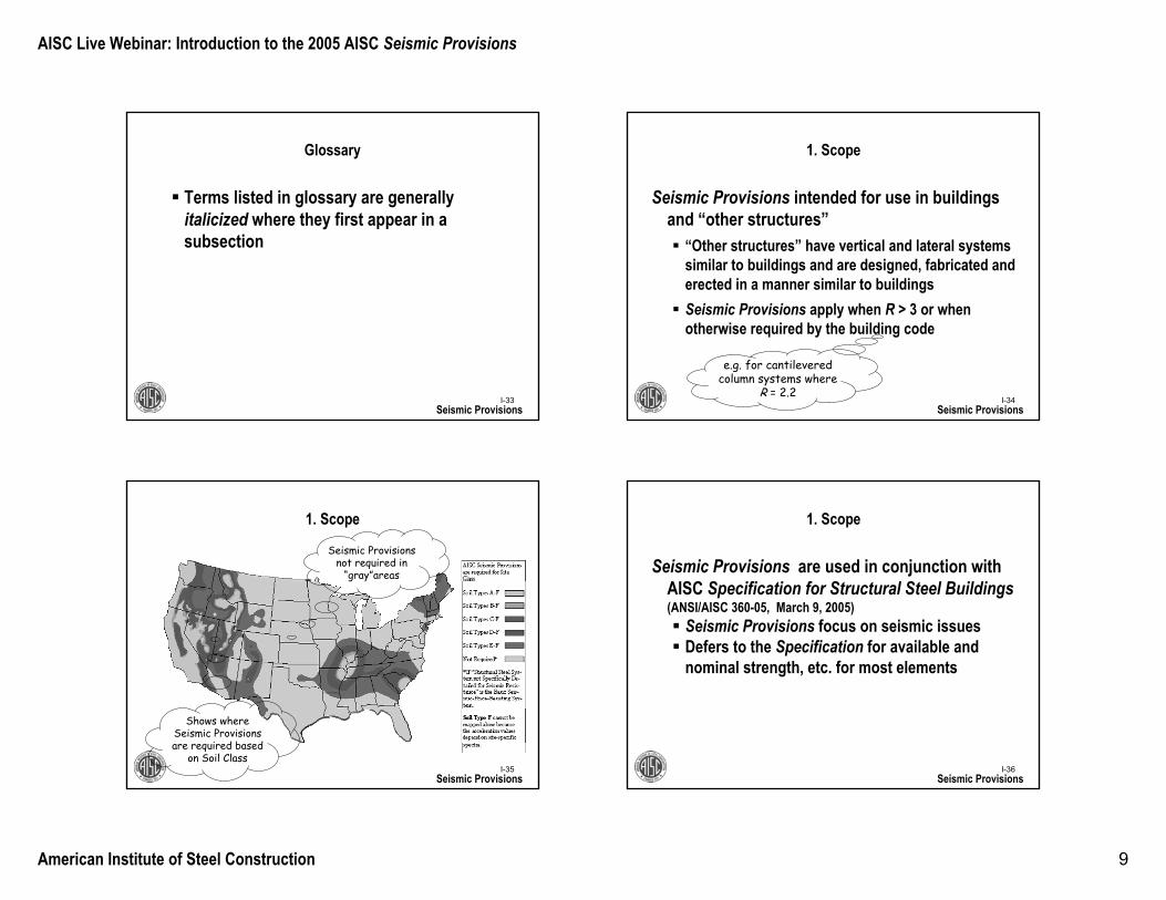
1. Scope
Seismic Provisions
Shows where Seismic Provisions are required based
on Soil Class
Seismic Provisions not required in
“gray”areas
I-36
1. Scope
Seismic Provisions are used in conjunction with AISC Specification for Structural Steel Buildings (ANSI/AISC 360-05, March 9, 2005)
Seismic Provisions focus on seismic issuesDefers to the Specification for available and nominal strength, etc. for most elements
Seismic Provisions
AISC Live Webinar: Introduction to the 2005 AISC Seismic Provisions
American Institute of Steel Construction 10
I-37
3. General Seismic Design Requirements
Seismic Provisions defer to applicable building code for
Required seismic strength (see slides on Section 4 for exception)Determination of Seismic Design Categories and OccupancyDesign story drift limits
Seismic ProvisionsI-38
4. Loads, Load Combinations, and Nominal Strengths
Seismic Provisions
I-39
4.1. Loads and Load Combinations
Applicable Building CodeDetermines loads and load combinations for required strength of steel seismic systems using provisions in ASCE 7 except Seismic Provisions may impose additional requirements…
Seismic ProvisionsI-40
4.1. Loads and Load Combinations
Applicable Building Code… except Seismic Provisions may impose additional requirements:
When demand from one member can impose higher loads on another member
0.9D + 1.0E (note that E is assumed to have both a positive and negative sign in this combination)
Seismic Provisions
Investigates presence of “net tension”
AISC Live Webinar: Introduction to the 2005 AISC Seismic Provisions
American Institute of Steel Construction 11
I-41
4.1. Loads and Load Combinations
Applicable Building CodeDetermines overstrength factor, Ωo, to multiply horizontal earthquake load, E, when amplified seismic loads are required by the Seismic ProvisionsΩo is estimate of maximum load that can be imposed on a member by another member
Seismic Provisions
This is not the same as Ω (ASD
Factor of Safety)
I-42
4.1. Loads and Load Combinations
Applicable Building CodeOverstrength factor, Ωo, is estimate of maximum loadthat can be imposed on a member by another member
Pseudo “mechanism load”Tries to account for “unaccounted strength”in seismic system
Seismic Provisions
I-43
5. Structural Design Drawings and Specifications, Shop Drawings, and Erection Drawings
Seismic Provisions
Significant change in 2005 Seismic
Provisions
I-44
5.1 Structural Design Drawings and Specifications
The engineer, not the contractor or inspector, is in the best position to know which components are part of the seismic system and which require special consideration
The engineer must communicate the design intentto the contractor and inspector via the structural design drawings
Seismic Provisions
AISC Live Webinar: Introduction to the 2005 AISC Seismic Provisions
American Institute of Steel Construction 12
I-45
5.1 Structural Design Drawings and Specifications
Structural design drawings need to indicateType of Seismic Load Resisting System (SLRS) (e.g. SMF, EBF, etc.)Members and connections that are part of SLRSConfiguration of the connections
Seismic ProvisionsI-46
5.1 Structural Design Drawings and Specifications
Structural design drawings need to indicateMember/connection material specifications and sizesLocation of “demand critical welds”
Sections 5.2 and 5.3 contain similar requirements for shop and erection drawings
Seismic Provisions
Welds likely to experience inelastic
demand – See Section 7.3b
I-47
Locations in seismic system with special
limitations related to fabrication and
attachments – See Section 7.4
5.1 Structural Design Drawings and Specifications
Structural design drawings need to indicateLocation and dimensions of protected zonesWelding requirements as specified in Appendix W, Section W2.1
Seismic ProvisionsI-48
6. Materials
Seismic Provisions
AISC Live Webinar: Introduction to the 2005 AISC Seismic Provisions
American Institute of Steel Construction 13
I-49
6.1. Material Specifications
Specified minimum yield strength (Fy) for members with anticipated inelastic behavior shall not exceed 50 ksi (unless suitability is proven by testing)
Limitation does not apply to columns where inelastic behavior is assumed to be limited to column base.
Seismic ProvisionsI-50
e.g. Ru = RyFyAg
6.2 Material Properties for Determination of Required Strength of Members and Connections
When specified in Seismic Provisions, required strength shall be based on “Expected Yield Strength,” RyFy, of an adjoining member
Underlying assumption is that actual yield strength is greater than minimum specified strengthIn seismic design, it is not appropriate (i.e. not “conservative”) to underestimate demand on one member created by another
Seismic Provisions
I-51
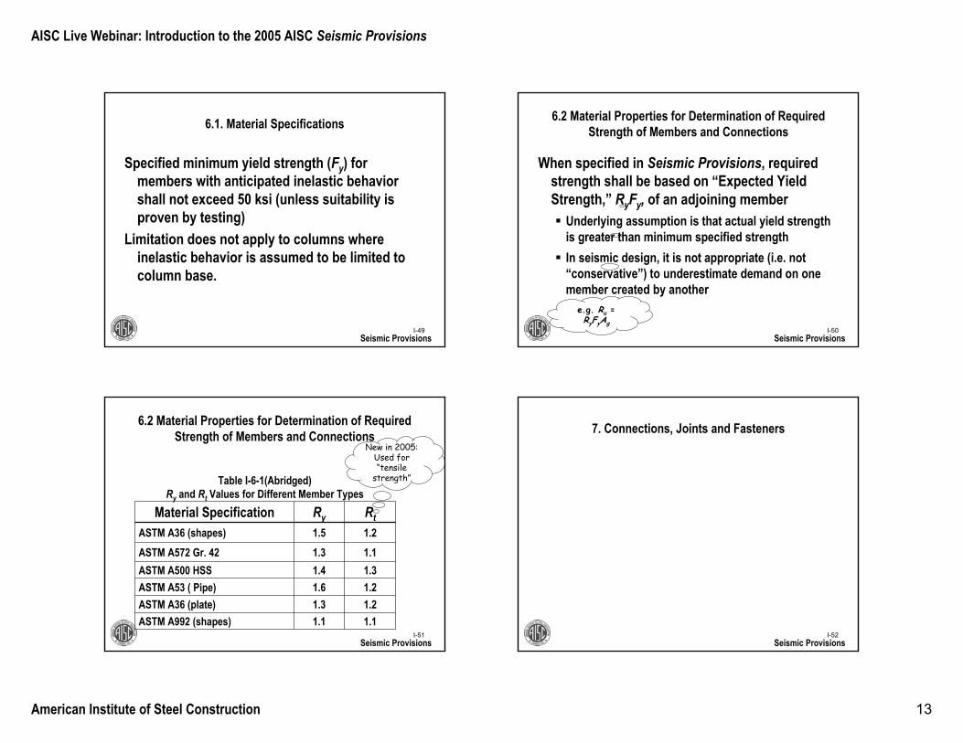
6.2 Material Properties for Determination of Required Strength of Members and Connections
Material Specification Ry RtASTM A36 (shapes) 1.5 1.2ASTM A572 Gr. 42 1.3 1.1ASTM A500 HSS 1.4 1.3ASTM A53 ( Pipe) 1.6 1.2ASTM A36 (plate) 1.3 1.2ASTM A992 (shapes) 1.1 1.1
Table I-6-1(Abridged)Ry and Rt Values for Different Member Types
Seismic Provisions
New in 2005: Used for “tensile
strength”
I-52
7. Connections, Joints and Fasteners
Seismic Provisions
AISC Live Webinar: Introduction to the 2005 AISC Seismic Provisions
American Institute of Steel Construction 14
Seismic Provisions
7.2. Bolted Joints
All bolts in SLRS shall be pretensioned high-strength bolts (i.e. no A307 bolts)
Faying surfaces shall be prepared as slip-critical with a Class A surfaceEven though you prepare joint as if it were “slip-critical,” you may use the higher bolt “bearing” values (with some exceptions)
Faying surface is where steel plies come into
contact
I-54
7.2. Bolted Joints
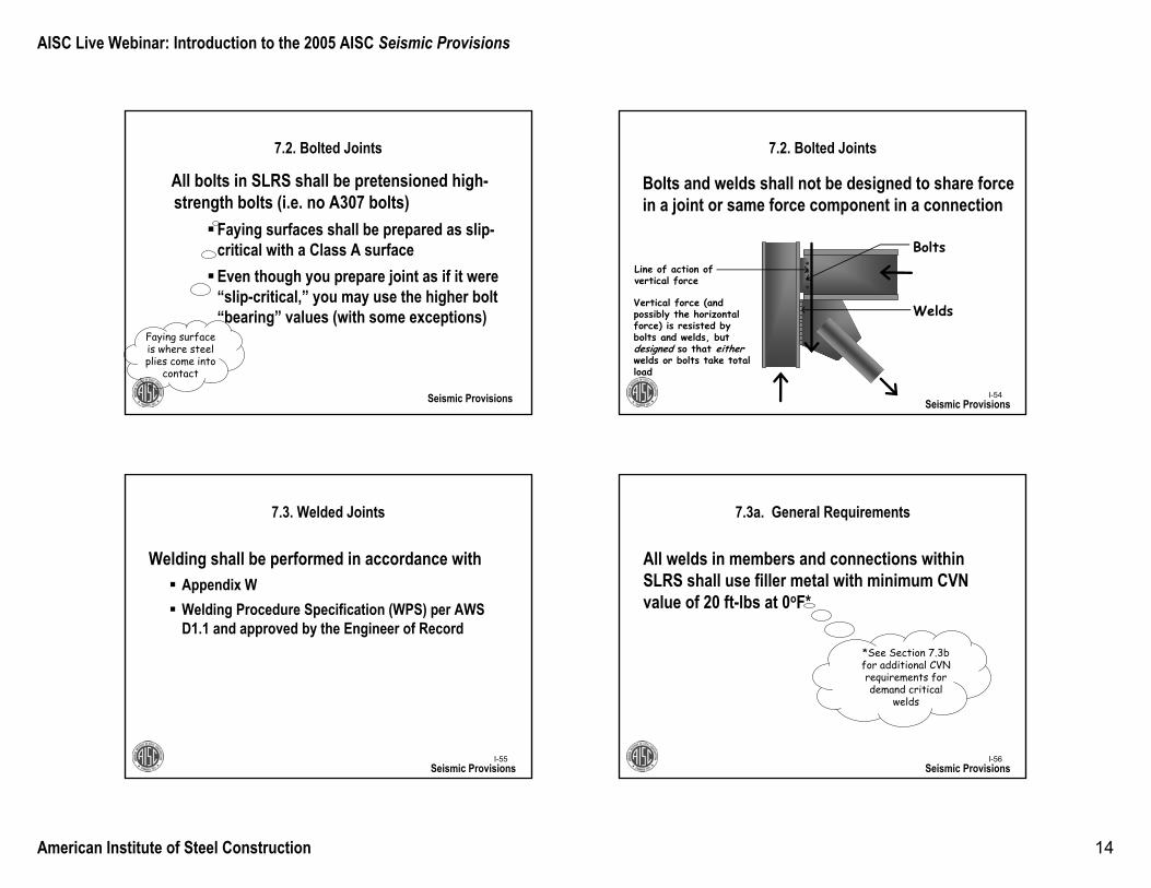
Bolts and welds shall not be designed to share forcein a joint or same force component in a connection
Seismic Provisions
Bolts
WeldsVertical force (and possibly the horizontal force) is resisted by bolts and welds, but designed so that eitherwelds or bolts take total load
Line of action of vertical force
I-55
7.3. Welded Joints
Welding shall be performed in accordance withAppendix WWelding Procedure Specification (WPS) per AWS D1.1 and approved by the Engineer of Record
Seismic ProvisionsI-56
7.3a. General Requirements
All welds in members and connections within SLRS shall use filler metal with minimum CVN value of 20 ft-lbs at 0oF*
Seismic Provisions
*See Section 7.3b for additional CVN requirements for demand critical
welds
AISC Live Webinar: Introduction to the 2005 AISC Seismic Provisions
American Institute of Steel Construction 15
I-57
7.3b. Demand Critical Welds
Where frame is normally at 50oF or higher (i.e. most conditioned structures), all welds designated as “demand critical” shall use filler metal with minimum CVN value of
20 ft-lbs at -20oF40 ft-lbs at 70oF per Appendix X
Seismic ProvisionsI-58
7.3b. Demand Critical Welds
Although demand critical welds are identified in the Seismic Provisions, there may be other welds that warrant this designation by the designer.
Seismic Provisions
I-59
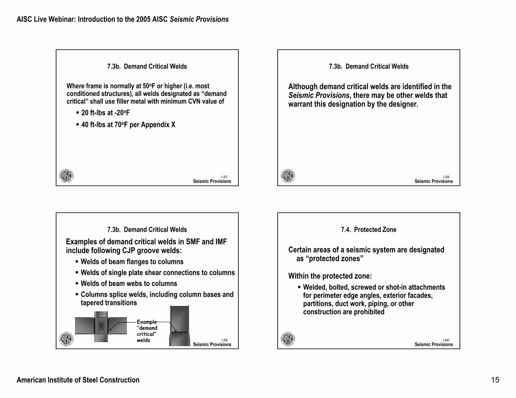
7.3b. Demand Critical WeldsExamples of demand critical welds in SMF and IMFinclude following CJP groove welds:
Welds of beam flanges to columnsWelds of single plate shear connections to columnsWelds of beam webs to columnsColumns splice welds, including column bases and tapered transitions
Seismic Provisions
Example “demand critical”welds I-60
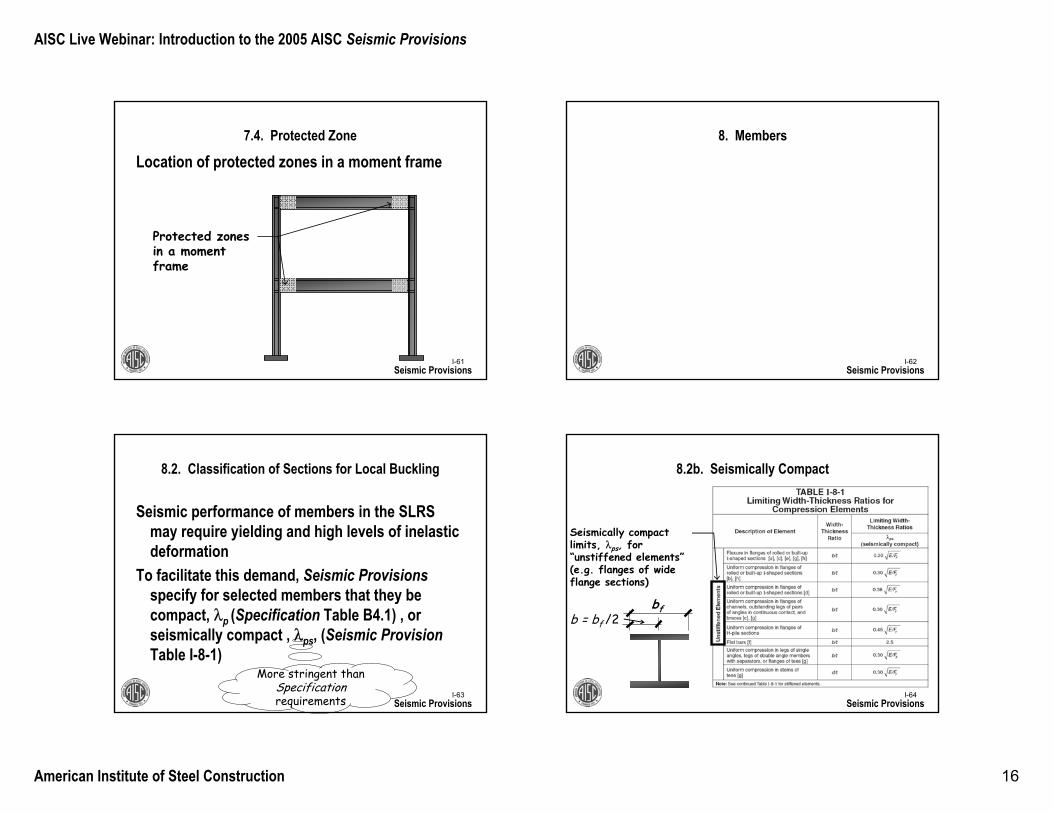
7.4. Protected Zone
Certain areas of a seismic system are designated as “protected zones”
Within the protected zone: Welded, bolted, screwed or shot-in attachments for perimeter edge angles, exterior facades, partitions, duct work, piping, or other construction are prohibited
Seismic Provisions
AISC Live Webinar: Introduction to the 2005 AISC Seismic Provisions
American Institute of Steel Construction 16
I-61
7.4. Protected Zone
Location of protected zones in a moment frame
Seismic Provisions
Protected zones in a moment frame
I-62
8. Members
Seismic Provisions
I-63
8.2. Classification of Sections for Local Buckling
Seismic performance of members in the SLRS may require yielding and high levels of inelastic deformation
To facilitate this demand, Seismic Provisionsspecify for selected members that they be compact, λp (Specification Table B4.1) , or seismically compact , λps, (Seismic Provision Table I-8-1)
Seismic Provisions
More stringent than Specificationrequirements I-64
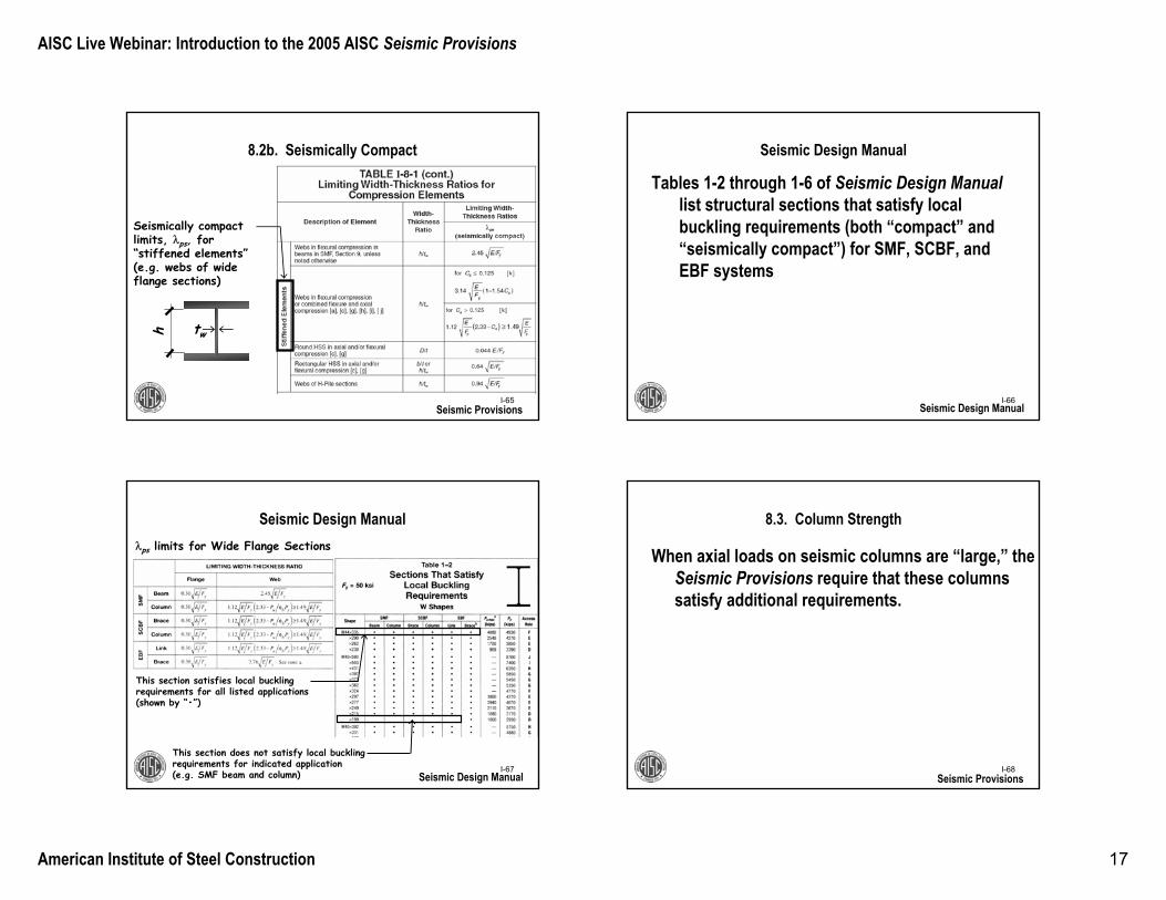
8.2b. Seismically Compact
Seismic Provisions
Seismically compact limits, λps, for “unstiffened elements”(e.g. flanges of wide flange sections)
bfb = bf /2
AISC Live Webinar: Introduction to the 2005 AISC Seismic Provisions
American Institute of Steel Construction 17
I-65
8.2b. Seismically Compact
Seismic Provisions
Seismically compact limits, λps, for “stiffened elements”(e.g. webs of wide flange sections)
twh
I-66
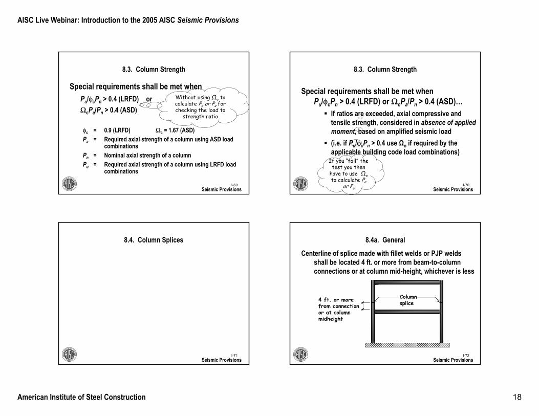
Seismic Design Manual
Tables 1-2 through 1-6 of Seismic Design Manuallist structural sections that satisfy local buckling requirements (both “compact” and “seismically compact”) for SMF, SCBF, and EBF systems
Seismic Design Manual
I-67
Seismic Design Manual
Seismic Design Manual
λps limits for Wide Flange Sections
This section satisfies local buckling requirements for all listed applications (shown by “•”)
This section does not satisfy local buckling requirements for indicated application (e.g. SMF beam and column) I-68
8.3. Column Strength
When axial loads on seismic columns are “large,” the Seismic Provisions require that these columns satisfy additional requirements.
Seismic Provisions
AISC Live Webinar: Introduction to the 2005 AISC Seismic Provisions
American Institute of Steel Construction 18
I-69
8.3. Column Strength
Special requirements shall be met when Pu/φcPn > 0.4 (LRFD) or ΩcPa/Pn > 0.4 (ASD)
Seismic Provisions
φc = 0.9 (LRFD) Ωc = 1.67 (ASD)Pa = Required axial strength of a column using ASD load
combinationsPn = Nominal axial strength of a columnPu = Required axial strength of a column using LRFD load
combinations
Without using Ωo to calculate Pa or Pu for checking the load to
strength ratio
If you “fail” the test you then
have to use Ωoto calculate Pa
or PuI-70
8.3. Column Strength
Special requirements shall be met whenPu/φcPn > 0.4 (LRFD) or ΩcPa/Pn > 0.4 (ASD)…
If ratios are exceeded, axial compressive and tensile strength, considered in absence of applied moment, based on amplified seismic load(i.e. if Pu/φcPn > 0.4 use Ωo if required by the applicable building code load combinations)
Seismic Provisions
I-71
8.4. Column Splices
Seismic ProvisionsI-72
8.4a. General
Centerline of splice made with fillet welds or PJP welds shall be located 4 ft. or more from beam-to-column connections or at column mid-height, whichever is less
Seismic Provisions
4 ft. or more from connection or at column midheight
Column splice
AISC Live Webinar: Introduction to the 2005 AISC Seismic Provisions
American Institute of Steel Construction 19
I-73
8.4b. Columns Not Part of the Seismic Load Resisting System
Column splices in columns not in SLRS:Splice required shear strength with respect to both orthogonal axes shall be Mpc/H (LRFD) or Mpc/1.5H (ASD), where Mpc is based on the appropriate direction of applied load
Seismic Provisions
Mpc
H
Mpc
Vu
II-74
9. Special Moment Frames (SMF)
Seismic Provisions
II-75
9.1. Scope
SMF are expected to withstand significant inelastic deformations (R = 8) when subjected to design an earthquake
Seismic ProvisionsII-76
9.1. Scope
Seismic Provisions
Basic Design ProcedureCalculate demands based on building codeAnalyze frameSize “fuses” (i.e. frame girders)Size other members so fuses will governConfirm that frame satisfies drift criteria
AISC Live Webinar: Introduction to the 2005 AISC Seismic Provisions
American Institute of Steel Construction 20
II-77
9.2. Beam-to-Column Connections
Seismic ProvisionsII-78
9.2a. Requirements
All beam-to-column connections in SLRS shall satisfy:
An interstory drift angle at least 0.04 radian
Seismic Provisions
II-79
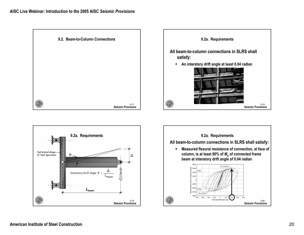
9.2a. Requirements
Seismic Provisions
Δ
Lbeam
θ
Interstory Drift Angle θ =Δ
Lbeam
Deformed shape of test specimen
II-80
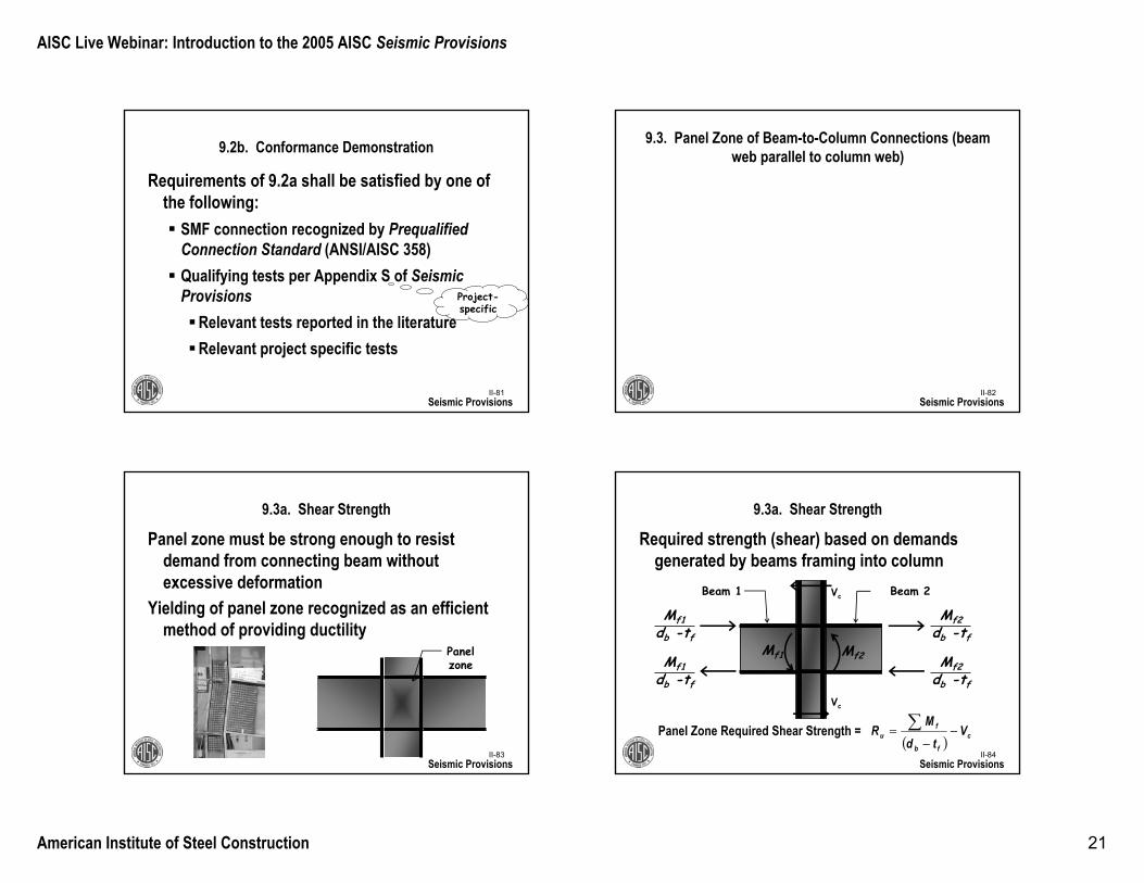
9.2a. RequirementsAll beam-to-column connections in SLRS shall satisfy:
Measured flexural resistance of connection, at face of column, is at least 80% of Mp of connected frame beam at interstory drift angle of 0.04 radian
Seismic Provisions
-40000
-30000
-20000
-10000
0
10000
20000
30000
40000
-0.08 -0.06 -0.04 -0.02 0 0.02 0.04 0.06 0.08
Interstory Drift Angle (rad)
Bea
m M
omen
t at F
ace
of C
olum
n (in
-kip
s)
0.8 Mp
- 0.8 Mp
M0.04 ≥0.8 Mp
M0.04 ≥0.8 Mp
AISC Live Webinar: Introduction to the 2005 AISC Seismic Provisions
American Institute of Steel Construction 21
II-81
9.2b. Conformance Demonstration
Requirements of 9.2a shall be satisfied by one of the following:
SMF connection recognized by PrequalifiedConnection Standard (ANSI/AISC 358)Qualifying tests per Appendix S of Seismic Provisions
Relevant tests reported in the literatureRelevant project specific tests
Seismic Provisions
Project-specific
II-82
9.3. Panel Zone of Beam-to-Column Connections (beam web parallel to column web)
Seismic Provisions
II-83
9.3a. Shear Strength
Seismic Provisions
Panel zone must be strong enough to resist demand from connecting beam without excessive deformation
Yielding of panel zone recognized as an efficient method of providing ductility
Panel zone
II-84
9.3a. Shear Strength
Seismic Provisions
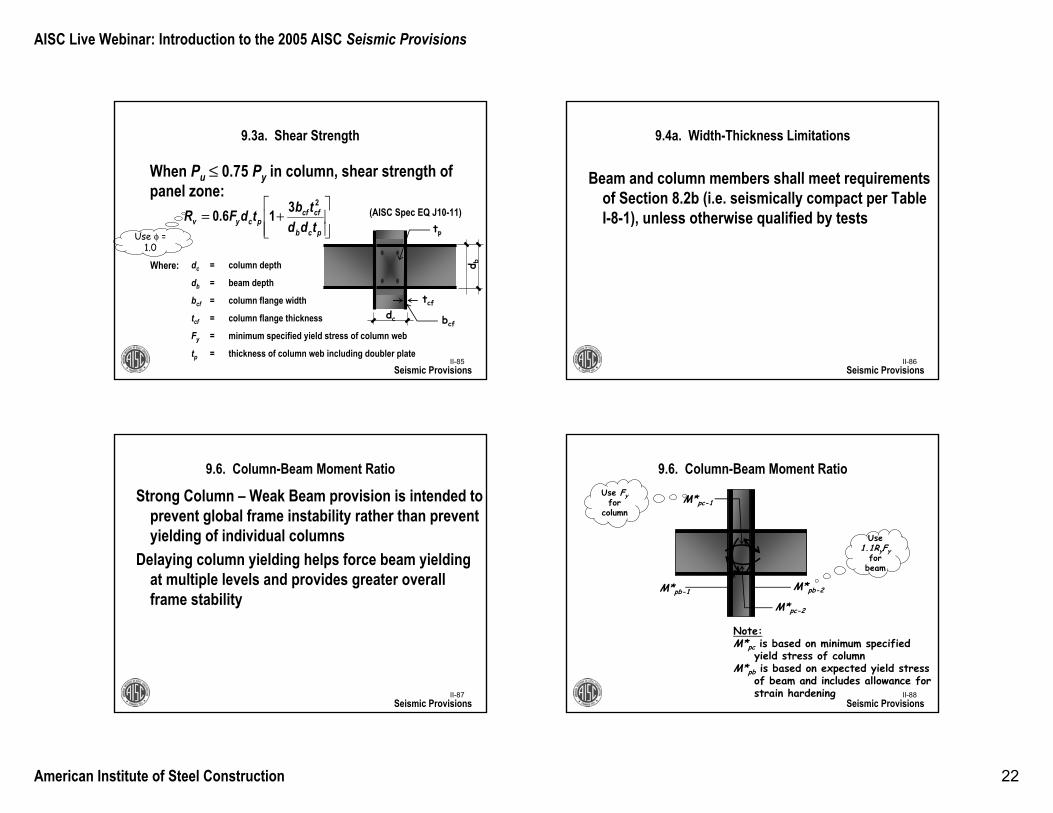
Panel Zone Required Shear Strength =
Required strength (shear) based on demands generated by beams framing into column
Beam 1 Beam 2
Mf1 Mf2
Vc
Vc
Mf2db -tf
Mf2db -tf
Mf1db -tf
Mf1db -tf
( ) cfb
fu V
tdM
R −−
= ∑
AISC Live Webinar: Introduction to the 2005 AISC Seismic Provisions
American Institute of Steel Construction 22
II-85
9.3a. Shear Strength
Seismic Provisions
When Pu ≤ 0.75 Py in column, shear strength of panel zone:
(AISC Spec EQ J10-11)
Where: dc = column depth
db = beam depth
bcf = column flange width
tcf = column flange thickness
Fy = minimum specified yield stress of column web
tp = thickness of column web including doubler plate
dc
d b
tp
tcf
bcf
⎥⎥⎦
⎤
⎢⎢⎣
⎡+=
pcb
cfcfpcyv tdd
tbtdFR2316.0
Use φ = 1.0
II-86
9.4a. Width-Thickness Limitations
Beam and column members shall meet requirements of Section 8.2b (i.e. seismically compact per Table I-8-1), unless otherwise qualified by tests
Seismic Provisions
II-87
9.6. Column-Beam Moment Ratio
Seismic Provisions
Strong Column – Weak Beam provision is intended to prevent global frame instability rather than prevent yielding of individual columns
Delaying column yielding helps force beam yielding at multiple levels and provides greater overall frame stability
II-88
9.6. Column-Beam Moment Ratio
Seismic Provisions
M*pc-1
M*pc-2
M*pb-2M*pb-1
Note:M*pc is based on minimum specified
yield stress of columnM*pb is based on expected yield stress
of beam and includes allowance for strain hardening
Use Fyfor
column
Use1.1RyFy
for beam
0.1MM
*pb
*pc >
∑∑
AISC Live Webinar: Introduction to the 2005 AISC Seismic Provisions
American Institute of Steel Construction 23
II-89
9.6. Column-Beam Moment Ratio
Exception: Eq. 9-3 need not apply if either (a) or (b) is true:
(a) Columns aren’t too heavily loaded and (i) they are located at the roof or (ii) there aren’t too manycolumns that don’t satisfy Eq. 9-3
(b) Columns are sufficiently strong compared to the columns on the floor above
Seismic ProvisionsII-90
9.7. Lateral Bracing at Beam-to-Column Connections
Seismic Provisions
II-91Seismic Provisions
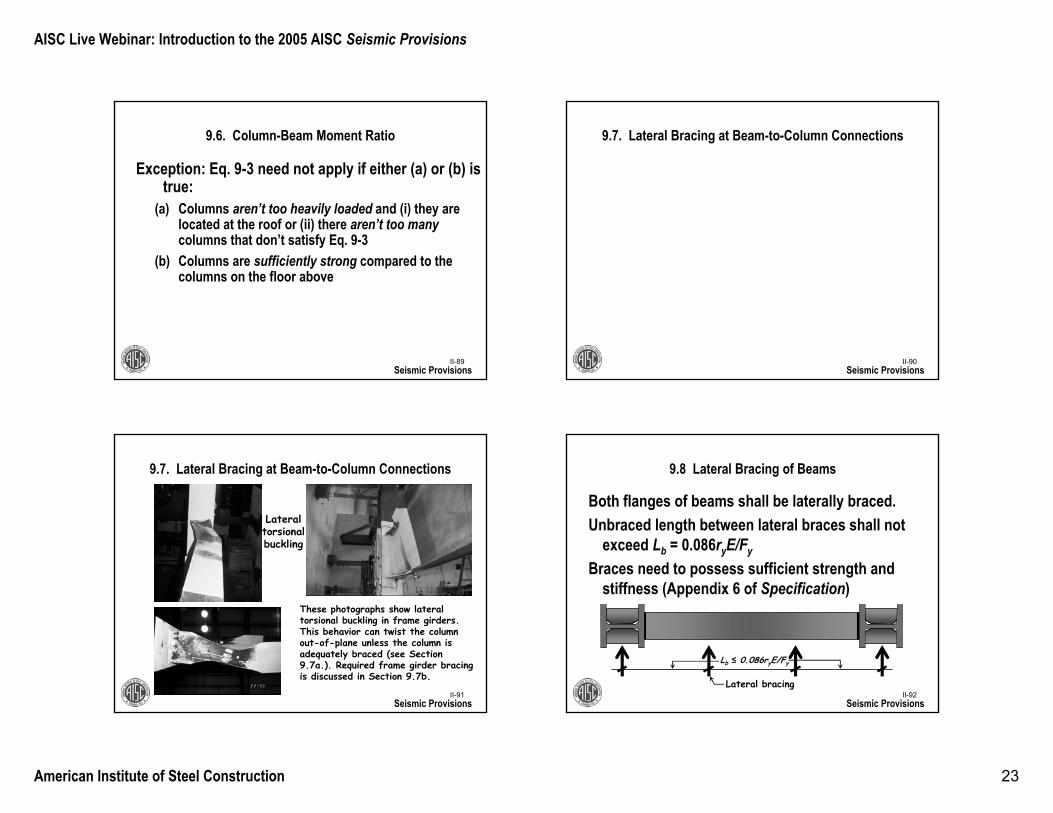
9.7. Lateral Bracing at Beam-to-Column Connections
These photographs show lateral torsional buckling in frame girders. This behavior can twist the column out-of-plane unless the column is adequately braced (see Section 9.7a.). Required frame girder bracing is discussed in Section 9.7b.
Lateral torsionalbuckling
II-92
9.8 Lateral Bracing of Beams
Both flanges of beams shall be laterally braced.Unbraced length between lateral braces shall not
exceed Lb = 0.086ryE/Fy
Braces need to possess sufficient strength and stiffness (Appendix 6 of Specification)
Seismic Provisions
Lb ≤ 0.086ryE/Fy
Lateral bracing
AISC Live Webinar: Introduction to the 2005 AISC Seismic Provisions
American Institute of Steel Construction 24
II-93
9.8 Lateral Bracing of Beams
Both flanges of beams shall be laterally braced.
Seismic Provisions
Lateral bracing provided by full-height perpendicular framing
Lateral bracing provided by shallow perpendicular framing and stiffener II-94
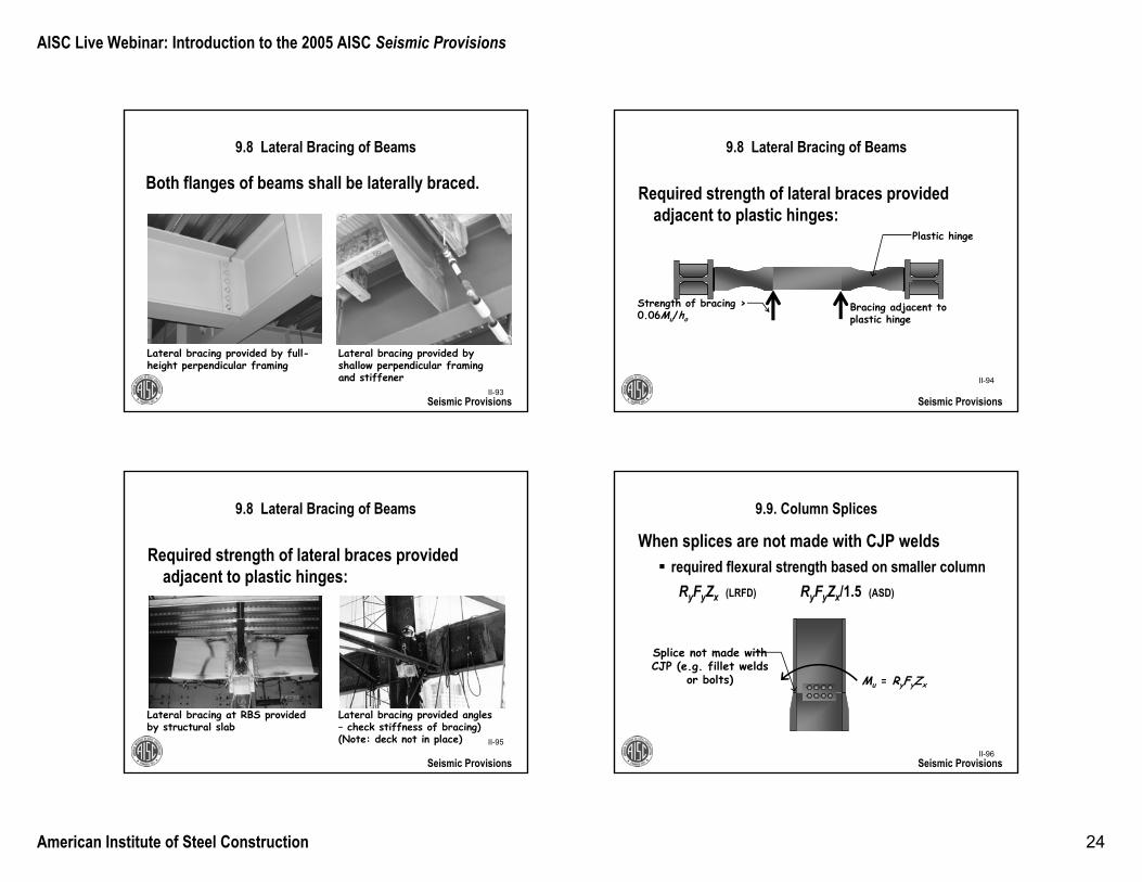
9.8 Lateral Bracing of Beams
Required strength of lateral braces provided adjacent to plastic hinges:
Seismic Provisions
Bracing adjacent to plastic hinge
Strength of bracing > 0.06Mu/ho
Plastic hinge
II-95
9.8 Lateral Bracing of Beams
Required strength of lateral braces provided adjacent to plastic hinges:
Seismic Provisions
Lateral bracing at RBS provided by structural slab
Lateral bracing provided angles – check stiffness of bracing) (Note: deck not in place)
II-96
9.9. Column Splices
When splices are not made with CJP weldsrequired flexural strength based on smaller column
RyFyZx (LRFD) RyFyZx/1.5 (ASD)
Seismic Provisions
Mu = RyFyZx
Splice not made with CJP (e.g. fillet welds
or bolts)
AISC Live Webinar: Introduction to the 2005 AISC Seismic Provisions
American Institute of Steel Construction 25
II-97
9.9. Column Splices
When splices are not made with CJP weldsrequired shear strength based onΣMpc/H (LRFD) ΣMpc/(1.5H) (ASD)
where ΣMpc is sum of nominal plastic flexural strengths of columns above and below the splice
Seismic Provisions
Mpc2
H
Mpc1
Vu
II-98
10. Intermediate Moment Frames (IMF)
Seismic Provisions
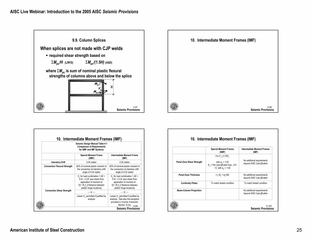
II-99Seismic Provisions
Seismic Design Manual Table 4-1Comparison of Requirements
for SMF and IMF Systems
Special Moment Frame (SMF)
Intermediate Moment Frame (IMF)
Interstory Drift 0.04 radian 0.02 radianConnection Flexural Strength 80% of nominal plastic moment of
the connection at interstory drift angle of 0.04 radian
80% of nominal plastic moment of the connection at interstory drift
angle of 0.02 radian
Connection Shear Strength
Vu for load combination 1.2D + 0.5L + 0.2S plus shear from
application of moment of 2[1.1RyFyZ/distance between
plastic hinge locations]
Vu for load combination 1.2D + 0.5L + 0.2S plus shear from
application of moment of 2[1.1RyFyZ/distance between
plastic hinge locations]― or ― ― or ―
Lesser Vu permitted if justified by analysis
Lesser Vu permitted if justified by analysis. See also the exception provided in Seismic Provisions
Section 10.2a.
10. Intermediate Moment Frames (IMF)
II-100Seismic Provisions
Special Moment Frames (SMF)
Intermediate Moment Frames (IMF)
Panel Zone Shear Strength
For Pr < 0.75Pc
with φv = 1.00Rn = Per Specification Eqn. J10-
12, with φv = 1.00
No additional requirements beyond AISC Specification
Panel Zone Thickness t > (dz + wz)/90 No additional requirements beyond AISC Specification
Continuity Plates To match tested condition To match tested condition
Beam-Column Proportion No additional requirements beyond AISC Specification
10. Intermediate Moment Frames (IMF)
AISC Live Webinar: Introduction to the 2005 AISC Seismic Provisions
American Institute of Steel Construction 26
II-101
11. Ordinary Moment Frames (OMF)
Seismic ProvisionsII-102
11.1. Scope
OMF are expected to withstand minimal inelastic deformations (R = 3.5) in their members and connections when subjected to design earthquake.
Model codes place significant limits on where OMF may be used
Seismic Provisions
II-103
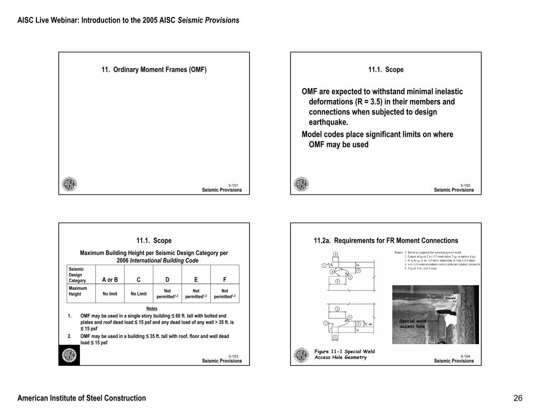
11.1. Scope
Seismic Provisions
Seismic Design Category A or B C D E FMaximum Height No limit No Limit Not
permitted1,2Not
permitted1,2Not
permitted1,2
Maximum Building Height per Seismic Design Category per 2006 International Building Code
Notes1. OMF may be used in a single story building ≤ 60 ft. tall with bolted end
plates and roof dead load ≤ 15 psf and any dead load of any wall > 35 ft. is ≤ 15 psf
2. OMF may be used in a building ≤ 35 ft. tall with roof, floor and wall dead load ≤ 15 psf
II-104
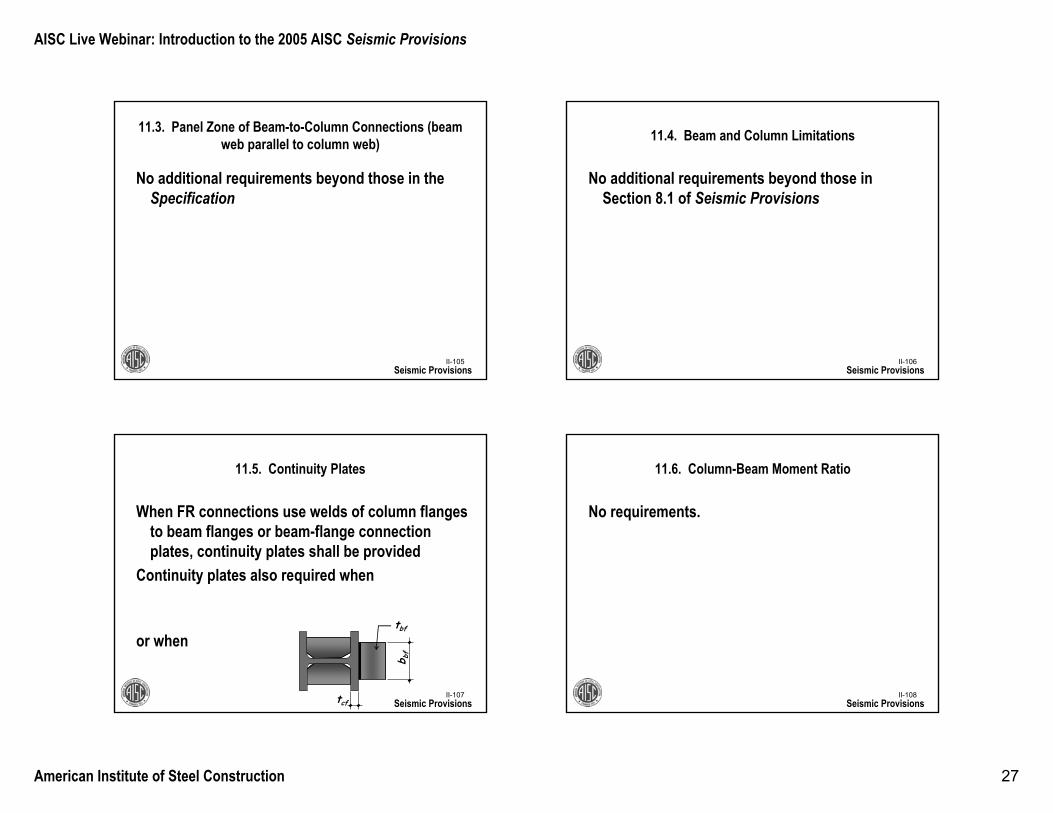
11.2a. Requirements for FR Moment Connections
Seismic Provisions
Figure 11-1 Special Weld Access Hole Geometry
Special weld access hole
AISC Live Webinar: Introduction to the 2005 AISC Seismic Provisions
American Institute of Steel Construction 27
II-105
11.3. Panel Zone of Beam-to-Column Connections (beam web parallel to column web)
No additional requirements beyond those in the Specification
Seismic ProvisionsII-106
11.4. Beam and Column Limitations
No additional requirements beyond those in Section 8.1 of Seismic Provisions
Seismic Provisions
II-107
11.5. Continuity Plates
When FR connections use welds of column flanges to beam flanges or beam-flange connection plates, continuity plates shall be provided
Continuity plates also required when
or when
Seismic Provisionstcf
b bf
tbf
ycybbffcf FFtbt /54.0<
6/bfcf bt <
II-108
11.6. Column-Beam Moment Ratio
No requirements.
Seismic Provisions
AISC Live Webinar: Introduction to the 2005 AISC Seismic Provisions
American Institute of Steel Construction 28
II-109
11.7. Lateral Bracing at Beam-to-Column Connections
No additional requirements beyond those in the Specification
Seismic ProvisionsII-110
11.8. Lateral Bracing of Beams
No additional requirements beyond those in the Specification
Seismic Provisions
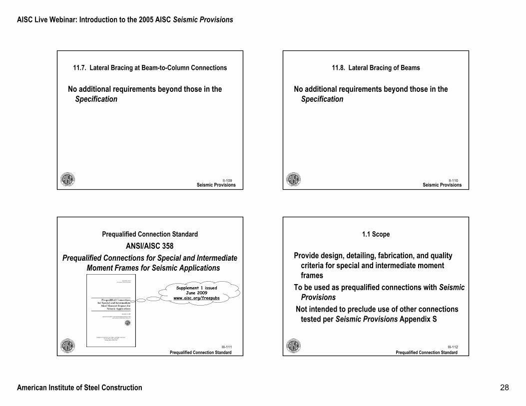
III-111
Prequalified Connection Standard
Prequalified Connection Standard
ANSI/AISC 358 Prequalified Connections for Special and Intermediate
Moment Frames for Seismic Applications
Supplement 1 issued June 2009
www.aisc.org/freepubs
III-112
1.1 Scope
Provide design, detailing, fabrication, and quality criteria for special and intermediate moment frames
To be used as prequalified connections with Seismic Provisions
Not intended to preclude use of other connections tested per Seismic Provisions Appendix S
Prequalified Connection Standard
AISC Live Webinar: Introduction to the 2005 AISC Seismic Provisions
American Institute of Steel Construction 29
III-113
5. Reduced Beam Section (RBS) Moment Connection
Prequalified Connection StandardIII-114
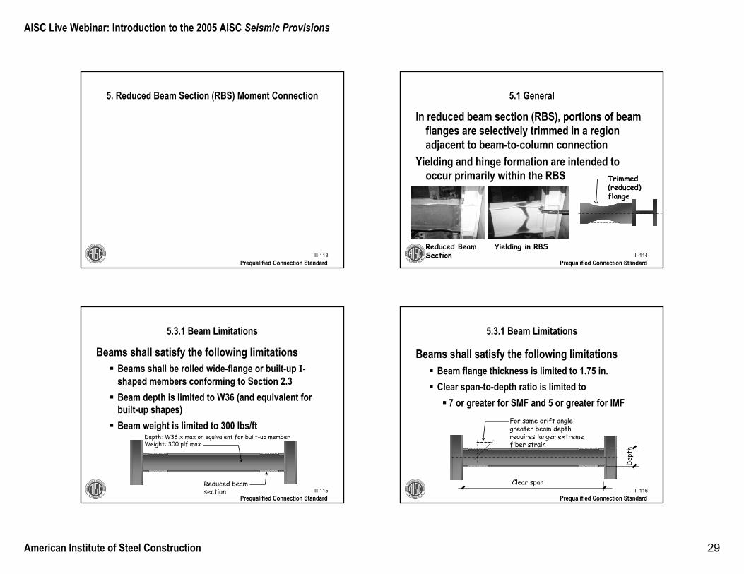
5.1 General
In reduced beam section (RBS), portions of beam flanges are selectively trimmed in a region adjacent to beam-to-column connection
Yielding and hinge formation are intended to occur primarily within the RBS Trimmed
(reduced) flange
Reduced Beam Section
Yielding in RBS
Prequalified Connection Standard
III-115
5.3.1 Beam Limitations
Beams shall satisfy the following limitationsBeams shall be rolled wide-flange or built-up I-shaped members conforming to Section 2.3Beam depth is limited to W36 (and equivalent for built-up shapes)Beam weight is limited to 300 lbs/ft
Reduced beam section
Depth: W36 x max or equivalent for built-up member Weight: 300 plf max
Prequalified Connection StandardIII-116
5.3.1 Beam Limitations
Beams shall satisfy the following limitationsBeam flange thickness is limited to 1.75 in.Clear span-to-depth ratio is limited to
7 or greater for SMF and 5 or greater for IMF
Clear span
Dep
th
For same drift angle, greater beam depth requires larger extreme fiber strain
Prequalified Connection Standard
AISC Live Webinar: Introduction to the 2005 AISC Seismic Provisions
American Institute of Steel Construction 30
III-117
5.5 Beam Flange to Column Flange Weld Limitations
Weld access hole geometry shall conform to requirements of Section J1.6 of AISC Specification(i.e. not the special weld access hole)
Prequalified Connection StandardIII-118
5.6 Beam Web to Column Connection Limitations
For SMF:Beam web shall be connected to column flange with a CJP weld extending between weld access holesSingle plate shear connection, with minimum thickness of 3/8 in., may be used as backing
Prequalified Connection Standard
III-119
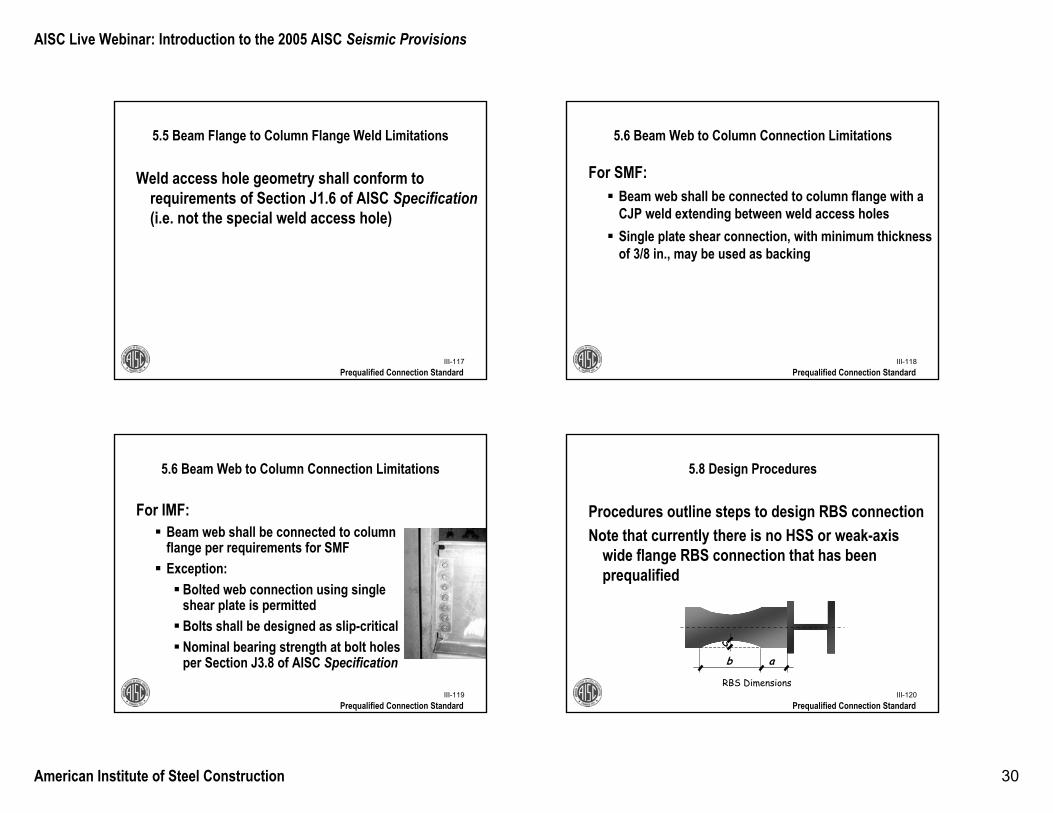
5.6 Beam Web to Column Connection Limitations
For IMF:Beam web shall be connected to column flange per requirements for SMFException:
Bolted web connection using single shear plate is permittedBolts shall be designed as slip-criticalNominal bearing strength at bolt holes per Section J3.8 of AISC Specification
Prequalified Connection StandardIII-120
5.8 Design Procedures
Procedures outline steps to design RBS connectionNote that currently there is no HSS or weak-axis
wide flange RBS connection that has been prequalified
Prequalified Connection Standard
c
b a
RBS Dimensions
AISC Live Webinar: Introduction to the 2005 AISC Seismic Provisions
American Institute of Steel Construction 31
IV-121
13. Special Concentrically Braced Frames (SCBF)
Seismic ProvisionsIV-122
13. Special Concentrically Braced Frames (SCBF)
Seismic Provisions
IV-123
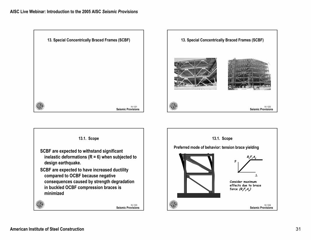
13.1. Scope
SCBF are expected to withstand significant inelastic deformations (R = 6) when subjected to design earthquake.
SCBF are expected to have increased ductility compared to OCBF because negative consequences caused by strength degradation in buckled OCBF compression braces is minimized
Seismic Provisions
Preferred mode of behavior: tension brace yielding
IV-124
13.1. Scope
Seismic Provisions
Δ
F
Consider maximum effects due to brace force (RyFyAg)
RyFyAg
AISC Live Webinar: Introduction to the 2005 AISC Seismic Provisions
American Institute of Steel Construction 32
Preferred mode of behavior: compression brace buckling
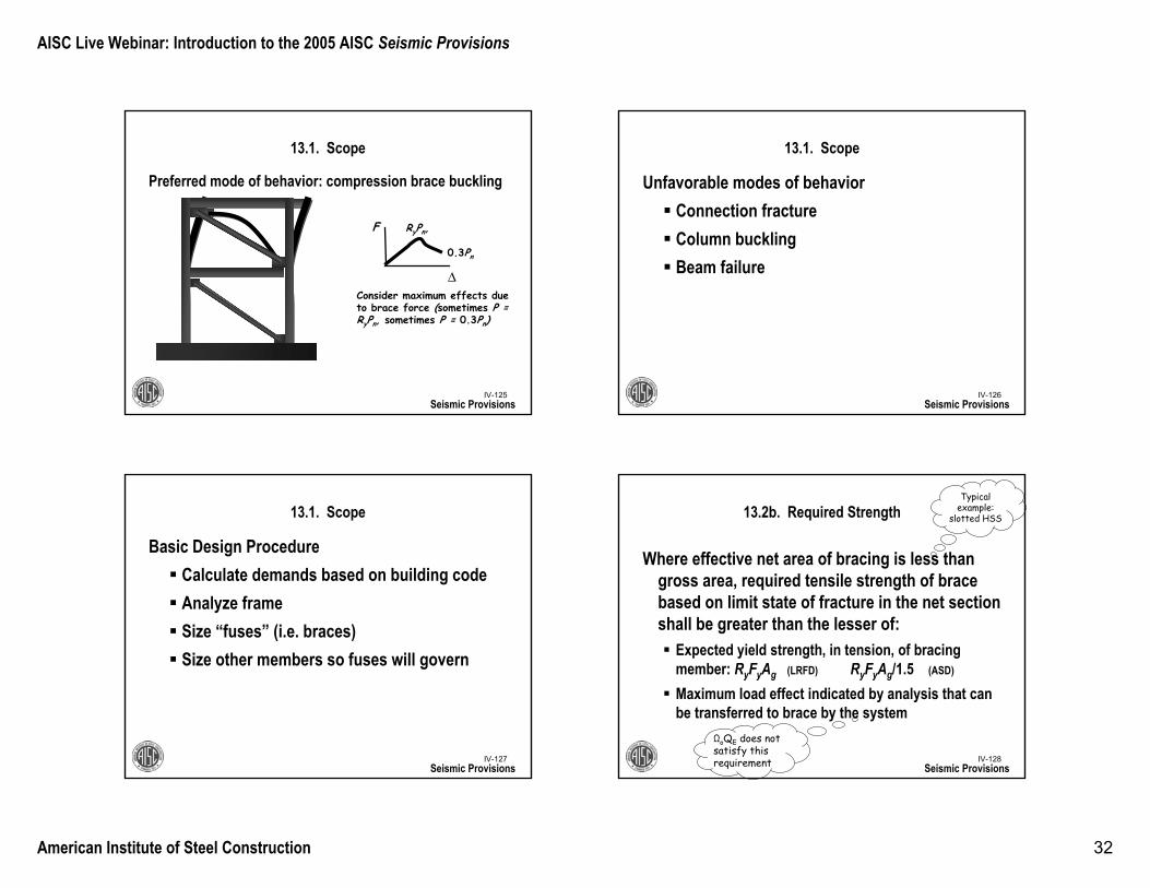
IV-125
13.1. Scope
Seismic Provisions
Δ
F
Consider maximum effects due to brace force (sometimes P = RyPn, sometimes P = 0.3Pn)
RyPn,
0.3Pn
IV-126
13.1. Scope
Seismic Provisions
Unfavorable modes of behaviorConnection fractureColumn bucklingBeam failure
IV-127
13.1. Scope
Seismic Provisions
Basic Design ProcedureCalculate demands based on building codeAnalyze frameSize “fuses” (i.e. braces)Size other members so fuses will govern
IV-128
13.2b. Required Strength
Where effective net area of bracing is less than gross area, required tensile strength of brace based on limit state of fracture in the net sectionshall be greater than the lesser of:
Expected yield strength, in tension, of bracing member: RyFyAg (LRFD) RyFyAg/1.5 (ASD)
Maximum load effect indicated by analysis that can be transferred to brace by the system
Typical example:
slotted HSS
Seismic Provisions
ΩoQE does not satisfy this requirement
AISC Live Webinar: Introduction to the 2005 AISC Seismic Provisions
American Institute of Steel Construction 33
IV-129
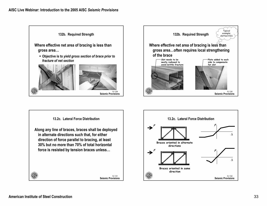
132b. Required Strength
Where effective net area of bracing is less than gross area…
Objective is to yield gross section of brace prior to fracture of net section
Seismic ProvisionsIV-130
132b. Required Strength
Where effective net area of bracing is less than gross area…often requires local strengthening of the brace
Typical example:
slotted HSS
Seismic Provisions
Slot needs to be neatly radiused to avoid brittle fracture
Plate added to each side to compensate for slot
IV-131
13.2c. Lateral Force Distribution
Along any line of braces, braces shall be deployed in alternate directions such that, for either direction of force parallel to bracing, at least 30% but no more than 70% of total horizontal force is resisted by tension braces unless…
Seismic ProvisionsIV-132
13.2c. Lateral Force Distribution
Seismic Provisions
Δ
F
Δ
F
F
F
Braces oriented in same direction
Braces oriented in alternate directions
AISC Live Webinar: Introduction to the 2005 AISC Seismic Provisions
American Institute of Steel Construction 34
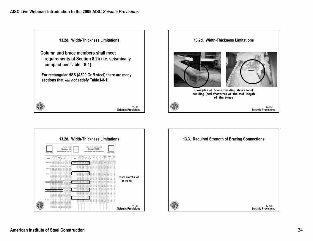
IV-133
13.2d. Width-Thickness Limitations
Column and brace members shall meet requirements of Section 8.2b (i.e. seismically compact per Table I-8-1)
Seismic Provisions
For rectangular HSS (A500 Gr B steel) there are many sections that will not satisfy Table I-8-1:
290000 64 0 64 16 146y
b E ksi. . .t F ksi
≤ = =
IV-134Seismic Provisions
Examples of brace buckling shows local buckling (and fracture) at the mid-length
of the brace
13.2d. Width-Thickness Limitations
IV-135
13.2d. Width-Thickness Limitations
Seismic Provisions
(There aren’t a lot of them)
16 1b .t
≤
IV-136
13.3. Required Strength of Bracing Connections
Seismic Provisions
AISC Live Webinar: Introduction to the 2005 AISC Seismic Provisions
American Institute of Steel Construction 35
IV-137
13.3a. Required Tensile Strength
Required tensile strength of bracing connections(including beam-to column connections if part of bracing system) shall be lesser of:
Expected yield strength of bracing member, RyFyAg (LRFD) RyFyAg/1.5 (ASD)
Maximum load effect, indicated by analysis, that can be transferred to brace by the system
Seismic Provisions
ΩoQE does not satisfy this requirement
IV-138
13.3b. Required Flexural Strength
In direction brace will buckle, required flexural strength of connection shall be equal to 1.1RyMp (LRFD) or 1.1RyMp/1.5 (ASD) of brace about critical axis.
Exception: Brace connections are permitted that:Satisfy Section 13.3a, Can accommodate inelastic rotations associated with post-buckling deformations
Seismic Provisions
Brace tensile capacity
IV-139
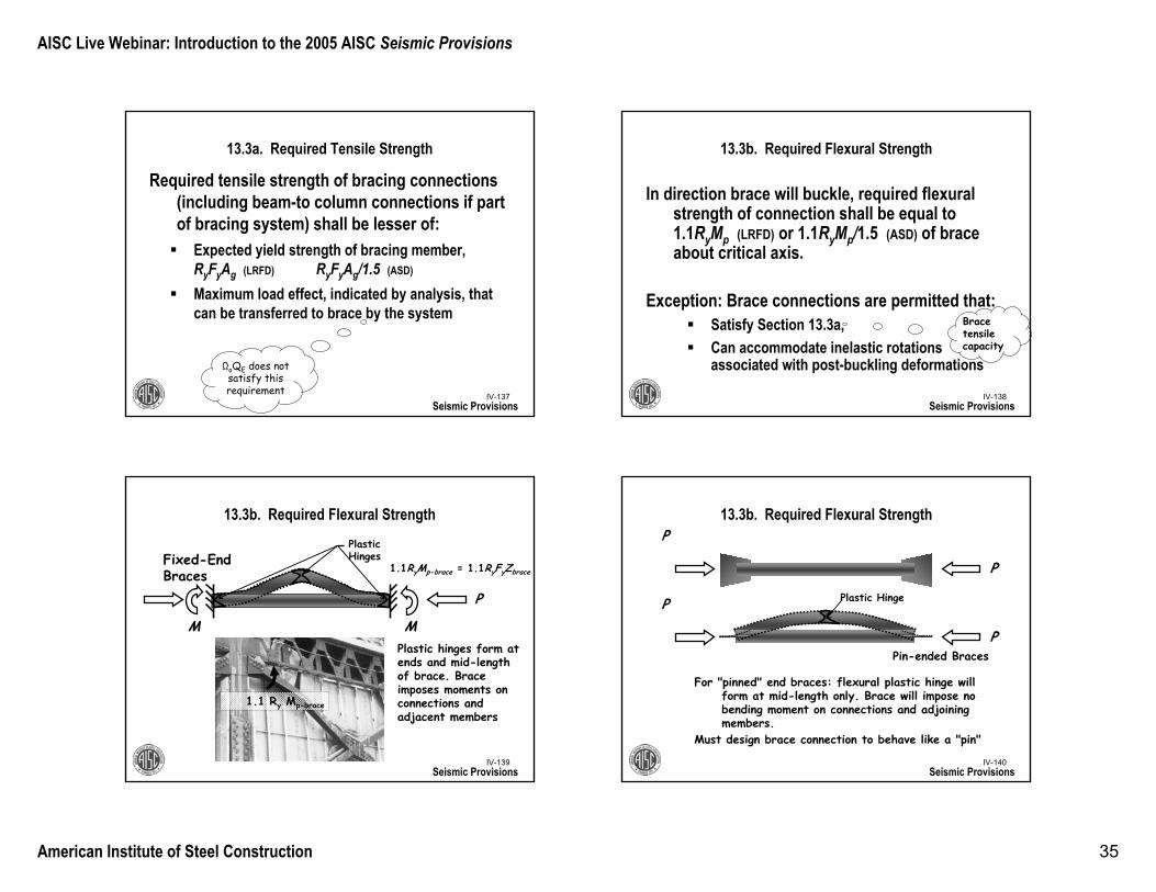
13.3b. Required Flexural Strength
Seismic Provisions
P
MM
Plastic Hinges
1.1 Ry Mp-brace
Plastic hinges form at ends and mid-length of brace. Brace imposes moments on connections and adjacent members
Fixed-End Braces 1.1RyMp-brace = 1.1RyFyZbrace
IV-140
13.3b. Required Flexural Strength
Seismic Provisions
Pin-ended Braces
P
P
P
P Plastic Hinge
For "pinned" end braces: flexural plastic hinge will form at mid-length only. Brace will impose no bending moment on connections and adjoining members.
Must design brace connection to behave like a "pin"
AISC Live Webinar: Introduction to the 2005 AISC Seismic Provisions
American Institute of Steel Construction 36
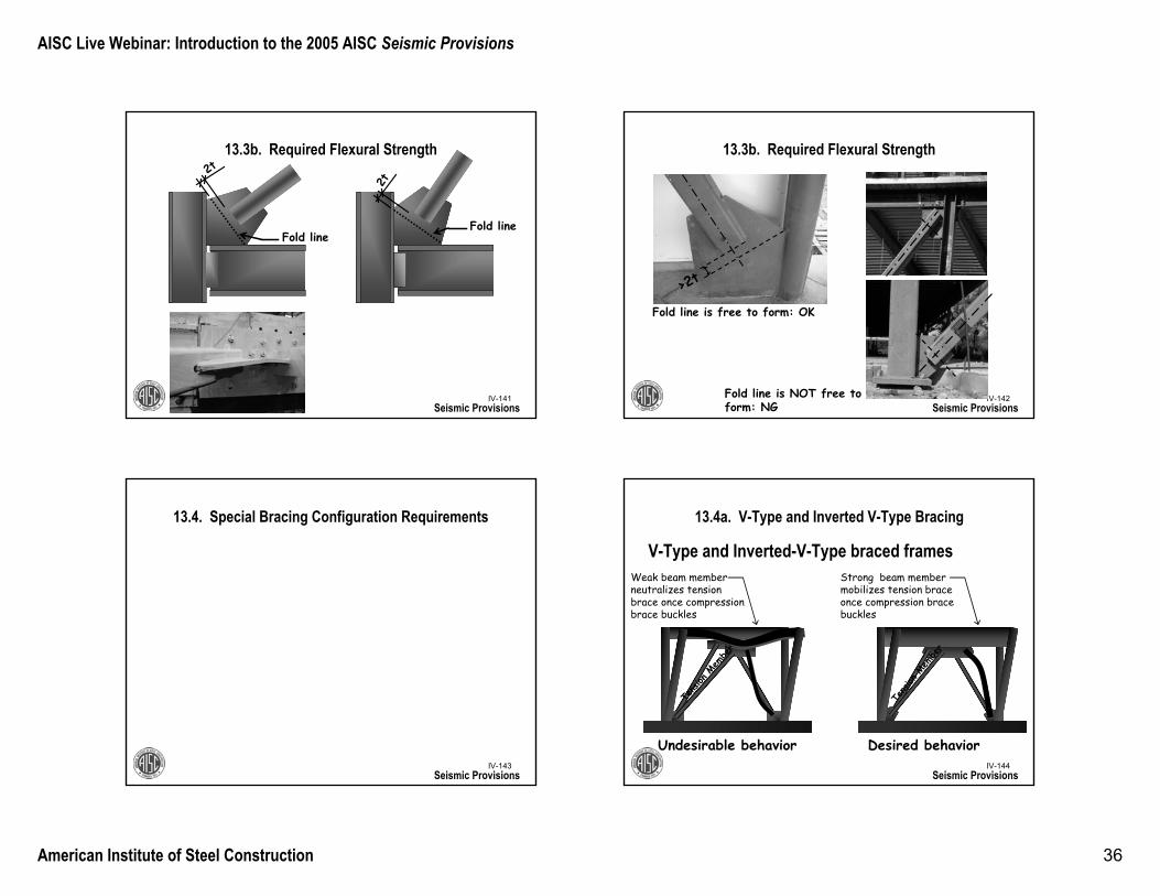
IV-141
13.3b. Required Flexural Strength
Seismic Provisions
Fold line
2t
Fold line
2tIV-142
13.3b. Required Flexural Strength
Seismic Provisions
Fold line is free to form: OK
Fold line is NOT free to form: NG
>2t
IV-143
13.4. Special Bracing Configuration Requirements
Seismic ProvisionsIV-144
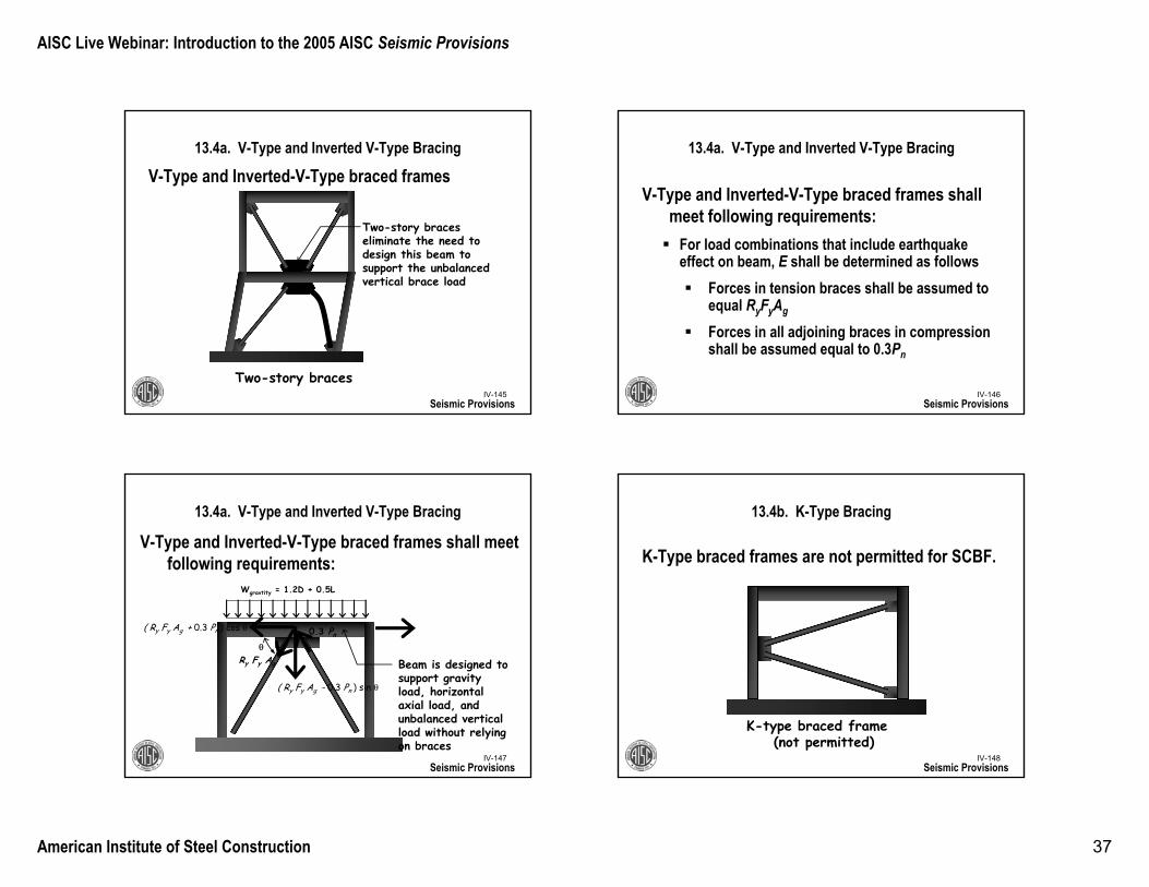
13.4a. V-Type and Inverted V-Type Bracing
V-Type and Inverted-V-Type braced frames
Seismic Provisions
Undesirable behavior Desired behavior
Weak beam member neutralizes tension brace once compression brace buckles
Tension
Mem
ber
Strong beam member mobilizes tension brace once compression brace buckles
Tension
Mem
ber
AISC Live Webinar: Introduction to the 2005 AISC Seismic Provisions
American Institute of Steel Construction 37
IV-145
13.4a. V-Type and Inverted V-Type Bracing
V-Type and Inverted-V-Type braced frames
Seismic Provisions
Two-story braces
Two-story braces eliminate the need to design this beam to support the unbalanced vertical brace load
IV-146
13.4a. V-Type and Inverted V-Type Bracing
V-Type and Inverted-V-Type braced frames shall meet following requirements:
For load combinations that include earthquake effect on beam, E shall be determined as follows
Forces in tension braces shall be assumed to equal RyFyAg
Forces in all adjoining braces in compressionshall be assumed equal to 0.3Pn
Seismic Provisions
V-Type and Inverted-V-Type braced frames shall meet following requirements:
IV-147
Wgravtity = 1.2D + 0.5L
Ry Fy Ag
0.3 Pn
θ
13.4a. V-Type and Inverted V-Type Bracing
Seismic Provisions
( Ry Fy Ag - 0.3 Pn ) sin θ
( Ry Fy Ag + 0.3 Pn ) cos θ
Beam is designed to support gravity load, horizontal axial load, and unbalanced vertical load without relying on braces
IV-148
13.4b. K-Type Bracing
K-Type braced frames are not permitted for SCBF.
Seismic Provisions
K-type braced frame (not permitted)
AISC Live Webinar: Introduction to the 2005 AISC Seismic Provisions
American Institute of Steel Construction 38
IV-149
13.5. Column Splices
In addition to meeting requirements of Section 8.4, column splices in SCBF shall:
50% of available flexural strength of smaller connected section. Required shear strength shall be ΣMpc/H (LRFD)or ΣMpc/(1.5H) (ASD)
where ΣMpc is sum of nominal plastic flexural strengths of columns above and below the splice
Seismic ProvisionsIV-150
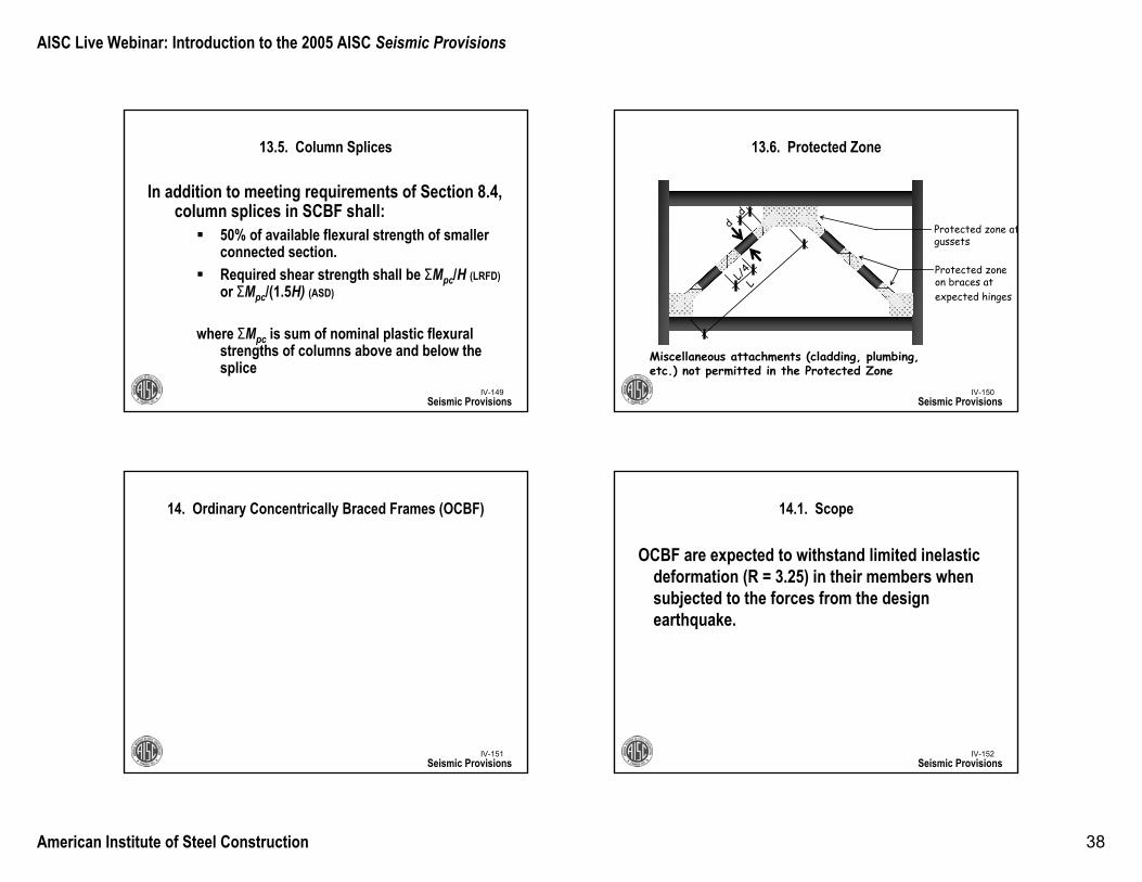
13.6. Protected Zone
Seismic Provisionsd
d
LL/
4
Protected zone atgussets
Protected zone on braces atexpected hinges
Miscellaneous attachments (cladding, plumbing, etc.) not permitted in the Protected Zone
IV-151
14. Ordinary Concentrically Braced Frames (OCBF)
Seismic ProvisionsIV-152
14.1. Scope
OCBF are expected to withstand limited inelastic deformation (R = 3.25) in their members when subjected to the forces from the design earthquake.
Seismic Provisions
AISC Live Webinar: Introduction to the 2005 AISC Seismic Provisions
American Institute of Steel Construction 39
IV-153
14.2. Bracing Members
Seismic Provisions
Basically the same as SCBF
Bracing shall meet the requirements of Section 8.2b (i.e. seismically compact)Exception: braces filled with concrete need not comply with this
provision
Braces with Kl/r greater than 4√(Es/Fy) shall not be used in V-type or inverted-V-type configurations.
IV-154Seismic Provisions
Basically the same as SCBF
V-Type, Inverted-V-Type and K-type braced frames shall meet following requirements:
Beam that is intersected by braces shall be continuousbetween columns (V-Type, Inverted-V-Type)Column that is intersected by braces shall be continuous between beams (K-Type)
Unique to OCBF
14.3. Special Bracing Configuration Requirements
IV-155
14.3. Special Bracing Configuration Requirements
V-Type, Inverted-V-Type and K-type braced frames shall meet following requirements:
Required strength of beam intersected by braces, their connections and supporting members shall be determined based on load combinations of building code assuming braces support no dead and live loads.
Seismic Provisions
Basically the same as SCBF
IV-156
14.3. Special Bracing Configuration Requirements
Seismic Provisions
Basically the same as SCBF
V-Type, Inverted-V-Type and K-type braced frames shall meet following requirements:
For load combinations that include earthquake effect on beam, E shall be determined as follows
Forces in tension braces shall be assumed to equal RyFyAg
For V-type and Inverted V-type, brace tension forces need not exceed maximum force developed by systemForces in compression braces shall be assumed equal to 0.3Pn
AISC Live Webinar: Introduction to the 2005 AISC Seismic Provisions
American Institute of Steel Construction 40
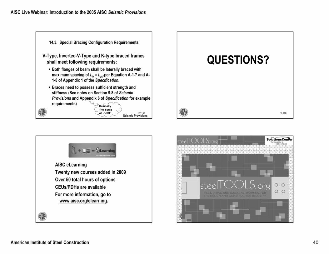
IV-157
14.3. Special Bracing Configuration Requirements
Seismic Provisions
Basically the same as SCBF
V-Type, Inverted-V-Type and K-type braced frames shall meet following requirements:
Both flanges of beam shall be laterally braced with maximum spacing of Lb = Lpd per Equation A-1-7 and A-1-8 of Appendix 1 of the Specification. Braces need to possess sufficient strength and stiffness (See notes on Section 9.8 of Seismic Provisions and Appendix 6 of Specification for example requirements)
IV-158
QUESTIONS?
AISC eLearningTwenty new courses added in 2009Over 50 total hours of optionsCEUs/PDHs are availableFor more information, go to
www.aisc.org/elearning.
AISC Live Webinar: Introduction to the 2005 AISC Seismic Provisions
American Institute of Steel Construction 41
Learn why so many engineers insist on it!
Over 1000 certified companies world wide.
Proof in the form of a rigorous independent audit.
Save your clients substantial money on code required special inspection.
To find an AISC Certified company in your area, visit www.aisc.org/certification
Please give us your feedback!www.aisc.org/cesurvey
American Institute of Steel ConstructionOne East Wacker Drive, Suite 700
Chicago, IL 60601
Thank You
American Institute of Steel ConstructionOne East Wacker Drive, Suite 700
Chicago, IL 60601